

Page 1

vacon nx
ac drives
“all in one”
application manual
Page 2

vacon • 1
INDEX
Document ID:DPD00903A
Revision release date: 30.3.2012
1. Basic Application.............................................................................................5
1.1. Introduction ......................................................................................................................5
1.1.1. Motor protection functions in the Basic Application .......................................................5
1.2. Control I/O ........................................................................................................................6
1.3. Control signal logic in Basic Application .........................................................................7
1.4. Basic Application – Parameter lists ................................................................................8
1.4.1. Monitoring values (Control keypad: menu M1) ...............................................................8
1.4.2. Basic parameters (Control keypad: Menu M2 -> G2.1) ...................................................9
1.4.3. Keypad control (Control keypad: Menu M3) ..................................................................10
1.4.4. System menu (Control keypad: Menu M6).....................................................................10
1.4.5. Expander boards (Control keypad: Menu M7) ...............................................................10
2. Standard Application .................................................................................... 11
2.1. Introduction ....................................................................................................................11
2.2. Control I/O ......................................................................................................................12
2.3. Control signal logic in Standard Application .................................................................13
2.4. Standard Application – Parameter lists ........................................................................14
2.4.1. Monitoring values (Control keypad: menu M1) .............................................................14
2.4.2. Basic parameters (Control keypad: Menu M2 -> G2.1) .................................................15
2.4.3. Input signals (Control keypad: Menu M2 -> G2.2) .........................................................16
2.4.4. Output signals (Control keypad: Menu M2 -> G2.3).......................................................17
2.4.5. Drive control parameters (Control keypad: Menu M2 -> G2.4).....................................18
2.4.6. Prohibit frequency parameters (Control keypad: Menu M2 -> G2.5)............................19
2.4.7. Motor control parameters (Control keypad: Menu M2 -> G2.6)....................................19
2.4.8. Protections (Control keypad: Menu M2 -> G2.7) ...........................................................20
2.4.9. Autorestart parameters (Control keypad: Menu M2 -> G2.8) .......................................22
2.4.10. Keypad control (Control keypad: Menu M3) ................................................................22
2.4.11. System menu (Control keypad: M6).............................................................................23
2.4.12. Expander boards (Control keypad: Menu M7) .............................................................23
3. Local/Remote Control Application................................................................ 24
3.1. Introduction ....................................................................................................................24
3.2. Control I/O ......................................................................................................................25
3.3. Control signal logic in Local/Remote Application .........................................................26
3.4. Local/Remote control application – Parameter lists ....................................................27
3.4.1. Monitoring values (Control keypad: menu M1) .............................................................27
3.4.2. Basic parameters (Control keypad: Menu M2 -> G2.1) .................................................28
3.4.3. Input signals (Control keypad: Menu M2 -> G2.2) .........................................................29
3.4.4. Output signals (Control keypad: Menu M2 -> G2.3).......................................................31
3.4.5. Drive control parameters (Control keypad: Menu M2 -> G2.4).....................................33
3.4.6. Prohibit frequency parameters (Control keypad: Menu M2 -> G2.5)............................33
3.4.7. Motor control parameters (Control keypad: Menu M2 -> G2.6)....................................34
3.4.8. Protections (Control keypad: Menu M2 -> G2.7) ...........................................................35
3.4.9. Autorestart parameters (Control keypad: Menu M2 -> G2.8) .......................................37
3.4.10. Keypad control (Control keypad: Menu M3) ................................................................37
3.4.11. System menu (Control keypad: Menu M6)...................................................................38
3.4.12. Expander boards (Control keypad: Menu M7) .............................................................38
4. Multi-step Speed Control Application ...........................................................39
4.1. Introduction ....................................................................................................................39
4.2. Control I/O ......................................................................................................................40
4.3. Control signal logic in Multi-Step Speed Control Application.......................................41
4.4. Multi-step speed control application – Parameter lists ...............................................42
4.4.1. Monitoring values (Control keypad: menu M1) .............................................................42
Tel. +358 (0) 201 2121 • Fax +358 (0)201 212 205
Page 3

vacon • 2
4.4.2. Basic parameters (Control keypad: Menu M2 -> G2.1) .................................................43
4.4.3. Input signals (Control keypad: Menu M2 -> G2.2) .........................................................44
4.4.4. Output signals (Control keypad: Menu M2 -> G2.3).......................................................46
4.4.5. Drive control parameters (Control keypad: Menu M2 -> G2.4).....................................48
4.4.6. Prohibit frequency parameters (Control keypad: Menu M2 -> G2.5)............................49
4.4.7. Motor control parameters (Control keypad: Menu M2 à G2.6) .....................................49
4.4.8. Protections (Control keypad: Menu M2 -> G2.7) ...........................................................51
4.4.9. Autorestart parameters (Control keypad: Menu M2 -> G2.8) .......................................52
4.4.10. Keypad control (Control keypad: Menu M3) ................................................................52
4.4.11. System menu (Control keypad: M6).............................................................................52
4.4.12. Expander boards (Control keypad: Menu M7) .............................................................52
5. PID Control Application.................................................................................53
5.1. Introduction ....................................................................................................................53
5.2. Control I/O ......................................................................................................................54
5.3. Control signal logic in PID Control Application .............................................................55
5.4. PID Application – Parameter lists..................................................................................56
5.4.1. Monitoring values (Control keypad: menu M1) .............................................................56
5.4.2. Basic parameters (Control keypad: Menu M2 -> G2.1) .................................................57
5.4.3. Input signals (Control keypad: Menu M2 -> G2.2) .........................................................58
5.4.4. Output signals (Control keypad: Menu M2 -> G2.3)......................................................61
5.4.5. Drive control parameters (Control keypad: Menu M2 -> G2.4).....................................63
5.4.6. Prohibit frequency parameters (Control keypad: Menu M2 -> G2.5)............................63
5.4.7. Motor control parameters (Control keypad: Menu M2 -> G2.6)....................................64
5.4.8. Protections (Control keypad: Menu M2 -> G2.7) ...........................................................66
5.4.9. Autorestart parameters (Control keypad: Menu M2 -> G2.8) .......................................67
5.4.10. Keypad control (Control keypad: Menu M3) ................................................................68
5.4.11. System menu (Control keypad: M6).............................................................................68
5.4.12. Expander boards (Control keypad: Menu M7) .............................................................68
6. Multi-purpose Control Application ............................................................... 69
6.1. Introduction ....................................................................................................................69
6.2. Control I/O ......................................................................................................................70
6.3. Control signal logic in Multi-Purpose Control Application ...........................................71
6.4. “Terminal To Function” (TTF) programming principle..................................................72
6.4.1. Defining an input/output for a certain function on keypad ...........................................72
6.4.2. Defining a terminal for a certain function with NCDrive programming tool ................73
6.4.3. Defining unused inputs/outputs ....................................................................................73
6.5. Master/Follower function (NXP only).............................................................................74
6.5.1. Master/Follower link physical connections...................................................................74
6.5.2. Optical fibre connection between frequency converters with OPTD2...........................74
6.6. Multi-purpose Control Application – Parameter lists...................................................75
6.6.1. Monitoring values (Control keypad: menu M1) .............................................................75
6.6.1.1. Digital input statuses: ID15 and ID16 ............................................................................77
6.6.1.2. Digital input statuses: ID56 and ID57 ............................................................................78
6.6.1.3. Fault Word 1, ID1172..................................................................................................... 78
6.6.1.4. Fault Word 2, ID1173......................................................................................................79
6.6.1.5. Warning Word 1, ID1174 ................................................................................................79
6.6.1.6. SystemBus Status Word, ID1601 ...................................................................................79
6.6.1.7. Follower drive Status Word ...........................................................................................80
6.6.1.8. Application Status Word ................................................................................................80
6.6.2. Basic parameters (Control keypad: Menu M2 -> G2.1) .................................................82
6.6.3. Input signals...................................................................................................................83
6.6.3.1. Basic Settings (Control keypad: Menu M2 -> G2.2.1)....................................................83
6.6.3.2. Analogue input 1 (Control keypad: Menu M2 -> G2.2.2)................................................84
6.6.3.3. Analogue input 2 (Control keypad: Menu M2 -> G2.2.3)................................................84
6.6.3.4. Analogue input 3 (Control keypad: Menu M2 -> G2.2.4)...............................................85
24-hour support +358 (0)201 212 575 • Email: vacon@vacon.com
Page 4

vacon • 3
6.6.3.5. Analogue input 4 (Control keypad: Menu M2 -> G2.2.5)...............................................85
6.6.3.6. Free analogue input, signal selection (Keypad: Menu M2 -> G2.2.6) ...........................86
6.6.3.7. Digital inputs (Control keypad: Menu M2 -> G2.2.4).....................................................86
6.6.4. Output signals ................................................................................................................88
6.6.4.1. Delayed digital output 1 (Keypad: Menu M2 -> G2.3.1) .................................................88
6.6.4.2. Delayed digital output 2 (Keypad: Menu M2 -> G2.3.2) .................................................88
6.6.4.3. Digital output signals (Control keypad: Menu M2 -> G2.3.3) ........................................89
6.6.4.4. Limit settings (Control keypad: Menu M2 -> G2.3.4)....................................................90
6.6.4.5. Analogue output 1 (Control keypad: Menu M2 -> G2.3.5) .............................................91
6.6.4.6. Analogue output 2 (Control keypad: Menu M2 -> G2.3.6) .............................................91
6.6.4.7. Analogue output 3 (Control keypad: Menu M2 -> G2.3.7) .............................................92
6.6.5. Drive control parameters (Control keypad: Menu M2 -> G2.4)....................................93
6.6.6. Prohibit frequency parameters (Control keypad: Menu M2 -> G2.5)...........................94
6.6.7. Motor control parameters (Control keypad: Menu M2 -> G2.6)...................................94
6.6.7.1. Closed Loop parameters (Control keypad: Menu M2 ->G2.6.23)..................................95
6.6.7.2. NXP drives: PMS Motor control parameters (Control keypad: Menu M2 -> G2.6.24) ..96
6.6.7.3. NXP drives: Identification parameters (Control keypad: Menu M2 -> G2.6.25)............96
6.6.8. Protections (Control keypad: Menu M2 -> G2.7) ...........................................................97
6.6.9. Autorestart parameters (Control keypad: Menu M2 -> G2.8) .......................................99
6.6.10. Fieldbus parameters (Control Keypad: Menu M2 ->G2.9).........................................100
6.6.11. Torque control parameters (Control Keypad: Menu M2 -> G2.10)............................101
6.6.12. NXP drives: Master Follower parameters (Control keypad: Menu M2 -> G2.11) .....102
6.6.13. Keypad control (Control keypad: Menu M3) ..............................................................103
6.6.14. System menu (Control keypad: Menu M6).................................................................104
6.6.15. Expander boards (Control keypad: Menu M7) ...........................................................104
7. Pump and Fan Control Application.............................................................. 105
7.1. Introduction ..................................................................................................................105
7.2. Control I/O ....................................................................................................................106
7.3. Control signal logic in Pump and Fan Control Application .........................................108
7.4. Short description of function and essential parameters.............................................109
7.4.1. Automatic changing between drives (Autochange, P2.9.24) .......................................109
7.4.2. Interlock selection (P2.9.23) ........................................................................................110
7.4.3. Examples......................................................................................................................111
7.5. Pump and Fan Control Application – Parameter lists.................................................114
7.5.1. Monitoring values (Control keypad: menu M1) ...........................................................114
7.5.2. Basic parameters (Control keypad: Menu M2 -> G2.1) ...............................................115
7.5.3. Input signals.................................................................................................................116
7.5.3.1. Basic Settings (Control keypad: Menu M2 -> G2.2.1)..................................................116
7.5.3.2. Analogue input 1 (Control keypad: Menu M2 -> G2.2.2)..............................................117
7.5.3.3. Analogue input 2 (Control keypad: Menu M2 -> G2.2.3)..............................................118
7.5.3.4. Analogue input 3 (Control keypad: Menu M2 -> G2.2.4)..............................................118
7.5.3.5. Analogue input 4, (Control keypad: Menu M2 -> G2.2.5).............................................118
7.5.3.6. Digital inputs (Control keypad: Menu M2 à G2.2.4) .....................................................119
7.5.4. Output signals ..............................................................................................................120
7.5.4.1. Digital output signals (Control keypad: Menu M2 -> G2.3.1) ......................................120
7.5.4.2. Limit settings (Control keypad: Menu M2 -> G2.3.2)...................................................121
7.5.4.3. Analogue output 1 (Control keypad: Menu M2 -> G2.3.3) ...........................................122
7.5.4.4. Analogue output 2 (Control keypad: Menu M2 -> G2.3.4) ...........................................122
7.5.4.5. Analogue output 3 (Control keypad: Menu M2 ->G2.3.5) ............................................123
7.5.5. Drive control parameters (Control keypad: Menu M2 -> G2.4)...................................124
7.5.6. Prohibit frequency parameters (Control keypad: Menu M2 -> G2.5)..........................125
7.5.7. Motor control parameters (Control keypad: Menu M2 -> G2.6)..................................125
7.5.8. Protections (Control keypad: Menu M2 -> G2.7) .........................................................126
7.5.9. Autorestart parameters (Control keypad: Menu M2 -> G2.8) .....................................127
7.5.10. Pump and fan control parameters (Control keypad: Menu M2 -> G2.9)...................128
Tel. +358 (0) 201 2121 • Fax +358 (0)201 212 205
Page 5

vacon • 4
7.5.11. Keypad control (Control keypad: Menu M3) ..............................................................129
7.5.12. System menu (Control keypad: M6)...........................................................................130
7.5.13. Expander boards (Control keypad: Menu M7) ...........................................................130
8. Description of parameters ..........................................................................131
8.1. Speed control parameters (application 6 only) ...........................................................227
8.2. Keypad control parameters .........................................................................................229
9. Appendices ................................................................................................. 230
9.1. External brake control with additional limits (ID’s 315, 316, 346 to 349, 352, 353) ....230
9.2. Closed loop parameters (ID’s 612 to 621)....................................................................232
9.3. Parameters of motor thermal protection (ID’s 704 to 708):........................................233
9.4. Parameters of Stall protection (ID’s 709 to 712): ........................................................234
9.5. Parameters of Underload protection (ID’s 713 to 716)................................................234
9.6. Fieldbus control parameters (ID’s 850 to 859) ............................................................235
9.6.1. Process Data OUT (Slave à Master).............................................................................235
9.6.2. Current scaling in different size of units .....................................................................235
9.6.3. Process Data IN (Master -> Slave)...............................................................................235
10. Fault tracing ............................................................................................. 237
13006.emf
NOTE! You can download the English and French product manuals with applicable safety,
warning and caution information from www.vacon.com/downloads
.
REMARQUE Vous pouvez télécharger les versions anglaise et française des manuels produit
contenant l’ensemble des informations de sécurité, avertissements et mises en garde
applicables sur le site www.vacon.com/downloads
.
24-hour support +358 (0)201 212 575 • Email: vacon@vacon.com
Page 6

vacon • 5 Basic Application
1. BASIC APPLICATION
Software code: ASFIFF01
1.1 Introduction
The Basic Application is a simple and easy-to-use application. It is the default setting on delivery
S6.2
from the factory. Otherwise select the Basic Application in menu M6 on page
User's Manual.
Digital input DIN3 is programmable.
The parameters of the Basic Application are explained in Chapter of this manual. The explanations
are arranged according to the individual ID number of the parameter.
1.1.1 Motor protection functions in the Basic Application
The Basic Application provides almost all the same protection functions as the other applications:
• External fault protection
• Input phase supervision
• Undervoltage protection
• Output phase supervision
• Earth fault protection
• Motor thermal protection
• Thermistor fault protection
• Fieldbus fault protection
• Slot fault protection
Unlike the other applications, the Basic Application does not provide any parameters for choosing
the response function or limit values for the faults. The motor thermal protection is explained in
more detail on pages 200.
. See the product's
1
Tel. +358 (0) 201 2121 • Fax +358 (0)201 212 205
Page 7

Basic Application vacon • 6
Reference potentiometer,
1…10 k
Jum pe r b l o ck X 3 :
CMA a nd CMB grounding
CMB connected to GND
CM A connected to G ND
CMB isolated from GN D
CMA i solated from GN D
CMB and CMA
internally connected together,
isolated from GN D
= Factory default
: See jumper selections below.
More information in the product's
User's Manual.
7074.emf
Note
RUN
1.2 Control I/O
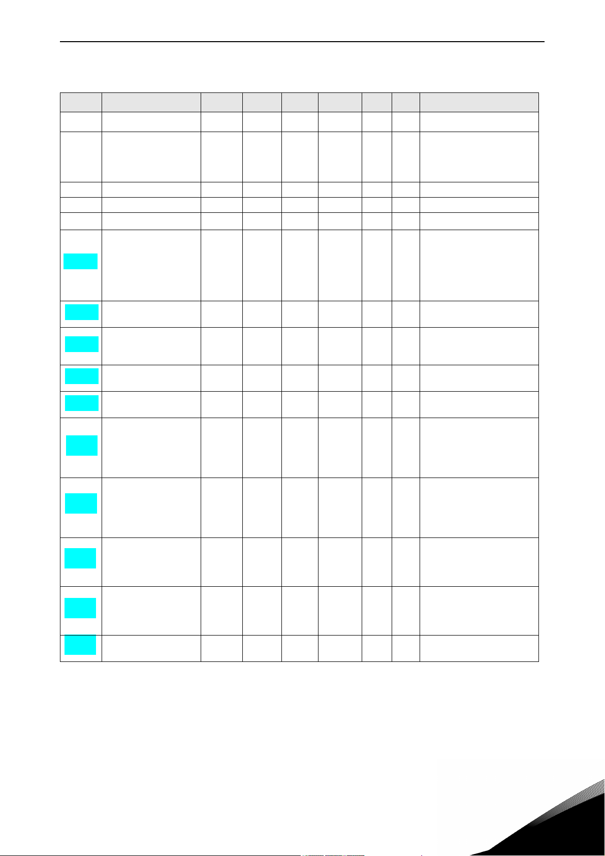
Table 1. Basic application default I/O configuration
OPTA1
Terminal Signal Description
READY
1+10V
2AI1+Analogue input 1
3 AI1- I/O Ground Ground for reference and controls
4 AI2+ Analogue input 2 Analogue input 2 frequency reference
5 AI2- Current range 0—20mA
6 +24V Control voltage output Voltage for switches, etc. max 0.1 A
7 GND I/O ground Ground for reference and controls
8 DIN1 Start forward Contact closed = start forward
9 DIN2 Start reverse Contact closed = start reverse
10 DIN3 External fault input Programma-
11 CMA Common for DIN 1—DIN 3 Connect to GND or +24V
12 +24V Control voltage output Voltage for switches (see #6)
13 GND I/O ground Ground for reference and controls
14 DIN4 Preset speed select 1 DIN4
15 DIN5 Preset speed select 2 Open
16 DIN6 Fault reset Contact open = no action
17 CMB Common for DIN4—DIN6 Connect to GND or +24V
18 AO1+ Analogue output 1
mA
19 AO1-
20 DO1 Digital output 1
OPTA2
21 RO1 Relay output 1
22 RO1
23 RO1
24 RO2 Relay output 2
25 RO2
26 RO2
Reference output Voltage for potentiometer, etc.
ref
Analogue input 1 frequency
Voltage range 0—10V DC
reference
Programmable (P2.14)
Contact open = no fault
ble (P2.17)
Contact closed = fault
DIN5 Frequency ref.
Open
Closed
Open
Closed
Open
Closed
Closed
Contact closed = fault reset
Range 0—20 mA/R
L
Output frequency
Programmable (P2.16)
Open collector, I50mA, U48 VDC
READY
RUN
FAU LT
I/O ref (P2.14)
Preset speed1
Preset speed 2
Max frequency
, max. 500
24-hour support +358 (0)201 212 575 • Email: vacon@vacon.com
Figure 1.
1
Page 8
vacon • 7 Basic Application
DI N4
DI N5
AI1
AI2
DI N1
DI N2
DI N6
DI N3
>1
3.2 Key p ad re fe renc e
3.1 Co ntro l pl ace
Internal frequency
reference
Start forward
Start reverse
Start/Stop and
reverse logic
Start/Stop
Rev ers e
Internal Start/ Stop
Internal reverse
Internal fault reset
Fault r eset input
External fault input (programmable)
Reset button
Start/Stop buttons
Reference from fieldbus
Start/Stop from fieldbus
Direction from fieldbus
3.3 Keypad direction
2.1 4 I/O Ref ere nce
2.19 Preset Speed 2
2.18 Preset Speed 1
2.2 Max Frequenc y
7075.emf
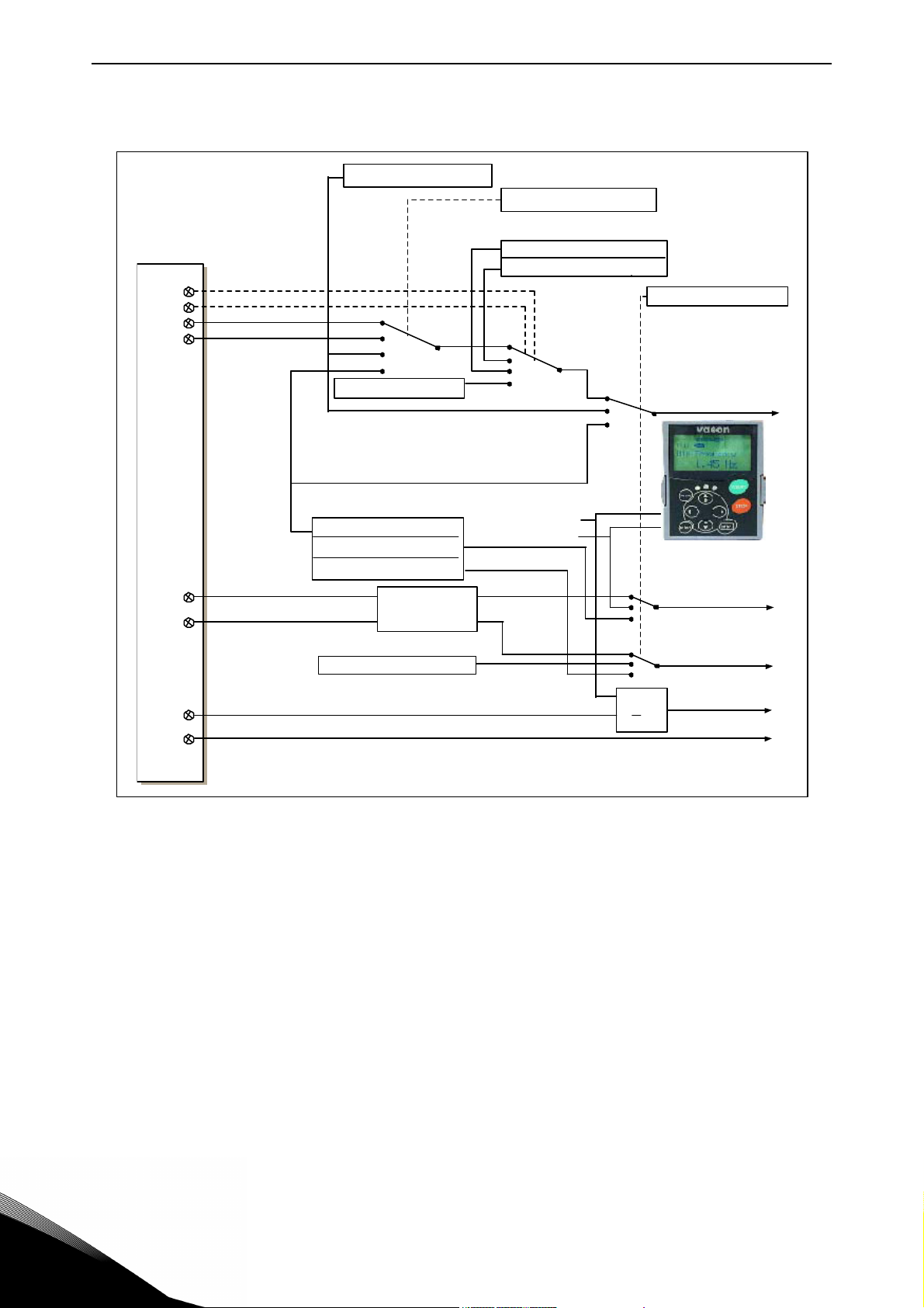
1.3 Control signal logic in Basic Application
Figure 2. Control signal logic of the Basic Application
1
Tel. +358 (0) 201 2121 • Fax +358 (0)201 212 205
Page 9

Basic Application vacon • 8
1.4 Basic Application – Parameter lists
On the next pages you will find the lists of parameters within the respective parameter groups. The
parameter descriptions are given on pages 131 to pages 230.
Column explanations:
Code = Location indication on the keypad; Shows the operator the present parameter number
Parameter = Name of parameter
Min = Minimum value of parameter
Max = Maximum value of parameter
Unit = Unit of parameter value; Given if available
Default = Value preset by factory
Cust = Customer’s own setting
ID = ID number of the parameter
= Parameter value can only be changed after the frequency converter has been stopped.
1.4.1 Monitoring values (Control keypad: menu M1)
The monitoring values are the actual values of parameters and signals as well as statuses and
measurements. Monitoring values cannot be edited.
See the product's User's Manual for more information.
Table 2. Monitoring values
Code Parameter Unit ID Description
V1.1 Output frequency Hz 1 Output frequency to motor
V1.2 Frequency reference Hz 25
V1.3 Motor speed rpm 2 Motor speed in rpm
V1.4 Motor current A 3
V1.5 Motor torque % 4 Calculated shaft torque
V1.6 Motor power % 5 Motor shaft power
V1.7 Motor voltage V 6
V1.8 DC link voltage V 7
V1.9 Unit temperature
V1.10 Motor temperature % 9 Calculated motor temperature
V1.11 Analogue input 1 V/mA 13 AI1
V1.12 Analogue input 2 V/mA 14 AI2
V1.13 DIN1, DIN2, DIN3 15 Digital input statuses
V1.14 DIN4, DIN5, DIN6 16 Digital input statuses
V1.15 DO1, RO1, RO2 17 Digital and relay output statuses
V1.16
M1.17 Multimonitoring items
Analogue I
out
C
mA 26 AO1
Frequency reference to motor
control
8 Heatsink temperature
Displays three selectable monitoring values
24-hour support +358 (0)201 212 575 • Email: vacon@vacon.com
1
Page 10

vacon • 9 Basic Application
1.4.2 Basic parameters (Control keypad: Menu M2 -> G2.1)
Table 3. Basic parameters G2.1
Code Parameter Min Max Unit Default Cust ID Note
P2.1 Min frequency 0,00 P2.2 Hz 0,00 101
NOTE: If f
P2.2 Max frequency P2.1 320,00 Hz 50,00 102
chronous speed, check suitability
for motor and drive system
P2.3 Acceleration time 1 0,1 3000,0 s 3,0 103
P2.4 Deceleration time 1 0,1 3000,0 s 3,0 104
P2.5 Current limit
P2.6
P2.7
Nominal voltage of
the motor
Nominal frequency
of the motor
0,1 x I
2 x I
H
A
H
180 690 V
8,00 320,00 Hz 50,00 111
I
L
NX2:230V
NX5:400V
NX6:690V
107
Check the rating plate of the
110
motor.
Check the rating plate of the
motor.
Check the rating plate of the
motor.
The default applies for a 4-pole
motor and a nominal size fre-
P2.8
Nominal speed of
the motor
24 20 000 rpm 1440 112
quency converter.
P2.9
Nominal current of
the motor
0,1 x I
2 x I
H
A
H
I
H
Check the rating plate of the
113
motor.
P2.10 Motor cos 0,30 1,00 0,85 120 Check the rating plate of the motor
0 = Ramp
P2.11 Start function 0 2 0 505
1 = Flying start
2 = Conditional flying start
0 = Coasting
P2.12 Stop function 0 3 0 506
1 = Ramp
2 = Ramp+Run enable coast
3 = Coast+Run enable ramp
P2.13 U/f optimisation 0 1 0 109
0 = Not used
1 = Automatic torque boost
0 = AI1
P2.14 I/O reference 0 3 0 117
1 = AI2
2 = Keypad
3 = Fieldbus
P2.15
Analogue input 2,
reference offset
0 1 1 302
0 = 0—20mA
1 = 4mA—20 mA
0 = Not used
1 = Output freq. (0—f
2 = Freq. reference (0—f
3 = Motor speed (0—Motor nominal
P2.16
Analogue output
function
0 8 1 307
speed)
4 = Output current (0-I
5 = Motor torque (0—T
6 = Motor power (0—P
7 = Motor voltage (0-U
8 = DC-link volt (0—1000V)
0 = Not used
1 = Ext. fault, closing cont.
2 = Ext. fault, opening cont.
P2.17 DIN3 function 0 7 1 301
3 = Run enable, cc
4 = Run enable, oc
5 = Force cp. to IO
6 = Force cp. to keypad
7 = Force cp. to fieldbus
> than the motor syn-
max
)
max
max
nMotor
nMotor
nMotor
nMotor
)
)
)
)
)
1
Tel. +358 (0) 201 2121 • Fax +358 (0)201 212 205
Page 11

Basic Application vacon • 10
Table 3. Basic parameters G2.1
Code Parameter Min Max Unit Default Cust ID Note
P2.18 Preset speed 1 0,00 P2.2 Hz 0,00 105 Speeds preset by operator
P2.19 Preset speed 2 0,00 P2.2 Hz 50,00 106 Speeds preset by operator
P2.20 Automatic restart 0 1 0 731
0 = Disabled
1 = Enabled
1.4.3 Keypad control (Control keypad: Menu M3)
The parameters for the selection of control place and direction on the keypad are listed below. See
the Keypad control menu in the product's User's Manual.
Table 4.
Code Parameter Min Max Unit Default Cust ID Note
P3.1 Control place 1 3 1 125
P3.2 Keypad reference P2.1 P2.2 Hz
P3.3 Direction (on keypad)
R3.4 Stop button
01 0 123
01 1 114
Keypad control parameters, M3
1 = I/O terminal
2 = Keypad
3 = Fieldbus
Reverse request activated
from the panel
0 = Limited function of Stop
button
1 = Stop button always
enabled
1.4.4 System menu (Control keypad: Menu M6)
For parameters and functions related to the general use of the frequency converter, such as application and language selection, customised parameter sets or information about the hardware and
software, see the product's User's Manual.
1.4.5 Expander boards (Control keypad: Menu M7)
The M7 menu shows the expander and option boards attached to the control board and board-related information. For more information, see the product's User's Manual.
24-hour support +358 (0)201 212 575 • Email: vacon@vacon.com
1
Page 12

vacon • 11 Standard Application
2. STANDARD APPLICATION
Software code: ASFIFF02
2.1 Introduction
Select the Standard Application in menu M6 on page
The Standard Application is typically used in pump and fan applications and conveyors for which the
Basic Application is too limited but where no special features are needed.
• The Standard Application has the same I/O signals and the same control logic as the Basic
Application.
• Digital input DIN3 and all the outputs are freely programmable.
Additional functions:
• Programmable Start/Stop and Reverse signal logic
• Reference scaling
• One frequency limit supervision
• Second ramps and S-shape ramp programming
• Programmable start and stop functions
• DC-brake at stop
• One prohibit frequency area
• Programmable U/f curve and switching frequency
• Autorestart
• Motor thermal and stall protection: Programmable action; off, warning, fault
The parameters of the Standard Application are explained in Chapter 8 of this manual. The explanations are arranged according to the individual ID number of the parameter.
S6.2
.
2
Tel. +358 (0) 201 2121 • Fax +358 (0)201 212 205
Page 13

Standard Application vacon • 12
Reference potentiometer,
1…10 k
Jum p e r b l ock X 3 :
CM A and CMB grounding
CMB co nnected to GN D
CMA connected to GN D
CMB isolated from GN D
CMA isolated from GN D
CMB and CMA
inter nall y connected together,
isolated from GN D
= Factory default
Note: See jumper selections below.
More information in the product's
User's Manual.
7076.emf
RUN
2.2 Control I/O
Table 5. Standard application default I/O configuration
OPTA1
Terminal Signal Description
READY
mA
1 +10V
2 AI1+ Analogue input 1
3 AI1- I/O Ground Ground for reference and controls
4 AI2+ Analogue input 2
5 AI26 +24V Control voltage output Voltage for switches, etc. max 0.1 A
7 GND I/O ground Ground for reference and controls
8 DIN1 Start forward
9DIN2Start reverse
10 DIN3 External fault input Programmable
11 CMA Common for DIN 1—DIN 3 Connect to GND or +24V
12 +24V Control voltage output Voltage for switches (see #6)
13 GND I/O ground Ground for reference and controls
14 DIN4 Preset speed select 1 DIN4 DIN5 Frequency ref.
DIN5 Preset speed select 2 Open
15
16 DIN6 Fault reset Contact open = no action
17 CMB Common for DIN4—DIN6 Connect to GND or +24V
18 AO1+ Analogue output 1
19 AO1-
20 DO1 Digital output 1
OPTA2
21 RO1 Relay output 1
22 RO1
23 RO1
24 RO2 Relay output 2
25 RO2
26 RO2
Reference output Voltage for potentiometer, etc.
ref
Analogue input 1 frequency reference
Voltage range 0—10V DC
Programmable (P2.1.11)
Analogue input 2 frequency reference
Current range 0—20mA
Contact closed = start forward
Programmable logic (P2.2.1)
Contact closed = start reverse
Ri min = 5 kohm
Contact open = no fault
(P2.2.2)
Contact closed = fault
Open
Closed
Open
Closed
Open
Closed
Closed
I/O Reference
Preset Speed 1
Preset Speed 2
Analogue input 2
Contact closed = fault reset
Range 0—20 mA/R
, max. 500
L
Output frequency
Programmable (P2.3.2)
Open collector, I50mA, U48 VDC
READY
Programmable (P2.3.7)
RUN
Programmable (P2.3.8
FAU LT
Programmable (P2.3.9)
24-hour support +358 (0)201 212 575 • Email: vacon@vacon.com
Figure 3.
2
Page 14
vacon • 13 Standard Application
DIN4
DIN5
AI1
AI2
DIN1
DIN2
DIN6
DIN3
>1
3.2Keypadreference
2.1. 11 I/O Ref ere n ce
2.1.12 Keypad Ctrl Reference
2.1. 13 F ie ldbus C trl R eferen ce
2.1. 14 Pre set Spee d 1
2.1. 15 Pre set Spee d 2
3.1 Co n tr o l pla ce
Inte rnal fre quen cy
reference
Start forward
(programmable)
Start reverse (programmable)
Programmable
Start/Stop and
reverse logic
Start/Stop
Rev e rse
Internal Start/Stop
Internal re verse
Inte rnal fau lt reset
Fault reset inp ut
External fault input (programmable)
Reset bu tto n
Start/Stop buttons
Refe r ence f rom fi eldbus
Start/Stop f rom fi eldbu s
Direction from fieldbus
3.3 Keypad direction
7077.emf
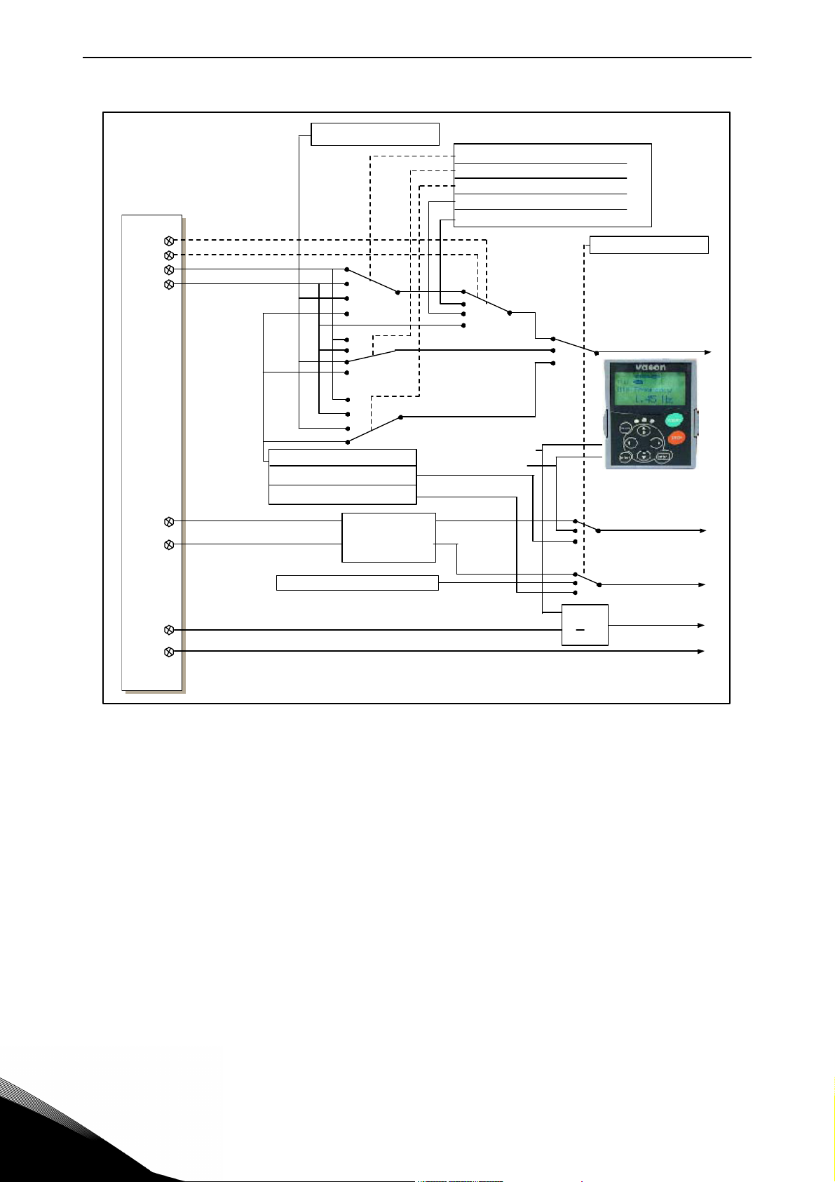
2.3 Control signal logic in Standard Application
Figure 4. Control signal logic of the Standard Application
2
Tel. +358 (0) 201 2121 • Fax +358 (0)201 212 205
Page 15

Standard Application vacon • 14
2.4 Standard Application – Parameter lists
On the next pages you will find the lists of parameters within the respective parameter groups. The
parameter descriptions are given on Pages 131 to230. The descriptions are arranged according to
the ID number of the parameter.
Column explanations:
Code = Location indication on the keypad; Shows the operator the present parameter
number
Parameter = Name of parameter
Min = Minimum value of parameter
Max = Maximum value of parameter
Unit = Unit of parameter value; Given if available
Default = Value preset by factory
Cust = Customer’s own setting
ID = ID number of the parameter
= In parameter row: Use TTF method to program these parameters.
= On parameter code: Parameter value can only be changed after the frequency
converter has been stopped.
2.4.1 Monitoring values (Control keypad: menu M1)
The monitoring values are the actual values of parameters and signals as well as statuses and
measurements. Monitoring values cannot be edited.
See the product's User's Manual for more information.
Table 6. Monitoring values
Code Parameter Unit ID Description
V1.1 Output frequency Hz 1 Output frequency to motor
V1.2 Frequency reference Hz 25 Frequency reference to motor control
V1.3 Motor speed rpm 2 Motor speed in rpm
V1.4 Motor current A 3
V1.5 Motor torque % 4 Calculated shaft torque
V1.6 Motor power % 5 Motor shaft power
V1.7 Motor voltage V 6
V1.8 DC link voltage V 7
V1.9 Unit temperature
V1.10 Motor temperature % 9 Calculated motor temperature
V1.11 Analogue input 1 V/mA 13 AI1
V1.12 Analogue input 2 V/mA 14 AI2
V1.13 DIN1, DIN2, DIN3 15 Digital input statuses
V1.14 DIN4, DIN5, DIN6 16 Digital input statuses
V1.15 DO1, RO1, RO2 17 Digital and relay output statuses
V1.16
M1.17 Monitoring items Displays three selectable monitoring values
Analogue I
out
C
mA 26 AO1
8 Heatsink temperature
24-hour support +358 (0)201 212 575 • Email: vacon@vacon.com
2
Page 16

vacon • 15 Standard Application
2.4.2 Basic parameters (Control keypad: Menu M2 -> G2.1)
Table 7. Basic parameters G2.1
Code Parameter Min Max Unit Default Cust ID Note
P2.1.1 Min frequency 0,00 P2.1.2 Hz 0,00 101
P2.1.2 Max frequency P2.1.1 320,00 Hz 50,00 102
P2.1.3 Acceleration time 1 0,1 3000,0 s 3,0 103
P2.1.4 Deceleration time 1 0,1 3000,0 s 3,0 104
P2.1.5 Current limit
P2.1.6
P2.1.7
P2.1.8
P2.1.9
P2.1.10 Motor cos 0,30 1,00 0,85 120
P2.1.11 I/O reference 0 3 0 117
P2.1.12
P2.1.13
P2.1.14 Preset speed 1 0,00 P2.1.2 Hz 10,00 105
P2.1.15 Preset speed 2 0,00 P2.1.2 Hz 50,00 106
Nominal voltage of
the motor
Nominal frequency
of the motor
Nominal speed of
the motor
Nominal current of
the motor
Keypad control
reference
Fieldbus control
reference
0,1 x I
180 690 V
8,00 320,00 Hz 50,00 111
0,1 x I
2 x I
H
24 20 000 rpm 1440 112
2 x I
H
03 2 121
03 3 122
A
H
A
H
I
L
NX2: 230V
NX5: 400V
NX6: 690V
I
H
107
110
113
NOTE: If f
synchronous speed, check suit-
ability for motor and drive system
Check the rating plate of the
motor
The default applies for a 4-pole
motor and a nominal size frequency converter.
Check the rating plate of the
motor.
Check the rating plate of the
motor
0 = AI1
1 = AI2
2 = Keypad
3 = Fieldbus
0 = AI1
1= AI2
2 = Keypad
3 = Fieldbus
0 = AI1
1 = AI2
2 = Keypad
3 = Fieldbus
Speeds preset by operator
> than the motor
max
2
Tel. +358 (0) 201 2121 • Fax +358 (0)201 212 205
Page 17

Standard Application vacon • 16
2.4.3 Input signals (Control keypad: Menu M2 -> G2.2)
Table 8. Input signals, G2.2
Code Parameter Min Max Unit Default Cust ID Note
DIN 1 DIN2
0
Start fwd
1
Start/Stop
2
Start/Stop
P2.2.1 Start/Stop logic 0 6 0 300
P2.2.2 DIN3 function 0 8 1 301
P2.2.3
P2.2.4
P2.2.5
P2.2.6 Reference inversion 0 1 0
P2.2.7 Reference filter time 0,00 10,00 s 0,10 306 0 = No filtering
P2.2.8 AI1 signal selection A1 377
P2.2.9 AI2 signal selection A2 388
Analogue input 2
reference offset
Reference scaling
minimum value
Reference scaling
maximum value
0 1 1 302
0,00
320,00 Hz 0,00
0,00
320,00 Hz 0,00 304
3
Start pulse
4
Start fwd*
5
Start*/Stop
6
Start*/Stop
0 = Not used
1 = Ext. fault, closing cont.
2 = Ext. fault, opening cont.
3 = Run enable
4 = Acc./Dec. time select.
5 = Force cp. to IO
6 = Force cp. to keypad
7 = Force cp. to fieldbus
8 = Reverse
0 = 0—20mA (0—10V)**
1 = 4—20mA (2—10V)**
Selects the frequency that cor-
303
responds to the min. reference
signal
0,00 = No scaling
Selects the frequency that corresponds to the max. reference signal
0,00 = No scaling
305 0 = Not inverted
1 = Inverted
TTF programming method
used. See page 72.
TTF programming method
used. See page 72.
Start rvs
Rvs/Fwd
Run enable
Stop pulse
Start rvs*
Rvs/Fwd
Run enable
* = Rising edge required to start
** = Remember to place jumpers of block X2 accordingly. See the product’s User Manual
24-hour support +358 (0)201 212 575 • Email: vacon@vacon.com
2
Page 18

vacon • 17 Standard Application
2.4.4 Output signals (Control keypad: Menu M2 -> G2.3)
Table 9. Output signals, G2.3
Code Parameter Min Max Unit Default Cust ID Note
P2.3.1
P2.3.2 Analogue output function 0 8 1 307
P2.3.3 Analogue output filter time 0,00 10,00 s 1,00 308 0 = No filtering
P2.3.4 Analogue output inversion 0 1 0 309
P2.3.5 Analogue output minimum 0 1 0 310
P2.3.6 Analogue output scale 10 1000 % 100 311
P2.3.7 Digital output 1 function 0 16 1 312
P2.3.8 RO1 function 0 16 2 313 As parameter 2.3.7
P2.3.9 RO2 function 0 16 3 314 As parameter 2.3.7
P2.3.10
P2.3.11
P2.3.12
P2.3.13 Analogue output 2 function 0 8 4 472 As parameter 2.3.2
P2.3.14
P2.3.15
P2.3.16
P2.3.17 Analogue output 2 scaling 10 1000 % 1,00 476
Analogue output 1 signal
selection
Output frequency limit 1
supervision
Output frequency limit 1;
Supervised value
Analogue output 2 signal
selection
Analogue output 2 filter
time
Analogue output 2 inver-
sion
Analogue output 2 mini-
mum
0 A.1
0 2 0 315
0,00
0,00 10,00 s
320,00 Hz 0,00 316
0.1 E.10
0
0
1
1
0.1 471
1,00
0 474
0 475
464 TTF programming method
used. See page 72 .
0 = Not used (20 mA/10 V)
1 = Output freq. (0—f
2 = Freq. reference (0—f
3 = Motor speed (0—Motor
nominal speed)
4 = Motor current (0—I
5 = Motor torque (0—T
6 = Motor power (0—P
7 = Motor voltage (0--U
8 = DC-link volt (0—1000V)
0 = Not inverted
1 = Inverted
0 = 0 mA (0 V)
1 = 4 mA (2 V)
0 = Not used
1 = Ready
2 = Run
3 = Fault
4 = Fault inverted
5 = FC overheat warning
6 = Ext. fault or warning
7 = Ref. fault or warning
8 = Warning
9 = Reversed
10 = Preset speed 1
11 = At speed
12 = Mot. regulator active
13 = OP freq. limit 1 superv.
14 = Control place: IO
15 = Thermistor fault/warng
16 = Fieldbus DIN1
0 = No limit
1 = Low limit supervision
2 = High limit supervision
TTF programming method
used. See page 72.
473 0 = No filtering
0 = Not inverted
1 = Inverted
0 = 0 mA (0 V)
1 = 4 mA (2 V)
max
nMotor
nMotor
nMotor
)
max
nMotor
)
)
)
)
)
2
Tel. +358 (0) 201 2121 • Fax +358 (0)201 212 205
Page 19

Standard Application vacon • 18
2.4.5 Drive control parameters (Control keypad: Menu M2 -> G2.4)
Table 10. Drive control parameters, G2.4
Code Parameter Min Max Unit Default Cust ID Note
P2.4.1 Ramp 1 shape 0,0 10,0 s 0,1 500
P2.4.2 Ramp 2 shape 0,0 10,0 s 0,0 501
P2.4.3 Acceleration time 2 0,1 3000,0 s 10,0 502
P2.4.4 Deceleration time 2 0,1 3000,0 s 10,0 503
P2.4.5 Brake chopper 0 4 0 504
P2.4.6 Start function 0 2 0 505
P2.4.7 Stop function 0 3 0 506
P2.4.8 DC braking current 0,00
P2.4.9
P2.4.10
P2.4.11
P2.4.12 Flux brake 0 1 0 520
P2.4.13 Flux braking current 0,00
DC braking time
at stop
Frequency to start DC
braking during
ramp stop
DC braking time
at start
0,00 600,00 s 0,00 508 0 = DC brake is off at stop
0,10 10,00 Hz 1,50 515
0,00 600,00 s 0,00 516 0 = DC brake is off at start
I
L
I
L
0,7 x I
A
A
H
I
H
507
519
0 = Linear
>0 = S-curve ramp time
0 = Linear
>0 = S-curve ramp time
0 = Disabled
1 = Used when running
2 = External brake chopper
3 = Used when stopped/ running
4 = Used when running (no testing)
0 = Ramp
1 = Flying start
2 = Conditional flying start
0 = Coasting
1 = Ramp
2 = Ramp+Run enable coast
3 = Coast+Run enable ramp
0 = Off
1 = On
24-hour support +358 (0)201 212 575 • Email: vacon@vacon.com
2
Page 20

vacon • 19 Standard Application
2.4.6 Prohibit frequency parameters (Control keypad: Menu M2 -> G2.5)
Table 11. Prohibit frequency parameters, G2.5
Code Parameter Min Max Unit Default Cust ID Note
P2.5.1
P2.5.2
P2.5.2
Prohibit frequency
range 1 low limit
Prohibit frequency
range 1 high limit
Prohibit acc./dec.
ramp
0,00 320,00
0,00 320,00
0,1
10,0 x
Hz
Hz
0,00 509
0,00 510
1,0 518
2.4.7 Motor control parameters (Control keypad: Menu M2 -> G2.6)
Table 12. Motor control parameters, G2.6
Code Parameter Min Max Unit Default Cust ID Note
0 = Frequency control
1 = Speed control
P2.6.1 Motor control mode 0 1/3 0 600
P2.6.2 U/f optimisation 0 1 0 109
P2.6.3 U/f ratio selection 0 3 0 108
P2.6.4 Field weakening point 8,00 320,00 Hz 50,00 602
P2.6.5
P2.6.6
P2.6.7
P2.6.8
P2.6.9 Switching frequency 1,0 Varies kHz Varies 601 See 8-14 for exact values
P2.6.10 Overvoltage controller 0 2 1 607
P2.6.11
P2.6.12 Load drooping 0,00 100,00 % 0,00 620
P2.6.13 Identification 0 1/2 0 631
Voltage at field weak-
ening point
U/f curve midpoint fre-
quency
U/f curve midpoint
voltage
Output voltage at zero
frequency
Undervoltage control-
ler
10,00 200,00 % 100,00 603
0,00 P2.6.4 Hz 50,00 604
0,00 100,00 % 100,00 605
0,00 40,00 % Varies 606
01 1
Additionally for NXP:
2 = Not used
3 = Closed loop speed ctrl
0 = Not used
1 = Automatic torque boost
0 = Linear
1 = Squared
2 = Programmable
3 = Linear with flux optim
n% x U
nmot
n% x U
nmot
Parameter max. value =
P2.6.5
n% x U
nmot
0 = Not used
1 = Used (no ramping)
2 = Used (ramping)
608 0 = Not used
1 = Used
0 = No action
1 = Identification w/o run
2 = Identification with run
2
Closed Loop parameter group 2.6.14
P2.6.14.1 Magnetizing current 0,00
P2.6.14.2 Speed control P gain 1 1000 30 613
P2.6.14.3 Speed control I time 0,0 3200,0 ms 30,0 614
P2.6.14.5
P2.6.14.6 Slip adjust 0 500 % 100 619
Acceleration compen-
sation
0,00 300,00 s 0,00 626
2 x I
A 0,00 612
H
Tel. +358 (0) 201 2121 • Fax +358 (0)201 212 205
Page 21

Standard Application vacon • 20
Table 12. Motor control parameters, G2.6
Code Parameter Min Max Unit Default Cust ID Note
P2.6.14.7
P2.6.14.8
P2.6.14.9 0-speed time at start 0 32000 ms 100 615
P2.6.14.10 0-speed time at stop 0 32000 ms 100 616
P2.6.14.11 Start-up torque 0 32000 0 621
P2.6.14.12
Magnetizing current at
start
Magnetizing time at
start
Start-up torque FWD
0,00
0 60000 ms 0 628
–300,0 3 % 0,0 633
I
L
A 0,00 627
0 = Not used
1 = Torque memory
2 = Torque reference
3 = Start-up torque fwd/rev
P2.6.14.13 Start-up torque REV –300,0
P2.6.14.15 Encoder filter time 0,0 100,0 ms 0,0 618
P2.6.14.17
Current control
P gain
0,00 100,00 % 40,00
300,0
% 0,0 634
617
Identification parameter group 2.6.15
P2.6.15.1 Speed step -50,0 50,0 0,0 0,0 1252 NCDrive speed tuning
2.4.8 Protections (Control keypad: Menu M2 -> G2.7)
Table 13. Protections, G2.7
Code Parameter Min Max Unit Default Cust ID Note
0 = No response
1 = Warning
P2.7.1
P2.7.2
P2.7.3 Response to external fault 0 3 2 701 0 = No response
P2.7.4 Input phase supervision 0 3 0 730
P2.7.5
P2.7.6 Output phase supervision 0 3 2 702
P2.7.7 Earth fault protection 0 3 2 703
P2.7.8
P2.7.9
P2.7.10
P2.7.11 Motor thermal time constant 1 200 min Varies 707
P2.7.12 Motor duty cycle 0 150 % 100 708
Response to 4mA reference
fault
4mA reference fault fre-
quency
Response to undervoltage
fault
Thermal protection of the
motor
Motor ambient temperature
factor
Motor cooling factor at zero
speed
05 0 700
0,00 P2.1.2 Hz 0,00 728
01 0 727
03 2 704
–100,0 100,0 % 0,0 705
0,0 150,0 % 40,0 706
2 = Warning+Previous Freq.
3 = Wrng+PresetFreq 2.7.2
4 = Fault, stop acc. to 2.4.7
5 = Fault, stop by coasting
1 = Warning
2 = Fault, stop acc. to 2.4.7
3 = Fault, stop by coasting
0 = Fault stored in history
1 = Fault not stored
0 = No response
1 = Warning
2 = Fault, stop acc. to 2.4.7
3 = Fault, stop by coasting
24-hour support +358 (0)201 212 575 • Email: vacon@vacon.com
2
Page 22

vacon • 21 Standard Application
Table 13. Protections, G2.7
Code Parameter Min Max Unit Default Cust ID Note
0 = No response
P2.7.13 Stall protection 0 3 0 709
P2.7.14 Stall current 0,00
P2.7.15 Stall time limit 1,00 120,00 s 15,00 711
P2.7.16 Stall frequency limit 1,0 P2.1.2 Hz 25,0 712
P2.7.17 Underload protection 0 3 0 713
P2.7.18 Field weakening area load 10 150 % 50 714
P2.7.19 Zero frequency load 5,0 150,0 % 10,0 715
P2.7.20
P2.7.21 Response to thermistor fault 0 3 2 732
P2.7.22 Response to fieldbus fault 0 3 2 733 See P2.7.21
P2.7.23 Response to slot fault 0 3 2 734 See P2.7.21
Underload protection time
limit
2 x I
2 600 s 20 716
A
H
I
H
1 = Warning
2 = Fault, stop acc. to 2.4.7
3 = Fault, stop by coasting
710
0 = No response
1 = Warning
2 = Fault,stop acc. to 2.4.7
3 = Fault,stop by coasting
0 = No response
1 = Warning
2 = Fault, stop acc. to 2.4.7
3 = Fault, stop by coasting
2
Tel. +358 (0) 201 2121 • Fax +358 (0)201 212 205
Page 23
Standard Application vacon • 22
2.4.9 Autorestart parameters (Control keypad: Menu M2 -> G2.8)
Table 14. Autorestart parameters, G2.8
Code Parameter Min Max Unit Default Cust ID Note
P2.8.1 Wait time 0,10 10,00 s 0,50 717
P2.8.2 Trial time 0,00 60,00 s 30,00 718
0 = Ramp
P2.8.3 Start function 0 2 0 719
P2.8.4 Number of tries after undervoltage trip 0 10 0 720
P2.8.5 Number of tries after overvoltage trip 0 10 0 721
P2.8.6 Number of tries after overcurrent trip 0 3 0 722
P2.8.7 Number of tries after 4mA reference trip 0 10 0 723
P2.8.8
P2.8.9 Number of tries after external fault trip 0 10 0 725
P2.8.10
Number of tries after motor temperature
fault trip
Number of tries after underload fault
trip
010 0 726
010 0 738
1 = Flying start
2 = According to P2.4.6
2.4.10 Keypad control (Control keypad: Menu M3)
The parameters for the selection of control place and direction on the keypad are listed below. See
the Keypad control menu in the product's User's Manual.
Table 15. Keypad control parameters, M3
Code Parameter Min Max Unit Default Cust ID Note
1 = I/O terminal
P3.1 Control place 1 3 1 125
R3.2 Keypad reference P2.1.1 P2.1.2 Hz
P3.3 Direction (on keypad) 0 1 0 123
R3.4 Stop button 0 1 1 114
2 = Keypad
3 = Fieldbus
0 = Forward
1 = Reverse
0 = Limited function of Stop button
1 = Stop button always enabled
24-hour support +358 (0)201 212 575 • Email: vacon@vacon.com
2
Page 24

vacon • 23 Standard Application
2.4.11 System menu (Control keypad: M6)
For parameters and functions related to the general use of the frequency converter, such as application and language selection, customised parameter sets or information about the hardware and
software, see the product's User's Manual.
2.4.12 Expander boards (Control keypad: Menu M7)
The M7 menu shows the expander and option boards attached to the control board and board-related information. For more information, see the product's User's Manual.
2
Tel. +358 (0) 201 2121 • Fax +358 (0)201 212 205
Page 25

Local/Remote Control Application vacon • 24
3. LOCAL/REMOTE CONTROL APPLICATION
Software code: ASFIFF03
3.1 Introduction
Select the Local/Remote Control Application in menu M6 on page
Utilising the Local/Remote Control Application it is possible to have two different control places.
For each control place the frequency reference can be selected from either the control keypad, I/O
terminal or fieldbus. The active control place is selected with the digital input DIN6.
• All outputs are freely programmable.
Additional functions:
• Programmable Start/Stop and Reverse signal logic
• Reference scaling
• One frequency limit supervision
• Second ramps and S-shape ramp programming
• Programmable start and stop functions
• DC-brake at stop
• One prohibit frequency area
• Programmable U/f curve and switching frequency
• Autorestart
• Motor thermal and stall protection: Programmable action; off, warning, fault
The parameters of the Local/Remote Control Application are explained in Chapter 8 of this manual.
The explanations are arranged according to the individual ID number of the parameter.
S6.2
.
24-hour support +358 (0)201 212 575 • Email: vacon@vacon.com
3
Page 26

vacon • 25 Local/Remote Control Application
Reference potentiometer,
1…10 k
Ju m p er b lo ck X 3 :
CM A and CMB grounding
CMB connected to GND
CM A connected to G ND
CMB isolated from GN D
CMA i solated from GN D
CMB and CMA
internally connected together,
isolated from GN D
= Factory default
Note: See jumper selections below.
More information in the product's
User's Manual.
7078.emf
RUN
3.2 Control I/O
Table 16. Local/Remote control application default I/O configuration.
OPTA1
Ter min al Signal Description
Remote Reference
0(4) - 20 mA
Remote Control ground
READY
mA
1 +10V
2AI1+Analogue input 1
3 AI1- I/O Ground Ground for reference and controls
4AI2+Analogue input 2
5AI2-
6 +24V Control voltage output Voltage for switches, etc. max 0.1 A
7 GND I/O ground Ground for reference and controls
8 DIN1 Place A: Start forward
9DIN2Place A: Start reverse
10 DIN3 External fault input Programmable
11 CMA Common for DIN 1—DIN 3 Connect to GND or +24V
12 +24V Control voltage output Voltage for switches (see #6)
13 GND I/O ground Ground for reference and controls
14 DIN4 Place B: Start forward
15 DIN5 Place B: Start reverse
16 DIN6 Place A/B selection Contact open = place A is active
17 CMB Common for DIN4—DIN6 Connect to GND or +24V
18 AO1+ Analogue output 1
19 AO1-
20 DO1 Digital output
OPTA2
21 RO1 Relay output 1
22 RO1
23 RO1
24 RO2 Relay output 2
25 RO2
26 RO2
Reference output Voltage for potentiometer, etc.
ref
Analogue input 1 reference for
Voltage range 0—10V DC
place B
Programmable (P2.1.12)
Analogue input 2 reference for
Current range 0—20mA
place A
Programmable (P2.1.11)
Contact closed = start forward
Programmable logic (P2.2.1)
Contact closed = start reverse
Ri min = 5 kohm
Contact open = no fault
(P2.2.2)
Contact closed = fault
Contact closed = start for-
Programmable logic (P2.2.15)
ward
Ri min = 5 kohm
Contact closed = start reverse
Contact closed = Place B is active
Range 0—20 mA/R
Output frequency
Programmable (P2.3.2)
Open collector, I50mA, U48 VDC
READY
Programmable (P2.3.7)
RUN
Programmable (P2.3.8)
FAU LT
Programmable (P2.3.9)
, max. 500
L
3
Figure 5.
Tel. +358 (0) 201 2121 • Fax +358 (0)201 212 205
Page 27
Local/Remote Control Application vacon • 26
DIN3
>1
DIN6
DIN2
DIN3
AI1
AI2
DIN1
DIN2
DIN3
DIN4
DIN5
A
B
A
B
A
B
Inte rnal re ve rse
Internal fault reset
Fa ult res e t in put (pro gram mabl e)
3.3 Key pad direc ti o n
Inte rna l Start /Stop
Reference from fieldbu s
Start/Sto p from fieldbu s
Direction from fieldb us
St art/ St op bu ttons
Internal
fr equ ency ref .
Reset button
Pr ogra mm able
Start/Sto p and
re ver se l og ic A
Pr ogra mm able
Start/Sto p and
re ver se l og ic B
Start forward
(pro grammable)
Start reverse
(programmable)
St art f or ward
Start rever se
( prog ramma ble )
( prog ramma ble )
Start/Stop
Revers e
Up
Down
3.1 C on tro l pla ce
2. 1.1 5 Jo ggi ng spe ed ref .
2.1.14 F i eldb us C trl r efer en c e
2.1.13 K eypa d C trl referen ce
2. 1. 12 I /O B refe renc e
2.1.11 I/O A refer ence
R3.2 Keypad referen ce
Moto r
potentiomete r
7079.emf
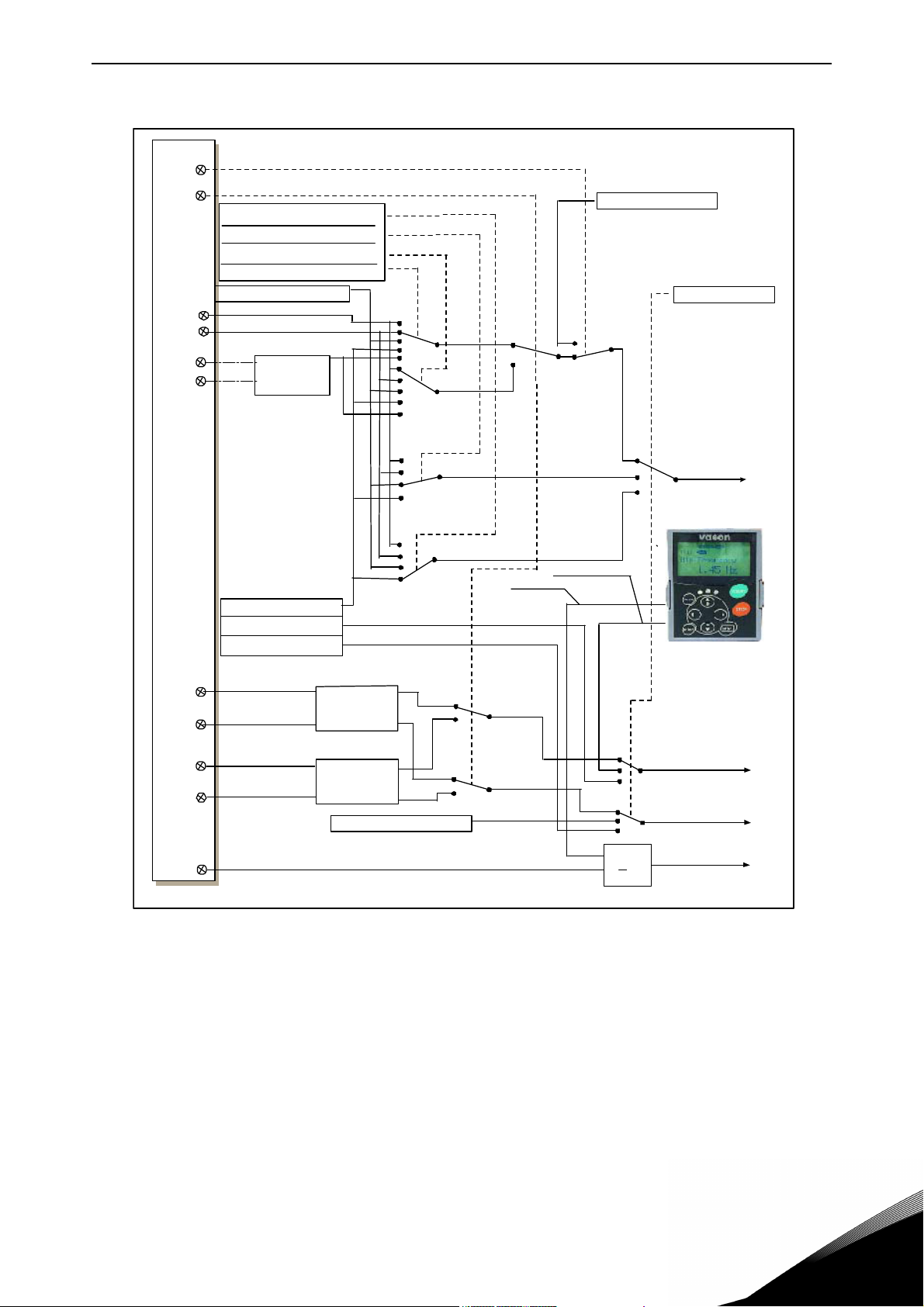
3.3 Control signal logic in Local/Remote Application
Figure 6. Control signal logic of the Local/Remote Control Application
24-hour support +358 (0)201 212 575 • Email: vacon@vacon.com
3
Page 28

vacon • 27 Local/Remote Control Application
3.4 Local/Remote control application – Parameter lists
On the next pages you will find the lists of parameters within the respective parameter groups. The
parameter descriptions are given on pages 131 to 229.
Column explanations:
Code = Location indication on the keypad; Shows the operator the present parameter
number
Parameter = Name of parameter
Min = Minimum value of parameter
Max = Maximum value of parameter
Unit = Unit of parameter value; Given if available
Default = Value preset by factory
Cust = Customer’s own settings
ID = ID number of the parameter
= In parameter row: Use TTF method to program these parameters.
= On parameter number: Parameter value can only be changed after the frequency
converter has been stopped.
3.4.1 Monitoring values (Control keypad: menu M1)
The monitoring values are the actual values of parameters and signals as well as statuses and
measurements. Monitoring values cannot be edited. See the product's User's Manual for more information.
Table 17. Monitoring values
Code Parameter Unit ID Description
V1.1 Output frequency Hz 1 Output frequency to motor
V1.2 Frequency reference Hz 25
V1.3 Motor speed rpm 2 Motor speed in rpm
V1.4 Motor current A 3
V1.5 Motor torque % 4 Calculated shaft torque
V1.6 Motor power % 5 Motor shaft power
V1.7 Motor voltage V 6
V1.8 DC link voltage V 7
V1.9 Unit temperature
V1.10 Motor temperature % 9
V1.11 Analogue input 1 V/mA 13 AI1
V1.12 Analogue input 2 V/mA 14 AI2
C
Frequency reference to
motor control
8Heatsink temperature
Calculated motor
temperature
3
V1.13 DIN1, DIN2, DIN3 15 Digital input statuses
V1.14 DIN4, DIN5, DIN6 16 Digital input statuses
V1.15 DO1, RO1, RO2 17
V1.16
M1.17
Analogue I
Multimonitoring
items
out
mA 26 AO1
Digital and relay output
statuses
Displays three selectable
monitoring values
Tel. +358 (0) 201 2121 • Fax +358 (0)201 212 205
Page 29
Local/Remote Control Application vacon • 28
3.4.2 Basic parameters (Control keypad: Menu M2 -> G2.1)
Table 18. Basic parameters G2.1
Code Parameter Min Max Unit Default Cust ID Note
P2.1.1 Min frequency 0,00 P2.1.2 Hz 0,00 101
P2.1.2 Max frequency P2.1.1 320,00 Hz 50,00 102
P2.1.3 Acceleration time 1 0,1 3000,0 s 3,0 103
P2.1.4 Deceleration time 1 0,1 3000,0 s 3,0 104
P2.1.5 Current limit
P2.1.6
P2.1.7
P2.1.8
P2.1.9
P2.1.10 Motor cos 0,30 1,00 0,85 120
P2.1.11 I/O A reference 0 4 1 117
P2.1.12 I/O B reference 0 4 0 131
P2.1.13
P2.1.14
P2.1.15
Nominal voltage of the
motor
Nominal frequency of
the motor
Nominal speed of the
motor
Nominal current of the
motor
Keypad control refer-
ence
Fieldbus control refer-
ence
Jogging speed refer-
ence
0,1 x I
180 690 V
8,00 320,00 Hz 50,00 111
24 20 000 rpm 1440 112
0,1 x I
03 2 121
03 3 122
0,00 P2.1.2 Hz 0,00 124
2 x I
H
2 x I
H
A
H
A
H
I
L
NX2:
230V
NX5:
400V
NX6:
690V
I
H
107
110
113
NOTE: If f
motor synchronous speed,
check suitability for motor
and drive system
Check the rating plate of
the motor
The default applies for a 4pole motor and a nominal
size frequency converter.
Check the rating plate of
the motor.
Check the rating plate of
the motor
0 = AI1
1 = AI2
2 = Keypad
3 = Fieldbus
4 = Motor potentiometer
0 = AI1
1 = AI2
2 = Keypad
3 = Fieldbus
4 = Motor potentiometer
0 = AI1
1 = AI2
2 = Keypad
3 = Fieldbus
0 = AI1
1 = AI2
2 = Keypad
3 = Fieldbus
> than the
max
24-hour support +358 (0)201 212 575 • Email: vacon@vacon.com
3
Page 30

vacon • 29 Local/Remote Control Application
3.4.3 Input signals (Control keypad: Menu M2 -> G2.2)
Table 19. Input signals, G2.2
Code Parameter Min Max Unit Default Cust ID Note
P2.2.1
P2.2.2 DIN3 function 0 13 1 301
P2.2.3 AI1 signal selection 0.1 E.10 A.1 377
P2.2.4 AI1 signal range 0 2 0 320
P2.2.5
P2.2.6
P2.2.7 AI1 signal inversion 0 1 0 323
P2.2.8 AI1 signal filter time 0,00 10,00 s 0,10 324
P2.2.9 AI2 signal selection 0.1 E.10 A.2 388
P2.2.10 AI2 signal range 0 2 1 325
P2.2.11
P2.2.12
P2.2.13 AI2 signal inversion
Place A Start/Stop
logic selection
AI1 custom setting
minimum
AI1 custom setting
maximum
AI2 custom setting
minimum
AI2 custom setting
maximum
0 8 0 300
-160,00 160,00 % 0,00 321
-160,00 160,00 % 100,0 322
-160,00 160,00
-160,00 160,00
0
% 0,00 326
% 100,00 327
1 0 328
DIN1
0
Start fwd
1
Start/Stop
2
Start/Stop
3
Start pulse
4
Start fwd
5
Start fwd*
6
Start*/Stop
7
Start*/Stop
8
Start fwd*
0 = Not used
1 = Ext. fault, closing cont.
2 = Ext. fault, opening cont.
3 = Run enable
4 = Acc./Dec. time select.
5 = Force cp. to IO
6 = Force cp. to keypad
7 = Force cp. to fieldbus
8 = Reverse
9 = Jogging speed
10 = Fault reset
11 = Acc./Dec. operation
prohibit
12 = DC Braking command
13 = Motor potentiometer
DOWN
TTF programming method used.
See page 72.
0 = 0—10 V (0 – 20 mA**)
1 = 2 – 10 V (4 – 20 mA**)
2 = Custom setting range**
Analogue input 1 scale minimum
Analogue input 1 scale maximum
Analogue input 1 reference
inversion yes/no
Analogue input 1 reference filter
time, constant
TTF programming method used.
See page 72.
0 = 0 – 20 mA (0—10 V **)
1 = 4 – 20 mA (2 – 10 V **)
2 = Custom setting range
Analogue input 2 scale minimum
Analogue input 2 scale maximum
Analogue input 2 reference
inversion yes/no
DIN2
Start rvs
Reverse
Run enable
Stop pulse
Mot.pot.UP
Start rvs*
Reverse
Run enable
Mot.pot.UP
3
P2.2.14 AI2 signal filter time 0,00 10,00 s 0,10 329
Tel. +358 (0) 201 2121 • Fax +358 (0)201 212 205
Analogue input 2 reference filter
time, constant
Page 31

Local/Remote Control Application vacon • 30
Table 19. Input signals, G2.2
Code Parameter Min Max Unit Default Cust ID Note
DIN4 DIN5
0
P2.2.15
P2.2.16
P2.2.17
P2.2.18
P2.2.19
P2.2.20
P2.2.21
P2.2.22
P2.2.23
P2.2.24 Start pulse memory 0 1 0 498
Place B Start/Stop
logic selection
Place A Reference
scaling minimum
value
Place A Reference
scaling maximum
value
Place B Reference
scaling minimum
value
Place B Reference
scaling maximum
value
Free analogue input,
signal selection
Free analogue input,
function
Motor potentiometer
ramp time
Motor potentiometer
frequency reference
memory reset
0 6 0 363
0,00 320,00 Hz 0,00 303
0,00 304
0,00 320,00 Hz 0,00 364
0,00 320,00 Hz 0,00 365
0 2 0 361
0 4 0 362
0,1 2000,0 Hz/s 10,0 331
0 2 1 367
Start fwd
1
Start/Stop
2
Start/Stop
3
Start pulse
4
Start fwd*
5
Start*/Stop
6
Start*/Stop
Selects the frequency that corresponds to the min. reference
signal
Selects the frequency that corresponds to the max. reference
signal
0,00 = No scaling
>0 = scaled max. value
Selects the frequency that corresponds to the min. reference
signal
Selects the frequency that corresponds to the max. reference
signal
0,00 = No scaling
>0 = scaled max. value
0 = Not used
1 = Analogue input 1
2 = Analogue input 2
0 = No function
1 = Reduces current limit
(P2.1.5)
2 = Reduces DC braking
current
3 = Reduces accel. and
decel. times
4 = Reduces torque super
vision limit
0 = No reset
1 = Reset if stopped or pow
ered down
= Reset if powered down
2
0 = Run state not copied
1 = Run state copied
Start rvs
Reverse
Run enable
Stop pulse
Start rvs*
Reverse
Run enable
* = Rising edge required to start
** = Remember to place jumpers of block X2 accordingly. See the product's User's Manual.
24-hour support +358 (0)201 212 575 • Email: vacon@vacon.com
3
Page 32

vacon • 31 Local/Remote Control Application
3.4.4 Output signals (Control keypad: Menu M2 -> G2.3)
Table 20. Output signals, G2.3
Code Parameter Min Max Unit Default Cust ID Note
P2.3.1 AO1 signal selection 0.1 E.10 A.1 464
P2.3.2
P2.3.3 Analogue output filter time 0,00 10,00 s 1,00 308 0 = No filtering
P2.3.4 Analogue output inversion 0 1 0 309
P2.3.5 Analogue output minimum 0 1 0 310
P2.3.6 Analogue output scale 10 1000 % 100 311
P2.3.7 Digital output 1 function 0 22 1 312
P2.3.8 Relay output 1 function 0 22 2 313 As parameter 2.3.7
P2.3.9 Relay output 2 function 0 22 3 314 As parameter 2.3.7
P2.3.10
P2.3.11
P2.3.12
P2.3.13
Analogue output function
Output frequency limit 1
supervision
Output frequency limit 1;
Supervision value
Output frequency limit 2
supervision
Output frequency limit 2;
Supervision value
0 8 1 307
0 2 0 315
0,00 320,00 Hz 0,00 316
0 2 0 346
0,00 320,00 Hz 0,00 347
TTF programming method used.
See page 72.
0 = Not used (20 mA / 10 V)
1 = Output freq. (0—f
2 = Freq. reference (0—f
3 = Motor speed (0—Motor nominal
speed)
4 = Motor current (0—I
5 = Motor torque (0—T
6 = Motor power (0—P
7 = Motor voltage (0-U
8 = DC-link volt (0—1000V)
0 = Not inverted
1 = Inverted
0 = 0 mA
1 = 4 mA
0 = Not used
1 = Ready
2 = Run
3 = Fault
4 = Fault inverted
5 = FC overheat warning
6 = Ext. fault or warning
7 = Ref. fault or warning
8 = Warning
9 = Reversed
10 = Jogging spd selected
11 = At speed
12 = Mot. regulator active
13 = OP freq.limit superv. 1
14 = OP freq.limit superv. 2
15 = Torque limit superv.
16 = Ref. limit superv.
17 = Ext. brake control
18 = Control place: IO
19 = FC temp. limit superv.
20 = Unrequested rotation direc
tion
21 = Ext. brake control inverted
22 = Thermistor fault/warn.
0 = No limit
1 = Low limit supervision
2 = High limit supervision
0 = No limit
1 = Low limit supervision
2 = High limit supervision
max
nMotor
nMotor
nMotor
nMotor
)
max
)
)
)
)
)
3
Tel. +358 (0) 201 2121 • Fax +358 (0)201 212 205
Page 33

Local/Remote Control Application vacon • 32
Table 20. Output signals, G2.3
Code Parameter Min Max Unit Default Cust ID Note
P2.3.14
P2.3.15
P2.3.16
P2.3.17
P2.3.18 External brake Off-delay 0,0 100,0 s 0,5 352
P2.3.19 External brake On-delay 0,0 100,0 s 1,5 353
P2.3.20
P2.3.21
P2.3.22 Analogue output 2 scaling 0.1 E.10 0.1 471
P2.3.23 Analogue output 2 function 0 8 4 472 As parameter 2.3.2
P2.3.24 Analogue output 2 filter time 0,00 10,00 s 1,00 473 0 = No filtering
P2.3.25 Analogue output 2 inversion 0 1 0 474
P2.3.26 Analogue output 2 minimum 0 1 0 475
P2.3.27 Analogue output 2 scaling 10 1000 % 100 476
Torque limit supervision
function
Torque limit supervision
value
Reference limit supervision
function
Reference limit supervision
value
Frequency converter temperature limit supervision
Frequency converter
temperature limit value
0 2 0 348
-300,0 300,0 % 0,0 349
0 2 0 350
0,0 100,0 % 0,0 351
0 2 0 354
-10 100 C 40 355
0 = No
1 = Low limit
2 = High limit
0 = No
1 = Low limit
2 = High limit
0 = No
1 = Low limit
2 = High limit
TTF programming method used.
See page 72.
0 = Not inverted
1 = Inverted
0 = 0 mA
1 = 4 mA
24-hour support +358 (0)201 212 575 • Email: vacon@vacon.com
3
Page 34

vacon • 33 Local/Remote Control Application
3.4.5 Drive control parameters (Control keypad: Menu M2 -> G2.4)
Table 21. Drive control parameters, G2.4
Code Parameter Min Max Unit Default Cust ID Note
P2.4.1 Ramp 1 shape 0,0 10,0 s 0,1 500
P2.4.2 Ramp 2 shape 0,0 10,0 s 0,0 501
P2.4.3 Acceleration time 2 0,1 3000,0 s 10,0 502
P2.4.4 Deceleration time 2 0,1 3000,0 s 10,0 503
P2.4.5 Brake chopper 0 4 0 504
P2.4.6 Start function 0 2 0 505
P2.4.7 Stop function 0 3 0 506
P2.4.8 DC braking current 0,00
P2.4.9
P2.4.10
P2.4.11
P2.4.12 Flux brake 0 1 0 520
P2.4.13 Flux braking current 0,00
DC braking time
at stop
Frequency to start DC
braking during
ramp stop
DC braking time
at start
0,00 600,00 s 0,00 508 0 = DC brake is off at stop
0,10 10,00 Hz 1,50 515
0,00 600,00 s 0,00 516 0 = DC brake is off at start
I
L
I
L
0,7 x I
A
A
H
I
H
507
519
0 = Linear
>0 = S-curve ramp time
0 = Linear
>0 = S-curve ramp time
0 = Disabled
1 = Used when running
2 = External brake chopper
3 = Used when stopped/
running
4 = Used when running (no
testing)
0 = Ramp
1 = Flying start
2 = Conditional flying start
0 = Coasting
1 = Ramp
2 = Ramp+Run enable coast
3 = Coast+Run enable ramp
0 = Off
1 = On
3
3.4.6 Prohibit frequency parameters (Control keypad: Menu M2 -> G2.5)
Table 22. Prohibit frequency parameters, G2.5
Code Parameter Min Max Unit Default Cust ID Note
P2.5.1
P2.5.2
P2.5.3
P2.5.4
P2.5.5
P2.5.6
P2.5.7
Prohibit frequency
range 1 low limit
Prohibit frequency
range 1 high limit
Prohibit frequency
range 2 low limit
Prohibit frequency
range 2 high limit
Prohibit frequency
range 3 low limit
Prohibit frequency
range 3 high limit
Prohibit acc./dec.
ramp
0,00 320,00 Hz 0,00 509
0,00 320,00 Hz 0,0 510 0 = Prohibit range 1 is off
0,00 320,00 Hz 0,00 511
0,00 320,00 Hz 0,0 512 0 = Prohibit range 2 is off
0,00 320,00 Hz 0,00 513
0,00 320,00
0,1
10,0 x 1,0 518
Hz 0,0
Tel. +358 (0) 201 2121 • Fax +358 (0)201 212 205
514 0 = Prohibit range 3 is off
Page 35

Local/Remote Control Application vacon • 34
3.4.7 Motor control parameters (Control keypad: Menu M2 -> G2.6)
Table 23. Motor control parameters, G2.6
Code Parameter Min Max Unit Default Cust ID Note
0 = Frequency control
1 = Speed control
P2.6.1 Motor control mode 0 1/3 0 600
Additionally for NXP:
2 = Not used
3 = Closed loop speed ctrl
P2.6.2 U/f optimisation 0 1 0 109
P2.6.3 U/f ratio selection 0 3 0 108
P2.6.4 Field weakening point 8,00 320,00 Hz 50,00 602
P2.6.5
P2.6.6
P2.6.7
P2.6.8
P2.6.9 Switching frequency 1,0 Varies kHz Varies 601
P2.6.10
Voltage at field
weakening point
U/f curve midpoint
frequency
U/f curve midpoint
voltage
Output voltage at zero
frequency
Overvoltage
controller
10,00 200,00 % 100,00 603
0,00 P2.6.4 Hz 50,00 604
0,00 100,00 % 100,00 605
0,00 40,00 % Varies 606
02 1 607
0 = Not used
1 = Automatic torque boost
0 = Linear
1 = Squared
2 = Programmable
3 = Linear with flux optim.
n% x U
nmot
n% x U
nmot
Maximum value = P2.6.5
n% x U
nmot
See Table 121 for exact
values
0 = Not used
1 = Used (no ramping)
2 = Used (ramping)
P2.6.11
P2.6.12 Load drooping 0,00 100,00 % 0,00 620
P2.6.13
Undervoltage
controller
Identification 0
01 1 608
1/2 0 631
Closed Loop parameter group 2.6.14
P2.6.14.1 Magnetizing current
P2.6.14.2 Speed control P gain 1 1000 30 613
P2.6.14.3 Speed control I time 0,0 3200,0
P2.6.14.5
P2.6.14.6 Slip adjust 0 500
P2.6.14.7
P2.6.14.8
P2.6.14.9 0-speed time at start 0 32000
Acceleration
compensation
Magnetizing current
at start
Magnetizing time at
start
0,00
0,00 300,00
0,00
2 x I
I
L
0 60000
A0,00 612
H
ms
s
%
A
ms
ms
30,0 614
0,00 626
100 619
0,00
0
100 615
0 = Not used
1 = Used
0 = No action
1 = Identification w/o run
2 = Identification with run
627
628
24-hour support +358 (0)201 212 575 • Email: vacon@vacon.com
3
Page 36

vacon • 35 Local/Remote Control Application
Table 23. Motor control parameters, G2.6
Code Parameter Min Max Unit Default Cust ID Note
P2.6.14.10 0-speed time at stop 0 32000
P2.6.14.11 Start-up torque 0 3 0 621
P2.6.14.12 Start-up torque FWD –300,0 300,0
P2.6.14.13
P2.6.14.15
P2.6.14.17
Start-up torque REV –300,0 300,0
Encoder filter time 0,0 100,0
Current control
P gain
0,00 100,00 % 40,00 617
ms
%0,0
%0,0
ms 0,0
100 616
0 = Not used
1 = Torque memory
2 = Torque reference
3 = Start-up torque fwd/rev
633
634
618
Identification parameter group 2.6.15
P2.6.15.1
Speed step -50,0 50,0
0,0 0,0 1252 NCDrive speed tuning
3.4.8 Protections (Control keypad: Menu M2 -> G2.7)
Table 24. Protections, G2.7
Code Parameter Min Max Unit Default Cust ID Note
0 = No response
1 = Warning
P2.7.1
P2.7.2
P2.7.3 Response to external fault 0 3 2 701 0 = No response
P2.7.4 Input phase supervision 0 3 0 730
P2.7.5
P2.7.6 Output phase supervision 0 3 2 702
P2.7.7 Earth fault protection 0 3 2 703
P2.7.8
P2.7.9
P2.7.10
P2.7.11
P2.7.12 Motor duty cycle 0 150 % 100 708
P2.7.13 Stall protection 0 3 0 709
P2.7.14 Stall current 0,00
P2.7.15 Stall time limit 1,00 120,00 s 15,00 711
Response to 4mA reference
fault
4mA reference fault fre-
quency
Response to undervoltage
fault
Thermal protection of the
motor
Motor ambient tempera-
ture factor
Motor cooling factor at zero
speed
Motor thermal time con-
stant
05 0 700
0,00 P2.1.2 Hz 0,00 728
01 0 727
03 2 704
–100,0 100,0 % 0,0 705
0,0 150,0 % 40,0 706
1 200 min Varies 707
2 x I
A
H
I
H
2 = Warning+Previous Freq.
3 = Wrng+PresetFreq 2.7.2
4 = Fault, stop acc. to 2.4.7
5 = Fault, stop by coasting
1 = Warning
2 = Fault, stop acc. to 2.4.7
3 = Fault, stop by coasting
0 = Fault stored in history
1 = Fault not stored
0 = No response
1 = Warning
2 = Fault, stop acc. to 2.4.7
3 = Fault, stop by coasting
0 = No response
1 = Warning
2 = Fault, stop acc. to 2.4.7
3 = Fault, stop by coasting
710
3
Tel. +358 (0) 201 2121 • Fax +358 (0)201 212 205
Page 37
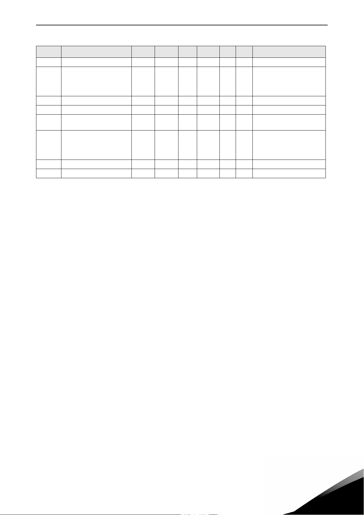
Local/Remote Control Application vacon • 36
Table 24. Protections, G2.7
Code Parameter Min Max Unit Default Cust ID Note
P2.7.16 Stall frequency limit 1,0 P2.1.2 Hz 25,0 712
0 = No response
P2.7.17 Underload protection 0 3 0 713
P2.7.18 Field weakening area load 10 150 % 50 714
P2.7.19 Zero frequency load 5,0 150,0 % 10,0 715
P2.7.20
P2.7.21
P2.7.22 Response to fieldbus fault 0 3 2 733 See P2.7.21
P2.7.23 Response to slot fault 0 3 734 See P2.7.21
Underload protection time
limit
Response to thermistor
fault
2 600 s 20 716
03 2 732
1 = Warning
2 = Fault, stop acc. to 2.4.7
3 = Fault, stop by coasting
0 = No response
1 = Warning
2 = Fault, stop acc. to 2.4.7
3 = Fault, stop by coasting
24-hour support +358 (0)201 212 575 • Email: vacon@vacon.com
3
Page 38

vacon • 37 Local/Remote Control Application
3.4.9 Autorestart parameters (Control keypad: Menu M2 -> G2.8)
Table 25. Autorestart parameters, G2.8
Code
P2.8.1 Wait time 0,10 10,00 s 0,50 717
P2.8.2 Trial time 0,00 60,00 s 30,00 718
P2.8.3 Start function 0 2 0 719
P2.8.4
P2.8.5
P2.8.6
P2.8.7
P2.8.8
P2.8.9
P2.8.10
Parameter
Number of tries after
undervoltage trip
Number of tries after
overvoltage trip
Number of tries after
overcurrent trip
Number of tries after
4mA reference trip
Number of tries after
motor temp fault trip
Number of tries after
external fault trip
Number of tries after
underload fault trip
Min Max Unit Default
0 10 0 720
0 10 0 721
0 3 0 722
0 10 0 723
0 10 0 726
0 10 0 725
010 0
Cust
738
ID Note
0 = Ramp
1 = Flying start
2 = According to P2.4.6
3.4.10 Keypad control (Control keypad: Menu M3)
The parameters for the selection of control place and direction on the keypad are listed below. See
the Keypad control menu in the product's User's Manual.
Table 26. Keypad control parameters, M3
Code Parameter Min Max Unit Default Cust ID Note
1 = I/O terminal
P3.1 Control place 1 3 1 125
P3.2 Keypad reference P2.1.1 P2.1.2 Hz
P3.3 Direction (on keypad) 0 1 0 123
R3.4 Stop button 0 1 1 114
2 = Keypad
3 = Fieldbus
0 = Forward
1 = Reverse
0 = Limited function of Stop button
1 = Stop button always enabled
3
Tel. +358 (0) 201 2121 • Fax +358 (0)201 212 205
Page 39

Local/Remote Control Application vacon • 38
3.4.11 System menu (Control keypad: Menu M6)
For parameters and functions related to the general use of the frequency converter, such as application and language selection, customised parameter sets or information about the hardware and
software, see the product's User's Manual.
3.4.12 Expander boards (Control keypad: Menu M7)
The M7 menu shows the expander and option boards attached to the control board and board-related information. For more information, see the product's User's Manual.
24-hour support +358 (0)201 212 575 • Email: vacon@vacon.com
3
Page 40

vacon • 39 Multi-step Speed Control Application
4. MULTI-STEP SPEED CONTROL APPLICATION
Software code: ASFIFF04
4.1 Introduction
Select the Multi-step Speed Control Application in menu M6 on page
The Multi-step Speed Control Application can be used in applications where fixed speeds are needed. Totally 15 + 2 different speeds can be programmed: one basic speed, 15 multi-step speeds and
one jogging speed. The speed steps are selected with digital signals DIN3, DIN4, DIN5 and DIN6. If
jogging speed is used, DIN3 can be programmed from fault reset to jogging speed select.
The basic speed reference can be either voltage or current signal via analogue input terminals (2/
3 or 4/5). The other one of the analogue inputs can be programmed for other purposes.
• All outputs are freely programmable.
Additional functions:
• Programmable Start/Stop and Reverse signal logic
• Reference scaling
• One frequency limit supervision
• Second ramps and S-shape ramp programming
• Programmable start and stop functions
• DC-brake at stop
• One prohibit frequency area
• Programmable U/f curve and switching frequency
• Autorestart
• Motor thermal and stall protection: Programmable action; off, warning, fault
The parameters of the Multi-Step Speed Control Application are explained in Chapter 8 of this manual. The explanations are arranged according to the individual ID number of the parameter.
S6.2
.
4
Tel. +358 (0) 201 2121 • Fax +358 (0)201 212 205
Page 41

Multi-step Speed Control Application vacon • 40
Reference potentiometer,
1…10 k
Basic reference
(optional)
Ju m p er b lo ck X 3 :
CM A and CMB grounding
CMB connected to GND
CM A connected to G ND
CMB isolated from GN D
CMA i solated from GN D
CMB and CMA
internally connected together,
isolated from GN D
= Factory default
Note: See jumper selections below.
Moreinformationintheproduct's
User's Manual.
7080.emf
RUN
4.2 Control I/O
Table 27. Multi-step speed control application default I/O configuration.
OPTA1
Terminal Signal Description
READY
mA
1 +10V
2 AI1+ Analogue input 1.
3 AI1- I/O Ground Ground for reference and controls
4 AI2+ Analogue input 2.
5 AI2-
6 +24V Control voltage output Voltage for switches, etc. max 0.1 A
7 GND I/O ground Ground for reference and controls
8 DIN1 Start forward
9DIN2Start reverse
10 DIN3 External fault input Programma-
11 CMA Common for DIN 1—DIN 3 Connect to GND or +24V
12 +24V Control voltage output Voltage for switches (see #6)
13 GND I/O ground Ground for reference and controls
14 DIN4 Preset speed select 1 sel 10sel 2
15 DIN5 Preset speed select 2 1
16 DIN6 Preset speed select 3 - - - - - -
17 CMB Common for DIN4—DIN6 Connect to GND or +24V
18 AO1+ Analogue Output 1:
19 AO1-
20 DO1 Digital output
OPTA2
21 RO1 Relay output 1
22 RO1
23 RO1
24 RO2 Relay output 2
25 RO2
26 RO2
Reference output Voltage for potentiometer, etc.
ref
Analogue input 1 frequency reference
Voltage range 0—10V DC
Analogue input 2 frequency reference
Current Range 0 – 20 mA
Default reference
Programmable (P2.1.11)
Contact closed = start forward
Programmable logic (P2.2.1 )
Contact closed = start reverse
min. = 5k
R
i
Contact open = no fault
ble (P2.2.2)
Contact closed = fault
sel 3 sel 4 (with DIN3)
0
0 0 I/O reference
0
0 0 Speed 1
0
1
0 0 Speed 2
1 1 1 1 Speed 15
Range 0—20 mA/R
Output frequency
Programmable (P2.3.2)
Open collector, I50mA, U48 VDC
READY
Programmable (P2.3.7)
Programmable
RUN
Programmable (P2.3.8)
Programmable
FAU LT
Programmable (P2.3.9)
, max. 500
L
24-hour support +358 (0)201 212 575 • Email: vacon@vacon.com
Figure 7.
4
Page 42

vacon • 41 Multi-step Speed Control Application
DIN4
DIN5
AI1
AI2
DIN1
DIN2
DIN3
>1
DIN6
DIN3
DIN3
3.2 Keypad reference
2.1.11 I/O Reference
2.1.12 Keypad Ctrl Reference
2.1.13 Fieldbus Ctrl Reference
2.1.15 Preset Speed 1
...2.1.29 Pre set Speed 15
3.1 Control place
Internal frequency
reference
Start forward
(programmable)
Start reverse (programmable)
Programmable
Start/Stop and
reverse logic
Start/Stop
Reverse
Internal Start/Stop
Internal reverse
Internal fault reset
Fault reset input
Reset button
Start/Stop buttons
Reference from fieldbus
Start/Stop from fieldbus
Direction from fieldbus
3.3 Keypad direction
Preset Speed 1
Preset Speed 2
Preset Speed 3
Preset Speed 4
2.1.14 Jogging speed
reference
(programmable)
7081.emf
4.3 Control signal logic in Multi-Step Speed Control Application
Figure 8. Control signal logic of the Multi-step Speed Application
4
Tel. +358 (0) 201 2121 • Fax +358 (0)201 212 205
Page 43

Multi-step Speed Control Application vacon • 42
4.4 Multi-step speed control application – Parameter lists
On the next pages you will find the lists of parameters within the respective parameter groups. The
parameter descriptions are given on pages 131 to 229.
Column explanations:
Code = Location indication on the keypad; Shows the operator the present parameter
number
Parameter = Name of parameter
Min = Minimum value of parameter
Max = Maximum value of parameter
Unit = Unit of parameter value; Given if available
Default = Value preset by factory
Cust = Customer’s own setting
ID = ID number of the parameter
= In parameter row: Use TTF method to program these parameters.
= On parameter code: Parameter value can only be changed after the frequency
converter has been stopped.
4.4.1 Monitoring values (Control keypad: menu M1)
The monitoring values are the actual values of parameters and signals as well as statuses and
measurements. Monitoring values cannot be edited.
See the product's User's Manual for more information.
Table 28. Monitoring values
Code Parameter Unit ID Description
V1.1 Output frequency Hz 1 Output frequency to motor
V1.2 Frequency reference Hz 25 Frequency reference to motor control
V1.3 Motor speed rpm 2 Motor speed in rpm
V1.4 Motor current A 3
V1.5 Motor torque % 4 Calculated shaft torque
V1.6 Motor power % 5 Motor shaft power
V1.7 Motor voltage V 6
V1.8 DC link voltage V 7
V1.9 Unit temperature C 8 Heatsink temperature
V1.10 Motor temperature % 9 Calculated motor temperature
V1.11 Analogue input 1 V/mA 13 AI1
V1.12 Analogue input 2 V/mA 14 AI2
V1.13 DIN1, DIN2, DIN3 15 Digital input statuses
V1.14 DIN4, DIN5, DIN6 16 Digital input statuses
V1.15 DO1, RO1, RO2 17 Digital and relay output statuses
V1.16
M1.17 Multimonitoring items Displays three selectable monitoring values
Analogue I
out
mA 26 AO1
24-hour support +358 (0)201 212 575 • Email: vacon@vacon.com
4
Page 44

vacon • 43 Multi-step Speed Control Application
4.4.2 Basic parameters (Control keypad: Menu M2 -> G2.1)
Table 29. Basic parameters G2.1
Code Parameter Min Max Unit Default Cust ID Note
P2.1.1 Min frequency 0,00 P2.1.2 Hz 0,00 101
NOTE: If f
motor synchronous
P2.1.2 Max frequency P2.1.1 320,00 Hz 50,00 102
P2.1.3 Acceleration time 1 0,1 3000,0 s 3,0 103
P2.1.4 Deceleration time 1 0,1 3000,0 s 3,0 104
P2.1.5 Current limit
P2.1.6
P2.1.7
P2.1.8
P2.1.9
P2.1.10 Motor cos 0,30 1,00 0,85 120
P2.1.11 I/O reference 0 3 1 117
P2.1.12
P2.1.13
P2.1.14 Jogging speed pref. 0,00 P2.1.2 Hz 0,00 124
P2.1.15 Preset speed 1 0,00 P2.1.2 Hz 5,00 105 Multi-step speed 1
P2.1.16 Preset speed 2 0,00 P2.1.2 Hz 10,00 106 Multi-step speed 2
P2.1.17 Preset speed 3 0,00 P2.1.2 Hz 12,50 126 Multi-step speed 3
P2.1.18 Preset speed 4 0,00 P2.1.2 Hz 15,00 127 Multi-step speed 4
P2.1.19 Preset speed 5 0,00 P2.1.2 Hz 17,50 128 Multi-step speed 5
P2.1.20 Preset speed 6 0,00 P2.1.2 Hz 20,00 129 Multi-step speed 6
P2.1.21 Preset speed 7 0,00 P2.1.2 Hz 22,50 130 Multi-step speed 7
P2.1.22 Preset speed 8 0,00 P2.1.2 Hz 25,00 133 Multi-step speed 8
P2.1.23 Preset speed 9 0,00 P2.1.2 Hz 27,50 134 Multi-step speed 9
P2.1.24 Preset speed 10 0,00 P2.1.2 Hz 30,00 135 Multi-step speed 10
P2.1.25 Preset speed 11 0,00 P2.1.2 Hz 32,50 136 Multi-step speed 11
P2.1.26 Preset speed 12 0,00 P2.1.2 Hz 35,00 137 Multi-step speed 12
P2.1.27 Preset speed 13 0,00 P2.1.2 Hz 40,00 138 Multi-step speed 13
P2.1.28 Preset speed 14 0,00 P2.1.2 Hz 45,00 139 Multi-step speed 14
P2.1.29 Preset speed 15 0,00 P2.1.2 Hz 50,00 140 Multi-step speed 15
Nominal voltage of
the motor
Nominal frequency of
the motor
Nominal speed of the
motor
Nominal current of
the motor
Keypad control refer-
ence
Fieldbus control ref-
erence
0,1 x I
180 690 V
8,00 320,00 Hz 50,00 111
24 20 000 rpm 1440 112
0,1 x I
2 x I
H
H
0 3 2 121
0 3 3 122
2 x I
H
H
A
A
I
L
NX2: 230V
NX5: 400V
NX6: 690V
I
H
speed, check suitability
for motor and drive system
107
110
Check the rating plate of
the motor
The default applies for a
4-pole motor and a nominal size frequency converter.
Check the rating plate of
113
the motor.
Check the rating plate of
the motor
0 = AI1
1 = AI2
2 = Keypad
3 = Fieldbus
0 = AI1
1 = AI2
2 = Keypad
3 = Fieldbus
0 = AI1
1 = AI2
2 = Keypad
3 = Fieldbus
> than the
max
4
Tel. +358 (0) 201 2121 • Fax +358 (0)201 212 205
Page 45

Multi-step Speed Control Application vacon • 44
4.4.3 Input signals (Control keypad: Menu M2 -> G2.2)
Table 30. Input signals, G2.2
Code Parameter Min Max Unit Default Cust ID Note
DIN1 DIN2
0
P2.2.1 Start/Stop logic 0 6 0
P2.2.2 DIN3 function 0 13 1 301
P2.2.3 AI1 signal selection 0.1 E.10 A.1 377
P2.2.4 AI1 signal range 0 2 0 320
P2.2.5
P2.2.6
P2.2.7 AI1 signal inversion 0 1 0 323
P2.2.8 AI1 signal filter time 0,00 10,00 s 0,10 324
P2.2.9 AI2 signal selection 0.1 E.10 A.2 388
P2.2.10 AI2 signal range 0 2 1
P2.2.11
P2.2.12
P2.2.13 AI2 signal inversion 0 1 0 328
P2.2.14 AI2 signal filter time 0,00 10,00 s 0,10 329
P2.2.15
AI1 custom setting
minimum
AI1 custom setting
maximum
AI2 custom setting
minimum
AI2 custom setting
maximum
Reference scaling
minimum value
-160,00 160,00
-160,00 160,00
-160,00 160,00 % 0,00 326 Analogue input 2 scale minimum
-160,00 160,00 % 100,00 327 Analogue input 2 scale maximum
0,00 320,00 Hz 0,00 303
%
0,00 321 Analogue input 1 scale minimum
%
100,0 322 Analogue input 1 scale maximum
300
325
Start fwd
1
Start/Stop
2
Start/Stop
3
Start pulse
4
Start fwd*
5
Start*/Stop
6
Start*/Stop
0 = Not used
1 = Ext. fault, closing cont.
2 = Ext. fault, opening cont.
3 = Run enable
4 = Acc./Dec. time select.
5 = Force cp. to IO
6 = Force cp. to keypad
7 = Force cp. to fieldbus
8 = Rvs (if P2.2.1 2,3 or 6)
9 = Jogging speed
10 = Fault reset
11 = Acc./Dec. operation prohibit
12 = DC Braking command
13 = Preset speed
TTF programming method used.
See page 72.
0 = 0–10 V (0-20 mA**)
1 = 2-10 V (4-20 mA**)
2 = Custom setting range**
Analogue input 1 reference inversion yes/no
Analogue input 1 reference filter
time, constant
TTF programming method used.
See page 72.
0 = 0-20 mA (0–10 V**)
1 = 4-20 mA (2-10 V**)
2 = Custom setting range
Analogue input 2 reference inversion yes/no
Analogue input 2 reference filter
time, constant
Selects the frequency that corresponds to the min. reference signal
Start rvs
Rvs/Fwd
Run enable
Stop pulse
Start rvs*
Reverse
Run enable
24-hour support +358 (0)201 212 575 • Email: vacon@vacon.com
4
Page 46

vacon • 45 Multi-step Speed Control Application
Table 30. Input signals, G2.2
Code Parameter Min Max Unit Default Cust ID Note
Selects the frequency that corre-
P2.2.16
P2.2.17
P2.2.18
Reference scaling
maximum value 0,00 320,00 Hz 0,00 304
Free analogue input,
signal selection
Free analogue input,
function
02 0 361
04 0 362
sponds to the max. reference signal
0,00 = No scaling
>0 = scaled max. value
0 = Not used
1 = AI1
2 = AI2
0 = No function
1 = Reduces current limit (P2.1.5)
2 = Reduces DC braking current,
P2.4.8
3 = Reduces accel. and decel.
times
4 = Reduces torque supervision
limit P2.3.15)
CP=control place
cc=closing contact
oc=opening contact
* = Rising edge required to start
** = Remember to place jumpers of block X2 accordingly. See the product's User's Manual
4
Tel. +358 (0) 201 2121 • Fax +358 (0)201 212 205
Page 47

Multi-step Speed Control Application vacon • 46
4.4.4 Output signals (Control keypad: Menu M2 -> G2.3)
Table 31. Output signals, G2.3
Code Parameter Min Max Unit Default Cust ID Note
P2.3.1 AO1 signal selection 0.1 E.10 A.1 464
P2.3.2 Analogue output function 0 8 1 307
P2.3.3 Analogue output filter time 0,00 10,00 s 1,00 308 0 = No filtering
P2.3.4 Analogue output inversion
P2.3.5 Analogue output minimum
P2.3.6 Analogue output scale 10 1000 % 100 311
P2.3.7 Digital output 1 function 0 22 1 312
P2.3.8 Relay output 1 function 0 22 2 313 As parameter 2.3.7
P2.3.9 Relay output 2 function 0 22 3 314 As parameter 2.3.7
P2.3.10
P2.3.11
P2.3.12
P2.3.13
Output frequency limit 1
supervision
Output frequency limit 1;
Supervision value
Output frequency limit 2
supervision
Output frequency limit 2;
Supervision value
0
0
0 2 0 315
0,00 320,00 Hz 0,00 316
0 2 0 346
0,00 320,00 Hz 0,00 347
1 0 309
1 0 310
TTF programming method
used. See page 72.
0 = Not used (20 mA / 10 V)
1 = Output freq. (0—f
2 = Freq. reference (0—f
3 = Motor speed (0—Motor
nominal speed)
4 = Motor current (0—I
5 = Motor torque (0—T
6 = Motor power (0—P
7 = Motor voltage (0-U
8 = DC-link volt (0—1000V)
0 = Not inverted
1 = Inverted
0 = 0 mA (0 V)
1 = 4 mA (2 V)
0 = Not used
1 = Ready
2 = Run
3 = Fault
4 = Fault inverted
5 = FC overheat warning
6 = Ext. fault or warning
7 = Ref. fault or warning
8 = Warning
9 = Reversed
10 = Jogging spd selected
11 = At speed
12 = Mot. regulator active
13 = OP freq.limit superv. 1
14 = OP freq.limit superv. 2
15 = Torque limit superv.
16 = Ref. limit superv.
17 = Ext. brake control
18 = Control place: IO
19 = FC temp. limit superv.
20 = Unrequested rotation
direction
21 = Ext. brake control inverted
22 = Thermistor fault/warn.
0 = No limit
1 = Low limit supervision
2 = High limit supervision
0 = No limit
1 = Low limit supervision
2 = High limit supervision
max
nMotor
nMotor
nMotor
nMotor
)
max
)
)
)
)
)
24-hour support +358 (0)201 212 575 • Email: vacon@vacon.com
4
Page 48

vacon • 47 Multi-step Speed Control Application
Table 31. Output signals, G2.3
Code Parameter Min Max Unit Default Cust ID Note
P2.3.14
P2.3.15
P2.3.16
P2.3.17
P2.3.18 External brake Off-delay 0,0 100,0 s 0,5 352
P2.3.19 External brake On-delay 0,0 100,0 s 1,5 353
P2.3.20
P2.3.21
P2.3.22
P2.3.23 Analogue output 2 function 0 8 4 472 As parameter 2.3.2
P2.3.24 Analogue output 2 filter time 0,00 10,00 s 1,00 473 0 = No filtering
P2.3.25 Analogue output 2 inversion 0 1 0 474
P2.3.26 Analogue output 2 minimum 0 1 0 475
P2.3.27 Analogue output 2 scaling 10 1000 % 100 476
Torque limit supervision
function
Torque limit supervision
value
Reference limit supervision
function
Reference limit supervision
value
Frequency converter temperature limit supervision
Frequency converter tem-
perature limit value
Analogue output 2 signal
selection
0 2 0 348
-300,0 300,0 % 100,0 349
0 2 0 350
0,0 100,0 % 0,0 351
0 2 0 354
-10 100 C 40 355
0.1 E.10 0.1 471
0 = No
1 = Low limit
2 = High limit
0 = No
1 = Low limit
2 = High limit
0 = No
1 = Low limit
2 = High limit
TTF programming method
used. See page 72 .
0 = Not inverted
1 = Inverted
0 = 0 mA (0 V)
1 = 4 mA (2 V)
4
Tel. +358 (0) 201 2121 • Fax +358 (0)201 212 205
Page 49

Multi-step Speed Control Application vacon • 48
4.4.5 Drive control parameters (Control keypad: Menu M2 -> G2.4)
Table 32. Drive control parameters, G2.4
Code Parameter Min Max Unit Default Cust ID Note
P2.4.1 Ramp 1 shape 0,0 10,0 s 0,1 500
P2.4.2 Ramp 2 shape 0,0 10,0 s 0,0 501
P2.4.3 Acceleration time 2 0,1 3000,0 s 10,0 502
P2.4.4 Deceleration time 2 0,1 3000,0 s 10,0 503
P2.4.5 Brake chopper 0 4 0 504
P2.4.6 Start function 0 2 0 505
P2.4.7 Stop function 0 3 0 506
P2.4.8 DC braking current 0,00
P2.4.9
P2.4.10
P2.4.11
P2.4.12 Flux brake 0 1 0 520
P2.4.13 Flux braking current 0,00
DC braking time
at stop
Frequency to start DC
braking during
ramp stop
DC braking time
at start
0,00 600,00 s 0,00 508 0 = DC brake is off at stop
0,10 10,00 Hz 1,50 515
0,00 600,00 s 0,00 516 0 = DC brake is off at start
I
L
I
L
0,7 x I
A
A
H
I
H
507
519
0 = Linear
>0 = S-curve ramp time
0 = Linear
>0 = S-curve ramp time
0 = Disabled
1 = Used when running
2 = External brake chopper
3 = Used when stopped/
running
4 = Used when running (no
testing)
0 = Ramp
1 = Flying start
2 = Conditional flying start
0 = Coasting
1 = Ramp
2 = Ramp+Run enable coast
3 = Coast+Run enable ramp
0 = Off
1 = On
24-hour support +358 (0)201 212 575 • Email: vacon@vacon.com
4
Page 50

vacon • 49 Multi-step Speed Control Application
4.4.6 Prohibit frequency parameters (Control keypad: Menu M2 -> G2.5)
Table 33. Prohibit frequency parameters, G2.5
Code Parameter Min Max Unit Default Cust ID Note
P2.5.1
P2.5.2
P2.5.3
P2.5.4
P2.5.5
P2.5.6
P2.5.7
Prohibit frequency
range 1 low limit
Prohibit frequency
range 1 high limit
Prohibit frequency
range 2 low limit
Prohibit frequency
range 2 high limit
Prohibit frequency
range 3 low limit
Prohibit frequency
range 3 high limit
Prohibit acc./dec.
ramp
0,00 320,00 Hz 0,00 509
0,00 320,00 Hz 0,00 510
0,00 320,00 Hz 0,00 511
0,00 320,00 Hz 0,00 512 0 = Prohibit range 2 is off
0,00 320,00 Hz 0,00 513
0,00 320,00 Hz 0,00 514 0 = Prohibit range 3 is off
0,1 10,0 x 1,0 518
0 = Prohibit range 1 is off
4.4.7 Motor control parameters (Control keypad: Menu M2 G2.6)
Table 34. Motor control parameters, G2.6
Code Parameter Min Max Unit Default Cust ID Note
0 = Frequency control
1 = Speed control
P2.6.1 Motor control mode 0 1/3 0 600
P2.6.2 U/f optimisation 0 1 0 109
P2.6.3 U/f ratio selection 0 3 0 108
P2.6.4 Field weakening point 8,00 320,00 Hz 50,00 602
P2.6.5
P2.6.6
P2.6.7
P2.6.8
P2.6.9 Switching frequency 1,0 Varies kHz Varies 601
P2.6.10 Overvoltage controller 0 2 1 607
P2.6.11
P2.6.12 Load drooping 0,00 100,00 % 0,00 620
P2.6.13 Identification 0 1/2 0 631
Voltage at field weak-
ening point
U/f curve midpoint fre-
quency
U/f curve midpoint
voltage
Output voltage at zero
frequency
Undervoltage control-
ler
10,00 200,00 % 100,00 603
0,00 P2.6.4 Hz 50,00 604
0,00 100,00 % 100,00 605
0,00 40,00 % Varies 606
0 1 1 608
Additionally for NXP:
2 = Not used
3 = Closed loop speed ctrl
0 = Not used
1 = Automatic torque boost
0 = Linear
1 = Squared
2 = Programmable
3 = Linear with flux optim.
n% x U
nmot
n% x U
nmot
Parameter max. value =
P2.6.5
n% x U
nmot
See Table 121 for exact values
0 = Not used
1 = Used (no ramping)
2 = Used (ramping
0 = Not used
1 = Used
0 = No action
1 = Identification w/o run
2 = Identification with run
4
Tel. +358 (0) 201 2121 • Fax +358 (0)201 212 205
Page 51

Multi-step Speed Control Application vacon • 50
Table 34. Motor control parameters, G2.6
Code Parameter Min Max Unit Default Cust ID Note
Closed Loop parameter group 2.6.14
P2.6.14.1 Magnetizing current 0,00
P2.6.14.2 Speed control P gain 1 1000 30 613
P2.6.14.3 Speed control I time 0,0 3200,0 ms 30,0 614
P2.6.14.5
P2.6.14.6 Slip adjust 0 500 % 100 619
P2.6.14.7
P2.6.14.8
P2.6.14.9 0-speed time at start 0 32000 ms 100 615
P2.6.14.10 0-speed time at stop 0 32000 ms 100 616
P2.6.14.11 Start-up torque 0 3 0 621
P2.6.14.12 Start-up torque FWD –300,0 300,0 % 0,0 633
P2.6.14.13 Start-up torque REV –300,0 300,0 % 0,0 634
P2.6.14.15 Encoder filter time 0,0 100,0 ms 0,0 618
P2.6.14.17
Acceleration compen-
sation
Magnetizing current at
start
Magnetizing time at
start
Current control
P gain
0,00 300,00 s 0,00 626
0,00
0 60000 ms 0 628
0,00 100,00 % 617
2 x I
I
A 0,00 612
H
L
A 0,00 627
0 = Not used
1 = Torque memory
2 = Torque reference
3 = Start-up torque fwd/rev
Identification parameter group 2.6.15
P2.6.15.1 Speed step -50,0 50,0 0,0 0,0 1252 NCDrive speed tuning
24-hour support +358 (0)201 212 575 • Email: vacon@vacon.com
4
Page 52

vacon • 51 Multi-step Speed Control Application
4.4.8 Protections (Control keypad: Menu M2 -> G2.7)
Table 35. Protections, G2.7
Code Parameter Min Max Unit Default Cust ID Note
0 = No response
1 = Warning
P2.7.1
P2.7.2
P2.7.3
P2.7.4
P2.7.5
P2.7.6
P2.7.7
P2.7.8
P2.7.9
P2.7.10
P2.7.11
P2.7.12 Motor duty cycle 0 150 % 100 708
P2.7.13 Stall protection 0 3 0 709
P2.7.14 Stall current 0,00
P2.7.15 Stall time limit 1,00 120,00 s 15,00 711
P2.7.16
P2.7.17
P2.7.18
P2.7.19 Zero frequency load 5,0 150,0 % 10,0 715
P2.7.20
P2.7.21
P2.7.22
P2.7.23
Response to 4mA
reference fault
4mA refe rence fault
frequency
Response to
external fault
Input phase
supervision
Response to under-
voltage fault
Output phase
supervision
Earth fault
protection
Thermal protection
of the motor
Motor ambient
temperature factor
Motor cooling fac-
tor at zero speed
Motor thermal time
constant
Stall frequency
limit
Underload protec-
tion
Field weakening
area load
Underload protec-
tion time limit
Response to
thermistor fault
Response to field-
bus fault
Response to slot
fault
05 0 700
0,00 P2.1.2 Hz 0,00 728
03 2 701
03 0 730
01 0 727
03 2 702
03 2 703
03 2 704
–100,0 100,0 % 0,0 705
0,0 150,0 % 40,0 706
1 200 min Varies 707
2 x I
1,0 P2.1.2 Hz 25,0 712
03 0 713
10 150 % 50 714
2 600 s 20 716
03 2 732
0 3 2 733 See P2.7.21
0 3 2 734 See P2.7.21
A
H
I
H
2 = Warning+Previous Freq.
3 = Wrng+PresetFreq 2.7.2
4 = Fault,stop acc. to 2.4.7
5 = Fault,stop by coasting
0 = No response
1 = Warning
2 = Fault,stop acc. to 2.4.7
3 = Fault,stop by coasting
0 = Fault stored in history
1 = Fault not stored
0 = No response
1 = Warning
2 = Fault,stop acc. to 2.4.7
3 = Fault,stop by coasting
0 = No response
1 = Warning
2 = Fault,stop acc. to 2.4.7
3 = Fault,stop by coasting
710
0 = No response
1 = Warning
2 = Fault,stop acc. to 2.4.7
3 = Fault,stop by coasting
0 = No response
1 = Warning
2 = Fault,stop acc. to 2.4.7
3 = Fault,stop by coasting
4
Tel. +358 (0) 201 2121 • Fax +358 (0)201 212 205
Page 53

Multi-step Speed Control Application vacon • 52
4.4.9 Autorestart parameters (Control keypad: Menu M2 -> G2.8)
Table 36. Autorestart parameters, G2.8
Code
P2.8.1
P2.8.2 Trial time 0,00 60,00 s 30,00 718
P2.8.3 Start function 0 2 0 719
P2.8.4
P2.8.5
P2.8.6
P2.8.7
P2.8.8
P2.8.9
P2.8.10
Parameter
Wait time 0,10 10,00 s 0,50 717
Number of tries after
undervoltage trip
Number of tries after
overvoltage trip
Number of tries after
overcurrent trip
Number of tries after
4mA reference trip
Number of tries after
motor temp fault trip
Number of tries after
external fault trip
Number of tries after
underload fault trip
Min Max Unit Default Cust ID Note
0 10 0 720
0 10 0 721
0 3 0 722
0 10 0 723
0 10 0 726
0 10 0 725
0 10 0 738
0 = Ramp
1 = Flying start
2 = According to P2.4.6
4.4.10 Keypad control (Control keypad: Menu M3)
The parameters for the selection of control place and direction on the keypad are listed below. See
the Keypad control menu in the product's user's manual.
Table 37. Keypad control parameters, M3
Code Parameter Min Max Unit Default
P3.1 Control place 1 3 1 125
P3.2 Keypad reference P2.1.1 P2.1.2 Hz
P3.3 Direction (on keypad) 0 1 0 123
R3.4 Stop button 0 1 1 114
Cust
ID Note
1 = I/O terminal
2 = Keypad
3 = Fieldbus
0 = Forward
1 = Reverse
0 = Limited function of Stop button
1 = Stop button always enabled
4.4.11 System menu (Control keypad: M6)
For parameters and functions related to the general use of the frequency converter, such as application and language selection, customised parameter sets or information about the hardware and
software, see the product's user's manual.
4.4.12 Expander boards (Control keypad: Menu M7)
The M7 menu shows the expander and option boards attached to the control board and board-related information. For more information, see the product's user's manual.
24-hour support +358 (0)201 212 575 • Email: vacon@vacon.com
4
Page 54

vacon • 53 PID Control Application
5. PID CONTROL APPLICATION
Software code: ASFIFF05
5.1 Introduction
Select the PID Control Application in menu M6 on page
In the PID Control Application, there are two I/O terminal control places; place A is the PID controller and source B is the direct frequency reference. The control place A or B is selected with digital
input DIN6.
The PID controller reference can be selected from the analogue inputs, fieldbus, motorised potentiometer, enabling the PID Reference 2 or applying the control keypad reference. The PID controller
actual value can be selected from the analogue inputs, fieldbus, the actual values of the motor or
through the mathematical functions of these.
The direct frequency reference can be used for the control without the PID controller and selected
from the analogue inputs, fieldbus, motor potentiometer or keypad.
The PID Application is typically used to control level measuring or pumps and fans. In these applications, the PID Application provides a smooth control and an integrated measuring and controlling
package where no additional components are needed.
• Digital inputs DIN2, DIN3, DIN5 and all the outputs are freely programmable.
Additional functions:
• Analogue input signal range selection
• Two frequency limit supervisions
• Torque limit supervision
• Reference limit supervision
• Second ramps and S-shape ramp programming
• Programmable start and stop functions
• DC-brake at start and stop
• Three prohibit frequency areas
• Programmable U/f curve and switching frequency
• Autorestart
• Motor thermal and stall protection: fully programmable; off, warning, fault
• Motor underload protection
• Input and output phase supervision
• Sum point frequency addition to PID output
• The PID controller can additionally be used from control places I/O B, keypad and fieldbus
• Easy ChangeOver function
• Sleep function
S6.2
.
5
The parameters of the PID Control Application are explained in Chapter 8 of this manual. The explanations are arranged according to the individual ID number of the parameter.
Tel. +358 (0) 201 2121 • Fax +358 (0)201 212 205
Page 55

PID Control Application vacon • 54
Reference potentiometer,
1…10 k
Ju m p er b lo ck X 3 :
CM A and CMB grounding
CMB connected to GND
CM A connected to G ND
CMB isolated from GN D
CMA i solated from GN D
CMB and CMA
internally connected together,
isolated from GN D
= Factory default
Note: See jumper selections below.
Moreinformationintheproduct's
user's manual.
7082.emf
RUN
5.2 Control I/O
2 wire Transmitter
Actual
value
(0) 4...20
mA
READY
mA
Table 38. PID application default I/O configuration (with 2-wire transmitter).
OPTA1
Ter mina l Signal Description
1 +10V
2 AI1+ Analogue input 1
Reference output Description
ref
Voltage for potentiometer, etc.
Voltage range 0—10V DC
Programmable (P2.1.11)
3 AI1- I/O Ground Analogue input 1 PID reference
4 AI2+ Analogue input 2
5 AI2- Analogue input 2 PID actual value 1
Current range 0—20mA
Ground for reference and controls
Programmable (P2.2.9)
6 +24V Control voltage output
7 GND I/O ground Voltage for switches, etc. max 0.1 A
8 DIN1 Place A: Start forward
R
min. = 5k
i
9 DIN2 External fault input
Programmable (P2.2.1)
10 DIN3 Fault reset
Programmable (P2.2.2)
Ground for reference and controls
Start signal for control place A
PID Controller.
Contact closed = fault
Contact open = no fault
11 CMA Common for DIN 1—DIN 3 Contact closed = fault reset
12 +24V Control voltage output Connect to GND or +24V
13 GND I/O ground Voltage for switches (see #6)
14 DIN4 Place B: Start forward
R
min. = 5k
i
15 DIN5 Jogging speed selection
Programmable (P2.2.3)
Ground for reference and controls
Start signal for control place B
Frequency reference (P2.2.5.)
16 DIN6 Control place A/B selection Contact closed = Jogging speed active
17 CMB Common for DIN4—DIN6 Contact open = Control place A is
active
Contact closed = Control place B is
active
18 AO1+ Analogue output 1
19 AO1- Range 0—20 mA/R
Output frequency
Programmable (P2.3.2)
20 DO1 Digital output
Connect to GND or +24V
, max. 500
L
Open collector, I50mA, U48 VDC
READY
Programmable (P2.3.7)
OPTA2
21 RO1 Relay output 1
22 RO1
23 RO1
Programmable (P2.3.8)
RUN
24 RO2 Relay output 2
25 RO2
26 RO2
Programmable (P2.3.9)
FAU LT
24-hour support +358 (0)201 212 575 • Email: vacon@vacon.com
Figure 9.
5
Page 56

vacon • 55 PID Control Application
DI N2
DI N5
DI N3
>1
DI N2
DI N3
DI N5
DI N6
DI N2
DI N3
AI1
AI2
0
1
2
3
4
0
1
2
3
4
5
+A
A
B
0
1
2
3
4
5
0
1
2
3
4
5
K
0
1
2
3
4
5
F
PID
+
DIN1
DIN4
A
B
A
B
A/B
Internal revers e
Internal fault reset
Fault reset input (programmable)
3. 3 Key pad dire ction
Internal Start/Stop
Reference from fieldbus
Start/Stop fro m fieldbus
Direct ion from fi eldbus
External fault (programmable)
Jogging speed (programmable)
Place A/B selection
2. 2.4 PID main re fer ence
Motor
potentiomet er
Up
Do wn
2.1. 11 PID r efe rence
I/O revers e
R3.4 PID keypad refer.
R3.2 Keypad reference
Actual values
sel ect ion, par.
2.2.9 & 2.2.10
Actua l value
select ion par . 2.2 .8
Act 1
Act 2
R3.5 PID keypad ref. 2
Enabl e PID k eypad re f. 2 ( DI N5=13)
Start; Place A
Start ; Place B
Start/Stop
Star t/Sto p b utton s
Inter nal
frequency ref.
2. 1.1 9 Jog ging s peed r ef.
Key pad
Fieldbus
Reset button
3.1 Control place
2.2.7 Fieldbus Ctrl Reference
2.2.6 Keypad Crtl Reference
2.2.5 I/O B Reference
7083.emf
5.3 Control signal logic in PID Control Application
Figure 10.Control signal logic of the PID Control Application
5
Tel. +358 (0) 201 2121 • Fax +358 (0)201 212 205
Page 57

PID Control Application vacon • 56
5.4 PID Application – Parameter lists
On the next pages you will find the lists of parameters within the respective parameter groups. The
parameter descriptions are given on pages 131 to 229.
Column explanations:
Code = Location indication on the keypad; Shows the operator the present param. number
Parameter = Name of parameter
Min = Minimum value of parameter
Max = Maximum value of parameter
Unit = Unit of parameter value; Given if available
Default = Value preset by factory
Cust = Customer’s own setting
ID = ID number of the parameter
= In parameter row: Use TTF method to program these parameters.
= On code: Parameter value can only be changed after the FC has been stopped.
5.4.1 Monitoring values (Control keypad: menu M1)
The monitoring values are the actual values of parameters and signals as well as statuses and
measurements. Monitoring values cannot be edited.
See the product's user's manual for more information. Note that the monitoring values V1.19 to
V1.22 are available with the PID control application only.
Table 39. Monitoring values
Code Parameter Unit ID Description
V1.1 Output frequency Hz 1 Output frequency to motor
V1.2 Frequency reference Hz 25 Frequency reference to motor control
V1.3 Motor speed rpm 2 Motor speed in rpm
V1.4 Motor current A 3
V1.5 Motor torque % 4 Calculated shaft torque
V1.6 Motor power % 5 Motor shaft power
V1.7 Motor voltage V 6
V1.8 DC link voltage V 7
V1.9 Unit temperature
V1.10 Motor temperature % 9 Calculated motor temperature
V1.11 Analogue input 1 V/mA 13 AI1
V1.12 Analogue input 2 V/mA 14 AI2
V1.13 Analogue input 3 27 AI3
V1.14 Analogue input 4 28 AI4
V1.15 DIN1, DIN2, DIN3 15 Digital input statuses
V1.16 DIN4, DIN5, DIN6 16 Digital input statuses
V1.17 DO1, RO1, RO2 17 Digital and relay output statuses
V1.18
V1.19 PID Reference % 20 In % of the max. frequency
V1.20 PID Actual value % 21 In % of the max. actual value
V1.21 PID Error value % 22 In % of the max. error value
V1.22 PID Output % 23 In % of the max. output value
V1.23 Special display for actual value 29 See parameters 2.2.46 to 2.2.49
V1.24 PT-100 Temperature Cº 42 Highest temperature of used inputs
G1.25 Monitoring items Displays three selectable monitoring values
Analogue I
out
C
mA 26 AO1
8 Heatsink temperature
24-hour support +358 (0)201 212 575 • Email: vacon@vacon.com
5
Page 58

vacon • 57 PID Control Application
5.4.2 Basic parameters (Control keypad: Menu M2 -> G2.1)
Table 40. Basic parameters G2.1
Code Parameter Min Max Unit Default Cust ID Note
P2.1.1 Min frequency 0,00 P2.1.2 Hz 0,00 101
P2.1.2 Max frequency P2.1.1 320,00 Hz 50,00 102
P2.1.3 Acceleration time 1 0,1 3000,0 s 1,0 103
P2.1.4 Deceleration time 1 0,1 3000,0 s 1,0 104
P2.1.5 Current limit
P2.1.6
P2.1.7
P2.1.8
P2.1.9
P2.1.10 Motor cos 0,30 1,00 0,85 120
P2.1.11
P2.1.12 PID controller gain 0,0 1000,0 % 100,0 118
P2.1.13 PID controller I-time 0,00 320,00 s 1,00 119
P2.1.14 PID controller D-time 0,00 100,00 s 0,00 132
P2.1.15 Sleep frequency 0,00 P 2.1.2 Hz 10,00 1016
P2.1.16 Sleep delay 0 3600 s 30 1017
P2.1.17 Wake up level 0,00 100,00 % 25,00 1018
P2.1.18 Wake up function 0 1 0 1019
P2.1.19
Nominal voltage of the
motor
Nominal frequency of
the motor
Nominal speed of the
motor
Nominal current of the
motor
PID controller reference
signal (Place A)
Jogging speed
reference
0,1 x I
180 690 V
8,00 320,00 Hz 50,00 111
24 20 000 rpm 1440 112
0,1 x I
0,00 P2.1.2 Hz 10,00 124
2 x I
H
2 x I
H
04 0 332
A
H
A
H
I
L
NX2:
230V
NX5:
400V
NX6:
690V
I
H
107
110
113
NOTE: If f
synchronous speed, check suit-
ability for motor and drive system
NOTE: If PID-controller is used,
Acceleration time 2 (P2.4.3) is
automati-cally applied
NOTE: If PID-controller is used,
Deceleration time 2 (P2.4.4) is
automati-cally applied
Check the rating plate of the
motor
The default applies for a 4-pole
motor and a nominal size frequency converter.
Check the rating plate of the
motor.
Check the rating plate of the
motor
0 = AI1
1 = AI2
2 = PID ref from Keypad control
page, P3.4
3 = PID ref from fieldbus (Pro
cessDataIN 1)
4 = Motor potentiometer
0 = Wake-up at fall below wake
up level (2.1.17)
1 = Wake-up at exceeded wake
up level (2.1.17)
> than the motor
max
5
Tel. +358 (0) 201 2121 • Fax +358 (0)201 212 205
Page 59

PID Control Application vacon • 58
5.4.3 Input signals (Control keypad: Menu M2 -> G2.2)
Table 41. Input signals, G2.2
Code Parameter Min Max Unit Default Cust ID Note
0 = Not used
1 = External fault cc
2 = External fault oc
3 = Run enable
4 = Acc/Dec time selection
5 = CP: I/O terminal (ID125)
P2.2.1 DIN2 function 0 13 1 319
P2.2.2 DIN3 function 0 13 10 301
P2.2.3 DIN5 function 0 13 9 330
P2.2.4
P2.2.5
P2.2.6
P2.2.7
P2.2.8 Actual value selection 0 7 0 333
PID sum point refer-
ence
I/O B reference selec-
tion
Keypad control refer-
ence selection
Fieldbus control refer-
ence selection
0 7 0 376
0 7 1 343
0 7 4 121 As in P2.2.5
0 7 5 122 As in P2.2.5
6 = CP: Keypad (ID125)
7 = CP: Fieldbus (ID125)
8 = Forward/Reverse
9 = Jogging frequency (cc)
10 = Fault reset (cc)
11 = Acc/Dec prohibit (cc)
12 = DC braking command
13 = Motor pot. UP (cc)
See above except:
13 = Motor pot. DOWN (cc)
See above except:
13 = Enable PID reference 2
0 = Direct PID output value
1 = AI1+PID output
2 = AI2+PID output
3 = AI3+PID output
4 = AI4+PID output
5 = PID keypad+PID output
6 = Fieldbus+PID output
(ProcessDataIN3)
7 = Mot.pot.+PID output
0 = AI1
1 = AI2
2 = AI3
3 = AI4
4 = Keypad reference
5 = Fieldbus reference
(FBSpeedReference)
6 = Motor potentiometer
7 = PID controller
0 = Actual value 1
1 = Actual 1 + Actual 2
2 = Actual 1 – Actual 2
3 = Actual 1 * Actual 2
4 = Min(Actual 1, Actual 2)
5 = Max(Actual 1, Actual 2)
6 = Mean(Actual1, Actual2)
7 = Sqrt (Act1) + Sqrt (Act2)
24-hour support +358 (0)201 212 575 • Email: vacon@vacon.com
5
Page 60

vacon • 59 PID Control Application
Table 41. Input signals, G2.2
Code Parameter Min Max Unit Default Cust ID Note
0 = Not used
1 = AI1 signal (c-board)
2 = AI2 signal (c-board)
3 = AI3
P2.2.9
P2.2.10 Actual value 2 input 0 9 0 335
P2.2.11
P2.2.12
P2.2.13
P2.2.14
P2.2.15 AI1 signal selection 0.1 E.10 A.1 377
P2.2.16 AI1 signal range 0 2 0 320
P2.2.17
P2.2.18
P2.2.19 AI1 inversion 0 1 0 323
P2.2.20 AI1 filter time 0,00 10,00 s 0,10 324 0 = No filtering
P2.2.21 AI2 signal selection 0.1 E.10 A.2 388
P2.2.22 AI2 signal range 0 2 1 325
P2.2.23
P2.2.24
P2.2.25 AI2 inversion 0 0 0 328
P2.2.26 AI2 filter time
Actual value 1 selec-
tion
Actual value 1 mini-
mum scale
Actual value 1 maxi-
mum scale
Actual value 2 mini-
mum scale
Actual value 2 maxi-
mum scale
AI1 custom minimum
setting
AI1 custom maximum
setting
AI2 custom minimum
setting
AI2 custom maximum
setting
0 10 2 334
–1600,0 1600,0 % 0,0 336 0 = No minimum scaling
–1600,0 1600,0 % 100,0 337 100 = No maximum scaling
–1600,0 1600,0 % 0 338 0 = No minimum scaling
–1600,0
-160,00 160,00
-160,00 160,00 % 100,0 322
-160,00 160,00
-160,00
0,00 10,00
1600,0 % 100,0 339
% 0,00 321
% 0,00 326
160,00 %
s 0,10 329 0 = No filtering
0,00
4 = AI4
5 = Fieldbus
6 = Motor torque
7 = Motor speed
8 = Motor current
9 = Motor power
10 = Encoder frequency
0 = Not used
1 = AI1 signal
2 = AI2 signal
3 = AI3
4 = AI4
5 = Fieldbus
6 = Motor torque
7 = Motor speed
8 = Motor current
9 = Motor power
100 = No maximum scaling
TTF programming method
used. See page 72
0 = 0—10 V (0—20 mA*)
1 = 2—10 V (4 – 20 mA*)
2 = Custom range*
0 = Not inverted
1 = Inverted
0 = 0—20 mA (0—10 V *)
1 = 4 – 20 mA (2—10 V *)
2 = Custom range*
0 = 0—20 mA*
1 = 4—20 mA*
2 = Customised*
327
0 = Not inverted
1 = Inverted
ProcessDataIN2
ProcessDataIN3
5
Tel. +358 (0) 201 2121 • Fax +358 (0)201 212 205
Page 61

PID Control Application vacon • 60
Table 41. Input signals, G2.2
Code Parameter Min Max Unit Default Cust ID Note
P2.2.27
P2.2.28
P2.2.29
P2.2.30 PID minimum limit –1600,0 P2.2.31 % 0,00 359
P2.2.31 PID maximum limit P2.2.30 1600,0 % 100,00 360
P2.2.32 Error value inversion 0 1 0 340
P2.2.33
P2.2.34
P2.2.35
Motor potentiometer
ramp time
Motor potentiometer
frequency reference
memory reset
Motor potentiometer
PID reference memory
reset
PID reference
rising time
PID reference
falling time
Reference scaling
minimum value, place B0,00 320,00 Hz 0,00 344
0,1 2000,0 Hz/s 10,0 331
0 2 1 367
0 2 0 370
0,0 100,0 s 5,0 341
0,0 100,0 s 5,0 342
0 = No reset
1 = Reset if stopped or pow-
ered down
2 = Reset if powered down
0 = No reset
1 = Reset if stopped or pow
ered down
2 = Reset if powered down
0 = No inversion
1 = Inversion
Reference scaling
P2.2.36
P2.2.37 Easy changeover 0 1 0 366
P2.2.38 AI3 signal selection 0.1 E.10 0.1 141
P2.2.39 AI3 signal range 0 1 1 143
P2.2.40 AI3 inversion 0 1 0 151
P2.2.41 AI3 filter time 0,00 10,00 s 0,10 142 0 = No filtering
P2.2.42 AI4 signal selection 0.1 E.10 0.1 152
P2.2.43 AI4 signal range 0 1 1 154
P2.2.44 AI4 inversion 0 1 0 162
P2.2.45 AI4 filter time 0,00 10,00 s 0,10 153 0 = No filtering
P2.2.46
P2.2.47
P2.2.48
P2.2.49
maximum value, place B0,00 320,00 0,00 345
Actual value special
display minimum
Actual value special
display maximum
Actual value special
display decimals
Actual value special
display unit
0 30000 0 1033
0 30000 100 1034
0 4 1 1035
0 28 4 1036 See page 220 .
0 = Keep reference
1 = Copy actual reference
TTF programming method
used. See page 72
0 = Signal range 0—10V
1 = Signal range 2—10V
0 = Not inverted
1 = Inverted
TTF programming method
used. See page 72
0 = Signal range 0—10V
1 = Signal range 2—10V
0 = Not inverted
1 = Inverted
CP=control place, cc= contact oc=opening contact
*Remember to place jumpers of block X2 accordingly. See the product's User's Manual.
24-hour support +358 (0)201 212 575 • Email: vacon@vacon.com
5
Page 62

vacon • 61 PID Control Application
5.4.4 Output signals (Control keypad: Menu M2 -> G2.3)
Table 42. Output signals, G2.3
Code Parameter Min Max Unit Default Cust ID Note
P2.3.1
P2.3.2
P2.3.3
P2.3.4
P2.3.5
P2.3.6
P2.3.7
Analogue output 1
signal selection
Analogue output
function
Analogue output filter
time
Analogue output
inversion
Analogue output
minimum
Analogue output
scale
Digital output 1
function
0.1 E.10 A.1 464
0 14 1 307
0,00
10 1000 % 100
10,00 s 1,00
01 0
01 0
023 1
TTF programming method
used. See page 72
0 = Not used
1 = Output freq. (0—f
2 = Freq. reference (0—f
3 = Motor speed (0—Motor
nominal speed)
4 = Motor current (0—I
5 = Motor torque (0—T
6 = Motor power (0—P
7 = Motor voltage (0-U
8 = DC-link volt (0—1000V)
9 = PID controller ref. value
10 = PID contr. act. value 1
11 = PID contr. act. value 2
12 = PID contr. error value
13 = PID controller output
14 = PT100 temperature
308
0 = No filtering
0 = Not inverted
309
1 = Inverted
0 = 0 mA (0 V)
310
1 = 4 mA (2 V)
311
0 = Not used
1 = Ready
2 = Run
3 = Fault
4 = Fault inverted
5 = FC overheat warning
6 = Ext. fault or warning
7 = Ref. fault or warning
8 = Warning
9 = Reversed
10 = Preset speed 1
11 = At speed
312
12 = Mot. regulator active
13 = OP freq. limit superv.1
14 = OP freq.limit superv.2
15 =Torque limit superv.
16 = Ref. limit supervision
17 = External brake control
18 = Control place: IO
19 = FC temp. limit superv.
20 = Unrequested direction
21 = Ext. brake control inv.
22 = Thermistor fault/warn.
23 = Fieldbus DIN1
max
nMotor
nMotor
nMotor
nMotor
)
max
)
)
)
)
)
5
Tel. +358 (0) 201 2121 • Fax +358 (0)201 212 205
Page 63

PID Control Application vacon • 62
Table 42. Output signals, G2.3
Code Parameter Min Max Unit Default Cust ID Note
P2.3.8
P2.3.9 Relay output 2 function 0 23 3 314
Relay output 1
function
023 2
As parameter 2.3.7
313
As parameter 2.3.7
P2.3.10
P2.3.11
P2.3.12
P2.3.13
P2.3.14
P2.3.15
P2.3.16
P2.3.17
P2.3.18
P2.3.19
P2.3.20
P2.3.21
P2.3.22
P2.3.23
P2.3.24
P2.3.25
P2.3.26
P2.3.27
Output frequency
limit 1 supervision
Output frequency
limit 1;
Supervised value
Output frequency
limit 2 supervision
Output frequency
limit 2;
Supervised value
Torque limit
supervision
Torque limit
supervision value
Reference limit
supervision
Reference limit
supervision
External
brake-off delay
External
brake-on delay
FC temperature
supervision
FC temperature
supervised value
Analogue output 2
signal selection
Analogue output 2
function
Analogue output 2
filter time
Analogue output 2
inversion
Analogue output 2
minimum
Analogue output 2
scaling
0 2 0 315
0,00 320,00 Hz 0,00 316
0
0,00
0
-
300,0
0 2 0 350
0,00 100,00 % 0,00 351
0,0 100,0 s 0,5 352
0,0 100,0 s 1,5 353
0 2 0 354
–10
0.1 E.10 0.1
0 14 4 472
0,00 10,00 s
01
01
10 1000 % 100 476
2 0 346
320,00
2 0 348
300,0 % 100,0 349
100
Hz
0,00 347
C 40 355
471
1,00 473
0 474
0 475
0 = No limit
1 = Low limit supervision
2 = High limit supervision
0 = No limit
1 = Low limit supervision
2 = High limit supervision
0 = Not used
1 = Low limit supervision
2 = High limit supervision
0 = Not used
1 = Low limit
2 = High limit
0 = Not used
1 = Low limit
2 = High limit
TTF programming method
used. See page .
As parameter 2.3.2
0 = No filtering
0 = Not inverted
1 = Inverted
0 = 0 mA
1 = 4 mA
24-hour support +358 (0)201 212 575 • Email: vacon@vacon.com
5
Page 64

vacon • 63 PID Control Application
5.4.5 Drive control parameters (Control keypad: Menu M2 -> G2.4)
Table 43. Drive control parameters, G2.4
Code Para meter Min Max Unit Default Cust ID Note
P2.4.1 Ramp 1 shape 0,0 10,0 s 0,1 500
P2.4.2 Ramp 2 shape 0,0 10,0 s 0,0 501
P2.4.3 Acceleration time 2 0,1 3000,0 s 0,1 502
P2.4.4 Deceleration time 2 0,1 3000,0 s 0,1 503
P2.4.5 Brake chopper 0 4 0 504
P2.4.6 Start function 0 2 0 505
P2.4.7 Stop function 0 3 0 506
P2.4.8 DC braking current 0,00
P2.4.9
P2.4.10
P2.4.11
P2.4.12 Flux brake 0 1 0 520
P2.4.13 Flux braking current 0,00
DC braking time
at stop
Frequency to start DC
braking during
ramp stop
DC braking time
at start
0,00 600,00 s 0,00 508 0 = DC brake is off at stop
0,10 10,00 Hz 1,50 515
0,00 600,00 s 0,00 516 0 = DC brake is off at start
I
L
I
L
0,7 x I
A
A
H
I
H
507
519
0 = Linear
>0 = S-curve ramp time
0 = Linear
>0 = S-curve ramp time
0 = Disabled
1 = Used when running
2 = External brake chopper
3 = Used when stopped/running
4 = Used when running (no test-
ing)
0 = Ramp
1 = Flying start
2 = Conditional flying start
0 = Coasting
1 = Ramp
2 = Ramp+Run enable coast
3 = Coast+Run enable ramp
0 = Off
1 = On
5.4.6 Prohibit frequency parameters (Control keypad: Menu M2 -> G2.5)
Table 44. Prohibit frequency parameters, G2.5
Code Parameter
P2.5.1 Prohibit frequency range 1 low limit 0,00 320,00 Hz 0,00 509 0=Not used
P2.5.2 Prohibit frequency range 1 high limit 0,00 320,00 Hz 0,00 510 0=Not used
P2.5.3 Prohibit frequency range 2 low limit 0,00 320,00 Hz 0,00 511 0=Not used
P2.5.4 Prohibit frequency range 2 high limit 0,00 320,00 Hz 0,00 512 0=Not used
P2.5.5 Prohibit frequency range 3 low limit 0,00 320,00 Hz 0,00 513 0=Not used
P2.5.6 Prohibit frequency range 3 high limit 0,00 320,00 Hz 0,00 514 0=Not used
P2.5.7
Prohibit acc./dec. ramp 0,1 10,0
Min Max Unit Default Cust ID Note
x1,0 518
5
Tel. +358 (0) 201 2121 • Fax +358 (0)201 212 205
Page 65

PID Control Application vacon • 64
5.4.7 Motor control parameters (Control keypad: Menu M2 -> G2.6)
Table 45. Motor control parameters, G2.6
Code Parameter Min Max Unit Default Cust ID Note
0 = Frequency control
1 = Speed control
P2.6.1 Motor control mode 0 1/3 0 600
P2.6.2 U/f optimisation 0 1 0 109
P2.6.3 U/f ratio selection 0 3 0 108
P2.6.4 Field weakening point 8,00 320,00 Hz 50,00 602
P2.6.5
P2.6.6
P2.6.7
P2.6.8
P2.6.9 Switching frequency 1,0 Varies kHz Varies 601 See 8-14 for exact value
P2.6.10
P2.6.11
P2.6.12 Load drooping 0,00 100,00 % 0,00 620
P2.6.13 Identification 0 1/2 0 631
Voltage at field weak-
ening point
U/f curve midpoint
frequency
U/f curve midpoint
voltage
Output voltage at zero
frequency
Overvoltage control-
ler
Undervoltage control-
ler
10,00 200,00 % 100,00 603
0,00 P2.6.4 Hz 50,00 604
0,00 100,00 % 100,00 605
0,00 40,00 % Varies 606
02 1 607
01 1 608
Additionally for NXP:
2 = Not used
3 = Closed loop speed
ctrl
0 = Not used
1 = Automatic torque
boost
0 = Linear
1 = Squared
2 = Programmable
3 = Linear with flux optim.
n% x U
nmot
n% x U
nmot
Parameter max. value =
P2.6.5
n% x U
nmot
0 = Not used
1 = Used (no ramping)
2 = Used (ramping)
0 = Not used
1 = Used
0 = No action
1 = Identification w/o run
2 = Identification with run
Closed Loop parameter group 2.6.14
P2.6.14.1 Magnetizing current 0,00
P2.6.14.2 Speed control P gain 1 1000 30 613
P2.6.14.3 Speed control I time 0,0 3200,0 ms 30,0 614
P2.6.14.5
P2.6.14.6 Slip adjust 0 500 % 100 619
P2.6.14.7
P2.6.14.8
P2.6.14.9 0-speed time at start 0 32000 ms 100 615
P2.6.14.10 0-speed time at stop 0 32000 ms 100 616
P2.6.14.11 Start-up torque 0 3 0 621
24-hour support +358 (0)201 212 575 • Email: vacon@vacon.com
Acceleration compen-
sation
Magnetizing current
at start
Magnetizing time at
start
0,00 300,00 s 0,00 626
0,00
0 60000 ms 0,0 628
2 x I
I
H
L
A0,00 612
A0,00 627
0 = Not used
1 = Torque memory
2 = Torque reference
3 = Start-up torque fwd/
rev
5
Page 66

vacon • 65 PID Control Application
Table 45. Motor control parameters, G2.6
Code Parameter Min Max Unit Default Cust ID Note
P2.6.14.12 Start-up torque FWD –300,0 300,0 % 0,0 633
P2.6.14.13 Start-up torque REV –300,0 300,0 % 0,0 634
P2.6.14.15 Encoder filter time 0,0 100,0 ms 0,0 618
P2.6.14.17
Current control
P gain
0,00 100,00 % 40,00 617
Identification parameter group 2.6.15
P2.6.15.1 Speed step -50,0 50,0 0,0 0,0 1252 NCDrive speed tuning
5
Tel. +358 (0) 201 2121 • Fax +358 (0)201 212 205
Page 67

PID Control Application vacon • 66
5.4.8 Protections (Control keypad: Menu M2 -> G2.7)
Table 46. Protections, G2.7
Code Parameter Min Max Unit Default Cust ID Note
0 = No response
1 = Warning
P2.7.1
P2.7.2
P2.7.3
P2.7.4
Response to 4mA
reference fault
4mA reference fault
frequency
Response to external
fault
Input phase
supervision
0 5 4 700
0,00 P2.1.2 Hz 0,00 728
0 3 2 701
0 3 0 730
2 = Warning+Previous Freq.
3 = Wrng+PresetFreq 2.7.2
4 = Fault,stop acc. to 2.4.7
5 = Fault,stop by coasting
0 = No response
1 = Warning
2 = Fault,stop acc. to 2.4.7
3 = Fault,stop by coasting
P2.7.5
P2.7.6
P2.7.7 Earth fault protection 0 3 2 703
P2.7.8
P2.7.9
P2.7.10
P2.7.11
P2.7.12 Motor duty cycle 0 150 % 100 708
P2.7.13 Stall protection 0 3 1 709
P2.7.14 Stall current 0,00
Response to
undervoltage fault
Output phase
supervision
Thermal protection of
the motor
Motor ambient
temperature factor
Motor cooling factor at
zero speed
Motor thermal time
constant
0 1 0 727
0 3 2 702
0 3 2 704
–
100,0
0,0 150,0 % 40,0 706
100,0 % 0,0 705
1 200 min Varies 707
2 x I
A
H
I
H
710
0 = Fault stored in history
1 = Fault not stored
0 = No response
1 = Warning
2 = Fault,stop acc. to 2.4.7
3 = Fault,stop by coasting
0 = No response
1 = Warning
2 = Fault,stop acc. to 2.4.7
3 = Fault,stop by coasting
P2.7.15 Stall time limit 1,00 120,00 s 15,00 711
P2.7.16 Stall frequency limit 1,0 P2.1.2 Hz 25,0 712
P2.7.17 Underload protection 0 3 0 713
P2.7.18
P2.7.19 Zero frequency load 5,0 150,0 % 10,0 715
P2.7.20
24-hour support +358 (0)201 212 575 • Email: vacon@vacon.com
Field weakening area
load
Underload protection
time limit
10 150 % 50 714
2 600 s 20 716
0 = No response
1 = Warning
2 = Fault,stop acc. to 2.4.7
3 = Fault,stop by coasting
5
Page 68

vacon • 67 PID Control Application
Table 46. Protections, G2.7
Code Parameter Min Max Unit Default Cust ID Note
0 = No response
P2.7.21
P2.7.22
P2.7.23 Response to slot fault 0 3 2 734 See P2.7.21
P2.7.24 No. of PT100 inputs 0 3 0 739
P2.7.25
P2.7.26
Response to
thermistor fault
Response to fieldbus
fault
Response to PT100
fault
PT100 warning limit
0 3 2 732
0 3 2 733 See P2.7.21
0 3 2 740
–30,0 200,0 Cº 120,0 741
1 = Warning
2 = Fault,stop acc. to 2.4.7
3 = Fault,stop by coasting
0 = No response
1 = Warning
2 = Fault,stop acc. to 2.4.7
3 = Fault,stop by coasting
P2.7.27
PT100 fault limit
–30,0 200,0 Cº 130,0 742
5.4.9 Autorestart parameters (Control keypad: Menu M2 -> G2.8)
Table 47. Autorestart parameters, G2.8
Code Parameter Min Max Unit Default Cust ID Note
P2.8.1 Wait time 0,10 10,00 s 0,50 717
P2.8.2 Trial time 0,00 60,00 s 30,00 718
0 = Ramp
P2.8.3 Start function 0 2 0 719
P2.8.4
P2.8.5
P2.8.6
P2.8.7
P2.8.8
P2.8.9
P2.8.10
Number of tries after
undervoltage trip
Number of tries after
overvoltage trip
Number of tries after
overcurrent trip
Number of tries after
4mA reference trip
Number of tries after
motor temp fault trip
Number of tries after
external fault trip
Number of tries after
underload fault trip
0 10 0 720
0 10 0 721
0 3 0 722
0 10 0 723
0 10 0 726
0 10 0 725
0 10 0 738
1 = Flying start
2 = According to P2.4.6
5
Tel. +358 (0) 201 2121 • Fax +358 (0)201 212 205
Page 69

PID Control Application vacon • 68
5.4.10 Keypad control (Control keypad: Menu M3)
The parameters for the selection of control place and direction on the keypad are listed below. See
the Keypad control menu in the product's user's manual.
Table 48. Keypad control parameters, M3
Code
P3.1 Control place
R3.2
P3.3 Direction (on keypad)
P3.4
P3.5
R3.6
Parameter
Keypad reference P2.1.1 P2.1.2 Hz
PID reference 0,00 100,00 % 0,00 167
PID reference 2
Stop button
Min Max Unit
13 1
0 1 0 123
0,00 100,00 % 0,00 168
0 1 1 114
Default
Cust ID Note
125
1 = I/O terminal
2 = Keypad
3 = Fieldbus
0 = Forward
1 = Reverse
0 = Limited function of Stop
button
1 = Stop button always
enabled
5.4.11 System menu (Control keypad: M6)
For parameters and functions related to the general use of the frequency converter, such as application and language selection, customised parameter sets or information about the hardware and
software, see the product's user's manual.
5.4.12 Expander boards (Control keypad: Menu M7)
The M7 menu shows the expander and option boards attached to the control board and board-related information. For more information, see the product's user's manual.
24-hour support +358 (0)201 212 575 • Email: vacon@vacon.com
5
Page 70

vacon • 69 PID Control Application
5
Tel. +358 (0) 201 2121 • Fax +358 (0)201 212 205
Page 71

Multi-purpose Control Application vacon • 69
6. MULTI-PURPOSE CONTROL APPLICATION
Software codes: ASFIFF06 (NXS); APFIFF06 (NXP)
6.1 Introduction
Select the Multi-purpose Control Application in menu M6 on page
Multi-purpose control application provides a wide range of parameters for controlling motors. It
can be used for various kinds of different processes, where wide flexibility of I/O signals is needed
and PID control is not necessary (if you need PID control functions, use the PID Control Application
or Pump and Fan Control Application).
The frequency reference can be selected e.g. from the analogue inputs, joystick control, motor
potentiometer and from a mathematical function of the analogue inputs. There are parameters also
for Fieldbus communication. Multi-step speeds and jogging speed can also be selected if digital inputs are programmed for these functions.
• The digital inputs and all the outputs are freely programmable and the application supports
all I/O-boards
Additional functions:
• Analogue input signal range selection
• Two frequency limit supervisions
• Torque limit supervision
• Reference limit supervision
• Second ramps and S-shape ramp programming
• Programmable Start/Stop and Reverse logic
• DC-brake at start and stop
• Three prohibit frequency areas
• Programmable U/f curve and switching frequency
• Autorestart
• Motor thermal and stall protection: fully programmable; off, warning, fault
• Motor underload protection
• Input and output phase supervision
• Joystick hysteresis
• Sleep function
S6.2.
NXP functions:
• Power limit functions
• Different power limits for motoring and generating side
• Master Follower function
• Different torque limits for motoring and generating side
• Cooling monitor input from heat exchange unit
• Brake monitoring input and actual current monitor for immediate brake close.
• Separate speed control tuning for different speeds and loads
• Inching function two different references
• Possibility to connect the FB Process data to any parameter and some monitoring values
• Identification parameter can be adjusted manually
The parameters of the Multi-Purpose Control Application are explained in Chapter 8 of this manual.
The explanations are arranged according to the individual ID number of the parameter.
24-hour support +358 (0)201 212 575 • Email: vacon@vacon.com
6
Page 72

vacon • 70 Multi-purpose Control Application
Reference potentiometer,
1…10 k
Ju m p er b lo ck X 3 :
CM A and CMB grounding
CMB connected to GN D
CMA connected to GND
CMB isolated from GN D
CMA isolated from GN D
CMB and CMA
inter nall y connected tog ether,
isolated from GND
= Factory default
Note: See jumper selections below.
More information in the product's
user's manual.
7084.emf
RUN
6.2 Control I/O
Table 49. Multi-purpose control application default I/O configuration
and connection example.
OPTA1
Terminal Signal Description
READY
1 +10V
2 AI1+ Analogue input 1
3 AI1- I/O Ground Ground for reference and controls
4 AI2+ Analogue input 2
5AI26 +24V Control voltage output Voltage for switches, etc. max 0.1 A
7 GND I/O ground Ground for reference and controls
8 DIN1 Start forward
9DIN2Start reverse
10 DIN3 Fault reset
11 CMA Common for DIN 1—DIN 3 Connect to GND or +24V
12 +24V Control voltage output Voltage for switches (see #6)
13 GND I/O ground Ground for reference and controls
14 DIN4 Jogging speed selection
15 DIN5 External fault
16 DIN6 Accel. /decel. time select Pro-
17 CMB Common for DIN4—DIN6 Connect to GND or +24V
18 AOA1+ Analogue output 1
19 AOA1-
mA
20 DOA1 Digital output
OPTA2
21 RO1 Relay output 1
22 RO1
23 RO1
24 RO2 Relay output 2
25 RO2
26 RO2
Reference output Voltage for potentiometer, etc.
ref
Analogue input 1 frequency reference
Voltage range 0—10V DC
Programmable (P2.1.11)
Analogue input 2 frequency reference
Current range 0—20mA
Contact closed = start forward
Programmable logic (P2.2.1.1)
Contact closed = start reverse
min. = 5k
R
i
Contact closed (rising edge) = fault
Programmable (G2.2.7)
reset
Contact open = IO reference active
Programmable (G2.2.7)
Contact closed = Jogging speed active
Contact open = no fault
Programmable (G2.2.7)
Contact closed = external fault
Contact open = P2.1.3, and P2.1.4 in
grammable (G2.2.7)
use
Contact closed = P2.4.3., and P2.4.4 in
use
Range 0—20 mA/R
Output frequency
Programmable (P2.3.5.2)
Open collector, I50mA, U48 VDC
READY
Programmable (G2.3.3)
RUN
Programmable (G2.3.3)
FAULT
Programmable (G2.3.3)
, max. 500
L
6
Figure 11.
Tel. +358 (0) 201 2121 • Fax +358 (0)201 212 205
Page 73

Multi-purpose Control Application vacon • 71
DIN#
DIN#
AIA#
AIA#
DIN#
DIN#
DIN#
>1
DIN#
DIN#
DIN#
DIN#
DIN#
DIN#
AI#
AI#
DIN#
DIN#
DIN#
>1
DIN#
DIN#
DIN#
DIN#
3.2 Keypad reference
2.1.11 I/O Reference
2.1.12 Keypad Ctrl Reference
2.1.13 Fieldbus Ctrl Reference
2.1.15 Preset Speed 1
...2 .1.21 Preset Speed 7
3.1 Control place
Internal frequency
reference
Start forward
(programmable)
Start reverse (programmable)
Programmable
Start/Stop and
reverse logic
Start/Stop
Reverse
Internal Start/Stop
Internal reverse
Int erna l fa ul t reset
Fault reset input
Reset button
Start/Stop buttons
Reference from fieldbus
Start/Stop from fieldbus
Direction from fieldbus
3.3 Keypad direction
Preset Speed 1
Preset Speed 2
Preset Speed 3
2.1.14 Jogging speed
referenc e
(programmable)
Motor
Potentiometer
7085.emf
6.3 Control signal logic in Multi-Purpose Control Application
Figure 12.Control signal logic of the Multi-purpose Control Application
24-hour support +358 (0)201 212 575 • Email: vacon@vacon.com
6
Page 74

vacon • 72 Multi-purpose Control Application
Function name
rebmunlanimreTtolS
epytlanimreT
READ Y
I/O term
DigOUT :B.1
AI Ref Faul/Warn
7086.emf
RE ADY
I/Oterm
DigOUT:0.0
REA DY
I/O term
DigOUT:0.0
RE ADY
I/Oter m
DigOUT:B.1
AI Ref Faul/Warn AI Ref Faul/Warn AI Ref Faul/Warn
7087.emf
6.4 “Terminal To Function” (TTF) programming principle
The programming principle of the input and output signals in the Multipurpose Control Application
as well as in the Pump and Fan Control Application (and partly in the other applications) is different
compared to the conventional method used in other Vacon NX applications.
In the conventional programming method,
have a fixed input or output that you define a certain function for. The applications mentioned above,
however, use the
cess is carried out the other way round: Functions appear as parameters which the operator defines a certain input/output for. See
6.4.1 Defining an input/output for a certain function on keypad
Connecting a certain input or output with a certain function (parameter) is done by giving the parameter an appropriate value. The value is formed of the
(see the product's user's manual) and the
Terminal to Function Programming method (TTF)
Warning
Function to Terminal Programming Method (FTT),
in which the programming pro-
on page 73.
Board slot
respective signal number
on the Vacon NX control board
, see below.
you
Example: You want to connect the digital output function
2.3.3.7) to the digital output DO1 on the basic board OPTA1 (see the product's user's manual).
First find the parameter 2.3.3.7 on the keypad. Press the
mode. On the
and on the right, the present input/output the function is connected to (B.3, A.2 etc.), or if not connected, a value (0.#).
When the value is blinking, hold down the
and signal number. The program will scroll the board slots starting from 0 and proceeding from A
to E and the I/O selection from 1 to 10.
Once you have set the desired value, press the
value line
, you will see the terminal type on the left (DigIN, DigOUT, An.IN, An.OUT)
Browser button up
Enter button
Reference fault/warning
Menu button right
or
down
to find the desired board slot
once to confirm the change.
once to enter the edit
(parameter
6
Tel. +358 (0) 201 2121 • Fax +358 (0)201 212 205
Page 75

Multi-purpose Control Application vacon • 73
6.4.2 Defining a terminal for a certain function with NCDrive programming tool
If you use the NCDrive Programming Tool for parametrizing you will have to establish the connection between the function and input/output in the same way as with the control panel. Just pick
Value
the address code from the drop-down menu in the
column (see the Figure below).
Figure 13. Screenshot of NCDrive programming tool; Entering the address code
Be ABSOLUTELY sure not to connect two functions to one and same
output
operation.
NOTE: The
6.4.3 Defining unused inputs/outputs
All unused inputs and outputs must be given the board slot value 0 and the value 1 also for the terminal number. The value 0.1 is also the default value for most of the functions. However, if you want
to use the values of a digital input signal for e.g. testing purposes only, you can set the board slot
value to 0 and the terminal number to any number between 2…10 to place the input to a TRUE state.
In other words, the value 1 corresponds to 'open contact' and values 2 to 10 to 'closed contact'.
In case of analogue inputs, giving the value 1 for the terminal number corresponds to 0% signal level, value 2 corresponds to 20%, value 3 to 30% and so on. Giving value 10 for the terminal number
corresponds to 100% signal level.
inputs
, unlike the
in order to avoid function overruns and to ensure flawless
outputs
, cannot be changed in RUN state.
24-hour support +358 (0)201 212 575 • Email: vacon@vacon.com
6
Page 76

vacon • 74 Multi-purpose Control Application
6.5 Master/Follower function (NXP only)
The Master/Follower function is designed for applications in which the system is run by several NXP
drives and the motor shafts are coupled to each other via gearing, chain, belt etc. It is recommended
that the Closed Loop control mode be used.
The external Start/Stop control signals are connected to the Master drive only. Speed and torque
references and control modes are selected for each drive separately. The Master controls the Follower(s) via a SystemBus. The Master station is typically speed-controlled and the other drives follow its torque or speed reference.
Torque control of the Follower should be used when the motor shafts of the Master and Follower
drives are solidly coupled to each other by gearing, a chain etc., so that no speed difference between
the drives is possible. Window control is recommended to keep the speed of the follower close to
that of the master.
Speed control of the Follower should be used when the demand of speed accuracy is lower. In such
cases, use of load drooping is recommended in all drives to balance the load.
6.5.1 Master/Follower link physical connections
In figures below, the master drive is located on the left side and all others are followers. The master/follower physical link can be built with OPTD2 option board. See Vacon Option Board Manual
(ud00741) for further information.
6.5.2 Optical fibre connection between frequency converters with OPTD2
The OPTD2 board in the Master has the default jumper selections, i.e. X6:1-2, X5:1-2. For the followers, the jumper positions have to be changed: X6:1-2, X5:2-3. This board also has a CAN communication option that is useful for multiple drive monitoring with NCDrive PC software, when
commissioning Master Follower functions or line systems.
Figure 14.System bus physical connections with the OPTD2 board
6
For information on the OPTD2 expander board parameters, see Vacon Option Board User's Manual
(document code ud00741).
Tel. +358 (0) 201 2121 • Fax +358 (0)201 212 205
Page 77

Multi-purpose Control Application vacon • 75
6.6 Multi-purpose Control Application – Parameter lists
On the next pages you will find the lists of parameters within the respective parameter groups. The
parameter descriptions are given on pages 131 to 230.
Column explanations:
Code = Location indication on the keypad; Shows the operator the present parameter
number
Parameter = Name of parameter
Min = Minimum value of parameter
Max = Maximum value of parameter
Unit = Unit of parameter value; Given if available
Default = Value preset by factory
Cust = Customer’s own setting
ID = ID number of the parameter
= On param.code: Parameter value can only be changed after the FC has been stopped
= Apply the Terminal to Function method (TTF) to these parameters (see chapter 6.4)
= Monitoring values controllable from fieldbus using the ID number
6.6.1 Monitoring values (Control keypad: menu M1)
The monitoring values are the actual values of parameters and signals as well as statuses and
measurements. Monitoring values on shadowed background can be controlled from the fieldbus.
See the product's user's manual for more information.
Table 50. Monitoring values, NXS drives
Code Parameter Unit ID Description
V1.1 Output frequency Hz 1 Output frequency to motor
V1.2 Frequency reference Hz 25 Frequency reference to motor control
V1.3 Motor speed rpm 2 Motor speed in rpm
V1.4 Motor current A 3
V1.5 Motor torque % 4 Calculated shaft torque
V1.6 Motor power % 5 Motor shaft power
V1.7 Motor voltage V 6
V1.8 DC link voltage V 7
V1.9 Unit temperature
V1.10 Motor temperature % 9 Calculated motor temperature
V1.11 Analogue input 1 V/mA 13 AI1
V1.12 Analogue input 2 V/mA 14 AI2
V1.13 DIN1, DIN2, DIN3 15 Digital input statuses
V1.14 DIN4, DIN5, DIN6 16 Digital input statuses
V1.15 Analogue output 1 V/mA 26 AO1
V1.16 Analogue input 3 V/mA 27 AI3
V1.17 Analogue input 4 V/mA 28 AI4
V1.18 Torque reference % 18
V1.19 PT-100 temperature Cº 42 Highest temperature of used PT100 inputs
G1.20 Multimonitoring items Displays three selectable monitoring values
V1.21.1 Current A 1113 Unfiltered motor current
V1.21.2 Torque % 1125 Unfiltered motor torque
V1.21.3 DC Voltage V 44 Unfiltered DC link voltage
V1.21.4 Status Word 43 See chapter 6.6.1.8.
C
8 Heatsink temperature
24-hour support +358 (0)201 212 575 • Email: vacon@vacon.com
6
Page 78

vacon • 76 Multi-purpose Control Application
Table 50. Monitoring values, NXS drives
Code Parameter Unit ID Description
V1.21.5 Motor Current to FB A 45
Motor current (drive independent) given with one decimal point
Table 51. Monitoring values, NXP drives
Code Parameter Unit ID Description
V1.1 Output frequency Hz 1 Output frequency to motor
V1.2 Frequency reference Hz 25 Frequency reference to motor control
V1.3 Motor speed rpm 2 Motor speed in rpm
V1.4 Motor current A 3
V1.5 Motor torque % 4 Calculated shaft torque
V1.6 Motor power % 5 Motor shaft power
V1.7 Motor voltage V 6
V1.8 DC link voltage V 7
V1.9 Unit temperature
V1.10 Motor temperature % 9 Calculated motor temperature
V1.11 Analogue input 1 V/mA 13 AI1
V1.12 Analogue input 2 V/mA 14 AI2
V1.13 DIN1, DIN2, DIN3 15 Digital input statuses. See page .
V1.14 DIN4, DIN5, DIN6 16 Digital input statuses. See page .
V1.15 Analogue output 1 V/mA 26 AO1
V1.16 Analogue input 3 V/mA 27 AI3
V1.17 Analogue input 4 V/mA 28 AI4
V1.18 Torque reference % 18
V1.19 PT-100 temperature Cº 42 Highest temp of used PT100 inputs
G1.20 Multimonitoring items Displays 3 selectable monitoring values
V1.21.1 Current A 1113 Unfiltered motor current
V1.21.2 Torque % 1125 Unfiltered motor torque
V1.21.3 DC Voltage V 44 Unfiltered DC link voltage
V1.21.4 Status Word 43 See chapter 6.6.1.8
V1.21.5 Encoder 1 Frequency Hz 1124 Input C.1
V1.21.6 Shaft Rounds r 1170 See ID1090
V1.21.7 Shaft Angle Deg 1169 See ID1090
V1.21.8 Measured temperature 1 Cº 50
V1.21.9 Measured temperature 2 Cº 51
V1.21.10 Measured temperature 3 Cº 52
V1.21.11 Encoder 2 Frequency Hz 53 From OPTA7 board (input C.3)
V1.21.12 Absolute encoder position 54 From OPTBB board
V1.21.13 Absolute encod. rotations 55 From OPTBB board
V1.21.14 ID Run Status 49
V1.21.15 PolePairNumber 58 Used PPN from motor nom. values
V1.21.16 Analogue input 1 % 59 AI1
V1.21.17 Analogue input 2 % 60 AI2
V1.21.18 Analogue input 3 % 61 AI3
V1.21.19 Analogue input 4 % 62 AI4
V1.21.20 Analogue output 2 % 50 AO2
C
8 Heatsink temperature
6
Tel. +358 (0) 201 2121 • Fax +358 (0)201 212 205
Page 79
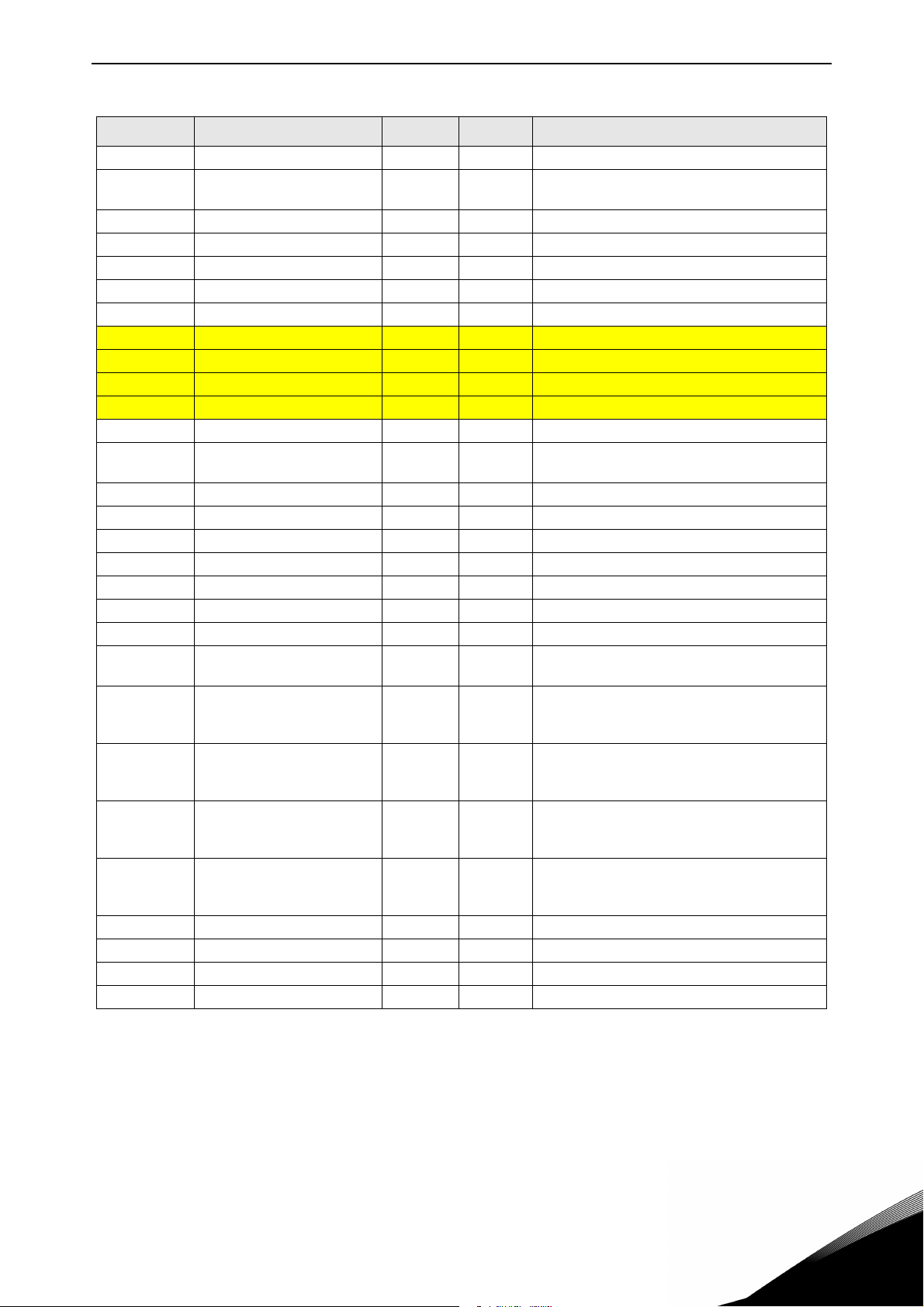
Multi-purpose Control Application vacon • 77
Table 51. Monitoring values, NXP drives
Code Parameter Unit ID Description
V1.21.21 Analogue output 3 % 51 AO3
V1.21.22
V1.21.23 Step Response Hz 1132 Used for Closed Loop speed tuning
V1.21.24 Output power kW 1508 Drive output power in kW
V1.21.25 PT100 4 temperature Cº 69
V1.21.26 PT100 5 temperature Cº 70
V1.21.27 PT100 6 temperature Cº 71
V1.22.1 FB torque reference % 1140 Default control of FB PD In 1
V1.22.2 FB limit scaling % 46 Default control of FB PD In 2
V1.22.3 FB adjust reference % 47 Default control of FB PD In 3
V1.22.4 FB analogue output % 48 Default control of FB PD In 4
V1.22.5 Last Active Fault 37
V1.22.6 Motor Current to FB A 45
V1.22.7 DIN StatusWord 1 56 See page 79
V1.22.8 DIN StatusWord 2 57 See page 79
V1.22.9 Warning 74 Last active warning code
V1.22.10 Fault Word1 1172 See page 79
V1.22.11 Fault Word2 1173 See page 79
V1.22.12 Warning Word1 1174 See page 80
V1.23.1 SystemBus System Status 1601 See page 80
V1.23.2 Total current A 83
V1.23.3.1 Motor current D1 A 1616
V1.23.3.2 Motor current D2 A 1605
V1.23.3.3 Motor current D3 A 1606
V1.23.3.4 Motor current D4 A 1607
V1.23.4.1 StatusWord D1 1615 See page 81
V1.23.4.2 StatusWord D2 1602 See page 81.
V1.23.4.3 StatusWord D3 1603 See page 81.
V1.23.4.4 StatusWord D4 1604 See page 81.
Final Frequency Reference
Closed Loop
Hz 1131 Used for Closed Loop speed tuning
Motor current (drive independent) given with
one decimal point
Total current of the drives in Master Follower
system.
D1: This value is the current of drive number
one power unit.
D2, D3 and D4: Not updated.
D1:This value is the current of drive number
two power unit.
D2, D3 and D4: Not updated.
D1:This value is the current of drive number
three power unit.
D2, D3 and D4: Not updated.
D1: This value is the current of drive number
four power unit.
D2, D3 and D4: Not updated.
24-hour support +358 (0)201 212 575 • Email: vacon@vacon.com
6
Page 80

vacon • 78 Multi-purpose Control Application
6.6.1.1 Digital input statuses: ID15 and ID16
Table 52. Digital input statuses
DIN1/DIN2/DIN3 status DIN4/DIN5/DIN6 status
b0 DIN3 DIN6
b1 DIN2 DIN5
b2 DIN1 DIN4
6
Tel. +358 (0) 201 2121 • Fax +358 (0)201 212 205
Page 81

Multi-purpose Control Application vacon • 79
6.6.1.2 Digital input statuses: ID56 and ID57
Table 53. Digital input statuses
DIN StatusWord 1 DIN StatusWord 2
b0 DIN: A.1 DIN: C.5
b1 DIN: A.2 DIN: C.6
b2 DIN: A.3 DIN: D.1
b3 DIN: A.4 DIN: D.2
b4 DIN: A.5 DIN: D.3
b5 DIN: A.6 DIN: D.4
b6 DIN: B.1 DIN: D.5
b7 DIN: B.2 DIN: D.6
b8 DIN: B.3 DIN: E.1
b9 DIN: B.4 DIN: E.2
b10 DIN: B.5 DIN: E.3
b11 DIN: B.6 DIN: E.4
b12 DIN: C.1 DIN: E.5
b13 DIN: C.2 DIN: E.6
b14 DIN: C.3
b15 DIN: C.4
6.6.1.3 Fault Word 1, ID1172
b0 Overcurrent or IGBT F1, F31, F41
b1 Overvoltage F2
b2 Undervoltage F9
b3 Motor stalled F15
b4 Earth fault F3
b5 Motor underload F17
b6 Drive overtemperature F14
b7 Overtemperature F16, F56, F29
b8 Input phase F10
b11 Keypad or PC control F52
Table 54. Fault Word 1
Fault Comment
b12 Fieldbus F53
b13 SystemBus F59
b14 Slot F54
b15 4 mA F50
24-hour support +358 (0)201 212 575 • Email: vacon@vacon.com
6
Page 82

vacon • 80 Multi-purpose Control Application
6.6.1.4 Fault Word 2, ID1173
Table 55. Fault Word 2
Fault Comment
b2 Encoder F43
b4
b6 External F51
b9 IGBT F31, F41
b10 Brake F58
b14 Main switch open F64
b15
6.6.1.5 Warning Word 1, ID1174
Table 56. Warning Word 1
Fault Comment
b0 Motor stalled W15
b1 Motor overtemperature W16
b2 Motor underload W17
b3 Input phase loss W10
b4 Output phase loss W11
b9 Analogue input < 4mA W50
b10 Not used
b13 Not used
b14 Mechanical brake W58
b15 Keypad or PC Fault/Warning FW52
6.6.1.6 SystemBus Status Word, ID1601
Table 57. SystemBus Status Word
FAL SE TRUE
b0 Reserved
b1 Drive 1 Ready
b2 Drive 1 Running
b3 Drive 1 Fault
b4 Reserved
b5 Drive 2 Ready
b6 Drive 2 Running
b7 Drive 2 Fault
b8 Reserved
b9 Drive 3 Ready
b10 Drive 3 Running
b11 Drive 3 Fault
b12 Reserved
b13 Drive 4 Ready
b14 Drive 4 Running
b15 Drive 4 Fault
6
Tel. +358 (0) 201 2121 • Fax +358 (0)201 212 205
Page 83

Multi-purpose Control Application vacon • 81
6.6.1.7 Follower drive Status Word
Table 58. Follower drive Status Word
FAL SE TRUE
b0 Flux not ready Flux ready (>90 %)
b1 Not in Ready state Ready
b2 Not running Running
b3 No fault Fault
b4 Charge switch state
b5
b6 Run disabled Run enable
b7 No warning Warning
b8
b9
b10
b11 No DC brake DC brake is active
b12 No run request Run request
b13 No limit controls active Limit control active
b14 External brake control OFF External brake control ON
b15 Heartbeat
24-hour support +358 (0)201 212 575 • Email: vacon@vacon.com
6
Page 84

vacon • 82 Multi-purpose Control Application
6.6.1.8 Application Status Word
Application Status Word
Value V1.21.4 Status Word). Status Word is visible on keypad in Multi-Purpose application only. The Status Word of any other application can be read with the NCDrive PC software.
Application
Standard Loc/Rem Multi-Step PID MP PFC
Status Word
b0
b1 Ready Ready Ready Ready Ready Ready
b2 Run Run Run Run Run Run
b3 Fault Fault Fault Fault Fault Fault
b4
b5 No EMStop
b6 Run Enable Run Enable Run Enable Run Enable Run Enable Run Enable
b7 Warning Warning Warning Warning Warning Warning
combines different drive statuses to one data word (see Monitoring
Table 59. Application Status Word content
Application Status Word
(NXP)
b8
b9
b10
b11 DC Brake DC Brake DC Brake DC Brake DC Brake DC Brake
b12 Run request Run request Run request Run request Run request Run request
b13 Limit control Limit control Limit control Limit control Limit control Limit control
b14 Brake control Aux 1
b15 Place B is
active
PID active Aux 2
6
Tel. +358 (0) 201 2121 • Fax +358 (0)201 212 205
Page 85

Multi-purpose Control Application vacon • 83
6.6.2 Basic parameters (Control keypad: Menu M2 -> G2.1)
Table 60. Basic parameters G2.1
Code Parameter Min Max Unit Default Cust ID Note
P2.1.1 Min frequency 0,00 P2.1.2 Hz 0,00 101
NOTE: If f
motor synchronous
P2.1.2 Max frequency P2.1.1 320,00 Hz 50,00 102
P2.1.3 Acceleration time 1 0,1 3000,0 s 3,0 103 0 Hz to Max frequency
P2.1.4 Deceleration time 1 0,1 3000,0 s 3,0 104 Max frequency to 0 Hz
P2.1.5 Current limit
P2.1.6
Nominal voltage of the
motor
0,1 x I
180 690 V
2 x I
H
H
A
I
L
NX2: 230V
NX5: 400V
NX6: 690V
speed, check suitability
for motor and drive system
107
Check the rating plate of
the motor. Note also
110
used connection Delta/
Star.
> than the
max
P2.1.7
P2.1.8
P2.1.9
P2.1.10 Motor cos 0,30 1,00 0,85 120
P2.1.11 I/O Reference 0 15/16 0 117
P2.1.12
P2.1.13
Nominal frequency of
the motor
Nominal speed of the
motor
Nominal current of the
motor
Keypad control refer-
ence
Fieldbus control refer-
ence
8,00 320,00 Hz 50,00 111
24 20 000 rpm 1440 112
0,1 x I
0 9 8 121
0 9 9 122 See P2.1.12
2 x I
H
A
H
I
H
113
Check the rating plate of
the motor
The default applies for a
4-pole motor and a nominal size frequency converter.
Check the rating plate of
the motor.
Check the rating plate of
the motor
0 = AI1
1 = AI2
2 = AI1+AI2
3 = AI1-AI2
4 = AI2-AI1
5 = AI1xAI2
6 = AI1 Joystick
7 = AI2 Joystick
8 = Keypad
9 = Fieldbus
10 = Motor potentiome
ter
11 = AI1, AI2 minimum
12 = AI1, AI2 maximum
13 = Max frequency
14 = AI1/AI2 selection
15 = Encoder 1
16 = Encoder 2 (NXP
only)
0 = AI1
1 = AI2
2 = AI1+AI2
3 = AI1-AI2
4 = AI2-AI1
5 = AI1xAI2
6 = AI1 Joystick
7 = AI2 Joystick
8 = Keypad
9 = Fieldbus
24-hour support +358 (0)201 212 575 • Email: vacon@vacon.com
6
Page 86

vacon • 84 Multi-purpose Control Application
Table 60. Basic parameters G2.1
Code Parameter Min Max Unit Default Cust ID Note
P2.1.14
P2.1.15 Preset speed 1 0,00 P2.1.2 Hz 10,00 105 Multi-step speed 1
P2.1.16 Preset speed 2 0,00 P2.1.2 Hz 15,00 106 Multi-step speed 2
P2.1.17 Preset speed 3 0,00 P2.1.2 Hz 20,00 126 Multi-step speed 3
P2.1.18 Preset speed 4 0,00 P2.1.2 Hz 25,00 127 Multi-step speed 4
P2.1.19 Preset speed 5 0,00 P2.1.2 Hz 30,00 128 Multi-step speed 5
P2.1.20 Preset speed 6 0,00 P2.1.2 Hz 40,00 129 Multi-step speed 6
P2.1.21 Preset speed 7 0,00 P2.1.2 Hz 50,00 130 Multi-step speed 7
Jogging speed refer-
ence
0,00 P2.1.2 Hz 5,00 124 See ID413.
6.6.3 Input signals
6.6.3.1 Basic Settings (Control keypad: Menu M2 -> G2.2.1)
Table 61. Input signals: basic settings, G2.2.1
Code Parameter Min Max Unit Default Cust ID Note
P2.2.1.1
P2.2.1.2
P2.2.1.3
P2.2.1.4 Adjust input 0 5 0 493
P2.2.1.5 Adjust minimum 0,0 100,0 % 0,0 494
P2.2.1.6 Adjust maximum 0,0 100,0 % 0,0 495
Start/Stop logic
selection
Motor potentiometer
ramp time
Motor potentiometer
frequency reference
memory reset
07 0 300
0,1 2000,0 Hz/s 10,0 331
02 1 367
Start signal 1
(Default:
DIN1)
0
Start fwd
1
Start/Stop
2
Start/Stop
3
Start pulse
4
Start
5
Start fwd*
6
Start*/Stop
7
Start*/Stop
0 = No reset
1 = Reset if stopped or powered
down
2 = Reset if powered down
0 = Not used
1 = AI1
2 = AI2
3 = AI3
4 = AI4
5 = Fieldbus (see group G2.9)
Start signal 2
(Default:
DIN2)
Start rvs
Reverse
Run enable
Stop pulse
Mot.pot.UP
Start rvs*
Reverse
Run enable
6
Tel. +358 (0) 201 2121 • Fax +358 (0)201 212 205
Page 87
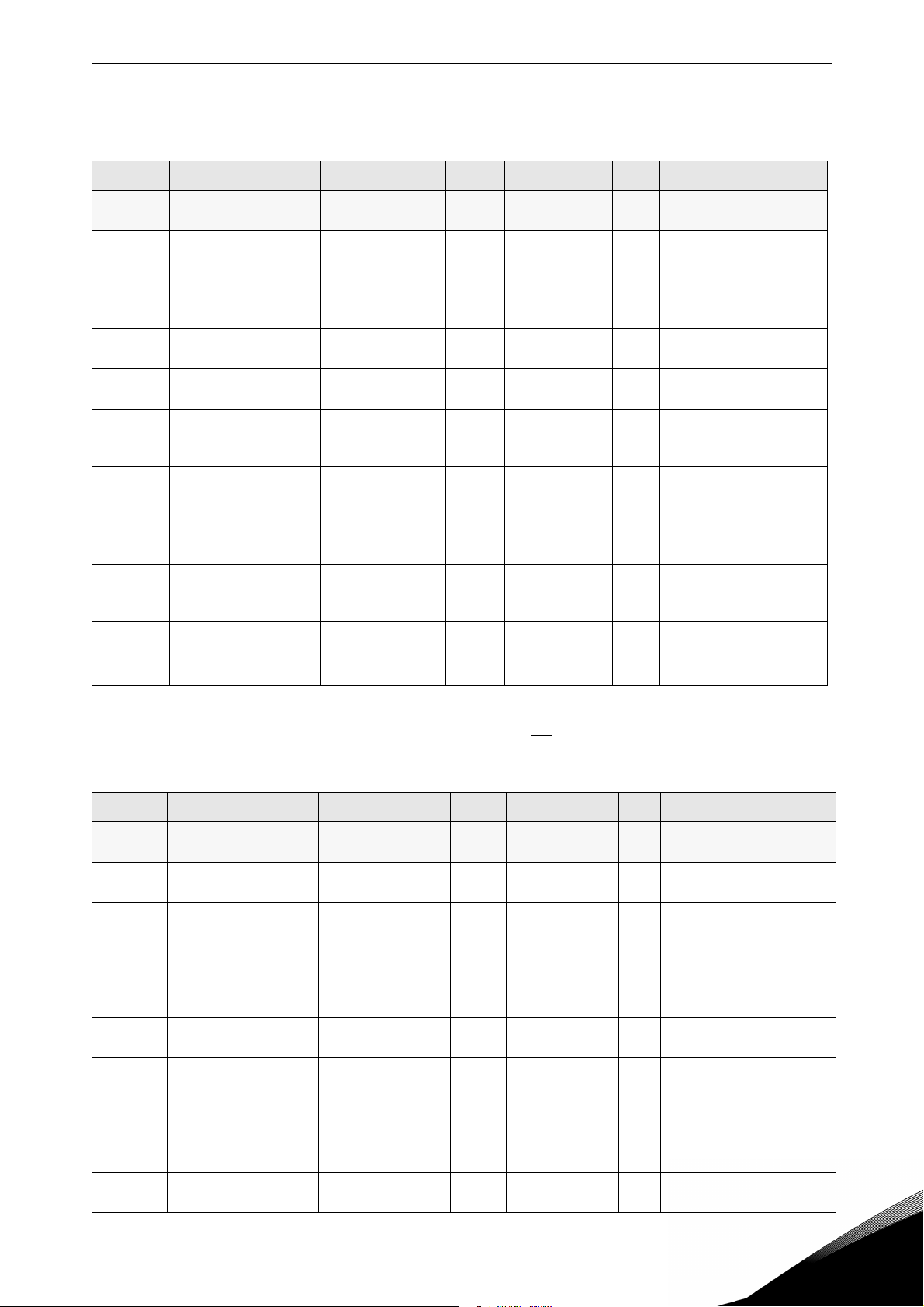
Multi-purpose Control Application vacon • 85
6.6.3.2 Analogue input 1 (Control keypad: Menu M2 -> G2.2.2)
Table 62. Analogue input 1 parameters, G2.2.2
Code Parameter Min Max Unit Default Cust ID Note
P2.2.2.1 AI1 signal selection 0.1 E.10 A.1 377
P2.2.2.2 AI1 filter time 0,00 10,00 s 0,10 324 0 = No filtering
P2.2.2.3 AI1 signal range 0 3 0 320
P2.2.2.4
P2.2.2.5
P2.2.2.6
P2.2.2.7
P2.2.2.8 AI1 joystick hysteresis 0,00 20,00 % 0,00 384
P2.2.2.9 AI1 sleep limit 0,00 100,00 % 0,00 385
P2.2.2.10 AI1 sleep delay 0,00 320,00 s 0,00 386
P2.2.2.11 AI1 joystick offset -100,00 100,00 % 0,00 165
AI1 custom minimum
setting
AI1 custom maximum
setting
AI1 reference scaling,
minimum value
AI1 reference scaling,
maximum value
-160,00 160,00 % 0,00 321
-160,00 160,00 % 100,00 322 e.g.9 V = 90 %
0,00 320,00 Hz 0,00 303
0,00 320,00 Hz 0,00 304
TTF programming. See
chapter 6.4
0 = 0-10 V (0-20 mA*)
1 = 2-10 V (4-20 mA*)
2 = -10V…+10V*
3 = Custom range*
% of input signal range.
e.g.3 V = 30 %
Selects the frequency
that corresponds to the
min. reference signal
Selects the frequency
that corresponds to the
max. reference signal
Dead zone for joystick
input
Drive goes to sleep mode
if input is below this limit
for set time.
Press ‘Enter’ for 1s to set
offset, ‘Reset’ to set 0,00
*Remember to place jumpers of block X2 accordingly. See the product's User's Manual
6.6.3.3
Analogue input 2 (Control keypad: Menu M2 -> G2.2.3)
Table 63. Analogue input 2 parameters, G2.2.3
Code Parameter Min Max Unit Default Cust ID Note
P2.2.3.1 AI2 signal selection 0.1 E.10 A.2 388
P2.2.3.2
P2.2.3.3 AI2 signal range 0 3 1 325
P2.2.3.4
P2.2.3.5
P2.2.3.6
P2.2.3.7
P2.2.3.8 AI2 joystick hysteresis 0,00 20,00 % 0,00 395
AI2 filter timeAI2 filter
time
AI2 custom minimum
setting
AI2 custom maximum
setting
AI2 reference scaling,
minimum value
AI2 reference scaling,
maximum value
0,00 10,00 s 0,10 329 0 = No filtering
-160,00 160,00 % 20,00 326
-160,00 160,00 % 100,00 327 e.g. 18 mA = 90 %
0,00 320,00 Hz 0,00 393
0,00 320,00 Hz 0,00 394
TTF programming. See
chapter 6.4.
0 = 0-20 mA (0-10 V *)
1 = 4-20 mA (2-10 V *)
2 = -10V…+10V*
3 = Custom range*
% of input signal range.
e.g. 2 mA = 10 %
Selects the frequency that
corresponds to the min.
reference signal
Selects the frequency that
corresponds to the max.
reference signal
Dead zone for joystick
input, e.g. 10 % = +/- 5 %
24-hour support +358 (0)201 212 575 • Email: vacon@vacon.com
6
Page 88

vacon • 86 Multi-purpose Control Application
Table 63. Analogue input 2 parameters, G2.2.3
Code Parameter Min Max Unit Default Cust ID Note
Drive goes to sleep mode if
P2.2.3.9 AI2 sleep limit 0,00 100,00 % 0,00 396
P2.2.3.10 AI2 sleep delay 0,00 320,00 s 0,00 397
P2.2.3.11 AI2 joystick offset -100,00 100,00 % 0,00 166
input is below this limit for
set time.
Press ‘Enter’ for 1s to set
offset, ‘Reset’ to set 0,00
6.6.3.4 Analogue input 3 (Control keypad: Menu M2 -> G2.2.4)
Table 64. Analogue input 3 parameters, G2.2.4
Code Parameter Min Max Unit Default Cust ID Note
P2.2.4.1
P2.2.4.2 AI3 filter time 0,00 10,00 s 0,00 142 0 = No filtering
P2.2.4.3 AI3 signal range 0 3 0 143
P2.2.4.4
P2.2.4.5
P2.2.4.6
AI3 signal selec-
tion
AI3 custom mini-
mum setting
AI3 custom maxi-
mum setting
AI3 signal inver-
sion
0.1 E.10 0.1 141
-160,00 160,00 % 0,00 144
-160,00 160,00 % 100,00 145 e.g. 18 mA = 90 %
01 0 151
TTF programming. See chapter
6.4
0 = 0-20 mA (0-10 V *)
1 = 4-20 mA (2-10 V *)
2 = -10V…+10V*
3 = Custom range*
% of input signal range. e.g. 2
mA = 10 %
0 = Not inverted
1 = Inverted
*Remember to place jumpers of block X2 accordingly. See the product's User's Manual.
6.6.3.5
Analogue input 4 (Control keypad: Menu M2 -> G2.2.5)
Table 65. Analogue input 4 parameters, G2.2.5
Code Parameter Min Max Unit Default Cust ID Note
P2.2.5.1
P2.2.5.2 AI4 filter time
P2.2.5.3
P2.2.5.4
P2.2.5.5
P2.2.5.6 AI4 signal inversion 0 1 0
AI4 signal selection 0 0.1 152
0,00 10,00 s 0,00 153
AI4 signal range
AI4 custom minimum
setting
AI4 custom maximum
setting
0 3 1 154
-160,00 160,00 % 20,00 155
-160,00 160,00 % 100,00 156 e.g. 18 mA = 90 %
TTF programming. See
chapter 6.4
0 = No filtering
0 =0-20 mA (0-10 V *)
1 = 4-20 mA (2-10 V *)
2 = -10V…+10V*
3 = Custom range*
% of input signal range.
e.g. 2 mA = 10 %
0 = Not inverted
162
1 = Inverted
6
Tel. +358 (0) 201 2121 • Fax +358 (0)201 212 205
Page 89

Multi-purpose Control Application vacon • 87
6.6.3.6 Free analogue input, signal selection (Keypad: Menu M2 -> G2.2.6)
Table 66. Free analogue input signal selection, G2.2.6
Code Parameter Min Max Unit Default Cust ID Note
0 = Not used
1 = AI1
2 = AI2
P2.2.6.1 Scaling of current limit 0 5 0 399
P2.2.6.2
P2.2.6.3
P2.2.6.4
P2.2.6.5
Scaling of DC-braking
current
Scaling of acc./dec.
times
Scaling of torque
supervision limit
Scaling of torque limit 0 5 0 485
0 5 0 400
0 5 0 401
0 5 0 402
3 = AI3
4 = AI4
5 = FB Limit Scaling
See group G2.9
As parameter P2.2.6.1
Scaling from 0 to ID507
As parameter P2.2.6.1
Scales active ramp from
100 % to 10 %.
As parameter P2.2.6.1
Scaling from 0 to ID348
As parameter P2.2.6.1
Scaling from 0 to (ID609
(NXS) or ID1287 (NXP))
NXP drives only
P2.2.6.6
P2.2.6.7
P2.2.6.8
Scaling of generator
torque limit
Scaling of motoring
power limit
Scaling of generator
power limit
0 5 0 1087
0 5 0 179
0 5 0 1088
6.6.3.7 Digital inputs (Control keypad: Menu M2 -> G2.2.4)
As parameter P2.2.6.1
Scaling from 0 to ID1288
As parameter P2.2.6.1
Scaling from 0 to ID1289
As parameter P2.2.6.1
Scaling from 0 to ID1290
Use TTF programming method for all these parameters. See chapter
Table 67. Digital input signals, G2.2.4
Code Parameter Min Default Cust ID Note
P2.2.7.1 Start signal 1 0.1 A.1 403 See P2.2.1.1.
P2.2.7.2 Start signal 2 0.1 A.2 404 See P2.2.1.1.
P2.2.7.3 Run enable 0.1 0.2 407 Motor start enabled (cc)
P2.2.7.4 Reverse 0.1 0.1 412
P2.2.7.5 Preset speed 1 0.1 0.1 419
P2.2.7.7 Preset speed 3 0.1 0.1 421
P2.2.7.8
P2.2.7.9
P2.2.7.10 Fault rese 0.1 A.3 414 All faults reset (cc)
P2.2.7.11 External fault (close) 0.1 A.5 405 Ext. fault (F51) displayed (cc)
P2.2.7.12 External fault (open) 0.1 0.2 406 Ext. fault (F51) displayed (oc)
P2.2.7.13 Acc/Dec time selection 0.1 A.6 408
P2.2.7.14 Acc/Dec prohibit 0.1 0.1 415 Acc/Dec prohibited (cc)
P2.2.7.15 DC braking 0.1 0.1 416 DC braking active (cc)
Motor potentiometer refer-
ence DOWN
Motor potentiometer refer-
ence UP
0.1 0.1 417 Mot.pot. reference decreases (cc)
0.1 0.1 418 Mot.pot. reference increases (cc)
Direction forward (oc)
Direction reverse (cc)
See preset speeds in
Basic Parameters (G2.1)P2.2.7.6 Preset speed 2 0.1 0.1 420
Acc/Dec time 1 (oc)
Acc/Dec time 2 (cc)
24-hour support +358 (0)201 212 575 • Email: vacon@vacon.com
6
Page 90

vacon • 88 Multi-purpose Control Application
Table 67. Digital input signals, G2.2.4
Code Parameter Min Default Cust ID Note
P2.2.7.16 Jogging speed 0.1 A.4 413
P2.2.7.17 AI1/AI2 selection 0.1 0.1 422
P2.2.7.18 Control from I/O terminal 0.1 0.1 409
P2.2.7.19 Control from keypad 0.1 0.1 410 Force control place to keypad (cc)
P2.2.7.20 Control from fieldbus 0.1 0.1 411 Force control place to fieldbus (cc)
P2.2.7.21
P2.2.7.22 Motor control mode 1/2 0.1 0.1 164
Parameter set 1/set 2 selec-
tion
0.1 0.1 496
Jogging speed selected for frequency reference (cc)
cc = AI2 is used as reference, when
ID117 = 14
Force control place to I/O terminal
(cc)
Closed cont.=Set 2 is used
Open cont.= Set 1 is used
Closed cont.= Mode 2 is used
Open cont.= Mode 1 is used
See par 2.6.1, 2.6.12
NXP drives only
P2.2.7.23 Cooling monitor 0.1 0.2 750 Used with liquid-cooled unit
P2.2.7.24 External brake acknowledge 0.1 0.2 1210
P2.2.7.26 Enable inching 0.1 0.1 532 Enables Inching function
P2.2.7.27 Inching reference 1 0.1 0.1 530
P2.2.7.28 Inching reference 2 0.1 0.1 531
P2.2.7.29 Reset encoder counter 0.1 0.1 1090
P2.2.7.30 Emergency stop 0.1 0.2 1213 Low signal activates EM
P2.2.7.31 Master Follower mode 2 0.1 0.1 1092
P2.2.7.32
Input switch acknowledge-
ment
0.1 0.2 1209 Low signal generates fault (F64)
Monitoring signal from mechanical
brake
Inching reference 1. (Default Forward 2 Hz. See P2.4.15) This will
start the drive
Inching reference 2. (Default Forward 2 Hz. See P2.4.16) This will
start the drive
Reset Shaft Rounds and Angle (see
6-3)
See chapter 6.5 and parameters
P2.11.1-P2.11.7
6
cc = closing contact
oc = opening contact
Tel. +358 (0) 201 2121 • Fax +358 (0)201 212 205
Page 91

Multi-purpose Control Application vacon • 89
6.6.4 Output signals
6.6.4.1 Delayed digital output 1 (Keypad: Menu M2 -> G2.3.1)
Table 68. Delayed digital output 1 parameters, G2.3.1
Code Parameter Min Max Unit Default Cust ID Note
P2.3.1.1
P2.3.1.2
P2.3.1.3
P2.3.1.4
Digital output 1
signal selection
Digital output 1
function
Digital output
1 on delay
Digital output
1 off delay
0.1 E.10 0.1 486
0 26 1 312
320,0
0,00
0,00
320,0
s 0,00 487 0,00 = On delay not in use
0
0,00
s
0
488 0,00 = Off delay not in use
TTF programming. See chapter 6.4 .
Possible to invert with ID1084 (NXP only)
0 = Not used
1 = Ready
2 = Run
3 = Fault
4 = Fault inverted
5 = FC overheat warning
6 = Ext. fault or warning
7 = Ref. fault or warning
8 = Warning
9 = Reverse
10 = Jogging spd selected
11 = At speed
12 = Mot. regulator active
13 = Freq. limit 1 superv.
14 = Freq. limit 2 superv.
15 = Torque limit superv.
16 = Ref. limit supervision
17 = External brake control
18 = I/O control place act.
19 = FC temp. limit superv.
20 = Reference inverted
21 = Ext. brake control inverted
22 = Therm. fault or warn.
23 = AI supervision
24 = Fieldbus DIN 1
25 = Fieldbus DIN 2
26 = Fieldbus DIN 3
6.6.4.2 Delayed digital output 2 (Keypad: Menu M2 -> G2.3.2)
Table 69. Delayed digital output 2 parameters, G2.3.2
Code
P2.3.2.1
P2.3.2.2
P2.3.2.3
P2.3.2.4
24-hour support +358 (0)201 212 575 • Email: vacon@vacon.com
Parameter
Digital output 2
signal selection
Digital output 2
function
Digital output 2 on
delay
Digital output 2 off
delay
Min Max Unit Default Cust ID Note
0.1 E.10 0.1 489
0 26 0 490 See P2.3.1.2
0,00 320,00 s 0,00 491
0,00 320,00 s 0,00 492
TTF programming. See
chapter 6.4 .
Possible to invert with
ID1084 (NXP only)
0,00 = On delay not in use
0,00 = Off delay not in use
6
Page 92

vacon • 90 Multi-purpose Control Application
6.6.4.3 Digital output signals (Control keypad: Menu M2 -> G2.3.3)
Use TTF programming method for all these parameters. See chapter.
Table 70. Digital output signals, G2.3.3
Code Parameter Min Default Cust ID Note
P2.3.3.1 Ready 0.1 A.1 432 Ready to Run
P2.3.3.2 Run 0.1 B.1 433 Running
P2.3.3.3 Fault 0.1 B.2 434 Drive in fault state
P2.3.3.4 Inverted fault 0.1 0.1 435 Drive not in fault state
P2.3.3.5 Warning 0.1 0.1 436 Warning active
P2.3.3.6 External fault 0.1 0.1 437 External fault active
P2.3.3.7 Reference fault/warning 0.1 0.1 438 4 mA fault or warning active
P2.3.3.8 Overtemperature warning 0.1 0.1 439 Drive overtemperature active
P2.3.3.9 Reverse 0.1 0.1 440 Output frequency < 0 Hz
P2.3.3.10 Unrequested direction 0.1 0.1 441 Actual direction <> requested direction
P2.3.3.11 At speed 0.1 0.1 442 Reference = Output frequency
P2.3.3.12 Jogging speed 0.1 0.1 443 Jogging or preset speed command active
P2.3.3.13 I/O control place 0.1 0.1 444 IO control active
P2.3.3.14 External brake control 0.1 0.1 445
P2.3.3.15
P2.3.3.16
P2.3.3.17
P2.3.3.18 Reference limit supervision 0.1 0.1 449 See ID350.
P2.3.3.19 Temperature limit supervision 0.1 0.1 450 Drive temperature supervision. See ID354.
P2.3.3.20 Torque limit supervision 0.1 0.1 451 See ID348.
P2.3.3.21 Themistor fault or warning 0.1 0.1 452
P2.3.3.22
P2.3.3.23 Motor regulator activation 0.1 0.1 454
P2.3.3.24 Fieldbus DIN 1 0.1 0.1 455 See fieldbus manual
P2.3.3.25 Fieldbus DIN 2 0.1 0.1 456 See fieldbus manual
P2.3.3.26 Fieldbus DIN 3 0.1 0.1 457 See fieldbus manual
P2.3.3.27 Fieldbus DIN 4 0.1 0.1 169 See fieldbus manual
P2.3.3.28 Fieldbus DIN 5 0.1 0.1 170 See fieldbus manual
External brake control,
inverted
Output frequency limit 1
supervision
Output frequency limit 2
supervision
Analogue input supervision
limit
0.1 0.1 446
0.1 0.1 447 See ID315.
0.1 0.1 448 See ID346.
0.1 0.1 463
See explanations on page 179.
See ID356
6
NXP drives only
P2.3.3.29 DC ready pulse 0.1 0.1 1218 For external DC charger
P2.3.3.30 Safe Disable Active 0.1 0.1 756
Be ABSOLUTELY sure not to connect two functions to one and same
output
in order to avoid function overruns and to ensure flawless
operation.
Tel. +358 (0) 201 2121 • Fax +358 (0)201 212 205
Page 93

Multi-purpose Control Application vacon • 91
6.6.4.4 Limit settings (Control keypad: Menu M2 -> G2.3.4)
Table 71. Limit settings, G2.3.4
Code Parameter Min Max Unit Default Cust ID Note
0 = Not used
P2.3.4.1
P2.3.4.2
P2.3.4.3
P2.3.4.4
P2.3.4.5 Torque limit supervision 0 3 0 348
P2.3.4.6
P2.3.4.7 Reference limit supervision 0 2 0 350
P2.3.4.8
P2.3.4.9
P2.3.4.10
P2.3.4.11 FC temperature supervision 0 2 0 354
P2.3.4.12
P2.3.4.13 Analogue supervision signal 0 4 0 356
P2.3.4.14
P2.3.4.15
NXP drives only
P2.3.4.16 Brake On/Off Current Limit 0
Output frequency limit 1
supervision
Output frequency limit 1;
Supervised value
Output frequency limit 2
supervision
Output frequency limit 2;
Supervised value
Torque limit supervision
value
Reference limit supervision
value
External
brake-off delay
External
brake-on delay
FC temperature supervised
value
Analogue supervision low
limit
Analogue supervision high
limit
03 0 315
0,00 320,00 Hz 0,00 316
04 0 346
0,00 320,00 Hz 0,00 347
-300,0 300,0 % 100,0 349
0,0 100,0 % 0,0 351
0,0 100,0 s 0,5 352 From brake-off limits
0,0 100,0 s 1,5 353
–10 100
0,00 100,00 % 10,00 357 DO Off limit. See P2.3.3.22
0,00 100,00 % 90,00 358 DO Off limit. See P2.3.3.22
2 x I
C
A 0 1085
H
40 355
1 = Low limit supervision
2 = High limit supervision
3 = Brake-on control
0 = Not used
1 = Low limit supervision
2 = High limit supervision
3 = Brake-off control
4 = Brake on/off-control
0 = Not used
1 = Low limit supervision
2 = High limit supervision
3 = Brake-off control
For brake control absolute
values are used
0 = Not used
1 = Low limit
2 = High limit
0,0 = Min frequency
100,0 = Max frequency
From Run request. Use time
longer than P2.1.4
0 = Not used
1 = Low limit
2 = High limit
0 = Not used
1 = AI1
2 = AI2
3 = AI3
4 = AI4
Brake is closed and kept
closed if current is below
this value.
24-hour support +358 (0)201 212 575 • Email: vacon@vacon.com
6
Page 94

vacon • 92 Multi-purpose Control Application
6.6.4.5 Analogue output 1 (Control keypad: Menu M2 -> G2.3.5)
Table 72. Analogue output 1 parameters, G2.3.5
Code Parameter Min Max Unit Default Cust ID Note
P2.3.5.1
P2.3.5.2
P2.3.5.3
P2.3.5.4
P2.3.5.5
P2.3.5.6
P2.3.5.7
Analogue output 1
signal selection
Analogue output 1
function
Analogue output 1 fil-
ter time
Analogue output 1
inversion
Analogue output 1
minimum
Analogue output 1
scale
Analogue output 1
offset
0.1 E.10 A.1 464 TTF programming. See chapter 6.4
0 = Not used (20 mA / 10 V)
min
max
nMotor
nMotor
nMotor
nMotor
- f
)
max
max
)
)
)
)
)
Nmot
1 = Output freq. (0—f
2 = Freq. reference (0—f
3 = Motor speed (0—Motor nominal
speed)
4 = Motor current (0—I
5 = Motor torque (0—T
6 = Motor power (0—P
0 15 1 307
0,00 10,00 s 1,00 308 0 = No filtering
0 1 0 309
0 1 0 310
10 1000 % 100 311
-100,00 100,00 % 0,00 375
7 = Motor voltage (0-U
8 = DC-link volt (0—1000V)
9 = AI1
10 = AI2
11 = Output freq. (f
12 = Motor torque (–2…+2xT
13 = Motor power (–2…+2xT
14 = PT100 temperature
15 = FB analogue output
Pr ocessData4 (NXS)
0 = Not inverted
1 = Inverted
0 = 0 mA (0 V)
1 = 4 mA (2 V)
)
Nmot
)
)
6.6.4.6 Analogue output 2 (Control keypad: Menu M2 -> G2.3.6)
Table 73. Analogue output 2 parameters, G2.3.6
Code Parameter Min Max Unit Default Cust ID Note
P2.3.6.1
P2.3.6.2
P2.3.6.3
P2.3.6.4
P2.3.6.5
P2.3.6.6
P2.3.6.7
Analogue output 2 sig-
nal selection
Analogue output 2
function
Analogue output 2 fil-
ter time
Analogue output 2
inversion
Analogue output 2
minimum
Analogue output 2
scale
Analogue output 2 off-
set
0.1 E.10 0.1 471
0 15 4 472 See P2.3.5.2
0,00 10,00 s 1,00 473 0 = No filtering
01 0 474
01 0 475
10 1000 % 100 476
-100,00 100,00 % 0,00 477
TTF programming. See
chapter 6.4.
0 = Not inverted
1 = Inverted
0 = 0 mA (0 V)
1 = 4 mA (2 V)
6
Tel. +358 (0) 201 2121 • Fax +358 (0)201 212 205
Page 95

Multi-purpose Control Application vacon • 93
6.6.4.7 Analogue output 3 (Control keypad: Menu M2 -> G2.3.7)
Table 74. Analogue output 3 parameters, G2.3.7
Code Parameter Min Max Unit Default Cust ID ID
P2.3.7.1
P2.3.7.2 Analogue output 3 function 0 15 5 479 See P2.3.5.2
P2.3.7.3 Analogue output 3 filter time 0,00 10,00 s 1,00 480 0 = No filtering
P2.3.7.4 Analogue output 3 inversion 0 1 0 481
P2.3.7.5 Analogue output 3 minimum 0 1 0 482
P2.3.7.6 Analogue output 3 scale 10 1000 % 100 483
P2.3.7.7 Analogue output 3 offset -100,00 100,00 % 0,00 484
Analogue output 3 signal
selection
0.1 E.10 0.1 478
TTF programming
See chapter 6.2 and 6.4
0 = Not inverted
1 = Inverted
0 = 0 mA (0 V)
1 = 4 mA (2 V)
24-hour support +358 (0)201 212 575 • Email: vacon@vacon.com
6
Page 96

vacon • 94 Multi-purpose Control Application
6.6.5 Drive control parameters (Control keypad: Menu M2 -> G2.4)
Table 75. Drive control parameters, G2.4
Code Parameter Min Max Unit Default Cust ID Note
P2.4.1 Ramp 1 shape 0,0 10,0 s 0,1 500
P2.4.2 Ramp 2 shape 0,0 10,0 s 0,0 501
P2.4.3 Acceleration time 2 0,1 3000,0 s 10,0 502
P2.4.4 Deceleration time 2 0,1 3000,0 s 10,0 503
P2.4.5 Brake chopper 0 4 0 504
P2.4.6 Start function 0 2 0 505
P2.4.7 Stop function 0 3 0 506
P2.4.8 DC braking current 0
P2.4.9
P2.4.10
P2.4.11
P2.4.12 Flux brake 0 1 0 520
P2.4.13 Flux braking current 0
NXP drives only
DC braking time
at stop
Frequency to start DC
braking during
ramp stop
DC braking time
at start
0,00 600,00 s 0,00 508 0 = DC brake is off at stop
0,10 10,00 Hz 1,50 515
0,00 600,00 s 0,00 516 0 = DC brake is off at start
I
L
I
L
0,7 x I
A
A
H
I
H
507
519
0 = Linear
>0 = S-curve ramp time
0 = Linear
>0 = S-curve ramp time
0 = Disabled
1 = Used when running
2 = External brake chopper
3 = Used when stopped/
running
4 = Used when running (no
testing)
0 = Ramp
1 = Flying start
2 = Conditional flying start
0 = Coasting
1 = Ramp
2 = Ramp+Run enable coast
3 = Coast+Run enable ramp
0 = Off
1 = On
6
P2.4.14
P2.4.15 Inching reference 1 -320,00 320,00 Hz 2,00 1239
P2.4.16 Inching reference 2 -320,00 320,00 Hz -2,00 1240
P2.4.17 Inching ramp 0,1 3200,0 s 1,0 1257
P2.4.18 Emergency stop mode 0 1 0 1276
P2.4.19 Control options 0 65536 0 1084
DC-brake current at
stop
0
I
L
0,1 x I
A
H
1080
Tel. +358 (0) 201 2121 • Fax +358 (0)201 212 205
0 = Coasting
1 = Ramp
Change allowed only in Stop
state
Page 97

Multi-purpose Control Application vacon • 95
6.6.6 Prohibit frequency parameters (Control keypad: Menu M2 -> G2.5)
Table 76. Prohibit frequencies, (G2.5)
Code Parameter Min Max Unit Default Cust ID Note
P2.5.1 Prohibit frequency range 1 low limit -1,00 320,00 Hz 0,00 509 0 = Not used
P2.5.2 Prohibit frequency range 1 high limit 0,00 320,00 Hz 0,00 510 0 = Not used
P2.5.3 Prohibit frequency range 2 low limit 0,00 320,00 Hz 0,00 511 0 =Not used
P2.5.4 Prohibit frequency range 2 high limit 0,00 320,00 Hz 0,00 512 0 = Not used
P2.5.5 Prohibit frequency range 3 low limit 0,00 320,00 Hz 0,00 513 0 = Not used
P2.5.6 Prohibit frequency range 3 high limit 0,00 320,00 Hz 0,00 514 0 = Not used
P2.5.7 Prohibit acc./dec. ramp 0,1 10,0 x 1,0 518
6.6.7 Motor control parameters (Control keypad: Menu M2
-> G2.6)
Table 77. Motor control parameters
Code Parameter Min Max Unit Default Cust ID Note
0 = Frequency control
1 = Speed control
P2.6.1 Motor control mode 0 2/4 0 600
P2.6.2 U/f optimisation 0 1 0 109
P2.6.3 U/f ratio selection 0 3 0 108
P2.6.4 Field weakening point 8,00 320,00 Hz 50,00 602
P2.6.5
P2.6.6
P2.6.7
P2.6.8
P2.6.9 Switching frequency 1,0 Varies kHz Varies 601 See 8-14 for exact values
P2.6.10 Overvoltage controller 0 2 1 607
P2.6.11
P2.6.12
P2.6.13
P2.6.14
P2.6.15 Load drooping 0,00 100,00 % 0,00 620
Voltage at field weak-
ening point
U/f curve midpoint
frequency
U/f curve midpoint
voltage
Output voltage at zero
frequency
Undervoltage control-
ler
Motor control
mode 2
Speed controller
P gain (open loop)
Speed controller
I gain (open loop)
10,00 200,00 % 100,00 603
0,00 P2.6.4 Hz 50,00 604
0,00 100,00 % 100,00 605
0,00 40,00 % Varies 606
02 1 608
0 4 2 521 See P2.6.1
0 32767 3000 637
0 32767 300 638
2 = Torque control
Additionally for NXP:
3 = Closed loop speed ctrl
4 = Closed loop torque ctrl
0 = Not used
1 = Automatic torque boost
0 = Linear
1 = Squared
2 = Programmable
3 = Linear with flux optim.
n% x U
nmot
n% x U
nmot
Parameter max. value = P2.6.5
n% x U
nmot
0 = Not used
1 = Used (no ramping)
2 = Used (ramping)
0 = Not used
1 = Used (no ramping)
2 = Used (ramping to zero)
24-hour support +358 (0)201 212 575 • Email: vacon@vacon.com
6
Page 98

vacon • 96 Multi-purpose Control Application
Table 77. Motor control parameters
Code Parameter Min Max Unit Default Cust ID Note
0 = No action
1 = Identification w/o run
P2.6.16 Identification 0 1/3 0 631
Additionally for NXP:
2 = Identification with run
3 = Encoder ID Run (PMSM)
NXP drives only
P2.6.17 Restart delay 0,000 65,535 s Varies 1424 OL delay for coasting stop
P2.6.18 Load drooping time 0 32000 ms 0 656 For dynamic changes
P2.6.19
P2.6.20
P2.6.21 Generator torque limit 0,0 300,0 % 300,0 1288
P2.6.22 Motoring torque limit 0,0 300,0 % 300,0 1287
Negative frequency
limit
Positive frequency
limit
-
320,00
-
320,00
320,00 Hz -320,00 1286
320,00 Hz 320,00 1285
Alternative limit for negative
direction
Alternative limit for positive direction
6.6.7.1 Closed Loop parameters (Control keypad: Menu M2 ->G2.6.23)
NOTE: Depending on the application version, the parameter code may appear as 2.6.17.xx instead
of 2.6.23.xx
Table 78. Closed Loop motor control parameters (G2.6.23)
Code Parameter Min Max Unit Default Cust ID Note
P2.6.23.1 Magnetizing current 0,00
P2.6.23.2 Speed control P 1 1000 30 613
P2.6.23.3 Speed control I time -32000 3200,0 ms 100,0 614
P2.6.23.5 Acceleration compensation 0,00 300,00 s 0,00 626
P2.6.23.6 Slip adjust 0 500 % 75 619
P2.6.23.7 Magnetizing current at start 0
P2.6.23.8 Magnetizing time at start 0 32000 ms 0 628
P2.6.23.9 0-speed time at start 0 32000 ms 100 615
P2.6.23.10 0-speed time at stop 0 32000 ms 100 616
P2.6.23.11 Start-up torque 0 3 0 621
P2.6.23.12 Start-up torque FWD –300,0 300,0 % 0,0 633
P2.6.23.13 Start-up torque REV –300,0 300,0 % 0,0 634
P2.6.23.15 Encoder filter time 0,0 100,0 ms 0,0 618
P2.6.23.17
P2.6.23.19 Generator power limit 0,0 300,0 % 300,0 1290
P2.6.23.20 Motoring power limit 0,0 300,0 % 300,0 1289
P2.6.23.21 Negative torque limit 0,0 300,0 % 300,0 645
P2.6.23.22 Positive torque limit 0,0 300,0 % 300,0 646
P2.6.23.23 Flux off delay -1 32000 s 0 1402 -1 = Always
P2.6.23.24 Stop state flux 0,0 150,0 % 100,0 1401
P2.6.23.25 SPC f1 point 0,00 320,00 Hz 0,00 1301
P2.6.23.26 SPC f0 point 0,00 320,00 Hz 0,00 1300
P2.6.23.27 SPC Kp f0 0 1000 % 100 1299
Current control
P gain
0,00 100,00 % 40,00 617
2 x I
I
A 0,00 612 If zero internally calculated
H
Negative value uses 1 ms
accuracy instead of 0,1 ms
L
A 0,00 627
0 = Not used
1 = Torque memory
2 = Torque reference
3 = Start-up torque fwd/rev
6
Tel. +358 (0) 201 2121 • Fax +358 (0)201 212 205
Page 99

Multi-purpose Control Application vacon • 97
Table 78. Closed Loop motor control parameters (G2.6.23)
Code Parameter Min Max Unit Default Cust ID Note
P2.6.23.28 SPC Kp FWP 0 1000 % 100 1298
P2.6.23.29 SPC torque minimum 0 400,0 % 0,0 1296
P2.6.23.30 SPC torque minimum Kp 0 1000 % 100 1295
P2.6.23.31 SPC Kp TC torque 0 1000 ms 0 1297
P2.6.23.32 Flux reference 0,0 500,0 % 100,0 1250
P2.6.23.33 Speed error filter TC 0 1000 ms 0 1311
P2.6.23.34 Modulation limit 0 150 % 100 655
If sinus filter is used set
this value to 96%
6.6.7.2 NXP drives: PMS Motor control parameters (Control keypad: Menu M2 -> G2.6.24)
Table 79. PMS Motor control parameters, NXP drives
Code Parameter Min Max Unit Default Cust ID Note
P2.6.24.1 Motor type 0 1 0 650
P2.6.24.2 Flux Current Kp 0 32000 5000 651
P2.6.24.3 Flux Current Ti 0 1000 25 652
P2.6.24.4 PMSM ShaftPosi 0 65565 0 649
P2.6.24.5 EnableRsIdentifi 0 1 1 654
0 = Induction Motor
1 = PMS Motor
0 = No
1 = Yes
6.6.7.3 NXP drives: Identification parameters (Control keypad: Menu M2 -> G2.6.25)
Table 80. Identification parameters, NXP drives
Code Parameter Min Max Unit Default Cust ID Note
P2.6.25.1 Flux 10 % 0 2500 % 10 1355
P2.6.25.2 Flux 20 % 0 2500 % 20 1356
P2.6.25.3 Flux 30 % 0 2500 % 30 1357
P2.6.25.4 Flux 40 % 0 2500 % 40 1358
P2.6.25.5 Flux 50 % 0 2500 % 50 1359
P2.6.25.6 Flux 60 % 0 2500 % 60 1360
P2.6.25.7 Flux 70 % 0 2500 % 70 1361
P2.6.25.8 Flux 80 % 0 2500 % 80 1362
P2.6.25.9 Flux 90 % 0 2500 % 90 1363
P2.6.25.10 Flux 100 % 0 2500 % 100 1364
P2.6.25.11 Flux 110 % 0 2500 % 110 1365
P2.6.25.12 Flux 120 % 0 2500 % 120 1366
P2.6.25.13 Flux 130 % 0 2500 % 130 1367
P2.6.25.14 Flux 140 % 0 2500 % 140 1368
P2.6.25.15 Flux 150 % 0 2500 % 150 1369
P2.6.25.16 Rs voltage drop 0 30000 Varies 662
P2.6.25.17 Ir add zero point voltage 0 30000 Varies 664
P2.6.25.18 Ir add generator scale 0 30000 Varies 665
P2.6.25.19 Ir add motoring scale 0 30000 Varies 667
P2.6.25.20 MotoeBEM Voltage 0,00 320,00 % 674
Used for torque calculation
in Open Loop
Motor-induced back voltage 10000 = 100.00%
24-hour support +358 (0)201 212 575 • Email: vacon@vacon.com
6
Page 100
vacon • 98 Multi-purpose Control Application
Table 80. Identification parameters, NXP drives
Code Parameter Min Max Unit Default Cust ID Note
Leakage inductance volt-
P2.6.25.21 Ls voltage drop 0 3000 673
P2.6.25.22 Iu Offset
P2.6.25.23 Iv Offset
P2.6.25.24 Iw Offset
P2.6.25.25 Speed step -50,0 50,0 0,0 0,0 1252 NCDrive speed tuning
P2.6.25.26 Torque step -100,0 100,0 0,0 0,0 1253 NCDrive torque tuning
-
32000
-
32000
-
32000
32000 0 668
32000 0 669
32000 0 670
age drop with nominalcurrent and frequency of
motor. Unit:256=10%
Table 81. Stabilators
Code Parameter Min Max Unit Default Cust ID Note
P2.6.26.1 Torque stabilator gain 0 1000 100 1412
P2.6.26.2
P2.6.26.3
P2.6.26.4
P2.6.26.5
P2.6.26.6 Flux stabilator TC 0 32700 900 1551
P2.6.26.7 Flux stabilator gain 0 32000 800 1797 Gain of flux stabilizer.
P2.6.26.8
P2.6.26.9 Voltage stabilator gain 0 1000 % 10,0 1738 Gain of voltage stabilizer
P2.6.26.10 Voltage stabilator TC 0 1000 900 1552
P2.6.26.11 Voltage stabilator limit 0 32000 Hz 1,50 1553
Torque stabilator
damping
Torque stabilator gain
FWP
Torque stabilator limit
ratio
Flux circle stabilator
gain
Flux stabilator coeffi-
cient
0 1000 900 1413 For PMSM, use value 980
0 1000 50 1414
Limit of torque stabilator
0 2000 % 3,00 1720
0 32766 5000 1550
-30000 32766 64 1796
output Limit[Hz]= Value/
FreqScale
Gain for flux circle stabilizer
Filter coefficient of idcurrent stabilizer.
Filter coefficient of flux
stabilizer, 32767 equals
1 ms.
Damping rate of voltage
stabilizer.
Limit of torque stabilator
output Limit[Hz]= Value/
FreqScale
6
Tel. +358 (0) 201 2121 • Fax +358 (0)201 212 205
 Loading...