

Page 1
user's manual
3-phase photovoltaic inverters for
connection to mains supply
drives nxv0010 to nxv0100
Page 2

2 • vacon
CONTENTS
Document code: DPD00426A
Version release date: 25.8.2011
1. SAFETY .......................................................................................................................3
1.1 Danger and warning symbols used in this manual ........................................................ 3
1.2 Symbols and warning marks used in the product .......................................................... 3
1.3 Safety rules ..................................................................................................................... 3
1.4 Earthing and earth fault protection ................................................................................ 4
2. TECHNICAL SPECIFICATIONS ....................................................................................6
2.1 Inverter ratings ............................................................................................................... 6
2.2 Technical data ................................................................................................................. 6
3. RECEIPT OF DELIVERY ...............................................................................................7
3.1 Type designation code ..................................................................................................... 7
3.2 Lifting the unit out of the transport packaging ............................................................... 7
3.3 Storage ............................................................................................................................ 8
3.4 Maintenance .................................................................................................................... 9
3.5 Warranty .......................................................................................................................... 9
4. INSTALLATION ......................................................................................................... 10
4.1 Free space around the cabinet ..................................................................................... 12
4.2 Fixing the unit................................................................................................................ 13
5. ELECTRICAL CONNECTION ...................................................................................... 15
5.1 Electrical diagrams ....................................................................................................... 15
5.2 Cabling .......................................................................................................................... 17
5.3 Control connections ...................................................................................................... 22
5.4 Option board OPTC2 (RS-485) ....................................................................................... 29
5.5 Option board OPTD7 (Line voltage measurement board) ............................................. 30
5.6 Fuse selection ............................................................................................................... 32
6. START UP ................................................................................................................. 33
6.1 Inverter control keypad ................................................................................................. 34
7. MAINTENANCE AND TROUBLESHOOTING ............................................................... 39
7.1 Maintenance .................................................................................................................. 39
7.2 Troubleshooting ............................................................................................................ 40
Page 3
vacon • 3
24-hour support: +358 (0)201 212 575 • Email: vacon@vacon.com
1. SAFETY
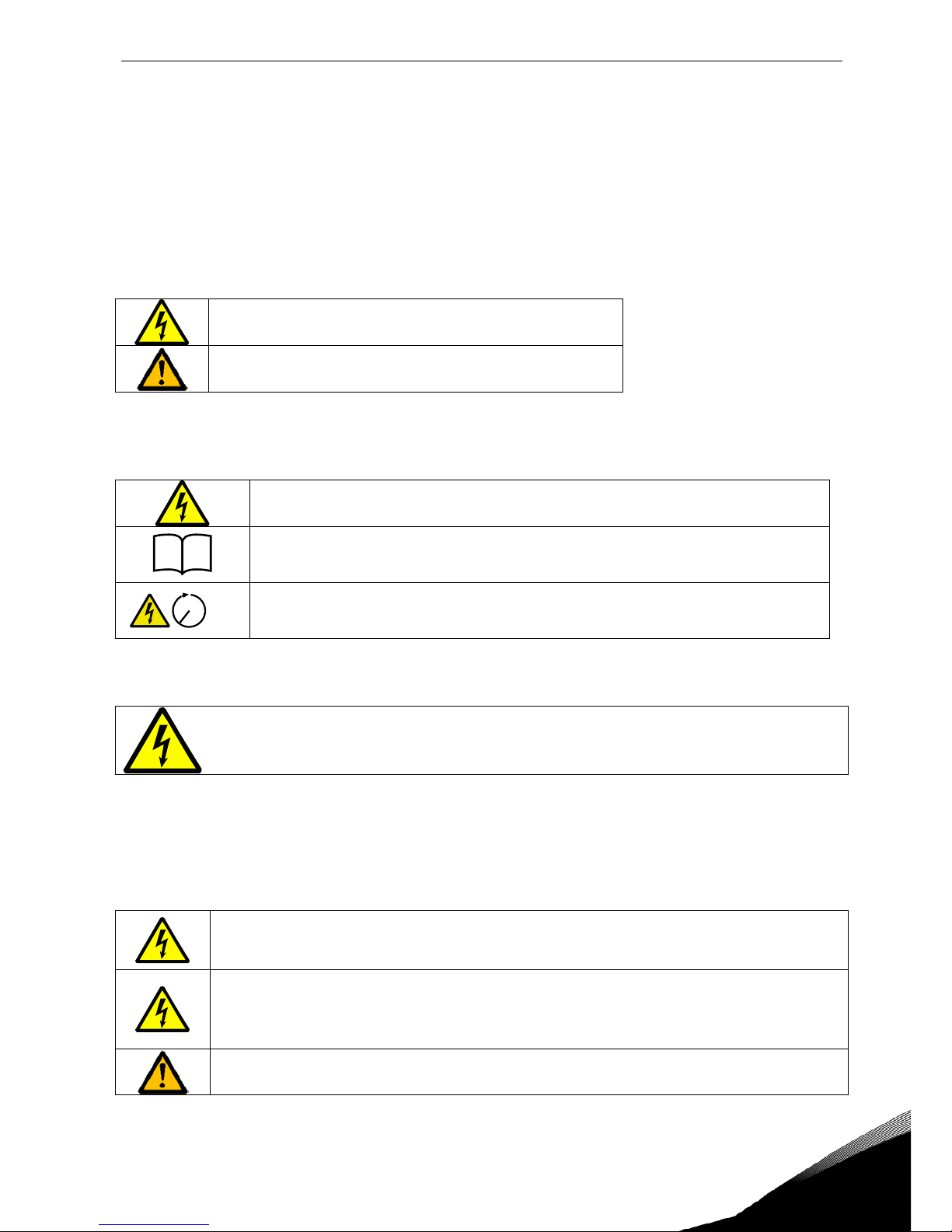
1.1 Danger and warning symbols used in this manual
This manual contains clearly marked cautions and warnings which are intended for your personal
safety and to avoid any unintentional damage to the product or connected appliances.
Please read the information included in cautions and warnings carefully.
The cautions and warnings are marked as follows:
=
Dangerous voltage! Risk of electric shock
=
General warning! Risk of equipment damage
1.2 Symbols and warning marks used in the product
The product carries some additional symbols and marks. The meanings of these are as follows:
=
Dangerous voltage! Risk of electric shock
i
= See User’s Manual
5
min
= Caution! Risk of electric shock! Energy storage timed discharge:
5 minutes
1.3 Safety rules
ONLY A COMPETENT ELECTRICIAN IS ALLOWED TO CARRY OUT THE ELECTRICAL INSTALLATION! RISK OF ELECTRIC SHOCK!
The solar inverter VACON 8000 SOLAR has been designed to be installed in enclosed places. It shall
be protected against harsh weather conditions.
The solar inverter VACON 8000 SOLAR can only be opened by qualified technicians. Inside the inverter module, there is no element which can be fixed or adjusted by the user.
There is a serious risk of electric shock, even after the device has been disconnected
from the mains supply or
solar panels. This electric shock may cause death or serious
injury.
If the short circuit current of the grid is higher than the short circuit withstanding capability of the QA2, additional circuit breaker must be installed. If the possible short
circuit current at the grid point of connection is higher than the solar inverter’s breaking capacity, additional current limiting device must be installed (see chapter 5.4).
If the equipment is used in a manner not specified by the manufacturer, the protection
provided by the equipment may be impaired.
Page 4
4 • vacon
Tel: +358-201-2121 • Fax: +358-201-212 205
Even when the solar inverter has been disconnected from mains and solar panels, wait until the control panel switches off. After this, it is recommended that you wait at least 5 minutes before opening,
and /or making any kind of alteration or connection to, the device.
Check that there is no voltage present before handling and performing any kind of work on the device. To verify the absence of voltage, type III measurement elements (1000 volts) must be used.
Do not perform any measurement or test when the VACON 8000 SOLAR is connected to mains or solar panels.
Do not perform any kind of dielectric strength test on the VACON 8000 SOLAR. Unless the appropriate process is followed, performing this test may damage the inverter module.
Appropriate personal protective equipment (PPEs) must be used:
Helmet
Safety goggles for electrical risk
Safety footwear
Electrically resistant gloves adequate for the voltage
Protective gloves against mechanical risk
Access to the photo-voltaic field is strictly prohibited!
1.4 Earthing and earth fault protection
CAUTION!
The Vacon 8000 Solar inverter must always be earthed with an earthing conductor connected to the
earthing terminal marked with
.
The touch current of Vacon 8000 Solar exceeds 3.5mA AC. According to EN62109-1, one or more of
the following conditions for the associated protective circuit shall be satisfied:
A fixed connection and
a) the
protective earthing conductor
shall have a cross-sectional area of at least 10 mm2 Cu or
16 mm
2
Al.
or
b) an automatic disconnection of the supply in case of discontinuity of the
protective earthing
conductor
. See chapter 4.
or
c) provision of an additional terminal for a second
protective earthing conductor
of the same
cross-sectional area as the original
protective earthing conductor
.
Page 5
vacon • 5
24-hour support: +358 (0)201 212 575 • Email: vacon@vacon.com
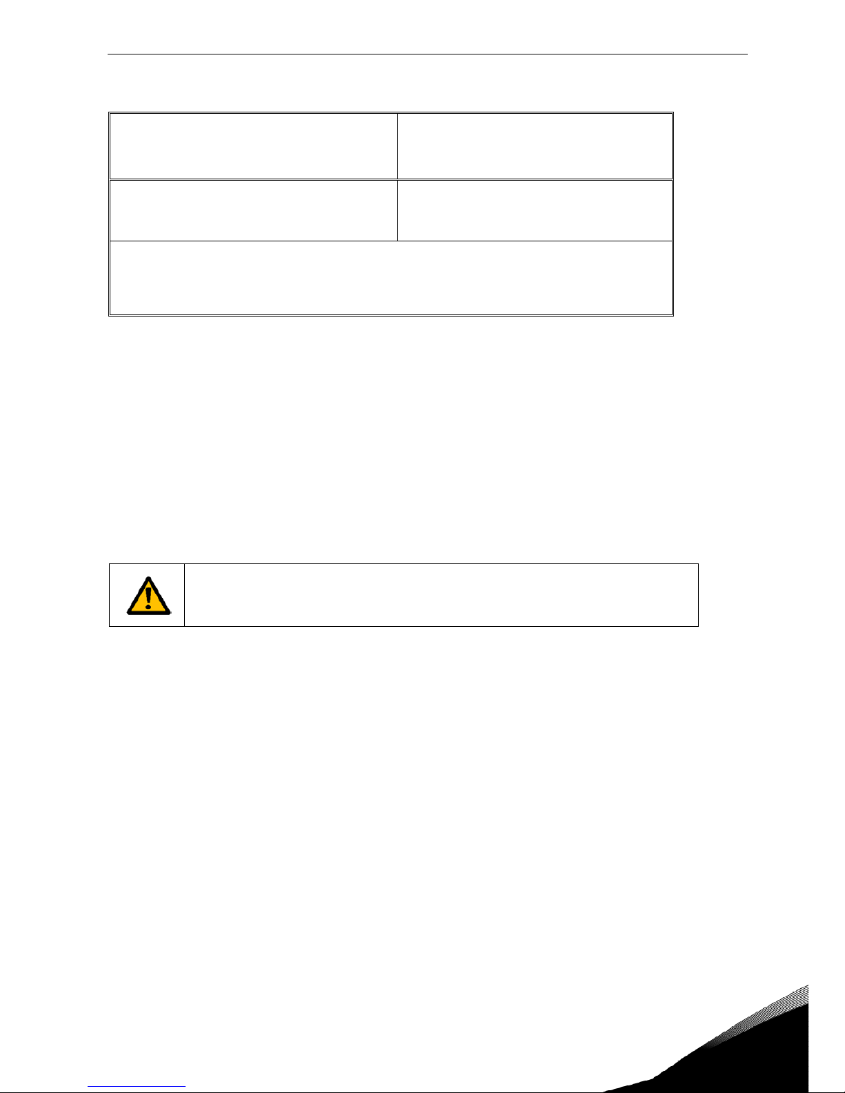
Cross-sectional area of phase conductors
(S)
[mm2]
Minimum cross-sectional area of the cor-
responding
protective earthing conductor
[mm2]
S ≤ 16
16 <
S ≤ 35
35 <
S
S
16
S/2
The values above are valid only if the protective earthing conductor is made of the same metal as
the phase conductors. If this is not so, the cross-sectional area of the protective earthing conductor shall be determined in a manner which produces a conductance equivalent to that which
results from the application of this table.
The cross-sectional area of every protective earthing conductor which does not form a part of the
supply cable or cable enclosure shall, in any case, be not less than
• 2.5 mm
2
if mechanical protection is provided or
• 4 mm
2
if mechanical protection is not provided. For cord-connected equipment, provisions
shall be made so that the protective earthing conductor in the cord shall, in the case of failure
of the strain-relief mechanism, be the last conductor to be interrupted.
However, always follow the local regulations for the minimum size of the protective earthing conductor.
NOTE: Due to the high capacitive currents present in the AC drive, fault current protective switches
may not function properly.
Do not perform any voltage withstand tests
on any part of Vacon 8000 Solar.
There is a certain procedure according to which the tests shall be performed.
Ignoring this procedure may result in damaged product.
Page 6

6 • vacon TECHNICAL SPECIFICATIONS
Tel: +358-201-2121 • Fax: +358-201-212 205
2. TECHNICAL SPECIFICATIONS
2.1 Inverter ratings
Range of input voltages 340-800Vcc, 50 Hz, 3~
Inverter
type
Nom. output
power
[kW]
Recommended
max PV power
[kW]
Max al-
lowed PV
power
[A]
Max effi-
ciency [%]
Power con-
sumption at
night
[W]
Inverter
dimensions
[mm]
Inverter
weight
[kg]
NXV0010 10 12 50 >94% <5 600x1481x600 220
NXV0015 15 18.5 50 >94%
<5 600x1481x600 220
NXV0020 20 24 99 >94%
<5 600x1481x600 300
NXV0025 25 30 99 >94%
<5 600x1481x600 300
NXV0030 30 36 99 >94%
<5 600x1481x600 300
NXV0040 40 48 198 >95% <30 800x1881x600 550
NXV0050 50 60 198 >96%
<30 800x1881x600 550
NXV0080 80 96 353 >96%
<30 800x2281x600 850
NXV0100 100 120 353 >96%
<30 800x2281x600 850
Table 2-1. Power ratings, dimensions and weights
2.2 Technical data
DC Input
Range of input voltages 340...800 VDC
Maximum input voltage 900 VDC
AC Output
Mains voltage 3*400 ± 10%
Galvanic isolation For each isolator transformer attached
Frequency 50/60 Hz ± 0,5%
Cos
φ
>0.99, for output 20%-100% of Pn
Harmonic distortion < 2.5% for output > 30% of power
Consumption at night < 5W (NXV0010...NXV0030); <30 W (NXV0040...NXV0100)
Maximum efficiency > 94...96%
Ambient temperature -10...+40°C; 1-% derating for each degree up to 50°C required
Relative humidity
< 95% no condensation
Protection IP21
Display
Alfanumeric display per unit with two lines of 14 characters, leds
indicating functioning, plus fault and function push buttons.
Signalling 3 potential free contacts to indicate faults and alarms
Communications May include one of the following communication buses as an op-
tional feature: Modbus RTU, Ethernet (Modbus/TCP), RS485, GPRS,
string and inverter monitoring
May include a monitoring system with http-access as an optional
feature.
IEC61000-3-3 For the product to meet the technical requirements of IEC 61000-3-
3, the supply should have a system impedance accordingly:
≤ NXV0015: Zsys = 0.105 ohm
≤ NXV0030: Zsys = 0.270 ohm
≤ NXV0050: Zsys = 0.176 ohm
≤ NXV0100: Zsys = 0.136 ohm
Ambient conditions
Altitude Max. 2,000m
Environmental category Indoor, conditioned
Pollution degree PD2
Overvoltage
category
AC (Mains) OVCIII
DC (Panels) OVCII
Table 2-2. Technical data
Page 7
RECEIPT OF DELIVERY vacon • 7
24-hour support: +358 (0)201 212 575 • Email: vacon@vacon.com
3. RECEIPT OF DELIVERY
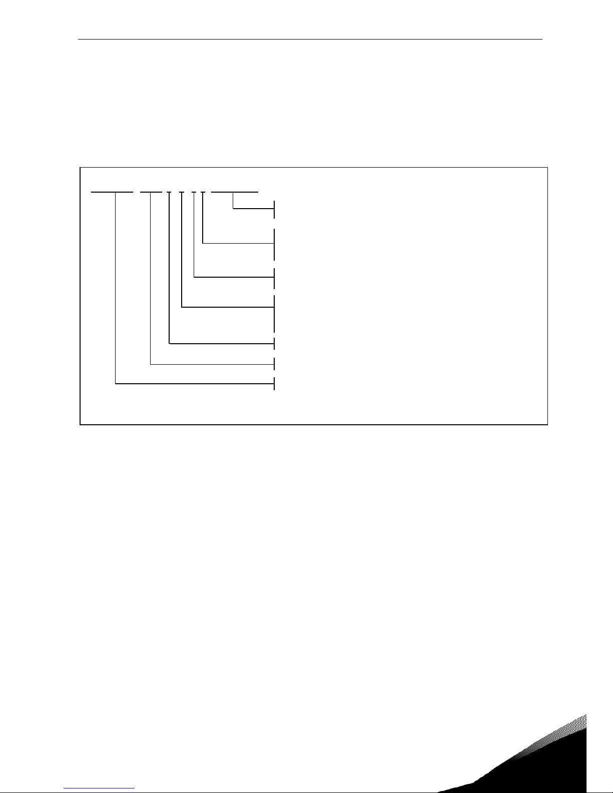
3.1 Type designation code
Vacon 8000 Solar inverters have undergone scrupulous tests and quality checks at the factory before
they are delivered to the customer. However, after unpacking the product, check that no signs of
transport damages are to be found on the product and that the delivery is complete (compare the
type designation of the product to the code below).
VACON NXV 0010 4 A 2 L A1A2 D700XX
nk3_1b_solar.ai
Vacon NXV = Solar power inverter
Nominal power
0010 = 10 kW, 0100 = 100 kW etc.
4 = Galvanic isolation transformer, ouptut 3 x 400 VAC
Control keypad and display on the cabinet door:
A = standard (alpha-numeric)
B = no local control keypad
F = dummy keypad
G = graphic display
Enclosure class:
2 = IP21/NEMA 1
EMC emission level:
L = fulfils requirements of category C3 of standard EN61800-3 (2004),
2nd environment and rated voltage less than 1000V
T = fulfils standard EN61800-3 (2004) when used in IT networks
Option boards; each slot is represented by two characters where:
A = basic I/O board, B = expander I/O board,
C = fieldbus board, D = special board, 00 = Not used
Figure 3-1. Type designation code
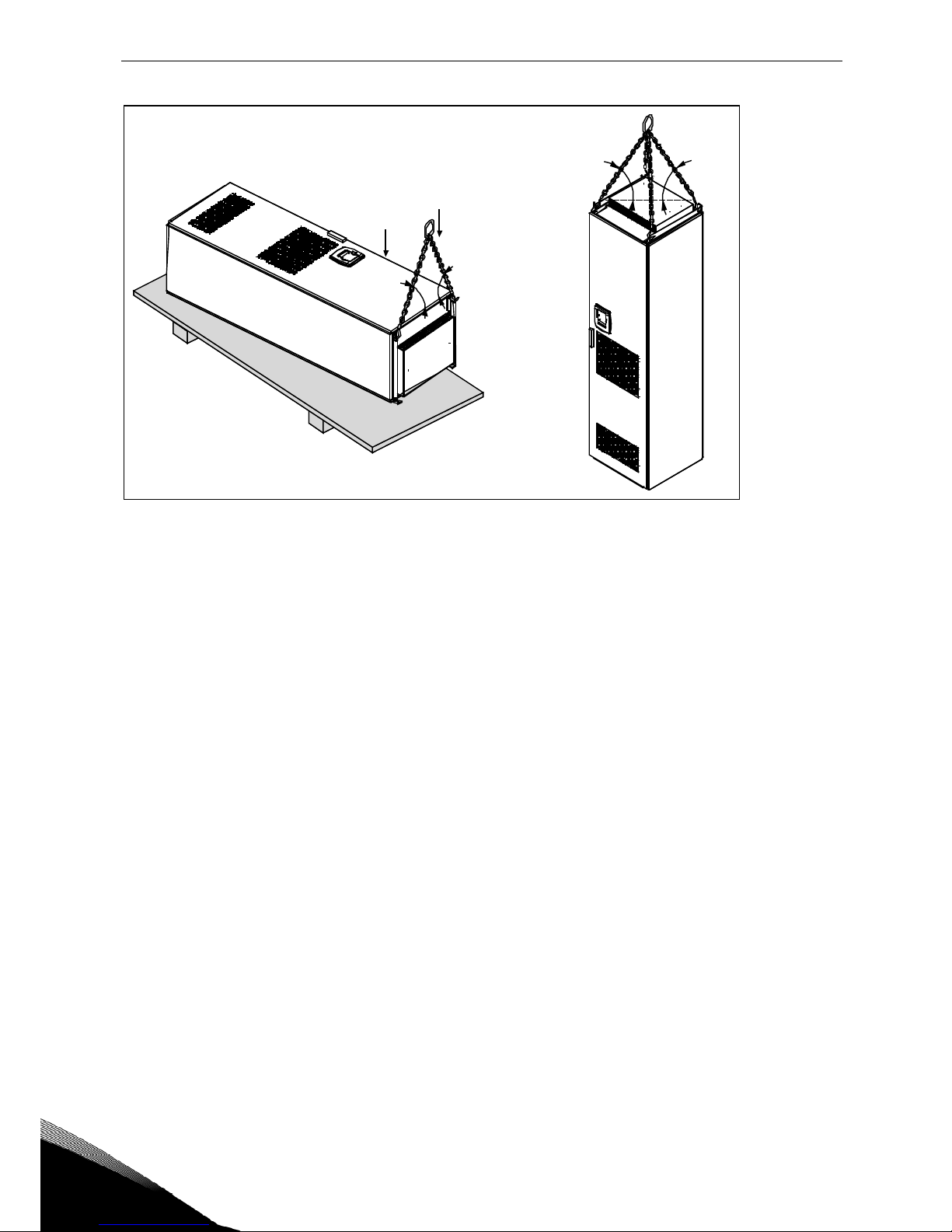
3.2 Lifting the unit out of the transport packaging
Before unpacking the device, check the correctness of delivery by comparing your order data to the
drive information found on the package label.
The unit is delivered either in a wooden box or a wooden cage. The box may be transported either
horizontally or vertically, while transportation of the cage in a horizontal position is not allowed. Always refer to shipping marks for more detailed information. To lift the unit out of the box, use lifting
equipment capable of handling the weight of the cabinet.
There are lifting lugs on the top of the cabinet and these lugs can be used to lift the cabinet into an
upright position and to move it to the place needed.
Units NXV 0010 and NXV0100 may be lifted as shown in Figure 3-2, in vertical or horizontal position.
Page 8
8 • vacon RECEIPT OF DELIVERY
Tel: +358-201-2121 • Fax: +358-201-212 205
Min 60°
Min 60°
Min 60°
Figure 3-2. Lifting unit cabinet
After unpacking the product, check that no signs of transport damages are to be found on the product and that the delivery is complete.
If the delivery does not correspond to your order, contact the supplier immediately.
Should the drive have been damaged during the shipping, please contact primarily the cargo insurance company or the carrier.
If the equipment has been damaged, do not install it.
Keep the original packaging in case it is necessary to return the equipment to the manufacturer.
Otherwise recycle the packaging material according to local regulations.
3.3 Storage
If the inverter is to be kept in store before use make sure that the ambient conditions are acceptable:
Storing temperature –40…+70
°C
Relative humidity <95%, no condensation
The environment should also be free from dust. If there is dust in the air the inverter should be well
protected to make sure dust does not get inside it.
If the inverter is to be stored during longer periods the power should be connected to the inverter
once in 24 months and kept on for at least 2 hours. If the storage time exceeds 24 months the electrolytic DC capacitors need to be charged with caution. Therefore, such a long storage time is not
recommended.
If the storing time is much longer than 24 months, the recharging of the capacitors has to be carried
out so that the possible high leakage current through the capacitors is limited. The best alternative
is to use a DC-power supply with adjustable current limit. The current limit has to be set for example
Page 9
RECEIPT OF DELIVERY vacon • 9
24-hour support: +358 (0)201 212 575 • Email: vacon@vacon.com
to 300…500mA and the DC-power supply has to be connected to the B+/B- terminals (DC supply
terminals).
DC-voltage must be adjusted to nominal DC-voltage level of the unit (1.35*Un AC) and supplied at
least for 1 hour.
If DC-voltage is not available and the unit has been stored de-energized much longer than 1 year
consult factory before connecting power.
3.4 Maintenance
In normal conditions, Vacon NX 8000 Solar inverters are maintenance-free. However, we recommend to keep the inverter clean, e.g. by cleaning the heatsink with compressed air whenever necessary.
We also recommend to follow proactive maintenance schedule below to ensure the highest possible
utilization rate of the cabinet drive.
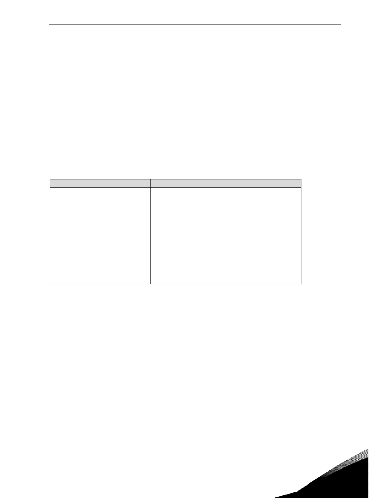
Maintenance interval Maintenance action
12 months (if unit stored)
• Reform capacitors (see separate instruction)
6-24 months
(depending on environment)
• Check I/O terminals
• Check tightness of mains connection (e.g. with
thermography)
• Clean cooling tunnel
• Check operation of cooling fan, check for cor-
rosion on terminals, busbars and other surfaces
5-7 years
• Change cooling fans:
- main fan
-
fan of the LCL filter
5-10 years
• Change DC bus capacitors if DC voltage ripple
is high
Table 3-1. Proactive maintenance schedule
3.5 Warranty
Only manufacturing defects are covered by the warranty. The manufacturer assumes no responsibility for damages caused during or resulting from transport, receipt of the delivery, installation, commissioning or use.
The manufacturer shall in no event and under no circumstances be held responsible for damages
and failures resulting from misuse, wrong installation, unacceptable ambient temperature, dust,
corrosive substances or operation outside the rated specifications.
Neither can the manufacturer be held responsible for consequential damages.
The Manufacturer's standard time of warranty is 18 months from the delivery or 12 months from the
commissioning whichever expires first (Vacon Warranty Terms).
The local distributor may grant a warranty time different from the above. This warranty time shall be
specified in the distributor's sales and warranty terms. Vacon assumes no responsibility for any other warranties than that granted by Vacon itself.
In all matters concerning the warranty, please contact first your distributor.
Page 10
10 • vacon INSTALLATION
Tel: +358-201-2121 • Fax: +358-201-212 205
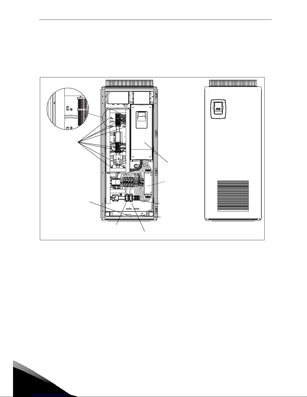
4. INSTALLATION
The installation of the VACON 8000 SOLAR solar inverter may only be carried out by a qualified technician who fully understands the safety and installation instructions included in this manual.
The IP21 protection of the VACON 8000 SOLAR inverter only allows for installation in enclosed places.
Note the locations of some essential components of the inverters in pictures below:
PE terminals
(8 pcs)
Opening for
cables
DC+ terminals
DC- terminals
PE busbar
L1, L2, L3
Control unit
RFI filter
Figure 4-1. Pricipal drawing of inverter modules NXV0010 to NXV0030 with some essential components
Page 11
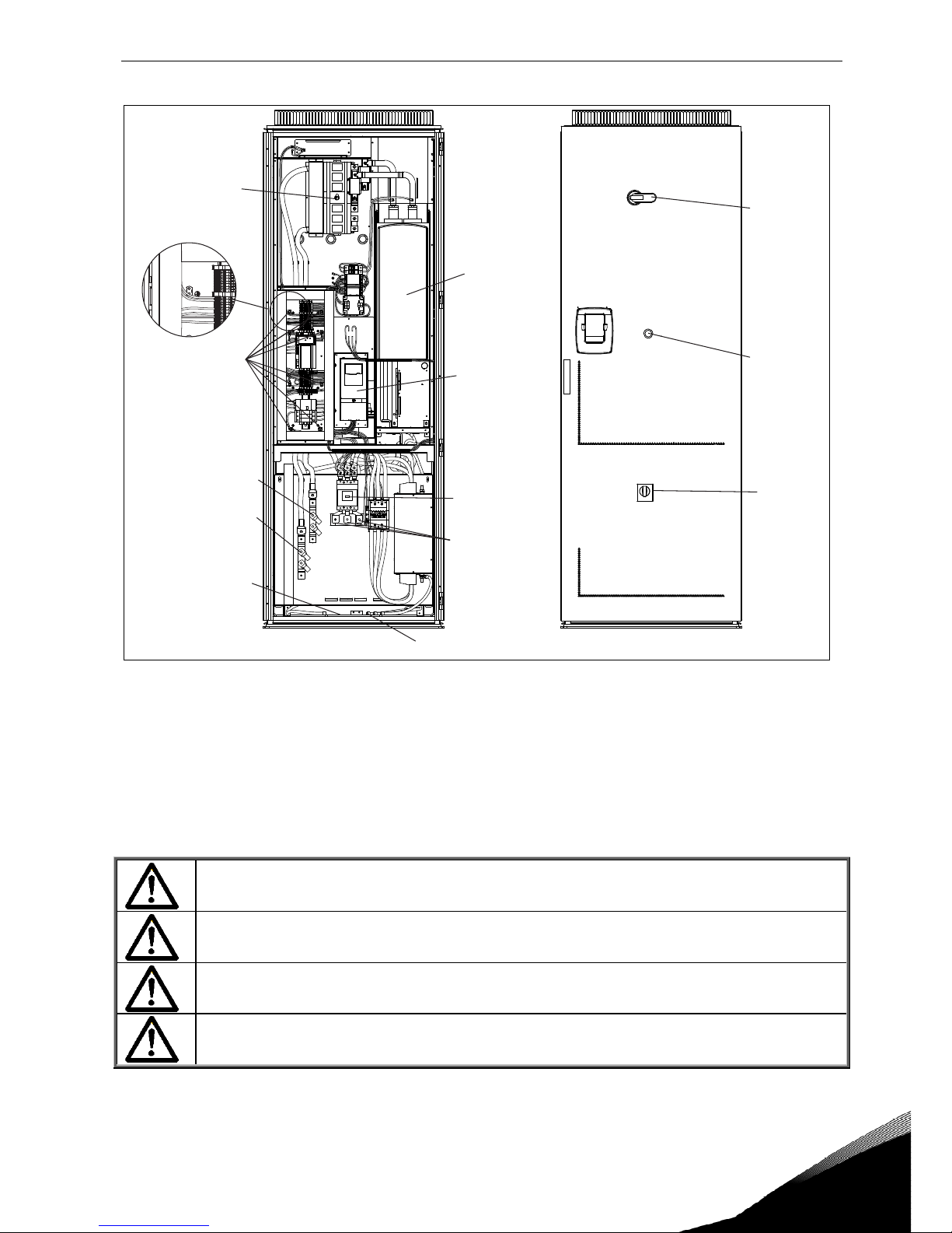
INSTALLATION vacon • 11
24-hour support: +358 (0)201 212 575 • Email: vacon@vacon.com
DC switch
DC switch
DC- terminals
DC+ terminals
PE busbar
AC switch
AFE unit
Control
unit
L1, L2, L3
Opening for
cables
PE terminals
(8 pcs)
AC switch
Emergency
stop
Figure 4-2. Pricipal drawing of inverter modules NXV0040 and NXV0100 with some essential components
Due to the heavy weight of the device, it must be placed on a firm and horizontal surface.
The equipment has to be installed in a place where the room temperature is between -10ºC and
+40ºC. Lower temperatures prevent the equipment from starting up and higher temperatures limit
the output power.
The buzzing noise occurring during the operation of the equipment is normal. Do not install the
equipment in an occupied dwelling.
NOTE:
It is important to prevent small particles falling onto the device. Small particles
may enter the equipment through the ventilation grids and damage the equipment.
Do not block the ventilation grids.
Unit must be installed on non-flammable ground.
The unit is not intended for wet location.
Page 12
12 • vacon INSTALLATION
Tel: +358-201-2121 • Fax: +358-201-212 205
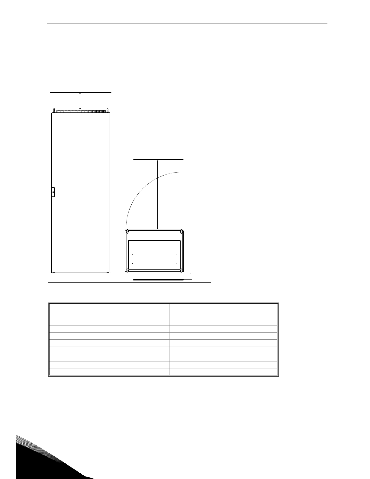
4.1 Free space around the cabinet
Enough space must be left above, behind and in front of the cabinet to ensure sufficient cooling and
space for maintenance.
The amount of cooling air required is indicated in the table below. Also make sure that the temperature of the cooling air does not exceed the maximum ambient temperature of the inverter.
200 mm
800 mm
25 mm
Figure 4-3. Space to be left free above (left) and in front of (right) the cabinet.
Type
Cooling air required
[m3/h)
NXV0010
300
NXV0015
300
NXV0020
425
NXV0025
425
NXV0030
425
NXV0040
700
NXV0050
700
NXV0080
800
NXV0100
800
Table 4-1. Required cooling air
Page 13
INSTALLATION vacon • 13
24-hour support: +358 (0)201 212 575 • Email: vacon@vacon.com
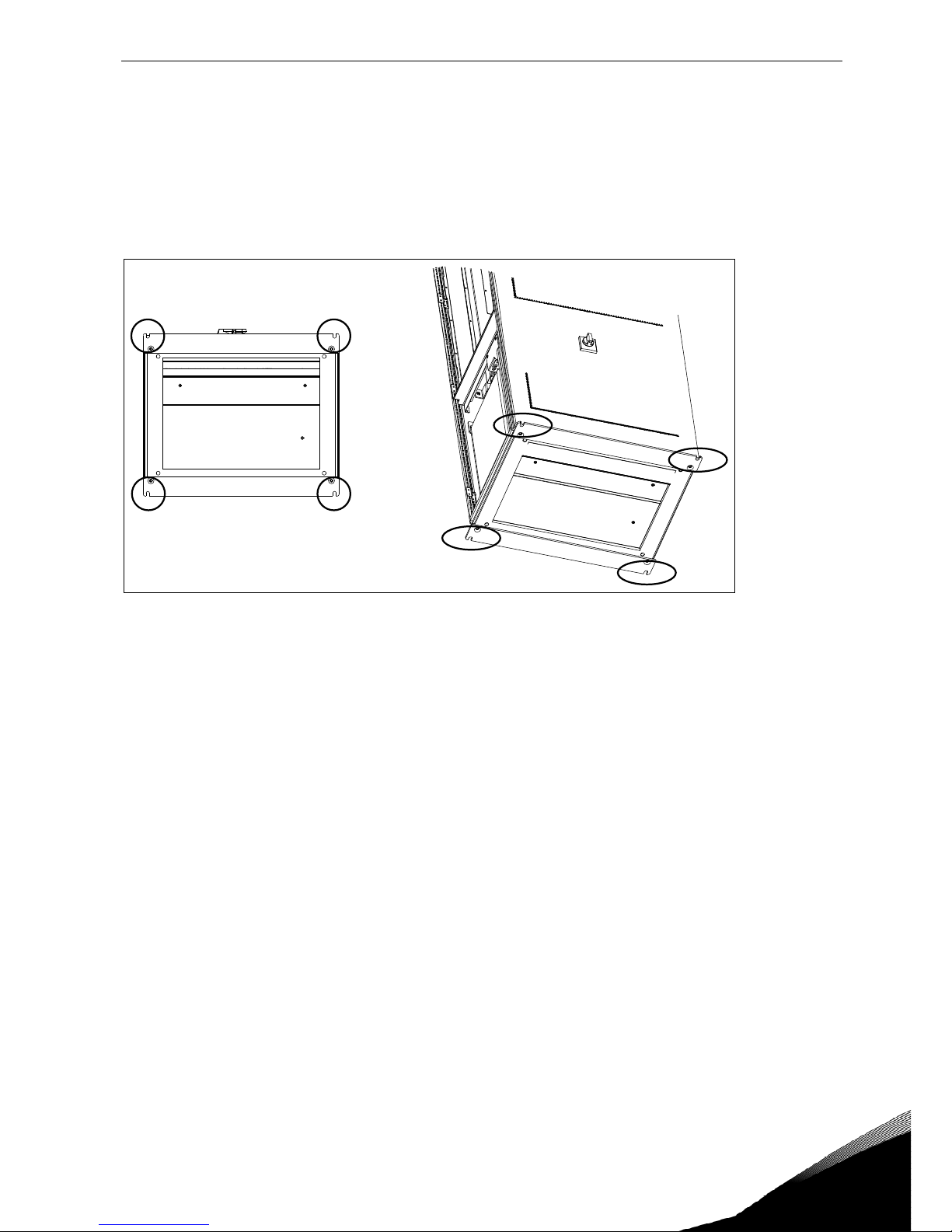
4.2 Fixing the unit
The cabinet can be fixed to the floor alone or to the floor and the back wall.
4.2.1
Fixing the unit to floor alone
For the floor-only-mounting, the fixing points in all four bottom corners of the cabinet shown in Figure 4-4 below must be used.
BOTTOM VIEW
FRONT
REAR
Figure 4-4. Fixing the cabinet to the floor only
Page 14
14 • vacon INSTALLATION
Tel: +358-201-2121 • Fax: +358-201-212 205
4.2.2
Fixing the unit to floor and wall
For additional stability, the cabinet can also be mounted to the floor and the back wall. To accomplish this, follow this procedure:
1. On the bottom of the cabinet, remove the screws of the rear iron clamp. Flip it and refix the
screws as shown in
Figure 4-5.
2. Then bolt the cabinet to the floor at the fixing points on the bottom front side, see Figure 4-5.
BOTTOM VIEW
FRONT
REAR
Rear iron clamp
Figure 4-5.
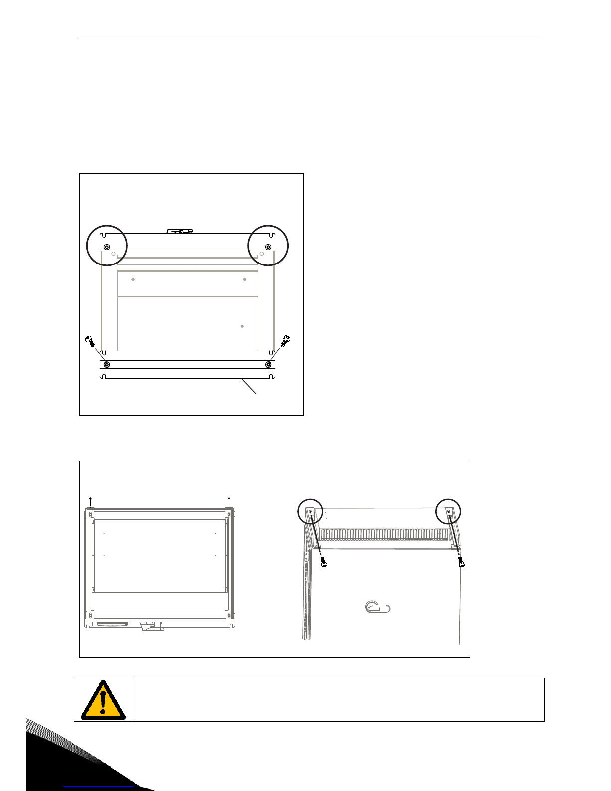
3. Use the fixing points at the top rear side of the cabinet to bolt it to the back wall. See Figure 4-6.
TOP VIEW
REAR
FRONT/TOP VIEW
FRONT
Figure 4-6.
Welding of the cabinet might risk sensitive components in the converter.
Ensure that no grounding currents can flow through any part of the converter.
Page 15

ELECTRICAL CONNECTION vacon • 15
24-hour support: +358 (0)201 212 575 • Email: vacon@vacon.com
5. ELECTRICAL CONNECTION
Only a competent electrician is allowed to install the electrical connection. The
equipment uses dangerous voltages.
There is danger of electrical shock which may cause death or serious injury.
5.1 Electrical diagrams
5.1.1
NXV0010 to NXV0030
R<
-BE1
-RF5
340...800VDC, 30A 3Ph 400V 50Hz, 22A
-QA1
4
-TB2
3
2
3
-RA1
3
-CA1
-QA5
-QA2
3
-FC4
3
-FA1
3
-PE1
-FCP
2
-TA0
3+PE
3
-PE1
+01
Figure 5-1. Electrical diagram for NXV0010 to NXV0030
5.1.2
NXV0040 to NXV0050
R<
-BE1
-RF5
340...800VDC, 100A 3Ph 400V 50Hz, 72A
-TB2
3
2
3
-RA1
3
-CA1
-QA5
-FC4
3
-FA1
3
-PE1-FCP
2
-TA0
3+PE
3
-PE1
+01
-QB1 -FC3
2
-QA2
3
I>
Figure 5-2. Electrical diagram for NXV0040 to NXV0050
Page 16

16 • vacon ELECTRICAL CONNECTION
Tel: +358-201-2121 • Fax: +358-201-212 205
5.1.3
NXV0080 to NXV0100
R<
-BE1
-RF5
340...800VDC, 200A 3Ph 400V 50Hz, 145A
-TB2
3
2
3
-RA1.1
3
-CA1
-QA5
-FC4
3
-FA1
3
-PE1
-FCP
2
-TA0
3+PE
3
-PE1
+01
-QB1
-FC3
2
-RA1.2
3
-QA2
3
I>
Figure 5-3. Electrical diagram for NXV0080 to NXV0100
Page 17

ELECTRICAL CONNECTION vacon • 17
24-hour support: +358 (0)201 212 575 • Email: vacon@vacon.com
5.2 Cabling
Before connecting the cables to the solar inverter, use a multimeter to check that the cables to be
connected are not live.
Cables coming from photovoltaic panels will be active while panels are lit.
5.2.1
Earth connection
The solar inverter has an earth connection terminal to which all the inverter's metallic parts are
connected. This connection terminal must be connected to earth. Remember to earth the PE busbar.
See Table 5-1 on page 18.
5.2.2
Connection to mains
The terminals of the power supply can be reached through the bottom part of the equipment. The
solar inverter has three connection terminals, to which mains cables are connected.
Run the cables through the opening on the bottom of the cabinet. See Figure 5-5.
PE busbar
L1
L2
L3
DC+
DC-
Opening for
cables
Figure 5-4. Mains cabling NXV0015 to NXV0030 (cable clamps not included in delivery)
Page 18

18 • vacon ELECTRICAL CONNECTION
Tel: +358-201-2121 • Fax: +358-201-212 205
PE busbar
L1 L2 L3
DCDC+
Opening for
cables
Figure 5-5. Mains cabling NXV0040 and NXV0100 unit (cable clamps not included in delivery)
The cable cross section will be determined according to the power and distance to the connection
point, following the local regulations.
Size
Minimum cross section
per unit [mm2]
Maximum cross section
per unit [mm2]
AC
DC
PE
AC
DC
PE
NXV0010 1,5 6 10 50 95 240
NXV0015 1,5 6 10 50 95 240
NXV0020 1,5 6 10 50 95 240
NXV0025 1,5 6 10 50 95 240
NXV0030 1,5 6 10 50 95 240
NXV0040 10 10 10 240 240 240
NXV0050 10 10 10 240 240 240
NXV0080 10 10 10 240 240 240
NXV0100
10
10
10
240
240
240
Table 5-1.Minimum and maximum cable cross sections
The tightening torques of power connections are given in tables below:
Drive size
Terminal size
[mm2]
Screw/Bolt size
Tightening torque
[Nm]
NXV0010...NXV0030
1,5...2,5
1,5
4...10 5
16...50 12
NXV0040...NXV0100
M6 8...10
M8 18...22
M10 35...45
M12 65...75
Table 5-2. Tightening torques of power connections
Page 19

ELECTRICAL CONNECTION vacon • 19
24-hour support: +358 (0)201 212 575 • Email: vacon@vacon.com
5.2.3
Connection to photovoltaic panels
Remember
that photovoltaic panels produce a current while they are illuminated. Be
sure to check that cables are not live.
NOTE!
Wrongly connected cables may damage the equipment.
Run the solar panel cables to the respective terminals on the drive through the bottom of the supply
unit (see Figure 5-5 and Figure 5-6). Check for the cable sizes and the appropriate number of cables
in tables on page 20.
In drives NXV0050 and NXV0100, always connect the two cables on both sides of the terminal bar
(see Figure 5-6).
Connect the positive pole of the photovoltaic panel to the terminal marked with ‘+’ and the negative
pole to the terminal marked with ‘-‘.
PE busbar
L1
L2
L3
DC+
DC-
Opening for
cables
Figure 5-6. Inverter connection to solar panels, NXV0015 to NXV0030
Page 20

20 • vacon ELECTRICAL CONNECTION
Tel: +358-201-2121 • Fax: +358-201-212 205
PE busbar
L1 L2 L3
DCDC+
Opening for
cables
Figure 5-7. Inverter connection to solar panels, NXV0040 to NXV0100
Model
Minimum cross section
Recommended cross section
Maximum cross section
NXV0010 2x6mm
2
2x50mm
2
2x 2x95mm
2
NXV0015 2x16mm
2
2x70mm
2
2x 2x95mm
2
NXV0020 2x25mm
2
2x95mm
2
2x 2x95mm
2
NXV0025 2x35mm
2
2x95mm
2
2x 2x95mm
2
NXV0030 2x35mm
2
2x 2x70mm
2
2x 2x95mm
2
NXV0040 2x70mm
2
2x 2x95mm
2
4x 2x185mm
2
NXV0050 2x95mm
2
2x 2x95mm
2
4x 2x185mm
2
NXV0080 2x 2x70mm
2
4x 2x95mm
2
4x 2x185mm
2
NXV0100 2x 2x95mm
2
4x 2x95mm
2
4x 2x185mm
2
Table 5-3. Panel input cable dimensions
Model
Minimum cross section
Recommended cross section
Maximum cross section
NXV0010 3x1,5mm
2
3x16mm
2
3x50mm
2
NXV0015 3x1,5mm
2
3x25mm
2
3x50mm
2
NXV0020 3x1,5mm
2
3x25mm
2
3x50mm
2
NXV0025 3x1,5mm
2
3x35mm
2
3x50mm
2
NXV0030 3x1,5mm
2
3x50mm
2
3x50mm
2
NXV0040 3x16mm
2
3x50mm
2
3x120mm
2
NXV0050 3x25mm
2
3x70mm
2
3x120mm
2
NXV0080
3x50mm
2
3x95mm
2
3x120mm
2
NXV0100 3x70mm
2
3x120mm
2
3x120mm
2
Table 5-4. Panel output cable dimensions
Page 21

ELECTRICAL CONNECTION vacon • 21
24-hour support: +358 (0)201 212 575 • Email: vacon@vacon.com
Model
Cross section
NXV0010 10mm
2
NXV0015 10mm
2
NXV0020 16mm
2
NXV0025 16mm
2
NXV0030 16mm
2
NXV0040 25mm
2
NXV0050 25mm
2
NXV0080 35mm
2
NXV0100 35mm
2
Table 5-5 Panel earthing cable dimensions
The minimum cable cross section is calculated in compliance with loading capacity of cables. The
recommended cross section is calculated in compliance with 1-% voltage drop for a cable 100 m in
length.
Page 22

22 • vacon ELECTRICAL CONNECTION
Tel: +358-201-2121 • Fax: +358-201-212 205
5.3 Control connections
The control boards are situated inside the control unit of the Vacon 8000 Solar inverter (see Figure
5-8). Four different board types can be used with the inverter: A1, A2, B5, C2 and D7. The control
connections of these boards are described below. For more detailed information on the boards you
can find in Vacon Option Board Manual.
Figure 5-8. Board slots in control unit
Page 23

ELECTRICAL CONNECTION vacon • 23
24-hour support: +358 (0)201 212 575 • Email: vacon@vacon.com
5.3.1
Basic board OPTA1
Figure 5-9. Vacon OPT-A1 option board
Description:
Standard I/O board with digital inputs/outputs and analogue inputs/outputs
Allowed slots:
A
Type ID:
16689
Terminals:
Two terminal blocks (coded = mounting of blocks in wrong order prevented,
terminals #1 and #12);
Screw terminals (M2.6)
Jumpers:
4; X1, X2, X3 and X6 (See
Figure 5-10
.)
Board parameters:
Yes (see page 26)
Page 24

24 • vacon ELECTRICAL CONNECTION
Tel: +358-201-2121 • Fax: +358-201-212 205
I/O terminals on OPTA1 (coded terminals painted black)
Terminal
Parameter reference
on keypad and NCDrive
Technical information
1
+10 Vref
Reference output +10V; Maximum current 10 mA
2
AI1+ An.IN:
A.1
Selection V or mA with jumper block X1 (see page 25):
Default: 0– +10V (Ri = 200 kΩ)
(-10V..+10V Joy-stick control, selected with ajumper)
0– 20mA (Ri = 250 Ω)
Resolution 0.1%; Accuracy ±1%
3
AI1– Differential input if not connected to ground;
Allows ±20V differential mode voltage to GND
4
AI2+ An.IN:
A.2
Selection V or mA with jumper block X2 (see page 25):
Default: 0– 20mA (Ri = 250 Ω)
0– +10V (Ri = 200 kΩ)
(-10V..+10V Joy-stick control, selected with a jumper)
Resolution: 0.1%; Accuracy ±1%
5
AI2– Differential input if not connected to ground;
Allows ±20V differential mode voltage to GND
6
24 Vout (bidirectional)
24V auxiliary voltage output. Short-circuit protected.
±15%, maximum current 150 mA
+24Vdc external supply may be connected.
Galvanically connected to terminal #12.
7
GND
Ground for reference and controls
Galvanically connected to terminals #13,19.
8
DIN1 DigIN:
A.1
Digital input 1 (Common CMA); Ri = min. 5kΩ
9
DIN2 DigIN:
A.2
Digital input 2 (Common CMA); Ri = min. 5kΩ
10
DIN3 DigIN:
A.3
Digital input 3 (Common CMA); Ri = min. 5kΩ
11
CMA Digital input common A for DIN1, DIN2 and DIN3.
Connection by default to GND.
Selection with jumper block X3 (see page 25):
12
24 Vout (bi-
directional)
Same as terminal #6
Galvanically connected to terminal #6.
13
GND Same as terminal #7
Galvanically connected to terminals #7 and 19
14
DIN4 DigIN:
A.4
Digital input 4 (Common CMB); Ri = min. 5kΩ
15
DIN5 DigIN:
A.5
Digital input 5 (Common CMB); Ri = min. 5kΩ
16
DIN6 DigIN:
A.6
Digital input 6 (Common CMB); Ri = min. 5kΩ
17
CMB Digital input common B for DIN4, DIN5 and DIN6.
Connection by default to GND.
Selection with jumper block X3 (see page 25):
18
AO1+ AnOUT:
A.1
Analogue output
Output signal range:
Current 0(4)–20mA, R
L
max 500Ω or
Voltage 0—10V, R
L
>1kΩ
Selection with jumper block X6 (see page 25):
Resolution: 0.1% (10 bits); Accuracy ±2%
19
AO1–
20
DO1 DigOUT:
A.1
Open collector output
Maximum U
in
= 48VDC
Maximum current = 50 mA
Table 5-6. OPTA1 I/O terminals
Page 25

ELECTRICAL CONNECTION vacon • 25
24-hour support: +358 (0)201 212 575 • Email: vacon@vacon.com
Jumper selections
There are four jumper blocks on the OPTA1 board. The factory defaults and other available jumper
selections are presented below.
Figure 5-10. Jumper block selection on OPTA1
A B C D
A B C D
A B C D
A B C D
A B C D
A B C D
A B C D
A B C D
A B C D
A B C D
Jumper block X1:
AI1 mode
AI1 mode: Voltage input; 0...10V
AI1 mode: Voltage input; 0...10V (differential)
AI1 mode: Voltage input; -10...10V
Jumper block X2:
AI2 mode
AI2 mode: 0...20mA; Current input
AI2 mode: Voltage input; 0...10V
AI2 mode: Voltage input; 0...10V (differential)
AI2 mode: Voltage input; -10...10V
Jumper block X3:
CMA and CMB grounding
CMB connected to GND
CMA connected to GND
CMB isolated from GND
CMA isolated from GND
CMB and CMA
internally connected together,
isolated from GND
= Factory default
Jumper block X6:
AO1 mode
AO1 mode: 0...20mA; Current output
AO1 mode: Voltage output; 0...10V
AI1 mode: 0...20mA; Current input
Page 26

26 • vacon ELECTRICAL CONNECTION
Tel: +358-201-2121 • Fax: +358-201-212 205
OPTA1 parameters
Number
Parameter
Min
Max
Default
Note
1 AI1 mode 1 5 3
1
= 0...20mA
2
= 4...20mA
3
= 0...10V
4
= 2...10V
5
= -10...+10V
2 AI2 mode 1 5 1
1
= 0...20mA
2
= 4...20mA
3
= 0...10V
4
= 2...10V
5
= -10...+10V
3 AO1 mode 1 4 1
1
= 0...20mA
2
= 4...20mA
3
= 0...10V
4
= 2...10V
Table 5-7. OPTA1 board-related parameters
Page 27

ELECTRICAL CONNECTION vacon • 27
24-hour support: +358 (0)201 212 575 • Email: vacon@vacon.com
5.3.2
Option board OPTA2
Description:
Standard Vacon NX frequency converter relay board with two relay outputs
Allowed slots:
B
Type ID:
16690
Terminals:
Two terminal blocks; Screw terminals (M3); No coding
Jumpers:
None
Board parameters:
None
I/O terminals on OPTA2
Terminal
Parameter reference
on keypad and NCDrive
Technical information
21
22
23
RO1/normal closed
RO1/common
RO1/normal open
DigOUT:
B.1
Relay output 1 (NO/NC)
Switching capacity 24VDC/8A
250VAC/8A
125VDC/0.4A
Min. switching load 5V/10mA
24
25
26
RO2/normal closed
RO2/common
RO2/normal open
DigOUT:
B.2
Relay output 2 (NO/NC)
Switching capacity 24VDC/8A
250VAC/8A
125VDC/0.4A
Min. switching load 5V/10mA
Table 5-8. OPTA2 I/O terminals
Page 28

28 • vacon ELECTRICAL CONNECTION
Tel: +358-201-2121 • Fax: +358-201-212 205
5.3.1
Option board OPTB5
Description:
I/O expander board with three relay outputs.
Allowed slots:
B, C, D, E
Type ID:
16949
Terminals:
Three terminal blocks; Screw terminals (M3); No coding
Jumpers:
None
Board parameters:
None
I/O terminals on OPTB5
Terminal
Parameter reference
Keypad/NCDrive
Technical information
22
23
RO1/common
RO1/normal open
DigOUT:
X.1
Switching capacity 24VDC/8A
250VAC/8A
125VDC/0.4A
Min. switching load 5V/10mA
25
26
RO2/common
RO2/normal open
DigOUT:
X.2
Switching capacity 24VDC/8A
250VAC/8A
125VDC/0.4A
Min. switching load 5V/10mA
28
29
RO3/common
RO3/normal open
DigOUT:
X.3
Switching capacity 24VDC/8A
250VAC/8A
125VDC/0.4A
Min. switching load 5V/10mA
Table 5-9. OPTB5 I/O terminals
Note: This expander board can be placed into four different slots on the control board. Therefore,
the '
X' given in the Parameter reference shall be replaced by the slot letter (B, C, D, or E) depending
on the slot which the expander board is plugged into.
Page 29

ELECTRICAL CONNECTION vacon • 29
24-hour support: +358 (0)201 212 575 • Email: vacon@vacon.com
5.4 Option board OPTC2 (RS-485)
Figure 5-11. Vacon RS-485 option board OPTC2
Signal
Connector
Description
NC* 1* No connection
VP 2 Supply voltage – plus (5V)
RxD/TxD –N 3 Receive/Transmit data – A
RxD/TxD –P 4 Receive/Transmit data – B
DGND 5 Data ground (reference potential for VP)
*You can use this pin (1) to bypass the cable shield to the next slave
Table 5-10. OPTC2 bus connector signals
X4
X1
Bus connector
Jumpers Interface board connector
Grounding plate
1
2
3
4
5
Page 30

30 • vacon ELECTRICAL CONNECTION
Tel: +358-201-2121 • Fax: +358-201-212 205
5.5 Option board OPTD7 (Line voltage measurement board)
OPTD7 is an AC sinusoidal voltage measurement board. Using this board, the drive measures the
line voltage, frequency and voltage angle information. The drive can compare this information with
its output voltage angle when running. This feature can be used to develop applications for different
purposes using NC61131-3 application programming tool.
The OPTD7 board is delivered with the transformer which is suitable for voltage range 380V …690V.
Please note that the transformer can not be used with the pulse width modulated (PWM) voltage input.
It is possible to use custom built transformer when the input voltage to be measured is not within
the above voltage range. The transformation ratio parameter then can be adjusted as per the transformer primary to secondary ratio. Please refer to specification section for further engineering.
The measurement signal connected into the OPT-D7 option board can not exceed 14.26 Vrms.
The board can only be placed in slot C.
OPTD7 connections
Figure 5-12.
Page 31

ELECTRICAL CONNECTION vacon • 31
24-hour support: +358 (0)201 212 575 • Email: vacon@vacon.com
OPTD7 board specification
Transformer primary/
input voltage range
Min 380VAC -15%
Max 690VAC +15%
Transformer ratio
Primary : secondary
60:1
Transformer secondary/output voltage range
14V rms Between the terminals L1/L2/L3.
Input impedence
L1/L2 =50kOhm
L1/L3 = 25kOhm
L2/L3 = 25kOhm
L3 is internal virtual common
Cable recommendation
Max 1.5 mm2, shielded From transformer output to OPTD7
Measurement resolution
10 bit
Voltage measurement
Accuracy
0.2%
Table 5-11. OPTD7 board specification
Page 32

32 • vacon ELECTRICAL CONNECTION
Tel: +358-201-2121 • Fax: +358-201-212 205
5.6 Fuse selection
The table below shows typical cable sizes and types that can be used with the Vacon 8000 Solar inverter. The final selection should be made according to local regulations, cable installation conditions and cable specification.
CAUTION!
Maximum AC-side short-circuit breaking capacity Icu=30kA.
With optional AC-section Icu=50kA.
5.6.1
Fuses for inverters
Inverter
type
Nominal
current
[A]
Nominal
voltage
[V]
Braking
capacity
[kA]
Acting
behaviour
Fuse size
Suitable fuse type
(Cat. nr by Ferraz-
Shawmut
NXV0010
No fuses needed
NXV0015
NXV0020
NXV0025
NXV0030
NXV0040 160 1200 100 gPV 121 DC121GPV12C160E
NXV0050 200 1200 100 gPV 121 DC121GPV12C200E
NXV0080 315 810 125 aR 71 DIN110 PC71UD13C315D1A
NXV0100 400 810 125 aR 71 DIN110 PC71UD13C400D1A
Table 5-12. Fuse selection; suitable fuses for Vacon 8000 Solar inverter types
5.6.2
Fuse for measuring
Nominal
current
[A]
Nominal
voltage
[V]
Braking
capacity
[kA]
Acting
behaviour
Fuse
size
Suitable fuse type (Cat.
nr by Ferraz-Shawmut
4 1000 10 gPV
10*38 HP10M4
Table 5-13. Fuse selection, fuse for measuring
Page 33

START UP vacon • 33
24-hour support: +358 (0)201 212 575 • Email: vacon@vacon.com
6. START UP
Starting up the VACON 8000 SOLAR inverter is simple, but it is important that the following instructions are followed:
1. Check that the cables from the solar panels are correctly connected and that the DC connec-
tion switch is connected.
2. Ensure that the cables coming from the mains supply, including the earth cable, are correct-
ly connected. Check that the main AC-circuit breaker and possible auxiliary circuit breakers
are connected and closed.
3. Press the START button on the control panel.
Once these steps have been followed, the inverter will automatically start when the voltage of solar
panels exceeds the minimum wake-up voltage, 340 V DC, provided that there is mains voltage.
The inverter starts up every day in the morning and automatically stops at night. Due to different atmospheric conditions, the inverter may start up and stop more than once each day.
Page 34

34 • vacon START UP
Tel: +358-201-2121 • Fax: +358-201-212 205
6.1 Inverter control keypad
The inverter has a control panel that displays its different variables and conditions.
6.1.1
Indicators of the inverter condition
Inverter state informs the user about conditions of the inverter and whether the control software has
detected any operating fault.
RUN = The inverter is running.
= Indicates the order of phases in the mains.
STOP =
Indicates that the inverter is not running.
READY = Illuminated when DC level is OK. In case of a fault, the symbol will not light up.
Also signifies a valid license or trial time.
ALARM = Indicates that the unit is running above a certain limit and issues an alarm.
FAULT = Indicates that there are unsafe running conditions and therefore the unit has
stopped.
5 6 2
3 1 4
READY
FAULT
STOP
RUN
Bus/Comm
Keypad
I/O term
ALARM
run
ready fault
1 2 3 4 5
6
a
b
c
•
•
•
••
•
I
II
III
Page 35

START UP vacon • 35
24-hour support: +358 (0)201 212 575 • Email: vacon@vacon.com
6.1.2
State leds
State LEDs light up according to state indicators READY, RUN and FAULT of the inverter. If all LEDs
blink the drive is uncommissioned.
= Lights up with DC voltage connected to the converter with no active failure. The state in-
dicator READY also lights up simultaneously.
= Lights up when the converter is running.
= Blinks when there are unsafe running conditions and the unit has therefore stopped
(fault trip). Simultaneously, the state indicator FAULT blinks in the display and shows a
description of the fault; see chapter Active Faults.
6.1.3
Text lines
The three text lines (•,••,•••) provide the user with information about the current location within the
menu structure of the panel, separate from information related to the operation of the unit.
• = Indication of the place in the panel; it shows the menu symbol and number, parameter,
etc.
Example: M1 = Menu 1 (Display); P1.3 = Generated power
•• = Description line; Shows the description of the menu, value or fault.
••• = Value line; it shows numeric values and reference texts, parameters, etc, as well as the
number of submenus available for each menu.
6.1.4
Panel push buttons
The alphanumeric control panel of the inverter VACON 8000 SOLAR has 9 push buttons used to control the inverter and to monitor values.
III
II
I
Page 36

36 • vacon START UP
Tel: +358-201-2121 • Fax: +358-201-212 205
6.1.4.1 Description of push buttons
reset = This push button is used to reset active faults.
select = This push button is used to switch between the two last displays.
enter = The Enter push button serves to:
Restore the fault history (2-3 seconds)
= Push button browser up
Browse the main menu and the pages of different submenus.
= Push button browser down
Browse the main menu and the pages of different submenus.
= Push button Menu left
Return to the menu.
= Push button Menu right
Go forward in the menu.
= To start the inverter
= To stop the inverter
6.1.5
Browsing the control panel
Data on the control panel is arranged in menus and submenus. Menus are used, for example, to display control signals and the measurements of reference values and faults shown
The first menu level has menus from M1 to M7 and it is called
Main menu
. The user can browse the
main menu using the Browse push buttons
up and down. The chosen submenu can be accessed
from the main menu using the Menu push buttons. When there are pages under the menu or page
shown, you will see an arrow (
) in the bottom right corner of the display and you will be able to
access the following menu level by pressing the
Push button Menu right
.
+
-
start
stop
V1
V14
READY
Local
RUN
Monitor
Location
Description
Number of available elements;
element value
Page 37

START UP vacon • 37
24-hour support: +358 (0)201 212 575 • Email: vacon@vacon.com
6.1.5.1 Monitoring menu
To enter the Monitoring menu from the Main menu, press the Push button Menu right when the location indication
M1 appears in the first line of the screen. The following figure shows how to view
the monitored values.
The monitored signals have the indication V#.# and are listed in the following table. Values are updated every 0.3 seconds.
This menu is used only to verify the signals. Values can not be modified.
Code
Parameter
Min
Max
Unit
ID
Description
V1.1 Output power 0 1000 kW 1707
Output power of inverter, with compensated
LCL filter losses.
V1.2 Total energy kWh 0 4,29E+09 kWh 1837 Total energy of inverter fed into the grid.
V1.3 Energy today kWh 0 6553,5 kWh 1708 Energy fed into the grid today.
V1.4
Energy yesterday
0
6553,5
kWh
1733
Energy fed into the grid yesterday.
V1.5
DC voltage refer-
ence
50 150 % 1200
Used DC voltage reference by the regenerative
unit in % of the nominal DC voltage.
V1.6 DC-link voltage 0 1000 V 1839 Filtered DC-link voltage in Volt.
V1.7 Unit temperature -50 200 °C 1109 Temperature of the unit in Celsius
V1.8 AC voltage 0 1000 V 1709
AC voltage measured on the grid side of the
main contactor by an external measurement
circuit.
V1.9 AC frequency -60 60 Hz 1835
Grid frequency in Hz. The sign indicates the
phase order. Can be monitored only when
UNIT is in RUN state.
V1.10 Output current 0 Varies A 1834
Output current of the inverter coming out of
the cabinet (transformers inside cabinet are
taken into consideration).
V1.11 Run time total [h] 0 99999999 h 1836 Total time the inverter has been running.
V1.12 Run time today 0 255 h 1731 The time the inverter has been running today.
V1.13 Run time yesterday 0 255 h 1732 The time the inverter ran yesterday.
V1.14 Grid connections 0 4,29E+09 1706
Total number of times the inverter has closed
the main contactor and connected to the grid.
V1.15 Standby remaining 0 65535 s 1201
Remaining time in standby mode, if standby
mode is activated.
Table 6-1. Monitoring values
RUN READY
Local
M1
Monitor
V1
V14
RUN READY
Local
V1.1
Output power
19.4 kW
RUN READY
Local
V1.1
Daily energy
125 kWh
Page 38

38 • vacon START UP
Tel: +358-201-2121 • Fax: +358-201-212 205
6.1.5.2 Active faults menu
The Active faults menu can be reached from
Main menu
pressing the
Menu right push button
when
the location indication
M4 can be seen in the first line of the panel display.
When the frequency converter stops due to a fault, the location indication F1, the fault code, a short
description of the fault and the symbol of the fault type appear on the display. Besides, the indication
FAULT or ALARM will appear and, in case of FAULT, the red LED of the panel will start to blink. If
there are several faults simultaneously, the list of active faults may be browsed using the push buttons in the browser
Fault codes are listed in chapter 7.2.
The memory of active faults can store a maximum of 10 faults in order of occurrence. You can delete
the display using the
Reset push button
and the reading device will go back to the same state where
you were before the fault trip. The fault is active until it is deleted with the
Reset push button.
Normal state,
no faults:
6.1.5.3 Fault history menu (M5)
The
Fault history menu
can be accessed from the
Main menu
pressing the
Menu right Push button
when the location indication
M5 is visible on the first line of the panel display.
All faults are stored in the
Fault history menu,
which can be browsed with
Browser Push buttons
.
You can go back to the previous menu at any time, pressing the
Menu left push button
.
The memory can store a maximum of 30 faults in order of appearance. The number of faults included in the fault history is shown in the value line of the main page (
H1Hnº). The order of faults
is indicated through the place indication on the top left corner of the screen. The last fault is indicated by F5.1, the penultimate fault, F5.2, etc. If there are 30 faults not deleted in the memory, the
next fault will delete the oldest one.
If you press the
Enter push button
for 2-3 seconds, the fault history will be restored. The number of
the symbol
Hnº will change to 0.
RUN READY
Local
M4
Active faults
F0
Page 39

MAINTENANCE AND TROUBLESHOOTING vacon • 39
24-hour support: +358 (0)201 212 575 • Email: vacon@vacon.com
7. MAINTENANCE AND TROUBLESHOOTING
7.1 Maintenance
Only a qualified electrician may carry out the maintenance work. There is risk of
electric shock.
No maintenance must be given unless the unit is reliably isolated from AC and DC
power sources.
Safety instructions included in chapter 1 must be followed.
Maintaining the solar inverter VACON 8000 SOLAR is simple. It is recommended that the following
checks are carried out at least once a year.
Visually check the external condition of the inverter, checking mainly the good condition of
the door and its locking elements.
Visually check the internal condition of the inverter, checking mainly that wires are correctly
located, wearing of isolation of wires, lack of hot points on checking the color of terminals
and isolations. Check also for humidity and the correct fixing of the elements of the inverter.
Check the tightness of connection screws on the terminals.
Check that the fans operate correctly. Check if they need to be cleaned.
Clean the ventilation grids.
Check that the acoustic noise produced by the inverter has not increased.
If there is something wrong, please contact the installer.
Page 40

40 • vacon MAINTENANCE AND TROUBLESHOOTING
7.2 Troubleshooting
The microprocessor for the Vacon solar inverter continuously monitors the running condition of the
inverter and the elements connected to it.
If the microprocessor finds any abnormal running values or that some of the elements do not work
correctly, the device issues an alarm signal, if the malfunction does not imply any kind of a safety
hazard for the inverter or the installation, and it issues a fault signal if there is any kind of a safety
hazard for the inverter or the installation.
Every indication of fault or alarm is shown on the control panel described in chapter 6. In the control
panel, the letter A (Alarm) or F (Fault) appears together with the order number of the Fault or Alarm,
the fault or alarm code and a short description.
The fault can be reset using the reset push button on the control panel.
Below you can find the fault and alarm codes, their causes and how to solve them.
THE SOLUTION FOR SOME OF THE PROBLEMS INDICATED HERE IMPLIES TO PERFORM CHECKING INSIDE THE INVERTER, THE WIRES OF AC MAINS OR THE DC
WIRES IN THE SOLAR PANELS. THESE CHECKS HAVE TO BE CARRIED OUT TAKING
THE INSTRUCTIONS IN CHAPTER 1 INTO ACCOUNT.
REPAIR WORK SHOULD ONLY BE CARRIED OUT BY A QUALIFIED TECHNICIAN.
THERE IS A RISK OF AN ELECTRIC SHOCK.
Fault
code
Fault
Possible cause
Correcting measures
1
Overcurrent
- AFE has detected too high a current
(>4*I
H
) in the cables:
2
Overvoltage
The DC-link voltage has exceeded the
drive limit. See User manual.
- high overvoltage spikes in supply
- Check input voltage
3
Earth fault
Current measurement has detected that
the sum of phase currents is not zero.
− insulation failure in cables
- Check cables.
4
Inverter fault
5
Charging
switch
The charging switch is open, when the
START command has been given.
− faulty operation
− component failure
- Reset the fault and restart.
- Should the fault re-occur, contact your
local distributor.
7
Saturation trip
Various causes:
− defective component
- Cannot be reset from the keypad.
- Switch off power.
- DO NOT RE-CONNECT POWER!
- Contact your local distributor.
Page 41

MAINTENANCE AND TROUBLESHOOTING vacon • 41
24-hour support: +358 (0)201 212 575 • Email: vacon@vacon.com
8
System fault
- component failure
- faulty operation
Note exceptional fault data record
Subcode in
T.14:
S1 = Reserved
S2 = Reserved
S3 = Reserved
S4 = Reserved
S5 = Reserved
S6 = Reserved
S7 = Charging switch
S8 = No power to driver card
S9 = Power unit communication (TX)
S10 = Power unit communication (Trip)
S11 = Power unit comm. (Measurement)
Reset the fault and restart.
Should the fault re-occur, contact your
local distributor.
9
Undervoltage
DC-link voltage is under the drive fault
voltage limit. See user manual.
− most probable cause: too low a
supply voltage
− AFE internal fault
− One of input fuse is broken.
- In case of temporary supply voltage
break, reset the fault and restart the
frequency converter.
- Check the supply voltage.
- If it is adequate, an internal failure has
occurred.
- Check input fuses
- Check DC charge function
10
Input line supervision
Line Sync Fail
Input line phase is missing.
Subcode in T.14:
S1 = Phase supervision diode supply
S2 = Phase supervision active front end
Check supply voltage, fuses and cable.
11
Input phase
supervision
Input line phase is missing.
Check supply voltage, fuses and cable.
13
Frequency converter undertemperature
Heatsink temperature is under –10°C
14
Frequency converter overtemperature
Heatsink temperature is over 90°C
Overtemperature warning is issued
when the heatsink temperature exceeds
85°C.
- Check the correct amount and flow of
cooling air.
- Check the heatsink for dust.
- Check the ambient temperature.
18
Unbalance
(Warning only)
Unbalance between power modules in
paralleled units.
Subcode in T.14:
S1 = Current unbalance
S2 = DC-Voltage unbalance
Should the fault re-occur, contact your
local distributor.
22
EEPROM
checksum fault
Parameter save fault
− faulty operation
− component failure
Should the fault re-occur, contact your
local distributor.
24
Counter fault
Values displayed on counters are incorrect
Have a critical attitude towards values
shown on counters.
25
Microprocessor
watchdog fault
− faulty operation
− component failure
Reset the fault and restart.
Should the fault re-occur, contact your
local distributor.
Please visit:
http://www.vacon.com/wwcontacts.html
26
Start-up prevented
- Start-up of the drive has been pre-
vented.
- Run request is ON when new application is loaded to drive
- Cancel prevention of start-up if this
can be done safely.
- Remove Run Request.
Page 42

42 • vacon MAINTENANCE AND TROUBLESHOOTING
29
Thermistor
fault
The thermistor input of option board has
detected too high temperature
Check thermistor connection
(If thermistor input of the option board is
not in use it has to be short circuited)
30
Safe disable OPTAF board input have been opened
- Cancel Safe Disable if this can be done
safely.
31
IGBT temperature
(hardware)
IGBT Inverter Bridge overtemperature
protection has detected too high a short
term overload current
- Check loading.
32
Fan cooling
Cooling fan of the frequency converter
does not start, when ON command is
given
Contact your local distributor.
35
Application Problem in application software
Contact your distributor. If you are application programmer check the application program.
36
Control unit
NXS Control Unit can not control NXP
Power Unit and vice versa
Change control unit
37
Device changed
(same type)
Option board or power unit changed.
New device of same type and rating.
Reset. Device is ready for use.
Old parameter settings will be used.
38
Device added
(same type)
Option board added.
Reset. Device is ready for use.
Old board settings will be used.
39
Device removed Option board removed. Reset. Device no longer available.
40
Device unknown
Unknown option board or drive.
Subcode in T.14:
S1 = Unknown device
S2 = Power1 not same type as Power2
Contact the distributor near to you.
Please visit:
http://www.vacon.com/wwcontacts.html
41
IGBT temperature
IGBT Inverter Bridge overtemperature
protection has detected too high a short
term overload current
- Check loading.
44
Device changed
(different type)
Option board or power unit changed.
New device of different type or different
rating than the previous one.
Reset
Set the option board parameters again if
option bard changed. Set converter parameters again if power unit changed.
45
Device added
(different type)
Option board of different type added.
Reset
Set the option board parameters again.
48
Parameter
Fault
Parameter Fault Check parameters value
49
Division by zero in application
Division by zero has occurred in application program
Contact your distributor if the fault reoccurs while the converter is in run
state. If you are application programmer
check the application program.
51
External Trip Trip signal from digital input.
Remove fault situation from external
device.
53
Fieldbus Board
A Fieldbus card in slot D or E has status
“Faulted”
Check installation.
If installation is correct contact the
nearest Vacon distributor.
54
Slot Communication
A option board in slot B,C,D or E has
status “Communication Lost”
Check board and slot.
Contact the nearest Vacon distributor.
55
SB Board Fault
A systembus card in slot D or E has status “Faulted”
Check the System bus Board
59
SB Heartbeat
An inverter is activated as a slave inverter in array configuration without a
heartbeat signal on the bus, Hence, no
master inverter active.
Check the System bus
Page 43

MAINTENANCE AND TROUBLESHOOTING vacon • 43
24-hour support: +358 (0)201 212 575 • Email: vacon@vacon.com
64
MCC Fault
Contactor acknowledgment is used
through digital input and close command is given without response within
the time set with parameter “MCont
FaultDelay”
Check the main power switch of the
Drive and Acknowledge input.
70
LCL Temperature
LCL Overtemp trip from digital input.
Check the LCL filter and signal connection. Check fan
72
AC VoltMax Trip
AC voltage on line side is above the max
limit.
Check AC Voltage
73
AC VoltMin Trip
AC voltage on line side is below the min
limit.
Check AC Voltage
74
FreqOverLimit
AC frequency on line side is above the
max limit.
Check AC Frequency
75
FreqUnderLimit
AC frequency on line side is below the
min limit.
Check AC Frequency
76
DC Ground
Warning
DC Insulation measurement signal has
gone above the warning limit.
Check DC Insulation
77
DC Ground
Fault
DC Insulation measurement signal has
gone above the fault limit.
Check DC Insulation
83
Surge Alarm Surge alarm from digital input.
Remove fault situation from external
device.
85
Fieldbus
Heartbeat signal from touchpad panel is
missing while running in array configuration.
Warning = inverter not active
Fault = inverter active
Check touchpad panel. Check the control place
86
Input Switch Input Switch in wrong state Check the input Switch
Table 7-1. Fault codes
Page 44

Vacon distributor:
 Loading...