

Page 1
F O R S M O O T H C O N T R O L
VACON
CX/CXL/CXS
FREQUENCY CONVERTERS
Filter Manual
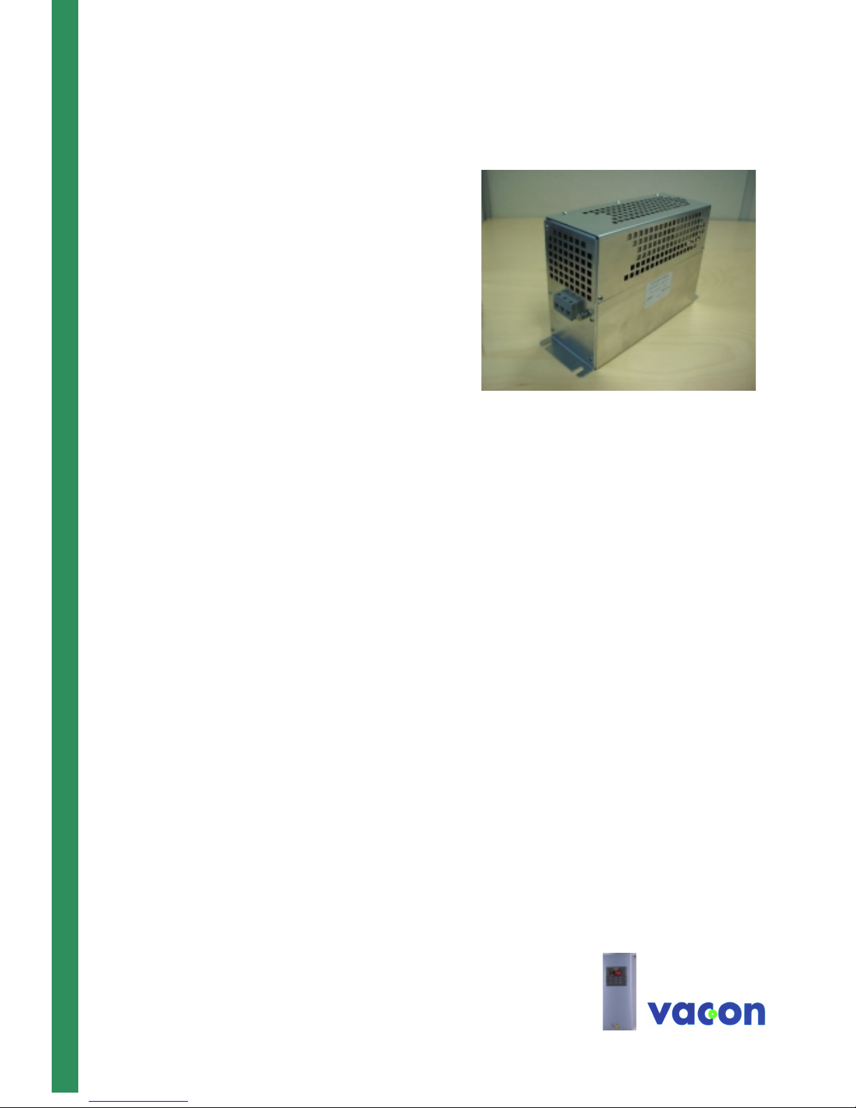
RFI-filters
Du/dt-filters
Sinus filters
Subject to changes without notice.
Page 2
Page 2 Filter Manual Vacon
Vacon Oyj Phone: +358-201-2121 Fax: +358-201-212 205
email: vacon@vacon.com http://www.vacon.com
Table of contents
1. General 3
2 Filter types 4
2.1 RFI-filters 4
2.2 du/dt filters 6
2.3 Sinus filters 10
Note! All internal components and component boards, with the exception of the galvanically separated input and output terminals are connected to high voltage when the
frequency converter is connected to the mains. It is extremely dangerous to touch
these live parts. Touch may cause severe injury or death
The I/O terminals are separated from the high potential of the mains, but the relay outputs and other I/O terminals may carry high voltages even if the frequency converter is
not connected to the mains.
Do not perform any high pot tests (megger) on the Vacon_SIN_B filters
The Vacon_RFI_A0 filters are intended for use in earthed supplies only
For unearthed (IT) supplies, contact our representative or us.
Page 3

Vacon Filter Manual Page 3
1 General
Modern frequency converters do not supply a smoothly changing AC voltage , but a
pulsed DC voltage to the motor. The
pulses have very steep flanks, the du/dt
may reach several kV/µs. These steep
pulses may be dangerous to the insulation
of the motor. The pulses may also cause
various disturbing currents in galvanically
connected cables as well as radiated interference. The radiated interference is
usually grounded by the metallic enclosure
of the converter and does not cause any
problems in the environment. The galvanically coupled interference may have to be
filtered in order to achieve EMC compliance. The converter may also have to be
protected against various overvoltages
occurring in the supply.
Both input and output filters are available
for the Vacon CX_ range of drives. These
filters help compliance with the EMC
regulations. On the input side RFI filters
and additional chokes can be mounted, on
the output side du/dt filters or sinus filters.
No other filters are necessary. The basic
connection is shown in Figure 1-1
Figure 1-1. The basic filtering principle of the Vacon CX_ filters. 1 = input filters, 2 = frequency
converter, 3 = output filter.
Type designation
VACON 250 RFI 4 A 0 AA
250 = Maximum current [A]
RFI = filter type
RFI = radio frequency filter
DUT = du/dt-filter
SIN = sinusoidal filter
CHK = output choke
4 = nominal voltage:
2 = 200 V
4 = 400 V
5 = 500 V
6 = 690 V
A = Filter type:
A = input filter
B = Output filter
C = Both
0 = Enclosure class
0 = IP00
2 = IP20
AA = Special
Page 4
Page 4 Filter Manual Vacon
Vacon Oyj Phone: +358-201-2121 Fax: +358-201-212 205
email: vacon@vacon.com http://www.vacon.com
2. Filter types
2.1 RFI-filters
The table below shows the filters used in
order to make the Vacon CX___N range of
frequency converters comply with
EN50082-2 for the industrial environment
and with EN61800-3 for the domestic and
industrial environment. The filters must be
correctly installed and grounded.
There are no standards at present for ITsupplies (floating supplies)
The Vacon CX__ frequency converters
comply with the immunity requirements of
EN50081 and EN 61800-3 as standard.
Note that the filters 16 – 100 RFI5C2 are
designed to fit mechanically directly to the
corresponding drive. All other s are lo os e
and must be connected to the drive separately.
3 x 500, 400 V, 50/60 Hz
T 40/F, IP00
Fastening dimensions
Motor current
A
Type a b c n2 n1 d Weight Terminals Power loss
at IVT/3.6
kHz
mm mm mm mm mm mm kg mm2
16 Vacon 16 RFI 5C2 241 120 130 95 7 6
15
43 Vacon 43 RFI 5C2 267 165 157 127 9 16
45
100 V acon 100 RFI 5C2 370 253 220 180 9 50/70
70
210 V acon 210 RFI 5A0 740 180 132 100 720 8 150
100
400 V acon 400 RFI 5A0 564 300 160 210 275 12 18,5 M12
65
600 V acon 600 RFI 5A0 564 300 160 210 275 12 20,5 M12
87
900 V acon 900 RFI 5A0 564 300 160 210 275 12 20,5 M12
104
1200 Vacon 1200 RFI 5A0 564 300 160 210 275 12 20,5 M12
146
3 x 690 V, 50/60 Hz
T 40/F, IP00
Fastening dimensions
Motor current
A
Type a b c n2 n1 d Weight Terminals Power loss
at IVT/3.6
kHz
mm mm mm mm mm mm kg mm2
42 Vacon 42 RFI 6A0 329 80 185 314 55 6 2,8 AWG8
100 Vacon 100 RFI 6A0 379 90 220 364 65 6, 5 5,8 50
185 Vacon 185 RFI 6A0 438 110 240 413 80 6,5 11,5 95
300 Vacon 300 RFI 6A0 564 300 160 210 275 12 17 M8
48
400 Vacon 400 RFI 6A0 564 300 160 210 275 12 19,5 M10
65
500 Vacon 500 RFI 6A0 564 300 160 210 275 12 19,5 M10
75
900 Vacon 900 RFI 6A0 564 300 160 210 275 12 19,5 M12
104
Page 5

Vacon Filter Manual Page 5
Figure 2 –1 Filters Vacon 16 – 100 RFI 5C2
Figure 2 –2 F ilters Vacon Vacon xxx RF I 6A0 and 5A0
c
bn2
a
n1
T
Page 6

Page 6 Filter Manual Vacon
Vacon Oyj Phone: +358-201-2121 Fax: +358-201-212 205
email: vacon@vacon.com http://www.vacon.com
2.2 dU/dt filters
2.2.1 dU/dt – maker Platthaus
The Vacon CX- ranges use IGBT transistors as the output element. These semiconductors give the correct voltage to the
motor, switching it at a very high speed, 2
- 4 kV/µs. This high speed will, under certain circumstances, cause extra voltage
stress on the main insulation of the motor.
Usually there are no problems with motors
designed for a 400 V supply. Such motors
are usually designed for a voltage level of
1200 V, which exceeds the frequency
converter induced stress.
In 500 V supplies the motor has to withstand at least 1600 V. A dU/dt filter is often
required with these motors in order not to
exceed the allowable voltage stress.
In 690 V supplies the motor has to stand
at least 1800 V. A dU/dt filter is required in
these cases.
! In uncertain cases, confirm the rating
of the motor in frequency converter application with the motor manufacturer.
The dU/dt filter also reduces ground currents, easing the job of earth-fault protectors. They also lessen the impact of the
various sources of bearing current.
All filters are IP00
The filters are LC filters, with a cut-off frequency of about 500 kHz. The exact value
changes due to component tolerances and
available standard values.
NOTE! Set the switching frequency parameter to correspond the value printed
on nameplate of the filter.
3 x 230, 400, 500 V, 50/60 Hz
fs = 3,6 kHz, T 40/F, IP00, VBG4
Fastening dimensions
Motor current
A
Type a b c n2 n1 d Weight Terminals Power loss
at IVT/3.6
kHz
mm mm mm mm mm mm kg mm2 W
8 VACON 8 DUT 5 B 0 100 110 180 60 48 4 1,2 4
15 VACON 15 DUT 5 B 0 125 110 200 100 55 5 3 6
42 VACON 42 DUT 5 B 0 155 125 225 130 72 8 7 16
96 VACON 96 DUT 5 B 0 190 135 260 170 78 8 12 35
160 V ACON 160 DUT 5 B 0 240 175 310 190 106 11 22 95
220 V ACON 220 DUT 5 B 0 240 195 310 190 126 11 30 95
325 V ACON 325 DUT 5 B 0 320 225 410 240 134 11 46 240
410 V ACON 410 DUT 5 B 0 400 320 530 310 126 11 65 2 x M12
510 V ACON 510 DUT 5 B 0 400 350 530 310 156 11 95 2 x M12
600 V ACON 600 DUT 5 B 0 420 340 560 370 167 11 130 2 x M12
750 V ACON 750 DUT 5 B 0 480 390 800 430 185 11 200 2 x M12
840 V ACON 840 DUT 4 B 0 480 420 800 430 210 11 230 2 x M12
˜
Page 7

Vacon Filter Manual Page 7
3 x 690 V, 50/60 Hz
fs = 1,5 kHz, T 40/F, IP00, VBG4
Fastening dimensions
Motor current
A
Type a b c n2 n1 d Weight Terminals Power loss
at IVT/3.6
kHz
mm mm mm mm mm mm kg mm2
14 VACON 14 DUT 6 B 0 120 110 170 60 48 4 1,3 10 15
23 VACON 23 DUT 6 B 0 125 110 190 100 55 5 3 10 45
35 VACON 35 DUT 6 B 0 155 110 220 130 57 8 4,5 16 70
62 VACON 62 DUT 6 B 0 190 110 255 170 58 8 9 35 100
100 V ACON 100 DUT 6 B 0 190 135 255 170 78 8 12 35 120
145 V ACON 145 DUT 6 B 0 240 160 310 190 100 11 20 70 180
222 V ACON 222 DUT 6 B 0 240 200 310 190 126 11 30 95 210
287 V ACON 287 DUT 6 B 0 300 230 400 240 134 11 46 150 350
325 V ACON 325 DUT 6 B 0 360 220 450 310 126 11 65 240 480
390 V ACON 390 DUT 6 B 0 360 240 450 310 141 11 75 240
Figure 2-3 Typical relative attenuation for dU/dt and sinusoidal filters. Corner frequency about
500 kHz for dU/dt filters, about half default switching frequency for sinusoidal filters.
n2
V1
PE
U1
a
V2W1 U2 W2
n1
b
d
c
Figure 2-4. Main dimensions for dU/dt filters ≤ 410
A/400V, ≤400A/500V and ≤360A/690V
-6
-5
-4
-3
-2
-1
0
1
0,01 0,02 0,05 0,1 0,2 0,5 1 2 5 10 20 50 100 200 500
Page 8

Page 8 Filter Manual Vacon
Vacon Oyj Phone: +358-201-2121 Fax: +358-201-212 205
email: vacon@vacon.com http://www.vacon.com
2.2.2 dU/dt filter with resistance
The SH filter differs from the standard in that they contain a resistance to reduce the ‘ringing’
created by the interaction of the choke and the stray inductance of the motor. Functionally
they are equivalent.
3 x 400 - 690 V , 50/60 Hz
fswitching = 16 kHz max., T 40/F, IP00
max. output f=60 Hz
max. motor cable length=100 m
Fastening dimensions
Motor current
A
Type a b c n2 n1 d Power
loss at
IVT/3.6
kHz
Terminals
mm2
Weight
[kg]
18 Vacon 18DUT 6B0 SH 260 82 160 240 60 M4 4,8
42 Vacon 42DUT 6B0 SH 350 110 190 330 70 M6 9
60 Vacon 60DUT 6B0 SH 470 140 235 440 100 M8 50 15
110 Vacon 110DUT 6B0 SH 470 140 235 440 100 M8 50 22
210 Vacon 210DUT 6B0 SH 564 300 160 420
(2 x
210)
275 M9 M8 32
410 Vacon 410DUT 6B0 SH 680 300 180 424
(2 x
212
275 M9 65 M10 60
600 Vacon 600DUT 6B0 SH 850 300 160 630
(3 x
210)
275 M9 87 M10 80
3˜M
L
C
R
Page 9

Vacon Filter Manual Page 9
c
bn2
a
n1
T
Page 10

Page 10 Filter Manual Vacon
Vacon Oyj Phone: +358-201-2121 Fax: +358-201-212 205
email: vacon@vacon.com http://www.vacon.com
2.3 Sine-filters
If you wish to avoid all extra voltage
stresses on the motor at all voltages, sinefilters can be used. They remove all high
frequency components from the motor
voltage. The voltage stresses on the motor
correspond to those existing in normal
DOL use on a source of the same voltage.
Note! Check that the set switching frequency corresponds the value printed
on nameplate of the filter.
3 x 690 V, 50/60 Hz
fs = 1,5 kHz, T 40/F, IP00, VBG4
Fastening dimensions
Motor current
A
Type a b c n2 n1 d Weight Termi nal s Power loss
at IVT/3.6
kHz
A mmmmmmmmmmmm kg mm2
10 VACON 10 SIN 6 B 0 160 190 155 130 72 8 7 10 85
14 VACON 14 SIN 6 B 0 190 190 185 170 68 8 12 10 110
19 VACON 19 SIN 6 B 0 210 220 210 180 82 8 16 10 140
23 VACON 23 SIN 6 B 0 240 220 240 190 96 11 20 10 170
26 VACON 26 SIN 6 B 0 240 225 240 190 100 11 22 10 180
35 VACON 35 SIN 6 B 0 240 240 280 190 121 11 28 16 210
42 VACON 42 SIN 6 B 0 300 250 350 240 121 11 33 36 290
52 VACON 52 SIN 6 B 0 300 250 350 240 121 11 35 36 290
62 VACON 62 SIN 6 B 0 300 270 350 240 134 11 38 36 350
85 VACON 85 SIN 6 B 0 360 270 400 310 141 11 45 50 480
100 VACON 100 SIN 6 B 0 360 380 400 310 156 11 63 70 600
122 VACON 122 SIN 6 B 0 360 400 400 310 156 11 63 70 600
145 VACON 145 SIN 6 B 0 420 400 470 370 152 11 70 95 680
185 VACON 185 SIN 6 B 0 420 430 490 370 182 11 85 150 750
222 VACON 222 SIN 6 B 0 480 430 540 430 210 11 150 150 900
287 VACON 287 SIN 6 B 0 480 460 560 430 240 11 170 240 950
360 VACON 360 SIN 6 B 0 480 460 560 430 240 11 170 240 950
430 VACON 430 SIN 6 B 0 480 520 560 430 240 11 180 240
3 x 500 V, 50/60 Hz fs = 3,6 kHz, T 40/F,
IP00, VBG4
Fastening dimensions
Motor current
A
Type a b c n2 n1 d Weight Termi nal s Power loss
at IVT/3.6
kHz
mm mm mm mm mm mm kg mm2
4,7 VACON 4,7 SIN 5 B 0 100 110 170 60 48 4 1,2 2,5 40
10 VACON 10 SIN 5 B 0 125 110 190 100 45 5 2,2 4 70
18 VACON 18 SIN 5 B 0 190 140 190 170 68 8 11 10 110
32 VACON 32 SIN 5 B 0 210 150 210 180 82 8 14 10 140
60 VACON 60 SIN 5 B 0 240 195 295 190 121 11 26 35 210
90 VACON 90 SIN 5 B 0 300 230 360 240 146 11 55 70 400
150 VACON 150 SIN 5 B 0 360 250 420 310 141 11 75 95 540
210 VACON 210 SIN 5 B 0 360 270 440 310 156 11 85 150 600
260 VACON 325 SIN 5 B 0*) 420 285 500 370 182 11 120 150 750
320 VACON 320 SIN 5 B 0 480 350 560 430 240 11 250 240 950
400 VACON 400 SIN 5 B 0 480 350 560 430 240 11 250 240 950
460 VACON 460 SIN 5 B 0 480 460 560 430 242 11 280 M 12
600 VACON 600 SIN 5 B 0 920 470 850 840 238 18 450 M 12
672 VACON 750 SIN 5 B 0 920 500 850 840 268 18 540 M 12
Page 11

*) NOTE: The same filter as 325 A/400 V, can be used only to 260 A/500 V.
3 x 230, 400 V, 50/60 Hz
fs = 3,6 kHz, T 40/F, IP00, VBG4
Fastening dimensions
Motor current
A
Type a b c n2 n1 d Weight Termi nal s Power loss
at IVT/3.6
kHz
4,5 VACON 4,7 SIN 5 B 0 125 110 180 100 45 5 2,2 4 40
10 VACON 10 SIN 5 B 0 155 110 210 130 57 8 4,7 4 70
18 VACON 18 SIN 5 B 0 190 140 190 170 68 8 11 10 110
32 VACON 32 SIN 5 B 0 210 150 210 180 82 8 14 10 140
60 VACON 60 SIN 5 B 0 240 195 295 190 121 11 26 35 210
90 VACON 90 SIN 5 B 0 300 230 360 240 146 11 55 70 400
150 VACON 150 SIN 5 B 0 360 250 420 310 141 11 75 95 540
210 VACON 210 SIN 5 B 0 420 285 500 370 182 11 120 150 750
325 VACON 325 SIN 5 B 0 420 315 510 370 212 11 150 240 800
410 VACON 410 SIN 4 B 0 480 350 560 430 240 11 250 240 950
510 VACON 510 SIN 4 B 0 480 460 620 430 242 11 270 M 12
580 VACON 600 SIN 5 B 0 920 470 850 840 238 18 450 M 12
750 VACON 750 SIN 5 B 0 920 500 850 840 268 18 540 M 12
840 VACON 840 SIN 5 B 0 920 500 850 840 268 18 540 M 12
Figure 2-6. Filters <13A/400 V, <11 A/500 V and 10 A/690 V
PE
n2
a
W1U1 U2 V1 V2 W2
n1
b
d
c
Page 12

Page 12 Filter Manual Vacon
Vacon Oyj Phone: +358-201-2121 Fax: +358-201-212 205
email: vacon@vacon.com http://www.vacon.com
1)IVT/3,6kHz
2) See Figures 2-6 and 2-7.
Figure 2-7 Main dimensions for sine filters ≥ 18 A/400V,
≥
15 A/500 V and ≥ 14 A/690 V
n2
a
W2U1 U2 V2V1 W 1
n1
b
d
c
Page 13

ud289d.doc
8.1.2001
VACON OYJ
PL 25
Runsorintie 7
65381 VAASA
Tel: +358-201-2121
Fax: +358-201-212 205
24-hour support: +358-400-8371 150
E-mail: vacon@vacon.com
http://www.vacon.com
 Loading...