

Page 1

F O R S M O O T H C O N T R O L
I/O-expander board
installation manual
(Vacon CXS-range)
Subject to changes without notice.
VACON
CX/CXL/CXS
FREQUENCY CONVERTERS
Page 2

Vacon Page 1 (15)
I/O-expander board installation (Vacon CXS-range)
Vacon Plc Tel: +358-201 2121 Fax: +358-201 212 205
Service: +358-40-8371 150 E-mail: vacon@vacon.com
http://www.vacon.com
CONTENTS
1 GENERAL .......................................... 2
1.1 Vacon CX100OPT ...................... 2
1.2 Vacon CX101OPT ...................... 2
1.3 Vacon CX102OPT ...................... 2
1.4 Vacon CX103OPT ...................... 2
1.5 Vacon CX104OPT ...................... 3
1.6 Vacon fieldbus boards ............... 3
2 SPECIFICATIONS ............................ 4
3 INSTALLATION................................. 5
3.1 General ..................................... 5
3.2 Installation ................................ 6
4 CONTROL CONNECTIONS ........1 1
4.1 Vacon CX100OPT .................... 11
4.2 Vacon CX101OPT .................... 12
4.3 Vacon CX102OPT .................... 13
4.4 Vacon CX103OPT .................... 14
4.5 Vacon CX104OPT .................... 15
Page 3

Page 2 (15) Vacon
I/O-expander board installation (Vacon CXS-range)
Vacon Plc Tel: +358-201 2121 Fax: +358-201 212 205
Service: +358-40-8371 150 E-mail: vacon@vacon.com
http://www.vacon.com
1 GENERAL
Due to the compact frame size of the Vacon CXS series all I/O-expander boards need
to be installed in a separate box (Vacon CXSOPTBKIT), except the smaller, specifically
for Vacon CXS designed boards (Vacon CX104OPT, CX105OPT, CX107OPT,
CX108OPT). If ordered together with the option board these will be preinstalled.
1.1 Vacon CX100OPT
The available I/O can be increased by using the Vacon CX100OPT I/O-expander
board:
- 5 digital inputs (standard signals)
- 2 analogue inputs (standard signals)
- 3 relay outputs (standard signals)
- analogue output (programmable)
- thermistor input (can be directly connected to the motor
thermistors to monitor the motor temperature)
- encoder input
Typical use: Closed Loop Vector Control
1.2 Vacon CX101OPT
The available I/O can be increased by using the Vacon CX101OPT I/O-expander
board:
- 5 digital inputs (standard signals)
- relay output (standard signal)
- thermistor input (can be directly connected to the motor thermistors to monitor
the motor temperature)
Typical use: thermistor input required
1.3 Vacon CX102OPT
The available I/O can be increased by using the Vacon CX102OPT I/O-expander
board:
- 5 digital inputs (standard signals)
- 2 analogue inputs (standard signals)
- 3 relay outputs (standard signals)
- analogue output (programmable)
- thermistor input (can be directly connected to the motor thermistors to
monitor the motor temperature)
- encoder input
Typical use: Closed Loop Vector Control
1.4 Vacon CX103OPT
The available I/O can be increased by using the Vacon CX103OPT I/O-expander
board:
- 5 digital inputs (standard signals)
- 3 relay outputs (standard signals)
- analogue output (programmable)
- thermistor input (can be directly connected to the motor thermistors to monitor
the motor temperature)
Typical use: thermistor input and additional analogue output required
Page 4

Vacon Page 3 (15)
I/O-expander board installation (Vacon CXS-range)
Vacon Plc Tel: +358-201 2121 Fax: +358-201 212 205
Service: +358-40-8371 150 E-mail: vacon@vacon.com
http://www.vacon.com
1.5 Vacon CX104OPT
The available I/O can be increased by using the Vacon CX104OPT I/O-expander
board:
- encoder input
Typical use: Closed Loop Vector Control
1.6 Fieldbus boards
Vacon fieldbus boards can be installed in the Vacon CXS range frequency converters
as I/O-expander boards. The needed information to install/commission fieldbus
boards can be found in the respective Vacon fieldbus manual.
- Vacon CX 200OPT (Interbus-S)
- Vacon CX 201OPT (Modbus)
- Vacon CX 202OPT (Profibus-DP)
- Vacon CX 203OPT (LonWorks)
- Vacon CX 204OPT (C - b u s )
- Vacon CX 205OPT (SDS-bus)
Page 5
Page 4 (15) Vacon
I/O-expander board installation (Vacon CXS-range)
Vacon Plc Tel: +358-201 2121 Fax: +358-201 212 205
Service: +358-40-8371 150 E-mail: vacon@vacon.com
http://www.vacon.com
2 SPECIFICATIONS
Safety Fulfills EN50178, C-UL and EN60204-1 standards
Control Analogue voltage, input 0—± 10 V, Ri ≥ 200 kΩ
connections Analogue current, input 0(4)—20 mA, Ri = 250 Ω
Digital input 24 V: "0" ≤10 V, "1" ≥18 V , Ri > 5 kΩ
Aux. voltage 24 V (±20%), max. 50 mA
Reference voltage 10 V ±3 %, max. 10 mA
Analogue current, output 0(4)—20 mA, RL = 500 Ω , resolution 10 bit, accuracy ≤±2%
Analogue voltage, output 0(2)—10 V, RL ≥ 1 kΩ , resolution 10 bit, accuracy ≤±2%
Relay output Max. switching voltage: 300 V DC, 250 V AC
Max. switching load: 8A / 24 V DC
0,4 A / 300 V DC
2 kV A / 250 V AC
Max. continuous load: 2 A rms
Thermistor input R
trip
= 4.7 kΩ
Encoder input 24 V: "0" ≤10 V, "1" ≥18 V, Ri = 2.2 kΩ
5 V: "0" ≤ 2 V, "1" ≥ 3 V, Ri = 330 Ω
Table 2-1 Specifications. (All the control connections are not found on every I/O-expander board, for
specific information see Chapters 1 and 4.)
The control connections are isolated from the mains potential and the I/O ground is
connected to the frame of the inverter via a 1-MΩ resistor and 4,7-nF capacitor*). The
control I/O ground can be connected directly to the frame by changing the position of the
jumper X4 (GND ON/OFF) to the ON-position. Digital inputs and relay outputs are also
isolated from the I/O ground.
*) Default value (X4 is GND OFF- position).
NOTE!
Internal components and circuit boards (except the isolated I/O terminals) are at
mains potential when the frequency converter is connected to the mains. This
voltage is extremely dangerous and may cause death or severe injury if you
come into contact with it.
The control I/O terminals are isolated from the mains potential, but the relay
outputs and other I/O's may have a dangerous voltage connected even if the
power is disconnected from the frequency converter.
Page 6
Vacon Page 5 (15)
I/O-expander board installation (Vacon CXS-range)
Vacon Plc Tel: +358-201 2121 Fax: +358-201 212 205
Service: +358-40-8371 150 E-mail: vacon@vacon.com
http://www.vacon.com
1
3 INSTALLATION
3.1. General
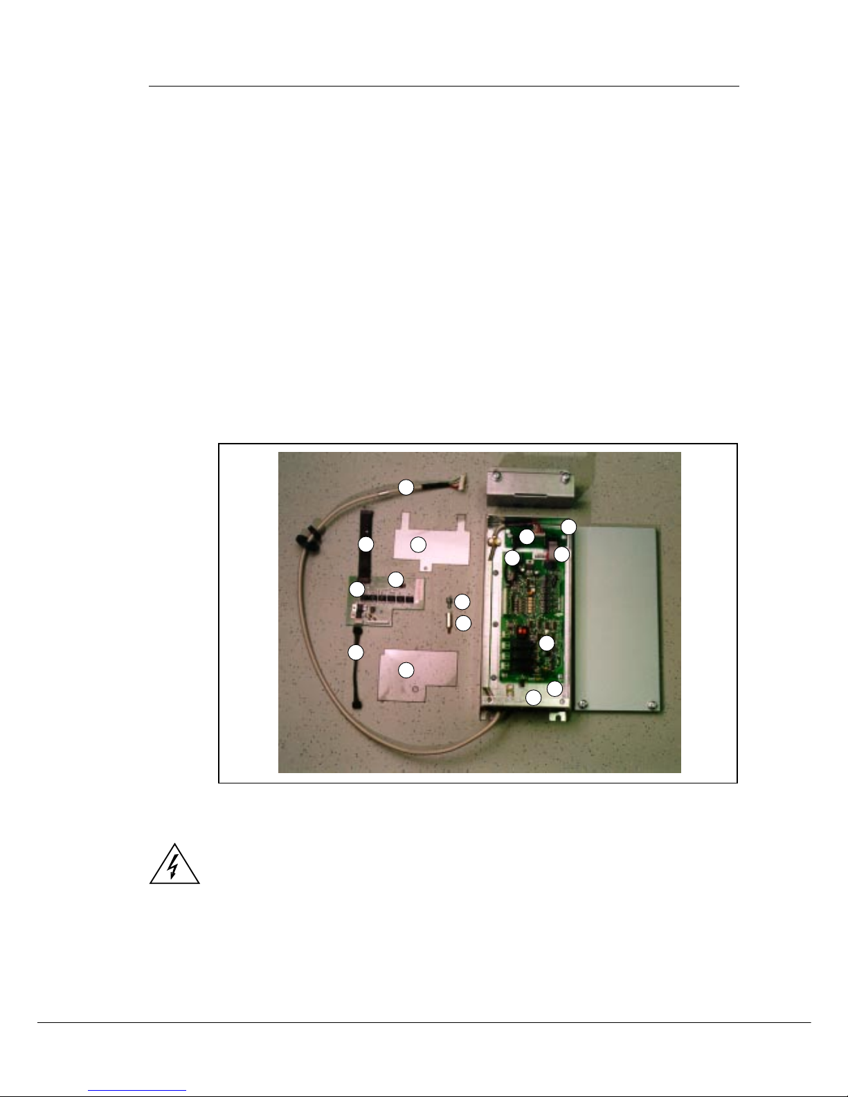
Check that your have received all the required parts (Figure 3-1):
- I/O-repeater board (1) and I/O-pole shielded data cable (2)
- check that you have also received the jumper for I/O- repeater board
terminal X5 (3)
- 4-pole power cable (4)
- protection foil below (5) and above (6) the I/O-reapeater board
- stand sleeve (7)
- screw for fixing I/O-repeater board (8)
- 12-pole communication cable (9)
- opition box (10)
- I/O-expander board (11) (check that the typecode is corresponds to
your order)
- I/O-interface board (12)
- 10-pole data cable (13)
- 4-pole power cable (14)
- screws for I/O-expander board (15)
- screws for I/O-interface board (16)
Figure 3-1. I/O-expander board parts.
If the delivery does not match your order, please contact the supplier immediately. Only
a competent electrician should carry out the electrical installation.
Before doing any commissioning, carefully read the safety instructions in the "USER'S
MANUAL, V ACON CX/CXL/CXS", Chapter 1, SAFETY.
Disconnect the frequency converter from the mains. NOTE: Also the control circuits!
Wait further 5 minutes before opening the cover of the frequency converter. Verify by
measuring that the frequency converter is safe to touch.
2
3
4
5
6
7
8
9
10
11
12
13
14
15
16
Page 7

Page 6 (15) Vacon
I/O-expander board installation (Vacon CXS-range)
Vacon Plc Tel: +358-201 2121 Fax: +358-201 212 205
Service: +358-40-8371 150 E-mail: vacon@vacon.com
http://www.vacon.com
Table 3-2. I/O-expander board installation (continues ...).
1
2
4
Remove the control panel, control panel base (4 screws) and the jumper X4 from the
control board.
3
3.2 INSTALLATION
I/O-repeater board (1) should be installed above the control board inside the frequency converter. The I/O-expander board (10) and I/O-inter face board (11) should be installed in the
option box. Follow the instructions below (see Table 3-2).
Check that the jumper for I/O-repeater board (1) is in the right position in terminal X5 (3).
The position of the jumper must be chosen according to the I/O-expander board (11)
:
- If I/O-expander board CX101OPT or 103OPT
is in use, jumper must be in position A.
- If I/O-expander board CX100OPT or 102OPT
is in use, jumper must be in position B.
- If one of the following fielbus boards is in use:
CX200OPT , CX201OPT, CX202OPT or
CX203OPT, jumper must be in position C.
(Positon D is not in use).
X5
X4
Make sure that the cable of the control panel
cover is connected to the control board X1 terminal. Connect the 4-pole power cable (4) to
the control board X5 terminal (The power cable
can also be connected to the X6-terminal, if the
power cable from the power board is connected
to the X5-terminal.)
Set the protection foil (5) above the control
board as shown in the picture. Make sure that
the protection foil is correctly located, the hole
in the foil will must be located above the stand
sleeve.
X5
Remove the fixing screw from the control board
and replace it with the stand sleeve (7).
5
7
Page 8

Vacon Page 7 (15)
I/O-expander board installation (Vacon CXS-range)
Vacon Plc Tel: +358-201 2121 Fax: +358-201 212 205
Service: +358-40-8371 150 E-mail: vacon@vacon.com
http://www.vacon.com
Connect the shielded data cable for I/
O-repeater board (2) to the control
board terminal X14.
7
5
Set the protection foil (6) above the I/O-repeater board as shown in the picture. Make sure
that the protection foil is correctly located, push the "arms" of the protection foil under the
control panel cover. Fasten the I/O-repeater board and protection foil to the stand sleeve (7)
with the screw .
X14
Install the control panel cover with 4
screws.
6
8
Connect the power cable (4) to the I/O-repeater terminal X1 and communication cable (9) to
the I/O-repeater terminal X3. Uncover carefully the shield of the communication cable (max.
1,5 cm), tighten up to the metal clamp (of the cable) and earth the cable to the frequency
converter ground as shown in the picture.
Table 3-2. I/O-expander board installation (continues ...).
4
9
6
7
Page 9

Page 8 (15) Vacon
I/O-expander board installation (Vacon CXS-range)
Vacon Plc Tel: +358-201 2121 Fax: +358-201 212 205
Service: +358-40-8371 150 E-mail: vacon@vacon.com
http://www.vacon.com
Check the connections and make sure that there are no foreign objects inside the frequency
converter.
Close the cover of the frequency converter.
9
10
Install the jumper removed from the control board X4 terminal into the I/O-expander board
terminal X9. Note: the jumper can be connected in ON or OFF position,see V acon CX/CXL/
CXS User's manual, Chapter 6.2.2.
13
If you have the option box with the I/O-expander (11) and I/
O-interface boards (12) pre-installed, jump to section 17.
Mount the I/O-expanderboard (11) and I/O-interface board
(12) in the option box (10) with the screws.
11
Connect data cable (13) between terminal X14 in
the I/O-interface board (12) and terminal X14 in
the I/O-expander board (11)).
X14
X14
12
Connect power cable (14) between terminal X6
in the I/O-interface board (12) and terminal
X6 in the I/O-expander board (11).
X6
X6
Table 3-2. I/O-expander board installation (continues ...).
X9
Page 10

Vacon Page 9 (15)
I/O-expander board installation (Vacon CXS-range)
Vacon Plc Tel: +358-201 2121 Fax: +358-201 212 205
Service: +358-40-8371 150 E-mail: vacon@vacon.com
http://www.vacon.com
Connect the communication cable (9) to the I/O-expander board
X15 terminal (12). Earth the communication cable to the option box
ground.
X15
14
15
Connect the necessary control signals. If a fieldbus board is in use, see separate manual for
more specific information.
X8
16
If an encoder input (closed loop control) is to
be used and the encoder works at a 5V level,
move three jumpers from terminal X5 to terminal
X8. If the encoder works at 24V, then terminal
X8 should be left free.
Check the connections and make sure that there are no foreign objects inside the option box.
Before connecting the mains make sure that the cover of the option box and frequency converter are closed.
Set the parameters of I/O-expander board according to the Vacon "Five in One+" -application manual (parameter group 3).
17
18
T able 3-2. I/O-expander board installation.
Page 11

Page 10 (15) Vacon
I/O-expander board installation (Vacon CXS-range)
Vacon Plc Tel: +358-201 2121 Fax: +358-201 212 205
Service: +358-40-8371 150 E-mail: vacon@vacon.com
http://www.vacon.com
Figure 3-2. Frequency converter and external I/O-expander box installation (unit sizes M3 and M4B).
I/O-expander box can also be installed beside the frequency converter (unit sizes M3, M4B and M5B).
Page 12

Vacon Page 11 (15)
I/O-expander board installation (Vacon CXS-range)
Vacon Plc Tel: +358-201 2121 Fax: +358-201 212 205
Service: +358-40-8371 150 E-mail: vacon@vacon.com
http://www.vacon.com
4 CONTROL CONNECTIONS
4.1 Vacon CX100OPT
Signal from
motor thermistors *)
Figure 4-1 Control connections of V acon CX100OPT.
Ter minal Signal Description
201 +10V
ref
Reference output Voltage for a potentiometer, etc.
202 U
in
+ Analogue input, voltage Not in use
range 0—10 V DC
203 GND I/O ground Ground for reference and controls
204 I
in
+ Analogue input, current Not in use
205 I
in
- range 0—20 mA
206 +24V Control voltage output Voltage for switches, etc. max. 50 mA
207 GND I/O ground Ground for reference and controls
208 CMC Common for DIC1-DIC5 Connect to GND or + 24 V
209 DIC1 External fault Contact open = no fault
(closing contact) Contact closed = fault
210 DIC2 Run disable Cont. open = start of motor enabled
Cont. closed= start of motor disabled
211 DIC3 Acceler. / Decel. time Contact open = time 1 selected
selection Contact closed = time 2 selected
212 DIC4 Jogging speed selection Contact open = no action
Contact closed = jogging speed
213 DIC5 Fault reset Contact open = no action
Contact closed = fault reset
214 DI6A+ Pulse input A
215 DI6A- (differential input)
216 DI7B+ Pulse input B 90 degrees phase shift compared
217 DI7B- (differential input) to pulse input A
218 D I 8 Z + Pulse input C one pulse per one revolution
219 DI8Z- (differential input)
220 I
out
+ Analogue output Programmable
0—20 mA/RL max. 500 Ω (Motor current as default value)
221 T I + Thermistor input
222 TI223 RO3/1 Relay output 3 READY
224 RO3/2
225 RO4/1 Relay output 4 RUN
226 RO4/2
227 RO5/1 Relay output 5 FAULT
228 RO5/2
*) NOTE! Thermistor input (terminals 221 and 222) must be shorted if not used.
Enco der
Page 13

Page 12 (15) Vacon
I/O-expander board installation (Vacon CXS-range)
Vacon Plc Tel: +358-201 2121 Fax: +358-201 212 205
Service: +358-40-8371 150 E-mail: vacon@vacon.com
http://www.vacon.com
Ter minal Signal Description
206 +24V Control voltage output V oltage for switches, etc. max. 50 mA
207 GND I/O ground Ground for reference and controls
208 CMC Common for DIC1-DIC5 Connect to GND or + 24 V
209 DIC1 External fault Contact open = no fault
(closing contact) Contact closed = fault
210 DIC2 Run disable Cont. open = start of motor enabled
Cont. closed= start of motor disabled
211 DIC3 Acceler. / Decel. time Contact open = time 1 selected
selection Contact closed = time 2 selected
212 DIC4 Jogging speed selection Contact open = no action
Contact closed = jogging speed
213 DIC5 Fault reset Contact open = no action
Contact closed = fault reset
214 N.C. Not connected
215 N.C. Not connected
221 TI+ Thermistor input
222 TI+
225 RO4/1 Relay output 4 RUN
226 RO4/2
4.2 Vacon CX101OPT
Signal from
motor thermistors *)
*) NOTE! Thermistor input (terminals 221 and 222) must be shorted if not used.
Figure 4-2 Control connections of V acon CX101OPT.
Page 14

Vacon Page 13 (15)
I/O-expander board installation (Vacon CXS-range)
Vacon Plc Tel: +358-201 2121 Fax: +358-201 212 205
Service: +358-40-8371 150 E-mail: vacon@vacon.com
http://www.vacon.com
Ter minal Signal Description
201 +10V
ref
Reference output Voltage for a potentiometer, etc.
202 U
in
+ Analogue input, voltage Not in use
range 0—10 V DC
203 GND I/O ground Ground for reference and controls
204 U
in
+ Analogue input, voltage Not in use
205 U
in
- range 0—10 V DC
206 +24V Control voltage output Voltage for switches, etc. max. 50 mA
207 GND I/O ground Ground for reference and controls
208 CMC Common for DIC1-DIC5 Connect to GND or + 24 V
209 DIC1 External fault Contact open = no fault
(closing contact) Contact closed = fault
210 DIC2 Run disable Cont. open = start of motor enabled
Cont. closed= start of motor disabled
211 DIC3 Acceler. / Decel. time Contact open = time 1 selected
selection Contact closed = time 2 selected
212 DIC4 Jogging speed selection Contact open = no action
Contact closed = jogging speed
213 DIC5 Fault reset Contact open = no action
Contact closed = fault reset
214 DI6A+ Pulse input A
215 DI6A- (differential input)
216 DI7B+ Pulse input B 90 degrees phase shift compared
217 DI7B- (differential input) to pulse input A
218 DO1 Encoder direction output
21 9 DO2 Encoder divider 1/64 output
220 U
out
+ Analogue output Programmable
0—10 V DC/RL ≥ 1 kΩ (Motor voltage as default value)
221 T I + Thermistor input
222 TI223 RO3/1 Relay output 3 READY
224 RO3/2
225 RO4/1 Relay output 4 RUN
226 RO4/2
227 RO5/1 Relay output 5 FAULT
228 RO5/2
4.3 Vacon CX102OPT
Figure 4-3 Control connections of V acon CX102OPT.
Signal from
motor thermistors *)
*) NOTE! Thermistor input (terminals 221 and 222) must be shorted if not used.
Enco der
Page 15

Page 14 (15) Vacon
I/O-expander board installation (Vacon CXS-range)
Vacon Plc Tel: +358-201 2121 Fax: +358-201 212 205
Service: +358-40-8371 150 E-mail: vacon@vacon.com
http://www.vacon.com
4.4 Vacon CX103OPT
*) NOTE! Thermistor input (terminals 221 and 222) must be shorted if not used.
Figure 4-4 Control connections of V acon CX103OPT.
Te rminal Signal Description
206 +24V Control voltage output V oltage for switches, etc. max. 50 mA
207 GND I/O ground Ground for reference and controls
208 CMC Common for DIC1-DIC5 Connect to GND or + 24 V
209 DIC1 External fault Contact open = no fault
(closing contact) Contact closed = fault
210 DIC2 Run disable Cont. open = start of motor enabled
Cont. closed= start of motor disabled
211 DIC3 Acceler. / Decel. time Contact open = time 1 selected
selection Contact closed = time 2 selected
212 DIC4 Jogging speed selection Contact open = no action
Contact closed = jogging speed
213 DIC5 Fault reset Contact open = no action
Contact closed = fault reset
21 4 GND I/O ground
215 I
out
+ Analogue output Programble
0—20 mA/RL max. 500 Ω (Motor current as default value)
221 TI+ Thermistor input
222 TI 223 RO3/1 Relay output 3 READY
224 RO3/2
225 RO4/1 Relay output 4 RUN
226 RO4/2
227 RO5/1 Relay output 5 FAULT
228 RO5/2
Signal from
motor thermistors *)
Page 16

Vacon Page 15 (15)
I/O-expander board installation (Vacon CXS-range)
Vacon Plc Tel: +358-201 2121 Fax: +358-201 212 205
Service: +358-40-8371 150 E-mail: vacon@vacon.com
http://www.vacon.com
Ter minal Signal Description
201 +5 V Control voltage output Voltage for switches, max load
100-150 mA
203 GND I/O ground Ground for controls
206 +24V Control voltage output
207 GND I/O ground Ground for controls
214 DI6A+ Pulse input A
215 DI6A- (differential input)
216 DI7B+ Pulse input B
217 DI7B- (differential input)
218 DI R Encoder direction
21 9 DIV Encoder divider 1/1024
4.5 Vacon CX104OPT
More information on the Vacon CX104OPT encoder option board you will find in a
separate manual (ud318). Ask your distributor for more information.
Figure 4-5 Control connections of V acon CX104OPT.
Enco der
Page 17

VACON PLC
P.O. Box 25
Runsorintie 7
FIN-65381 VAASA
FINLAND
Phone: +358-201 2121
Fax: +358-201 212 205
Service: +358-40-8371 150
E-mail: vacon@vacon.com
http://www.vacon.com
Distributor:
U
D 00244C1, 19.10.2000
 Loading...