

Page 1

vacon
ac drives
canopen option board opte6
user manual
®
Page 2

Page 3

vacon • 3
TABLE OF CONTENTS
Document: DPD01091C
Release date : 13092017
1. Safety...............................................................................................................5
1.1 Danger................................................................................................................................5
1.2 Warnings ............................................................................................................................6
1.3 Earthing and earth fault protection ...................................................................................7
2. CANopen option board OPTE6 - General ..........................................................8
2.1 Overview .............................................................................................................................8
2.2 Software .............................................................................................................................8
2.2.1 CAN.....................................................................................................................................8
2.2.2 CANopen.............................................................................................................................8
3. CANopen protocol description .........................................................................9
3.1 NMT ....................................................................................................................................9
3.2 Node control protocols ....................................................................................................10
3.3 Error control protocols ....................................................................................................11
3.3.1 Heartbeat protocol ...........................................................................................................11
3.3.2 Node guarding protocol ...................................................................................................12
3.3.3 EMCY object......................................................................................................................12
3.4 SDO protocol ....................................................................................................................14
3.5 PDO protocol ....................................................................................................................15
3.5.1 PDO communication parameter record ..........................................................................15
3.5.2 COB ID ..............................................................................................................................16
3.5.3 Transmission type............................................................................................................17
3.5.4 PDO parameter mapping record .....................................................................................18
3.6 SYNC protocol ..................................................................................................................19
3.6.1 SYNC with counter ...........................................................................................................19
3.7 Communication objects ...................................................................................................21
3.7.1 0X1000 - Device Type .......................................................................................................21
3.7.2 0X1001 - Error Register ...................................................................................................21
3.7.3 0X1003 - Pre-defined Error Field ....................................................................................22
3.7.4 0X1005 - COB ID SYNC .....................................................................................................22
3.7.5 0X100C - Guard Time .......................................................................................................22
3.7.6 0X100D - Life Time Factor ...............................................................................................22
3.7.7 0X1014 - COB ID EMCY.....................................................................................................23
3.7.8 0X1016 - Heartbeat Consumer Entries............................................................................23
3.7.9 0X1017 - Producer Heartbeat Time .................................................................................24
3.7.10 0X1018 - Identify Object ...................................................................................................24
3.7.11 0X1019 - Synchronous counter overflow value ...............................................................24
3.7.12 0X1029 - Error behaviour.................................................................................................25
3.8 Saving and restoring the object dictionary ......................................................................25
3.8.1 0X1010 Store parameter field ..........................................................................................25
3.8.2 0X1011 Restore default parameters................................................................................25
4. CANopen option board OPTE6 - technical data...............................................27
4.1 General.............................................................................................................................27
4.2 CAN cable.........................................................................................................................27
4.2.1 Isolated ground connection .............................................................................................28
4.2.2 Recommended cable .......................................................................................................29
5. OPTE6 layout and connections .......................................................................30
5.1 Layout and connections ...................................................................................................30
5.2 LED Indications ................................................................................................................32
5.3 Jumpers ...........................................................................................................................33
6. Installation.....................................................................................................35
Local contacts: http://drives.danfoss.com/danfoss-drives/local-contacts/
Page 4

vacon • 4
6.1 Installation in VACON® 100.............................................................................................35
6.2 Prepare for use through fieldbus ....................................................................................37
6.3 Installation in VACON® 20...............................................................................................40
6.3.1 Frames MI1, MI2, MI3 ......................................................................................................40
6.3.2 Frames MI4, MI5 ..............................................................................................................43
6.4 Installation in VACON® 20 X and 20 CP ..........................................................................47
6.5 Installation in VACON® 100 X (Frames MM4-MM6)........................................................49
7. Commissioning ..............................................................................................53
7.1 OPTE6 panel parameters.................................................................................................53
7.1.1 OPTE6 additional panel parameters................................................................................54
7.1.2 Panel parameter change reaction ...................................................................................57
7.1.3 Parameter restore ...........................................................................................................58
7.2 OPTE6 Panel Monitor Values ...........................................................................................59
7.3 Updating the firmware of OPTE6 option board................................................................60
7.4 Quick instructions for controlling the motor...................................................................64
8. CANopen option board interface .................................................................... 65
8.1 Supported drive modes....................................................................................................65
8.2 Velocity mode ...................................................................................................................66
8.2.1 PDS State machine ..........................................................................................................66
8.2.2 CiA-402 objects ................................................................................................................69
8.2.3 PDO configuration ............................................................................................................71
8.3 Bypass mode ....................................................................................................................75
8.3.1 PDO configuration ............................................................................................................75
8.4 Default process data application mapping ......................................................................79
8.4.1 FB Control Word ..............................................................................................................80
8.4.2 FB Control Word Extension (general control word) ........................................................80
8.4.3 FB Speed Reference ........................................................................................................81
8.4.4 FB Process data Input 1...8..............................................................................................81
8.4.5 FB Processdata Input mapping in application ................................................................81
8.4.6 FB Status Word ................................................................................................................82
8.4.7 FB Status Word Extension (general status word) ...........................................................82
8.4.8 FB Actual Speed...............................................................................................................82
8.4.9 FB Processdata Output 1...8 ............................................................................................83
8.4.10 FB Processdata Output mapping in application..............................................................83
8.5 VACON anyparameter service .........................................................................................85
8.5.1 Error responses ...............................................................................................................85
8.5.2 Examples..........................................................................................................................85
9. Fault tracing...................................................................................................87
9.1 Typical fault conditions ....................................................................................................87
9.2 Fieldbus timeout fault (F53).............................................................................................88
9.3 Detailed fault code ...........................................................................................................89
10. Appendix A: Object dictionary ........................................................................90
10.1 Communication segment.................................................................................................90
10.2 Manufacturer Segment....................................................................................................94
10.3 Device Profile Segment....................................................................................................95
11. Appendix B - Fieldbus parametrization .........................................................97
11.1 Fieldbus control and reference selection .......................................................................97
11.1.1 Controlling fieldbus parameter .......................................................................................98
11.2 Response to fieldbus fault ...............................................................................................99
12. Appendix C - Fieldbus Process Data mapping and scaling ...........................100
Local contacts: http://drives.danfoss.com/danfoss-drives/local-contacts/
Page 5
Safety vacon • 5
9000.emf
13006.emf
9001.emf
9000.emf
9000.emf
9000.emf
9000.emf
9000.emf
9000.emf
1. SAFETY
This manual contains clearly marked cautions and warnings that are intended for your personal
safety and to avoid any unintentional damage to the product or connected appliances.
Please read the information included in cautions and warnings carefully.
The cautions and warnings are marked as follows:
= DANGER! Dangerous voltage
= WARNING or CAUTION
= Caution! Hot surface
1.1 Danger
The components of the power unit are live when the drive is connected to mains
potential. Coming into contact with this voltage is extremely dangerous and may
cause death or severe injury.
The motor terminals U, V, W and the brake resistor terminals are live when the
AC drive is connected to mains, even if the motor is not running.
After disconnecting the AC drive from the mains, wait until the indicators on the
keypad go out (if no keypad is attached, see the indicators on the cover). Wait 5
more minutes before doing any work on the connections of the drive. Do not open
the cover before this time has expired. After expiration of this time, use a
measuring equipment to absolutely ensure that no
ensure absence of voltage before starting any electrical work!
The control I/O-terminals are isolated from the mains potential. However, the
relay outputs and other I/O-terminals may have a dangerous control voltage
present even when the AC drive is disconnected from mains.
Before connecting the AC drive to mains make sure that the front and cable
covers of the drive are closed.
During a ramp stop (see the Application Manual), the motor is still generating
voltage to the drive. Therefore, do not touch the components of the AC drive
before the motor has completely stopped. Wait until the indicators on the keypad
go out (if no keypad is attached, see the indicators on the cover). Wait additional 5
minutes before starting any work on the drive.
voltage is present.
Always
Local contacts: http://drives.danfoss.com/danfoss-drives/local-contacts/
1
Page 6
vacon • 6 Safety
13006.emf
13006.emf
13006.emf
13006.emf
13006.emf
13006.emf
13006.emf
13006.emf
13006.emf
13006.emf
13006.emf
1.2 Warnings
The AC drive is meant for fixed installations only.
Do not perform any measurements when the AC drive is connected to the mains.
The earth leakage current of the AC drives exceeds 3.5mA AC. According to
standard EN61800-5-1, a reinforced protective ground connection must be
ensured. See Chapter 1.3.
If the AC drive is used as a part of a machine, the machine manufacturer is
responsible for providing the machine with a supply disconnecting device (EN
60204-1).
Only spare parts delivered by the manufacturer can be used.
At power-up, power break or fault reset the motor will start immediately if the
start signal is active, unless the pulse control for
Start/Stop logic has been selected
Furthermore, the I/O functionalities (including start inputs) may change if
parameters, applications or software are changed. Disconnect, therefore, the
motor if an unexpected start can cause danger.
.
The motor starts automatically after automatic fault reset if the auto restart
function is activated. See the Application Manual for more detailed information.
Prior to measurements on the motor or the motor cable, disconnect the motor
cable from the AC drive.
Do not touch the components on the circuit boards. Static voltage discharge may
damage the components.
Check that the EMC level of the AC drive corresponds to the requirements of your
supply network.
Wear protective gloves when you do mounting, cabling or maintenance
operations. There can be sharp edges in the AC drive that can cause cuts.
Local contacts: http://drives.danfoss.com/danfoss-drives/local-contacts/
1
Page 7

Safety vacon • 7
13006.emf 13006.emf
1.3 Earthing and earth fault protection
CAUTION!
The AC drive must always be earthed with an earthing conductor connected to the earthing terminal
marked with .
The earth leakage current of the drive exceeds 3.5mA AC. According to EN61800-5-1, one or more
of the following conditions for the associated protective circuit must be satisfied:
0) The protective conductor must have a cross-sectional area of at least 10 mm
Al, through its total run.
a) Where the protective conductor has a cross-sectional area of less than 10 mm
2
Al, a second protective conductor of at least the same cross-sectional area must be
mm
provided up to a point where the protective conductor has a cross-sectional area not less
than 10 mm
2
Cu or 16 mm2 Al.
b) Automatic disconnection of the supply in case of loss of continuity of the protective
conductor.
2
Cu or 1 6 mm2
2
Cu or 16
The cross-sectional area of every protective earthing conductor which does not form part of the
supply cable or cable enclosure must, in any case, be not less than:
-2.5mm
-4mm
2
if mechanical protection is provided or
2
if mechanical protection is not provided.
The earth fault protection inside the AC drive protects only the drive itself against earth faults in the
motor or the motor cable. It is not intended for personal safety.
Due to the high capacitive currents present in the AC drive, fault current protective switches may
not function properly.
Do not perform any voltage withstand tests on any part of the AC drive. There is
a certain procedure according to which the tests must be performed. Ignoring
this procedure can cause damage to the product.
NOTE! You can download the English and French product manuals with applicable safety,
warning and caution information from
http://drives.danfoss.com/knowledge-center/technical-documentation/.
REMARQUE Vous pouvez télécharger les versions anglaise et française des manuels produit
contenant l’ensemble des informations de sécurité, avertissements et mises en garde
applicables sur le site http://drives.danfoss.com/knowledge-center/technical-documentation/
.
Local contacts: http://drives.danfoss.com/danfoss-drives/local-contacts/
1
Page 8

vacon • 8 CANopen option board OPTE6 - General
2. CANOPEN OPTION BOARD OPTE6 - GENERAL
2.1 Overview
OPTE6 is a CANopen adapter board for VACON® AC drives. The board allows the AC drive to be
controlled by using the CANopen protocol. The board implements the AC drive profile with the
velocity mode.
The option board firmware implements the following protocol specifications:
• CiA-301 CANopen communication specification version 4.2
• CiA-402 CANopen Profile for Drives and Motion Controller version 3.2
Device: AC drive
Operation mode: velocity mode
• CiA-303-3 CANopen indicator specification, implemented by using 2 CANopen status led
indicators
2.2 Software
2.2.1 CAN
The CAN data link layer protocol is standardised in ISO 11898. The standard describes mainly the
data link layer composed of the logical link control (LLC) sub layer and the media access control
(MAC) sub layer, and some aspects of the physical layer of the OSI reference model.
2.2.2 CANopen
CANopen is an application layer protocol on top of the CAN bus.
The protocol specification describes:
• Set of bit rates to support
• Network Management (NMT)
• Service data transmission (SDO)
• Process data transmission (PDO)
• Error message transmission (EMCY)
• Node status monitoring (heartbeat and node guarding)
• Identity information
• Parameter saving and restoring
2
Local contacts: http://drives.danfoss.com/danfoss-drives/local-contacts/
Page 9
CANopen protocol description vacon • 9
(1)
(2) (11)
(4) (5) (10)
(7)
(3)
(14)
(13)
(12) (8) (9)
Power on or hardware reset
Pre-operational
Initialisation
Operational
Stopped
11651_uk
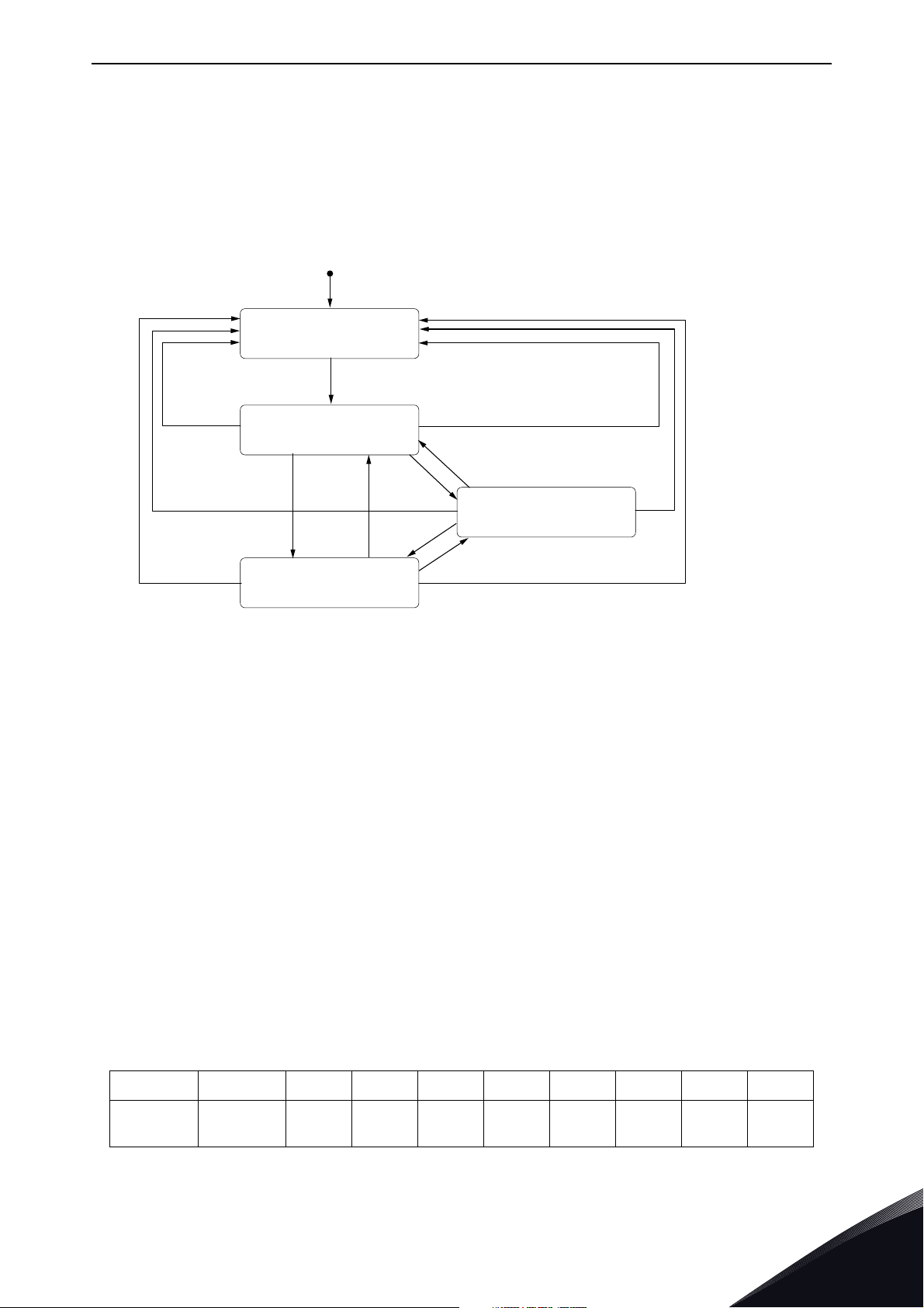
3. CANOPEN PROTOCOL DESCRIPTION
3.1 NMT
NMT network management manages CANopen, and is a mandatory, common feature for all
devices. The protocol describes several node control services and the state machine.
1 = When the power is on, the NMT state is entered autonomously
2= The NMT state initialisation is finished, the NMT pre-operational state is entered
automatically
3 = NMT service starts with remote node indication or by local control
4 and 7 = NMT service enters pre-operational indication
5 and 8 = NMT service stops remote node indication
6 = NMT service starts remote node indication
9, 10 and 11 = NMT resets node indication
12, 13 and 14 = Indication of NMT service reset communication
Boot-up protocol
After a node starts, it will enter automatically into the pre-operational state. Always when this
transition occurs, a boot-up message is sent into the bus.
Table 1: Boot-up message
CAN ID LENGTH DATA0 DATA1 DATA2 DATA3 DATA4 DATA 5 DATA 6 DATA7
Figure 1. NMT state machine
0x700 +
Node ID
Local contacts: http://drives.danfoss.com/danfoss-drives/local-contacts/
10
3
Page 10

vacon • 10 CANopen protocol description
3.2 Node control protocols
Protocol start remote node
The start remote node message sets the node(s) into operational state. See Figure 1. NMT state
machine. If the node ID in the message is set to ‘0’, the message affects all nodes (broadcast).
Table 2: Start remote node message
CAN ID LENGTH DATA0 DATA1 DATA2 DATA3 DATA4 DATA5 DATA6 DATA7
0x0 0x2 0x1
NODE
ID
Protocol stop remote node
The stop remote node message sets the node(s) into stopped state. See Figure 1 NMT state
machine. If the node ID in the message is set to ‘0’, the message affects all nodes (broadcast). When
the node is in stopped state, it will not answer to SDO or PDO messages.
Table 3: Stop remote node message
CAN ID LENGTH DATA0 DATA1 DATA2 DATA3 DATA4 DATA5 DATA6 DATA7
0x0 0x2 0x2
NODE
ID
Protocol enter pre-operational
The enter pre-operational message sets the node(s) into pre-operational state. See Figure 1. NMT
state machine. If the node ID in the message is set to ‘0’, the message affects all nodes (broadcast).
When the node is in pre-operational state, it will not answer to PDO messages.
Table 4: Enter pre-operational message
CAN ID LENGTH DATA0 DATA1 DATA2 DATA3 DATA4 DATA5 DATA6 DATA7
0x0 0x2 0x80
NODE
ID
Protocol reset node
The reset node message makes the node(s) apply application reset. See Figure 1. NMT state
machine. Application reset sets the whole object dictionary back to the default or previously saved
values. If the node ID in the message is set to ‘0’, the message affects all nodes (broadcast). After
the node has made the application reset, it will enter the pre-operational state automatically from
the initialising state. This also creates a boot-up event and the boot-up message is sent after the
reset.
Table 5: Reset node message
CAN ID LENGTH DATA0 DATA1 DATA2 DATA3 DATA4 DATA5 DATA6 DATA7
0x0 0x2 0x81
NODE
ID
3
Local contacts: http://drives.danfoss.com/danfoss-drives/local-contacts/
Page 11

CANopen protocol description vacon • 11
Protocol reset communication
The reset communication message makes the node(s) apply communication reset. See Figure 1.
NMT state machine. Communication reset does not affect the object dictionary values. If the node
ID in the message is set to ‘0’, the message affects all nodes (broadcast). After the node has made
the communication reset, it will enter the pre-operational state automatically from the initialising
state. This also creates a boot-up event and the boot-up message is sent after the reset.
Table 6: Reset communication message
CAN ID LENGTH DATA0 DATA1 DATA2 DATA3 DATA4 DATA5 DATA6 DATA7
0x0 0x2 0x82
NODE
ID
3.3 Error control protocols
It is not allowed to use guarding protocol and heartbeat protocol on one NMT slave at the same
time. If the heartbeat producer time is unequal 0, the heartbeat protocol is used.
3.3.1 Heartbeat protocol
Heartbeat protocol defines the producer and consumer. The producer node sends its NMT status
that is then available for any consumer node. The consumer node is the receiver of heartbeat
messages. The producer node has a timing parameter that indicates how often the heartbeat
message should be sent. The consumer node has a relative parameter that indicates how often the
heartbeat message should be received. If the consumer does not receive the heartbeat message
within the time defined in the heartbeat object entry, an error event occurs.
Table 7: Node status description
Value Description
0x0 Boot-up
0x4 Stopped
0x5 Operational
0x7F Pre-operational
Table 8: Heartbeat message
CAN ID LENGTH DATA0 DATA 1 DATA2 DATA3 DATA4 DATA 5 DATA6 D ATA7
0x700 +
Node ID
0x1 Status
Table 9: Heartbeat-related objects in OD
Index Description
0x1016 Consumer heartbeat time
0x1017 Producer heartbeat time
0x1029 Error behaviour
Local contacts: http://drives.danfoss.com/danfoss-drives/local-contacts/
3
Page 12

vacon • 12 CANopen protocol description
3.3.2 Node guarding protocol
Node guarding protocol is a NMT master driver protocol, where the master sends a remote
transmission request, which is answered by the slave. The slave response includes one data byte
that consists of a NMT slave state, and a toggle bit that toggles every response.
NOTE! The CiA application note 802 recommends that the node guarding protocol should not be
used, because of different handling of RTR frames in CAN controllers.
OPTE6 option board does not have a hardware-triggered automatic response to the RTR frame. RTR
information is handled by software, and the response data always consists of updated information.
Table 10: Node guarding RTR frame (remote request)
CAN ID LENGTH RTR DATA0 DATA1 DATA2 DATA3 DATA 4 DATA5 DATA6 DATA7
0x700 +
Node ID
Table 11: Node guarding response
CAN ID LENGTH DATA0 DATA1 DATA2 DATA3 DATA4 DATA5 DATA6 DATA7
0x700 +
Node ID
0x0 1
0x1 t Status
Table 12: Node guarding slave status
Status
Value Description
0x4 Stopped
0x5 Operational
0x7F Pre-operational
3
Table 13: Node guarding related objects in OD
Index Description
0x100C Guard time
0x100D Life time factor
3.3.3 EMCY object
Option board works as an EMCY producer. The EMCY object is transmitted when a fault occurs in
the drive or option board. To switch off the EMCY producer, disable the EMCY COB-id by writing MSB
to 1 (object 0x1014).
When an error occurs, the EMCY message is transmitted with the current value of the error
register and the error code is inserted into the pre-defined error field list. The newest error code is
Local contacts: http://drives.danfoss.com/danfoss-drives/local-contacts/
Page 13

CANopen protocol description vacon • 13
always the first sub-index on the error field list. When all active errors are cleared, an empty EMCY
object is transmitted.
If a drive-internal fault occurs, the MSEF field contains the drive fault code. See the application and
user manual for possible fault codes. The ER field holds a bit coded value of the error type. See
object 0x1001 for more details.
Table 14: EMCY message
CAN ID LENGTH DATA0 DATA1 DATA2 DATA3 DATA4 DATA5 DATA6 DATA7
0x80 +
Node ID
0x8 EEC ER MSEF
Table 15: EMCY message data fields
EEC Emergency error code
ER Error register value
MSEF
Manufacturer-specific
error code
Table 16: Used EMCY error codes and description MSEF fields
DATA0 DATA1 DATA2 DATA3 DATA4 DATA5 DATA6 DATA7
0x0000
0x1000 Drive fault codes
0x8110 -
0x8120 -
0x8130
ER
0x8140 -
3: N umb er of remai ning error s ource s
3: Heartbeat consumer subindex
4: Heartbeat consumer node-ID
0x8210 -
0x8220 -
0x8240 -
0x8250 -
Table 17: Description and behavior of different error situations
EEC Description Error behaviour Err LED
0x0000
0x1000
0x8120
0x8130
Error Reset or No Error
Generic Error
CAN in Error Passive
Mode
Life Guard Error
Heartbeat Error
If MSEF field is empty all error sources are cleared and drive
fault is cleared.
Drive fault codes have changed. -
EMCY is sent after CAN driver goes back to active state. This
also clears the fault.
Error is reset when a RTR is received or either of the life
guard objects (0x100C, 0x100D) is written to zero.
Error is reset when a HB message is received by the HB consumer, or the consumer entry is changed (either Node-ID or
Heartbeat Time).
Single flash
-
Double
flash
Local contacts: http://drives.danfoss.com/danfoss-drives/local-contacts/
3
Page 14

vacon • 14 CANopen protocol description
Table 17: Description and behavior of different error situations
0x8140 Recovered from Bus-Off
0x8250
PDO timer expired
EMCY is sent after CAN driver goes back to active state. This
also clears the fault.
Error is cleared when a PDO is received (in expired PDO).
On
Quadruple
flash
All communication errors are reset if a reset command is given. This does not however reset drive
faults if there are active error sources.
EMCYs are also created in some cases, even though a fault is not created. These are for notification
only.
Table 18: Notification EMCY objects
EEC Description
0x8110 CAN overrun (objects lost)
0x8210 PDO not processed due to length error
0x8220 PDO length exceeded
0x8240 Unexpected SYNC data length
Table 19: EMCY-relate objects in OD
Index Description
0x1001 Error register
0x1003
0x1014 EMCY object COB-ID
Pre-defined error field
list
3.4 SDO protocol
The Option board contains one SDO server. The SDO protocol provides a direct access to the object
entries of the object dictionary of the CANopen device. Each message is acknowledged by the
server. The protocol is mostly used to set and read parameters from the object dictionary at the
pre-operational state. Some objects have limitations for SDO usage at the operational state.
Up to four bytes can be transferred by using the expedited transfer, where the data fits into one CAN
message. For bigger than 4-byte object sizes, segmented transfer must be used. Optionally, block
transfer is also possible with bigger data types. Block transfer is most efficient with big data sizes.
Table 20: SDO-related objects in OD
Index Description
3
0x1200
SDO server parameter
object
Local contacts: http://drives.danfoss.com/danfoss-drives/local-contacts/
Page 15

CANopen protocol description vacon • 15
3.5 PDO protocol
Process data objects PDOs are used to transmit real-time data with no protocol overhead. Each
PDO has its mapping and communication parameter record.
There are two different types of PDOs. Transmit PDOs for producing data into network and Receive
PDOs for consuming data from network. OPTE6 board supports 3 receive and 3 transmit PDOs.
Table 21: PDO-related objects in OD
Index Description
0x1400 1st rxPDO communication parameter record
0x1401 2nd rxPDO communication parameter record
0x1402 3rd rxPDO communication parameter record
0x1600 1st rxPDO mapping parameter record
0x1601 2nd rxPDO mapping parameter record
0x1602 3rd rxPDO mapping parameter record
0x1800 1st txPDO communication parameter record
0x1801 2nd txPDO communication parameter record
0x1802 3rd txPDO communication parameter record
0x1A00 1st txPDO mapping parameter record
0x1A01 2nd txPDO mapping parameter record
0x1A02 3rd txPDO mapping parameter record
3.5.1 PDO communication parameter record
PDO communication parameter record defines the COB-id, transmission type and how often the
PDO is transmitted. The fields can be modified during the pre-operational state.
Table 22: PDO communication parameter record
Indexes Sub-index Name Data type RX PDO TX PDO
0 Highest sub-index supported UNSIGNED8 ro ro
1 COB ID UNSIGNED32 r/w r/w
0x1400
0x1401
0x1402
0x1800
0x1801
0x1802
2 Transmission type UNSIGNED8 r/w r/w
3 Inhibit time UNSIGNED16 ro r/w
4 Reserved UNSIGNED8 ro ro
5 Event timer UNSIGNED16 r/w r/w
6 SYNC start value UNSIGNED8
Local contacts: http://drives.danfoss.com/danfoss-drives/local-contacts/
Not
available
r/w
3
Page 16

vacon • 16 CANopen protocol description
3.5.2 COB ID
COB ID determines whether the PDO is valid (active) and using 11-bit or 29-bit frames.
Table 23: COB ID
31 30 29 28 11 10 0
Valid Reserved Frame
Table 24: COB ID data fields
Bit(s) Value Description
Valid
Reserved x Not applicable
Frame
29-bit CAN-ID x
11-bit CAN-ID x
0x00000 11-bit CAN-ID
29-bit CAN-ID
0 PDO exists / enabled
1
0 11-bit CAN-ID valid
1 20-bit CAN-ID valid
PDO does not exist /
disabled
29-bit CAN-ID of the CAN
extended frame
11-bit CAN-ID of the CAN
base frame
3
Local contacts: http://drives.danfoss.com/danfoss-drives/local-contacts/
Page 17

CANopen protocol description vacon • 17
3.5.3 Transmission type
Table 25: PDO transmission types
Value Description
0x00
0x01
0x02
0x03
0x04
... ...
0xF0
0xF1
... ... - -
0xFB
0xFC
0xFD
0xFE
Synchronous (acyclic)
Synchronous (cyclic every sync)
Synchronous (cyclic every 2nd sync)
Synchronous (cyclic every 3rd sync)
Synchronous (cyclic every 4th sync)
Synchronous (cyclic every 240th sync)
Reserved
Reserved
RTR-only (synchronous)
RTR-only (Event-driven)
Event-driven (manufacturer-specific)
Receive
PDO
XX
X
1
X
1
X
1
X
1
X
1
X
1
--
--
-X
-X
XX
Transmit
PDO
X
X
X
X
X
X
0xFF
For receive PDO, each sync transmission mode equals the same. Each sync always activates the latest
1
Event-driven (device and application profile)
XX
received PDO value.
Synchronous means that the PDO is transmitted after the SYNC. The CANopen device starts
sampling the data with the reception of the SYNC. If the transmission mode of the PDO is acyclic,
the CANopen device gives an internal event, the sampling starts with the next SYNC and the PDO is
transmitted afterwards. If the transmission mode is cyclic, the sampling starts with the reception
of every SYNC, every second SYNC, every third SYNC etc. depending on the given value, and the PDO
is transmitted afterwards.
RTR-only means that the PDO is requested via RTR. If the transmission mode of the PDO is
synchronous, the CANopen device starts sampling with the reception of every SYNC and will buffer
the PDO. If the mode is event-driven, the CANopen device starts the sampling with the reception of
the RTR and transmits the PDO immediately.
Event-driven means that the PDO can be transmitted at any time based on the occurrence of the
internal event of the CANopen device. An event that triggers the OPTE6 transmission occurs when
the data mapped into the PDO is changed. Also, an event timer can be used to create transmit
events.
Inhibit time
For transmit PDOs, the inhibit time defines the minimum transmission interval, when 0xFE or 0xFF
transmission types are selected. For receive PDOs, the inhibit time is disabled. The inhibit time is
16bit unsigned value that is given as multiple of 100μs. Zero value means that the inhibit time is
disabled.
Local contacts: http://drives.danfoss.com/danfoss-drives/local-contacts/
3
Page 18

vacon • 18 CANopen protocol description
Event timer
For a transmit PDO event, the timer defines the maximum interval between the transmissions, if
the transmission type is set to 0xFE or 0xFF.
For a receive PDO event, the timer activates the deadline monitoring. The deadline monitoring is
activated at the first received PDO. If the time between the after the last PDO received is longer
than defined in the event timer, a fault will occur.
Event timer is 16bit unsigned value that is given as multiple of 1ms. Zero value means that the event
timer is disabled.
Sync start value
Sync start value gives the possibility to compensate network peak traffic in case of sync
transmission mode. If the sync start value is zero, the normal sync behaviour for the PDO is used.
If the sync start value is greater than zero, the PDO waits for the SYNC message that contains the
counter value. When the counter value of a SYNC message equals the SYNC start value, the first
SYNC message is regarded as received. The sync start value must not be changed while the PDO
exists. See the SYNC message format in Table 29.
3.5.4 PDO parameter mapping record
Each PDO consists of a maximum of 8 bytes of mapped data. To data map the PDO, use a
corresponding mapping record that consists of index, sub-index and the length of the mapped
object.
Table 26: PDO mapping structure
31 16 15 8 7 0
Index Sub-index Length
Table 27: PDO mapping parameter record
Indexes Sub-index Name Data type Access
0x1600
0x1601
0x1602
0x1A00
0x1A01
0x1A02
0
1
2
3
4
Number of mapped objects in
PDO
1st object to be mapped UNSIGNED32 r/w
2nd object to be mapped UNSIGNED32 r/w
3rd object to be mapped UNSIGNED32 r/w
4th object to be mapped UNSIGNED32 r/w
UNSIGNED8 r/w
3
Local contacts: http://drives.danfoss.com/danfoss-drives/local-contacts/
Page 19

CANopen protocol description vacon • 19
To data map the PDOs, first disable the related PDO COB ID in the pre-operational state. In the
mapping structure, write the sub-index 0 to zero (number of mapped objects). Then write the
mapping structures on the mapping parameter record, starting from the sub-index 1. When you
have written all the necessary structures, write the sub-index 0 to correspond to the mapped
objects.
Example on how to write a dummy object to RPDO1 4th entry (when using Bypass mode) is explained
below:
Table 28. RPDO mapping example
Transfer data (hex) Interpretation
23 00 14 01
2F 00 16 00
23 00 16 04
2F 00 16 00
23 00 14 01
01 02 00 80 Write RPDO1 COB-ID (1400:01) to invalid (0x8000 0201)
00 00 00 00 Write RPDO1 mapping number of entries (1600:00) to 0
10 00 06 00
Write RPDO1 4
th
entry (1600:04) to Dummy object (00060010)
04 00 00 00 Write RPDO1 mapping number of entries (1600:00) to 4
01 02 00 00 Write RPDO1 COB-ID (1400:01) as valid (0x201)
3.6 SYNC protocol
Sync protocol is used by PDOs when the transmission is synchronous. The sync object that is
defined by COB ID in the object 0x1005 triggers the transmission of the txPDOs, or activates the
previously received data of the rxPDO. At the default sync message the CAN-ID is 0x80. The sync
message is a zero-length message but optionally it can consist of an 8bit counter.
Table 29: SYNC message
CAN ID LENGTH
0x80 0x0
Table 30: SYNC message with counter
CAN ID LENGTH DATA0
0x80 0x1 Counter
3.6.1 SYNC with counter
When a counter is used in a sync message, the PDOs that have a defined sync start value compare
the value against the sync message counter. The sync producer counter will overflow after it
reaches the value defined in its ‘synchronous counter overflow value’ at the object 0x1019. Also, the
sync consumer has the object 0x1019 even when the value itself is ignored. When the value of the
sync consumer is greater than zero, the sync counter handling and expecting of the sync messages
with counter are activated.
When the sync start value and the sync counter value match, the first sync message is regarded as
received.
The following figure shows an example of SYNC messaging, when the slave is configured with:
• 0x1019 - Synchronous counter 128
• 0x1800,2 - Transmission type = 2 (Cyclic, No. of SYNCs = 2)
• 0x1800,6 - Sync start value = 4
Local contacts: http://drives.danfoss.com/danfoss-drives/local-contacts/
3
Page 20

vacon • 20 CANopen protocol description
(1) (2) (3) (4) (5) (6) (7) (8)
SYNC
time
txPDO
Figure 2. txPDO responses to SYNC messages
Table 31: Sync-related object in OD
Index Description
0x1005 COB ID SYNC
0x1019 Synchronous counter
0x1014 EMCY object COB ID
0x1400 1st rxPDO communication parameter record
0x1401 2nd rxPDO communication parameter record
0x1402 3rd rxPDO communication parameter record
0x1800 1st txPDO mapping parameter record
0x1801 2nd txPDO mapping parameter record
0x1802 3rd txPDO mapping parameter record
3
Local contacts: http://drives.danfoss.com/danfoss-drives/local-contacts/
Page 21

CANopen protocol description vacon • 21
3.7 Communication objects
3.7.1 0X1000 - Device Type
The device type object indicates basic information about the device, including the supported device
profile and the profile settings.
Table 32: 0x1000 Device type
Index Sub-index Value Name Data type Access
0x1000 - 0x00010192 Device type UNSIGNED32 const
Value description:
0x0192 = 402 (Drive profile)
0x0001 = AC drive with PDO set for a generic drive device
3.7.2 0X1001 - Error Register
Error register indicates the active error code.
Table 33: 0x1001 Error register
Index Sub-index Value Name Data type Access
0x1001 - 0x0 Error register UNSIGNED8 ro
Table 34: Error register bit descriptions
Bit Meaning
0 Generic error
1Current
2Voltage
3Temperature
4 Communication error (overrun, error state)
5 Device profile-specific*
6Reserved*
7 Manufacturer-specific*
* Not used/supported
Local contacts: http://drives.danfoss.com/danfoss-drives/local-contacts/
3
Page 22

vacon • 22 CANopen protocol description
3.7.3 0X1003 - Pre-defined Error Field
Pre-defined error field is a list of errors signaled with an EMCY object, listing the error history of
up to 9 error entries. Sub-index 1 contains the latest error.
Table 35: 0x1003 Pre-defined error field
Index Sub-index Value Name Data type Access
00x0
10x0
0x1003
.. .. .. .. ..
90x0
Number of
errors
Sta ndard error
field
Sta ndard error
field
UNSIGNED8 ro
UNSIGNED32
UNSIGNED32
ro
ro
3.7.4 0X1005 - COB ID SYNC
Defines the synchronisation message COB ID. Receiving the sync message causes actions in the
PDOs that have a synchronous transmission mode.
Table 36: 0x1005 COB ID sync
Index Sub-index Value Name Data type Access
0x1005 - 0x00000080 COB ID sync UNSIGNED32 r/w
3.7.5 0X100C - Guard Time
The object contains the guard time in milliseconds. As a default, guarding is disabled.
Table 37: 0x100C Guard time
Index Sub-index Value Name Data type Access
0x100C - 0x0000 Guard time UNSIGNED16 r/w
3.7.6 0X100D - Life Time Factor
Life time factor is used together with guard time, which is multiplied with the life time factor.
Table 38: 0x100D Guard time
Index Sub-index Value Name Data type Access
0x100D - 0x00 Guard time UNSIGNED8 r/w
Node life time = life time factor x guard time. If node life time is zero, guarding is disabled.
3
Local contacts: http://drives.danfoss.com/danfoss-drives/local-contacts/
Page 23

CANopen protocol description vacon • 23
3.7.7 0X1014 - COB ID EMCY
The object defines the emergency message COB ID.
Table 39: 0x1014 COB ID EMCY
Index Sub-index Value Name Data type Access
0x1014 -
0x00000080+
node id
COB ID EMCY UNSIGNED32 r/w
Setting MSB (bit 31) to 1 will disable sending of EMCY messages.
3.7.8 0X1016 - Heartbeat Consumer Entries
The device can act as the heartbeat consumer. Up to 8 devices can be monitored, as defined in the
table below. If the heartbeat transmission delay of a defined node ID exceeds the heartbeat time,
the error behaviour is activated according to the error behaviour object.
Table 40: 0x1016 Heartbeat consumer entries
Index Sub-index Value Name Data type Access
0 0x08 Number of entries UNSIGNED8 ro
1 0x0000 0000
2 0x0000 0000
3 0x0000 0000
Consumer heart beat
time 1
Consumer heart beat
time 2
Consumer heart beat
time 3
UNSIGNED32 r/w
UNSIGNED32 r/w
UNSIGNED32 r/w
Consumer heart beat
time 4
Consumer heart beat
time 5
Consumer heart beat
time 6
Consumer heart beat
time 7
Consumer heart beat
time 8
UNSIGNED32 r/w
UNSIGNED32 r/w
UNSIGNED32 r/w
UNSIGNED32 r/w
UNSIGNED32 r/w
0x1016
4 0x0000 0000
5 0x0000 0000
6 0x0000 0000
7 0x0000 0000
8 0x0000 0000
Table 41: Consumer heartbeat time entry
31 24 23 16 15 0
Not used, must be
zeroes.
Node ID Heartbeat time
Local contacts: http://drives.danfoss.com/danfoss-drives/local-contacts/
3
Page 24

vacon • 24 CANopen protocol description
3.7.9 0X1017 - Producer Heartbeat Time
Heartbeat producer object consists of the time in milliseconds (ms) that it takes to transmit the
heartbeat message into the network. If the value is zero, the heartbeat is not used.
Table 42: 0x1017 Producer heartbeat time
Index Sub-index Value Name Data type Access
0x1017 - 0x0000
Table 43: Heartbeat message
CAN ID LENGTH DATA0
0x700 + node 0x1 Node state
Producer
heartbeat time
UNSIGNED16 r/w
3.7.10 0X1018 - Identify Object
The object gives information about the option board
Table 44: 0x1018 Identify object
Index Sub-index Value Name Data type Access
0 0x04 Number of entries UNSIGNED8 ro
1 0x90 Vendor ID UNSIGNED32 ro
0x1018
2 - Product code UNSIGNED32 ro
3 - Revision number UNSIGNED32 ro
4 - Serial number UNSIGNED32 ro
3.7.11 0X1019 - Synchronous counter overflow value
The synchronous counter overflow value defines whether a counter is mapped into the SYNC message, as well as the highest value the counter can reach. 0 disables the sync counter.
Table 45: 0x1019 Synchronous counter
Index Sub-index Value Name Data type Access
0x1019 - 0x00
Synchronous
counter
UNSIGNED8 r/w
3
Local contacts: http://drives.danfoss.com/danfoss-drives/local-contacts/
Page 25

CANopen protocol description vacon • 25
3.7.12 0X1029 - Error behaviour
Error behaviour allows a change in the default error behaviour if there is a communication
error.
Table 46: 0x1029 Error behaviour
Index Sub-index Value Name Data type Access Min Max
0 0x01 Number of entries UNSIGNED8 ro 2 2
0x1029
1 0x00 Communication error UNSIGNED8 r/w 0 2
2 0x01 Internal error UNSIGNED8 r/w 1 1
Table 47: Error behaviour
Value Description
0 Pre-operational
1 No change in state
2 Stopped
3..127 Reserved
3.8 Saving and restoring the object dictionary
CANopen defines a way of restoring the values in an object dictionary to the defaults and saving the
values if the modified values must be valid after the power cycle. The manufacturer-specific bypass
configuration can be restored to the object dictionary.
3.8.1 0X1010 Store parameter field
To save the object dictionary, use the object 0x1010 ‘Store Parameter Field’.
The option board only saves the parameters in the object dictionary with a command. Autonomous
saving is not supported. To save the parameters in the object dictionary, write the value 0x65766173
(ASCII “save”) into the sub-index by using the SDO protocol.
Table 48: 0x1010 Store parameter field
Index Sub-index Name Data type Access
0x1010
0
1 Save all parameters UNSIGNED32 r/w
Highest sub-index
supported
UNSIGNED8 ro
3.8.2 0X1011 Restore default parameters
The object values of the object dictionary are restored to defaults by using the object 0x1011. Option
board supports restoring All parameters (sub index 1) and manufacturer-specific Bypass mode defaults (sub index 4).
Local contacts: http://drives.danfoss.com/danfoss-drives/local-contacts/
3
Page 26

vacon • 26 CANopen protocol description
To restore parameters, write 0x64616F6C (ASCII "load") into the sub-index by using the SDO
protocol. Default object values are selected after reset. Restore all default parameter restores CiA402 default parameters (refer to Chapter 8.2.2.2). Bypass parameter set is described in Chapter 8.3.
Table 49: 0x1011 Restore default parameters
Index Sub-index Name Data type Access
0 Highest sub-index supported UNSIGNED8 ro
Restore all default
parameters
Restore bypass parameter
set*
Restore Puller parameter
set
Restore Co-Extruder parameter set
UNSIGNED32 r/w
UNSIGNED32
UNSIGNED32
UNSIGNED32
r/w
r/w
r/w
0x1011
1
4
5
6
* The bypassed set disables the CIA- 402 drive profile and resets the PDO mapping to the vendor specific
configuration. See Chapter 8.2 and Chapter 8.3 for more information.
3
Local contacts: http://drives.danfoss.com/danfoss-drives/local-contacts/
Page 27

CANopen option board OPTE6 - technical data vacon • 27
4. CANOPEN OPTION BOARD OPTE6 - TECHNICAL DATA
4.1 General
Table 50. Technical data of CANopen opt ion board
CAN bus electrical
isolation
Ambient
temperature
Storing temperature As specified in drive specification (-40°C … 70°C)
Humidity 0-95%, non-condensing, corrosive
Vibration and
electrical safety
Emission C2 level, EN 61800-3 (2004)
Immunity C2 level, EN 61800-3 (2004)
CAN Interface
500 VDC
As specified in drive specification (-10°C … 40°C)
EN 61800-5-1 (2007)
5… 15.8 Hz 1mm (peak)
15.8 ...150 Hz 1 G
Isolation
Protection
2500 V rms isolation with a less than
10-ns propagation delay
±8kV ESD IEC 61000-4-2 Contact
Discharge
±80V Fault Protection
greater than ±12V common Mode Range
4.2 CAN cable
The recommended cables for installations are 4 wires twisted and a shielded cable with an
impedance of 120 Ohm. The network topology is a 2-wire bus line that is terminated at both ends by
resistors representing the characteristic impedance of the bus line. The typical CAN cable
impedance is 120 Ohm, and so for the termination resistors of ~120 Ohm must be used. For long
networks a higher resistor value must be used (150-300 Ohm).
Table 51. Bus parameter relation to cable length
Cable length Max bit rate [kbit/s]
0-40 m 1000 Max 70
100 m 500
500 m 100
1 km 50
Max cable resistance
[m
Ω/m]
<60
<40
<26
Local contacts: http://drives.danfoss.com/danfoss-drives/local-contacts/
4
Page 28
vacon • 28 CANopen option board OPTE6 - technical
E6 Option Board E6 Option Board E6 Option Board
9384.emf
E6 Option Board E6 Option Board Non isolated node
9385.emf
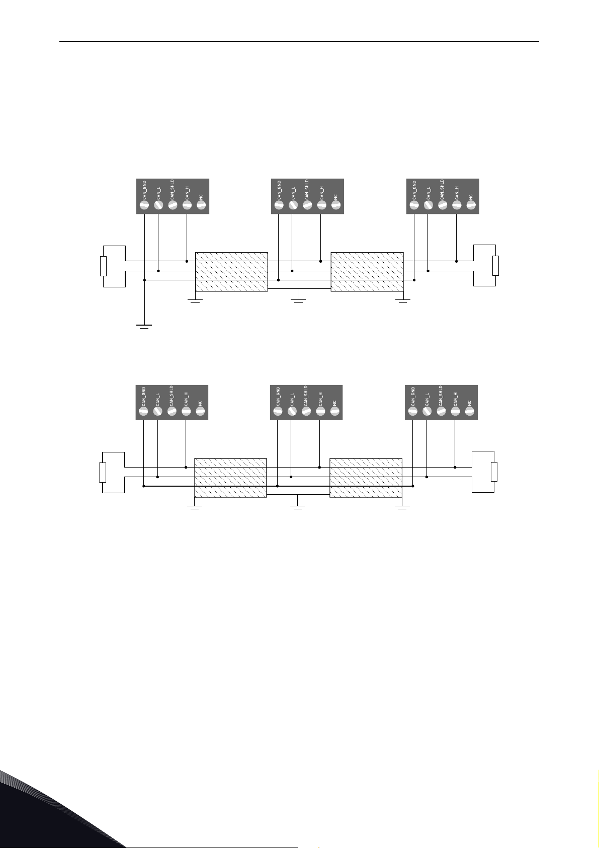
4.2.1 Isolated ground connection
The OPTE6 option board is galvanically isolated. In CANopen networks that are completely galvanically isolated the CAN ground signal is carried in the cable line. It is connected at only one point
into common ground potential. If one CAN device with not galvanically isolated interface is connected to the network, the potential for isolated CAN ground is given. Therefore only one device with not
galvanically isolated interface may be connected to the network.
Figure 3. Completely isolated nodes
Figure 4. CAN network with one non-isolated node
Local contacts: http://drives.danfoss.com/danfoss-drives/local-contacts/
4
Page 29

CANopen option board OPTE6 - technical data vacon • 29
4.2.2 Recommended cable
For all OPTE6 installations the use of 4-wire cable is recommended. 4 wires enable the connection
of isolated digital grounds with nodes.
VACON
UNITRONIC
Colour-coded in accordance with DIN 47100
Table 52. Cable thickness, length and baud rate relation
®
recommends the following cable:
®
BUS CAN FD P
Figure 5. Recommended cable
Bit rate Min cable thickness
1 Mbit/s 0.25
500 kbit/s 0.25 0.34
250 kbit/s 0.25 0.34 0.6
125 kbit/s 0.25 0.34 0.6
100 kbit/s 0.25 0.34 0.6 0.6
50 kbit/s 0.25 0.34 0.6 0.6
Cable
length
25 100 250 500
Local contacts: http://drives.danfoss.com/danfoss-drives/local-contacts/
4
Page 30
vacon • 30 OPTE6 layout and connections
M/N A N/M
1
2
3
4
5
6
7
product code
serial no.
9338A_00
Pin 1
Pin 5
9340.emf
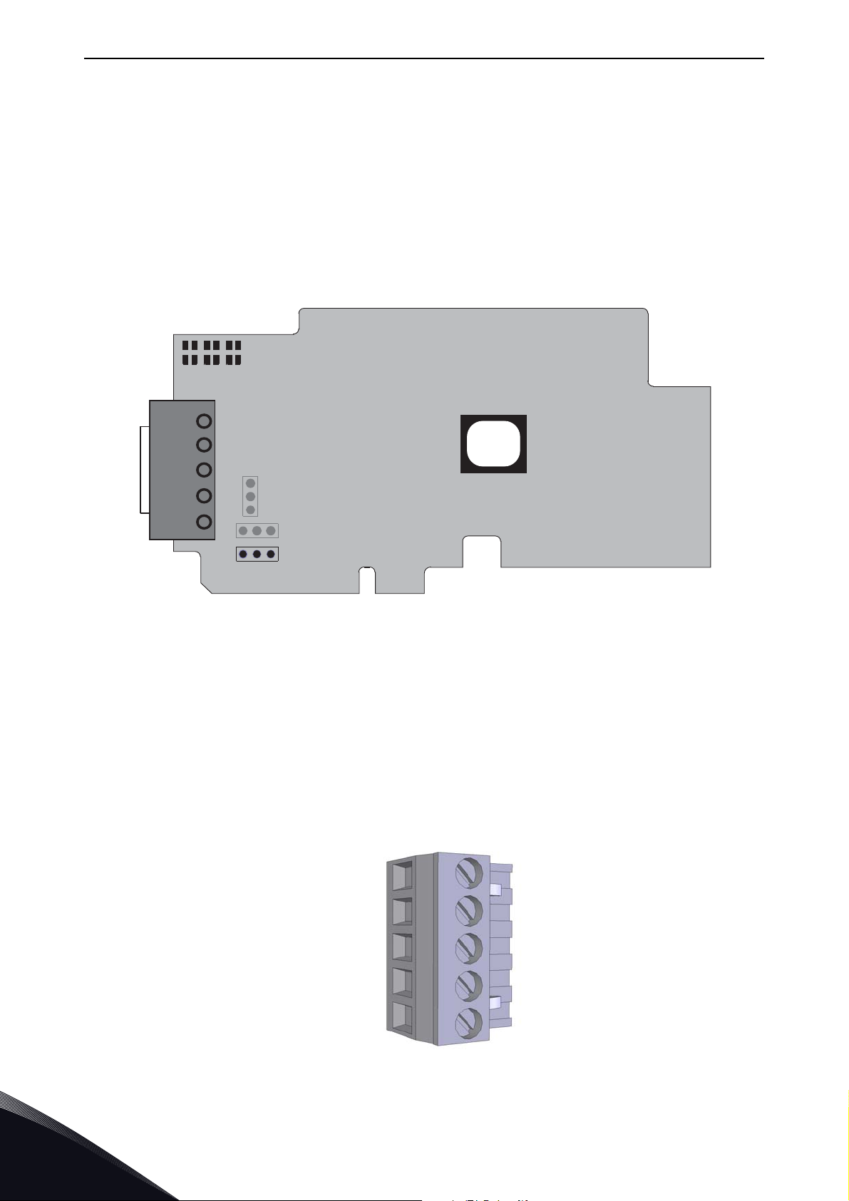
5. OPTE6 LAYOUT AND CONNECTIONS
5.1 Layout and connections
OPTE6 has two different hardware revisions with slightly different layout. Layout is different in LED
arrangement and termination resistor orientation.
The two hardware revisions are marked with different product codes, and this product code can be
located from the sticker on the top side (location marked in Figure 6).
The two hardware revisions are named 70CVB01605 and 70CVB01124.
1 = CAN GND (isolated digital ground reference)
2 = CAN L
3 = SHIELD (shield connector)
4 = CAN H
5 = NC (No connection)
6 = Grounding option jumper
7= Bus termination resistor
5
Figure 6. OPTE6 board layout
Figure 7. CAN connector
Local contacts: http://drives.danfoss.com/danfoss-drives/local-contacts/
Page 31

OPTE6 layout and connections vacon • 31
CAN connector pinout
Pin out
1 CAN GND, isolated digital ground reference
2CAN LO
3 Shield connector
4CAN HI
5 No connection
Local contacts: http://drives.danfoss.com/danfoss-drives/local-contacts/
5
Page 32

vacon • 32 OPTE6 layout and connections
9339A_00
N A MM A N
70CVB01605 70CVB01124
5.2 LED Indications
Figure 8. LED indicators
M = CANopen run led
A = CANopen err led
N = Board status
CANopen run led (green)
LED is Description
Blinking The CANopen device is in the pre-operational state.
Single flash The CANopen device is in the stopped state.
ON The CANopen device is in the operational state.
CANopen err led (red)
LED is Description
OFF No error
Blinking Invalid configuration
Single flash
Double flash
Quadruple flash
ON The CAN controller is bus-off.
Board status led (green)
LED is Description
At least one of the error counters of the CAN controller has
reached or exceeded the warning level (too many error frames).
A guard event (NMT slave or NMT master) or a heartbeat event
(heartbeat consumer) has occurred.
An expected PDO was not received before the event timer
elapsed.
OFF Option board is not activated.
ON
Blinking (once/
1s)
Option board is in initialization state, waiting activation com-
mand from the AC drive.
Option board is activated and in RUN state. Option board is
ready for external communication.
Local contacts: http://drives.danfoss.com/danfoss-drives/local-contacts/
5
Page 33

OPTE6 layout and connections vacon • 33
3
1
2
3
2
1
1
2
3
A
B
C
9341A_00
70CVB0112470CVB01605
3
1
2
3
2
1
1
2
3
A
B
C
5.3 Jumpers
The termination resistor jumper location differs on used hardware version. The jumper locations
can be seen from figure below.
3
4
5
3
4
7
5
7
6
70CVB01605 70CVB01124
Figure 9. Jumper locations
The jumper (7) settings for the CAN bus termination resistor are shown in the figure below.
6
11653_00
Figure 10. CAN bus termination jumper
A = Termination resistor 120 Ohm connected
B = Termination resistor is not connected to the CAN bus. (Factory default setting)
C = Termination resistor is not connected to the CAN bus
The jumper (6) settings for the CAN cable shield grounding are shown in the figure below.
Local contacts: http://drives.danfoss.com/danfoss-drives/local-contacts/
5
Page 34

vacon • 34 OPTE6 layout and connections
3
1
2
3
2
1
1
2
3
A
B
C
9342.emf
Figure 11. CAN shield grounding option
A = CAN connector pin 3 (shield) connected to the drive chassis with a high-impedance RC circuit.
Recommended option when equipotential bonding is poor.
B = CAN connector pin 3 (shield) connected directly into the drive chassis. Recommended option
when equipotential bonding is good. (Factory default setting)
C = CAN connector pin 3 is not connected.
Local contacts: http://drives.danfoss.com/danfoss-drives/local-contacts/
5
Page 35

Installation vacon • 35
M4x55
9174.emf
DANGER
6. INSTALLATION
6.1 Installation in VACON® 100
Open the cover of the AC drive.
1
The relay outputs and other I/O-terminals may have a dangerous control voltage
present even when AC drive is disconnected from mains.
Local contacts: http://drives.danfoss.com/danfoss-drives/local-contacts/
6
Page 36

vacon • 36 Installation
3023.emf
DE
3024.emf
Open the inner cover to reveal the option board slots (C,D,E). See Figure below.
2
3
Install the fieldbus board into slot D or E. See figure below.
NOTE: Incompatible boards cannot be installed on the AC drive. Compatible
boards have a slot coding
that enable the placing of the board.
6
Local contacts: http://drives.danfoss.com/danfoss-drives/local-contacts/
Page 37

Installation vacon • 37
10
5
6.2 Prepare for use through fieldbus
Strip about 15 mm of the fieldbus cable (see specification in ch. 3.2) and cut off
the grey cable shield. Remember to do this for both bus cables (except for the
last device).
Leave no more than 10 mm of the cable outside the terminal block and strip the
cables at about 5 mm to fit in the terminals. See picture below.
4
5
Also strip the cable now at such a distance from the terminal that you can fix it to
the frame with the grounding clamp. Strip the cable at a maximum length of 15
mm. Do not strip the aluminum cable shield!
Then connect the cable to its appropriate terminals on the OPTE6 CANopen
option board terminal block.
Local contacts: http://drives.danfoss.com/danfoss-drives/local-contacts/
6
Page 38

vacon • 38 Installation
Cable clamp
Using the cable clamp included in the delivery of the drive, ground the shield of
the CAN cable to the frame of the AC drive.
NOTE: This can be done in all drives if there is no difference in PE potential
between the drives. However, if there is PE potential difference then the shield
should be connected to PE only at one point in the system. The shields of the
cables shall be joint but not connected to several PE points with different potential.
6
7
8
If the AC drive is the last device on the bus, the bus termination must be set
with jumper X13 (see ch. 4.3.)
Unless already done for the other control cables,
cut free the opening on the AC drive cover for the
fieldbus cable (protection class IP21).
NOTE: Cut the opening on the same side you
have installed the board in!
6
Local contacts: http://drives.danfoss.com/danfoss-drives/local-contacts/
Page 39

Installation vacon • 39
9202.emf
Fieldbus
cables
Fieldbus cable
= Bus termination
Termination
activated
Ter min ation
activated with
jumper
Termination
deactivated
Vacon 100 Vacon 100 Vacon 100 Vacon 100 Vacon 100
3007.emf
Remount the AC drive cover and run the cable as
shown in picture.
NOTE: When planning the cable runs, remember
to keep the distance between the fieldbus cable
and the motor cable at a minimum of 30 cm. It is
recommended to route the option board cables
away from the power cables as shown in the picture.
9
The bus termination must be set for the first and the last device of the fieldbus
line. See picture below. See also step 7 on page 38. We recommend that the first
device on the bus and, thus, terminated was the Master device.
10
Local contacts: http://drives.danfoss.com/danfoss-drives/local-contacts/
6
Page 40

vacon • 40 Installation
11649_00
11556A_0
6.3 Installation in VACON® 20
6.3.1 Frames MI1, MI2, MI3
Remove the cable connector lid from the
AC drive.
1
11555A_00
2
3
Select a correct grounding plate and attach it to the
option board mounting frame. The grounding plate is
marked with the supported enclosure size.
Attach an option board mounting frame to
the AC drive.
6
Local contacts: http://drives.danfoss.com/danfoss-drives/local-contacts/
Page 41

Installation vacon • 41
11559A_00
Connect the flat cable from the option board mounting frame to VACON® 20.
4
11557A_00
If a cable strain relief is required, attach the parts as shown in the figure.
5
6
11558A_00
Install the option board to the option board
holder. Make sure that the option board is
securely fastened.
Local contacts: http://drives.danfoss.com/danfoss-drives/local-contacts/
6
Page 42

vacon • 42 Installation
11560A_00
Cut free a sufficiently wide opening for the
option board connector.
7
11650_00
Attach the option board cover to VACON®
20. Attach the strain relief cable clamp with
screws if needed.
8
6
Local contacts: http://drives.danfoss.com/danfoss-drives/local-contacts/
Page 43

Installation vacon • 43
13006.emf
11562_00
11563_00
6.3.2 Frames MI4, MI5
®
Make sure power is disconnected before opening the VACON
1a: For MI4: Open the cover.
20 cover.
11561_00
1
2
1b: For MI5: Open the cover and release the fan connector.
Attach the option board support.
Local contacts: http://drives.danfoss.com/danfoss-drives/local-contacts/
6
Page 44

vacon • 44 Installation
11564_00
11565_00
Connect the flex cable to option board connector PCB.
3
Connect the option board to connector PCB.
4
5
Attach the option board with connector PCB to VACON® 20 and connect the flex
cable.
11566_00
6
Local contacts: http://drives.danfoss.com/danfoss-drives/local-contacts/
Page 45

Installation vacon • 45
MI 04
MI 05
11567_00
11568_00
Attach a suitable grounding plate to VACON® 20. The grounding plate is marked
with supported enclosure size.
6
Assemble a clamp on top of the grounding plate on both sides of the option board.
7
Local contacts: http://drives.danfoss.com/danfoss-drives/local-contacts/
6
Page 46

vacon • 46 Installation
11569_00
11570_00
8a: For MI4: Close the cover.
8
8b: For MI5: Remount the fan connector and close the cover.
6
Local contacts: http://drives.danfoss.com/danfoss-drives/local-contacts/
Page 47

Installation vacon • 47
13006.emf
13006.emf
6.4 Installation in VACON® 20 X and 20 CP
Do not add or replace option boards or fieldbus boards on an AC
drive with the power switched on. This may damage the boards.
Open the cover of the drive.
1
11643_00
MU3 example
The relay outputs and other I/O-terminals may have a dangerous control voltage
present even when the drive is disconnected from mains.
Local contacts: http://drives.danfoss.com/danfoss-drives/local-contacts/
6
Page 48

vacon • 48 Installation
7089_00
7090_00
7091_007091_00
Remove the option slot cover.
2
Install the option board into the slot as shown in the figure.
3
4
Mount the option slot cover. Remove the plastic opening for the option board terminals.
6
Local contacts: http://drives.danfoss.com/danfoss-drives/local-contacts/
Page 49

Installation vacon • 49
11638_00
6.5 Installation in VACON® 100 X (Frames MM4-MM6)
Open the cover of the AC drive.
1
Local contacts: http://drives.danfoss.com/danfoss-drives/local-contacts/
6
Page 50

vacon • 50 Installation
11639_00
To get access to the option board slots, remove the screws and open the cover of
the control unit.
2
6
Local contacts: http://drives.danfoss.com/danfoss-drives/local-contacts/
Page 51

Installation vacon • 51
11641_00
Install the option board into the correct slot, D or E.
DE
3
4
5
11640_00
Close the option board cover.
Remove the cable entry plate. If you
installed the option board in the slot
D, use the cable entry plate on the
right side. If you installed the option
board in the slot E, use the cable entry plate on the left side.
NOTE! The cable entry plate at the
bottom of the drive is used only for
mains and motor cables.
Local contacts: http://drives.danfoss.com/danfoss-drives/local-contacts/
6
Page 52

vacon • 52 Installation
6
7
Open the necessary holes in the cable entry plate. Do not open the other holes.
See the VACON
Attach a cable gland on the hole in the cable entry plate. Pull the fieldbus cable
through the hole.
NOTE! The fieldbus cable must go through
the correct cable entry plate to avoid going
near the motor cable.
®
100 X Installation Manual for the dimensions of the holes.
11642_00
8
9
Put the cable entry plate back.
Close the cover of the AC drive.
6
Local contacts: http://drives.danfoss.com/danfoss-drives/local-contacts/
Page 53

Commissioning vacon • 53
7. COMMISSIONING
This chapter describes how to commission the OPTE6 board for use. For instructions on how to setup the AC drive to be controlled over fieldbus, refer to Chapter 11 Appendix B - Fieldbus parametrization.
7.1 OPTE6 panel parameters
Different number of panel parameters are visible depending on the used AC drive and version. VA-
®
CON
20 family option board parameters are under SYS menu.
Table 53. OPTE6 board basic parameters
Panel code
#
VACON® 100
family
VACON® 20
family
Parameter Min Max Default Description
1 P5.x.3.1 P2.2 Node ID 1 127 1
2 P5.x.3.2 P2.3 Baud Rate 3 8 5
3 P5.x.3.3 P2.4 Operate Mode 1 4 1
5 P5.x.3.4* -
6 P5.x.3.5* -
7 P5.x.3.6* - Mode 0 1 0 Set OPTE6 mode. See Table 56
* From version V26 (INDUSTRIAL) and V18 (FLOW)
Table 54. OPTE6 Baud Rate settings
Comm.
Timeout
Restore from
Set
0 65535 1
01 0
Network-wide unique identifier
for each CANopen device
Data signalling rate. Should be
the same on each node in the
same bus. See Table 54
Selection between OPTE6 operate
modes. See Table 55
Timeout in seconds for CAN
communication faults (PASSIVE,
BUS-OFF)
0'1 All CANopen parameters are
reset to default values based on
Operate Mode.
Value Bit rate
1 10 kbps (not supported)
2 20 kbps (not supported)
3 50 kbps
4100 kbps
5125 kbps
6250 kbps
7500 kbps
8 1000 kbps
Table 55. OPTE6 Operate Mode settings
Value Name Description
1 Drive Profile CiA-402 drive profile, velocity mode active
Local contacts: http://drives.danfoss.com/danfoss-drives/local-contacts/
7
Page 54

vacon • 54 Commissioning
Table 55. OPTE6 Operate Mode settings
Value Name Description
2Bypass
3Puller*
4 Co-Extruder*
*Restricted availability, requires use of special application
VACON
CiA-420 EUROMAP profile, puller mode
active
CiA-420 EUROMAP profile, co-extruder
mode active
®
specific bypass mode active
Baud Rate: used in CANopen communication. Regardless of the selected bitrate, the bit sample
timing is set as close as possible to 87.5 % according to the CANopen specification.
Operate Mode: is used to change the modes of operation between standardized profile modes and
VACON
®
specific Bypass mode.
Different operate modes activate different device profile segment objects. Accessing e.g. CiA-402
velocity profile objects in Bypass mode is not possible. See Chapter 8.2 Velocity mode and Chapter
8.3 Bypass mode.
Comm. Timeout: Fieldbus communication timeout is time in seconds after a fault is created from
CAN bus communication errors (PASSIVE, BUS-OFF). Setting this value to 0 disables CAN bus errors from triggering a fault in AC drive. This does not affect other CANopen faults, e.g. heartbeat
consumer times. This value is the same as object 0x2004 - Communication timeout. See conditions
when fieldbus communication timeout is activated in Chapter 9.2 Fieldbus timeout fault (F53).
Table 56. OPTE6 Mode settings
Value Description Details
0Normal
Anyparameter service behaves same
®
1Pre V008
as version 7 and earlier in VACON
100 family devices. See Chapter 8.5 for
more details.
Mode: compatibility mode(s) can be activated using this parameter. This parameter is the same as
object 0x2005 - Mode.
7.1.1 OPTE6 additional panel parameters
®
From VACON
100 (INDUSTRIAL V027 and FLOW V018) and OPTE6 V009 firmware version forwards,
CANopen bus communication parameters are stored and can also be modified directly from panel
parameters. The stored parameters are modifiable and stored under the "Parameters" menu and
these parameters are restored after power cycle. The active settings are visible under the "Monitor"
menu.
These parameters are separated into sub-folders for easier modification. It is recommended to use
VACON
®
Live PC-tool to modify the parameters.
General Heartbeat RPDO1 Communication RPDO2 Communication
7
Local contacts: http://drives.danfoss.com/danfoss-drives/local-contacts/
Page 55

Commissioning vacon • 55
Table 57. OPTE6 board CANopen object parameters under General folder
Panel Code
VACON® 100
5.x.3.6.1 COB-ID SYNC 0x80 3.7.4
5.x.3.6.2 Guard Time 0 3.7.5
5.x.3.6.3 Life Time Factor 0 3.7.6
5.x.3.6.4 COB-ID EMCY 0x80 + Node ID 3.7.7
5.x.3.6.5 Sync Counter Ovf. 0 3.7.11
5.x.3.6.6 Error Behaviour 0 3.7.12
5.x.3.7.1 Producer Time 0 3.7.9
5.x.3.7. Consumer Time 1 0
5.x.3.7.3 Consumer Time 2 0
5.x.3.7.4 Consumer Time 3 0
5.x.3.7.5 Consumer Time 4 0
5.x.3.7.6 Consumer Time 5 0
5.x.3.7.7 Consumer Time 6 0
5.x.3.7.8 Consumer Time 7 0
Parameter Default Reference
3.7.8
5.x.3.7.9 Consumer Time 8 0
5.x.3.8.1 COB-ID 0x200 + Node ID 3.5.2
5.x.3.8.2 Transmission Type 0xFE
3.5.35.x.3.8.3 Inhibit Time 0
5.x.3.8.4 Event Timer 0
5.x.3.9.1 COB-ID 0x80000300 + Node ID 3.5.2
5.x.3.9.2 Transmission Type 0xFE
3.5.35.x.3.9.3 Inhibit Time 0
5.x.3.9.4 Event Timer 0
5.x.3.10.1 COB-ID 0x80000400 + Node ID 3.5.2
5.x.3.10.2 Transmission Type 0xFE
3.5.35.x.3.10.3 Inhibit Time 0
5.x.3.10.4 Event Timer 0
5.x.3.11.1 Number of Entries 2
5.x.3.11.2 1
5.x.3.11.3 2
5.x.3.11.4 3
5.x.3.11.5 4
st
Application Obj. 0x60400010
nd
Application Obj. 0x60420010
rd
Application Obj. 0
th
Application Obj. 0
3.5.4
Local contacts: http://drives.danfoss.com/danfoss-drives/local-contacts/
7
Page 56

vacon • 56 Commissioning
Table 57. OPTE6 board CANopen object parameters under General folder
Panel Code
VACON® 100
Parameter Default Reference
5.x.3.12.1 Number of Entries 4
st
5.x.3.12.2 1
5.x.3.12.3 2
5.x.3.12.4 3
5.x.3.12.5 4
Application Obj. 0x20000410
nd
Application Obj. 0x20000510
rd
Application Obj. 0x20000610
th
Application Obj. 0x20000710
5.x.3.13.1 Number of Entries 4
5.x.3.13.2 1
5.x.3.13.3 2
5.x.3.13.4 3
5.x.3.13.5 4
st
Application Obj. 0x20000810
nd
Application Obj. 0x20000910
rd
Application Obj. 0x20000A10
th
Application Obj. 0x20000B10
5.x.3.14.1 COB-ID 0x180 + Node ID 3.5.2
5.x.3.14.2 Transmission Type 0xFE
5.x.3.14.3 Inhibit Time 100
5.x.3.14.4 Event Timer 0
3.5.4
3.5.4
3.5.3
5.x.3.14.5 Sync Start Value 0
5.x.3.15.1 COB-ID 0x80000280 + Node ID 3.5.2
5.x.3.15.2 Transmission Type 0xFE
5.x.3.15.3 Inhibit Time 1000
3.5.3
5.x.3.15.4 Event Timer 0
5.x.3.15.5 Sync Start Value 0
5.x.3.16.1 COB-ID 0x80000380 + Node ID 3.5.2
5.x.3.16.2 Transmission Type 0xFE
5.x.3.16.3 Inhibit Time 1000
3.5.3
5.x.3.16.4 Event Timer 0
5.x.3.16.5 Sync Start Value 0
5.x.3.17.1 Number of Entries 2
st
5.x.3.17.2 1
5.x.3.17.3 2
5.x.3.17.4 3
5.x.3.17.5 4
Application Obj. 0x60410010
nd
Application Obj. 0x60440010
rd
Application Obj. 0
th
Application Obj. 0
3.5.4
7
5.x.3.18.1 Number of Entries 4
5.x.3.18.2 1
5.x.3.18.3 2
5.x.3.18.4 3
5.x.3.18.5 4
st
Application Obj. 0x20010410
nd
Application Obj. 0x20010510
rd
Application Obj. 0x20010610
th
Application Obj. 0x20010710
Local contacts: http://drives.danfoss.com/danfoss-drives/local-contacts/
3.5.4
Page 57

Commissioning vacon • 57
Table 57. OPTE6 board CANopen object parameters under General folder
Panel Code
VACON® 100
5.x.3.19.1 Number of Entries 4
5.x.3.19.2 1
5.x.3.19.3 2
5.x.3.19.4 3
5.x.3.19.5 4
Parameter Default Reference
st
Application Obj. 0x20010810
nd
Application Obj. 0x20010910
rd
Application Obj. 0x20010A10
th
Application Obj. 0x20010B10
3.5.4
Considerations when modifying the CANopen object related parameters:
• All settings written to the CANopen related panel parameters are taken into use immediately
if the value is valid
• No error is given if parameter value is invalid, instead the parameter value is restored back
to previous value when read back
• Writing of an invalid value (for example 0) to a PDO mapping application object is not allowed.
If a mapping must be invalidated, use the number of entries parameter to set the number of
used objects
• All settings written via CANopen objects (bus parameters) are not automatically stored and
visible in the panel parameters. Only after giving the "Save all parameters" command (object
0x1010,1), the parameters written from bus are stored to parameters
• Parameter #13 Error Behaviour is linked only to the Communication error (object 0x1029:01)
7.1.2 Panel parameter change reaction
Changing of a parameter can change CANopen parameterization depending on what parameter is
changed and what has been previously parameterized. This chapter clarifies the changes that occur
in OPTE6 while parameters are changed from panel parameters or from CANopen objects that are
linked to these parameters. Note that there are some differences between OPTE6 versions.
Changing of Node ID:
V008 and earlier: No difference to any stored parameter (listed in Table 57). This means that if the
COB-IDs of e.g. PDO communication parameters need to be recalculated using the new Node ID one
of the following actions must be performed:
• Change operate mode parameter (or toggle back and forth)
• Restore default parameter set from bus using the 0x1011 object and sending a reset node
message
V009 forwards: COB-IDs are recalculated using the new Node ID and validity of COB-ID. Therefore,
the following objects are changed:
Object Name New value if enabled New value if disabled
0x1014 COB-ID EMCY 0x80 + Node ID 0x80000080 + Node ID
0x1400:01 (RPDO1) COB-ID 0x200 + Node ID 0x80000200 + Node ID
0x1401:01 (RPDO2) COB-ID 0x300 + Node ID 0x80000300 + Node ID
0x1402:01 (RPDO3) COB-ID 0x400 + Node ID 0x80000400 + Node ID
0x1800:01 (TPDO1) COB-ID 0x180 + Node ID 0x80000180 + Node ID
Local contacts: http://drives.danfoss.com/danfoss-drives/local-contacts/
7
Page 58

vacon • 58 Commissioning
Object Name New value if enabled New value if disabled
0x1801:01 (TPDO2) COB-ID 0x280 + Node ID 0x80000280 + Node ID
0x1802:01 (TPDO3) COB-ID 0x380 + Node ID 0x80000380 + Node ID
Any heartbeat consumer entry using the new Node ID is reset to default value. No other parameters
are affected.
If special PDO communication settings are used, these settings are overwritten and must be restored. They can be restored from bus, panel or PC-tool. It is recommended to create a user set
(with PC-tool) before changing the Node ID setting and restoring it after changing Node ID (and Operate Mode).
Changing of Operate Mode:
V008 and earlier: All CANopen communication parameters are restored to use operate mode specific default values.
V009 forwards: Only PDO communication and mapping parameters are restored to use mode specific default values. CANopen communication objects such as Heartbeat and Node guarding are not
modified.
Using "Restore from Set" parameter:
When writing any value (other than zero) to this parameter, all CANopen communication parameters are restored to default parameters and PDO communication and mapping parameters are restored to default parameters of the currently active operate mode.
Node ID, operate mode, baud rate, communication timeout and mode parameters are not affected.
After the restore the parameter value is set back to zero automatically.
7.1.3 Parameter restore
From VACON
storing and restoring of CANopen parameters is possible using either Keypad or VACON
tool.
If older version of OPTE6 or VACON
communication parameters. In this case, the old parameters that were stored in OPTE6 option
board remain active. This means all parameters must be rewritten from bus if the option board is
changed or parameters are cleared.
®
100 (INDUSTRIAL V027 and FLOW V018) and OPTE6 V009 firmware version forwards,
®
100 is used, parameter restore does not restore CANopen
®
Live PC-
7
Local contacts: http://drives.danfoss.com/danfoss-drives/local-contacts/
Page 59

Commissioning vacon • 59
7.2 OPTE6 Panel Monitor Values
Different number of panel monitoring values are visible depending on the used AC drive and ver-
®
sion. VACON
VACON® 100
family
V5.x.2.1 V2.1 CANopen Status NNNN.Y
V5.x.2.2 - Drive CW - Control word sent to AC drive from OPTE6
V5.x.2.3 - Drive SW - Status word received from AC drive
V5.x.2.4 - Protocol CW - Control word received from CANopen protocol
V5.x.2.5 - Protocol SW - Status word sent to CANopen protocol
20 family option board monitoring values are under SYS menu.
Table 58. OPTE6 Monitoring Values
Panel code
VACON® 20
family
Parameter Format Description
NNNN = A running counter for incoming messages
Y = Node CANopen status, see Table 59
Table 59. Node CANopen status
Value Description
0 Initialising
4 Stopped
5Operational
6Pre-operational
7 Reset application
8 Reset communication
®
From VACON
100 (INDUSTRIAL V027 and FLOW V018) and OPTE6 V009 firmware version forwards,
the active CANopen object values are visible as monitoring values. These values are the currently
active settings and are equal to values read via CANopen objects. These objects might have different
values than the stored parameters, depending if parameters written via bus are stored or not. The
values are divided into subfolders same way as the corresponding parameters.
Local contacts: http://drives.danfoss.com/danfoss-drives/local-contacts/
7
Page 60

vacon • 60 Commissioning
7.3 Updating the firmware of OPTE6 option board
The VACON® Loader can be downloaded from http://drives.danfoss.com website. It has been
bundled with the VACON
To update the option board firmware, follow the steps below.
NOTE! With VACON
the following baud rates are supported: 9600, 19200, 38400 or 57600.
Step 1. Connect your PC to the controller by using the USB/RS485 cable.
Then select the firmware file which you want to load to the option board and double click it. This will
start the VACON
In this case, select the firmware file using the "Browse"-button (see Figure 12).
®
Loader software. You can also start the program from the Windows Start menu.
®
Live software package.
®
20, the baud rate 9600 must be used. With VACON® 20 X and VACON® 20 CP,
7
Figure 12. VACON
Local contacts: http://drives.danfoss.com/danfoss-drives/local-contacts/
®
Loader: File selection
Page 61

Commissioning vacon • 61
Step 2. Press 'next' and wait for the loader to find the network drives.
Then select a drive from the list and press 'Connect to Selected'. See Figure 13.
Figure 13. VACON
®
Loader: Connecting to drive
Local contacts: http://drives.danfoss.com/danfoss-drives/local-contacts/
7
Page 62

vacon • 62 Commissioning
Step 3. Select the modules to be updated, press 'next' and wait until the operation is finished. See
Figure 14 and Figure 15.
Figure 14. Option board module selection
7
Figure 15. VACON
Local contacts: http://drives.danfoss.com/danfoss-drives/local-contacts/
®
Loader: Firmware loading
Page 63

Commissioning vacon • 63
Figure 16. VACON® Loader: Loading is finished
Local contacts: http://drives.danfoss.com/danfoss-drives/local-contacts/
7
Page 64

vacon • 64 Commissioning
7.4 Quick instructions for controlling the motor
This chapter gives quick instructions on how to get the motor running using either CiA-402 velocity
or Bypass mode using SDO protocol.
1. Set the OPTE6 jumpers, refer to Chapter 5.3
2. Install OPTE6 option board in VACON® AC drive and connect the CAN cable, refer to chapter 6
and 5.1
3. Set the option board parameters to establish CANopen communication. Refer to chapter 7.1.
4. Set the AC drive parameters so that it is controlled over fieldbus. Refer to Chapter 11 Appendix
B - Fieldbus parametrization
Drive profile:
Motor control mode should be set to Speed control. If it is not, Statusword has bit 0x4000 set.
If Statusword bit 0x200 is not set, the AC drive is not in fieldbus control mode and cannot be started
via CANopen.
5. Set Controlword (0x6040) to 0x00
• Statusword (0x6041) is 0x270
6. Set Controlword to 0x06
• Statusword is 0x4231
7. Set Controlword to 0x0F
• AC drive starts, Statusword is 0x637
8. Set vl target velocity (0x6042) to 500 (rpm)
• Motor starts to run at 500 rpm (0x6044 vl velocity actual value)
• If actual velocity does not change, check that AC drive reference is set to fieldbus
Bypass:
Motor control mode must be set to Frequency (if reference is given as percentage of maximum frequency).
5. Set FB Control Word (0x2000:01) to 0x00
• FB Status Word (0x2001:01) is 0x41
6. Set FB Control Word to 0x01
• AC drive starts, FB Status Word is 0x23
• If AC drive does not start, check that AC drive is in fieldbus control mode
7. Set FB Speed Reference (0x2000:03) to 2500 = 25.00% of maximum frequency. Usually default
value for maximum frequency is 50.00 Hz, so in this case the reference is 12.50 Hz.
• FB Actual Speed (0x2001:03) is 2500 = 25.00% output frequency of maximum frequency
• If actual speed does not change, check that AC drive reference is set to fieldbus
7
If motor control mode is set to Speed, the reference is given as a percentage of maximum frequency
converted to rpm. In this case the FB Actual Speed should not be read as this holds the percentage
related to output frequency. Therefore, the actual speed should be from process data out 2 (by default set to speed in rpm).
Local contacts: http://drives.danfoss.com/danfoss-drives/local-contacts/
Page 65

CANopen option board interface vacon • 65
8. CANOPEN OPTION BOARD INTERFACE
By default, the CANopen option board is configured to operate in Drive Profile mode. The drive profile implementation is ‘Velocity Mode’ which is defined in CiA 402 specification with PDO set for the
AC drive. The board can also be configured into Manufacturer specific mode.
8.1 Supported drive modes
Drive modes can be selected by writing the desired mode in Modes of Operation (0x6060) object or
by selecting the mode from panel. The active mode of operation can be read from object Modes of
Operation Display (0x6061).
The supported drive modes object will return value 0x80000002, which is described in table below.
Table 60. Supported drive modes
Bit(s) Description
31
30-2 Not supported
1Velocity mode
0 Not supported
Value Mode name Description
2Velocity mode
-1 Bypass mode
Manufacturer specific Bypass
mode
Table 61. Drive modes
The CiA 402 Drive Profile mode where the control
of the drive is done using a control word and
speed reference value as specified in the drive
profile specification.
In this mode, the Drive control can be done using
raw process data which is exchanged with drive
application. The drive profile state machine and
the related objects become invalid.
-3 Puller mode
CiA 420 EUROMAP profiles. Restricted availabil-
-4
Index Description
0x6060 Modes of Operation
0x6061 Modes of Operation Display
0x6502 Supported Drive Modes
Local contacts: http://drives.danfoss.com/danfoss-drives/local-contacts/
Co-Extruder
mode
ity, requires use of special application.
Table 62. Operating mode related objects
8
Page 66

vacon • 66 CANopen option board interface
8.2 Velocity mode
The velocity mode is one of the specific modes that CIA-402 Drive Profile defines. Common behaviour in all modes are PDS state machine, some control and status bits and certain objects.
8.2.1 PDS State machine
The PDS state machine describes the generic start and stop sequence of the drive and the error behavior. The state machine is controlled by the Controlword object and internal events.The following
objects are usable in velocity mode:
Table 63. Velocity mode related objects in OD
Index Description
0x6040 Controlword
0x6041 Statusword
0x6042 Vl Target Velocity
0x6043 Vl Velocity Demand
0x6044 Vl Velocity Actual Value
0x6046 Vl Velocity Min Max Amount
0x6048 Vl Velocity Acceleration
0x6049 Vl Velocity Deceleration
The possible state machine transitions can be seen from Figure 18. The state of the AC drive can be
changed by writing the corresponding bits to Controlword data object. The needed bit values for
each command can be seen from Figure 17.
8
Local contacts: http://drives.danfoss.com/danfoss-drives/local-contacts/
Page 67

CANopen option board interface vacon • 67
Power-off or reset
Fault reaction active
xxxx xxxx x0xx 1111
b
Quick stop active
xxxx xxxx x00x 0111
b
Ready to switch on
xxxx xxxx x01x 0001
b
Not ready to switch on
xxxx xxxx x0xx 0000
b
Start
0
1
2
3
45
6
7
89
10
11
12
13
14
15
Switch on disabled
xxxx xxxx x1xx 0000
b
Switched on
xxxx xxxx x01x 0011
b
Operation enabled
xxxx xxxx x01x 0111
b
Fault
xxxx xxxx x0xx 1000
b
9401.emf
Bits of the controlword
Command Transitions
Bit 7 Bit 3 Bit 2 Bit 1 Bit 0
Shutdown
Switch on
0 X 1 1 0 2.6.8
00111
3
Switch on + enable
operation
01111
3 + 4
(NOTE)
Disable voltage
Quick stop
Disable operation
Enable operation
Fault reset
0XX0X
0 X 0 1 X 7,10,11
00111
01111
XXX X
7,9,10,12
5
4,16
15
NOTE Automatic transition to Enable operation state after executing SWITCHED ON
state funtionality.
9422A_uk
Figure 17. Controlword commands
Local contacts: http://drives.danfoss.com/danfoss-drives/local-contacts/
Figure 18. Power Drive System state machine
8
Page 68

vacon • 68 CANopen option board interface
The table below explains the actions taken in different state transitions and which event triggers
which state transition. If the used drive/application does not support different stop bits in Fixed
Control Word, the stop method will always be according to set stop function.
Table 64. State transition events and actions
Transition Event(s) Action(s)
0 Automatic transition after power-on or reset Self-initialization is performed
1 Automatic transition after drive status is 'ready' None
2, 6 Shutdown command None
3 Switch on command None
4 Enable operation command Drive function is enabled
5 Disable operation command Drive function is disabled
7 Disable voltage or quick stop command None
8 Shutdown command Stop by ramp /stop function
9 Disable voltage command Stop by coast / stop function
10, 12 Disable voltage command None
11 Quick stop command Quick stop / stop function
13 Fault signal
14 Automatic transition None
15 Fault reset command
Current state can be determined by reading the value of Statusword data object and comparing the
value of bits to the table below.
Table 65. Statusword bits
Bits of the statusword
PDS state
15-8 76543210
xx0 xx0000Not ready to switch on
xx1 xx0000Switch on disabled
Go to fault state and stop by stop
function
Reset fault if no fault currently
exists on drive
8
xx0 1x0001Ready to switch on
xx0 1x0011Switched on
xx0 1x0111Operation enabled
xx0 0x0111Quick stop active
xx0 xx1111Fault reaction active
xx0 xx1000Fault
x = Do not care
Local contacts: http://drives.danfoss.com/danfoss-drives/local-contacts/
Page 69

CANopen option board interface vacon • 69
8.2.2 CiA-402 objects
8.2.2.1 0X6040 - Controlword
Controlword is used to control the drive operation according to the PDS state machine. By default,
Controlword is mapped into the first two bytes of rxPDO1.
Table 66. 0x6040:Controlword
Bit Name Description
12-15 na Not used Bits 12 through 15 are not in use.
11 ar Alarm reset Rising edge resets alarm
10 r Reserved Bit 10 is not in use
9 oms Operation mode specific Bit 9 is not in use
8 h Halt Bit 8 is not in use
7 fr Fault reset Rising edge resets fault
4-6 na Not Used Bits 4 through 6 are not in use.
3 eo Enable operation Start drive
2qs
1 ev Enable voltage Enables/disables output voltage
0 so Switch on Enables possibility to start drive together with ev
Quick stop Stops the drive using the drive/application specific stop function
used as quick stop
8.2.2.2
0X6041 - Statusword
Statusword indicates whether the drive is in remote control and if the target velocity is reached. By
default, Statusword is mapped into the first two bytes of txPDO1.
Table 67. 0x6041:Statusword
Bit Name Description
15 na Not in use Bit 15 is not in use
14 idm Incorrect drive mode Indicates that the drive is in incorrect “Control mode” for the used
CiA-402 profile
12-13 oms Operation mode specific Bits 12 through 13 are not in use
10 tr Target reached Target velocity reached
9 rm Remote Indicates if the drive is controllable by Fieldbus
8 na Not in use Bit 8 not in use.
7 w Warning The AC drive has an active Alarm.
6 sod Switch on disabled PDS switch on disable
5 qs Quick stop PDS quick stop active
4 ve Voltage enabled Voltage is enabled
3 f Fault PDS Fault (indicates fault condition)
2 oe Operation enabled PDS operation enabled (drive is running)
1 so Switched on PDS switched on
0 rtso Ready to switch on PDS ready to switch on
8.2.2.3
0X6042 - vl Target Velocity
The signed value of motor rpm speed request to drive. A negative value means that the motor is running clockwise. By default, the object is mapped into the last two bytes of rxPDO1.
Local contacts: http://drives.danfoss.com/danfoss-drives/local-contacts/
8
Page 70

vacon • 70 CANopen option board interface
Range: -32768...32767
0x6042:vl Target Velocity
15 0
Rpm request to drive
8.2.2.4 0X6043 - vl Velocity Demand
The signed read-only value of the ramp generator output scaled into rpm. A negative value means
that the motor is running clockwise. By default, the object is not mapped into any PDO.
Range: -32768...32767
0x6043:vl Velocity Demand
15 0
Drive ramp generator output scaled into rpm
8.2.2.5 0X6044 - vl Velocity Actual Value
The signed value of the motor actual rpm speed. A negative value means that the motor is running
clockwise. By default, the object is mapped into the last two bytes of txPDO1.
Range: -32678...32767
0x6044:vl Velocity Actual Value
15 0
Motor actual rpm speed
8.2.2.6 0X6046 - vl Velocity Min Max Amount
The minimum and maximum rpm speed of the AC drive's motor. The motor runs on minimum speed
defined here when the vl Target Velocity is set to 0.
0x6046.01: vl Velocity Min Amount
31 0
Motor minimum rpm speed
0x6046.02: vl Velocity Max Amount
31 0
Motor maximum rpm speed
Range: 0... 4294967296
8
8.2.2.7 0X6048 - vl Velocity Acceleration
This object indicates the configured delta speed and delta time of the slope of the acceleration
ramp.
0x6048.01: Delta speed
31 0
Maximum change of rpm the motor will accelerate during the time specified in Delta Time.
Local contacts: http://drives.danfoss.com/danfoss-drives/local-contacts/
Page 71

CANopen option board interface vacon • 71
Range: 0... 4294967296
0x6048.02: Delta time
16 0
Time (in seconds) in which the rpm of the motor will accelerate the amount specified in Delta Speed.
Range: 0... 65536
8.2.2.8 0X6049 - vl Velocity Deceleration
This object indicates the configured delta speed and delta time of the slope of the deceleration
ramp.
0x6049.01: Delta speed
31 0
Maximum change of rpm the motor will accelerate during the time specified in Delta Time.
Range: 0... 4294967296
0x6049.02: Delta time
16 0
Time (in seconds) in which the rpm of the motor will accelerate the amount specified in Delta Speed.
Range: 0... 65536
8.2.3 PDO configuration
This chapter describes the default PDO mapping configuration when using CiA-402 velocity mode.
By default, RPDO/TPDO 2 & 3 are disabled. These settings are restored when:
• changing the operate mode to "Velocity" from either panel or object 0x6060
• using the "Restore from Set" panel parameter when Velocity operate mode is selected, or
• loading a default parameter set with object 0x1011, 1 "Restore all Default parameters"
When the parameter set is restored, the COB-IDs are calculated according to used Node ID.
Table 68. Overview of Receive PDO configuration in CiA-402 vl mode
Object COB-ID Size DATA0 DATA1 DATA2 DATA3 DATA4 DATA5 DATA6 DATA7
RPDO1
0x200 +
Node ID
4
0x6040,
Controlword
0x6042,
vl Target Velocity
Not used
RPDO2
RPDO3
Local contacts: http://drives.danfoss.com/danfoss-drives/local-contacts/
0x80000300
+ Node ID
0x80000400
+ Node ID
8
8
0x2000,4
FB PD in 1
0x2000,8
FB PD in 5
0x2000,5
FB PD in 2
0x2000,9
FB PD in 6
0x2000,6
FB PD in 3
0x2000,A
FB PD in 7
0x2000,7
FB PD in 4
0x2000,B
FB PD in 8
8
Page 72

vacon • 72 CANopen option board interface
Table 69. Overview of Transmit PDO configuration in CiA-402 vl mode
Object COB-ID Size DATA0 DATA1 DATA2 DATA3 DATA4 DATA5 DATA6 DATA7
TPDO1
TPDO2
TPDO3
8.2.3.1 Receive PDO configuration
Configuration of the receive PDO configuration is the following, when the CiA-402 vl parameter set
is restored:
Index Sub-index Value Name Data type Access
0x1600
0x180 +
Node ID
0x80000280
+ Node ID
0x80000380
+ Node ID
4
8
8
Table 70. Receive PDO Mapping Parameter 1
0 2 Number of entries UNSIGNED8 r/w
1 0x60400010 Controlword UNSIGNED32 r/w
2 0x60420010 vl Target Velocity UNSIGNED32 r/w
0x6041,
Statusword
0x2001,4
FB PD out 1
0x2001,8
FB PD out 5
0x6044,
vl Velocity Actual
0x2001,5
FB PD out 2
0x2001,9
FB PD out 6
0x2001,6
FB PD out 3
0x2001,A
FB PD out 7
Not used
0x2001,7
FB PD out 4
0x2001,B
FB PD out 8
Table 71. Receive PDO Mapping Parameter 2
Index Sub-index Value Name Data type Access
0 4 Number of entries UNSIGNED8 r/w
1 0x20000410 FB PD in 1* UNSIGNED32 r/w
0x1601
* Data inside 'FB PD in' varies according to the drive application and used settings.
Index Sub-index Value Name Data type Access
0x1602
* Data inside 'FB PD in' varies according to the drive application and used settings.
2 0x20000510 FB PD in 2* UNSIGNED32 r/w
3 0x20000610 FB PD in 3* UNSIGNED32 r/w
4 0x20000710 FB PD in 4* UNSIGNED32 r/w
Table 72. Receive PDO Mapping Parameter 3
0 4 Number of entries UNSIGNED8 r/w
1 0x20000810 FB PD in 5* UNSIGNED32 r/w
2 0x20000910 FB PD in 6* UNSIGNED32 r/w
3 0x20000A10 FB PD in 7* UNSIGNED32 r/w
4 0x20000B10 FB PD in 8* UNSIGNED32 r/w
8
Local contacts: http://drives.danfoss.com/danfoss-drives/local-contacts/
Page 73

CANopen option board interface vacon • 73
Table 73. Receive PDO Communication Parameter 1
Index Sub-index Value Name Data type Access
0 5 Highest sub-index UNSIGNED8 ro
1
0x1400
Index Sub-index Value Name Data type Access
2 0xFE Transmission type UNSIGNED32 r/w
3 100 Inhibit time UNSIGNED16 r/w
4 - Reserved UNSIGNED8 ro
5 0 Event timer UNSIGNED16 r/w
Table 74. Receive PDO Communication Parameter 2
0 5 Highest sub-index UNSIGNED8 ro
0x200 + Node
ID
COB-ID UNSIGNED32 r/w
1
0x1401
Index Sub-index Value Name Data type Access
0x1402
2 0xFE Transmission type UNSIGNED32 r/w
3 1000 Inhibit time UNSIGNED16 r/w
4 - Reserved UNSIGNED8 ro
5 0 Event timer UNSIGNED16 r/w
Table 75. Receive PDO Communication Parameter 3
0 5 Highest sub-index UNSIGNED8 ro
1
2 0xFE Transmission type UNSIGNED32 r/w
3 1000 Inhibit time UNSIGNED16 r/w
4 - Reserved UNSIGNED8 ro
5 0 Event timer UNSIGNED16 r/w
0x80000300 +
Node ID
0x80000400 +
Node ID
COB-ID UNSIGNED32 r/w
COB-ID UNSIGNED32 r/w
8.2.3.2 Transmit PDO configuration
Configuration of the transmit PDO configuration is the following, when the CiA-402 vl parameter set
is restored:
Table 76. Transmit PDO Mapping Parameter 1
Index Sub-index Value Name Data type Access
0 2 Number of entries UNSIGNED8 r/w
0x1A00
Local contacts: http://drives.danfoss.com/danfoss-drives/local-contacts/
1 0x60410010 Statusword UNSIGNED32 r/w
2 0x60440010 vl Velocity Actual Value UNSIGNED32 r/w
8
Page 74

vacon • 74 CANopen option board interface
Table 77. Transmit PDO Mapping Parameter 2
Index Sub-index Value Name Data type Access
0 4 Number of entries UNSIGNED8 r/w
1 0x20001410 FB PD out 1* UNSIGNED32 r/w
0x1A01
* Data inside 'FB PD in' varies according to the drive application and used settings.
Index Sub-index Value Name Data type Access
0x1A02
2 0x20001510 FB PD out 2* UNSIGNED32 r/w
3 0x20001610 FB PD out 3* UNSIGNED32 r/w
4 0x20001710 FB PD out 4* UNSIGNED32 r/w
Table 78. Transmit PDO Mapping Parameter 3
0 4 Number of entries UNSIGNED8 r/w
1 0x20001810 FB PD out 5* UNSIGNED32 r/w
2 0x20001910 FB PD out 6* UNSIGNED32 r/w
3 0x20001A10 FB PD out 7* UNSIGNED32 r/w
4 0x20001B10 FB PD out 8* UNSIGNED32 r/w
* Data inside 'FB PD out' varies according to the drive application and used settings.
Table 79. Transmit PDO Communication Parameter 1
Index Sub-index Value Name Data type Access
0 6 Highest sub-index UNSIGNED8 ro
1
2 0xFE Transmission type UNSIGNED32 r/w
0x1800
Index Sub-index Value Name Data type Access
3 100 Inhibit time UNSIGNED16 r/w
4 - Reserved UNSIGNED8 ro
5 0 Event timer UNSIGNED16 r/w
6 0 Sync start value UNSIGNED8 r/w
Table 80. Transmit PDO Communication Parameter 2
0 6 Highest sub-index UNSIGNED8 ro
0x180 + Node
ID
COB-ID UNSIGNED32 r/w
8
0x1801
1
2 0xFE Transmission type UNSIGNED32 r/w
3 1000 Inhibit time UNSIGNED16 r/w
4 - Reserved UNSIGNED8 ro
5 0 Event timer UNSIGNED16 r/w
6 0 Sync start value UNSIGNED8 r/w
0x80000280 +
Node ID
Local contacts: http://drives.danfoss.com/danfoss-drives/local-contacts/
COB-ID UNSIGNED32 r/w
Page 75

CANopen option board interface vacon • 75
Table 81. Transmit PDO Communication Parameter 3
Index Sub-index Value Name Data type Access
0 6 Highest sub-index UNSIGNED8 ro
0x80000380 +
Node ID
COB-ID UNSIGNED32 r/w
0x1802
1
2 0xFE Transmission type UNSIGNED32 r/w
3 1000 Inhibit time UNSIGNED16 r/w
4 - Reserved UNSIGNED8 ro
5 0 Event timer UNSIGNED16 r/w
6 0 Sync start value UNSIGNED8 r/w
8.3 Bypass mode
In bypass mode, some data defined in the profile is invalid, and the drive control is done using raw
process data. The raw process data arrays are located in the manufacturer specific objects 0x2000
and 0x2001. There are two arrays: one for incoming data and one for outgoing data.
The drive application defines what data is mapped into the outgoing process data and how the incoming process data is handled. See 12. Appendix C - Fieldbus Process Data mapping and scaling
for more details.
8.3.1 PDO configuration
This chapter describes the default PDO mapping configuration when using Bypass mode. These
settings are restored when:
• changing the operate mode to "Bypass" from either panel or object 0x6060
• using the "Restore from Set" panel parameter when Bypass operate mode is selected, or
• loading a default parameter set with object 0x1011,4 "Restore Bypass parameter set" and
sending a NMT reset message
When the parameter set is restored, the COB-IDs are calculated according to used Node ID.
Table 82. Overview of Receive PDO configuration in Bypass mode
Object COB-ID Size DATA0 DATA1 DATA2 DATA3 DATA4 DATA5 DATA6 DATA7
RPDO1
0x200 +
Node ID
6
0x2000,1,
Controlword
0x2000,2
FB General
Control Word
0x2000,3
FB Speed
Reference
Not used
RPDO2
RPDO3
Local contacts: http://drives.danfoss.com/danfoss-drives/local-contacts/
0x300 +
Node ID
0x400 +
Node ID
8
8
0x2000,4
FB PD in 1
0x2000,8
FB PD in 5
0x2000,5
FB PD in 2
0x2000,9
FB PD in 6
0x2000,6
FB PD in 3
0x2000,A
FB PD in 7
0x2000,7
FB PD in 4
0x2000,B
FB PD in 8
8
Page 76

vacon • 76 CANopen option board interface
Table 83. Overview of Transmit PDO configuration in Bypass mode
Object COB-ID Size DATA0 DATA1 DATA2 DATA3 DATA4 DATA5 DATA6 DATA7
TPDO1
TPDO2
TPDO3
8.3.1.1 Receive PDO configuration
Configuration of the receive PDO configuration is the following, when the Bypass parameter set is
restored:
Index Sub-index Value Name Data type Access
0x1600
0x180 +
Node ID
0x280 +
Node ID
0x380 +
Node ID
6
8
8
Table 84. Receive PDO Mapping Parameter 1
0 3 Number of entries UNSIGNED8 r/w
1 0x20000110 FB Control Word UNSIGNED32 r/w
2 0x20000210
3 0x20000310 FB Speed Reference UNSIGNED32 r/w
0x2001,1
FB Status Word
0x2001,4
FB PD out 1
0x2001,8
FB PD out 5
0x2001,2
FB General
Status Word
0x2001,5
FB PD out 2
0x2001,9
FB PD out 6
FB General Control
Word
0x2001,3
FB Actual Speed
0x2001,6
FB PD out 3
0x2001,A
FB PD out 7
UNSIGNED32 r/w
Not used
0x2001,7
FB PD out 4
0x2001,B
FB PD out 8
Table 85. Receive PDO Mapping Parameter 2
Index Sub-index Value Name Data type Access
0 4 Number of entries UNSIGNED8 r/w
1 0x20000410 FB PD in 1* UNSIGNED32 r/w
0x1601
* Data inside 'FB PD in' varies according to the drive application and used settings.
Index Sub-index Value Name Data type Access
0x1602
* Data inside 'FB PD in' varies according to the drive application and used settings.
2 0x20000510 FB PD in 2* UNSIGNED32 r/w
3 0x20000610 FB PD in 3* UNSIGNED32 r/w
4 0x20000710 FB PD in 4* UNSIGNED32 r/w
Table 86. Receive PDO Mapping Parameter 3
0 4 Number of entries UNSIGNED8 r/w
1 0x20000810 FB PD in 5* UNSIGNED32 r/w
2 0x20000910 FB PD in 6* UNSIGNED32 r/w
3 0x20000A10 FB PD in 7* UNSIGNED32 r/w
4 0x20000B10 FB PD in 8* UNSIGNED32 r/w
8
Local contacts: http://drives.danfoss.com/danfoss-drives/local-contacts/
Page 77

CANopen option board interface vacon • 77
Table 87. Receive PDO Communication Parameter 1
Index Sub-index Value Name Data type Access
0 5 Highest sub-index UNSIGNED8 ro
1
0x1400
Index Sub-index Value Name Data type Access
2 0xFE Transmission type UNSIGNED32 r/w
3 1000 Inhibit time UNSIGNED16 r/w
4 - Reserved UNSIGNED8 ro
5 0 Event timer UNSIGNED16 r/w
Table 88. Receive PDO Communication Parameter 2
0 5 Highest sub-index UNSIGNED8 ro
0x200 + Node
ID
COB-ID UNSIGNED32 r/w
1
0x1401
Index Sub-index Value Name Data type Access
0x1402
2 0xFE Transmission type UNSIGNED32 r/w
3 1000 Inhibit time UNSIGNED16 r/w
4 - Reserved UNSIGNED8 ro
5 0 Event timer UNSIGNED16 r/w
Table 89. Receive PDO Communication Parameter 3
0 5 Highest sub-index UNSIGNED8 ro
1
2 0xFE Transmission type UNSIGNED32 r/w
3 1000 Inhibit time UNSIGNED16 r/w
4 - Reserved UNSIGNED8 ro
5 0 Event timer UNSIGNED16 r/w
0x300 + Node
ID
0x400 + Node
ID
COB-ID UNSIGNED32 r/w
COB-ID UNSIGNED32 r/w
8.3.1.2 Transmit PDO configuration
Configuration of the transmit PDO configuration is the following, when the Bypass parameter set is
restored:
Local contacts: http://drives.danfoss.com/danfoss-drives/local-contacts/
8
Page 78

vacon • 78 CANopen option board interface
Table 90. Transmit PDO Mapping Parameter 1
Index Sub-index Value Name Data type Access
0 2 Number of entries UNSIGNED8 r/w
0x1A00
Index Sub-index Value Name Data type Access
0x1A01
1 0x20010110 FB Status Word UNSIGNED32 r/w
2 0x20010210 FB General Status Word UNSIGNED32 r/w
3 0x20010310 FB Actual Speed UNSIGNED32 r/w
Table 91. Transmit PDO Mapping Parameter 2
0 4 Number of entries UNSIGNED8 r/w
1 0x20010410 FB PD out 1* UNSIGNED32 r/w
2 0x20010510 FB PD out 2* UNSIGNED32 r/w
3 0x20010610 FB PD out 3* UNSIGNED32 r/w
4 0x20010710 FB PD out 4* UNSIGNED32 r/w
* Data inside 'FB PD in' varies according to the drive application and used settings.
Table 92. Transmit PDO Mapping Parameter 3
Index Sub-index Value Name Data type Access
0 4 Number of entries UNSIGNED8 r/w
1 0x20010810 FB PD out 5* UNSIGNED32 r/w
0x1A02
* Data inside 'FB PD out' varies according to the drive application and used settings.
Index Sub-index Value Name Data type Access
0x1800
2 0x20010910 FB PD out 6* UNSIGNED32 r/w
3 0x20010A10 FB PD out 7* UNSIGNED32 r/w
4 0x20010B10 FB PD out 8* UNSIGNED32 r/w
Table 93. Transmit PDO Communication Parameter 1
0 6 Highest sub-index UNSIGNED8 ro
1
2 0xFE Transmission type UNSIGNED32 r/w
3 100 Inhibit time UNSIGNED16 r/w
4 - Reserved UNSIGNED8 ro
5 0 Event timer UNSIGNED16 r/w
0x180 + Node
ID
COB-ID UNSIGNED32 r/w
8
6 0 Sync start value UNSIGNED8 r/w
Local contacts: http://drives.danfoss.com/danfoss-drives/local-contacts/
Page 79

CANopen option board interface vacon • 79
Table 94. Transmit PDO Communication Parameter 2
Index Sub-index Value Name Data type Access
0 6 Highest sub-index UNSIGNED8 ro
1
0x280 + Node
ID
COB-ID UNSIGNED32 r/w
2 0xFE Transmission type UNSIGNED32 r/w
0x1801
3 1000 Inhibit time UNSIGNED16 r/w
4 - Reserved UNSIGNED8 ro
5 0 Event timer UNSIGNED16 r/w
6 0 Sync start value UNSIGNED8 r/w
Table 95. Transmit PDO Communication Parameter 3
Index Sub-index Value Name Data type Access
0 6 Highest sub-index UNSIGNED8 ro
1
0x380 + Node
ID
COB-ID UNSIGNED32 r/w
2 0xFE Transmission type UNSIGNED32 r/w
0x1802
3 1000 Inhibit time UNSIGNED16 r/w
4 - Reserved UNSIGNED8 ro
5 0 Event timer UNSIGNED16 r/w
6 0 Sync start value UNSIGNED8 r/w
8.4 Default process data application mapping
This chapter describes the default mapping of the OPTE6 process data variables to the application
data in the drive. It also provides a description of the application data in the drive. Supported control/status word bits might differ depending on used application. Please read also the corresponding section of the drive's application manual for additional information.
Table 96. Process data in
Sub-index Mapped Application data
In Offset0 FB Control word
In Offset 1 FB Control word Extension
In Offset 2 FB Speed reference
In Offset 3 FB Process data in 01
In Offset 4 FB Process data in 02
In Offset 5 FB Process data in 03
In Offset 6 FB Process data in 04
In Offset 7 FB Process data in 05
In Offset 8 FB Process data in 06
In Offset 9 FB Process data in 07
In Offset 10 FB Process data in 08
Local contacts: http://drives.danfoss.com/danfoss-drives/local-contacts/
8
Page 80

vacon • 80 CANopen option board interface
Table 97. Process data out
Sub-index Mapped Application data
Out Offset 0 FB Status Word
Out Offset 1 FB Status Word Extension
Out Offset 2 FB Actual Speed
Out Offset 3 FB Process data out 01
Out Offset 4 FB Process data out 02
Out Offset 5 FB Process data out 03
Out Offset 6 FB Process data out 04
Out Offset 7 FB Process data out 05
Out Offset 8 FB Process data out 06
Out Offset 9 FB Process data out 07
Out Offset 10 FB Process data out 08
8.4.1 FB Control Word
Mapped into FB PD in offset 0.
Table 98. FB Control Word
15 14 13 12 11 10 9 8 7 6 5 4 3 2 1 0
- - - ESTP JOG2 JOG1 BREF BCTRL ZREF FRMP ZRMP STPM2 STPM1 FRST DIR STRT
Table 99. FB Control Word description
Bit Name Description 0 1
12 ESTP Emergency Stop Request as fast stop as possible - Emergency stop
11 JOG2 Jogging request Select jogging with reference 2 - Select ref2 jogging
10 JOG1 Jogging request Select jogging with reference 1 - Select ref1 jogging
9 BREF Bus Reference Force Reference to fieldbus Selected reference
place
8 BCTRL Bus Control Force fieldbus control active Selected control place Force Fieldbus Control
7 ZREF Zero Ref Force reference to zero - Force reference to zero
6 FRMP Ramp Freeze Freeze ramp generator - Freeze ramp generator
5 QRMP Quick Ramp
Time
4 STPM2 Stop Mode2 Stop mode ramping - Stop By Ramp mode
3 STPM1 Stop Mode1 Stop mode coasting - Coasting Stop Mode
2 FRST Fault Reset Request fault reset from drive - Request reset from
1 DIR Direction Rotation direction Clockwise Counter clockwise
0 STRT Start / Stop Start / Stop request Stop Run
Use quick ramp time Normal ramp time Quick ramp time
Force Fieldbus refer-
ence
drive
8
8.4.2 FB Control Word Extension (general control word)
Mapped into FB PD in offset 1.
Table 100. FB Control Word Extension
15 14 13 12 11 10 9 8 7 6 5 4 3 2 1 0
BSTAT2BSTAT1BFLT-------------
Local contacts: http://drives.danfoss.com/danfoss-drives/local-contacts/
Page 81

CANopen option board interface vacon • 81
Table 101. FB Control Word extension description
Bit Name Description 0 1
15 BSTAT2 Bus status Informs bus status into application Status of option board
14 BSTAT1 Bus status Informs bus status into application
13 BFLT Bus fault Request fieldbus fault - Generate field bus fault
8.4.3 FB Speed Reference
Mapped into FB PD in offset 2.
Table 102. FB Speed Reference
15 14 13 12 11 10 9 8 7 6 5 4 3 2 1 0
FB Speed Reference
Table 103. FB Speed reference description
Name Description Min Max
FB Speed Reference Frequency reference at percentage between
minimum and maximum frequency. Control
word DIR bit is used to select rotation direc-
tion.
0
(0%)
10000
(100.00%)
8.4.4 FB Process data Input 1...8
Mapped into FB PD in offset 3...11.
Table 104. FB Process Data Input 1...8
15 14 13 12 11 10 9 8 7 6 5 4 3 2 1 0
FB Process data in
8.4.5 FB Processdata Input mapping in application
In addition to sending control commands and speed reference values to the application, 8 process
data items can be sent directly to the application to control other features via fieldbus. These can
be, for example, activating preset frequencies, activating or deactivating faults, selecting different
ramp times, controlling I/O's, and so on. Different applications support different features. For more
information, see the application manual. Also, always check the value of the sent data in the application manual to see in which format they are given (for example, % values, bit coded values, and
so on).
Table 105. FB Processdata application mapping
PD Mapped Application Data Unit
PD in 1 - -
PD in 2 - -
PD in 3 - -
PD in 4 - -
PD in 5 - -
PD in 6 - -
PD in 7 - -
PD in 8 - -
Local contacts: http://drives.danfoss.com/danfoss-drives/local-contacts/
8
Page 82

vacon • 82 CANopen option board interface
8.4.6 FB Status Word
Mapped into FB PD out offset 0.
Table 106. FB Status Word
15 14 13 12 11 10 9 8 7 6 5 4 3 2 1 0
- - - - - - - - FRDY ZSPD ATREF ALARM FLT DIR RUN RDY
Table 107. FB Status word description
Bit Name Description 0 1
7 FRDY Flux ready Motor magnetization is ready - Flux ready
6 ZSPD Zero speed Motor is running on zero speed - Zero speed condition
5 ATREF At reference Reference frequency is reached - Reference reached
4 ALARM Alarm Alarm indication - Drive is in Alarm
3 FLT Faulted Drive fault indicatioin - Drive is Faulted
2 DIR Direction Motor running direction Clockwise Counter clockwise
1 RUN Run Motor running information Stopped Running
0 RDY Ready Drive readiness information - Ready
8.4.7 FB Status Word Extension (general status word)
Mapped into FB PD out offset 1.
Table 108. FB Status word extension
15 14 13 12 11 10 9 8 7 6 5 4 3 2 1 0
CP3CP2CP1------- - - ----
Table 109. FB Status word extension description
Bit Name Description 0 1
15 CP3 Control Place Drive Control place information 0,0,1-(1) Fieldbus
14 CP2
13 CP1
0,1,0- (2) Panel
0,1,1 - (3) Tool
1,0,0 - (4) I/O
8.4.8 FB Actual Speed
Mapped into FB PD out offset 2.
Table 110. FB Actual Speed
15 14 13 12 11 10 9 8 7 6 5 4 3 2 1 0
FB Actual Speed
8
Table 111. FB Actual Speed description
Name Description Min Max
FB Actual Speed Actual output frequency at percentage
between minimum and maximum frequency.
Status word bit DIR is used to indicate actual
direction.
Local contacts: http://drives.danfoss.com/danfoss-drives/local-contacts/
0
(0%)
10000
(100.00%)
Page 83

CANopen option board interface vacon • 83
8.4.9 FB Processdata Output 1...8
Mapped into FB PD out offset 3...11
Table 112. FB Process data output 1...8
15 14 13 12 11 10 9 8 7 6 5 4 3 2 1 0
FB Process data Out 1...8
8.4.10 FB Processdata Output mapping in application
Process data output mappings are selectable and also the default settings vary between drives. Refer to application manual for details. The following tables show the default values for VACON
INDUSTRIAL application, VACON
cation.
®
20 X Multipurpose Application and VACON® 20 Standard Appli-
®
100
Local contacts: http://drives.danfoss.com/danfoss-drives/local-contacts/
8
Page 84

vacon • 84 CANopen option board interface
Table 113. Process data output mapping defaults for VACON
®
100 GP and VACON® 20X
MP
PD Out Application Mapped Application Data Unit Scale
1
2
3
4
5
6
7
8
VACON® 100 INDUSTRIAL
VACON® 20 X MP
®
VACON
VACON
VACON
VACON
VACON
VACON® 100 INDUSTRIAL &
VACON® 100 INDUSTRIAL &
100 INDUSTRIAL &
VACON® 20 X MP
®
100 INDUSTRIAL &
VACON® 20 X MP
®
100 INDUSTRIAL &
®
VACON
VACON® 20 X MP
VACON® 20 X MP
VACON
VACON
20 X MP
®
100 INDUSTRIAL &
®
100 INDUSTRIAL &
®
20 X MP
®
20 X MP
Output Frequency Hz 0.01Hz
Output Current A 0.1 A
Motor Speed Rpm 1 rpm
Motor Current A 0.1A
Motor Torque % 0.1%
Motor Power % 0.1%
Motor Voltage V 0.1V
DC Link Voltage V 1V
Last Active Fault Code - -
Table 114. Process data output mapping defaults for VACON® 20 Standard Application
PD Out Mapped Application Data Unit Scale
1 Frequency Reference Hz 0.01Hz
2 Output Reference Hz 0.01Hz
3 Motor Speed Rpm 1rpm
4 Motor Voltage V 0.1V
5 Motor Torque % 0.1%
6 Motor Current A 0.01A
7 Motor Power % 0.1%
8 DC Link Voltage V 1 V
8
Local contacts: http://drives.danfoss.com/danfoss-drives/local-contacts/
Page 85

CANopen option board interface vacon • 85
8.5 VACON anyparameter service
For access to AC drive parameters and monitoring values, the OPTE6 maps the CANopen manufacturer segment 0x2100 - 0x5FFF into the application IDs of the drive based on the IEC61131 standard.
Both read and write access is supported.
The application ID 1 maps to CANopen object 0x2101 and so on, making it possible to read/write any
application ID between 1 and 16127 (0x3EFF). To access the application IDs in the drive, make the
following calculation:
Index = ID number + 0x2100
NOTE! The response data is in raw format. See application manual for available IDs, decimal count
and the unit used for the parameters.
®
IDs can be read/written as VACON
drives also as actual raw value. Units such as Hz, rpm, A, V, etc. are given with 4 decimal point precision. See examples for more details.
®
The used scale in VACON
from panel parameter of by using CANopen object 0x2005.
VACON
TRIAL, FLOW, VACON
®
provides .EDS files which contains the correct data types and IDs for VACON® 100 INDUS-
100 family depends on the "Mode" parameter setting. This can be written
®
20 and 20X applications.
NX scaled values in all AC drives, or in VACON® 100 family AC
These files can be downloaded from www.drives.danfoss.com
8.5.1 Error responses
In case an error occurs during reading or writing a parameter via the anyparameter service, the following SDO abort error codes are returned:
Table 115. ADO abort codes returned by anyparameter service
Abort code Description Error
0x0602 0000 Object does not exist in the object dictionary
0x0601 0002 Attempt to write a read only object ID is a monitoring value
0x0607 0010
0x0609 0030 Invalid value for parameter (download only). Data value is invalid
0x0800 0000 General error Other error
0x0800 0024 No data available Parameter access timeout
8.5.2 Examples
Data type does not match, length of service param-
eter does not match
.
ID is not found in used
application
Data length does not
match ID data type
In the examples below, the following ID values are used:
• 102 = Maximum frequency (Hz)
• 600 = Motor control mode
Local contacts: http://drives.danfoss.com/danfoss-drives/local-contacts/
8
Page 86

vacon • 86 CANopen option board interface
Table 116. Example 1: Reading values from different AC drives
Read command Response
AC drive Mode
ID Index Length Hex (LSB) Dec (MSB) Actual value
VACON® 20 family
®
VACON
VACON
100 family
®
100 family
AC drive Mode
VACON
VACON
VACON
®
20 family
®
100 family
®
100 family
Any
Pre V008
Normal
Any
Pre V008
Normal
102 0x2166 2 88 13 5000 50.00 Hz
600 0x2358 2 01 00 1 1 = OL Speed
102 0x2166 4 20 A1 07 00 500000 50.0000 Hz
600 0x2358 4 01 00 00 00 1 1 = OL Speed
Write command
Actual value
ID Index Length Value (Hex)
102 0x2166 2 94 11 45.00 Hz
600 0x2358 2 00 00 0 = OL Frequency
102 0x2166 4 D0 DD 06 00 45.0000 Hz
600 0x2358 4 00 00 00 00 0 = OL Frequency
8
Local contacts: http://drives.danfoss.com/danfoss-drives/local-contacts/
Page 87

Fault tracing vacon • 87
9. FAULT TRACING
When the option board or the AC drive control diagnostics detect an unusual operating condition,
the drive opens a notification, for example, on the keypad. The keypad shows the ordinal number of
the fault, the fault code and a short fault description.
You can reset the fault with the Reset button on the control keypad, via the I/O terminal or via the
used fieldbus protocol. The faults are stored in the Fault history menu, which can be browsed. The
fault table presents only the fault conditions related to the fieldbus in use.
NOTE! When you contact a distributor or a factory because of a fault condition, always write down
all the texts and codes on the keypad display. Then send detailed problem description together with
the Drive Info (Service Info) File to the local distributor. See local contacts: http://drives.danfoss.com/danfossdrives/local-contacts/. If possible, also send CAN communication log from the
fault situation if applicable.
9.1 Typical fault conditions
Table 117. Typical fieldbus fault conditions
Fault condition Possible cause Remedy
Supply or motor cables are located too
close to the fieldbus cable
Wrong type of fieldbus cable, e.g. insuffi-
Cabling
No communication
Grounding Inadequate or invalid grounding
Connections
Faulty communication
Drive does not start
Drive runs at wrong
speed
Fieldbus fault (F53) Fieldbus See chapter 9.2
Parametrization
cient shielding
Too long cabling
Invalid termination
Excessive stripping of cables Refer to 6.2
Conductors in wrong terminals
Too loose connections of conductors
Overlapping Node ID
Wrong baud rate
PDO mapping is invalid
Wrong control place selected
Wrong motor control mode selected
Refer to 6.2
(part 9)
Refer to 4.2
Refer to 5.3
and 4.2.1
Refer to 5.3
and 4.2.1
Refer to 5.1
Refer to 7.1
Refer to 7.1
and 3.5
Refer to 11.
Local contacts: http://drives.danfoss.com/danfoss-drives/local-contacts/
9
Page 88

vacon • 88 Fault tracing
9.2 Fieldbus timeout fault (F53)
VACON® fieldbuses create a fieldbus timeout fault (F53) when a fault has occurred in the fieldbus
protocol and the AC drive is set to fieldbus control. If the control place is set to e.g. I/O, no fieldbus
fault is triggered even if a fault condition is met. The fault response can also be modified in the AC
drive application, see chapter 11.2 for more details.
OPTE6 creates a fieldbus fault in the following conditions:
Table 118. OPTE6 Fieldbus fault trigger conditions
Fault Description Remedy
CAN Passive
CAN BUSOFF
Heartbeat
Consumer
Node Guard
PDO Timer
• "Communication timeout" parameter is other than
zero
• Either Transmit Error Counter or Receive Error
Counter raises above 127, causing the CAN driver
to go into passive state
• "Communication timeout" parameter is other than
zero
• Transmit Error Counter raises above 255, causing
the CAN driver to go into bus-off state
• Heartbeat consumer is set
• At least one valid heartbeat message has been
received
• The heartbeat time has elapsed
• Guard Time and Life Time Factor are set,
• At least one valid node guard message has been
received
• Node Life Time has elapsed
•RPDO Timer is set
• At least one valid PDO message has been received
•RPDO Timer has elapsed
• Check cabling and baud
rates of all nodes in network
• Disable communication
timeout or increase the
time.
• Check Heartbeat Consumer time
• Check heartbeat producer time of the producer CANopen node
• Increase Heartbeat
Time
• Check cabling
• Check Node Life Time
(Life Time Factor Guard
Time)
• Check Node Guard producer CANopen node
•Increase Node Life Time
• Check cabling
• Check RPDO Timer time
• Check PDO producer
CANopen node
•Increase PDO Timer
time
• Check cabling
9
If any of the Table 118 fault situations occur (even if no fault is triggered in AC drive), the CANopen
NMT state machine state can be affected. This is managed by object 0x1029:01 Communication Error. By default, the error response has value 0 = Change to NMT state Pre-operational.
Any other fault (e.g. overtemperature), does not affect the NMT state machine. The object 0x1029:02
Internal Error is fixed to value 1 = No change to NMT state.
Local contacts: http://drives.danfoss.com/danfoss-drives/local-contacts/
Page 89

Fault tracing vacon • 89
9.3 Detailed fault code
In VACON® 100 family a detailed fault code for fieldbuses is "Source3" in the fault history. This feature is available from firmware version V026 (INDUSTRIAL) and V018 (FLOW).
This information can be read with:
• Panel (4.1.x.26): Diagnostics ' Active Faults ' "FB Timeout" ' Details ' Source 3
• Panel (4.3.x.26): Diagnostics ' Fault History ' "FB Timeout" ' Details ' Source 3
®
•VACON
•VACON
Source3 fault codes are defined as follows:
Code Name Description
1* IO Watchdog IO connection closed after timeout occurred
2* IO Connection Closed IO connection closed by fieldbus master
3* Explicit Messaging Watchdog
Explicit Messaging Connection
4*
Closed
5* Cable Disconnected Fieldbus cable disconnected after device startup
Live: View ' Fault Diagnostics ' Icon "Load active faults" ' Source3
®
Live: View ' Fault Diagnostics ' Icon "Load fault history" ' Source3
Table 119. VACON® 100 family fieldbus fault Source3 codes
Explicit messaging connection (other than cyclic IO data)
closed after timeout occurred
Explicit messaging connection closed by fieldbus master
6* Cable Not Connected Fieldbus cable was not connected after device startup
7* Bad Data Master IO data has changed from GOOD to BAD
8* Idle State
9* Internal System Fault Internal fieldbus fault, contact technical support
10* Too Many Bad Messages
11 CAN BUS-OFF CAN driver is in BUS-OFF state
12 CAN Passive CAN driver is in passive state
13* No External Power No external power detected
14 Heartbeat Consumer Heartbeat consumer timeout occurred
15 Node Guard Node guarding timeout occurred
16 PDO Timer PDO timer event timeout occurred
* Not relevant to OPTE6 CANopen option board
In case multiple error situations occur at once, the fault that has happened first has its code shown
as the Source3 fault code.
Connection status changed to IDLE when motor is controlled
Protocol has received too many bad messages in a row and
closed the connection
Local contacts: http://drives.danfoss.com/danfoss-drives/local-contacts/
9
Page 90

vacon • 90 Appendix A: Object dictionary
10. APPENDIX A: OBJECT DICTIONARY
10.1 Communication segment
Index Sub-
index
1000 0 Device type Variable UNSIGNED32 CONST No 0x00010192
1001 0 Error Register Variable UNSIGNED8 RO No 0x00
1003 Pre-defined Error Field Array UNSIGNED32
000 Number of Errors UNSIGNED8 RW No 0x00000000
001 Standard Error Field UNSIGNED32 RO No 0x0000000
002 Standard Error Field UNSIGNED32 RO No 0x0000000
003 Standard Error Field UNSIGNED32 RO No 0x0000000
004 Standard Error Field UNSIGNED32 RO No 0x0000000
005 Standard Error Field UNSIGNED32 RO No 0x0000000
006 Standard Error Field UNSIGNED32 RO No 0x0000000
007 Standard Error Field UNSIGNED32 RO No 0x0000000
008 Standard Error Field UNSIGNED32 RO No 0x0000000
009 Standard Error Field UNSIGNED32 RO No 0x0000000
Description Object
Code
Object 1000h: Device Type
Object 1001h: Error Register
Object 1003h: Pre-defined Error Field
Data Type Access PDO
Mapping
Default
value
Unit
Object 1005h: COB-ID SYNC
1005 0 COB-ID SYNC Variable UNSIGNED32 RW No 0x00000080
Object 100Ch: Guard Time
100C 0 Guard Time Variable UNSIGNED16 RW No 0x00000000 ms
Object 100Dh: Life Time Factor
100D 0 Life Time Factor Variable UNSIGNED8 RW No 0x00000000
Object 1010h: Store Parameter Field
1010 Store Parameter Field Array UNSIGNED32
000 Number of Entries UNSIGNED8 RO No 0x2
001 Save all Parameters UNSIGNED32 RW No -
Object 1011h: Restore Default Parameters
1011 Restore Default Parameters Array UNSIGNED32
000 Number of Entries UNSIGNED8 RO No 0x4
001 Restore all Default Parame-
ters
004 Restore Bypass parameter set UNSIGNED32 RW No -
Object 1014h: COB-ID EMCY
1014 0 COB-ID EMCY Variable UNSIGNED32 RW No 0x80
UNSIGNED32 RW No -
10
Object 1016h: Heartbeat Consumer Entries
Local contacts: http://drives.danfoss.com/danfoss-drives/local-contacts/
Page 91

Appendix A: Object dictionary vacon • 91
Index Sub-
index
1016 Heartbeat Consumer Entries Array UNSIGNED32
000 Number of Entries UNSIGNED8 RO No 0x08
001 Consumer Heartbeat Time 1 UNSIGNED32 RW No 0x0000000
002 Consumer Heartbeat Time 2 UNSIGNED32 RW No 0x0000000
003 Consumer Heartbeat Time 3 UNSIGNED32 RW No 0x0000000
004 Consumer Heartbeat Time 4 UNSIGNED32 RW No 0x0000000
005 Consumer Heartbeat Time 5 UNSIGNED32 RW No 0x0000000
006 Consumer Heartbeat Time 6 UNSIGNED32 RW No 0x0000000
007 Consumer Heartbeat Time 7 UNSIGNED32 RW No 0x0000000
008 Consumer Heartbeat Time 8 UNSIGNED32 RW No 0x0000000
1017 0 Producer Heartbeat Time Variable UNSIGNED16 RW No 0x00000000
1018 Identity Object Record IDENTITY
000 Number of Entries UNSIGNED8 RO No 0x4
001 Vendor Id UNSIGNED32 RO No 0x90
002 Product Code UNSIGNED32 RO No -
003 Revision number UNSIGNED32 RO No -
004 Serial number UNSIGNED32 RO No -
Description Object
Code
Object 1017h: Producer Heartbeat Time
Object 1018h: Identity Object
Data Type Access PDO
Mapping
Default
value
Unit
Object 1019h: Synchronous counter
1019 0 Synchronous counter Variable UNSIGNED8 RW No 0x00000000
Object 1029h: Error Behaviour
1029 Error Behaviour Array UNSIGNED8
000 Number of Entries UNSIGNED8 RO No 0x1
001 Communication Error UNSIGNED8 RW No 0x0
002 Internal Error UNSIGNED8 RW No 0x1
Object 1400h: Receive PDO Communication Parameter 1
1400 Receive PDO Communiction
Parameter 1
000 Number of Entries UNSIGNED8 RO No 0x05
001 COB-ID UNSIGNED32 RW No 0x200
002 Transmission Type UNSIGNED8 RW No 0xFE
003 Inhibit Time UNSIGNED16 RW No 0x0 100 μs
005 Event Timer UNSIGNED16 RW No 0x0 ms
Object 1401h: Receive PDO Communication Parameter 2
Record PDO_COMM_PAR
Local contacts: http://drives.danfoss.com/danfoss-drives/local-contacts/
10
Page 92

vacon • 92 Appendix A: Object dictionary
Index Sub-
index
1401 Receive PDO Communiction
000 Number of Entries UNSIGNED8 RO No 0x05
001 COB-ID UNSIGNED32 RW No 0x80000300
002 Transmission Type UNSIGNED8 RW No 0xFE
003 Inhibit Time UNSIGNED16 RW No 0x0 100 μs
005 Event Timer UNSIGNED16 RW No 0x0 ms
1402 Receive PDO Communiction
000 Number of Entries UNSIGNED8 RO No 0x05
001 COB-ID UNSIGNED32 RW No 0x80000400
002 Transmission Type UNSIGNED8 RW No 0xFE
003 Inhibit Time UNSIGNED16 RW No 0x0 100 μs
005 Event Timer UNSIGNED16 RW No 0x0 ms
1600 Receive PDO Mapping Param-
000 Number of Entries UNSIGNED8 RW No 0x02
001 Mapping Entry 1 UNSIGNED32 RW No 0x60400010
002 Mapping Entry 2 UNSIGNED32 RW No 0x60420010
003 Mapping Entry 3 UNSIGNED32 RW No 0x00000000
004 Mapping Entry 4 UNSIGNED32 RW No 0x00000000
Description Object
Parameter 2
Object 1402h: Receive PDO Communication Parameter 3
Parameter 3
Object 1600h: Receive PDO Mapping Parameter 1
eter 1
Data Type Access PDO
Code
Record PDO_COMM_PAR
Record PDO_COMM_PAR
Record PDO_MAPPING
Mapping
Default
value
Unit
Object 1601h: Receive PDO Mapping Parameter 2
1601 Receive PDO Mapping Param-
eter 2
000 Number of Entries UNSIGNED8 RW No 0x04
001 Mapping Entry 1 UNSIGNED32 RW No 0x20000410
002 Mapping Entry 2 UNSIGNED32 RW No 0x20000510
003 Mapping Entry 3 UNSIGNED32 RW No 0x20000610
004 Mapping Entry 4 UNSIGNED32 RW No 0x20000710
Object 1602h: Receive PDO Mapping Parameter 3
1602 Receive PDO Mapping Param-
eter 3
000 Number of Entries UNSIGNED8 RW No 0x04
001 Mapping Entry 1 UNSIGNED32 RW No 0x20000810
002 Mapping Entry 2 UNSIGNED32 RW No 0x20000910
003 Mapping Entry 3 UNSIGNED32 RW No 0x20000A10
004 Mapping Entry 4 UNSIGNED32 RW No 0x20000B10
Object 1800h: Transmit PDO Communication Parameter 1
Record PDO_MAPPING
Record PDO_MAPPING
10
Local contacts: http://drives.danfoss.com/danfoss-drives/local-contacts/
Page 93

Appendix A: Object dictionary vacon • 93
Index Sub-
index
1800 Transmit PDO Communiction
000 Number of Entries UNSIGNED8 RO No 0x06
001 COB-ID UNSIGNED32 RW No 0x180
002 Transmission Type UNSIGNED8 RW No 0xFE
003 Inhibit Time UNSIGNED16 RW No 0x64 100 μs
005 Event Timer UNSIGNED16 RW No 0x0 ms
006 Sync start value UNSIGNED8 RW No 0x0
1801 Transmit PDO Communiction
000 Number of Entries UNSIGNED8 RO No 0x06
001 COB-ID UNSIGNED32 RW No 0x80000280
002 Transmission Type UNSIGNED8 RW No 0xFE
003 Inhibit Time UNSIGNED16 RW No 0x3E8 100 μs
005 Event Timer UNSIGNED16 RW No 0x0 ms
006 Sync start value UNSIGNED8 RW No 0x0
Description Object
Parameter 1
Object 1801h: Transmit PDO Communication Parameter 2
Parameter 2
Data Type Access PDO
Code
Record PDO_COMM_PAR
Record PDO_COMM_PAR
Mapping
Default
value
Unit
Object 1802h: Transmit PDO Communication Parameter 3
1802 Transmit PDO Communiction
Parameter 3
000 Number of Entries UNSIGNED8 RO No 0x06
001 COB-ID UNSIGNED32 RW No 0x80000380
002 Transmission Type UNSIGNED8 RW No 0xFE
003 Inhibit Time UNSIGNED16 RW No 0x3E8 100 μs
005 Event Timer UNSIGNED16 RW No 0x0 ms
006 Sync start value UNSIGNED8 RW No 0x0
Object 1A00h: Transmit PDO Mapping Parameter 1
1A00 Transmit PDO Mapping
Parameter 1
000 Number of Entries UNSIGNED8 RW No 0x02
001 Mapping Entry 1 UNSIGNED32 RW No 0x60410010
002 Mapping Entry 2 UNSIGNED32 RW No 0x60440010
003 Mapping Entry 3 UNSIGNED32 RW No 0x00000000
004 Mapping Entry 4 UNSIGNED32 RW No 0x00000000
Object 1A01h: Transmit PDO Mapping Parameter 2
1A01 Transmit PDO Mapping
Parameter 2
000 Number of Entries UNSIGNED8 RW No 0x04
001 Mapping Entry 1 UNSIGNED32 RW No 0x20010410
002 Mapping Entry 2 UNSIGNED32 RW No 0x20010510
003 Mapping Entry 3 UNSIGNED32 RW No 0x20010610
004 Mapping Entry 4 UNSIGNED32 RW No 0x20010710
Record PDO_COMM_PAR
Record PDO_MAPPING
Record PDO_MAPPING
Local contacts: http://drives.danfoss.com/danfoss-drives/local-contacts/
10
Page 94

vacon • 94 Appendix A: Object dictionary
Index Sub-
index
1A02 Transmit PDO Mapping
000 Number of Entries UNSIGNED8 RW No 0x04
001 Mapping Entry 1 UNSIGNED32 RW No 0x20010810
002 Mapping Entry 2 UNSIGNED32 RW No 0x20010910
003 Mapping Entry 3 UNSIGNED32 RW No 0x20010A10
004 Mapping Entry 4 UNSIGNED32 RW No 0x20010B10
Description Object
Code
Object 1A02h: Transmit PDO Mapping Parameter 3
Record PDO_MAPPING
Parameter 3
Data Type Access PDO
10.2 Manufacturer Segment
Index Sub-
index
2000 FB Processdata In Array UNSIGNED16
000 Number of Entries UNSIGNED8 CONST No 0xB
001 FB Control Word UNSIGNED16 RWW Yes 0x0
002 FB Control Word Extension UNSIGNED16 RWW Yes 0x0
003 FB Speed Reference UNSIGNED16 RWW Yes 0x0
004 FB Process Data In 1 UNSIGNED16 RWW Yes 0x0
005 FB Process Data In 2 UNSIGNED16 RWW Yes 0x0
006 FB Process Data In 3 UNSIGNED16 RWW Yes 0x0
007 FB Process Data In 4 UNSIGNED16 RWW Yes 0x0
008 FB Process Data In 5 UNSIGNED16 RWW Yes 0x0
009 FB Process Data In 6 UNSIGNED16 RWW Yes 0x0
010 FB Process Data In 7 UNSIGNED16 RWW Yes 0x0
011 FB Process Data In 8 UNSIGNED16 RWW Yes 0x0
Description Object
Code
Object 2000h: FB Processdata In
Data Type Access PDO
Mapping
Mapping
Default
value
Default
value
Unit
Unit
10
Object 2001h: FB Processdata Out
2001 FB Processdata Out Array UNSIGNED16
000 Number of Entries UNSIGNED8 CONST No 0xB
001 FB Status Word UNSIGNED16 RO Yes 0x0
002 FB Status Word Extension UNSIGNED16 RO Yes 0x0
003 FB Actual Speed UNSIGNED16 RO Yes 0x0
004 FB Process Data Out 1 UNSIGNED16 RO Yes 0x0
005 FB Process Data Out 2 UNSIGNED16 RO Yes 0x0
006 FB Process Data Out 3 UNSIGNED16 RO Yes 0x0
007 FB Process Data Out 4 UNSIGNED16 RO Yes 0x0
008 FB Process Data Out 5 UNSIGNED16 RO Yes 0x0
009 FB Process Data Out 6 UNSIGNED16 RO Yes 0x0
010 FB Process Data Out 7 UNSIGNED16 RO Yes 0x0
011 FB Process Data Out 8 UNSIGNED16 RO Yes 0x0
Local contacts: http://drives.danfoss.com/danfoss-drives/local-contacts/
Page 95

Appendix A: Object dictionary vacon • 95
Index Sub-
index
2002 FB Dummy In Array UNSIGNED16
000 Number of Entries UNSIGNED8 CONST No 0xB
001 FB Dummy In Offset 0 UNSIGNED16 RW Yes 0x0
... ... ... ... ... ... ... ...
011 FB Dummy In Offset 10 UNSIGNED16 RW Yes 0x0
2003 Array
000 Number of Entries UNSIGNED8 CONST No 0xB
001 FB Dummy Out Offset 0 UNSIGNED16 RO Yes 0x0
... ... ... ... ... ... ... ...
011 FB Dummy Ljt Offset 10 UNSIGNED16 RO Yes 0x0
2004 0 Communication Timeout Variable UNSIGNED16 RW No 0x01 s
2005 0 Mode Variable UNSIGNED16 RW No 0x0
Description Object
Code
Object 2002h: FB Dummy In
Object 2003h: FB Dummy Out
Object 2004h: Communication Timeout
Object 2005h: Mode
Data Type Access PDO
Mapping
Default
value
Unit
The objects from 0x2100 to 0x5FFF contain the device-specific parameters and monitor values defined in separate .EDS files. These files can be downloaded from http://drives.danfoss.com.
For more information refer to chapter 8.5.
10.3 Device Profile Segment
Index Sub-
index
6040 0 Controlword Variable UNSIGNED16 RWW Yes -
6041 0 Statusword Variable UNSIGNED16 RO Yes -
6042 0 vl Target Velocity Variable INTEGER16 RWW Yes 0x0000
6043 0 vl Velocity Demand Variable INTEGER16 RO Yes -
6044 0 vl Velocity Actual Value Variable INTEGER16 RO Yes -
Description Object
Code
Object 6040h: Controword
Object 6041h: Statusword
Object 6042h: vl Target Velocity
Object 6043h: vl Velocity Demand
Object 6044h: vl Velocity Actual Value
Data Type Access PDO
Mapping
Default
Value
Object 6046h: vl Velocity Min Max Amount
6046 vl Velocity Min Max Amount Array UNSIGNED32
000 Number of Entries CONST No 0x00000002
001 vl_Velocity_Min_Amount UNSIGNED32 RW No 0x2
002 vl_Velocity_Max_Amount UNSIGNED32 RW No -
Local contacts: http://drives.danfoss.com/danfoss-drives/local-contacts/
10
Page 96

vacon • 96 Appendix A: Object dictionary
Index Sub-
index
6048 vl Velocity Acceleration Record P402_VL_VEL_ACC_T
000 NumOfEntries CONST No 0x2
001 DeltaSpeed UNSIGNED32 RW No 0x0
002 DeltaTime UNSIGNED16 RW No 0x0
6049 vl Velocity Deceleration Record P402_VL_VEL_ACC_T
000 NumOfEntries CONST No 0x2
001 DeltaSpeed UNSIGNED32 RW No 0x0
002 DeltaTime UNSIGNED16 RW No 0x0
6060 0 Modes of Operation Variable INTEGER8 RW No -
6061 0 Modes of Operation Display Variable INTEGER8 RO No -
6502 0 Supported Drive Modes Variable UNSIGNED32 RO No -
Description Object
Code
Object 6048h: vl Velocity Acceleration
Object 6049h:vl Velocity Decelaration
Object 6060h: Modes of Operation
Object 6061h: Modes of Operation Display
Object 6502h: Supported Drive Modes
Data Type Access PDO
Mapping
Default
Value
10
Local contacts: http://drives.danfoss.com/danfoss-drives/local-contacts/
Page 97

Appendix B - Fieldbus parametrization vacon • 97
11. APPENDIX B - FIELDBUS PARAMETRIZATION
The following chapter describes briefly how to parametrize the AC drive in order for the motor to be
controllable via fieldbus. These instructions are written for some basic applications. For more
information, see the application-specific manual.
In order for the AC drive to accept commands from the fieldbus network, the control place of the AC
drive has to be set to fieldbus. The default value of the parameter "Control Place" is usually I/O. Note
that if the control unit software is updated, the default settings are restored. In addition, some
applications may have the remote speed reference selection set by default to other than fieldbus. In
these cases, the speed reference selection must be set to fieldbus, in order for the speed reference
to be controlled via fieldbus.
NOTE! The motor control mode should be selected to support the used process and profile.
11.1 Fieldbus control and reference selection
The following tables list some of the parameters related to fieldbus control in case of standard
applications for the VACON
the application specific manuals for more detailed information and latest updates.
The parameters can be read and written by using the drive panel, PC Tools or fieldbus protocol. For
instructions on fieldbus writing, see the fieldbus specific manual.
Table 120. Fieldbus parameterization for VACON
Parameter name ID Value Default Panel Tree
Control mode 600
Remote control place 172 1 = Fieldbus CTRL 0 P3.2.1
Local / remote 211 0 = Remote 0 P3.2.2
Fieldbus ref. sel. 122 3 = Fieldbus 3 P3.3.1.10
Controlling fieldbus 2539
®
100 family, VACON® NXP, VACON® 20 and VACON® 20X AC Drives. See
®
100 family (standard application)
0 = Frequency
1 = Speed
2 = Torque
1 = Automatic
2 = Slot D
3 = Slot E
0 P3.1.2.1
1 P5.13.1
Table 121. Fieldbus parametrization for VACON
Parameter name ID Value Default Panel Tree
Motor control mode 600
Rem. Control place 1 sel. 172 1 = Fieldbus CTRL 0 P2.1
Local / remote 211 0 = Remote 0 P2.5
Rem. Control place 1 freq. ref. sel. 122 3 = Fieldbus 7 P3.3
Local contacts: http://drives.danfoss.com/danfoss-drives/local-contacts/
®
20 (standard application)
0 = Frequency
1 = Speed
2 = Torque
0P1.8
11
Page 98

vacon • 98 Appendix B - Fieldbus parametrization
Table 122. Fieldbus parametrization for VACON
®
20X (multipurpose application)
Parameter name ID Value Default Panel Tree
Motor control mode 600
0 = Frequency
1 = Speed
0P8.1
Control place selection 125 2 = Fieldbus 0 P1.11
Frequency ref. sel. 1819 5 = Fieldbus 0 P1.12
Table 123. Fieldbus parametrization for VACON
®
NXP (multipurpose application)
Parameter name ID Value Default Panel Tree
0 = Frequency
Motor control mode 600
1 = Speed
0 P2.6.1
2 = Torque
Control place selection 125 3 = Fieldbus 1 P3.1
Frequency ref. sel. 122 9 = Fieldbus 3 P2.1.13
11.1.1 Controlling fieldbus parameter
In VACON
®
100 family products, if multiple fieldbus options or protocols are active at once, use the
"Controlling Fieldbus"-parameter to select the instance from which the process data is sent to the
drive application. This parameter is located under I/O and Hardware / Fieldbus General (5.13.1).
By default, the setting is in "Automatic" and the functionality (when receiving process data from
multiple sources) is application dependent.
For example, if a fieldbus option board has been installed to slot E and it is used with to control the
drive, user can select "Slot E" as value for this parameter. Now only the process data from the option
board in slot E is forwarded to the application. All other fieldbuses will still receive process data out.
With this setting it is possible to prevent that the monitoring fieldbuses accidentally write process
data in.
Table 124.
Value name Value Description
Automatic 1 Process data from all sources is forwarwed to application
Slot D 2
Slot E 3
RS485 4
PROFINET IO 5
Only process data from slot D is forward to application.
Value is visible only, if option board is installed to slot D.
Only process data from slot E is forward to application.
Value is visible only, if option board is installed to slot E.
Only process data from VACON
®
100 family internal RS 485
protocol is forwarded to application
Only process data from VACON
®
100 family internal PROFI-
NET IO protocol is forwarded to application
11
EtherNet/IP 6
Only process data from VACON® 100 family internal EtherNet/IP protocol is forwarded to application
Local contacts: http://drives.danfoss.com/danfoss-drives/local-contacts/
Page 99

Appendix B - Fieldbus parametrization vacon • 99
Table 124.
Value name Value Description
Modbus TCP/
UDP
Bacnet IP 8
7
Only process data from VACON
TCP/UDP protocol is forwarded to application
Only process data from VACON® 100 family internal Bacnet
IP protocol is forwarded to application
®
100 family internal Modbus
11.2 Response to fieldbus fault
In case of a fieldbus fault (loss of connection etc.), a fieldbus fault is triggered. This fault can be
parameterized in application to result in a desired response. Always check the application specific
manual for details as responses vary between used applications. For common fault responses used
commonly in standard applications, see the table below.
®
Table 125. Response to fieldbus fault in VACON
ID AC Drive Value Default Panel Tree
VACON® 100
family
0 = No action
1 = Alarm
2 = Alarm + preset frequency
VACON
®
3 = Fault: Stop function
20
4 = Fault: Coast
733
VACON
®
20 X
0 = No action
1 = Warning
2 = Fault
AC drives
P3.9.1.6
3
P13.19
2 P9.15
VACON
®
NXP
0 = No action
1 = Warning
2 = Fault: Stop function
3 = Fault: Coast
2 P2.7.22
Local contacts: http://drives.danfoss.com/danfoss-drives/local-contacts/
11
Page 100

vacon • 100 Appendix C - Fieldbus Process Data
#Value
11
22
33
44
55
66
77
837
Fieldbus DataMap
11845_uk
ID Value
1 Output Frequency
2 Motor Speed
3 Motor Current
4 Motor Torque
5 Motor Power
6 Motor Voltage
7 DC-link Voltage
... ...
Vacon
®
ID’s
Value
16.43 Hz
486 rpm
0.12 A
4.9%
1.6%
80.2 V
332 V
37
LastActiveFaultCode
172
Rem Control Place
600 Control Mode
852 FB DataOut 1 Sel
...
...
859 FB DataOut 8 Sel
... ...
864 FB Speed Word
0
0=I/O Control
0=I/O Frequency Ctrl
Item
Process Data Out 1
Process Data Out 2
Process Data Out 3
Process Data Out 4
Process Data Out 5
Process Data Out 6
Process Data Out 7
Process Data Out 8
Fieldbus ProcessData
Value
1643
486
12
49
16
802
332
Fixed Status Word
General Status Word
Actual Speed
0x0023
0
0x2000
3284
1
...
37
0x20000023
865 FB Speed Actual
...
...
32.84%
12. APPENDIX C - FIELDBUS PROCESS DATA MAPPING AND
SCALING
Fieldbus process data items can be used to write and read variables quickly and periodically to/from
®
VACON
AC drives. Incoming process data can be used for multiple different purposes (e.g. torque
reference), and outgoing process data can be used for information about the state of the AC drive.
®
For fast access to any VACON
AC drive application ID over any fieldbus, generic Process Data Out
parameters are defined. The content of the process data items are selected with the FB DataOut Sel
parameters. Writing any application ID number to these parameters will then map the data value of
that application ID to be sent in the corresponding Process Data Out variable.
Figure 19 illustrates how the fieldbus data mapping (FB DataOut x Sel) affects the data of the
corresponding Process Data Out variable. By writing ID value 1 to FB DataOut1 Sel (ID 852), the value
of ID 1 (Output Frequency) is sent in Process Data Out 1. The value is always raw value in process
data out, so e.g. 16.43 Hz has value 1643. The scaling of the parameters can be checked from
application manuals.
The status word and actual speed values cannot be changed, however the values sent by the fieldbus
protocol might differ if a profile is used. In Bypass mode, these values are given as is.
12
Figure 19. Fieldbus Datamapping
Table 126. Fieldbus Process Data Selection Panel Tree for VACON
Parameter name ID
FB DataOut 1 Selection 852 P3.6.1 P2.13.3 P10.1 P11.1
FB DataOut 2 Selection 853 P3.6.2 P2.13.4 P10.2 P11.2
FB DataOut 8 Selection 859 P3.6.8 P2.13.10 P10.8 P11.8
FB DataOut 9 Selection* * - * - -
... ... ... ... ... ...
VACON®
100 family
VACON
NXP **
Local contacts: http://drives.danfoss.com/danfoss-drives/local-contacts/
Panel Tree
®
®
AC drives
VACON
20
®
VACON
20 X/CP
®
 Loading...