

Page 1
user's manual
nxl frequency converters
alfiff28
nxl lift application
application manual
Page 2

2 • vacon
NXL Lift Application (Software ALFIFF28) Version 2.03 or higher
INDEX
1. Introduction ....................................................................................................................... 3
2. Control I/O ......................................................................................................................... 4
3. Lift Application – Parameter lists ......................................................................................5
3.1 Monitoring values (Control keypad: menu M1).......................................................................... 5
3.2 Motor Parameters (Control keypad: Menu P2 Æ P2.1)............................................................. 6
3.3 Speed control (Control keypad: Menu P2 Æ P2.2) .................................................................... 6
3.4 Mechanical Brake control parameters (Control keypad: Menu M2 Æ P2.3)............................ 7
3.5 Drive Control (Control keypad: Menu M2 Æ P2.4)..................................................................... 8
3.6 Motor control parameters (Control keypad: Menu P2 Æ P2.5) ................................................ 8
3.7 Input Signals (Control keypad: Menu P2 Æ P2.6)...................................................................... 9
3.8 Output signals (Control keypad: Menu P2 Æ P2.7) ................................................................. 10
3.9 Protections (Control keypad: Menu P2 Æ P2.8) ...................................................................... 11
3.10 Autorestart parameters (Control keypad: Menu P2 Æ P2.9).................................................. 12
3.11 Keypad control (Control keypad: Menu K3) ............................................................................. 12
3.12 System menu (Control keypad: Menu S6)................................................................................ 12
3.13 Expander boards (Control keypad: Menu E7) .......................................................................... 12
Document code: ud00973C
Date 30.5.2006
4. Description of parameters ............................................................................................... 13
2.1 MOTOR PARAMETERS.............................................................................................................. 13
2.2 SPEED CONTROL...................................................................................................................... 14
2.3 MECHANICAL BRAKE CONTROL ............................................................................................. 18
2.4 DRIVE CONTROL ....................................................................................................................... 24
2.5 MOTOR CONTROL..................................................................................................................... 25
2.6 INPUT SIGNALS ........................................................................................................................ 28
2.7 OUTPUT SIGNALS..................................................................................................................... 30
2.8 PROTECTIONS........................................................................................................................... 33
2.9 AUTO RESTART PARAMETERS ................................................................................................ 39
2.10 KEYPAD CONTROL PARAMETERS ........................................................................................... 40
2.11 CONTROL SIGNALS IN LIFT APPLICATION ............................................................................. 41
2.12 FAULT TRACING ....................................................................................................................... 42
Tel. +358 (0)201 2121 • Fax +358 (0)201 212 205
Page 3

Introduction vacon • 3
lift application for nxl
1. INTRODUCTION
The NXL Lift Application can be used with modern Lift systems. There are functions included that
are required to achieve a smooth ride in the lift car. The I/O interface table includes the most
commonly needed signals in lift applications.
In the application, constant speeds are presented in [m/s], acceleration and deceleration are
presented in [m/s
Mechanical brake control logic is designed to achieve smooth departures from and landings to
floor level. The brake can be set in various ways to meet the different requirements of lift motors
and lift control logic.
The used hardware can be any Vacon NXL frequency converter.
NXL supports only open loop operation.
Evacuation is not supported by NXL.
Choose NXS or NXP if evacuation is required.
All outputs are freely programmable. The inputs DIN3, DIN4 (AI1) and DIN5 (AI2) are also freely
programmable.
Start forward and reverse signals are fixed to input DIN1 and DIN2 (see next page).
An Expander board, OPT-AA will be needed to get the external inputs signals DIE1-DIE3.
These are as default settings used as speed reference selection inputs when digital inputs are
used as speed reference inputs. The relay output on this board (or the internal R01) can be used
for mechanical brake control.
It is possible to run without OPT-AA if DIN3, DIN4 and DIN5 are programmed as speed references.
But then there is no input signal available for other functions such as fault reset.
OPT-AI can be used in place of OPT-AA if thermistor input is needed.
OPT-AI is similar to OPT-AA board but the transistor output DO1 is not available on this board.
2
] and jerks are presented in [s].
24-hour support +358 (0)40 837 1150 • Email: vacon@vacon.com
Page 4
4 • vacon Control I/O
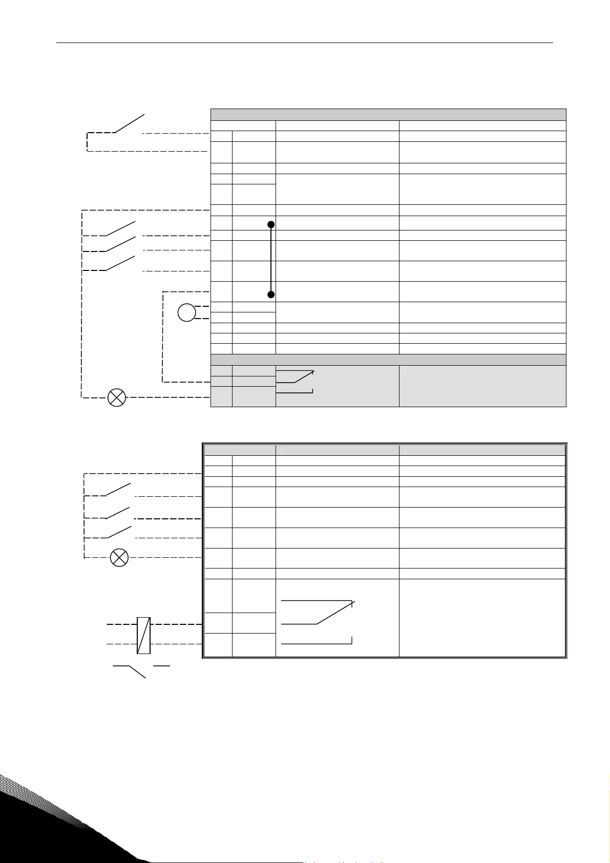
2. CONTROL I/O
NXL internal I/O board
Terminal Signal Description
1 +10V
AI1+
DIN4
3 AI1- I/O Ground Ground for reference and controls
4 AI2+
5 AI2-
/GND
6 +24V Control voltage output Voltage for switches, etc. max 0.1 A
7 GND
8 DIN1 Start forward (programmable) Contact closed = start forward
9 DIN2 Start reverse (programmable) Contact closed = start reverse
10 DIN3 Fault Reset
11 GND I/O ground Ground for reference and controls
Reference output Voltage for potentiometer, etc.
ref
Analogue input, voltage range
0—10V DC.
Analogue input, voltage range
0—10V DC, or current range
0/4—20mA
I/O ground Ground for reference and controls
(programmable)
Voltage input
Used as digital input DIN4
Used as digital input DIN5
Contact open = No Reset
Contact closed = Reset
220
VAC
mA
18 AO1+
19 AO1-
A RS 485 Serial bus Differential receiver/transmitter
B RS 485 Serial bus Differential receiver/transmitter
30 +24V 24V aux. input voltage Control power supply backup
Output frequency
Analogue output
Programmable. Can be used as DO2
Range 0—20 mA/R
, max. 500Ω
L
21 RO1
22 RO1
23 RO1
Relay output 1
RUN
Programmable
Table 2-1. Lift application default I/O configuration.
I/O terminals on option board OPT-AA
Terminal Signal in application Description
X3
1 +24V Control voltage output Voltage for switches etc, max. 150 mA
2 GND I/O ground Ground for reference and controls
3 DIN1 DIE1 Speed reference selection
4 DIN2 DIE2 Speed reference selection
5 DIN3 DIE3 Speed reference selection
6 DO1 Exp. D01, Ready Open collector output, 50mA/48V,
X5
24 RO1
25 RO1
26 RO1
Exp R01, Mechanical brake Relay output 1 (NO),
(programmable)
(programmable)
(programmable)
programmable
function programmable
Switching capacity:
24VDC/8A
250VAC/8A
125VDC/0,4A
Table 2-2. I/O terminals of option board NXOPTAA
Note! The +24 V control voltage terminal can also be used to power the control module (but not the
power module).
Tel. +358 (0)201 2121 • Fax +358 (0)201 212 205
Page 5

Lift Application – Parameter lists vacon • 5
3. LIFT APPLICATION – PARAMETER LISTS
On the next pages you will find the lists of parameters within the respective parameter groups. The
parameter descriptions are given on pages 13 to 40.
Column explanations:
Code = Location indication on the keypad; Shows the operator the present param.
Number
Parameter = Name of parameter
Min = Minimum value of parameter
Max = Maximum value of parameter
Unit = Unit of parameter value; Given if available
Default = Value preset by factory
Cust = Customer’s own setting
ID = ID number of the parameter (used with PC tools)
= On the parameter code: parameter value can only be changed after the FC has
been stopped.
3.1 Monitoring values (Control keypad: menu M1)
The monitoring values are the actual values of parameters and signals as well as statuses and
measurements. Monitoring values cannot be edited.
See Vacon NXL User’s Manual, Chapter 7.4.1 for more information.
Code Parameter Unit ID Description
V1.1 Output frequency Hz 1 Output frequency to motor
V1.2 Frequency reference Hz 25 Frequency reference to motor control
V1.3 Motor speed rpm 2 Motor speed in rpm
V1.4 Motor current A 3 Measured motor current
V1.5 Motor torque % 4 In % of the nominal motor torque
V1.6 Motor power % 5 Motor shaft power
V1.7 Motor voltage V 6 Calculated motor voltage
V1.8 DC link voltage V 7 Measured DC-link voltage
V1.9 Unit temperature
V1.10 Analogue input 1
V1.11 Analogue input 2 14 AI2, used as digital input DIN5
V1.12 Analogue I
V1.13 DIN1, DIN2, DIN3 15 Digital input statuses
V1.14 DIE1, DIE2, DIE3 33 I/O Expander board: Digital input statuses
V1.15 RO1, ROE1, DOE1 1720 Relay and digital output statuses
V1.16 Lift Speed m/s 1719 Lift speed in m/s
mA 26 AO1
out
°C
8 Heatsink temperature
13 AI1, used as digital input DIN4
Table 3-1. Monitoring values
24-hour support +358 (0)40 837 1150 • Email: vacon@vacon.com
Page 6
6 • vacon Lift Application – Parameter lists
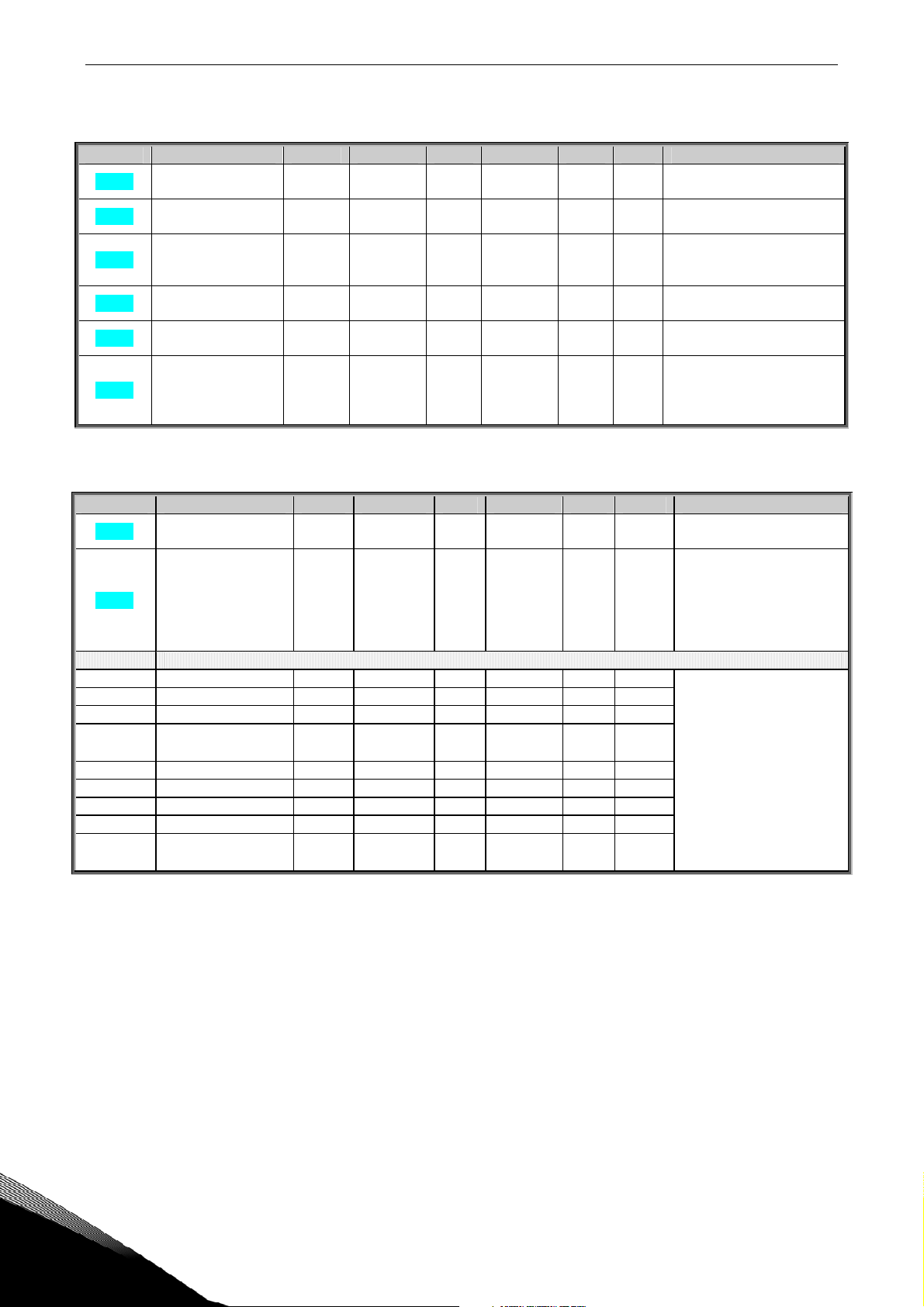
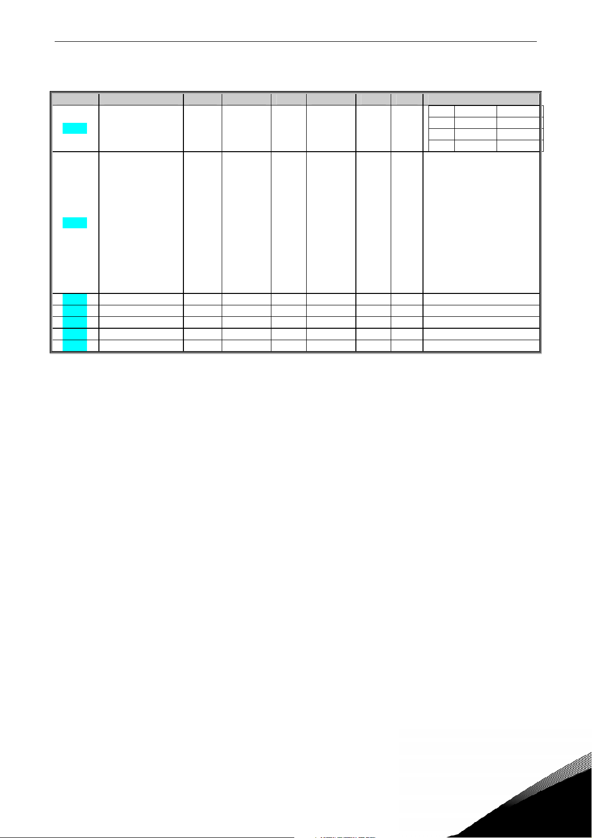
3.2 Motor Parameters (Control keypad: Menu P2 Æ P2.1)
Code Parameter Min Max Unit Default Cust ID Note
P2.1.1
P2.1.2
P2.1.3
P2.1.4
P2.1.5
P2.1.6 Current limit 0,1 x IL 1,5 x IL A IL
Nominal voltage of
the motor
Nominal frequency
of the motor
Nominal speed of the
motor
Nominal current of
the motor
Motor cosϕ
180 690 V
0,00 320,00 Hz 50,00
0 20 000 Rpm rpm
0,3 x IL 1,5 x IL A IL
0,30 1,00 0,85
NXL2:230V
NXL5:400V
110
Check the rating plate of
111
the motor
The default applies for a 4-
112
pole motor and a nominal
size frequency converter.
Check the rating plate of
113
the motor
Check the rating plate of
120
the motor
NOTE: Formulas apply
approx. up to MF3. For
107
greater sizes consult the
factory.
Table 1-2. Motor parameters P2.1
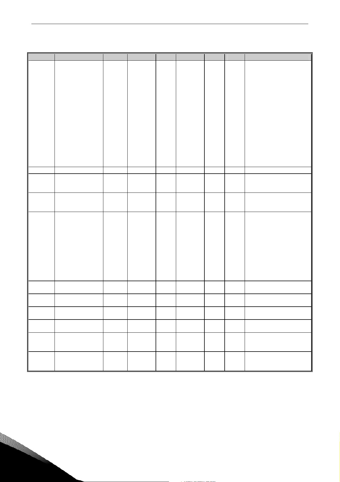
3.3 Speed control (Control keypad: Menu P2 Æ P2.2)
Code Parameter Min Max Unit Default Cust ID Note
P2.2.1
P2.2.2
P2.2.3.x Speed Reference [m/s]
P2.2.3.1 Levelling Speed 0,00 par2.2.1 m/s 0,10 1602
P2.2.3.2 Nominal Speed 0,00 par2.2.1 m/s 1,00 1603
P2.2.3.3 Limited Speed 0,00 par2.2.1 m/s 0,25 1604
P2.2.3.4 Inspection Speed 0,00
P2.2.3.5 Speed Reference 4 0,00 par2.2.1 m/s 0,10 1606
P2.2.3.6 Speed Reference 5 0,00 par2.2.1 m/s 1,00 1607
P2.2.3.7 Speed Reference 6 0,00 par2.2.1 m/s 0,25 1608
P2.2.3.8 Speed Reference 7 0,00 par2.2.1 m/s 0,50 1609
P2.2.3.9 Override speed 0,00
Nominal Linear
Speed
Speed Reference
Selection
0,20 5,00 m/s 1,00
0 4 0
1,5 x
par2.2.1
1,5 x
par2.2.1
m/s 0,50
m/s 0,10
1600 Nominal speed for lift
1601
1605
1610
0=Activity Reference
1=Activity Reference with
direction
2=Binary reference
3=Fieldbus
4=Keypad
Tel. +358 (0)201 2121 • Fax +358 (0)201 212 205
Page 7

Lift Application – Parameter lists vacon • 7
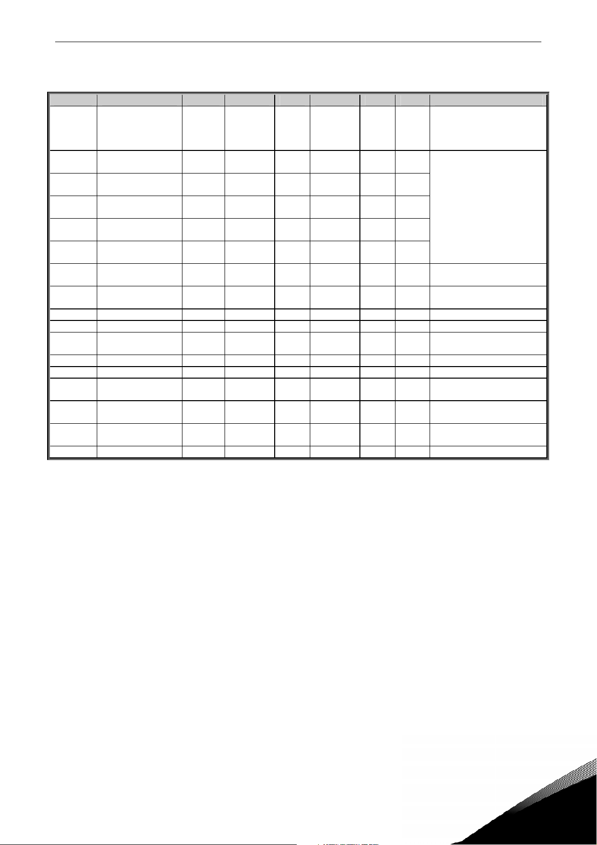
Code Parameter Min Max Unit Default Cust ID Note
P2.2.4.x SPEED CURVE 1
P2.2.4.1 Acceleration 1 0,20 2,00 m/s2 0,70 103
P2.2.4.2 Deceleration 1 0,20 2,00 m/s2 0,70 104
P2.2.4.3
P2.2.4.4
P2.2.4.5
P2.2.4.6
P2.2.5.x SPEED CURVE 2
P2.2.5.1
P2.2.5.2 Acceleration 2 0,20 2,00 m/s2 0,20 1711
P2.2.5.3 Deceleration 2 0,20 2,00 m/s2 0,20 1712
P2.2.5.4
P2.2.5.5
P2.2.5.6
P2.2.5.7
Acceleration increase
jerk 1
Acceleration
Decrease jerk 1
Deceleration increase
jerk 1
Deceleration
decrease jerk 1
Internal Ramp
Switch
Acceleration increase
jerk 2
Acceleration
decrease jerk 2
Deceleration increase
jerk2
Deceleration
decrease jerk 2
0,01 3,00 S 0,50
0,01 3,00 S 0,25
0,01 3,00 S 0,25
0,01 3,00 S 0,50
0 MaxFreq Hz 0
0,01 3,00 S 0,50
0,01 3,00 S 0,50
0,01 3,00 S 0,50
0,01 3,00 S 0,50
1611
1612
1613
1614
1710
1713
1714
1715
1716
Table 3-3. Speed control parameters P2.2
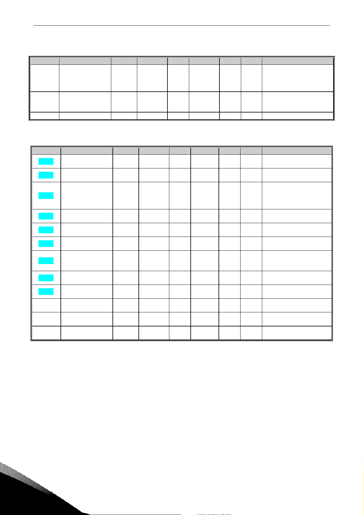
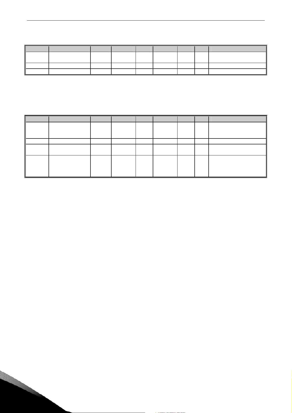
3.4 Mechanical Brake control parameters (Control keypad: Menu M2 Æ P2.3)
Code Parameter Min Max Unit Default Cust ID Note
G2.3.1.x
P2.3.1.1 Current limit FWD 0 par2.1.4 A 0 1700
P2.3.1.2 Current limit REV 0 par2.1.4 A 0 1701
P2.3.1.3 Torque limit FWD 0 100,0 % 30 1702
P2.3.1.4 Torque limit REV 0 100,0 % 30 1703
P2.3.1.5 Frequency limit FWD 0 par2.1.2 Hz 1,00 1704
P2.3.1.6 Frequency limit REV 0 par2.1.2 Hz 1,00 1705
P2.3.1.7 Brake Open Delay 0 10,00 s 0,15 1706
P2.3.1.8 MecBr React Time 0 10,0 s 0,05
P2.3.1.9 MaxFreqBrClosed 0 MaxFreq Hz 4,0
G2.3.2.x
P2.3.2.1 Freq. Limit close 0,01 par2.1.2 Hz 2,00
P2.3.2.2 Brake close delay 0 10,0 s 0,0 1708
OPENING BRAKE
CLOSING BRAKE
1622
1621
1707
Mechanical brake
physical reaction time
Maximum allowed
frequency reference
when brake is closed
Frequency limit for
closing brake when
stopping
Table 3-4. Mechanical brake control parameters G2.3.
G2.3.3.x
P2.3.3.1 DC brake current
P2.3.3.2 Start DC-brake time 0 600,00 S 1,00 1750 0=DC brake is off at start
P2.3.3.3 Stop DC-brake time 0 600,00 S 1,00 1717 0=DC brake is off at stop
P2.3.3.4
DC BRAKE
Stop DC-brake
frequency
MinCurr
ent
0,10 10,00 Hz 3,00
1,5 x IN A Varies
1740
515
Table 3-5. DC brake control parameters G2.3.3
24-hour support +358 (0)40 837 1150 • Email: vacon@vacon.com
Page 8
8 • vacon Lift Application – Parameter lists
3.5 Drive Control (Control keypad: Menu M2 Æ P2.4)
Code Parameter Min Max Unit Default Cust ID Note
P2.4.1 Brake chopper 0 3 1
0=Disabled
1=Used in Run state
504
2=Used in Run state
3=Ready
P2.4.2 Stop Function 0 2 2
506
0=Coasting
1=Ramping
2=Stop type by Freq. Limit
P2.4.3 Frequency limit 0 MaxFreq Hz 5,00 1623 Used only if par 4.2=2
Table 3-6. Drive control parameters P2.4
3.6 Motor control parameters (Control keypad: Menu P2 Æ P2.5)
Code Parameter Min Max Unit Default Cust ID Note
P2.5.1 Motor control mode 0 1 1
P2.5.2 U/f Optimization 0 1 0
P2.5.3 U/f ratio selection 0 3 0
0=Frequency control
600
1=Speed control
0=None
109
1=Automatic torque boost
0=Linear
1=Squared
108
2=Programmable
3=Linear with flux optim.
P2.5.4
P2.5.5
P2.5.6
P2.5.7
P2.5.8
P2.5.9 Switching frequency 1,0
P2.5.10
P2.5.11
Field weakening
point
Voltage at field
weakening point
U/f curve midpoint
frequency
U/f curve midpoint
voltage
Output voltage at
zero frequency
Overvoltage
controller
Undervoltage
controller
30,00 320,00 Hz 50,00
10,00 200,00 % 100,00
0,00
par.
P2.5.4
Hz 50,00
0,00 100,00 % 100,00
0,00 40,00 % 0,00
Max
SwFreq.
KHz 6,0
0 1 0
0 1 0
P2.5.12 Meas.RsVolt Drop 0 10000
602
603 n% x U
604
n% x U
605
Parameter max. value =
par. 2.5.5
606 n% x U
601 Depends on kW
1721
0=Not used
607
1=Used
0=Not used
608
1=Used
Measured Voltage drop at
stator resistance
nmot
nmot
nmot
Table 3-7. Motor control parameters P2.5
Tel. +358 (0)201 2121 • Fax +358 (0)201 212 205
Page 9
Lift Application – Parameter lists vacon • 9
3.7 Input Signals (Control keypad: Menu P2 Æ P2.6)
Code Parameter Min Max Unit Default Cust ID Note
P2.6.1 Start/stop Logic 0 2 0
P2.6.2
P2.6.3 DIN4 (AI1)Function 0 12 2 499 As parameter 2.6.2
P2.6.4 DIN5 (AI2)Function 0 12 0
P2.6.5 DIE1 Function 0 12 10 368 As parameter 2.6.2
P2.6.6 DIE2 Function 0 12 11 330 As parameter 2.6.2
P2.6.7 DIE3 Function 0 12 12 369 As parameter 2.6.2
DIN3
Function
0 12 4
300
301
1500
DIN1 DIN2
0 ForwP RevP
1 Start Rev
2 Forw Rew
0=Not used
1=Speed curve 2
2=Ext Fault close
3=Ext Fault open
4=Fault Reset
5=Run Enable
6=Emergency stop CC
7=Emergency stop OC
8=Override speed
9=Brake open Enable
10=Speed Reference 1
11=Speed Reference 2
12=Speed Reference 3
As parameter 2.6.2
Table 3-8. Input signals P2.6
24-hour support +358 (0)40 837 1150 • Email: vacon@vacon.com
Page 10
10 • vacon Lift Application – Parameter lists
3.8 Output signals (Control keypad: Menu P2 Æ P2.7)
Code Parameter Min Max Unit Default Cust ID Note
0=Not used
1=Ready
2=Run
3=Fault
4=Fault inverted
5=FC overheat warning
6=Ext. fault or warning
P2.7.1
Relay output 1
function
0 16 2
313
7=Not Used
8=Warning
9=Reversed
10=Preset speed
11=At speed
12=Mot. regulator active
13=OP freq. limit superv.1
14=Control place: IO
15=Thermistor fault/ warn
16=Mechanical brake
P2.7.2 DO2 (AO1) function 0 16 3 490 As parameter 2.7.1
P2.7.3
Expander board
relay output 1
0 16 16
314 As parameter 2.7.1
function
312 As parameter 2.7.1
P2.7.4
Expander board
digital output 1
0 16 1
function
0=Not used
1=Output freq. (0—f
max
2=Freq. reference (0—f
)
)
max
3=Motor speed (0–Motor
nominal speed)
4=Output current (0—I
5=Motor torque (0—T
6=Motor power (0—P
7=Motor voltage (0--U
nMotor
nMotor
nMotor
nMotor
)
)
)
)
P2.7.5
Analogue output
function
0 9 1
307
8=DC-link volt (0—1000V)
9=Digital output 2
P2.7.6
P2.7.7
P2.7.8
P2.7.9
P2.7.10
P2.7.11
Analogue output
filter time
Analogue output
inversion
Analogue output
minimum
Analogue output
scale
Output frequency
limit 1 supervision
Output frequency
limit 1;
0,00 10,00 S 1,00
0 1 0
0 1 0
10 1000 % 100
0 2 0
0,00 Max Freq Hz 0,00
308 0=No filtering
309
310
311
315
316
0=Not inverted
1=Inverted
0=0 mA
1=4 mA
0=No limit
1=Low limit supervision
2=High limit supervision
Supervised value
Table 3- 9. Output signals, P2.7
Tel. +358 (0)201 2121 • Fax +358 (0)201 212 205
Page 11
Lift Application – Parameter lists vacon • 11
3.9 Protections (Control keypad: Menu P2 Æ P2.8)
Code Parameter Min Max Unit Default Cust ID Note
P2.8.1
Response to external
fault
0 3 0
0=No response
1=Warning
701
2=Fault,stop acc. to 2.4.2
3=Fault,stop by coasting
P2.8.2
P2.8.3
P2.8.4
P2.8.5
P2.8.6
P2.8.7
Response to
undervoltage fault
Output phase
supervision
Earth fault
protection
Thermal protection
of the motor
Motor ambient
temperature factor
Motor cooling factor
at zero speed
P2.8.8 Motor thermal time
constant
1 3 2
0 3 2
0 3 2
0 3 2
–100,0 100,0 % 0,0
0,0 150,0 % 40,0
1 200 Min 45
727
702
0=No response
1=Warning
703
2=Fault,stop acc. to 2.4.2
3=Fault,stop by coasting
704
705
706
707
P2.8.9 Motor duty cycle 0 100 % 100 708
P2.8.10 Stall protection 0 3 1 709 As par. 2.7.1
P2.8.11
Stall current limit 0 2x I
A
nmotor
I
nmotor
x1.3
710
P2.8.12 Stall time limit 1,00 120,00 S 15,00 711
P2.8.13 Stall frequency limit 1,0 P 2.1.2 Hz 25,0 712
P2.8.14
Response to
thermistor fault
P2.8.15 Response to
fieldbus fault
P2.8.16 Response to slot
fault
0 3 0
0 3 2
0 3 2
732 As par. 2.7.1
733 As par. 2.7.1
734 As par. 2.7.1
P2.8.17 Min. Current Limit 0 P 2.1.4 A 1760
Table 3-10. Protections, P2.8
24-hour support +358 (0)40 837 1150 • Email: vacon@vacon.com
Page 12
12 • vacon Lift Application – Parameter lists
3.10 Autorestart parameters (Control keypad: Menu P2 Æ P2.9)
Code Parameter Min Max Unit Default Cust ID Note
P2.9.1 Enable/Disable 0 1 0
P2.9.2 Wait time 0,10 10,00 s 0,50 717
P2.9.3 Trial time 0,00 60,00 s 30,00 718
731
0=Disabled
1=Enabled
Table 3-11. Autorestart parameters, P2.9
3.11 Keypad control (Control keypad: Menu K3)
The parameters for the selection of control place and direction on the keypad are listed below. See
the Keypad control menu in the Vacon NXL User’s Manual.
Code Parameter Min Max Unit Default Cust ID Note
P3.1 Control place 1 3 1
R3.2 Freq reference 0 MaxFreq Hz 0
P3.3 Direction (on keypad) 0 1 0
R3.4 Stop button 0 1 1
1 = I/O terminal
125
2 = Keypad
3 = Fieldbus
0 = Forward
123
1 = Reverse
0=Limited function of Stop
114
button
1=Stop button always
enabled
Table 3 12. Keypad control parameters, K3
3.12 System menu (Control keypad: Menu S6)
For parameters and functions related to the general use of the frequency converter, such as
customised parameter sets or information about the hardware and software, see Chapter 7.4.6 in
the Vacon NXL User’s Manual.
3.13 Expander boards (Control keypad: Menu E7)
The E7 menu shows the expander boards attached to the control board and board-related
information. For more information, see Chapter 7.4.7 in the Vacon NXL User’s Manual.
Tel. +358 (0)201 2121 • Fax +358 (0)201 212 205
Page 13

description of parameters vacon • 13
4. DESCRIPTION OF PARAMETERS
2.1 MOTOR PARAMETERS
2.1.1 Nominal voltage of the motor
Find this value Un on the rating plate of the motor. This parameter sets the voltage at
the field weakening point (parameter 2.5.5) to 100% x U
nmotor
.
2.1.2 Nominal frequency of the motor
Find this value fn on the rating plate of the motor. This parameter sets the field
weakening point (parameter 2.5.4) to the same value.
2.1.3 Nominal speed of the motor
Find this value nn on the rating plate of the motor.
2.1.4 Nominal current of the motor
Find this value In on the rating plate of the motor.
2.1.5 Motor cos phi
Find this value “cos phi” on the rating plate of the motor.
2.1.6 Current limit
This parameter determines the maximum motor current from the frequency converter.
To avoid motor overload, set this parameter according to the rated current of the
motor. The current limit is equal to the rated converter current (I
) by default.
L
24-hour support +358 (0)40 837 1150 • Email: vacon@vacon.com
Page 14

14 • vacon description of parameters
2.2 SPEED CONTROL
2.2.1 Nominal Linear Speed
Nominal linear speed corresponds to the lift speed at nominal frequency of the motor
(parameter 2.1.2)
Speed parameters in group 2.2.3 are entered in linear magnitudes.
2.2.2 Speed reference selection
Defines which frequency reference source is selected when controlled from the I/O
control place. Default value is 0.
0 = Activity coding
1 = Activity coding with direction
2 = Binary coding
4 = Fieldbus
5 = Keypad
Speed reference can be determined in three different ways with the external digital
inputs on option board.
The first column contains the state of the digital inputs (marked as DIE1, DIE2 and
DIE2).
The second column contains the parameter and the next column the corresponding
speed reference. The priority column defines which speed is activated if more than one
digital input is activated. If Speed reference is different when running to different
direction the direction is defined in direction column.
0 = Activity coding
Four different constant speeds can be selected.
DIE
[1,2,3]
[0;0;0] 2.2.3.1 (levelling speed) 0 low irrelevant
[1;0;0]
[0;1;0]
[0;0;1]
Parameters SpeedRef Priority Direction
2.2.3.2 (nominal speed) 1 medium irrelevant
2.2.3.3 (limited speed) 2 high irrelevant
2.2.3.4 (inspection speed) 3 highest irrelevant
Table 4-1. Activity reference.
Tel. +358 (0)201 2121 • Fax +358 (0)201 212 205
Page 15

description of parameters vacon • 15
1 = Activity coding with direction
The constant speeds are selected according to the state of digital inputs and motor
direction. Four different speeds per direction are available.
DIE
[1,2,3]
[0;0;0] 2.2.3.1 (levelling speed) 0 low forward
[1;0;0]
[0;1;0]
[0;0;1]
[0;0;0] 2.2.3.5 (preset speed 4) 0 low reverse
[1;0;0]
[0;1;0]
[0;0;1]
Parameters SpeedRef Priority Direction
2.2.3.2 (nominal speed) 1 medium forward
2.2.3.3 (limited speed) 2 high forward
2.2.3.4 (inspection speed) 3 highest forward
2.2.3.6 (preset speed 5) 1 medium reverse
2.2.3.7 (preset speed 6) 2 high reverse
2.2.3.8 (preset speed 7) 3 highest reverse
Table 4--2. Activity reference with direction.
2 = Binary coding
Eight different constant speeds are selected according to binary word formed through
digital inputs.
DIE
[1,2,3]
[0;0;0] 2.2.3.1 (levelling speed) - irrelevant
[1;0;0]
[0;1;0]
[1;1;0]
[0;0;1]
[1;0;1]
[0;1;1]
[1;1;1]
Parameters SpeedRef Priority Direction
2.2.3.2 (nominal speed) - irrelevant
2.2.3.3 (limited speed) - irrelevant
2.2.3.4 (inspection speed) - irrelevant
2.2.3.5 (preset speed 4) - irrelevant
2.2.3.6 (preset speed 5) - irrelevant
2.2.3.7 (preset speed 6) - irrelevant
2.2.3.8 (preset speed 7) - irrelevant
Table 4-3. Binary reference.
Speed reference [m/s] parameters (M2 -> G2.2.3)
Parameters in group 2.2.3 define the speed reference in linear magnitudes [m/s].
2.2.3.1 Levelling Speed
2.2.3.2 Nominal Speed
2.2.3.3 Limited Speed
2.2.3.4 Inspection Speed
2.2.3.5 Speed reference 4
2.2.3.6 Speed reference 5
2.2.3.7 Speed reference 6
2.2.3.8 Speed reference 7
2.2.3.9 Override Speed
24-hour support +358 (0)40 837 1150 • Email: vacon@vacon.com
Page 16

16 • vacon description of parameters
Speed Curve 1 parameters (M2 -> G2.2.4)
Speed curve 1 is used as the default values for acceleration and deceleration and jerks.
2.2.4.1 Acceleration time 1
2.2.4.2 Deceleration time 1
Acceleration and deceleration of the lift car are presented in [m/s2]. Acceleration and
deceleration curves are affected by the jerk time settings, too.
2.2.4.3 Acc inc jerk 1
Acceleration increase jerk1.
Jerk times are presented in [ms].
Speed [m/s]
acceleration
2
[m/s
]
P2.2.4.1
Figure 1. Jerks related to speed and acceleration
2.2.4.4 Acc dec jerk 1
Acceleration decrease jerk 1.
2.2.4.5 Dec inc jerk 1
Deceleration increase jerk 1.
2.2.4.6 Dec dec jerk 1
Deceleration decrease jerk 1.
P2.2.4.3
t [s]
P2.2.4.4
t [s]
Tel. +358 (0)201 2121 • Fax +358 (0)201 212 205
Page 17

description of parameters vacon • 17
Speed Curve 1 parameters (M2 -> G2.2.5)
Parameters in group Speed curve 2 are used when internal ramp switch function is
activated (see parameter P2.2.5.1). Then the Speed curve 1 parameters will be
replaced by Speed curve 2 parameters.
2.2.5.1 Internal Ramp switching frequency
0 = Not used
The ramp set 2 (Speed Curve2 parameters) can be activated internally. The update is
done when the speed is decelerated below the internal ramp switch frequency and the
reference frequency is reached.
Ramp set 1 (Speed Curve1 parameters) is changed back when the Run request of the
frequency converter is inactivated.
2.2.5.2 Acceleration time 2
2.2.5.3 Deceleration time 2
Acceleration and deceleration of the lift car are presented in [m/s2]. Acceleration and
deceleration curves are affected by the jerk time settings, too.
2.2.5.4 Acc inc jerk 2
Acceleration increase jerk 2. See Figure 1. Jerks related to speed and acceleration.
2.2.5.5 Acc dec jerk 2
Acceleration decrease jerk 2.
2.2.5.6 Dec inc jerk 2
Deceleration increase jerk 2.
2.2.5.7 Dec dec jerk 2
Deceleration decrease jerk 2.
24-hour support +358 (0)40 837 1150 • Email: vacon@vacon.com
Page 18

18 • vacon description of parameters
2.3 MECHANICAL BRAKE CONTROL
The mechanical brake control parameters affect the mechanical brake control, the
smooth start and stop function and the safety functions.
The mechanical brake can be set to release on current, on torque or on frequency.
These parameters can be set individually for forward and reverse direction
DIN3 or DIN4 can be programmed for brake open Enable.
The closing is performed by frequency and by Run request signal. In case of fault the
brake closes immediately without delay.
f/Hz
Max Freq
Brake closed
P2.3.1.9
Cur/Freq lim
P2.3.1.1-6
Run Request
signal
DC- Brake
P2.3.3.1-4
Br Open Del
P2.3.1.7
BR Mec Delay
P2.3.1.8
Brake Cl Del
P2.3.2.2
Brake Open
R02
P2.2.3.1
Levelling Speed
*)
P2.3.3.4
StopDC Freq
P2.3.2.1
FreqCloseLim
Figure 2. Mechanical brake control logic.
*) Start signal to Brake open delay when current, freq. and torque exceed limits defined by
parameters.
Tel. +358 (0)201 2121 • Fax +358 (0)201 212 205
Page 19

description of parameters vacon • 19
Mechanical Brake Control Logic
BRAKE OPENING LOGIC
MOTOR CURRENT
P2.3.1.1/2.3.1.2
.CURRENT LIMIT
MOTOR TORQUE
P2.3.1.3/2.3.1.4
TORQUE LIMIT
MOTOR FREQ
P2.3.1.5/2.3.1.6
FREQ LIMIT
DIN3/DIN4
BRAKE CLOSING LOGIC
V1.1
OUTPUT FREQ
P2.3.2.1
FREQ CLOSE LIMIT
EXT. BR INPUT SIGNAL
MOTOR RUNNING
P2.3.1.7
P2.3.2.2
BRAKE OPEN DELAY
A N D
BRAKE CLOSE DELAY
A N D
To n
To n
FAULT ACTIVE
O R
S E T
R E S E T
P2.7.1
or
P2.7.2
or
P2.7.3
MEC. BRAKE
CONTROL SIGNAL
RUN REQUEST
MOTOR RUNNING
Figure 3. Mechanical brake control logic.
Mechanical brake control signal can be selected to any digital or relay output to control the
external mechanical brake.
In the upper section of Figure 3 you can find the mechanical brake opening logic. Five signals and
the delay are required for the mechanical brake to open. If current, torque or frequency signal is
not needed for brake opening, then these parameters can be set to zero. The external brake input
signal is programmable for digital input DIN3 or DIN4.
In the lower section of Figure 3 you can find the mechanical brake closing logic. The brake close
circuit has higher priority than the open circuit. So if closing signal is active the mechanical brake
will be closed.
The brake will be closed immediately in case of fault or when the motor is stopped.
24-hour support +358 (0)40 837 1150 • Email: vacon@vacon.com
Page 20

20 • vacon description of parameters
In normal operation the brake will be closed when frequency falls below the Frequency close limit
(P2.3.2.1) AND when the Run Request signal is switched OFF. If the Frequency close limit signal is
not needed for the closing logic it can be set to zero. After the conditions are true there is a brake
close delay (P2.3.2.2) after which the brake will be closed.
Opening Brake Parameters (M2 -> G2.3.1)
Please note that there are limitations parameters for both Forward (FWD) and Reverse (REV)
direction.
Different values for FWD and REV can be set when application requires.
For example when counter weight is not used (e.g. Mechanical Brake Control application)
2.3.1.1 Current Limit FWD
Parameter defines the actual current limit that has to be exceeded for a brake release.
If set to zero this condition is excluded. The value is updated always when the nominal
current of the motor (parameter 2.1.4) is set (see Figure 3).
2.3.1.2 Current Limit REV
Parameter defines the actual current limit that has to be exceeded for a brake release.
If set to zero this condition is excluded. The value is updated always when the nominal
current of the motor (parameter 2.1.4) is set (see Figure 3).
2.3.1.3 Torque limit FWD
Parameter defines the actual torque limit that has to be exceeded for a brake release.
If set to zero this condition is excluded.
100 % corresponds to the calculated nominal torque of the motor (see Figure 3).
2.3.1.4 Torque limit REV
Parameter defines the actual torque limit that has to be exceeded for a brake release.
If set to zero this condition is excluded.
100 % corresponds to the calculated nominal torque of the motor (see Figure 3).
2.3.1.5 Frequency limit FWD
Parameter defines the actual frequency limit that has to be exceeded for brake
release. If set to zero this condition is excluded (see Figure 3).
2.3.1.6 Frequency limit REV
Parameter defines the actual frequency limit that has to be exceeded for brake
release. If set to zero this condition is excluded (see Figure 3).
2.3.1.7 Brake open delay
Delay which starts when the opening conditions (see parameters 2.3.1.1-2.3.1.6) are
TRUE (see Figure 3).
Tel. +358 (0)201 2121 • Fax +358 (0)201 212 205
Page 21

description of parameters vacon • 21
2.3.1.8 Mechanical brake reaction time
Mechanical brake reaction time will hold the speed reference for the defined time by
this parameter. This hold time should be set according to the mechanical brake
reaction time (see figure 2)
2.3.1.9 Maximum frequency brake closed
Output frequency does not exceed this value when mechanical brake is closed. When
modifying this parameter make sure that the brake release by frequency (see
parameter 2.3.1.5/2.3.1.6) is possible with new value.
Closing Brake Parameters (M2 -> G2.3.2)
2.3.2.1 Frequency limit closing
The output frequency limit for the brake closing. The run request signal needs to be
disabled to allow the signal to affect.
2.3.2.2 Closing delay
The brake closing is delayed with defined time. If set to zero there is no delay between
the brake closing condition and the actual brake closing.
24-hour support +358 (0)40 837 1150 • Email: vacon@vacon.com
Page 22

22 • vacon description of parameters
DC Brake Parameters (M2 -> G2.3.3)
2.3.3.1 DC-brake current
Defines the current injected into the motor during DC-braking.
2.3.3.2 DC-braking time at start
DC-brake is activated when the start command is given. This parameter defines the
time before the brake is released.
2.3.3.3 DC-braking time at stop
Determines if braking is ON or OFF and the braking time of the DC-brake when the
motor is stopping. The function of the DC-brake depends on the stop function,
parameter 2.4.2.
0 DC-brake is not used
>0 DC-brake is in use and its function depends on the Stop function,
(par. 2.4.2). The DC-braking time is determined with this parameter
Par. 2.4.2 = 0; Stop function = Coasting:
After the stop command, the motor coasts to a stop without control of the frequency
converter.
With DC-injection, the motor can be electrically stopped in the shortest possible time,
without using an optional external-braking resistor.
The braking time is scaled according to the frequency when the DC-braking starts. If
the frequency is ≥ the nominal frequency of the motor, the set value of parameter
2.3.3.3 determines the braking time. When the frequency is ≤10% of the nominal, the
braking time is 10% of the set value of parameter 2.3.3.3.
f
o u t
f
n
R U N
S T O P
O u t p u t
f r e q u e n cy
M
s p e e d
D
bra k i n g
C -
o t o r
O N
0,1 x f
t
f
n
n
RUN
STOP
f
out
Figure 4. DC-braking time when Stop mode = Coasting.
Output frequency
Motor speed
DC-braking ON
t = 1 x par. 2.3.3.3 t = 1 x par. 2.3.3.3
NX1 2 K 2 1
t
Tel. +358 (0)201 2121 • Fax +358 (0)201 212 205
Page 23

description of parameters vacon • 23
Par. 2.4.2 = 1; Stop function = Ramp
After the Stop command, the speed of
the motor is reduced according to the
set deceleration parameters, as fast
as possible, to the speed defined with
f
out
M o t o r
s p e e d
O u t p u t
f r e q u e n c y
parameter 2.3.3.4, where the DC-
braking starts.
The braking time is defined with
parameter 2.3.3.3. If high inertia
exists, it is recommended to use an
external braking resistor for faster
deceleration. See Figure 5.
P2.3.3.4
RUN
STOP
D C - b r a k i n g
t
t=1 x par. 2.3.3.3
NX12K23
Par. 2.4.2 = 2; Stop function = Stop by frequency. limit
Stop mode depends on the actual frequency of the motor. If frequency is above the
frequency limit (par. 2.4.3) then the stop mode is coasting (see Figure 4). If frequency is
even or below the frequency limit then the stop mode is ramp (see Figure 5).
2.3.3.4 DC-braking frequency at stop
The output frequency which the DC-braking is applied. See Figure 5
Figure 5. DC-braking time when Stop mode = Ramp
24-hour support +358 (0)40 837 1150 • Email: vacon@vacon.com
Page 24

24 • vacon description of parameters
2.4 DRIVE CONTROL
2.4.1 Brake chopper
0 = No brake chopper used
1 = Brake chopper in use when running
2 = Brake chopper in use when running
3 = Used drive is ready
When the frequency converter is decelerating the motor, the inertia of the motor and
the load are fed into an external brake resistor. This enables the frequency converter
to decelerate the load with a torque equal to that of acceleration (provided that the
correct brake resistor has been selected). See separate Brake resistor installation
manual.
2.4.2 Stop function
Coasting:
0 The motor coasts to a halt without any control from the frequency converter,
after the Stop command.
Ramp:
1 After the Stop command, the speed of the motor is decelerated according to
Frequency limit
2 Coasting Stop if the motor frequency is above the frequency limit (par. 2.4.3)
the set deceleration parameters.
If the regenerated energy is high it may be necessary to use an external
braking resistor for faster deceleration.
when stop request is given. Stop by ramp if the motor frequency is the same
or below this parameter when stop request is given.
2.4.3 Frequency limit
Defines the frequency limit for the stop function if selected as the frequency limit (par.
2.4.2=2).
If the motor frequency is above the frequency limit the motor costs to stop and if it is
below or the same as the frequency limit the stop function is ramp.
Tel. +358 (0)201 2121 • Fax +358 (0)201 212 205
Page 25

description of parameters vacon • 25
2.5 MOTOR CONTROL
2.5.1 Motor control mode
0 Frequency control: The I/O terminal and keypad references are frequency
references and the frequency converter controls the output
frequency (output frequency resolution = 0.01 Hz)
1 Speed control: The I/O terminal and keypad references are speed references
and the frequency converter controls the motor speed
(accuracy ± 0,5%).
2.5.2 U/f optimisation
Automatic
torque boost
NOTE!
2.5.3 U/f ratio selection
Linear: The voltage of the motor changes linearly with the frequency in the constant
0 flux area from 0 Hz to the field weakening point where the nominal voltage is
supplied to the motor. Linear U/f ratio should be used in constant torque
applications. This default setting should be used if there is no special
need for another setting.
Squared: The voltage of the motor changes following a squared curve form
1 with the frequency in the area from 0 Hz to the field weakening point where
the nominal voltage is also supplied to the motor. The motor runs under
magnetised below the field weakening point and produces less
torque and
electromechanical noise. Squared U/f ratio can be used in applications
where torque demand of the load is proportional to the square of the speed,
e.g in centrifugal fans and pumps.
The voltage to the motor changes automatically which makes the
motor produce sufficient torque to start and run at low
frequencies. The voltage increase depends on the motor type and
power. Automatic torque boost can be used in applications where
starting torque due to starting friction is high, e.g. in conveyors.
In high torque - low speed applications - it is likely that the motor
will overheat. If the motor has to run a prolonged time under these
conditions, special attention must be paid to cooling the motor. Use
external cooling for the motor if the temperature tends to rise too
high.
24-hour support +358 (0)40 837 1150 • Email: vacon@vacon.com
Page 26

26 • vacon description of parameters
U[V]
Un
par.2.5.5
Default: Nominal
voltage of the m otor
Linear
Field w eakening
point
Squared
Default: Nominal
frequency of the
motor
NX12K07
f[Hz]
Figure 6. Linear and squared change of motor voltage
Programmable U/f curve:
2 The U/f curve can be programmed with three different points.
Programmable U/f curve can be used if the other settings do not satisfy the
needs of the application.
U
[ V ]
D e f a u l t :
v
o l t a g e
N o m i n al
o f
t h e
motor
Field weakening point
P a r
U n
2 . 5 . 5
a r .
2 . 5 . 7
P
( D e f .
1 0 % )
8
2 . 5
1 . 3 % )
.
P a r .
( D e f .
P a r .
( D e f .
Figure 7. Programmable U/f curve.
Linear with flux optimisation:
3 The frequency converter starts to search for the minimum motor current in
order to save energy, lower the disturbance level and the noise. This function
can be used in applications with constant motor load, such as fans, pumps
etc.
2.5.4 Field weakening point
The field weakening point is the output frequency at which the output voltage reaches
the set (par. 2.5.5) maximum value.
2 . 5
5
H z)
Default: Nominal
frequency of the moto
.
6
Par. 2.5.4
r
f[H z ]
NX12 K 0 8
Tel. +358 (0)201 2121 • Fax +358 (0)201 212 205
Page 27

description of parameters vacon • 27
2.5.5 Voltage at field weakening point
Above the frequency at the field weakening point, the output voltage remains at the set
maximum value. Below the frequency at the field weakening point, the output voltage
depends on the setting of the U/f curve parameters. See parameters 2.5.2, 2.5.3, 2.5.6
and 2.5.7.
When the parameters 2.1.1 and 2.1.2 (nominal voltage and nominal frequency of the
motor) are set the parameters 2.5.4 and 2.5.5 are automatically given the
corresponding values. If you need different values for the field weakening point and the
maximum output voltage, change these parameters after setting the parameters 2.1.1
and 2.1.2.
2.5.6 U/f curve, middle point frequency
If the programmable U/f curve has been selected with the parameter 2.5.3 this
parameter defines the middle point frequency of the curve. See Figure 7.
2.5.7 U/f curve, middle point voltage
If the programmable U/f curve has been selected with the parameter 2.5.3 this
parameter defines the middle point voltage of the curve. See Figure 7.
2.5.8 Output voltage at zero frequency
If the programmable U/f curve has been selected with the parameter 2.5.3 this
parameter defines the zero frequency voltage of the curve. See Figure 7.
2.5.9 Switching frequency
Motor noise can be minimised using a high switching frequency. Increasing the
switching frequency reduces the capacity of the frequency converter unit.
The range of this parameter depends on the size of the frequency converter:
2.5.10 Overvoltage controller
2.5.11 Undervoltage controller
These parameters allow the under-/overvoltage controllers to be switched out of
operation. This may be useful, for example, if the mains supply voltage varies more
than –15% to +10% and the application will not tolerate this over-/undervoltage. In this
case, the regulator controls the output frequency taking the supply fluctuations into
account.
Note: Over-/undervoltage trips may occur when controllers are switched out of
operation.
0 Controller switched off
1 Controller switched on
2.5.12. Measured RS voltage drop
Measured Voltage drop at stator resistance between two phases of the motor with
nominal current of motor.
24-hour support +358 (0)40 837 1150 • Email: vacon@vacon.com
Page 28

28 • vacon description of parameters
2.6 INPUT SIGNALS
2.6.1 Start/Stop logic selection
0 DIN1: closed contact = start forward (rising edge pulse is required)
DIN2: closed contact = start reverse (rising edge pulse is required)
FWD
t
REV
DIN1
DIN2
1
2
Figure 8. Start forward/Start reverse
c If both DIN switches are ON at the same time the second input is ignored.
d The drive can be re-started when both DIN switches are in OFF position.
1 DIN1: closed contact = start open contact = stop
DIN2: closed contact = reverse open contact = forward
FWD
t
REV
DIN1
DIN2
Figure 9. Start, Stop, Reverse
2 DIN1: closed contact = start forward
DIN2: closed contact = start reverse
Same as selection 0 except rising edge pulse is not required.
Fault is not activated if both DIN switches are on.
Tel. +358 (0)201 2121 • Fax +358 (0)201 212 205
Page 29

description of parameters vacon • 29
2.6.2 DIN3 function
This parameter has 8 selections. If digital input DIN3 need not be used, set the
parameter value to 0.
1 Speed curve2
2 Ext Fault close
3 Ext Fault open
4 Fault reset
5 Run enable
6 Emergency stop CC
7 Emergency stop OC
8 Override speed
9 Brake open enable
2.6.3 DIN4 (Analog input 1) function
The analog input 1 is used as digital input DIN4.
Selections are the same as for Parameter 2.6.2
2.6.4 DIN5 (Analog input 2) function
The analog input 2 is used as digital input DIN5.
Selections are the same as for Parameter 2.6.2
2.6.5 Expander board DIE1 function
Function selection for Expander board digital input DIE1.
Selections are the same as for Parameter 2.6.2
2.6.6 Expander board DIE2 function
Function selection for Expander board digital input DIE2.
Selections are the same as for Parameter 2.6.2
2.6.7 Expander board DIE3 function
Function selection for Expander board digital input DIE3.
Selections are the same as for Parameter 2.6.2
24-hour support +358 (0)40 837 1150 • Email: vacon@vacon.com
Page 30

30 • vacon description of parameters
2.7 OUTPUT SIGNALS
2.7.1 Relay output 1 function
2.7.2 Digital output 2 (Analogue output 1) function
2.7.3 Expander board relay output 1 function
2.7.4 Expander board digital output 1 function
Setting value Signal content
0 = Not used Out of operation
1 = Ready The frequency converter is ready to operate
2 = Run The frequency converter operates (motor is running)
3 = Fault A fault trip has occurred
4 = Fault inverted A fault trip not occurred
5 = Frequency converter overheat
warning
6 = External fault or warning Fault or warning depending on par. 2.8.1
Relay output RO1 and expander board
programmable relays (RO1, D01) are activated when:
The heat-sink temperature exceeds +70°C
7 = Not Used Not Used
8 = Warning Always if a warning exists
9 = Reversed The reverse command has been selected
10 = Preset speed A preset speed has been selected
11 = At speed The output frequency has reached the set reference
12 = Motor regulator activated Overvoltage or overcurrent regulator was activated
13 = Output frequency limit 1
supervision
14 = Control from I/O terminals
15 = Thermistor fault or warning
16 = Mechanical brake
Table 4-4. Output signals via RO1, DO2 and expander board RO1, and DO1.
2.7.5 Analogue output function
This parameter selects the desired function for the analogue output signal.
See the table on page 10 for the parameter values. Maximum analogue output is
activated when output selected by P2.7.2 is true.
Not used in this application
Selected control place (Menu K3; par. 3.1) is “I/O
terminal”
The thermistor input of option board indicates
overtemperature. Fault or warning depending on
parameter 2.8.14
External brake ON/OFF control
(see parameter Group G2.3)
Tel. +358 (0)201 2121 • Fax +358 (0)201 212 205
Page 31

description of parameters vacon • 31
A
A
A
A
A
2.7.6 Analogue output filter time
Defines the filtering time of the analogue
output signal.
If you set value 0 for this parameter, no
filtering takes place.
2.7.7 Analogue output invert
Inverts the analogue output signal:
Maximum output signal = 0 %
Minimum output signal = Maximum set value (parameter 2.7.9)
0 Not inverted
1 Inverted
See parameter 2.7.9.
%
Unfiltered s i g n a l
F i l t e r e d s i g n a l
Par. 2.7.
5
Figure 10. Analogue output filtering
20 m
12 m
10 m
4 m
P a r a m . 2 . 7 . 8
=
2 0 0 %
0 m
0
0 . 5
t [s]
NX12K16
Param. 2.7.8
= 50%
Param. 2.7.8
= 100%
1.0
NX12K17
Figure 11. Analogue output invert
2.7.8 Analogue output minimum
Sets the signal minimum to either 0 mA or 4 mA (living zero). Note the difference in the
analogue output scaling in parameter 2.7.9.
24-hour support +358 (0)40 837 1150 • Email: vacon@vacon.com
Page 32

32 • vacon description of parameters
2.7.9 Analogue output scale
Scaling factor for the analogue output.
Signal Max. value of the signal
Output frequency 100% x f
max
Motor speed 100% x Motor nom. speed
Output current 100% x I
Motor torque 100% x T
Motor power 100% x P
Motor voltage 100% x U
nMotor
nMotor
nMotor
nmotor
DC-link voltage 1000 V
Table 1- 1. Analogue output scaling
Analogue
output
current
20 mA
12 mA
10 mA
Par. 2.7.7 = 1
Par. 2.7.7 = 0
4 mA
0 mA
a r . 2 . 7 . 8 =
P
2 0 0 %
0
0 . 5
P a r . 2 .7.8=
0 0 %
1
Par.2.7.8=
50%
Max. value of signal
selected by param. 2.7.4
1 .0
n x l k 4 9.fh8
Figure 12. Analogue output scaling
2.7.10 Output frequency limit 1 supervision function
0 No supervision
1 Low limit supervision
2 High limit supervision
If the output frequency goes under/over the set limit (par. 2.7.10) this function
generates a warning message via the relay outputs depending on the settings of
parameters 2.7.1 – 2.7.3
2.7.11 Output frequency limit 1 supervised value
Selects the frequency value supervised by parameter 2.7.9
P a r 2 . 7 . 1 0
E x a m p l e :
f[ H z ]
21 R O 1
22 R O 1
23 R O 1
Par 2.7.9 = 2
21 RO1
22 RO1
23 RO1
t
21 RO1
22 RO1
23 RO1
NX12K19
Figure 13. Output frequency supervision
Tel. +358 (0)201 2121 • Fax +358 (0)201 212 205
Page 33

description of parameters vacon • 33
2.8 PROTECTIONS
I/O Faults parameters (M2 -> G2.8.1)
2.8.1 Response to external fault
0 = No response
1 = Warning
2 = Fault, stop mode after fault according to parameter 2.4.2.
3 = Fault, stop mode after fault always by coasting
A warning or a fault action and message is generated from the external fault signal
in the programmable digital inputs. The information can also be programmed into relay
outputs.
2.8.2 Response to undervoltage fault
1 = Warning
2 = Fault, stop mode after fault according to parameter 2.4.2.
3 = Fault, stop mode after fault always by coasting
For the undervoltage limits see Vacon NXL User’s Manual. Table 4-3.
Note: This protection can not be inactivated.
2.8.3 Output phase supervision
0 = No response
1 = Warning
2 = Fault, stop mode after fault according to parameter 2.4.2.
3 = Fault, stop mode after fault always by coasting
Output phase supervision of the motor ensures that the motor phases have an
approximately equal current.
2.8.4 Earth fault protection
0 = No response
1 = Warning
2 = Fault, stop mode after fault according to parameter 2.4.2.
3 = Fault, stop mode after fault always by coasting
Earth fault protection ensures that the sum of the motor phase currents is zero. The
overcurrent protection is always working and protects the frequency converter from
earth faults with high currents.
24-hour support +358 (0)40 837 1150 • Email: vacon@vacon.com
Page 34

34 • vacon description of parameters
Motor Faults parameters
Parameters 2.8.5—2.8.8, Motor thermal protection:
General
The motor thermal protection is to protect the motor from overheating. The Vacon drive is capable
of supplying higher than nominal current to the motor. If the load requires this high current there
is a risk that the motor will be thermally overloaded. This is the case especially at low frequencies.
At low frequencies the cooling effect of the motor is reduced as well as its capacity. If the motor is
equipped with an external fan the load reduction at low speeds is small.
The motor thermal protection is based on a calculated model and it uses the output current of the
drive to determine the load on the motor.
The motor thermal protection can be adjusted with parameters. The thermal current I
the load current above which the motor is overloaded. This current limit is a function of the output
frequency.
!
CAUTION!
The calculated model does not protect the motor if the airflow to the
motor is reduced by blocked air intake grill.
specifies
T
2.8.5 Motor thermal protection
0 = No response
1 = Warning
2 = Fault, stop mode after fault according to parameter 2.4.2.
3 = Fault, stop mode after fault always by coasting
If tripping is selected the drive will stop and activate the fault stage.
Deactivating the protection, i.e. setting parameter to 0, will reset the thermal stage of
the motor to 0%.
2.8.6 Motor thermal protection: Motor ambient temperature factor
When the motor ambient temperature must be taken into consideration, it is
recommended to set a value for this parameter. The value of the factor can be set
between –100.0% and 100.0% where –100.0% corresponds to 0
maximum running ambient temperature of the motor. Setting this parameter value to
0% assumes that the ambient temperature is the same as the temperature of the
heatsink at power-on.
Tel. +358 (0)201 2121 • Fax +358 (0)201 212 205
°C and 100.0% to the
Page 35

description of parameters vacon • 35
2.8.7 Motor thermal protection: Cooling factor at zero speed
The cooling power can be set between
0—150.0% x cooling power at nominal
frequency. See Figure 14.
100%
par.
2.8.7=40%
Figure 14. Motor cooling power
2.8.8 Motor thermal protection: Time constant
This time can be set between 1 and 200 minutes.
This is the thermal time constant of the motor. The bigger the motor, the bigger the
time constant. The time constant is the time within which the calculated thermal model
has reached 63% of its final value.
The motor thermal time is specific to the motor design and it varies between different
motor manufacturers.
If the motor's t6–time (t6 is the time in seconds the motor can safely operate at six
times the rated current) is known (given by the motor manufacturer) the time constant
parameter can be set basing on it. As a rule of thumb, the motor thermal time constant
in minutes equals to 2xt6. If the drive is in stop state the time constant is internally
increased to three times the set parameter value. The cooling in the stop state is based
on convection and the time constant is increased. See also Figure 10.
Note: If the nominal speed (par. 2.1.3) or the nominal current (par. 2.1.4) of the motor
are changed this parameter is automatically set to the default value (45).
0
f
N X 1 2 k 6 2
f
n
24-hour support +358 (0)40 837 1150 • Email: vacon@vacon.com
Page 36

36 • vacon description of parameters
Θ
j
w
2.8.9 Motor thermal protection: Motor duty cycle
Defines how much of the nominal motor load is applied.
The value can be set to 0%…100%.
M o t o r
t emp e r a t u r e
1 0 5 %
M
c u r r e n t
I / I
o t o r
T
T r i p
a r e a
arning
Fault/
par. 2.8.3.1
M
o t o r
Time constant T
t e m p erature
*)
Changes by motor size and
ad
ustedwith parameter 2.8.8.
=
(I/I
*)
2
)
T
-t/T
)
(1-e
x
Time
NX12k82
Figure 15. Motor temperature calculation
Parameters 2.8.10-2.8.13, Stall protection:
General
The motor stall protection protects the motor from short time overload situations such as one
caused by a stalled shaft. The reaction time of the stall protection can be set shorter than that of
motor thermal protection. The stall state is defined with two parameters, 2.8.11 (Stall current) and
2.8.13 (Stall frequency). If the current is higher than the set limit and output frequency is lower
than the set limit, the stall state is true. There is actually no real indication of the shaft rotation.
Stall protection is a type of overcurrent protection.
2.8.10 Stall protection
0 = No response
1 = Warning
2 = Fault, stop mode after fault according to parameter 2.4.2
3 = Fault, stop mode after fault always by coasting
Setting the parameter to 0 will deactivate the protection and reset the stall time
counter.
Tel. +358 (0)201 2121 • Fax +358 (0)201 212 205
Page 37

description of parameters vacon • 37
2.8.11 Stall current limit
The current can be set to 0.0…I
For a stall stage to occur, the current
must have exceeded this limit. See
Figure 1- 20. The software does not
allow entering a greater value than
I
*2. If the parameter 2.1.4 Nominal
nMotor
current of motor is changed, this
parameter is automatically restored to
the default value (I
2.8.12 Stall time limit
This time can be set between 1.0 and
120.0s.
This is the maximum time allowed for a
stall stage. The stall time is counted by
an internal up/down counter.
If the stall time counter value goes above
this limit the protection will cause a trip
(see parameter 2.8.10).
nMotor
*1.3).
nMotor
*2.
I
Stal l a r e a
Par. 2.8.11
a r .
P
2 . 8 . 1 3
Figure 16. Stall characteristics settings
Par. 2.8.
Stall time cou n t e r
Trip are a
11
T
r i p / w a r n i n g
p a r .
2 . 8 . 10
T i m e
f
NX12k63
2.8.13 Maximum stall frequency
The frequency can be set between 1-f
For a stall state to occur, the output frequency must have remained below this limit.
Figure17. Stall time count
(par. 2.1.2).
max
Stall
No stall
NX12k64
24-hour support +358 (0)40 837 1150 • Email: vacon@vacon.com
Page 38

38 • vacon description of parameters
Parameters 2.8.14-2.8.17, other protections:
2.8.14 Response to thermistor fault
0 = No response
1 = Warning
2 = Fault, stop mode after fault according to parameter 2.4.2.
3 = Fault, stop mode after fault always by coasting
2.8.15 Response to fieldbus fault
Set here the response mode for the fieldbus fault if a fieldbus board is used. For more
information, see the respective Fieldbus Board Manual.
See parameter 2.8.14.
2.8.16 Response to slot fault
Set here the response mode for a board slot fault due to missing or broken board.
See parameter 2.8.14.
2.8.17 Minimum current limit
If actual current of the motor is below the minimum current limit fault is activated. The
fault is activated only when the mechanical brake is open.
Tel. +358 (0)201 2121 • Fax +358 (0)201 212 205
Page 39

description of parameters vacon • 39
A
)
2.9 AUTO RESTART PARAMETERS
2.9.1 Automatic restart: Enable
Set this parameter to 1 to enable the automatic restart function.
Restart function works for following faults:
Undervoltage, Overvoltage, Overcurrent, IGBT overtemperature, Motor
overtemperature and External fault.
2.9.2 Automatic restart: Wait time
Defines the time before the frequency converter tries to automatically restart the
motor after the fault has disappeared.
2.9.3 Automatic restart: Trial time
The Automatic restart function restarts the frequency converter when the faults have
disappeared and the waiting time has elapsed.
Fault trigger
Motor stop signal
Motor start signal
Supervision
Fault active
RESET/
Fault reset
Wait time
Par.2.9.1
Restart 1 Restart 2
Wait time
Par. 2.9.1
Trial time
Par.2.9.2
utoreset function:(Trials = 2
Wait time
Par. 2.9.1
NX12k67
Figure 10. Example of Automatic restart with two restarts.
The time count starts from the first autorestart. If the number of faults occurring
during the trial time exceeds three, the fault state becomes active. Otherwise the fault
is cleared after the trial time has elapsed and the next fault starts the trial time count
again.
If a single fault remains during the trial time, a fault state is true.
24-hour support +358 (0)40 837 1150 • Email: vacon@vacon.com
Page 40

40 • vacon description of parameters
2.10 KEYPAD CONTROL PARAMETERS
3.1 Control place
The active control place can be changed with this parameter. For more information,
see Vacon NXL User's Manual, Chapter 7.4.3.
3.2 Keypad frequency reference
The frequency reference can be adjusted from the keypad with this parameter. For
more information, see Vacon NXL User's Manual, Chapter 7.4.3.2.
3.3 Keypad direction
0 Forward: The rotation of the motor is forward, when the keypad is the active
control place.
1 Reverse: The rotation of the motor is reversed, when the keypad is the active
control place.
For more information, see Vacon NXL User's Manual, Chapter 7.4.3.3.
3.4 Stop button activated
If you wish to make the Stop button a "hotspot" which always stops the drive regardless
of the selected control place, give this parameter the value 1 (default). See Vacon NXL
User's Manual, Chapter 7.4.3.
See also parameter 3.1.
Tel. +358 (0)201 2121 • Fax +358 (0)201 212 205
Page 41

description of parameters vacon • 41
3. CONTROL SIGNALS IN LIFT APPLICATION
DIN#
DIE1
DIE2
DIE3
DIN1
DIN2
DIN#
Override Speed selection
Speed Selection:
Inpu t 1
Inpu t 2
Inpu t 3
Speed Reference
parameters:
P2.2.3.x
Fieldbus
Fw
Bw
Programmable
Start/Stop Logic
Run Enable
wit h Run Enable
P2.2.3.9
Override Speed
P2.2.2 Speed
Reference
P3.1
Control Place
Internal
Frequency reference
Reference
Reset Button
Start/Stop
Buttons
Internal
Start / Stop
Internal
Reverse
KeyPad
Start/Stop from Fieldbus
P3.3 Keypad Direction
Direction from Fieldbus
Fault Reset (Programmable)
DIN#
DIN# is Programm able input. Function for input can b e selected.
NOTE! Same function can be programmed for several inputs.
This feature must be used ver y car ef ully .
Figure 19. Control signal logic in the Lift Application
Internal
Fault Reset
1
24-hour support +358 (0)40 837 1150 • Email: vacon@vacon.com
Page 42

42 • vacon fault tracing
3.1 FAULT TRACING
When a fault is detected by the frequency converter control electronics, the drive is stopped and
the symbol F together with the ordinal number of the fault and the fault code appear on the
display. The fault can be reset with the
Reset button
on the control keypad or via the I/O terminal.
The faults are stored in the Fault history menu (H5) which can be browsed. The different fault
codes you will find in the table below.
The fault codes, their causes and correcting actions are presented in the table below. The
shadowed faults are A faults only. The items written in white on black background present faults
for which you can program different responses in the application. See parameter group
Protections.
Fault
code
1 Overcurrent Frequency converter has detected too
2 Overvoltage The DC-link voltage has exceeded the
3 Earth fault Current measurement has detected that
5 Charging switch The charging switch is open, when the
8 System fault - component failure
9 Undervoltage DC-link voltage is under the voltage
11 Output phase
13 Frequency
14 Frequency
Fault Possible cause Correcting measures
) in the motor cable:
n
supervision
converter
undertemperature
converter
overtemperature
high a current (>4*I
− sudden heavy load increase
− short circuit in motor cables
− unsuitable motor
limits defined in.
− too short a deceleration time
− high overvoltage spikes in utility
the sum of motor phase current is not
zero.
− insulation failure in cables or motor
START command has been given.
− faulty operation
− component failure
- faulty operation
limits defined in.
− most probable cause: too low a
supply voltage
− frequency converter internal fault
Current measurement has detected that
there is no current in one motor phase.
Heatsink temperature is under –10°C
Heatsink temperature is over 90°C.
Overtemperature warning is issued when
the heatsink temperature exceeds 85°C.
Check loading.
Check motor size.
Check cables.
Make the deceleration time longer.
Check motor cables and motor.
Reset the fault and restart.
Should the fault re-occur, contact the
distributor near to you.
Reset the fault and restart.
Should the fault re-occur, contact the
distributor near to you.
In case of temporary supply voltage
break reset the fault and restart the
frequency converter. Check the supply
voltage. If it is adequate, an internal
failure has occurred.
Contact the distributor near to you.
Check motor cable and motor.
Check the correct amount and flow of
cooling air.
Check the heatsink for dust.
Check the ambient temperature.
Make sure that the switching frequency
is not too high in relation to ambient
temperature and motor load.
Tel. +358 (0)201 2121 • Fax +358 (0)201 212 205
Page 43

fault tracing vacon • 43
15 Motor stalled Motor stall protection has tripped. Check motor.
16 Motor
overtemperature
17 Motor underload Motor underload protection has tripped.
EEPROM
22
24 Counter fault Values displayed on counters are
25 Microprocessor
29 Thermistor fault The thermistor input of option board has
34 Internal bus
39 Device removed Option board removed.
40 Device unknown Unknown option board or drive. Contact the distributor near to you.
41 IGBT temperature IGBT Inverter Bridge overtemperature
44 Device change Option board changed.
45 Device added Option board added. Reset
51 External fault Digital input fault. Digital input has been
52 Keypad
53 Fieldbus fault The data connection between the
54 Slot fault Defective option board or slot Check board and slot.
58 Minimum
checksum fault
watchdog fault
communication
communication
fault
Current
Motor overheating has been detected by
frequency converter motor temperature
model. Motor is overloaded.
Parameter save fault
− faulty operation
− component failure
incorrect
− faulty operation
− component failure
detected increase of the motor
temperature
Ambient interference or defective
hardware
Drive removed.
protection has detected too high a motor
current.
Option board has default settings.
programmed as external fault input and
this input is active.
The connection between the control
keypad and the frequency converter is
broken.
fieldbus Master and the fieldbus board is
broken
Motor Current is less than set limit of
P2.8.17
Decrease the motor load.
If no motor overload exists, check the
temperature model parameters.
Contact the distributor near to you
Reset the faultand restart.
Should the fault re-occur, contact the
distributor near to you.
Check motor cooling and loading
Check thermistor connection
(If thermistor input of the option board is
not in use it has to be short circuited)
Should the fault re-occur, contact the
distributor near to you.
Reset
Check loading.
Check motor size.
Reset
Check the programming and the device
indicated by the external fault
information. Check also the cabling of
this device.
Check keypad connection and possible
keypad cable.
Check installation.
If installation is correct contact the
nearest Vacon distributor.
Contact the nearest Vacon distributor.
Check motor cables
24-hour support +358 (0)40 837 1150 • Email: vacon@vacon.com
Page 44

Vaasa
Vacon Oyj (Headquarters and Production)
Runsorintie 7, 65380 Vaasa
firstname.lastname@vacon.com
tel. +358 (0) 201 2121
fax: +358 (0) 201 212 205
Helsinki
Vacon Oyj
Äyritie 12, 01510 Vantaa
tel. +358 (0)201 212 600
fax: +358 (0)201 212 699
Tampere
Vacon Oyj
Alasniitynkatu 30, 33700 Tampere
tel. +358 (0)201 2121
fax: +358 (0)201 212 750
sales companies and representative offices:
Austria
Vacon AT Antriebssysteme GmbH
Aumühlweg 21
2544 Leobersdorf
vacon.austria@vacon.com
tel. +43 2256 651 66
fax: +43 2256 651 66 66
Belgium
Vacon Benelux NV/SA
Interleuvenlaan 62
3001 Heverlee (Leuven)
info@vacon.be
tel. +32 (0)16 394 825
fax: +32 (0)16 394 827
France
Vacon France s.a.s.
Batiment le Sextant
462 rue Benjamin Delessert
Zl de Moissy Cramayel
BP 83
77 554 Moissy Cramayel
www.vacon-france.fr
tel. +33 (0)1 64 13 54 11
fax: +33 (0)1 64 13 54 21
Germany
Vacon GmbH
Gladbecker Str. 425
45329 Essen
tel. +49 (0)201/80670-0
fax: +49 (0)201/80670-93
Great Britain
Vacon Drives (UK) Ltd.
18 Maizefield
Hinckley Fields Industrial Estate
Hinckley
LE10 1YF Leicestershire
vacon.uk@vacon.com
tel. +44 (0)1455 611 515
fax: +44 (0)1455 611 517
Italy
Vacon S.p.A.
Via F.lli Guerra, 35
42100 Reggio Emilia
info@vacon.it
tel. +39 0522 276811
fax: +39 0522 276890
The Netherlands
Vacon Benelux BV
Weide 40, 4206 CJ Gorinchem
vacon.benelux@vacon.com
tel. +31 (0)183 642 970
fax: +31 (0) 183 642 971
Norway
Vacon AS
Langgata 2
3080 Holmestrand
vacon@vacon.no
tel. +47 330 96120
fax: +47 330 96130
PR China
Vacon Plc
Beijing Representative Office
A205, Grand Pacific Garden Mansion
8A Guanhua Road
Beijing 100026
www.vacon.com.cn
vacon.china@vacon.com
tel. +86 10 6581 3734
fax: +86 10 6581 3754
Rotatek Finland Oy
Laserkatu 6, 53850 Lappeenranta
tel. +358 (0)5 6243 870
fax: +358 (0)5 6243 871
Vacon Traction Oy
Alasniitynkatu 30, 33700 Tampere
tel. +358 (0)201 2121
fax: +358 (0)201 212 710
Russia
ZAO Vacon Drives
Bolshaja Jakimanka 31
stroenie 18
109180 Moscow
www.ru.vacon.com
tel. +7 (095) 974 1541
fax: +7 (095) 974 1554
ZAO Vacon Drives
2ya Sovetskaya 7, office 210A
191036 St. Petersburg
www.ru.vacon.com
tel. +7 (812) 332 1114
fax: +7 (812) 279 9053
Singapore
Vacon Plc
Singapore Representative Office
102F Pasir Panjang Road
#02-06 Citilink Warehouse Complex
Singapore 118530
vacon.singapore@vacon.com
tel. +65 6278 8533
fax: +65 6278 1066
Spain
Vacon Drives Ibérica S.A.
Miquel Servet, 2. P.l. Bufalvent
08240 Manresa
www.vacon.es
info@vacon.es
tel. +34 93 877 45 06
fax: +34 93 877 00 09
Sweden
Vacon AB
Torget 1
172 67 Sundbyberg
tel. +46 (0)8 293 055
fax: +46 (0)8 290 755
Vacon distributor:
 Loading...