

Page 1
UL STANDARDS ON CABLING
To obey the UL (Underwriters Laboratories)
regulations, use a UL-approved Class 1
copper wire with a minimum heat
resista nce of +158 or +167 °F (+70 or +75°C).
You can use the drive on a circuit that gives
a maximum of 50 000 rms symmetrical
amperes, and a maximum of 500 V AC,
when the drive is protected by Class T and
J fuses.
CABLE AND FUSE SIZES,
NORTH AMERICA
The recommended fuse types are class
T (UL & CSA). The fuse voltage rating
should be selected according to the supply
network. The final selection should be
made according to local regulations,
cable installation conditions and cable
specifications. Bigger fuses than those
recommended below shall not be used.
Check that the fuse operating time is less
than 0.4 seconds. Operating time depends
on used fuse type and impedance of the
supply circuit. Consult the factory about
faster fuses. VACON® also recommends
for high speed J (UL & CSA) fuse ranges.
THE TECHNICAL DATA OF THE VACON® 20 X AC DRIVE
VACON® 20 X AC DRIVES
INSTALLATION
IN US AND CANADA
Download and read VACON® 20 X Installation Manual,
wall-mounted drives at:
http://drives.danfoss.com/knowledge-center/
technical-documentation/
The dimensions of the cables must agree
with the requirements of the UL508C.
• The cables must be PVC-isolated.
• The maximum ambient temperature
is +104 °F (+40°C).
• The maximum temperature of the
cable surface is +158 or +167 °F
(+70 or +75°C).
• Use only cables with a concentric
copper shield.
• The maximum number of parallel
cables is 9.
When you use parallel cables, make sure
that you obey the requirements of the
cross-sectional area and the maximum
number of cables.
For important information on the
requirements of the grounding conductor,
see the UL508C.
For the correction factors for each
temperature, see the instructions of the
UL508C.
QUICK GUIDE
DPD01821B
Technical item or function Technical data
Mains
connection
Input voltage U
in
3AC 208…240V
1AC 208...240V
3AC 380...480V
Input voltage tolerance -15%…+10% continuously
Input frequency 50/60 Hz
Input frequency tolerance 45…66 Hz
Protection class I
Connection to mains Once per minute or less
Starting delay 4 s
Supply network
IT and TN-networks
(cannot be used with corner earthed
networks)
Short-circuit current
Maximum short-circuit current
has to be <50kA
DC connection
Available as standard in
MU2 single-phase frames and MU3
Motor
connection
Output voltage 3AC 0…U
in
Rated output current IN: Ambient temperature max. +40°C
Overload output current 1.5 x IN (1 min/10 min)
Starting current IS for 2 s every 20 s (IS = 2.0 * IN)
Output frequency 0…320 Hz
Frequency resolution 0.01 Hz
Protection class I
Motor characteristics
AC squirrel cage motors
Permanent magnet motors
Cable type Screened motor cable
Cable maximum length 30 m
Control
characteristics
Switching frequency
Programmable 2…16 kHz;
Default 6 kHz.
Automatic switching frequency
derating in case of overheating
Frequency reference:
Analogue input
Panel reference
Resolution ±0.05% (11-bit),
accuracy ±1% Resolution 0.01 Hz
Field weakening point 8…320 Hz
Acceleration time 0.1…3000 sec
Deceleration time 0.1…3000 sec
Braking
Brake chopper standard in all three-phase
frames. External brake resistor optional.
Page 2
THE CABLE AND FUSE SIZES FOR VACON® 20 X IN NORTH AMERICA,
MAINS VOLTAGE 208240 V AND 380500 V
THE TIGHTENING TORQUES OF CABLE TERMINALS
Frame Type
IL
[A]
Fuse
(class T)
[A]
Mains and
motor cable
Cu
Terminal cable size
Main terminal Earth terminal
MU2
0004 2
0003 4 - 0004 4
4.3
3.2 - 4.0
6 AWG14 AWG24-AWG12 AWG17-AWG10
0005 2 - 0007 2
0005 4 - 0006 4
6.8 - 8.4
5.6 - 7.3
10 AWG14 AWG24-AWG12 AWG17-AWG10
0008 4 9.6 15 AWG14 AWG24-AWG12 AWG17-AWG10
MU2
1-phase
0004 2 8.3 20 AWG14 AWG24-AWG12 AWG17-AWG10
0005 2 11.2 20 AWG14 AWG24-AWG12 AWG17-AWG10
0007 2 14.1 25 AWG14 AWG24-AWG12 AWG17-AWG10
MU3
0011 2
0009 4
13.4
11.5
15 AWG14 AWG20-AWG6 AWG17-AWG10
0012 2
0012 4
14.2
14.9
20 AWG12 AWG20-AWG6 AWG17-AWG10
0017 2
0016 4
20.6
20.0
25 AWG10 AWG20-AWG6 AWG17-AWG10
Frame Type
Tightening torque
Power and motor
terminals
Tightening torque
EMC grounding clamps
Tightening torque
Grounding
terminals
[Nm] lb-in. [Nm] lb-in. [Nm] lb-in.
MU2
0003 4—0008 4
0004 2—0007 2
0.5—0.6 4.5—5.3 1.5 13.3 2.0 17.7
MU3
0009 4—0016 4
0011 2—0017 2
1.2—1.5 10.6—13.3 1.5 13.3 2.0 17.7
TIGHTENING TORQUE OF NPT ADAPTERS TO METRIC THREADS CABLE ENTRIES
Frame
Thread male
metric
Thread male
NPT
Tightening torque
[Nm] lb-in.
MU2
M20 1/2” 2.0 17.7
M25 3/4” 4.0 35.5
MU3 M25 3/4” 4.0 35.5
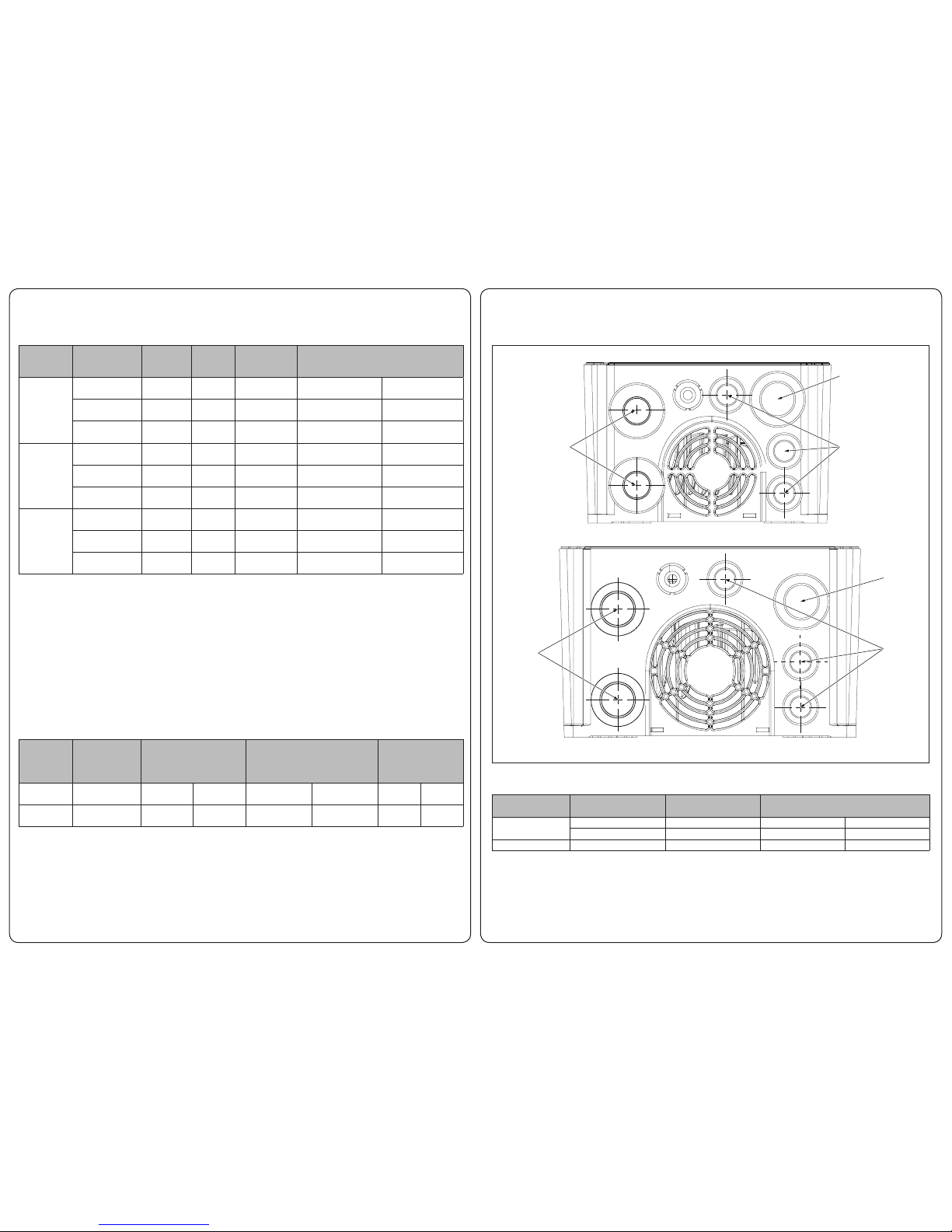
M20x1.5
M25x1.5
M16x1.5
M25x1.5
M16x1.5
M25x1.5
CABLE ENTRIES, MU2 AND MU3 INSTALLATIONS
MU2
MU3
NPT adapter order information
M20: ADEC M20-T12
M25: ADEM M25-T34
 Loading...