


vacon®20 cp/x
ac drives
multipurpose application
manual


vacon • 0
INDEX
Order code: DOC-APP03982+DLUK
Corresponds to application package ACIT1075V110.vcx
1. Multipurpose Application................................................................................. 2
1.1 Specific functions of Vacon Multipurpose application...................................................... 2
1.2 Example of control connections ....................................................................................... 3
1.3 Optional boards ................................................................................................................. 5
1.3.1 Option board installation................................................................................................... 8
2. Description of Groups .................................................................................... 12
2.1 Keypad Reference: Menu REF ........................................................................................ 12
2.2 Monitor group: menu MON ............................................................................................. 13
2.3 Parameter Groups: Menu PAR ....................................................................................... 14
2.3.1 Group Basic Parameters: Menu PAR G1 ........................................................................ 15
2.3.2 Group Advanced Settings: Menu PAR G2........................................................................ 16
2.3.3 Group Analogue inputs: Menu PAR G3 ........................................................................... 18
2.3.4 Group Digital inputs: Menu PAR G4 ............................................................................... 19
2.3.5 Group Digital outputs: Menu PAR G5.............................................................................. 21
2.3.6 Group Analogue outputs: Menu PAR G6 ......................................................................... 22
2.3.7 Group Supervisions: Menu PAR G7................................................................................. 23
2.3.8 Group Motor Control: Menu PAR G8............................................................................... 24
2.3.9 Group Protections: Menu PAR G9................................................................................... 26
2.3.10 Group Autoreset: Menu PAR G10.................................................................................... 28
2.3.11 Group Fieldbus: Menu PAR G11...................................................................................... 29
2.3.12 Group PID-controller: Menu Par G12 ............................................................................. 30
2.3.13 Group temperature measurement: Menu Par G13 ........................................................ 31
2.4 System parameters, Faults and History faults: Menu FLT ............................................ 32
3. Parameter description................................................................................... 36
3.1 Basic Parameters............................................................................................................ 36
3.2 Advanced settings ........................................................................................................... 37
3.3 Analogue inputs............................................................................................................... 46
3.4 Digital inputs ................................................................................................................... 50
3.5 Digital outputs ................................................................................................................. 52
3.6 Analogue Output..............................................................................................................54
3.7 Supervisions .................................................................................................................... 55
3.8 Motor control................................................................................................................... 56
3.9 Protections ...................................................................................................................... 60
3.10 Autoreset ......................................................................................................................... 66
3.11 Fieldbus ........................................................................................................................... 67
3.11.1 Fieldbus mapping............................................................................................................ 68
3.12 PID Control ...................................................................................................................... 71
3.13 Temperature measurement ........................................................................................... 73
4. Fault tracing .................................................................................................. 76
Document ID: DPD00536G
Rev. G
Version release date: 19.6.14
Service support: find your nearest Vacon service center at www.vacon.com

vacon • 1

Multipurpose Application vacon • 2
1. MULTIPURPOSE APPLICATION
The VACON® 20 CP/X drive contains a preloaded application for instant use.
The parameters of this application are listed in chapter 2.3 of this manual and explained in
more detail in chapter 2.
1.1 Specific functions of Vacon Multipurpose application
The Vacon Multipurpose allows flexible use of VACON® 20 CP/X frequency converters.
Features
The drive can be controlled through I/O terminals, a fieldbus or the optional keypad.Two programmable control places and sources for the frequency reference are available, for easy local/remote control.
Frequency reference can be direct (analogue input, preset speeds, motor potentiometer, fieldbus) or controlled by the internal PID regulator.
PID setpoint and actual value are totally programmable. A "sleep" function is available, with
possibility of pressure boost and check of the losses before entering the stand-by state.
All the functionalities can be controlled through a fieldbus.
The motor identification function allows automatic optimization of the voltage/frequency curve,
for a optimal torque response also at low motor speed.
It is possible to install one optional board for I/O expansion.
Service support: find your nearest Vacon service center at www.vacon.com
1
vacon • 3 Multipurpose Application
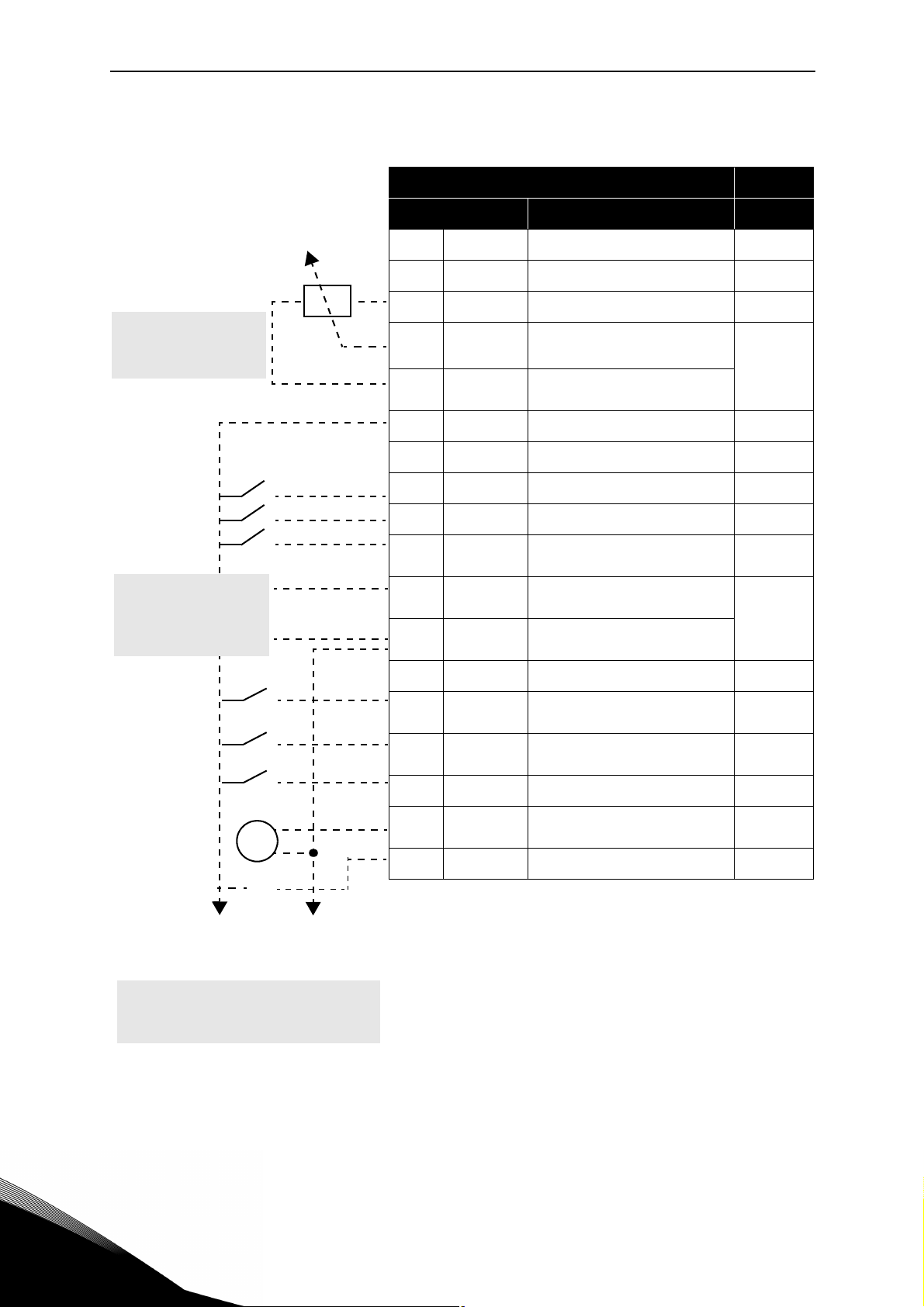
1.2 Example of control connections
Standard I/O terminals
Terminal Signal Default
RS485 Serial bus, negative
A
RS485 Serial bus, positive
B
+10 Vref Reference output
1
Reference potentiometer
1...10 kΩ
PID Actual value
4...20mA/0...10V
(programmable)
AI1+
2
AI1-/GND
3
24Vout 24V aux. voltage
6
DIN COM Digital input common
7
DI1 Digital input 1 Start FWD
8
DI2 Digital input 2 Start REV
9
DI3 Digital input 3
10
AI2+
4
AI2-/GND
5
DO1- Digital Output Common
13
DI4 Digital input 4
14
DI5 Digital input 5
15
Analogue input,
voltage or current
Analogue input common
(current)
Analogue input,
voltage or current*
Analogue input common
(current)
*
Voltage
Preset
Speed B0
Current
Preset
Speed B1
Fault
reset
V
X1
Table 1. Connection example, standard I/O terminals.
To Relay terminals
1 or 2
DI6 Digital input 6 Ramp 2
16
AO1+ Analogue signal (+output)
18
DO1+ Digital output +
20
*
Selectable with DIP switches, see VACON® 20 CP/X
Installation Manual
Output
frequency
Ready
1

Multipurpose Application vacon • 4
From
Standard I/O terminals
From term.
#6
From term.
#3 or #5
FAU LT
Table 2. Connection example, Relay terminals
Relay terminals
Terminal Signal
22 RO1/2 CM
23 RO1/3 NO
24 RO1/1 NC
25 RO1/2 CM
26 RO1/3 NO
Default
Relay output 1 RUN
Relay output 1 FAULT
Service support: find your nearest Vacon service center at www.vacon.com
1

vacon • 5 Multipurpose Application
1.3 Optional boards
One optional I/O expansion board can be installed into the slot on the right side of the drive. The
following boards are supported:
OPTB1: 6 Digital Inputs-Outputs
The first 3 terminals are reserved as digital inputs (DIN7, DIN8, DIN9). The second 3 terminals
can be used as inputs (DIN10, DIN11, DIN12) or digital outputs (EO1, EO2, EO3). The number of
terminals used as input must be declared in parameter P2.24 (hidden if the board is not installed). This number determines the higher value for the selection of the digital input connected to a certain logical function. It also changes the visibility of parameters for the selection of
digital outputs function (P5.9, P5.10, P5.11).
OPTB2: 1 Thermistor Input, 2 Relays Outputs
Response to thermistor fault can be programmed with parameter P9.16. Relays functions can
be programmed with parameters P5.9, P5.10 (hidden if the board is not installed).
OPTB4: 1 Analogue Input, 2 Analogue Outputs
One more input is available as frequency reference. Signal programmable with parameters
P3.9 - 12. Two more outputs are available to monitor motor/drive signals. Outputs are programmable with parameters P6.5 - 12.
Parameters are hidden if the board is not installed.
OPTB5: 3 Relays Outputs
Relays functions can be programmed with parameters P5.9, P5.10, P5.11 (hidden if the board
is not installed).
OPTB9: 5 Digital Inputs, 1 Relay Output
The higher value for the selection of the digital input (DIN7, DIN8, DIN9, DIN10, DIN11) connected to a certain logical function is set to 11. Relay functions can be programmed with parameters P5.9 (hidden if the board is not installed).
OPTBF: 1 Analogue Output, 1 Digital Output, 1 Relay Output
The analogue output can be programmed with parameters P5.5 - 8. The digital output can be
programmed with parameter P5.12. The digital output can be programmed with parameter
P5.9. Parameters are hidden if the board is not installed.
OPTBH: 3 temperature sensors
When the board is installed, the specific menu G13 is visible. Temperature measurement can
be used to set a digital/relay output and/or to trigger a fault. It can also be used as direct frequency reference or as actual value for PID regulation.
1
OPTBK: 4 ASi Outputs , 4 ASi Inputs
ASi outputs are managed as 4 optional digital inputs (DIN7, DIN8, DIN9, DIN10). The higher value for the selection of the digital input connected to a certain logical function is set to 10.
ASi inputs 1-4 are managed as 4 optional outputs (EO1, EO2, EO3, EO4) programmable with
P5.9 - 12.

Multipurpose Application vacon • 6
OPTC3/E3: Profibus DPV1 fieldbus board
Vacon 20CP/X frequency converters can be connected to the PROFIBUS DP network using a
fieldbus board. The converter can then be controlled, monitored and programmed from the
Host system.OPTE3 option board also supports connection from DP Master (class 2) if DP-V1
is enabled. In this case, the Master class 2 can initiate a connection, read and write parameters
using the PROFIdrive Parameter Access service, and close the connection. The PROFIBUS DP
fieldbus is connected to the OPTE3 board using a 5-pin pluggable bus connector. The only difference between OPTE3 and OPTE5 boards is the fieldbus connector.
OPTC4 Lonworks fieldbus board
Vacon 20CP/X frequency converters can be connected to the LonWorks® network using a
fieldbus board. The converter can then be controlled, monitored and programmed from the
Host system.
OPTC5/E5: Profibus DPV1 fieldbus board (D-type connector)
Vacon 20CP/X frequency converters can be connected to the PROFIBUS DP network using a
fieldbus board. The converter can then be controlled, monitored and programmed from the
Host system.OPTE5 option board also supports connection from DP Master (class 2) if DP-V1
is enabled. In this case, the Master class 2 can initiate a connection, read and write parameters
using the PROFIdrive Parameter Access service, and close the connection. he PROFIBUS DP
fieldbus is connected to the OPTE5 board using a 9-pin female sub-D-connector. The only difference between OPTE3 and OPTE5 boards is the fieldbus connector.
OPTC6/E6: CanOpen fieldbus board
Vacon 20CP/X frequency converters can be connected to the CanOpen system using a fieldbus
board. The converter can then be controlled, monitored and programmed from the Host system. Vacon CanOpen Board is connected to the fieldbus through a 5-pin pluggable bus connector (board NXOPTE6).
OPTC7/E7: DeviceNet fieldbus board
Vacon 20CP/X frequency converters can be connected to the DeviceNet using a fieldbus board.
The converter can then be controlled, monitored and programmed from the Host system. Vacon DeviceNet Board is connected to the fieldbus through a 5-pin pluggable bus connector
(board OPTE7).
OPTCI: Modbus TCP fieldbus board
Vacon 20CP/X frequency converters can be connected to Ethernet using an Ethernet fieldbus
board OPTCI. Every appliance connected to an Ethernet network has two identifiers; a MAC address and an IP address. The MAC address (Address format: xx:xx:xx:xx:xx:xx ) is unique to the
appliance and cannot be changed. The Ethernet board's MAC address can be found on the
sticker attached to the board or by using the Vacon IP tool software NCIPConfig. Please find
the software installation at www.vacon.com. In a local network, IP addresses can be defined by
the user as long as all units connected to the network are given the same network portion of
the address. For more information about IP addresses, contact your Network Administrator.
Overlapping IP addresses cause conflicts between appliances.
Service support: find your nearest Vacon service center at www.vacon.com
1

vacon • 7 Multipurpose Application
OPTCP: Profinet fieldbus board
Vacon 20CP/X frequency converters can be connected to Ethernet using an Ethernet fieldbus
board OPTCP. Every appliance connected to an Ethernet network has two identifiers; a MAC
address and an IP address. The MAC address (Address format: xx:xx:xx:xx:xx:xx ) is unique to
the appliance and cannot be changed. The Ethernet board's MAC address can be found on the
sticker attached to the board or by using the Vacon IP tool software NCIPConfig. You can find
the software installation at www.vacon.com. In a local network, IP addresses can be defined by
the user as long as all units connected to the network are given the same network portion of
the address. For more information about IP addresses, contact your Network Administrator.
Overlapping IP addresses cause conflicts between appliances.
OPTCQ: Ethernet IP fieldbus board
Vacon 20CP/X frequency converters can be connected to Ethernet using an EtherNet/IP fieldbus board OPT-CQ. Every appliance connected to an Ethernet network has two identifiers; a
MAC address and an IP address. The MAC address (Address format: xx:xx:xx:xx:xx:xx) is
unique to the appliance and cannot be changed. The EtherNet/IP board's MAC address can be
found on the sticker attached to the board or by using the Vacon IP tool software NCIPConfig.
Please find the software installation at www.vacon.com. In a local network, IP addresses can
be defined by the user as long as all units connected to the network are given the same network
portion of the address. For more information about IP addresses, contact your Network Administrator. Overlapping IP addresses cause conflicts between appliances.
1
Multipurpose Application vacon • 8
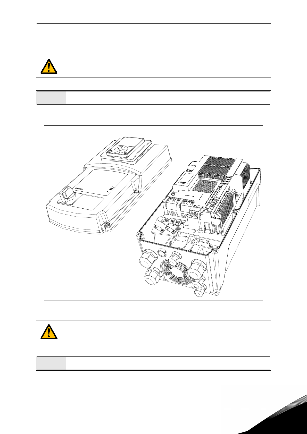
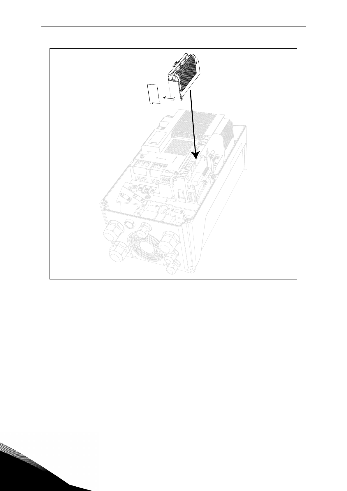
1.3.1 Option board installation
NOTE! It is not allowed to add or replace option boards or fieldbus boards on an AC
drive with the power switched on. This may damage the boards.
1
• Open the cover of the drive.
Figure 1. Opening the main cover, MU3 example.
The relay outputs and other I/O-terminals may have a dangerous control voltage
present even when the drive is disconnected from mains.
2
Service support: find your nearest Vacon service center at www.vacon.com
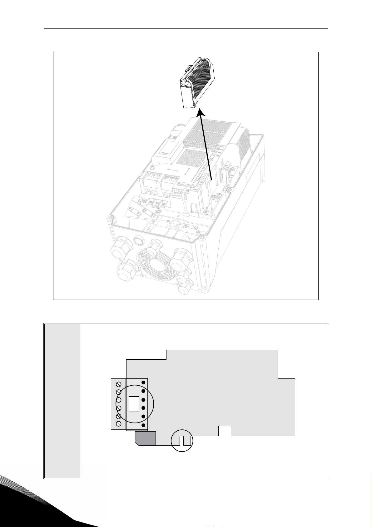
• Remove the option slot cover.
1
vacon • 9 Multipurpose Application
Slot coding
OPT
dv
9116.emf
Figure 2. Removing the option slot cover.
• Make sure that the sticker on the connector of the board says “dv” (dual
voltage). This indicates that the board is compatible with Vacon 20CP/X.
See below:
3
• NOTE: Incompatible boards cannot be installed on Vacon 20CP/X. Compatible boards have a slot coding that enable the placing of the board (see
above).
1
Multipurpose Application vacon • 10
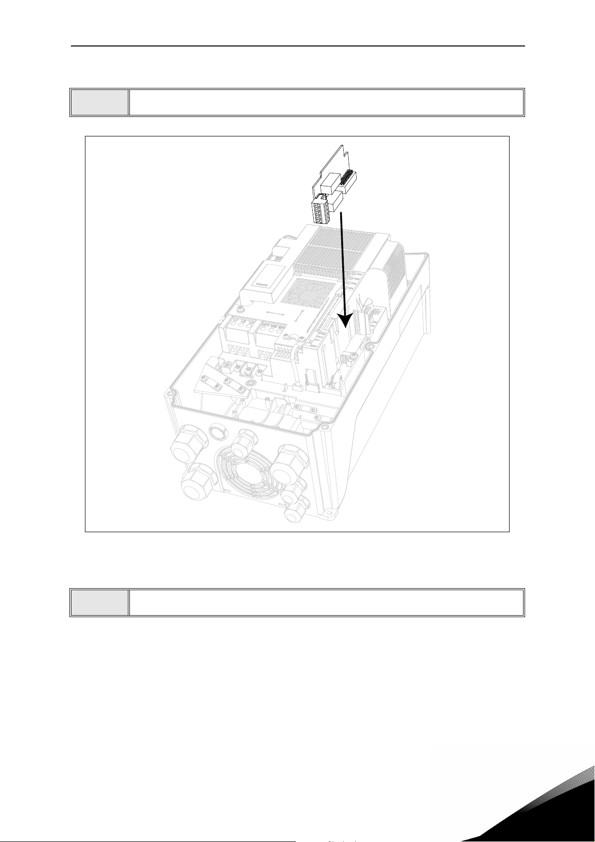
4
• Install the option board into the slot as shown in the picture below.
Figure 3. Option board installation.
• Mount the option slot cover.
5
Service support: find your nearest Vacon service center at www.vacon.com
1
vacon • 11 Multipurpose Application
Figure 4. Mounting of option slot cover: remove the plastic opening for option board termi-
nals.
1

Description of Groups vacon • 12
2. DESCRIPTION OF GROUPS
2.1 Keypad Reference: Menu REF
This menu is automatically entered when pressing the LOC/REM keypad and shows the frequency reference in Local control mode.
The reference is also active when selected as main reference (P1.12=4) or as secondary reference (P2.15=4).
Value is limited between min frequency P1.1 and max frequency P1.2.
In Local mode, or when keypad is the active control place (P1.11=1 or P2.14=1), direction of rotation is determined with P2.23 or by pressing the left or right arrow button.
Service support: find your nearest Vacon service center at www.vacon.com
2

vacon • 13 Description of Groups
2.2 Monitor group: menu MON
VACON® 20 CP/X AC drive provides you with a possibility to monitor the actual values of parameters and signals as well as statuses and measurements. See Table 3 in which the basic
monitoring values are presented.
Code Monitoring value Unit ID Description
V1.1 Output frequency Hz 1 Output frequency to motor
V1.2 Frequency reference Hz 25 Frequency reference to motor control
V1.3 Motor shaft speed rpm 2 Motor speed in rpm
V1.4 Motor Current A 3
V1.5 Motor Torque % 4 Calculated shaft torque
V1.6 Motor Power % 5 Total power consumption of AC drive
V1.7 Motor Voltage V 6
V1.8 Motor temperature % 9 Calculated motor temperature
V1.9 DC-link Voltage V 7
V1.10 Unit temperature °C 8 Heatsink temperature
V1.11 Board temperature °C 1825 Power board temperature
V1.12 Analogue input 1 % 13 Analogue input AI1
V1.13 Analogue input 2 % 14 Analogue input AI2
V1.14 Exp. Analogue input % 1837 Analogue input on OPTB4
V1.15 Analogue output % 26 Analogue output
V1.16 Exp. Analogue out 1 % 1838 Analogue output 1 on OPTB4-BF
V1.17 Exp. Analogue out 2 % 1839 Analogue output 2 on OPTB4
V1.18 DI1, DI2, DI3 15 Digital inputs status
V1.19 DI4, DI5, DI6 16 Digital inputs status
V1.20 DI7, DI8, DI9 1835 Digital inputs on OPTB1 status
V1.21 DI10, DI11, DI12 1836 Digital inputs on OPTB1 status
V1.22 RO1, RO2, DO 17 Digital outputs status
V1.23 EO1, EO2, EO3, EO4 1852 Expansion board digital outputs status
V1.24 Process variable 29 Scaled process variable See P7.10
V1.25 PID setpoint % 20 PID controller setpoint
V1.26 PID error value % 22 PID controller error
V1.27 PID feedback % 21 PID controller actual value
V1.28 PID output % 23 PID controller output
V1.29 Temperature sensor 1 °C or °K 1860 OPTBH sensor 1
V1.30 Temperature sensor 2 °C or °K 1861 OPTBH sensor 1
V1.31 Temperature sensor 3 °C or °K 1862 OPTBH sensor 1
V1.32 ASi board state 1894 OPTBK state
2
NOTE!
Table 3. Monitoring menu items.
Values V1.25-28 are hidden when PID output is not used as frequency reference.
Values V1.14, V1.17 are hidden when OPTB4 expansion board is not installed.
Value V1.16 is hidden when OPTB4-BF expansion board is not installed.
Values V1.20, V1.21 are hidden hidden when no expansion board with available inputs is installed.
Value V1.23 is hidden when no expansion board with available outputs is installed.
Values V1.29, V1.30, V1.31 are hidden when OPTBH expansion board is not installed.
Value V1.32 is hiddend when OPTBK expansion board is not installed.

Description of Groups vacon • 14
2.3 Parameter Groups: Menu PAR
The Multipurpose Application embodies the following parameter groups:
Menu and Parameter group Description
Group Basic Parameters: Menu PAR G1 Basic settings
Group Advanced Settings: Menu PAR G2 Advanced parameter settings
Group Analogue inputs: Menu PAR G3 Analogue input programming
Group Digital inputs: Menu PAR G4 Digital input programming
Group Digital outputs: Menu PAR G5 Digital output programming
Group Analogue outputs: Menu PAR G6 Analogue outputs programming
Group Supervisions: Menu PAR G7 Prohibit frequencies programming
Group Motor Control: Menu PAR G8 Motor control and U/f parameters
Group Protections: Menu PAR G9 Protections configuration
Group Autoreset: Menu PAR G10 Auto reset after fault configuration
Group Fieldbus: Menu PAR G11 Fieldbus data out parameters
Group PID-controller: Menu Par G12 Parameters for PID Controller.
Group Temperature measurement: Menu Par G13
Temperature measurement parameters.
Table 4. Parameter groups
Column explanations:
Code = Location indication on the keypad; Shows the operator the parameter num-
ber.
Parameter= Name of parameter
Min = Minimum value of parameter
Max = Maximum value of parameter
Unit = Unit of parameter value; Given if available
Default = Value preset by factory
ID = ID number of the parameter
Description= Short description of parameter values or its function
= The parameter may be changed only in Stop state
Service support: find your nearest Vacon service center at www.vacon.com
2

vacon • 15 Description of Groups
2.3.1 Group Basic Parameters: Menu PAR G1
Code Parameter Min Max Unit Default ID Description
P1.1 Min frequency 0.00 P1.2 Hz 0.00 101
P1.2 Max frequency P1.1 320.00 Hz 50.00 102
P1.3 Acceleration time 1 0.1 3000.0 s 3.0 103
P1.4 Deceleration time 1 0.1 3000.0 s 3.0 104
P1.5 Current limit
P1.6 Motor nominal voltage 180 500 V 400 110
P1.7
P1.8 Motor nominal speed 24 20000 rpm 1440 112
P1.9 Motor nominal current
P1.10 Motor Cos ϕ 0.30 1.00 0.85 120
P1.11 Control Place 0 2 0 125
P1.12
P1.13 Start function 0 1 0 505
P1.14 Stop function 0 1 0 506
Motor nominal
frequency
Frequency reference
source
0.2 x I
8.00 320.00 Hz 50.00 111
0.2 x I
0 5-7* 0 1819
2 x I
H
H
H
2 x I
A
A
H
I
H
I
H
Minimum allowed frequency reference
Maximum allowed frequency
reference
Defines the time required
for the output frequency to
increase from zero frequency to maximum frequency
Defines the time required
for the output frequency to
decrease from maximum
frequency to zero frequency
Maximum motor current
107
from AC drive
Find this value U
rating plate of the motor.
This parameter sets the
voltage at the field weakening point to 100% * U
Note also used connection
(Delta/Star).
Find this value f
ing plate of the motor.
Find this value nn on the rating plate of the motor.
Find this value In on the rat-
113
ing plate of the motor.
Find this value on the rating
plate of the motor
Run and direction control:
0 = I/O terminals
1 = Keypad
2 = Fieldbus
Selection of reference
source:
0 = AI1
1 = AI2
2 = PID reference
3 = Motor potentiometer
4 = Keypad
5 = Fieldbus
6 = Expansion AI1
7 = Temperature
(*)6 requires expansion
board OPTB4; 7 requires
expansion boad OPTBH.
0=Ramping
1=Flying start
0=Coasting
1=Ramping
on the
n
nMotor
on the rat-
n
.
2

Description of Groups vacon • 16
P1.15 Torque oost 0 1 0 109
P1.16 Show all parameters 0 1 0 115
0 = Not active
1 = Auto torque boost
0 = only Basic
1 = All groups
Table 5. Basic parameters.
2.3.2 Group Advanced Settings: Menu PAR G2
Code Parameter Min Max Unit Default ID Description
Logic = 0:
Start sgn 1 = Start Forward
Start sgn 2 = Start Backward
Logic =1:
Start sgn 1 = Start
Start sgn 2 = Reverse
P2.1 Start/Stop logic 0 3 0 300
P2.2 Preset speed 1 0.00 P1.2 Hz 10.00 105 Multistep speed 1
P2.3 Preset speed 2 0.00 P1.2 Hz 15.00 106 Multistep speed 2
P2.4 Preset speed 3 0.00 P1.2 Hz 20.00 126 Multistep speed 3
P2.5 Preset speed 4 0.00 P1.2 Hz 25.00 127 Multistep speed 4
P2.6 Preset speed 5 0.00 P1.2 Hz 30.00 128 Multistep speed 5
P2.7 Preset speed 6 0.00 P1.2 Hz 40.00 129 Multistep speed 6
P2.8 Preset speed 7 0.00 P1.2 Hz 50.00 130 Multistep speed 7
P2.9 Acceleration time 2 0.1 3000.0 s 10.0 502
P2.10 Deceleration time 2 0.1 3000.0 s 10.0 503
P2.11
P2.12
P2.13 S ramp shape 1 0.0 10.0 s 0.0 500 Rounded speed profile.
P2.14
Accel1 to Accel2 tran-
sition frequency
Decel1 to Decel2 tran-
sition frequency
Control place 2
0.00 P1.2 Hz 0.00 527
0.00 P1.2 Hz 0.00 528
0 2 0 1806
Logic = 2:
Start sgn 1 = Start pulse
Start sgn 2 = Stop pulse
Logic = 3:
Start sgn 1 = Start Forward
(edge)
Start sgn 2 = Start Backward (edge)
Time from 0 to max frequency
Time from 0 to max frequency
Threshold for auto change
from acc1 to acc2
Threshold for auto change
from dec2 to dec1
Alternative control place:
0: I/O terminals
1: Keypad
2: Fieldbus
Service support: find your nearest Vacon service center at www.vacon.com
2

vacon • 17 Description of Groups
Selection of reference
source 2:
0 = AI1
1 = AI2
2 = PID reference
3 = Motor potentiometer
P2.15
P2.16
P2.17
P2.18 Skip range 1 low lim 0.00 P1.2 Hz 0.00 509 0 = Not used
P2.19 Skip range 1 high lim 0.00 P1.2 Hz 0.00 510 0 = Not used
P2.20 Skip range 2 low lim 0.00 P1.2 Hz 0.00 511 0 = Not used
P2.21 Skip range 2 high lim 0.00 P1.2 Hz 0.00 512 0 = Not used
P2.22 Stop button active 0 1 1 114
P2.23 Keypad Reverse 0 1 0 123
P2.24 OPTB1 Digital inputs 3 6 6 1829
P2.25
P2.26 S ramp shape 2 0.0 10.0 s 0.0 501
Frequency reference
source 2
MotorPotentiometer
Ramp
MotorPotent Ref Mem-
ory
Quick Stop decelera-
tion time
0 5-7* 1 1820
1 50 Hz/s 5 331
0 2 0 367
0.1 3000.0 s 2.0 1889
4 = Keypad
5 = Fieldbus
6 = Expansion AI1
7 = Temperature
(*)6 requires expansion
board OPTB4; 7 requires
expansion boad OPTBH.
Rate of change in the motor
potentiometer reference
when increased or
decreased.
Motor potentiometer frequency reference reset
logic.
0 = No reset
1 = Reset if stopped or powered down
2 = Reset if powered down
0 = Limited function of Stop
button
1 = Stop button always
enabled
Motor rotation when control place is keypad
0 = Forward
1 = Reverse
Number of terminals used
as digital inputs.
The parameter is visible
only when OPTB1 board is
installed
Time from max frequency to
0
Rounded speed profile
when Acc/Dec 2 is active.
2
NOTE!
Table 6. Advanced settings group.
Visibility of the group depends on P1.16.

Description of Groups vacon • 18
2.3.3 Group Analogue inputs: Menu PAR G3
Code Parameter Min Max Unit Default ID Description
P3.1 AI1 signal range 0 1 0 379
P3.2 AI1 custom min -100.00 100.00 % 0.00 380
P3.3 AI1 custom max -100.00 300.00 % 100.00 381 Custom range max setting
P3.4 AI1 filter time 0.0 10.0 s 0.1 378
P3.5 AI2 signal range 0 1 1 390
P3.6 AI2 custom min -100.00 100.00 % 0.00 391 See P3.2
P3.7 AI2 custom max -100.00 300.00 % 100.00 392 See P3.3
P3.8 AI2 filter time 0.0 10.0 s 0.1 389 See P3.4
P3.9 Exp. AI signal range 0 1 0 1841
P3.10
P3.11 Exp. AI custom max -100.00 300.00 % 100.00 1843
P3.12 Exp. AI filter time 0.0 10.0 s 0.1 1844
Exp. AI custom
min
-100.00 100.00 % 0.00 1842
0 = 0…10V / 0…20mA
1 = 2…10V / 4…20mA
Custom range min setting
20% = 4-20 mA/2-10 V
Filter time for analogue
input
0 = 0…10V / 0…20mA
1 = 2…10V / 4…20mA
0 = 0…10V / 0…20mA
1 = 2…10V / 4…20mA
Custom range min signal
level
Custom range max signal
level
Filter time for analogue
input
NOTE!
Table 7. Analogue inputs group.
Visibility of the group depends on P1.16. Parameters P3.9 - P3.12 are shown only
when expansion board OPTB4 is installed.
Service support: find your nearest Vacon service center at www.vacon.com
2

vacon • 19 Description of Groups
2.3.4 Group Digital inputs: Menu PAR G4
Code Parameter Min Max Unit Default ID Description
Start signal 1 when control
place is I/O 1 (FWD)
See P2.1 for function.
0 = not used
P4.1 Start signal 1 0 6* 1 403
P4.2 Start signal 2 0 6* 2 404
P4.3 Reverse 0 6* 0 412
P4.4 External fault close 0 6* 0 405
P4.5 External fault open 0 6* 0 406
P4.6 Fault reset 0 6* 5 414 Resets all active faults
P4.7 Run enable 0 6* 0 407
P4.8 Preset speed B0 0 6* 3 419
P4.9 Preset speed B1 0 6* 4 420
P4.10 Preset speed B2 0 6* 0 421
P4.11 Sel Accel/Decel 2 0 6* 6 408
P4.12
P4.13
P4.14 Sel Control Place 2 0 6* 0 1813
P4.15 Sel Freq reference 2 0 6* 0 1814
P4.16 Sel PID setpoint 2 0 6* 0 431
P4.17 Quick Stop open 0 6* 0 1888
P4.18 Stop Mode Activation 0 2 0 1895
MotorPotent increase
speed
MotorPotent decrease
speed
06* 0418
06* 0417
1 = DIN1
2 = DIN2
3 = DIN3
4 = DIN4
5 = DIN5
6 = DIN6
Start signal 2 when control
place is I/O 1 (REV).
See P2.1 for function.
See P4.1 for selections.
Independent from P2.1
See P4.1 for selections
Fault if signal high
See P4.1 for selections
Fault is signal low
See P4.1 for selections
Must be on to set drive in
Ready state
Binary selector for Preset
speeds (0-7).
Binary selector for Preset
speeds (0-7).
Binary selector for Preset
speeds (0-7).
Activates ramp 2
See P4.1 for selections
Reference increase
See P4.1 for selections
Reference decrease
See P4.1 for selections
Activates control place 2
See P4.1 for selections
Activates reference 2
See P4.1 for selections
Activates setpoint 2
See P4.1 for selections
If configured, low signal activates stop with specific ramp.
See P4.1 for selections.
NOTE: quick stop function
must be enabled with
P4.18=1
0: normal
1: quick stop
2: accurate stop (from Start
signal 1)
2
Table 8. Digital inputs parameters.

Description of Groups vacon • 20
(*)The maximum value is higher when an optional board with digital inputs is
NOTE!
installed (see chapter 1.3 and Table 9 for more details). Parameter is automatically reset if value is greater than present limit.
NOTE!
Table 9. Maximum value for digital input selection depending on installed option board.
Visibility of the group depends on P1.16.
Option board
installed
OPTB1 12 DIN7, DIN8, DIN9, DIN10, DIN11, DIN12
OPTB9 7 DIN7
OPTBK 10 DIN7, DIN8, DIN9, DIN10
Maximum value for
digital input selection
Digital inputs available
Service support: find your nearest Vacon service center at www.vacon.com
2

vacon • 21 Description of Groups
2.3.5 Group Digital outputs: Menu PAR G5
Code Parameter Min Max Unit Default ID Description
Function selection for RO1:
0 = Not used
1 = Ready
2 = Run
3 = General fault
4 = General fault inverted
5 = Warning
6 = Reversed
P5.1 Relay output 1 content 0 14 2 313
P5.2 Relay output 2 content 0 14 3 314 See P5.1
P5.3 Digital output content 0 14 1 312 See P5.1
P5.4 Relay output 1 on delay 0.00 320.00 s 0.00 458 ON delay for relay
P5.5 Relay output 1 off delay 0.00 320.00 s 0.00 459 OFF delay for relay
P5.6 Relay output 1 inversion 0 1 0 1804
P5.7 Relay output 2 on delay 0.00 320.00 s 0.00 460 See P5.4
P5.8 Relay output 2 off delay 0.00 320.00 s 0.00 461 See P5.5
P5.9 Exp. EO1 content 0 14 0 1826
P5.10 Exp. EO2 content 0 14 0 1827 See P5.9
P5.11 Exp. EO3 content 0 14 0 1828 See P5.9
P5.12 Exp. EO4 content 0 14 0 1872 See P5.9
7 = At speed
8 = Output freq. supervision
9 = Output current superv.
10 = Analogue input superv.
11 = Fieldbus 1
12 = Fieldbus 2
13 = External brake
14 = Temperature supervision (OPTBH)
0 = no inversion
1 = inverted
Parameter visible when a I/
O expansion board is
installed. See P5.1 for
selection
2
NOTE!
Table 10. Digital outputs parameters.
Visibility of the group depends on P1.16.
P5.9 is visible when OPTB2,OPTB5, OPTB9 or OPTBF is installed (first relay EO1).
P5.10 is visible when OPTB2 or OPTB5 is installed (second relay EO2).
P5.11 is visible when OPTB5 is installed (third relay EO3).
P5.9, P5.10, P5.11 are also visible when OPTB1 is installed and some outputs
have been set with P2.24 (digital outputs EO1, EO2, EO3).
P5.12 is visible when OPTBF is installed(digital output EO4).
Selection 14 as output function requires OPTBH board installed.
P5.9, P5.10, P5.11, P5.12 are also visible when OPTBK is installed (EO1,2,3,4 corresponding to ASi inputs 1,2,3,4).

Description of Groups vacon • 22
2.3.6 Group Analogue outputs: Menu PAR G6
Code Parameter Min Max Unit Default ID Description
0 = Not used (fixed 100%)
1 = Freq. reference (0-fmax)
2 = Output freq. (0 -fmax)
3 = Motor speed (0 - Speed
P6.1
P6.2
P6.3 Analogue output scale 0,0 1000,0 % 100.0 311 Scaling factor
P6.4
P6.5 Exp. AO1 function 0 8 2 1844 See P5.1
P6.6 Exp. AO1 minimum 0 1 0 1845
P6.7 Exp. AO1 Output scale 0,0 1000,0 % 100.0 1846 Scaling factor
P6.8 Exp. AO1 filter time 0.00 10.00 s 0.10 1847
P6.9 Exp. AO2 function 0 8 2 1848 See P6.1
P6.10 Exp. AO2 minimum 0 1 0 1849
P6.11 Exp. AO2 Output scale 0,0 1000,0 % 100.0 1850 Scaling factor
P6.12 Exp. AO2 filter time 0.00 10.00 s 0.10 1851
Analogue output
function
Analogue output
minimum
Analogue output filter
time
0 8 2 307
0 1 0 310
0.00 10.00 s 0.10 308
max)
4 = Output current (0-I
5 = Motor torque (0-T
6 = Motor power (0-P
7 = PID output (0-100%)
8 = Filedbus(0-10000)
0 = 0V
1 = 2V
Filtering time of analogue output signal.
0 = No filtering
0 = 0 mA
1 = 4 mA
Filtering time of analogue output signal.
0 = No filtering
0 = 0 mA
1 = 4 mA
Filtering time of analogue output signal.
0 = No filtering
nMotor
nMotor
nMotor
)
)
)
Table 11. Analogue outputs parameters.
Visibility of the group depends on P1.16.
Parameters P6.5 - P6.18 are shown only when expansion board OPTB4 or OPTBF
NOTE!
is installed.
Parameters P6.9 - P6.12 are shown only when expansion board OPTB4 is
installed.
Service support: find your nearest Vacon service center at www.vacon.com
2

vacon • 23 Description of Groups
2.3.7 Group Supervisions: Menu PAR G7
Code Parameter Min Max Unit Default ID Description
P7.1
P7.2
P7.3
P7.4 AnalogIn Supv Signal 0 2 0 356
P7.5 AnalogIn Supv ON level 0.00 100.00 % 80.00 357 ON threshold AI supervision
P7.6
P7.7
P7.8
P7.9
P7.10 Process Source Select 0 5 2 1036
P7.11
P7.12 Process Max Value 0.0 3276.7 100.0 1034
Frequency
supervision 1
Frequency supervision
value
Current supervision
value
AnalogIn Supv OFF
level
External brake open
frequency
External brake open
current
External brake close
frequency
Process Val Decim
Digits
02 0315
0.00 P1.2 Hz 0.00 316
0.00
0.00 100.00 % 40.00 358 OFF threshold AI supervision
0.00 10.00 Hz 2.00 1808
0.0 100.0 % 30.0 1810
0.00 10.00 Hz 2.00 1809
0 3 1 1035 Decimals on display
2 x I
A0.001811
H
0 = not used
1 = Low limit
2 = High limit
Output frequency supervision
threshold
Current supervision threshold
0 = AI1
1 = AI2
2 = AIE (if option OPTB4)
Frequency threshold for
brake open
Current threshold for brake
open
Frequency threshold for
brake close (Start = 0)
Selection of variable proportional to process:
0 = PID feedback value
1 = Output frequency
2 = Motor speed
3 = Motor torque
4 = Motor power
5 = Motor current
Process display max value( it
depends on P7.11: with zero
decimal digit the max value
is 32767; with 1 decimal digit
the max value is 3276.7 )
2
NOTE!
Table 12. Supervision parameters.
Visibility of the group depends on P1.16.

Description of Groups vacon • 24
2.3.8 Group Motor Control: Menu PAR G8
Code Parameter Min Max Unit Default ID Description
P8.1 Motor control mode(*) 0 1 0 600
P8.2 Field Weakening Point 30.00 320.00 Hz 50.00 602
P8.3
P8.4 U/f ratio selection(*) 0 2 0 108
P8.5
P8.6
P8.7
P8.8 Switching frequency 1.5 16.0 kHz 6.0 601
P8.9 Brake chopper 0 2 0 504
P8.10
P8.11 DC brake current
P8.12
P8.13
P8.14
P8.15
P8.16 Motor Identification 0 1 0 631
Voltage at Field Weak-
ening Point
U/f curve midpoint
frequency(*)
U/f curve midpoint
voltage(*)
Output voltate at zero
frequency (*)
Brake chopper thresh-
old
DC braking time at
stop
Frequency to start DC
braking at ramp stop
DC braking time at
start
Motor stator voltage
drop(*)
10.00 200.00 % 100.00 603
0.00 P8.2 Hz 50.00 604
0.00 P8.3 % 100.00 605
0.00 40.00 % 0.00 606
600 900 V 765 1807
0.3 x I
0.00 600.00 s 0.00 508
0.10 10.00 Hz 1.50 515
0.00 600.00 s 0.00 516
0.00 100.00 % 0.00 662
2 x I
H
A
H
I
H
507
0 = Frequency control
1 = Speed control
Field weakening point frequency
Voltage at FWP as % of
Motor nominal voltage
0 = linear
1 = quadratic
2 = programmable
Midpoint frequency for programmable U/f curve
Midpoint voltage for programmable U/f curve
Voltage at 0,00 Hz as % of
Motor nominal voltage
Motor noise can be minimized using a high switching frequency. Increasing
the switching frequency
reduces the capacity of the
drive. It is recommended to
use a lower frequency
when the motor cable is
long in order to minimize
capacitive currents in the
cable.
0 = Disabled
1 = Enabled in RUN
2 = Enabled in READY
DC-link voltage to start
chopper.
Defines the current
injected into the motor during DC-braking.
0 = Disabled
Determines if braking is
ON or OFF and the braking
time of the DC-brake when
the motor is stopping.
The output frequency at
which the DC-braking is
applied.
This parameter defines the
time for how long DC current is fed to motor before
acceleration starts.
Voltage drop on the motor
windings as % of Motor
nominal voltage
0 = not active
1 = standstill identification
(to activate, RUN command within 20s)
Service support: find your nearest Vacon service center at www.vacon.com
2

vacon • 25 Description of Groups
P8.17
P8.18
P8.19
NOTE!
NOTE!
Disable overvoltage
regulator
Disable undervoltage
regulator
Disable switching freq
regulator
Table 13. Motor control parameters.
0 1 0 1853
0 1 0 1854
0 1 0 1855
(*) Parameter is automatically set by motor identification.
Visibility of the group depends on P1.16.
0 = Enabled
1 = Disabled
0 = Enabled
1 = Disabled
0 = Enabled
1 = Disabled
2

Description of Groups vacon • 26
2.3.9 Group Protections: Menu PAR G9
NOTE!
Parameters of Motor thermal protection (P9.11 to P9.14 and P9.21-P9.22)
The motor thermal protection is to protect the motor from overheating. The drive is capable of
supplying higher than nominal current to the motor. If the load requires this high current there
is a risk that the motor will be thermally overloaded. This is the case especially at low frequencies. At low frequencies the cooling effect of the motor is reduced as well as its capacity. If the
motor is equipped with an external fan the load reduction at low speeds is small.
The motor thermal protection is based on a calculated model and it uses the output current of
the drive to determine the load on the motor.
The motor thermal protection can be adjusted with parameters. The thermal current I
fies the load current above which the motor is overloaded. This current limit is a function of the
output frequency.
The thermal stage of the motor can be monitored on the control keypad display. See chapter 1.
Visibility of the group depends on P1.16.
speci-
T
If you use long motor cables (max. 100m) together with small drives (≤1.5 kW) the
motor current measured by the drive can be much higher than the actual motor
current due to capacitive currents in the motor cable. Consider this when setting up
the motor thermal protection functions.
The calculated model does not protect the motor if the airflow to the motor is
reduced by blocked air intake grill. The model starts from zero if the control board is
powered off.
Parameters of Stall protection (P9.4 to P9.6)
The motor stall protection protects the motor from short time overload situations such as one
caused by a stalled shaft. The reaction time of the stall protection can be set shorter than that
of motor thermal protection. The stall state is defined with two parameters, P9.5 (
and P9.6 (
rent limiter has reduced the output frequency below the P9.6 for the time P9.5 than the set limit
the stall state is true. There is actually no real indication of the shaft rotation. Stall protection
is a type of overcurrent protection.
Parameters of Underload protection (P9.7 to P9.10)
The purpose of the motor underload protection is to ensure that there is load on the motor
when the drive is running. If the motor loses its load there might be a problem in the process,
e.g. a broken belt or a dry pump.
Motor underload protection can be adjusted by setting the underload curve with parameters
P9.8 (Underload protection: Field weakening area load) and P9.9 (
frequency load
Stall frequency limit). If the current is as high as the P1.5 (Current Limit) and the cur-
If you use long motor cables (max. 100m) together with small drives (≤1.5 kW) the
motor current measured by the drive can be much higher than the actual motor
current due to capacitive currents in the motor cable. Consider this when setting up
the motor thermal protection functions.
Underload protection: Zero
), see below. The underload curve is a squared curve set between the zero fre-
Stall time)
Service support: find your nearest Vacon service center at www.vacon.com
2

vacon • 27 Description of Groups
quency and the field weakening point. The protection is not active below 5Hz (the underload
time counter is stopped).
The torque values for setting the underload curve are set in percentage which refers to the
nominal torque of the motor. The motor's name plate data, parameter motor nominal current
and the drive's nominal current I
are used to find the scaling ratio for the internal torque val-
L
ue. If other than nominal motor is used with the drive, the accuracy of the torque calculation
decreases.
If you use long motor cables (max. 100m) together with small drives (≤1.5 kW) the
motor current measured by the drive can be much higher than the actual motor
current due to capacitive currents in the motor cable. Consider this when setting up
the motor thermal protection functions.
Code Parameter Min Max Unit Default ID Description
0 = No action
Response to 4mA
P9.1
P9.2
P9.3 Earth fault protection 0 2 2 703
P9.4 Motor stall protection 0 2 1 709 See P9.3
P9.5 Motor stall delay 0.0 300.0 s 5.0 711
P9.6 Motor stall min freq 0.10 320.00 Hz 15.00 712
P9.7 Underload protection 0 2 0 713 See P9.3
P9.8
P9.9
P9.10 Underload time 1.0 300.0 s 20.0 716
P9.11
P9.12
P9.13
reference fault
(< 4mA)
4mA fault detection
time
Underload load curve
at nominal freq
Underload load curve
at zero freq
Thermal protection of
the motor
Motor ambient
temperature
Motor cooling factor at
zero speed
04 1700
0.0 10.0 s 0.5 1430 Time limit
10.0 150.0 % 50.0 714
5.0 150.0 % 10.0 715
0 2 2 704 See P9.3
-20 100 °C 40 705 Ambient temperature in °C
0.0 150.0 % 40.0 706
1 = Warning
2 = Fault
3 = Warning if Start active
4 = Fault if Start active
0 = No action
1 = Warning
2 = Fault
This is the maximum time
allowed for a stall stage.
For a stall state to occur, the
output frequency must have
remained below this limit for
a certain time.
This parameter gives the
value for the minimum
torque allowed when the output frequency is above the
field weakening point.
This parameter gives value
for the minimum torque
allowed with zero frequency.
This is the maximum time
allowed for an underload
state to exist.
Defines the cooling factor at
zero speed in relation to the
point where the motor is running at nominal speed without external cooling.
2

Description of Groups vacon • 28
The time constant is the time
P9.14
P9.15
P9.16 Thermistor fault 0 2 2 732
P9.17 Parameter lock 0 1 0 1805
P9.18
P9.19
P9.20
P9.21
P9.22
Motor thermal time
constant
Response to fieldbus
fault
Response to STO
disable
Response to input
phase fault
Input phase fault max
ripple
Motor temp intial
mode
Motor temp
inital value
1 200 min 45 707
0 2 2 733 See P9.3
03 11876
0 2 2 1877 See P9.3
0 75 0 1893
02 21891
0100%331892
within which the calculated
thermal stage has reached
63% of its final value.
See P9.3
Available only if OPTB2
option board is installed.
0 = Edit enabled
1 = Edit disabled
0 = No action
1 = Warning
2 = Fault, not stored in history menu
3 = Fault, stored in history
menu
0 = internal value
1 = max sensivity ->
75 = min sensivity
0 = start from minimum
1 = start from costant value
2 = start from last value
Initial value(P9.21 = 1) or factor for last previous
value(P9.21 = 2)
Table 14. Protections settings
2.3.10 Group Autoreset: Menu PAR G10
Code Parameter Min Max Unit Default ID Description
P10.1 Automatic fault reset 0 1 0 731
P10.2 Wait time 0.10 10.0 s 0.50 717
P10.3 Trial time 0.00 60.0 s 30.00 718
P10.4 Automatic reset tries 1 10 3 759
P10.5 Start function 0 2 0 719
Table 15. Autoreset settings.
0 = Disabled
1 = Enabled
Wait time before the first
reset is executed.
When the trial time has
elapsed, and the fault is still
active, the drive will trip to
fault.
NOTE: Total number of trials
(irrespective of fault type)
The start mode for Automatic
reset is selected with this
parameter:
0 = Ramp
1 = Flying start
2 = According to par. P1.13
NOTE!
Service support: find your nearest Vacon service center at www.vacon.com
Visibility of the group depends on P1.16.
2

vacon • 29 Description of Groups
2.3.11 Group Fieldbus: Menu PAR G11
Code Parameter Min Max Unit Default ID Description
Variable mapped on PD1:
0 = Output current
1 = Motor speed
2 = Motor current
3 = Motor voltage
4 = Motor torque
5 = Motor power
6 = DC-link voltage
P11.1
P11.2
P11.3
P11.4
P11.5
P11.6
P11.7
P11.8
P11.9 FB Aux CW selection 0 5 0 1821
P11.10
P11.11
P11.12
ProcessDataOut 1
selection
ProcessDataOut 2
selection
ProcessDataOut 3
selection
ProcessDataOut 4
selection
ProcessDataOut 5
selection
ProcessDataOut 6
selection
ProcessDataOut 7
selection
ProcessDataOut 8
selection
FB PID setpoint
selection
FB PID actual
selection
FB AnalogueOut cntrl
selection
0 16 0 852
0 16 1 853
0 16 2 854
0 16 4 855
0 16 5 856
0 16 3 857
0 16 6 858
0 16 7 859
0 5 1 1822
0 5 2 1823
0 5 3 1824
7 = Active fault code
8 = Analogue AI1
9 = Analogue AI2
10 = Digital inputs state
11 = PID feedback value
12 = PID setpoint
13 = Analogue AI3
14 = Temperature 1
15 = Temperature 2
16 = Temperature 3
Variable mapped on PD2. See
P11.1
Variable mapped on PD3. See
P11.1
Variable mapped on PD4. See
P11.1
Variable mapped on PD5. See
P11.1
Variable mapped on PD6. See
P11.1
Variable mapped on PD7. See
P11.1
Variable mapped on PD8. See
P11.1
PDI for Aux CW
0 = Not used
1 = PDI1
2 = PDI2
3 = PDI3
4 = PDI4
5 = PDI5
PDI for PID Setpoint
See P11.9
PDI for PID Feedback
See P11.9
PDI for Analogue Out CTRL
See P11.9
2
NOTE!
Table 16. Fieldbus data mapping.
Visibility of the group depends on P1.16.
Selection 13 as data out requires board OPTB4 installed.
Selections 14, 15, 16 as data out require board OPTBH installed.

Description of Groups vacon • 30
2.3.12 Group PID-controller: Menu Par G12
Code Parameter Min Max Unit
P12.1 Setpoint source 0 3 0 332
P12.2 PID setpoint 1 0.0 100.0 % 50.0 167 Fixed setpoint 1
P12.3 PID setpoint 2 0.0 100.0 % 50.0 168 Fixed setpoint 2
P12.4 Feedback source 0 4 0 334
P12.5 Feedback minimum 0.0 50.0 % 0.0 336 Value at minimum signal
P12.6 Feedback maximum 10.0 300.0 % 100.0 337 Value at maximum signal
P12.7 PID controller P gain 0.0 1000.0 % 100.0 118
P12.8 PID controller I-time 0.00 320.00 s 10.00 119
P12.9 PID controller D-time 0.00 10.00 s 0.00 132
P12.10 Error value inversion 0 1 0 340
P12.11 PID error limit 0.0 100.0 % 100.0 1812 Limit on error
P12.12 Sleep frequency 0.00 P1.2 Hz 0.00 1016
P12.13 Sleep time delay 0 3600 s 30 1017
P12.14 Wake-up limit 0.0 100.0 % 5.0 1018
P12.15 Sleep setpoint boost 0.0 50.0 % 10.0 1815 Referred to setpoint
P12.16 Sleep boost time 0 60 s 10 1816 Boost time after P12.13
P12.17 Sleep max loss 0.0 50.0 % 5.0 1817 Referred to feedback after boost
P12.18 Sleep loss check time 1 300 s 30 1818 After boost time P12.16
Defau
lt
ID Description
0 = PID setpoint 1/2
1 = AI1
2 = AI2
3 = Fieldbus
0 = AI2
1 = AI1
2 = Fieldbus
3 = AI1- AI2
4 = Temperature(OPTBH)
If the value of the parameter is
set to 100% a change of 10% in
the error value causes the controller output to change by 10%.
If this parameter is set to 1,00
second a change of 10% in the
error value causes the controller output to change by 10.00%/
s.
If this parameter is set to 1,00
second a change of 10% in the
error value during 1.00 s causes
the controller output to change
by 10.00%.
0 = Normal (Feedback < Setpoint
-> Increase PID output)
1 = Inverted (Feedback < Setpoint ->
Drive goes to sleep mode when
the output frequency stays
below this limit for a time
greater than that defined by
parameter P12.13.
The minimum amount of time
the frequency has to remain
below the Sleep level before the
drive is stopped.
Defines the level for the PID
feedback value wake-up.
Decrease PID output
)
Table 17. PID controller parameters.
NOTE!
Service support: find your nearest Vacon service center at www.vacon.com
This group is hidden when PID output is not used as frequency reference.
2

vacon • 31 Description of Groups
2.3.13 Group temperature measurement: Menu Par G13
Code Parameter Min Max Unit
P13.1 Temperature unit 0 1 0 1863
P13.2
P13.3 Supervision mode 0 2 1 1864
P13.4 Fault mode 0 2 0 1865
P13.5 Supervision level
P13.6 Fault level
P13.7 Superv/fault Hysteresis 0.0 50.0
P13.8
P13.9
P13.10
Superv/Fault sensor
select
Refer/Actual sensor
select
Min Ref/Actual
temperature
Max Ref/Actual
temperature
0 6 0 1873
-30.0
223.2
-30.0
223.2
-30.0
223.2
-30.0
223.2
200.0
473.2°C°K
200.0
473.2°C°K
0 6 0 1869
200.0
473.2°C°K
200.0
473.2°C°K
Defau
lt
80.0 1867 Threshold for supervision
100.0 1866 Threshold for fault
°C
2.0 1868 Hysteresis for state change
°K
0.0 1870
100.0 1871
ID Description
0 = °C
1 = °K
0= T1
1= T2
2= T1 + T2
3= T3
4= T3 + T1
5= T3 + T2
6= T3 + T2 + T1
0: not used
1: over threshold
2: below threshold
0: not used
1: over threshold
2: below threshold
0= T1
1= T2
2= T3
3= max(T1,T2)
4= min(T1,T2)
5= max(T1, T2, T3)
6= min(T1, T2, T3)
Temperature for min reference/
actual
Temperature for max reference/
actual
2
NOTE!
Table 18. Temperature measurement parameters.
This group is hidden when board OPTBH is not installed.

Description of Groups vacon • 32
2.4 System parameters, Faults and History faults: Menu FLT
Code Parameter Min Max Unit
V1.1 API system SW ID 2314
V1.2 API system SW version 835
V1.3 Power SW ID 2315
V1.4 Power SW version 834
V1.5 Application ID 837
V1.6 Application revision 838
V1.7 System load 839
When no fieldbus board has been installed, the following values are visible:
V2.1 Communication status 808
V2.9 Last communication fault 816
P2.2 Fieldbus protocol 0 1 0 809
P2.3 Slave address 1 255 1 810
P2.4 Baud rate 0 8 5 811
P2.6 Parity type 0 2 0 813
P2.7 Communication time out 0 255 s 0 814
P2.8 Reset communication status 0 1 0 815
When OPTE6 (CANopen) option board has been installed, the following values are visible:
V2.1
CANope communication sta-
tus
Defa
ult
ID Description
14004
Status of Modbus
communication.
Format: xx.yyy
where xx = 0 - 64
(Number of error
messages) yyy = 0 999 (Number of good
messages)
The fault code related to the
last counted bad messages is
shown:
1 = Illegal function
2 = Illegal address
3 = Illegal data value
4 = Illegal slave device
53 = USART receive fault
(parity error/ frame error/
USART buffer overflow)
90 = Receive buffer overflow
100 = Frame CRC Error
101 = Ring buffer overflow
0 = Not used
1 = Modbus used
0 = 300
1 = 600
2 = 1200
3 = 2400
4 = 4800
5 = 9600
6 = 19200
7 = 38400
8 = 57800
0 = None
1 = Odd
2 = Even
Table 19. System parameters, Faults and History faults.
Service support: find your nearest Vacon service center at www.vacon.com
2

vacon • 33 Description of Groups
P2.2 CANopen operation mode 1 2 1 14003
P2.3
P2.4 CANopen baud rate 1 8 6 14002
When OPTE7 (DeviceNet) option board has been installed, the following values are visible:
V2.1
P2.2 Output assembly type 20 111 21 14012
P2.3 MAC ID 0 63 63 14010
P2.4 Baud Rate 1 3 1 14011
P2.5 Input assembly type 70 117 71 14013
When OPTE3/E5(Profibus) option board has been installed, the following values are visible:
V2.1
P2.2 Fieldbus protocol 14023
P2.3 Active protocol 14024
P2.4 Active baud rate 14025
P2.5 Telegram type 14027
P2.6 Operate mode 1 3 1 14021
P2.7 Slave address 2 126 126 14020
When OPTC4 (Lonworks) option board has been installed, the following values are visible:
P2.1 Service PIN 0 0 14217
P2.1 Sensor 1 type 0 6 0 14072
P2.2 Sensor 2 type 0 6 0 14073 See P2.1
P2.3 Sensor 3 type 0 6 0 14073 See P2.1
V3.1 MWh counter 827
V3.2 Power on day counter 828
V3.3 Power on hour counter 829
V3.4 RUN day counter 840
V3.5 RUN hour counter 841
V3.6 Fault conter 842
V3.7
P4.2 Restore factory defaults 0 1 0 831
P4.3 Password 0 9999
P4.4 Time for keypad backlight 0 99 min 5 833
CANopen Node ID
DeviceNet communication
status
Profibus communication sta-
tus
When OPTBH option board has been installed, the following values are visible:
Panel parameter set status
monitor
1 127 1 14001
14014
14022
Other information:
000
832
0
Broadcasts a service pin message to the network.
0 = No Sensor
1 = PT100
2 = PT1000
3 = Ni1000
4 = KTY84
5 = 2 x PT100
6 = 3 x PT100
Hidden when PC is connected
1 = Restore factory defaults
for all parameters
2
Table 19. System parameters, Faults and History faults.

Description of Groups vacon • 34
1= Upload all parameters to
Keypad
P4.5 Save parameters to Keypad 0 1 0
P4.6
F5.x Active fault menu 0 9 Hidden when PC is connected
F6.x Fault history menu 0 9 Hidden when PC is connected
Download parameters from
Keypad
01 0
Hidden when PC is connected.
This function works properly
only with drive supplied.
1= Download all parameters
to Keypad
Hidden when PC is connected.
This function works properly
only with drive supplied.
Table 19. System parameters, Faults and History faults.
Service support: find your nearest Vacon service center at www.vacon.com
2

vacon • 35 Description of Groups
2

Parameter description vacon • 36
3. PARAMETER DESCRIPTION
Due to its user-friendliness and simplicity of use, the most parameters only require a basic description which is given in the parameter tables in chapter 2.2.
In this chapter, you will find additional information on certain most advanced parameters.
Should you not find the information you need contact your distributor.
3.1 Basic Parameters
P1.1 MIN FREQUENCY
Minimum frequency reference.
NOTE: if motor current limit is reached, actual output frequency might be lower than parameter. If this is not acceptable, stall protection should be activated.
P1.2 M
Maximum frequency reference.
P1.3 A
Ramp time, referred to variation from zero frequency to max frequency.
A second acceleration time is available in P2.5.
P1.4 D
Ramp time, referred to variation from max frequency to zero.
A second deceleration time is available in P2.6.
P1.5 C
This parameter determines the maximum motor current from the AC drive. The parameter
value range differs from size to size.
When the current limit is active the drive output frequency is decreased.
NOTE: This is not an overcurrent trip limit.
P1.11 C
AX FREQUENCY
CCELERATION TIME 1
ECELERATION TIME 1
URRENT LIMIT
ONTROL PLACE
Run and direction control. A second control place is programmable in P2.10.
0: I/O terminals
1: Keypad
2: Fieldbus
P1.12 F
Defines the source of frequency reference. A second reference source is programmable in
P2.10.
0: Analogue input AI1
1: Analogue input AI2
2: PID control
Service support: find your nearest Vacon service center at www.vacon.com
REQUENCY REFERENCE SOURCE
3

vacon • 37 Parameter description
3: Motorpotentiometer
4: Keypad
5: Fieldbus
6: Expansion AI1 (only with board OPTB4)
7: Temperature (only with board OPTBH, see P13.8-10)
P1.13 S
0: Ramping
1: Flying start
P1.14 S
Selection
number
0Coasting
1Ramp
NOTE: fall of Enable signal, when configured, always determines stop by coasting.
P1.15 T
0: Not used
TART FUNCTION
TOP FUNCTION
Selection name Description
The motor is allowed to stop on its own inertia. The control
by the drive is discontinued and the drive current drops to
zero as soon as the stop command is given.
After the Stop command, the speed of the motor is decelerated according to the set deceleration parameters to zero
speed.
ORQUE BOOST
1: Automatic voltage boost (improves motor torque).
P1.16 S
0: Only Basic group (and PI Control if function is used)
1: All parameters groups are visible.
HOW ALL PARAMETERS
3.2 Advanced settings
P2.1 START/STOP LOGIC
These logics are based on Start sgn1 and Start sgn 2 signals (defined with P4.1 and P4.2). Usually they are coupled to inputs DIN1 and DIN2.
Values 0...3 offer possibilities to control the starting and stopping of the AC drive with digital
signal connected to digital inputs.
The selections including the text 'edge' shall be used to exclude the possibility of an unintentional start when, for example, power is connected, re-connected after a power failure, after a
fault reset, after the drive is stopped by Run Enable (Run Enable = False) or when the control
place is changed to I/O control. The Start/Stop contact must be opened before the motor can
be started.
The used stop mode is
Coasting in all examples.
3

Parameter description vacon • 38
t
Output
frequency
FWD
REV
Start sgn 2
Start sgn 1
Run enable
Set frequency
Set frequency
0 Hz
Keypad Stop
button
Keypad Start
button
1 2 3 4 5 6 7 8 9 10 11 12 13
Selection
number
0
Selection name Note
Start sgn 1: Start Forward
Start sgn 2: Start Backward
The functions take place when the contacts are
closed.
Explanations:
1
2
3
4
5
6
7
Figure 5. Start/Stop logic = 0.
Start sgn 1 activates causing the output frequency to rise. The motor runs forward.
Start sgn 2 activates causing the motor drops to
0. Warning 55 appears on the keypad.
Start sgn 1 is inactivated which causes the direction to start changing (FWD to REV) because
Start sgn 2 is still active.
Start sgn 2 inactivates and the frequency fed to
the motor drops to 0.
Start sgn 2 activates again causing the motor to
accelerate (REV) towards the set frequency.
Start sgn 2 inactivates and the frequency fed to
the motor drops to 0.
Start sgn 1 activates and the motor accelerates
(FWD) towards the set frequency
Run enable signal is set to FALSE, which drops
8
the frequency to 0. The run enable signal is configured with parameter P4.7.
Run enable signal is set to TRUE, which causes
9
the frequency to rise towards the set frequency
because Start sgn 1 is still active.
Keypad stop button is pressed and the frequency
10
fed to the motor drops to 0. (This signal only
works if P2.22 Keypad stop button = 1)
Pushing the Start button on the keypad has no
11
effect on the drive status.
The keypad stop button is pushed again to stop
12
the drive.
The attempt to start the drive through pushing
13
the Start button is not successful even if Start
sgn 1 is inactive.
Service support: find your nearest Vacon service center at www.vacon.com
3

vacon • 39 Parameter description
t
Output
frequency
FWD
REV
Start sgn 2
Start sgn 1
Run enable
Set frequency
Set frequency
0 Hz
Keypad stop
button
Keypad start
button
1 2 3 4 6 7 8 9 10 11 12
5
Selection
number
1
Selection name Note
Start sgn 1: Start Forward
Start sgn 2: Reverse
The functions take place when the contacts are
closed.
Explanations:
1
2
3
4
5
6
Figure 6. Start/Stop logic = 1.
Start sgn 1 activates causing the output frequency to rise. The motor runs forward.
Start sgn 2 activates which causes the direction
to start changing (FWD to REV).
Start sgn 2 is inactivated which causes the direction to start changing (REV to FWD) because
Start sgn 1 is still active.
Also Start sgn 1 inactivates and the frequency
drops to 0.
Despite the activation of Start sgn 2, the motor
does not start because Start sgn 1 is inactive.
Start sgn 1 activates causing the output frequency to rise again. The motor runs forward
because Start sgn 2 is inactive.
Run enable signal is set to FALSE, which drops
7
the frequency to 0. The run enable signal is configured with parameter P4.7.
Run enable signal is set to TRUE, which causes
8
the frequency to rise towards the set frequency
because Start sgn 1 is still active.
Keypad stop button is pressed and the frequency
9
fed to the motor drops to 0. (This signal only
works if P2.22 Keypad stop button = Yes)
Pushing the Start button on the keypad has no
10
effect on the drive status.
The drive is stopped again with the stop button
11
on the keypad.
The attempt to start the drive through pushing
12
the Start button is not successful even if Start
sgn 1 is inactive.
3

Parameter description vacon • 40
t
Output
frequency
FWD
REV
Start sgn 2
Start sgn 1
Run enable
Set frequency
Set frequency
0 Hz
Keypad stop
button
71 2 3 4 5 6 98
Selection
number
2
Selection name Note
Start sgn 1: Start pulse
Start sgn 2: Stop pulse
The functions take place on the rising edge of the
Star pulse and on the falling edge of the Stop
pulse.
Explanations:
1
2
3
4
5
Figure 7. Start/Stop logic = 2.
Start sgn 1 activates causing the output frequency to rise. The motor runs forward.
Start sgn 2 inactivates causing the frequency to
drop to 0.
Start sgn 1 activates causing the output frequency to rise again. The motor runs forward.
Run enable signal is set to FALSE, which drops
the frequency to 0. The run enable signal is configured with parameter P4.7.
Start attempt with Start sgn 1 is not successful
because Run enable signal is still FALSE.
Start sgn 1 activates and the motor accelerates
6
(FWD) towards the set frequency because the
Run enable signal has been set to TRUE.
Keypad stop button is pressed and the frequency
7
fed to the motor drops to 0. (This signal only
works if P2.22 Keypad stop button = Yes)
Start sgn 1 activates causing the output fre-
8
quency to rise again. The motor runs forward.
Start sgn 2 inactivates causing the frequency to
9
drop to 0.
Service support: find your nearest Vacon service center at www.vacon.com
3

vacon • 41 Parameter description
t
Output
frequency
FWD
REV
Start sgn 2
Start sgn 1
Run enable
Set frequency
Set frequency
0 Hz
Keypad stop
button
1 2 3 4 5 6 7 8 9 10 11 12
Selection
number
3
Selection name Note
Start sgn 1: Start Forward
(edge)
Start sgn 2: Start Backward
(edge)
Shall be used to exclude the possibility of an unintentional start. The Start/Stop contact must be
opened before the motor can be restarted.
Explanations:
1
2
3
4
5
6
Figure 8. Start/Stop logic = 3.
Start sgn 1 activates causing the output frequency to rise. The motor runs forward.
Start sgn 2 activates causing the motor drops to
0. Warning 55 appears on the keypad.
Start sgn 1 is inactivated which causes the direction to start changing (FWD to REV) because
Start sgn 2 is still active.
Start sgn 2 inactivates and the frequency fed to
the motor drops to 0.
Start sgn 2 activates again causing the motor to
accelerate (REV) towards the set frequency.
Start sgn 2 inactivates and the frequency fed to
the motor drops to 0.
Start sgn 1 activates and the motor accelerates
7
(FWD) towards the set frequency
Run enable signal is set to FALSE, which drops
8
the frequency to 0. The run enable signal is configured with parameter P4.7.
Run enable signal is set to TRUE, which, unlike if
value 0 is selected for this parameter, has no
9
effect because rising edge is required to start
even if Start sgn 1 is active.
Keypad stop button is pressed and the frequency
10
fed to the motor drops to 0. (This signal only
works if P2.22 Keypad stop button = Yes)
Start sgn 1 is opened and closed again which
11
causes the motor to start.
Start sgn 1 inactivates and the frequency fed to
12
the motor drops to 0.
3

Parameter description vacon • 42
P2.2 TO
P2.8 PRESET SPEED 1 TO 7
You can use the preset frequency parameters to define certain frequency references in advance. These references are then applied by activating/inactivating digital inputs connected to
parameters P4.8, P4.9 and P4.10 (binary code). The values of the preset frequencies are automatically limited between the minimum and maximum frequencies.
Required action Activated frequency
B2 B1 B0 Preset frequency 1
B2 B1 B0 Preset frequency 2
B2 B1 B0 Preset frequency 3
B2 B1 B0 Preset frequency 4
B2 B1 B0 Preset frequency 5
B2 B1 B0 Preset frequency 6
B2 B1 B0 Preset frequency 7
Table 20. Selection of preset frequencies; = input activated
P2.9 A
P2.10 D
Ramp 2 is activated through digital input defined in P4.11 or through fieldbus. Automatic selection based on output frequency is also available.
P2.11 A
P2.12 DECEL1 TO DECEL2 TRANSISTION FREQUENCY
If P2.11 is not 0, acceleration time 2 is activated when output frequency is higher than the value.
If P2.12 is not 0, deceleration time 2 is activated when output frequency is higher than the value.
CCELERATION TIME 2
ECELERATION TIME 2
CCEL1 TO ACCEL2 TRANSISTION FREQUENCY
Service support: find your nearest Vacon service center at www.vacon.com
3

vacon • 43 Parameter description
P1.3, P1.4
[Hz]
[t]
P2.13
P2.13
P2.13 S RAMP SHAPE 1
When value is greater than zero, acceleration and deceleration ramps have a S shape. The parameter is the time needed to reach full acc/dec.
The start and end of acceleration and deceleration ramps can be smoothed with this parameter. Setting value 0 gives a linear ramp shape which causes acceleration and deceleration to
act immediately to the changes in the reference signal.
Setting value 0.1…10 seconds for this parameter produces an S-shaped acceleration/deceleration. The acceleration time is determined with parameters P1.3 and P1.4.
Figure 9. Acceleration/deceleration (S-shaped).
These parameters are used to reduce mechanical erosion and current spikes when the reference is changed.
P2.14 C
Alternative Run and direction control. Activated by digital input defined in P4.14.
0: I/O terminals
1: Keypad
2: Fieldbus
P2.15 F
Alternative source of frequency reference. Activated by digital input defined in P4.15 or fieldbus.
0: Analogue input AI1
1: Analogue input AI2
2: PID control
3: Motorpotentiometer
ONTROL PLACE 2
REQUENCY REFERENCE SOURCE 2
3

Parameter description vacon • 44
4: Keypad
5: Fieldbus
6: Expansion AI1 (only with board OPTB4)
7: Temperature (only with board OPTBH, see P13.8-10)
P2.16 M
OTORPOTENTIOMETER RAMP
Speed variation ramp.
P2.17 M
OTORPOTENT REF MEMORY
0: No reset
1: Reset at stop and power down
2: Reset at power down
P2.18 S
KIP RANGE LOW 1 LIM
P2.19 SKIP RANGE HIGH 1 LIM
P2.20 SKIP RANGE LOW 2 LIM
P2.21 SKIP RANGE HIGH 2 LIM
Two skip frequency region are available, if it is needed to avoid certain frequencies because of
mechanical resonance.
P2.22 S
TOP BUTTON ACTIVE
0: Active only in keypad control mode
1: Always active
P2.23 K
EYPAD REVERSE
Effective when control is from panel
0: Forward
1: Backward
P2.24 OPTB1
DIGITAL INPUTS
This parameter is shown only when OPTB1 board is installed.
The number of terminals used as input should be programmed, so that the maximum value for
parameters of group Digital Inputs is set accordingly.
Parameters for optional digital output functions are shown, if the number of inputs is lower
then 6.
P2.25 Q
UICK STOP DECELERATION TIME
Specific ramp time for quick stop. To see description of P4.17 for details about the function.
Service support: find your nearest Vacon service center at www.vacon.com
3

vacon • 45 Parameter description
P2.26 S RAMP SHAPE 2
When value is greater than zero, acceleration and deceleration ramps have a S shape. The parameter is the time needed to reach full acc/dec.
The start and end of acceleration and deceleration ramps can be smoothed with this parameter. Setting value 0 gives a linear ramp shape which causes acceleration and deceleration to
act immediately to the changes in the reference signal.
Setting value 0.1…10 seconds for this parameter produces an S-shaped acceleration/deceleration. The acceleration time is determined with parameters P2.9 and P2.10.
3

Parameter description vacon • 46
%
100%
63%
P3.2
t
Filtered signal
Unfiltered signal
3.3 Analogue inputs
P3.1 AI1 SIGNAL RANGE
P3.5 AI2 SIGNAL RANGE
Range of the electrical signal.
0: 0-100%: 0…10V or 0… 20mA
1: 20-100%: 2…10V or 4… 20mA
P3.4 AI1
P3.8 AI2 FILTER TIME
Low pass filter time constant, to reduce noise. When this parameter is given a value greater
than 0 the function that filters out disturbances from the incoming analogue signal is activated.
NOTE: Long filtering time makes the regulation response slower!
FILTER TIME
Figure 10.AI1 signal filtering.
P3.2 AI1 CUSTOM MIN
P3.6 AI2 CUSTOM MIN
Customized value for minumum signal. Effective when different than 0%
P3.3 AI1
P3.7 AI2 CUSTOM MAX
Customized value for maximum signal. Effective when different than 100%.
Service support: find your nearest Vacon service center at www.vacon.com
CUSTOM MAX
3

vacon • 47 Parameter description
0100
Max Freq.
-100 20050
Min Freq.
Analogue input AI [%]
Frequency Reference
Example of custom range use with analogue input:
Figure 11.
Description of Figure 11.
Custom min and Custom max parameters configure the input range for analog input that will
affect Frequency reference.
Blue line shows an example with Custom Min = -100% and Custom Max = 100%. This settings
provides a frequency range between (Maximum frequency - Minimum frequency)/2 and Maximum frequency. With minimum analogue signal the Frequency reference is at 50% of the set
frequency range (Max frequency - Min frequency)/2. With maximum analogue signal the Frequency reference is at Maximum frequency.
Green line shows the default settings of custom values: Custom Min =0% and Custom Max =
100%. This settings provides a frequency range between Minimum and Maximum frequency.
With minimum analogue signal the Frequency reference is at Minimum frequency while with
the maximum level is at Maximum frequency.
Orange line shows an example with Custom min = 50% and Custom Max = 100%. These settings
provides a frequency range between Minimum and Maximum frequency. The Frequency reference changes linearly within the frequency range with the analogue signal between 50% and
100% of its range.
3

Parameter description vacon • 48
0 100
Max Freq.
-100 20050
Min Freq.
Analogue input AI [%]
Frequency Reference
Figure 12.
Description of Figure 12:
Green line shows an example with Custom Min = 100% and Custom Max = -100%. This settings
provides a frequency range between Minimum frequency and (Maximum frequency - Minimum
frequency)/2. With minimum analogue signal the Frequency reference is at 50% of the set frequency range(Max frequency - Min frequency)/2, and with maximum analogue signal the Frequency reference is at Minimum frequency.
Blue line shows the inversion of the default settings of custom values: Custom Min =100% and
Custom Max = 0%. This settings provides a frequency range between the Minimum frequency
and the Maximum frequency. With minimum analogue signal the Frequency reference is Maximum frequency while with the maximum level is Minimum frequency.
Orange line shows an example with Custom min = -100% and Custom Max = 0%. This settings
provides a frequency range between Minimum and Maximum frequency. The frequency reference is always at its minimum value(Minimum frequency) within the analogue signal range.
Service support: find your nearest Vacon service center at www.vacon.com
3

vacon • 49 Parameter description
0100
Max Freq.
-100 20050
Min Freq
Analogue input AI [%]
Frequency Reference
Figure 13.
Description of the Figure 13:
Blue line shows an example with Custom Min = 0% and Custom Max = 200%. This settings provides a frequency range between Minimum frequency and (Maximum frequency - Minimum
frequency)/2. With minimum analogue signal the Frequency reference is at minimum value of
the set frequency range(Minimum frequency), and with maximum analogue signal the Frequency reference is at (Maximum frequency - Minimum frequency)/2.
Green line shows an example with Custom Min =100% and Custom Max = 200%. This settings
provides a frequency range always at Minimum frequency. The Frequency reference is at Minimum frequency within the entire analogue signal range.
Orange line shows an example with Custom min = 0% and Custom Max = 50%. This settings
provides a frequency range between Minimum and Maximum frequency. The Frequency reference changes linearly within the frequency range with the analogue signal between the 0% and
50% of its range. With the analogue signal between 50% and 100% of its range, the Frequency
reference is always at its maximum value(Maximum frequency).
P3.9 E
XP AI SIGNAL RANGE
3
P3.10 EXP AI CUSTOM MIN
P3.11 EXP AI CUSTOM MAX
P3.12 E
XP AI FILTER TIME
Parameter for OPTB4 expansion analogue input.

Parameter description vacon • 50
3.4 Digital inputs
P4.1 START SIGNAL 1
P4.2 S
TART SIGNAL 2
Signals for start and direction. Logic is selected with P2.1.
P4.3 R
EVERSE
Should be used when Start signal 2 has not the meaning of reverse.
P4.4 E
XTERNAL FAULT CLOSE
Fault is triggered by high digital input.
P4.5 E
XTERNAL FAULT OPEN
Fault is triggered by low digital input.
P4.6 F
AULT RESET
Active on rising edge.
P4.7 R
UN ENABLE
Motor stops by coasting if the signal is missing.
Note: The drive is not in Ready state when Enable is low.
P4.8 P
P4.9 P
RESET SPEED B0
RESET SPEED B1
P4.10 PRESET SPEED B2
Digital inputs for preset speed selection, with binary coding.
P4.11 S
EL ACCEL/DECEL 2
Ramp 2 is selected by digital input high.
P4.12 M
OTORPOTENT INCREASE SPEED
Digital input high causes speed increase. Motor potentiometer functionality is activated only
with P1.12 = 3 or P2.15 = 3.
P4.13 M
OTORPOTENT DECREASE SPEED
Digital input high causes speed reduction. Motor potentiometer functionality is activated only
with P1.12 = 3 or P2.15 = 3.
P4.14 S
EL CONTROL PLACE 2
Digital input high activates control place 2 (P2.10).
Service support: find your nearest Vacon service center at www.vacon.com
3

vacon • 51 Parameter description
P4.15 SEL FREQ REFERENCE 2
Digital input high activates frequency refrence source 2 (P2.11).
P4.16 S
Digital input high activates setpoint 2 (P8.2), when P8.1=0.
P4.17 Q
Digital input low forces drive to stop, ramping down with the time defined in P2.25. The same
function can be controlled through the control word of fieldbuses Profibus, Profinet and
CANOpen (information in manuals of the specific expansion board).
The drive will exit from Quick stop state when the following conditions are fulfilled:
- stop state
- main Run command is reset
- quick stop digital input is restored (or fieldbus command is cleared).
- Alarm 63 is shown when quick stop is active.
NOTE: quick stop function is enabled with parameter P4.18. The digital input defined in P4.17
and the fieldbus command have no effect if P4.18 in not =1.
P4.18 S
This parameter enables special stop modes.
EL PID SETPOINT 2
UICK STOP OPEN
TOP MODE ACTIVATION
0: Normal. Stop is determined by falling of start command. Stop mode (ramping or coasting)
is defined in P1.14
1: Quick stop. A specific digital input (see P4.17) or command from fieldbus is defined to activate quick stop. Stop mode is always by ramping and the deceleration time is defined in P2.25.
2: Accurate. This function gives to Start signal 1 (defined in P4.1) the maximum repeatability in
achieving the stop of the drive.
NOTE:
P4.1 must be within values 1-6 (no expansion board).
P1.14 must be programmed as ramping.
There is no ramp time modification.
This selection disables quick stop signal.
3

Parameter description vacon • 52
3.5 Digital outputs
P5.1 RELAY OUTPUT 1 CONTENT
P5.2 RELAY OUTPUT 2 CONTENT
P5.3 DIGITAL OUTPUT CONTENT
Function for relays and digital output.
Selection Selection name Description
0 Not used
1 Ready The frequency converter is ready to operate
2 Run The frequency converter operates (motor is running)
3 General fault A fault trip has occurred
4 General fault inverted A fault trip has not occurred
5 General alarm
6 Reversed The reverse command has been selected
7 At speed The output frequency has reached the set reference
8 Frequency supervision
9 Current supervision
10
11 Fieldbus bit 1 Bit from fieldbus Aux Control word
12 Fieldbus bit 2 Bit from fieldbus Aux Control word
13 External brake
14 Temperature supervision
Analogue inputs supervision
Output frequency is over/under the limit set with
parameters P5.9 and P5.10
Motor current is over the limit set with parameter
P5.11
Analogue inputs selected with parameter P5.12 is
over/under the limits set in P5.13 and P5.14
The drive is running and the thresholds for brake
open have been reached
Measured temperature is over/below limit (only with
OPTBH board, see P13.2-3-5-7)
Table 21. Functions for digital relays.
P5.4 R
P5.5 RELAY OUTPUT 1 OFF DELAY
Possible delays for ON/OFF transitions.
P5.6 R
Inversion of relay state.
P5.7 R
P5.8 RELAY OUTPUT 2 OFF DELAY
Service support: find your nearest Vacon service center at www.vacon.com
ELAY OUTPUT 1 ON DELAY
ELAY OUTPUT 1 INVERSION
ELAY OUTPUT 2 ON DELAY
3

vacon • 53 Parameter description
Possible delays for ON/OFF transitions.
P5.9
TO
P5.12 EXPANSION EO1, EO2, EO3, EO4 OUTPUT CONTENT
These parameters are visible only when an expansion board with outputs is installed (to see
table below). Relays are available on boards OPT-B2, B5, B9 and BF.
Digital outputs are available on board OPTB1, if less than 6 terminals are used as inputs, and
on OPTBF.
P5.12 is visible only when expansion boards OPTBF or OPTBK are installed.
When OPTBK board is installed, parameters define the meaning of ASi Inputs 1-4.
OPTB1 OPTB2 OPTB5 OPTB9 OPTBF OPTBK
visible if P2.24 < 4
P5.9 EO1
P5.10 EO2
P5.11 EO3
P5.12 EO4 - - - -
digital out terminal 5
visible if P2.24 < 5
digital out terminal 6
visible if P2.24 < 6
digital out terminal 7
visible
relay terminals 21-22-23
visible
relay terminals 25-26
-
visible
relay terminals 22-23
visible
relay terminals 25-26
visible
relay terminals 28-29
visible
relay terminals 7-8
--
--
visible
relay terminals 22-23
visible
digital out
terminal 3
visible
ASi bit 1
visible
ASi bit 2
visible
ASi bit 3
visible
ASi bit 4
Table 22. Digital outputs available with OPTB-boards
3

Parameter description vacon • 54
3.6 Analogue Output
P6.1 ANALOGUE OUTPUT FUNCTION
Signal coupled to analogue output.
Selection Selection name Value corresponding to maximum output
0 Not used output always fixed at 100%
1 Frequency reference Max frequency(P1.2)
2 Output frequency Max frequency(P1.2)
3 Motor speed Motor nominal speed
4 Motor current Motor nominal current
5 Motor torque Motor nominal torque (absolute value)
6 Motor power Motor nominal power (absolute value)
7 PID output 100%
8 Fieldbus control 10000
Table 23. Analogue output signals.
P6.2 A
NALOGUE OUTPUT MINIMUM
0: 0V
1: 2V
P6.3 A
NALOGUE OUTPUT SCALE
Scaling factor.
P6.4 A
NALOGUE OUTPUT FILTER TIME
Time constant of low pass filter.
P6.5 E
XP AO1 FUNCTION
P6.6 EXP AO1 MINIMUM
P6.7 EXP AO1 OUTPUT SCALE
P6.8 EXP AO1 FILTER TIME
Parameters for OPTB4-OPTBF expansion analogue output.
P6.9 E
XP AO2 FUNCTION
P6.10 EXP AO2 MINIMUM
P6.11 E
XP AO2 OUTPUT SCALE
P6.12 EXP AO2 FILTER TIME
Parameters for OPTB4 expansion analogue output 2.
Service support: find your nearest Vacon service center at www.vacon.com
3

vacon • 55 Parameter description
3.7 Supervisions
P7.7 EXTERNAL BRAKE OPEN FREQUENCY LIMIT
P7.8 EXTERNAL BRAKE OPEN CURRENT LIMIT
Thresholds that must be reached for external brake open at start.
Note: if a digital output has been programmed for brake control, the frequency reference is internally limited to P7.7 + 0.1Hz until the brake is opened.
P7.9 E
The brake is closed when the start command is low and output frequency is below this threshold. The brake is also closed whenever the drive is no more in Run state.
P7.10 P
Monitor V1.24 can show a process value, proportional to a variable measured by the drive.
Source variables are:
0: PID actual value (max: 100%)
1: output frequency (max: Fmax)
2: motor speed (max: Speed at Fmax)
3: motor torque (max: Tnom)
4: motor power (max: Pnom)
5: motor current (max: Inom)
P7.11 P
Number of decimals shown on monitor V1.24 and also on parameter P7.12.
P7.12 P
XTERNAL BRAKE CLOSE FREQUENCY LIMIT
ROCESS SOURCE SELECT
ROCESS VAL DECIM DIGITS
ROCESS MAX VALUE
Value shown on V1.24 when source variable is at its maximum. Proportionality is kept if the
source overtakes the maximum.
3

Parameter description vacon • 56
U[V]
f[Hz]
Default: Nominal
voltage of the motor
Linear
Squared
Field
weakening
point
Default:
Nominal frequency
of the motor
3.8 Motor control
P8.1 MOTOR CONTROL MODE
0: Frequency control
1: Speed control (sensorless control)
In speed control, the motor slip is compensated.
Note: motor identification automatically sets this parameter to 1.
P8.2 F
Output frequency corresponding to max voltage.
Note: if P1.7 Nominal Frequency is changed, P8.2 will be set at same value.
P8.3 V
Motor voltage when frequency is above FWP, defined as % of nominal voltage.
Note: if P1.6 Nominal Voltage is changed, P8.3 will be set at 100%.
P8.4 U/
0: linear
The voltage of the motor changes linearly as a function of output frequency
from zero frequency voltage P8.7 to the field weakening point (FWP)
voltage P8.3 at FWP frequency P8.2 This default setting should be
used if there is no special need for another setting.
IELD WEAKENING POINT
OLTAGE AT FIELD WEAKENING POINT
F RATIO SELECTION
Service support: find your nearest Vacon service center at www.vacon.com
Figure 14. Linear and quadratic curve of the motor voltage.
3

vacon • 57 Parameter description
U[V]
f[Hz]
P2
P3
P1
Default: Nominal
voltage of the motor
Linear
Field
weakening
point
Default:
Nominal frequency
of the motor
1: quadratic
(from voltage P8.7 at 0Hz, to voltage P8.3 at P8.2 frequency)
The voltage of the motor changes from zero point voltage P8.7 following a squared curve form
from zero to the field weakening point P8.3. The motor runs under-magnetized below the field
weakening point and produces less torque. Squared U/f ratio can be used in applications where
torque demand is proportional to the square of the speed, e.g. in centrifugal fans and pumps.
2: programmable
The U/f curve can be programmed with three different points: Zero frequency voltage (P1),
Midpoint voltage/frequency (P2) and Field weakening point (P3).
Programmable U/f curve can be used if more torque is needed at low frequencies. The optimal
settings can automatically be achieved with Motor identification run.
Note: motor identification automatically sets this parameter to 2.
P8.5 U/F CURVE MID POINT FREQUENCY
Enabled if P8.4= 2.
Note: motor identification automatically sets this parameter.
P8.6 U/
Enabled if P8.4= 2.
Note: motor identification automatically sets this parameter.
3
Figure 15. Programmable curve.
F CURVE MID POINT VOLTAGE

Parameter description vacon • 58
P8.7 OUTPUT VOLTAGE AT ZERO FREQUENCY
Motor voltage at frequency zero.
Note: motor identification automatically sets this parameter.
P8.8 S
WITCHING FREQUENCY
PWM frequency. Values above default can cause thermic overload of the drive.
P8.9 B
RAKE CHOPPER
0 = Chopper disabled
1 = Chopper enabled in Run state
2 = Chopper enabled in Ready state
P8.10 B
RAKE CHOPPER THRESHOLD
DC link voltage above which chopper is activated.
P8.11 DC
BRAKING CURRENT
DC current injected at start or stop.
P8.12 DC
BRAKING TIME AT STOP
Time for DC current injection at stop.
P8.13 F
REQUENCY TO START DC BRAKING IN RAMP STOP
DC current injection starts below this frequency.
P8.14 DC
BRAKING TIME AT START
Time for DC current injection at start.
P8.15 M
OTOR STATOR VOLTAGE DROP
Voltage drop on stator windings, at motor nominal current, defined as % of nominal voltage.
Value affects motor torque estimation, slip compensation and voltage boost.
Note: it is suggested not to program manually the value, but to perform motor identification
procedure that automatically sets the value.
P8.16 M
OTOR IDENTIFICATION
This procedure measures motor stator resistance and automatically sets U/f characteristic, to
obtain good torque also at low speed.
0 = not active
1 = standstill identification
Run command must be given and hold high within 20s after programming the value 1. The motor does not rotate and the drive will automatically exit run state at the end of the measurements.
Note: the drive exits run state only, if the measured current exceeds 55% of the motor nominal
current. Procedure sets the following parameters: P8.4, P8.5, P8.6, P8.7, P8.15.
Service support: find your nearest Vacon service center at www.vacon.com
3

vacon • 59 Parameter description
Note: optimized U/f settings will cause motor current values comparable to nominal one, also
at very low speed. External cooling of the motor is needed if the motor works in this condition
for significant time.
P8.17 D
Overvoltage regulator automatically increases deceleration ramp time if the internal DC link
voltage is too high.
0: enabled
1: disabled
P8.18 D
Undervoltage regulator automatically decelerates the motor if the internal DC link voltage is
too low.
0: enabled
1: disabled
P8.19 D
Switching frequency regulator automatically decreases the PWM frequency if the unit temperature is too high.
0: enabled
1: disabled
ISABLE OVERVOLTAGE REGULATOR
ISABLE UNDERVOLTAGE REGULATOR
ISABLE SWITCHING FREQ REGULATOR
3

Parameter description vacon • 60
f
I
Par. P1.5
Par. P9.6
Stall area
3.9 Protections
P9.1 RESPONSE TO 4MA REFERENCE FAULT (AI< 4mA)
0: No action
1: Warning
2: Fault
3: Warning if Start active
4: Fault if Start active
Analogue reference below 4mA.
P9.2 4
Delay as filter on fault generation
P9.3 E
0: No action
1: Warning
2: Fault
Output currents sum not zero.
P9.4 M
0: No action
1: Warning
2: Fault
This is an overload protection. Stall is recognized by maximum motor current (=P1.5) and low
output frequency.
MA FAULT DETECTION TIME
ARTH FAULT PROTECTION
OTOR STALL PROTECTION
Figure 16. Stall characteristic settings.
Service support: find your nearest Vacon service center at www.vacon.com
3

vacon • 61 Parameter description
Par. P9.5
Trip area
Time
Stall time counter
Stall•
No stall
Trip/warning
par. P9.4
P9.5 MOTOR STALL DELAY
This time can be set between 0.0 and 300.0 s.
This is the maximum time allowed for all stage. the stall time is counted by an internal up/down
counter. If the stall time counter value goes above this limit the protection will cause a trip.
Figure 17. Stall time count.
P9.6 MOTOR STALL MIN FREQ
Stall is recognized when the current limiter has reduced the output frequency below P9.6, for
the time in P9.5.
P9.7 U
0: No action
1: Warning
2: Fault
Underload is recognized when torque is above the minimum curve defined by P9.8 and P9.9,
for the programmed time P9.10.
P9.8
NDERLOAD PROTECTION
UNDERLOAD LOAD AT NOMINAL FREQ
The torque limit can be set between 10.0-150.0% x T
This parameter gives the value for the minimum torque allowed when the output frequency is
above the field weakening point.
nMotor
.
3

Parameter description vacon • 62
Par.
P9.8
Par.
P9.9
f
5 Hz
Underload area
Torque
Fieldweakening
point
Par. P9.10
Trip area
Time
Underload time counter
Underload•
No underl.
Trip /wa rni ng
par. P9.7
Figure 18. Underload characteristic settings.
P9.9 UNDERLOAD LOAD AT ZERO FREQ
P9.10 UNDERLOAD TIME
Definition of minimum load at nominal and zero speed zero. Fault condition delay. This time
can be set between 1.0 and 300.0 s.
This is the maximum time allowed for an underload state to exist. An internal up/down counter
counts the accumulated underload time. If the underload counter value goes above this limit
the protection will cause a trip according to parameter P9.7). If the drive is stopped the underload counter is reset to zero.
Figure 19. Underload time counter.
Service support: find your nearest Vacon service center at www.vacon.com
3

vacon • 63 Parameter description
f
f
n
Par.
P9.13=40%
0
I
T
100%
Overload area
P
cooling
Corner freq
P9.11 THERMAL PROTECTION OF THE MOTOR
0: No action
1: Warning
2: Fault
This is a software protection, based on time integral of current.
P9.12 M
Change if environment is not standard.
P9.13 M
Defines the cooling factor at zero speed in relation to the point where the motor is running at
nominal speed without external cooling. See Figure 20.
The default value is set assuming that there is no external fan cooling the motor. If an external
fan is used this parameter can be set to 90% (or even higher).
Setting this parameter does not affect the maximum output current of the drive which is determined by parameter P1.5 alone.
The corner frequency for the thermal protection is 70% of the motor nominal frequency (P1.7).
Set 100% if the motor has independent fan or cooling. Set 30-40% if the fan is on motor shaft.
OTOR AMBIENT TEMPERATURE
OTOR COOLING FACTOR AT ZERO SPEED
3
Figure 20. Motor thermal current IT curve.

Parameter description vacon • 64
105%
Q = (I/IT)2 x (1-e
-t/T
)
I/I
T
Trip area
Motor temperature
Time
Motor temperature
Time constant T
*)
*)
Changes by motor size and
adjusted with P9.14
Fault/alarm
P9.11
Motor•
current
P9.14 MOTOR THERMAL TIME CONSTANT
Time at nominal current, to reach nominal temperature.
The time constant is the time within which the calculated thermal stage has reached 63% of its
final value. The bigger the frame and/or slower the speed of the motor, the longer the time
constant.
The motor thermal time is specific to the motor design and it varies between different motor
manufacturers. The default value of the parameter varies from size to size.
If the motor's t6-time (t6 is the time in seconds the motor can safely operate at six times the
rated current) is known (given by the motor manufacturer) the time constant parameter can be
set basing on it. As a rule of thumb, the motor thermal time constant in minutes equals to 2*t6.
If the drive is in stop stage the time constant is internally increased to three times the set parameter value. The cooling in stop stage is based on convection and the time constant is increased.
P9.15 RESPONSE TO FIELDBUS FAULT
0: No action
1: Warning
2: Fault
Communication lost.
P9.16 T
0: No action
1: Warning
2: Fault
Impedance on thermistor input (optional board OPTB2) is above fault threshold.
Service support: find your nearest Vacon service center at www.vacon.com
HERMISTOR FAULT
Figure 21. Motor temperature calculation.
3

vacon • 65 Parameter description
P9.17 PARAMETER LOCK
0: Edit enabled
1: Edit disabled
P9.18 R
0: No action
1: Warning
2: Fault, not stored in history
3: Fault, stored in history
Safe Torque Off disabled.
P9.19 R
0: No action
1: Warning
2: Fault
Input phase missing.
P9.20 I
Sensitivity for input phases check
0: internal value (default)
1-75: sensitivity from maximum(1) to minimum (75)
ESPONSE TO STO DISABLE
ESPONSE TO INPUT PHASE FAULT
NPUT PHASE FAULT MAX RIPPLE
P9.21 M
Setting of estimated motor temperature at power on
0: initialized at minimum value
1: initialized at constant value from P9.22
2: initialized at last previous value, with P9.22 used as factor
P9.22 M
If P9.21= 1, motor temperature is initialized with this value.
If P9.21= 2, motor temperature is initialized with last previous value, multiplied by this value as
% factor.
OTOR TEMP INITIAL MODE
OTOR TEMP INITIAL VALUE
3

Parameter description vacon • 66
3.10 Autoreset
P10.1 AUTOMATIC FAULT RESET
0: Disabled
1: Enabled
The automatic reset function deletes fault state when the fault cause has been eliminated and
the wait time P10.2 has elapsed. Parameter P10.4 determines the maximum number of automatic resets that can be effected during the trial time set by parameter P10.3. The time count
starts from the first automatic reset. If the number of faults detected during the trial time exceeds the values of trials, the fault status becomes permanent and a reset command is needed.
P10.2 W
Time after which the converter attempts to restart the motor automatically after the fault has
been eliminated.
P10.3 T
Total time for reset attempts.
P10.4 A
Trials attempted during time P10.3.
P10.5 S
Start function after an automatic fault reset.
0: Start with ramp
1: Flying start
2: As defined in P1.13
AIT TIME
RIAL TIME
UTOMATIC RESET TRIES
TART FUNCTION
Service support: find your nearest Vacon service center at www.vacon.com
3

vacon • 67 Parameter description
3.11 Fieldbus
P11.1 TO
P11.8 PROCESSDATAOUT 1 - 8 SEL
Parameter couples read only variables to output process data 1.
0: output frequency
1: motor speed
2: motor current
3: motor voltage
4: motor torque
5: motor power
6: DC link voltage
7: active fault code
8: analogue AI1
9: analogue AI2
10: digital inputs state
11: PID actual value
12: PID setpoint
13: analogue AI3 (OPTB4 needed)
14: temperature sensor 1 (OPTBH needed)
15: temperature sensor 2 (OPTBH needed)
16: temperature sensor 3 (OPTBH needed)
P11.9 FB A
Parameter defines the input process data coupled to Aux Control Word.
0: not used
1: PDI1
2: PDI2
3: PDI3
4: PDI4
UX CW SELECTION
3
5: PDI5
P11.10 FB PID
Parameter defines the input process data coupled to PID setpoint. Selections as P11.9.
P11.11 FB PID
Parameter defines the input process data coupled to PID actual value. Selections as P11.9.
SETPOINT SELECTION
ACTUAL SELECTION

Parameter description vacon • 68
P11.12 FB ANALOGUEOUT CNTRL SELECTION
Parameter defines the input process data coupled to analogue output control. Selections as
P11.9.
3.11.1 Fieldbus mapping
3.11.1.1 Fieldbus Data IN: Master -> Slave
Modbus
register
2001 Control word(*) Drive control
2002 General control word Not used
2003 Speed reference(*) Reference
2004 Fieldbus Data IN 1 Programmable 0...10000
2005 Fieldbus Data IN 2 Programmable 0...10000
2006 Fieldbus Data IN 3 Programmable 0...10000
2007 Fieldbus Data IN 4 Programmable 0...10000
2008 Fieldbus Data IN 5 Programmable 0...10000
2009 Fieldbus Data IN 6 Not used -
Name Description Range
Binary coded:
b0: Run
b1: Reverse
b2: Fault Reset(on edge)
b8: forces control place to
fieldbus
b9: forces reference source
to fieldbus
0...10000 as 0,00...100,00%
of Min freq. - Max freq.
range
2010 Fieldbus Data IN 7 Not used 2011 Fieldbus Data IN 8 Not used -
Table 24. (*) Modbus Data inputs. They can vary depending on fieldbus used(See specific
fieldbus option board installation manual).
Notes:
• CW b0 Run is acquired on edge, only if the drive is in Ready state (see Status Word b0)
and actual control place is Fieldbus.
• CW b2 Fault Reset is active even if control place is not the Fieldbus.
• Fieldbus different from Modbus have their own Control Word (see manual of the specific
fieldbus board).
Service support: find your nearest Vacon service center at www.vacon.com
3

vacon • 69 Parameter description
Fieldbus data input mapping
Fieldbus Data inputs from 1 to 5 can be configured, with parameters P11.9 - P11.12, as:
Process Data IN Description Note
Aux Control Word
PID Setpoint
PID Actual value
Analogue Out Cntrl
b0: enable
b1: acc/dec ramp 2 selection
b2: freq reference 2 selection
b3: digital output 1 control
b4: digital output 2 control
active if P12.1 = 3, range 0 10000 as 0 - 100,00% of regulation.
active if P12.4 = 2, range 0 10000 as 0 - 100,00% of regulation.
active if P5.1 = 8, range 0 10000 as 0 - 100,00% of output.
Table 25.
• b0 Enable is considered only when
control place is the Fieldbus. It is
computed in AND with a possible
enable from digital input. Fall of
enable will cause coasting stop.
• b2 FreqRef2 Sel is considered only
when control place is the Fieldbus.
• functions related to bit1, b3 and b4 are
available also when control place is
not the Fieldbus. Aux CW must anyway
be mapped onto a PDI, by means of
parameter P11.9.
3

Parameter description vacon • 70
3.11.1.2 Fieldbus Data OUT: Slave ->Master
Modbus
register
2101 Status word(*) Drive state
2102 General Status word Drive state
2103 Actual speed(*) Actual speed
2104 Fieldbus Data OUT 1 Programmable See P11.1
2105 Fieldbus Data OUT 2 Programmable See P11.2
2106 Fieldbus Data OUT 3 Programmable See P11.3
2107 Fieldbus Data OUT 4 Programmable See P11.4
2108 Fieldbus Data OUT 5 Programmable See P11.5
2109 Fieldbus Data OUT 6 Programmable See P11.6
Name Description Range
Binary coded:
b0: Ready
b1: Run
b2: Reverse
b3: Fault
b4: Warning
b5: Freq. reference reached
b6: Zero speed
As Status word and:
b7: Control place is fieldbus
0...10000 as 0,00...100,00%
of Min freq. - Max freq.
range
2110 Fieldbus Data OUT 7 Programmable See P11.7
2111 Fieldbus Data OUT 8 Programmable See P11.8
Table 26. (*) Modbus data outputs. They can vary depending on fieldbus used(See
specific fieldbus option board installation manual).
Notes:
• Fieldbus different from Modbus have their own Status Word (see manual of the specific
fieldbus board).
Service support: find your nearest Vacon service center at www.vacon.com
3

vacon • 71 Parameter description
3.12 PID Control
Parameters of this group are hidden unless the regulator is used as frequency reference
(P1.12= or P2.15=2)
P12.1 S
ETPOINT SOURCE
0: fixed setpoint 1-2
1: analogue AI1
2: analogue AI2
3: fieldbus
P12.2 PID S
ETPOINT 1
P12.3 PID SETPOINT 2
Programmable setpoints. Setpoint 2 is activated with digital input defined in P4.16.
P12.4 F
EEDBACK SOURCE
0: analogue AI2
1: analogue AI1
2: fieldbus
3: AI2-AI1 (differential)
4: temperature (only with board OPTBH, see P13.8-10)
P12.5 F
EEDBACK MINIMUM
P12.6 FEEDBACK MAXIMUM
Minimum and maximum feedback values, corresponding to minimum and maximum of the
signal.
P12.7 PID
CONTROLLER P GAIN
Proportional gain. If set to 100%, a variation of 10% on error causes a variation of 10% on regulator output.
P12.8 PID
CONTROLLER I-TIME
Integral time constant. If set to 1s, a variation of 10% on error will cause a variation of 10% on
regulator output after 1s.
P12.9 PID
CONTROLLER D-TIME
Derivative time. If set to 1s, a variation of 10% in 1s on error causes a variation of 10% on regulator output.
P12.10 E
RROR VALUE INVERSION
3
0: direct control. Frequency increases if setpoint > feedback
1: inverted control. Frequency increases if setpoint < feedback

Parameter description vacon • 72
P12.11 PID ERROR LIMIT
If lower than 100%, determines a limit on max error. Useful to avoid excessive reaction at motor startup.
P12.12 S
This function will put the drive into sleep mode if the setpoint is reached and the output frequency stays below the sleep limit for a longer time than that set with the Sleep Delay (P12.13).
This means that the start command remains on, but the run request is turned off. When the
PID error value goes below, or above, the wake-up level depending on the set acting mode
(P12.10) the drive will activate the run request again if the start command is still on.
P12.13 S
Time of working at minimum frequency, before entering sleep condition.
P12.14 W
The drive exits from sleep if the error exceeds this value. Direction of regulation (P12.10) is internally considered.
P12.15 S
P12.16 SLEEP BOOST TIME
P12.17 SLEEP MAX LOSS
LEEP FREQUENCY
LEEP TIME DELAY
AKE UP LIMIT
LEEP SETPOINT BOOST
P12.18 SLEEP LOSS CHECK TIME
These parameters manage a more complex sleep sequence. After the time in P12.13, the setpoint is increased of the term in P12.15, for the time in P12.16. This will cause an higher output
frequency. Frequency reference is then forced at minimum frequency and the feedback value
is sampled.
If the variation on actual value stays then lower than P12.17 for the time in P12.18, the drive
will enter sleep condition.
If this sequence is not needed, program P12.15=0%, P12.16=0s, P12.17=50%, P12.18=1s.
Service support: find your nearest Vacon service center at www.vacon.com
3

vacon • 73 Parameter description
3.13 Temperature measurement
Parameters of this group are hidden if option board OPTBH is not installed
P13.1 T
EMPERATURE UNIT
0: °C
1: K
P13.2 S
UPERVISION/FAULT SENSOR SELECTION
Temperature sensor(s) used for supervision and fault activation.
0: T1
1: T2
2: T1 +T2
3: T3
4: T3 +T1
5: T3 +T2
6: T3 +T2 +T1
P13.3 S
UPERVISION MODE
A digital/relay output can be activated
0: not used
1: over limit (max temperature if more sensors)
1: below limit (min temperature if more sensors)
P13.4 F
AULT MODE
A fault state can be activated
0: not used
1: over limit (max temperature if more sensors)
1: below limit (min temperature if more sensors)
P13.5 S
UPERVISION LEVEL
Threshold for supervision activation.
P13.6 F
AULT LEVEL
Threshold for fault F56 activation.
P13.7 S
UPERV/FAULT HYSTERESIS
Temperature must change of this value to restore supervision/fault state.
3

Parameter description vacon • 74
P13.8 REFERENCE/ACTUAL SENSOR SELECTION
Temperature sensor(s) used for direct reference control or as PID actual value.
0: T1
1: T2
2: T3
3: max (T1, T2)
4: min (T1, T2)
5: max (T1, T2, T3)
6: min (T1, T2, T3)
P13.9 M
Temperature corresponding to minimum reference/actual.
P13.10 MAX REFERENCE/ACTUAL TEMPERATURE
Temperature corresponding to maximum reference/actual.
IN REFERENCE/ACTUAL TEMPERATURE
Service support: find your nearest Vacon service center at www.vacon.com
3

vacon • 75 Parameter description
3

Fault tracing vacon • 76
4. FAULT TRACING
Fault
code
1
2
3
8
9
10
13
14
Fault name Possible cause Remedy
AC drive has detected too high a cur-
Overcurrent
Overvoltage
Earth fault
System fault
Undervoltage
rent (>4*I
• sudden heavy load increase
• short circuit in motor cables
• unsuitable motor
The DC-link voltage has exceeded the
limits defined.
• too short a deceleration time
• brake chopper is disabled
• high overvoltage spikes in sup-
• Start/Stop sequence too fast
Current measurement has detected
that the sum of motor phase current is
not zero.
• insulation failure in cables or
Component fault
Malfunction
DC-link voltage is under the voltage
limits defined.
• most probable cause: too low a
• AC drive internal fault
• defect input fuse
• external charge switch not
) in the motor cable:
H
ply
motor
supply voltage
closed
NOTE! This fault is activated only if the
drive is in Run state.
Input phase Input line phase is missing.
AC drive undertemperature
AC drive overtemperature
Too low temperature measured in
power unit’s heatsink or board. Heatsink temperature is under -10°C.
Too high temperature measured in
power unit’s heatsink or board. Heatsink temperature is over 100°C.
Check loading.
Check motor.
Check cables and connections.
Make identification run.
Check ramp times.
Make deceleration time longer.
Use brake chopper or brake resistor (available as options).
Activate overvoltage controller.
Check input voltage.
Check motor cables and motor.
Reset the fault and restart.
Should the fault re-occur, contact
the distributor near to you.
In case of temporary supply voltage break reset the fault and
restart the AC drive. Check the
supply voltage. If it is adequate, an
internal failure has occurred.
Contact the distributor near to
you.
Check supply voltage, fuses and
cable.
Check the ambient temperature.
Check the correct amount and
flow of cooling air.
Check the heatsink for dust.
Check the ambient temperature.
Make sure that the switching frequency is not too high in relation
to ambient temperature and
motor load.
15
Motor stalled Motor is stalled. Check motor and load.
Table 27. Fault codes and descriptions.
Service support: find your nearest Vacon service center at www.vacon.com
4

vacon • 77 Fault tracing
Fault
code
16
17
19
25
27
30
35
41
50
51
52
53
54
55
56
57
Fault name Possible cause Remedy
Decrease motor load.
Motor overtemperature
Motor Underload
Power overload Supervision for drive power
Watchdog
Back EMF
STO fault
Application
error
IGBT temp
4 mA fault
(Analog input)
External fault
Keypad Communication fault
Fieldbus communication fault
Fieldbus
Interface error
Wrong run command
Temperature Temperature fault
Identification Identification alarm
Motor is overloaded.
Motor is under loaded Check load.
Error in the microprocessor monitoring
Malfunction
Component fault
Protection of unit when starting with
rotating motor
Safe torque off signal does not allow
drive to be set as ready
The application is not working
IGBT temperature (UnitTemperature +
I2T) too high
Selected signal range: 4...20 mA (see
Application Manual)
Current less than 4 mA
Signal line broken detached
The signal source is faulty
Error message on digital input. The
digital input was programmed as an
input for external error messages. The
input is active.
The connection between the control
keypad and the frequency converter is
broken.
The data connection between the fieldbus master and fieldbus board is broken
Defective option board or slot Check board and slot.
Wrong run alarm and stop command
If no motor overload exists, check
the temperature model parame-
ters.
Drive power is to high: decrease
load.
Reset the fault and restart.
If the fault occurs again, please
contact your closest Vacon repre-
sentative.
Reset the fault and restart.
Should the fault re-occur, contact
the distributor near to you.
Reset the fault and restart.
Should the fault re-occur, contact
the distributor near to you.
Please contact your closest Vacon
representative.
Check loading.
Check motor size.
Make identification run.
Check the analog input’s current
source and circuit.
Check the programming and
check the device indicated by the
error message.
Check the cabling for the respec-
tive device as well.
Check keypad connection and key-
pad cable.
Check installation and fieldbus
master.
Run forward and backward are
acrivated at the same time
Board OPTBH is installed and
measured temperature is above
(or below) the limit
Motor identification has not been
successfully completed
4
Table 27. Fault codes and descriptions.

Fault tracing vacon • 78
Fault
code
58
59
63
Fault name Possible cause Remedy
Feedback
Supervision Min
Feedback
Supervision
Max
Quick Stop Quick Stop activated
The variation between setpoint and
feedback is lower than min value
P12.16 for the time P12.17
The variation between setpoint and
feedback is higher than max value
P12.18 for the time P12.19
Table 27. Fault codes and descriptions.
Check settings and parameters of
this protection.
Check settings and parameters of
this protection.
The drive has been stopped with
Quick Stop digital input or Quick
Stop command by fieldbus
Service support: find your nearest Vacon service center at www.vacon.com
4


Find your nearest Vacon office
on the Internet at:
www.vacon.com
Document ID:
Manual authoring:
documentation@vacon.com
Vacon Plc.
Runsorintie 7
65380 Vaasa
Finland
Subject to change without prior notice
© 2014 Vacon Plc.
Order code:
Rev. G
 Loading...