

Page 1
vacon®20 cp
ac drives
installation, Technical and Maintenance
manual
Page 2

Page 3

vacon • 0
Service support: find your nearest Vacon service center at www.vacon.com
INDEX
Document code (Original Instructions): DPD00489I
Order code: DOC-INS03976+DLUK
Rev. I
Revision release date: 27.1.15
1. Safety ............................................................................................................... 4
1.1 Signs ................................................................................................................................... 4
1.2 Units ................................................................................................................................... 4
1.3 Danger ................................................................................................................................ 5
1.4 Hot surface warning........................................................................................................... 5
1.5 Warnings ............................................................................................................................ 6
1.6 Earthing and earth fault protection ................................................................................... 7
1.7 Insulation system ............................................................................................................... 9
1.8 Compatibility with RCDs................................................................................................... 10
1.9 Cooling System................................................................................................................. 11
1.10 Declaration of conformity ................................................................................................ 12
2. Receipt of delivery.......................................................................................... 16
2.1 Type designation code...................................................................................................... 17
2.2 Order codes ...................................................................................................................... 18
2.3 Unpacking and lifting the AC drive .................................................................................. 19
2.4 Accessories ...................................................................................................................... 19
2.4.1 Disposal............................................................................................................................ 20
3. Mounting......................................................................................................... 22
3.1 Dimensions....................................................................................................................... 22
3.1.1 Frame MS2 three-phase version ..................................................................................... 22
3.1.2 Frame MS2 single-phase version.................................................................................... 23
3.1.3 Frame MS3 ....................................................................................................................... 24
3.2 Cooling.............................................................................................................................. 25
3.3 Environment temperature ............................................................................................... 25
3.4 Heatsink assembly instructions ...................................................................................... 25
3.5 Installation spacing .......................................................................................................... 28
3.6 Power loss thermal characteristics ................................................................................ 29
3.7 Dimensioning an external heatsink ................................................................................. 30
4. Power cabling................................................................................................. 34
4.1 Circuit breaker ................................................................................................................. 36
4.2 UL standards on cabling .................................................................................................. 36
4.3 Description of the terminals ............................................................................................ 37
4.3.1 MS2 three-phase version power connections ................................................................. 37
4.3.2 MS2 single-phase version power connections................................................................ 38
4.3.3 MS3 power connections ................................................................................................... 39
4.4 Cable dimensioning and selection................................................................................... 40
4.4.1 Cable and fuse sizes, frames MS2 to MS3....................................................................... 40
4.4.2 Cable and fuse sizes, frames MS2 to MS3, North America............................................. 41
4.5 Brake resistor cables....................................................................................................... 42
4.6 Control cables .................................................................................................................. 42
4.7 Cable installation ............................................................................................................. 43
5. Control unit .................................................................................................... 46
5.1 Control unit cabling.......................................................................................................... 49
5.1.1 Control cable sizing.......................................................................................................... 49
5.1.2 Standard I/O terminals.....................................................................................................50
5.1.3 Relay terminals ................................................................................................................ 51
Page 4

vacon • 1
5.1.4 Safe Torque off (STO) terminals ...................................................................................... 51
5.1.5 Description of additional echo connectors ...................................................................... 52
5.1.6 Led handling..................................................................................................................... 56
5.1.7 Selection of terminal functions with dip switches........................................................... 57
5.2 Fieldbus connection ......................................................................................................... 58
5.2.1 Modbus RTU protocol....................................................................................................... 59
5.2.2 Preparation for use through RS485................................................................................. 60
6. Commissioning ............................................................................................... 62
6.1 Commissioning of the drive ............................................................................................. 63
6.2 Changing EMC protection class....................................................................................... 64
6.2.1 Changing EMC protection class - MS2 three-phase version .......................................... 64
6.2.2 Changing EMC protection class - MS2 single-phase version ......................................... 66
6.2.3 Changing EMC protection class - MS3 ............................................................................ 67
6.3 Running the motor ........................................................................................................... 68
6.3.1 Cable and motor insulation checks ................................................................................. 68
6.4 Maintenance ..................................................................................................................... 69
7. Technical data ................................................................................................ 70
7.1 AC drive power ratings..................................................................................................... 70
7.1.1 Mains voltage 3AC 208-240V............................................................................................ 70
7.1.2 Mains voltage 1AC 208-240V............................................................................................ 70
7.1.3 Mains voltage 3AC 380-480V............................................................................................ 71
7.1.4 Definitions of overloadability ........................................................................................... 71
7.2 Brake resistors ................................................................................................................ 72
7.3 VACON® 20 CP - technical data ...................................................................................... 73
7.3.1 Technical information on control connections ................................................................ 76
8. Options ........................................................................................................... 78
8.1 Vacon keypad with seven-segment display ..................................................................... 78
8.2 Text keypad....................................................................................................................... 79
8.3 Menu structure................................................................................................................. 79
8.4 Using the keypad.............................................................................................................. 80
8.4.1 Main menu........................................................................................................................ 80
8.4.2 Resetting fault.................................................................................................................. 81
8.4.3 Local/Remote control button........................................................................................... 81
8.4.4 Reference menu............................................................................................................... 82
8.4.5 Monitoring menu .............................................................................................................. 83
8.4.6 Parameter menu .............................................................................................................. 84
8.4.7 System/Fault menu..........................................................................................................85
8.5 Fault tracing ..................................................................................................................... 87
8.6 Option boards ................................................................................................................... 91
8.6.1 Option board installation..................................................................................................92
9. Safe Torque Off............................................................................................... 96
9.1 General description..........................................................................................................96
9.2 Warnings .......................................................................................................................... 96
9.3 Standards ......................................................................................................................... 97
9.4 The principle of STO .........................................................................................................98
9.4.1 Technical details .............................................................................................................. 99
9.5 Connections.................................................................................................................... 100
9.5.1 Safety Capability Cat. 4 / PL e / SIL 3............................................................................. 101
9.5.2 Safety Capability Cat. 3 / PL e / SIL 3............................................................................. 103
9.5.3 Safety Capability Cat. 2 / PL d / SIL 2............................................................................. 103
9.5.4 Safety Capability Cat. 1 / PL c / SIL 1............................................................................. 104
9.6 Commissioning............................................................................................................... 105
Page 5

vacon • 2
Service support: find your nearest Vacon service center at www.vacon.com
9.6.1 General wiring instructions ........................................................................................... 105
9.6.2 Checklist for commissioning ......................................................................................... 105
9.7 Parameters and fault tracing......................................................................................... 106
9.8 Maintenance and diagnostics ........................................................................................ 107
Page 6

vacon • 3
Page 7
Safety vacon • 4
Service support: find your nearest Vacon service center at www.vacon.com
1
1. SAFETY
This manual contains clearly marked warning information which is intended for your personal
safety and to avoid any unintentional damage to the product or connected appliances.
Please read the warning information carefully.
VACON
®
CP is a Cold Plate drive designed to control asynchronous AC motors and permanent magnet motors. The product is intended to be installed in a restricted access location
and for a general purpose use.
Only Vacon authorized, trained and qualified personnel are allowed to install, operate and
maintain the drive.
1.1 Signs
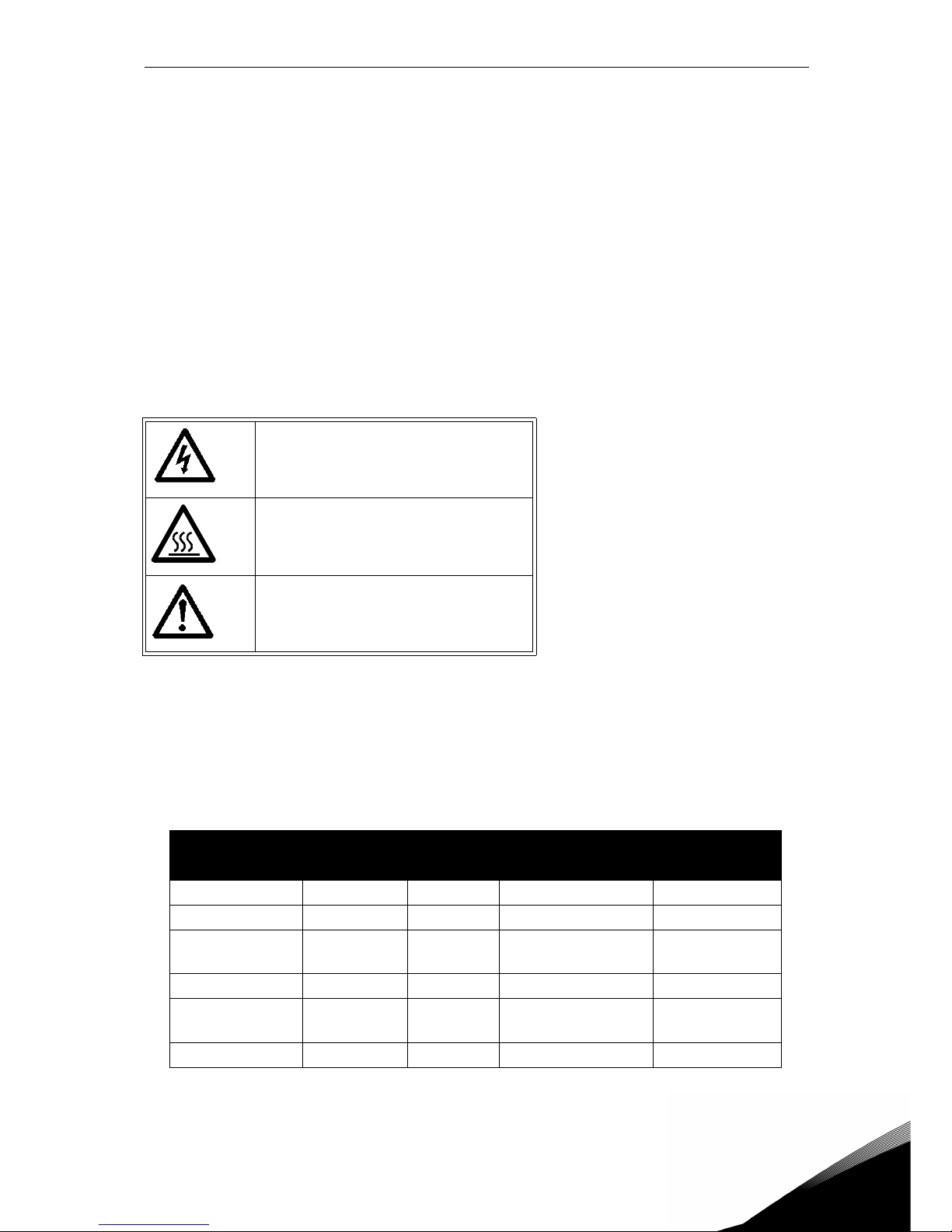
The cautions and warnings are marked as follows:
Table 1. Warning signs.
1.2 Units
The dimensions used in this manual conform to International Metric System units, otherwise
known as SI (Système International d’Unités) units. For the purpose of the equipment's UL certification, some of these dimensions are accompanied by their imperial equivalents.
= DANGEROUS VOLTAGE!
= HOT SURFACE!
= WARNING or CAUTION
Physical
dimension
SI value US value Conversion factor US designation
length 1 mm 0.0394 inch 25.4 inch
Weight 1 kg 2.205 lb 0.4536 pound
Speed
1 min
-1
1 rpm 1
revolution per
minute
Temperature 1 °C (T1) 33.8 °F (T2) T2 = T1 x 9/5 + 32 Fahrenheit
Torque 1 Nm 8.851 lbf in 0.113
pound-force
inches
Power 1 kW 1.341 HP 0.7457 horsepower
Table 2. Unit conversion table.
Page 8
1
vacon • 5 Safety
1.3 Danger
1.4 Hot surface warning
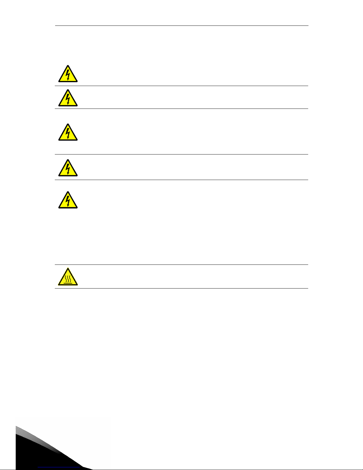
The components of the power unit of VACON® 20 CP drives are live when the
drive is connected to mains potential. Coming into contact with this voltage is
extremely dangerous and may cause death or severe injury.
The motor terminals (U, V, W) are live when VACON
®
20 CP Drive is connected to
the mains, even if the motor is not running.
After disconnecting the AC drive from the mains, wait until the indicators on the
keypad go out (if no keypad is attached, see the indicators on the cover). Wait an
additional 30 seconds before starting any work on the connections of Vacon20
Cold Plate Drive. After expiration of this time, use measuring equipment to absolutely ensure that no
voltage is present.
Always ensure absence of voltage before
starting any electrical work!
The control I/O-terminals are isolated from the mains potential. However, the
relay outputs and other I/O-terminals may have a dangerous control voltage
present even when VACON
®
20 CP Drive is disconnected from the mains.
During a coast stop (see the Application Manual), the motor is still generating
voltage to the drive. Therefore, do not touch the components of the AC drive
before the motor has completely stopped. Wait until the indicators on the keypad
go out (if no keypad is attached, see the indicators on the cover). Wait an additional 30 seconds before starting any work on the drive.
The metal parts of the enclosure may exceed 70°C (158 °F). Do not touch them to
a high risk of being burn.
Page 9
Safety vacon • 6
Service support: find your nearest Vacon service center at www.vacon.com
1
1.5 Warnings
VACON® 20 CP AC drive is meant for fixed installations only.
Only DVC A circuits (Decisive Voltage Class A, according to IEC 61800-5-1) are
allowed to be connected to the control unit. This advice aims to protect both the
drive and the client-application. Vacon is not responsible for direct or consequential damages resulting from unsafe connections of external circuits to the drive.
See paragraph 1.7 for more details.
Do not perform any measurements when the AC drive is connected to the mains.
The touch current of VACON
®
20 CP drives exceeds 3.5mA AC. According to standard EN61800-5-1, a reinforced protective ground connection must be ensured.
See paragraph 1.6.
If the AC drive is used as a part of a machine, the machine manufacturer is
responsible for providing the machine with a supply disconnecting device (EN
60204-1). See paragraph 4.1
Only spare parts supplied by Vacon can be used.
At power-up, power brake or fault reset, the motor will start immediately if the
start signal is active, unless the pulse control for
Start/Stop logic has been selected
.
Furthermore, the I/O functionalities (including start inputs) may change if parameters, applications or software are changed. Disconnect, therefore, the motor if
an unexpected start can cause danger. This is valid only if STO inputs are energized. For prevention on unexpected restart, use appropriate safety relay connected to the STO inputs.
The motor starts automatically after automatic fault reset if the autoreset function is activated. See the Application Manual for more detailed information.
This is valid only if STO inputs are energized. For prevention on unexpected
restart, use appropriate safety relay connected to the STO inputs.
Before performing any measurement on the motor or the motor cable, disconnect the motor cable from the AC drive.
Do not perform any voltage withstand test on any part of VACON
®
20 CP. The
tests shall be performed according to a specific procedure. Ignoring this procedure may damage the product.
Do not touch the components on the circuit boards. Static voltage discharge may
damage the components.
Check that the EMC level of the AC drive corresponds to the requirements of your
supply network.
In a domestic environment, this product may cause radio interference, in which
case supplementary mitigation measures may be required.
Page 10
1
vacon • 7 Safety
1.6 Earthing and earth fault protection
The VACON® 20 CP AC drive must always be earthed with an earthing conductor connected to
the earthing terminal marked with .
Since the touch current exceeds 3.5 mA AC (for the three-phase version), according to
EN61800-5-1, the drive shall have a fixed connection and provision of an additional terminal for
a second protective earthing conductor of the same cross-sectional area as the original protective earthing conductor.
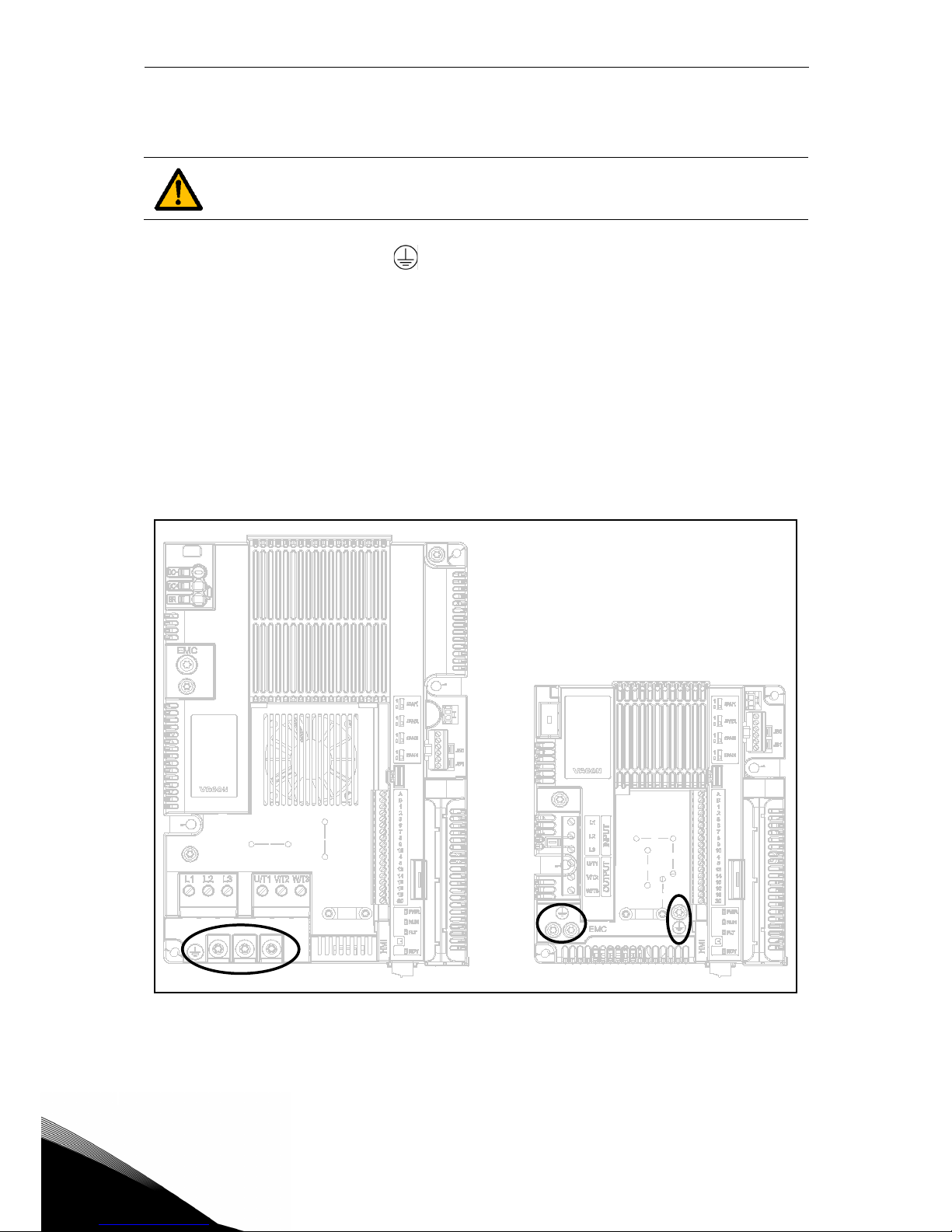
Three screws (for the three-phase version) are provided for: the ORIGINAL protective earthing
conductor, the SECOND protective conductor and the MOTOR protective conductor (the customer can choose the screw for each one). See Figure 1 for the location of the three screws in
the two possible options available.
Figure 1. Protective earthing connections MS2 and MS3, three-phase version.
In VACON® 20 CP, the phase conductor and the corresponding protective earthing conductor
can be of the same cross-sectional area, provided they are made of the same metal (because
the cross-sectional area of the phase conductor is less than 16 mm
2
).
CAUTION!
Page 11
Safety vacon • 8
Service support: find your nearest Vacon service center at www.vacon.com
1
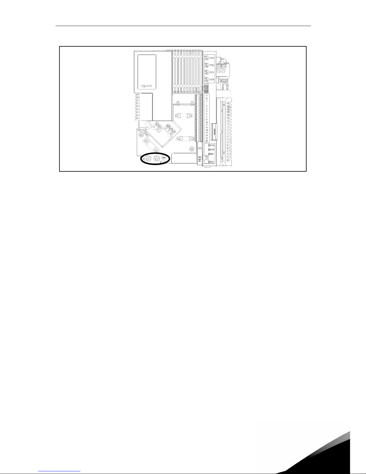
Figure 2.Protective earthing connections MS2, single-phase version.
The cross-sectional area of every protective earthing conductor which does not form a part of
the supply cable or cable enclosure shall, in any case, be not less than:
•2.5 mm
2
if mechanical protection is provided or
•4 mm
2
if mechanical protection is not provided. For cord-connected equipment, provisions shall be made so that the protective earthing conductor in the cord shall, in the
case of failure of the strain-relief mechanism, be the last conductor to be interrupted.
However, always follow the local regulations for the minimum size of the protective earthing
conductor.
NOTE: Due to the high capacitive currents present in the AC drive, fault current protective
switches may not function properly.
Page 12
1
vacon • 9 Safety
1.7 Insulation system
A distinction has to be made for the following three groups of terminals, according to the insulation system of VACON
®
20 CP:
• Mains and motor connections (L1, L2, L3, U, V, W) or (L, N, U, V, W)
• Relays (R01, R02)
(**)
• Control terminals (I/Os, RS485, STO)
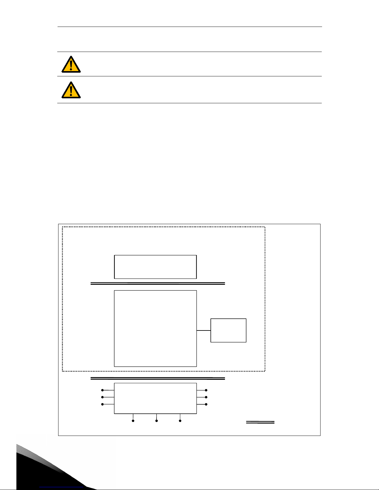
The Control terminals (I/Os, RS485, STO) are isolated from the Mains (the insulation is reinforced, according to IEC 61800-5-1) and the GND terminals are referred to PE.
This is important when you need to connect other circuits to the drive and test the complete
assembly. Should you have any doubts or questions, please contact your local Vacon distributor.
Figure 3. Insulation system (three-phase version).
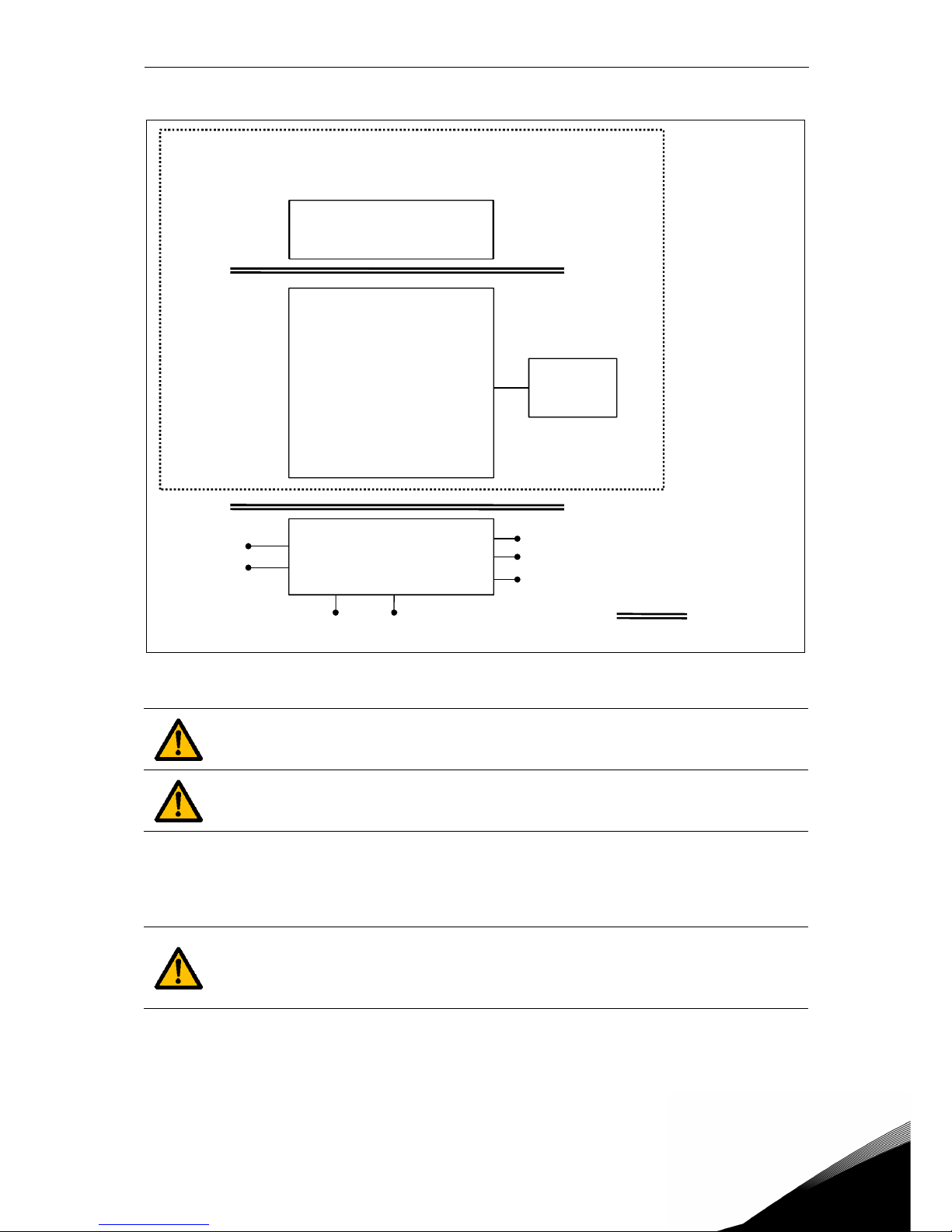
Please, consider carefully the insulation system depicted in Figure 2, before connecting any circuit to the unit.
The control unit of VACON
®
20 CP fulfils the insulation requirements of the standard IEC 61800-5-1 regarding DVC A circuits and also the strongest insulation
requirements of IEC 60950-1 regarding SELV circuits.
POWER UNIT
L1
L2
L3
U
V
W
R01 __
R02 __
10Vref __
Analog Inputs __
Digital Inputs__
Analog Output __
24V __
RS485 __
STO __
Keypad
CONTROL UNIT
Reinforced
Mains
DVC A
DVC A or Mains
(**)
DC-
(*)
DC+/R+ R-
Page 13
Safety vacon • 10
Service support: find your nearest Vacon service center at www.vacon.com
1
Figure 4. Insulation system (single-phase version).
1.8 Compatibility with RCDs
(*)
Only for MS3.
(**)
The relays may be used also with DVC A circuits. This is possible only if both
relays are used for DVC A circuitry: to mix Mains and DVC A is not allowed.
This product can cause a d.c. current in the protective earthing conductor. Where
a residual current-operated protective (RCD) or monitoring (RCM) device is
used for protection in case of direct or indirect contact, only an RCD or RCM of
Type B is allowed on the supply side of this product.
POWER UNIT
L
N
U
V
W
R01 __
R02 __
10Vref __
Analog Inputs __
Digital Inputs__
Analog Output __
24V __
RS485 __
Keypad
CONTROL UNIT
Reinforced
Mains
DVC A
DVC A or Mains
(**)
DC- DC+
Page 14

1
vacon • 11 Safety
1.9 Cooling System
VACON® 20 CP is available as a cold-plate solution. Customers have to enclose it in their own
housing and provide a suitable heatsink. However under maximum operating conditions the
unit should not exceed the following temperatures:
• Temperature around the polymeric enclosure (of VACON
®
20 CP): max. 70 °C (158 °F)
• Temperature at the cooling-plate (of VACON
®
20 CP): max. 85 °C (185 °F)
Please, contact your local Vacon distributor if you need further details or support to dimension
the cooling system in your final application.
NOTE: Up to 1.5 kW (Voltage range 380-480V) and 0.75 kW (Voltage range 208-240V) the drive
is not equipped with external cooling fan.
Page 15
Safety vacon • 12
Service support: find your nearest Vacon service center at www.vacon.com
1
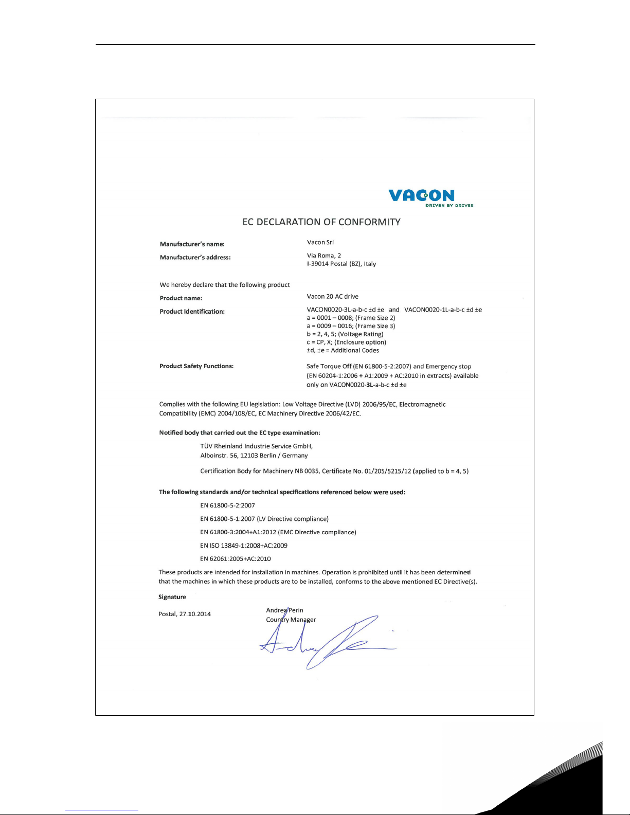
1.10 Declaration of conformity
Figure 5. Declaration of conformity.
Page 16
1
vacon • 13 Safety
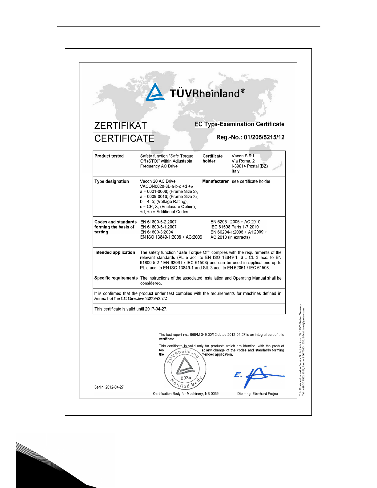
Figure 6. STO certificate.
Page 17

Safety vacon • 14
Service support: find your nearest Vacon service center at www.vacon.com
1
NOTE! You can download the English and French product manuals with applicable safety,
warning and caution information from www.vacon.com/downloads.
REMARQUE Vous pouvez télécharger les versions anglaise et française des manuels produit
contenant l’ensemble des informations de sécurité, avertissements et mises en garde applicables sur le site www.vacon.com/downloads.
Page 18

1
vacon • 15 Safety
Page 19
Receipt of delivery vacon • 16
Service support: find your nearest Vacon service center at www.vacon.com
2
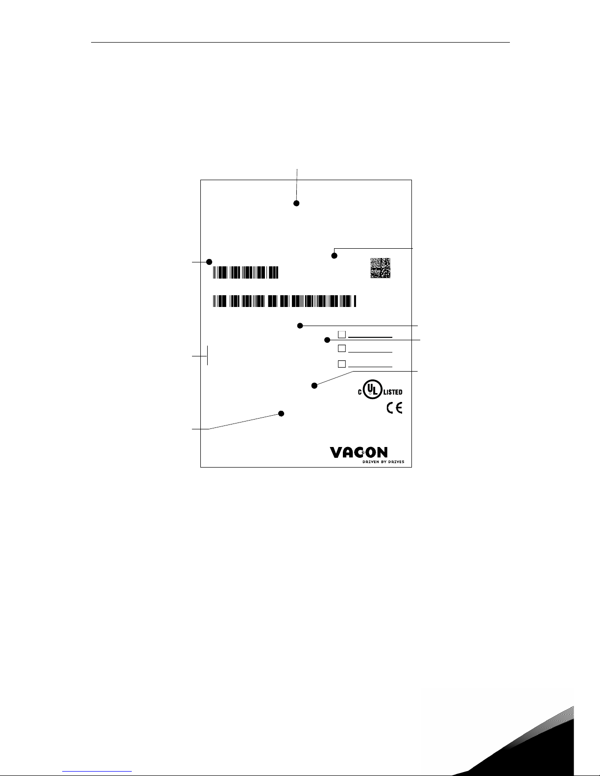
2. RECEIPT OF DELIVERY
Check correctness of delivery by comparing your order data to the drive information found on
the package label. If the delivery does not correspond to your order, contact your supplier immediately. See paragraph 2.4.
Figure 7. Vacon package label
Marks:
3234500378
Cust. Ord. No:
Application:
FW0065V008
Firmware:
EMC level:
380-480 V
IP00
6 A
Rated current:
122245
B.ID:
M100112345
S/N:
70SCO000293-BM1X
Code:
VACON0020-3L-0006-4-CP
Type:
AC DRIVE
Rated voltage:
Protection:
C2
Vacon type code
Rated
current
Supply
voltage
Application
code
IP class
EMC level
Serial number
CUSTOMER NAME
Customer’s
order number
Batch ID
Page 20

vacon • 17 Receipt of delivery
2
2.1 Type designation code
Vacon® type designation code is formed of a nine-segment code and optional +codes. Each
segment of the type designation code uniquely corresponds to the product and options you
have ordered. The format of the code is as follows:
VACON0020-3L-0009-4-CP +xxxx +yyyy
+xxxx +yyyy
Additional codes.
Examples of additional codes:
+DBIR
Dynamic Brake Internal Resistance (optional)
Page 21
Receipt of delivery vacon • 18
Service support: find your nearest Vacon service center at www.vacon.com
2
2.2 Order codes
The order codes for Vacon 20 Cold Plate drive family are shown in the following table:
For all technical details, see chapter 7.
Frame size Order code Description
Supply voltage 3AC 208-240V
MS2
VACON0020-3L-0004-2-CP 0.75 kW - 1.0 HP drive
VACON0020-3L-0005-2-CP 1.1 kW - 1.5 HP drive
VACON0020-3L-0007-2-CP 1.5 kW - 2.0 HP drive
MS3
VACON0020-3L-0011-2-CP 2.2 kW - 3.0 HP drive
VACON0020-3L-0012-2-CP 3.0 kW - 4.0 HP drive
VACON0020-3L-0017-2-CP 4.0 kW - 5.0 HP drive
Supply voltage 1AC 208-240V
MS2
VACON0020-1L-0004-2-CP 0.75 kW - 1.0 HP drive
VACON0020-1L-0005-2-CP 1.1 kW - 1.5 HP drive
VACON0020-1L-0007-2-CP 1.5 kW - 2.0 HP drive
Supply voltage 3AC 380-480V
MS2
VACON0020-3L-0003-4-CP 0.75 kW - 1.0 HP drive
VACON0020-3L-0004-4-CP 1.1 kW - 1.5 HP drive
VACON0020-3L-0005-4-CP 1.5 kW - 2.0 HP drive
VACON0020-3L-0006-4-CP 2.2 kW - 3.0 HP drive
VACON0020-3L-0008-4-CP 3.0 kW - 4.0 HP drive
MS3
VACON0020-3L-0009-4-CP 4.0 kW - 5.0 HP drive
VACON0020-3L-0012-4-CP 5.5 kW - 7.5 HP drive
VACON0020-3L-0016-4-CP 7.5 kW - 10.0 HP drive
Table 3. Order codes of Vacon 20 Cold Plate.
Page 22
vacon • 19 Receipt of delivery
2
2.3 Unpacking and lifting the AC drive
The weights of the AC drives vary according to frame size. Note the weights of each individual
frame size in Table 4 below.
Table 4. Frame weights.
VACON® 20 Cold Plate drives have undergone scrupulous tests and quality checks at the factory before they are delivered to the customer. However, after unpacking the product, check
that no signs of transport damage are to be found on the product and that the delivery is complete.
Should the drive have been damaged during shipping, please contact the cargo insurance company or the carrier in the first instance.
2.4 Accessories
After lifting the converter out, check that the delivery is complete and the following accessories
are included in the plastic bag:
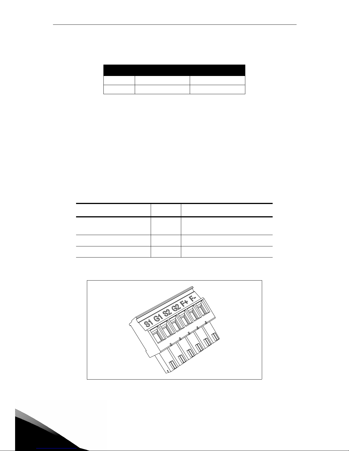
Figure 8. STO connector.
Frame Weight [kg] Weight [lb]
MS2 2 4.4
MS3 3 6.6
Item Quantity Purpose
STO terminal connector
*
*. Included only in the MS2 three-phase version and MS3.
1
Six pin black connector (see
Figure 8) to use STO function
M3.5 x 8 TapTite screw 4 Screws for control cable clamps
M1-3 Cable clamp 2 Clamping control cables
Page 23
Receipt of delivery vacon • 20
Service support: find your nearest Vacon service center at www.vacon.com
2
2.4.1 Disposal
When the device reaches the end of its operating life do not
dispose of it as a part of standard household garbage. Main
components of the product can be recycled, but some need to
be fragmented to separate different types of materials and
components that need to be treated as special waste from
electrical and electronic components. To ensure
environmentally sound and safe recycling treatment, the
product can be taken to appropriate recycling center or
returned to the manufacturer.
Observe local and other applicable laws as they may mandate
special treatment for specific components or special
treatment may be ecologically sensible.
13064.emf
Page 24

vacon • 21 Receipt of delivery
2
Page 25
Mounting vacon • 22
Service support: find your nearest Vacon service center at www.vacon.com
3
3. MOUNTING
The AC drive can be mounted on the wall or on the back plane of a cubicle. Ensure that the
mounting plane is relatively even. Both frame sizes can be mounted in any position (IP20 rating
is preserved only if mounted as in the following pictures). The drive shall be fixed with two
screws (or bolts, depending on the unit size).
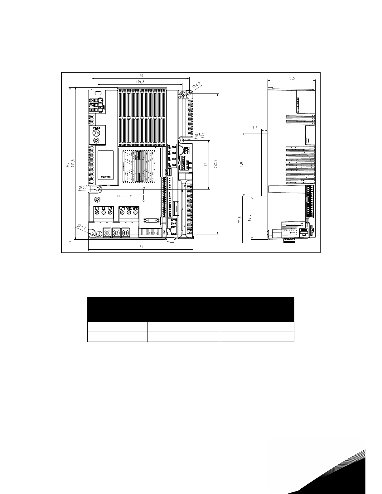
3.1 Dimensions
3.1.1 Frame MS2 three-phase version
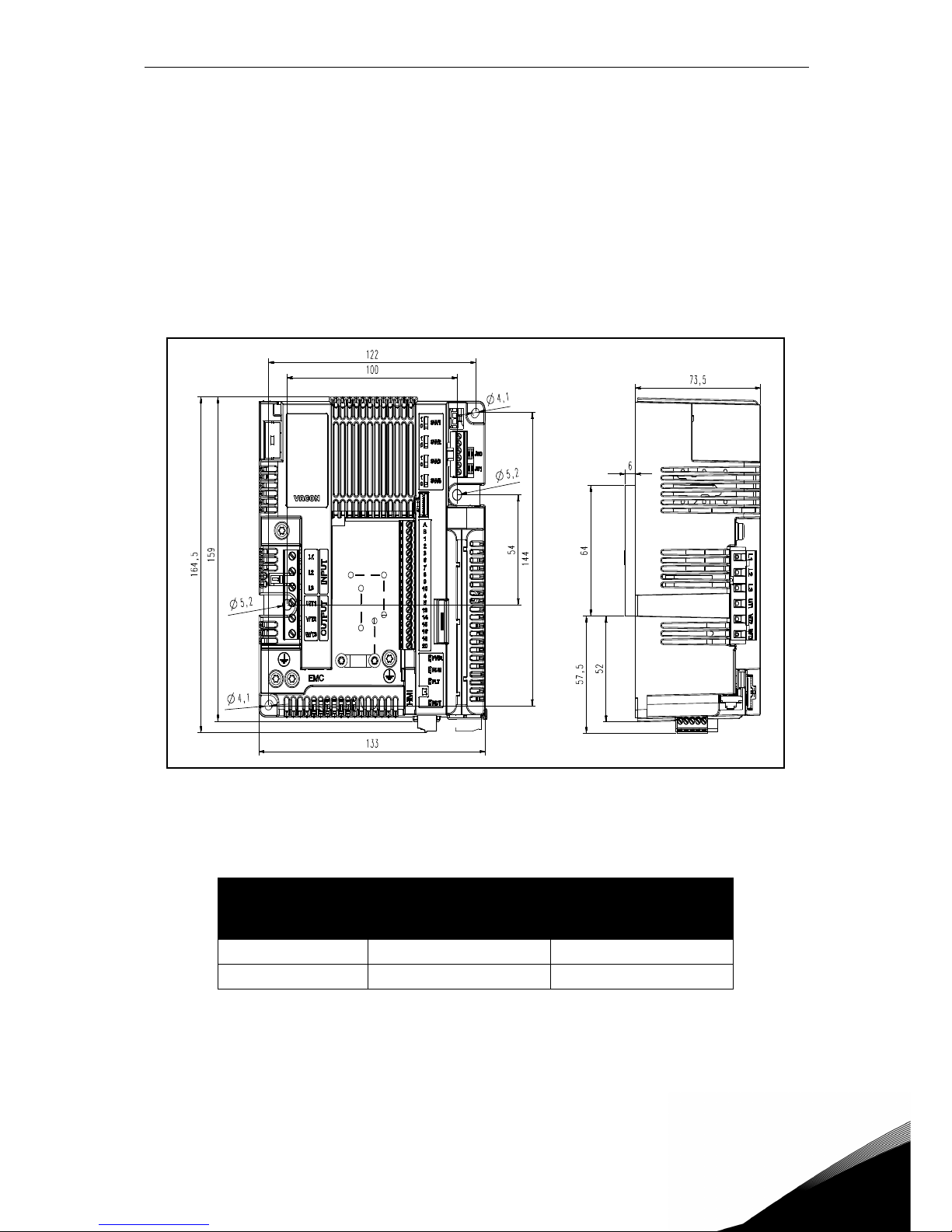
Figure 9. VACON® 20 Cold Plate, MS2 three-phase version.
Frame
Dimensions W x H x D
[mm] [in]
MS2 133.0 x 164.5 x 73.5 5.24 x 6.48 x 2.89
MS2 with plate 133.0 x 164.5 x 79.5 5.24 x 6.48 x 3.13
Page 26
3
vacon • 23 Mounting
3.1.2 Frame MS2 single-phase version
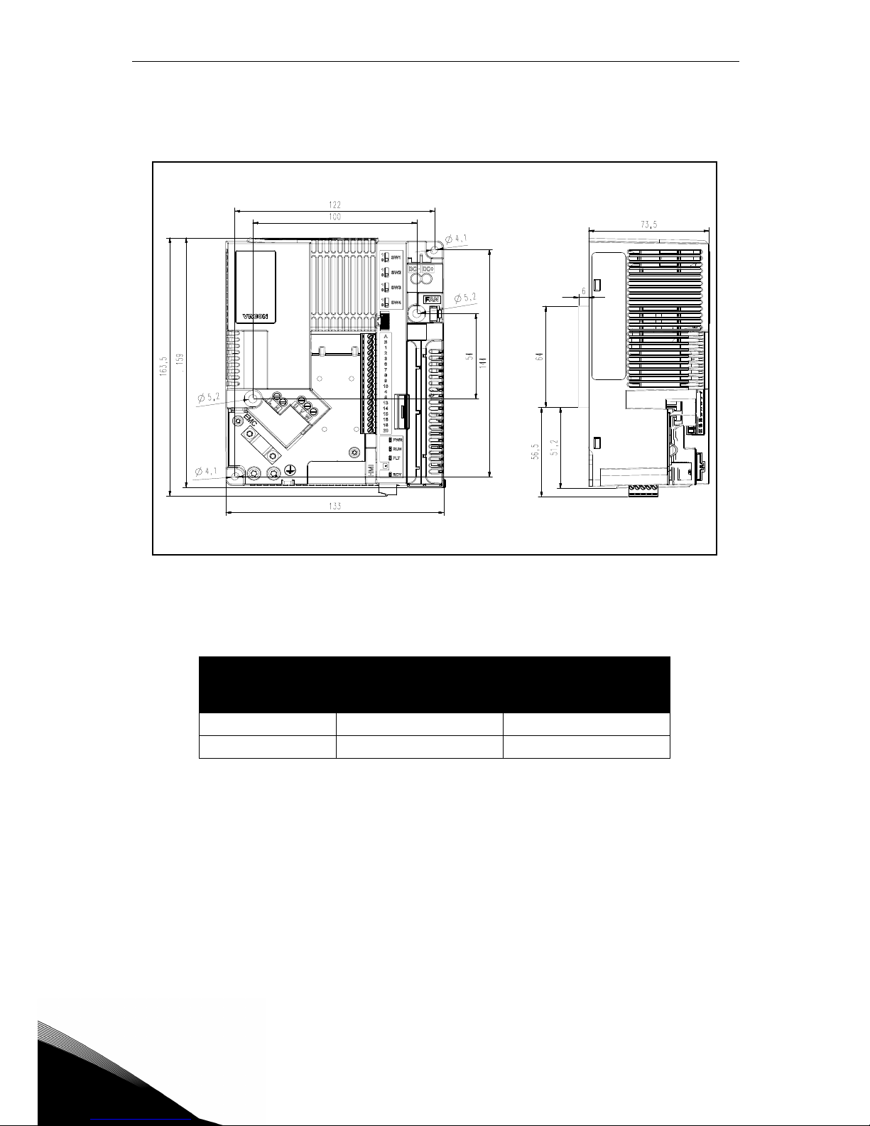
Figure 10. VACON® 20 Cold Plate, MS2 single-phase version.
Frame
Dimensions W x H x D
[mm] [in]
MS2 133.0 x 163.5 x 73.5 5.23 x 6.43 x 2.89
MS2 with plate 133.0 x 163.5 x 79.5 5.23 x 6.43 x 3.13
Page 27
Mounting vacon • 24
Service support: find your nearest Vacon service center at www.vacon.com
3
3.1.3 Frame MS3
Figure 11. VACON® 20 Cold Plate, MS3.
Frame
Dimensions W x H x D
[mm] [in]
MS3 161.0 x 246.0 x 73.5 6.34 x 9.69 x 2.89
MS3 with plate 161.0 x 246.0 x 83.0 6.34 x 9.69 x 3.27
Page 28
3
vacon • 25 Mounting
3.2 Cooling
The AC drive produces heat in operation due to the energy dissipation of the electronic components (rectifier and IGBT) and is cooled by a heatsink via the cold plate of the frequency converter. The capacity to dissipate this heat mainly depends on the size of the heatsink surface,
the environment temperature and the heat transmission resistance. An increase of the heat
transmission rate can only be realized to a certain extent by increasing the surface of the heatsink. An additional increase of the heat dissipation by increasing the heatsink is not possible.
The frequency converter should be mounted with the cold plate on a heatsink with lowest thermal resistance possible.
3.3 Environment temperature
The drive environment temperature shall not exceed 70 °C (158 °F) for the drive installed location. The aluminium panel of the back of the drive is called “cold plate”. The cold plate should
never exceed 85 °C (185 °F).
3.4 Heatsink assembly instructions
The VACON® 20 CP frequency converters are designed for installation on surfaces which comply with the specifications listed in this paragraph.
The heatsink surface that is in contact with the frequency converter cold plate must be free
from dirt and particles. The mating surface flatness shall not exceed 50μm (DIN EN ISO 1101)
across the entire mating surface, and the roughness less than 6.3 μm (DIN EN ISO 4287). The
maximum peak-valley height of the surface shall not exceed 10 μm (DIN EN ISO 4287).
Apply a thermal compound between the heatsink and the AC drive cooling mating surface. The
thermal paste assists the drive heat dissipation. Vacon recommends the thermal compounds
listed in the following table:
Vacon recommends screen printing for applying the thermal paste. In certain cases an application by hard rubber roller might be applicable. After mounting the AC drive to the heatsink
panel, wipe away any excess compound from around the plate.
The drive may be damaged if the temperature of the cooling plate exceeds specified tolerance level. Excessive heat can also shorten the performance life of the
various AC drive components.
Manufacturer Type Model
Recommended
spread amount
Wacker Chemie
Silicon paste for heat
dissipation
P 12
100 μm
Apply the coating
evenly across the
surface
Fischer Elektronik WLPF
Silicon paste for heat
dissipation
WLPF
Table 5. Recommended cold plate thermal compound.
Page 29
Mounting vacon • 26
Service support: find your nearest Vacon service center at www.vacon.com
3
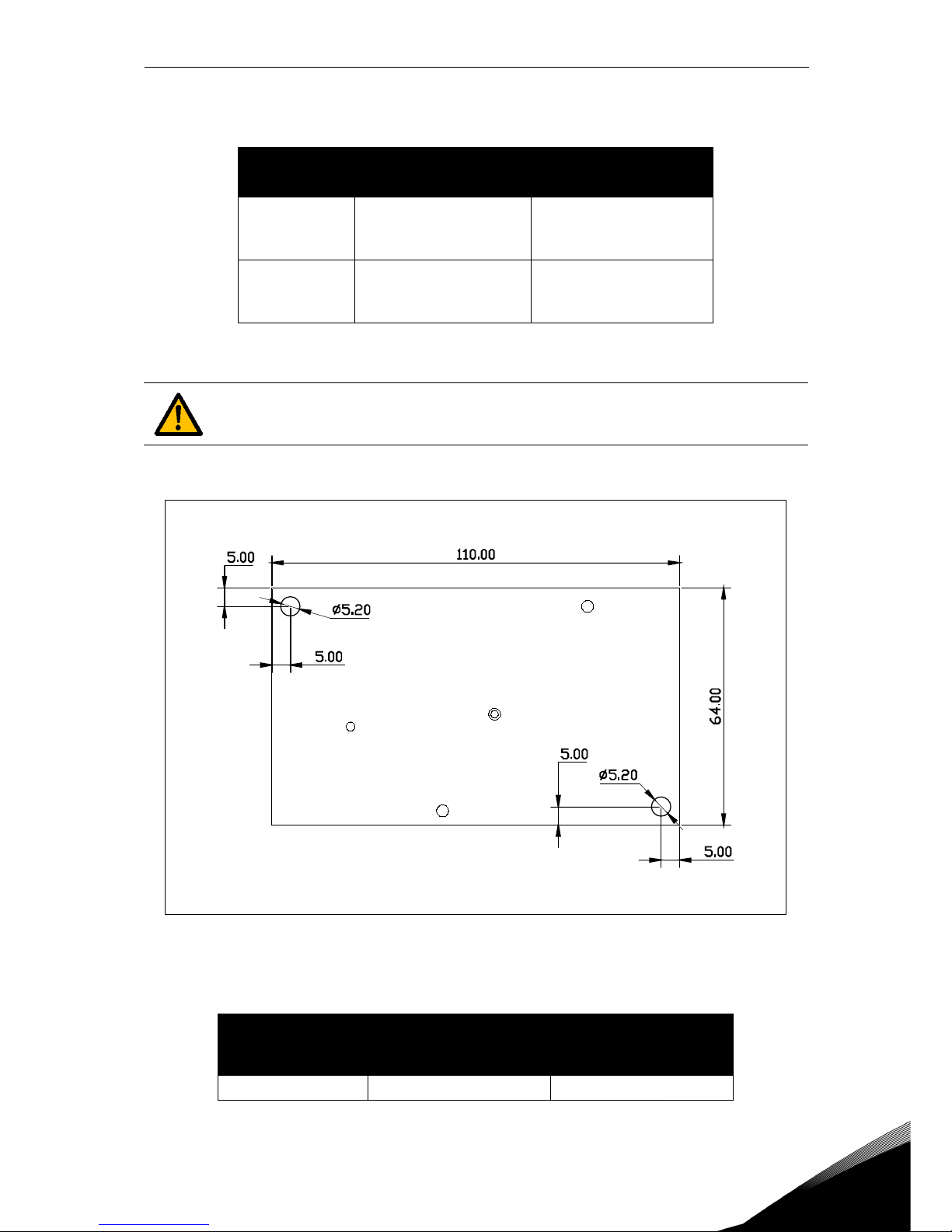
Place the VACON® 20 CP on the appropriate heatsink area and tighten the screws as listed in
the following table:
Figure 12. Heatsink plate for MS2 (upper view).The thickness of the plate is 6.0 mm (0.24
in).
Frame size Screw size
Tightening torque N•m
(lb•in)
MS2
M5 (according to DIN
7985 - 8.8
(with washer))
2.0 to 2.5 Nm
(17.70 to 22.13 lbf•in)
MS3
M5 (according to DIN
7985 - 8.8
(with washer))
2.0 to 2.5 Nm
(17.70 to 22.13 lbf•in)
Table 6. Screw size and tightening torque.
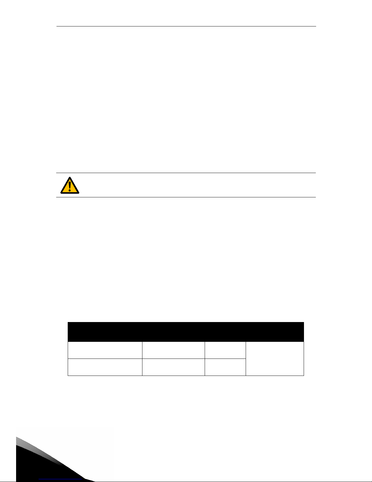
Tighten all screws according to specified torques. Failure to do so, may inhibit
drive cooling and cause possible damage to the drive.
Frame
Dimensions W x H x D
[mm] [in]
MS2 64.0 x 110.0 x 6.0 2.52 x 4.33 x 0.24
Page 30
3
vacon • 27 Mounting
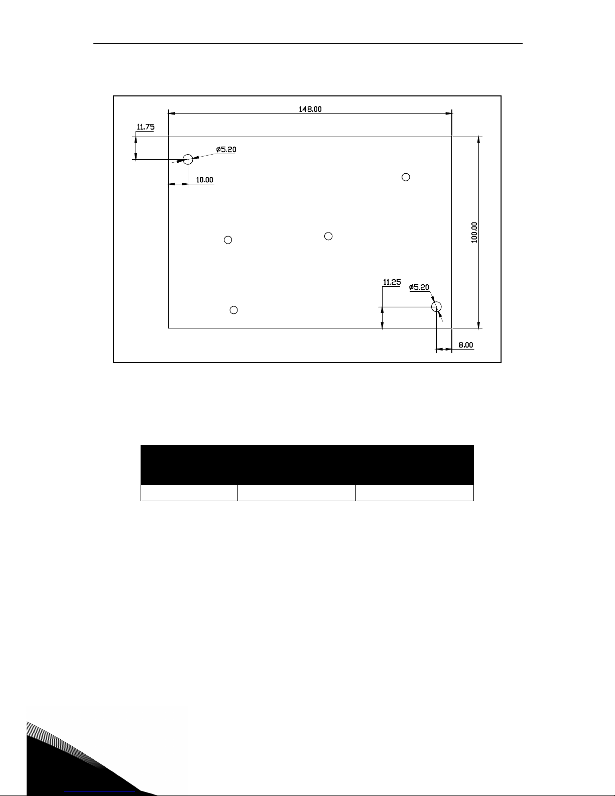
Figure 13. Heatsink plate for MS3 (upper view).The thickness of the plate is 9.5 mm (0.37
in).
Frame
Dimensions W x H x D
[mm] [in]
MS3 100.0 x 148.0 x 9.5 3.94 x 5.83 x 0.37
Page 31
Mounting vacon • 28
Service support: find your nearest Vacon service center at www.vacon.com
3
3.5 Installation spacing
Enough free space shall be left around the AC drive to ensure sufficient air circulation and
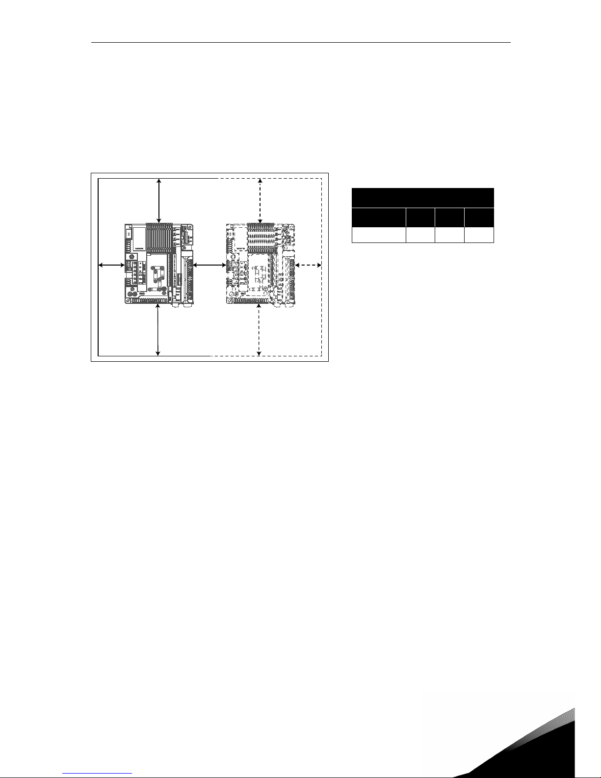
cooling. Different acts of maintenance may also require a certain amount of free space.
The minimum clearances given in Table 7 must be respected. It is also important to ensure
that the temperature of the cooling air does not exceed the maximum environment temperature of the converter.
Contact our factory for more information on required clearances in different installations.
Table 7. Min. clearances around AC
drive.
A = Clearance left and right from the drive
B = Clearance above the drive
C = Clearance underneath the AC drive
Figure 14. Installation space.
Min clearance mm
Type A B C
All types 303030
B
AACA
Page 32
3
vacon • 29 Mounting
3.6 Power loss thermal characteristics
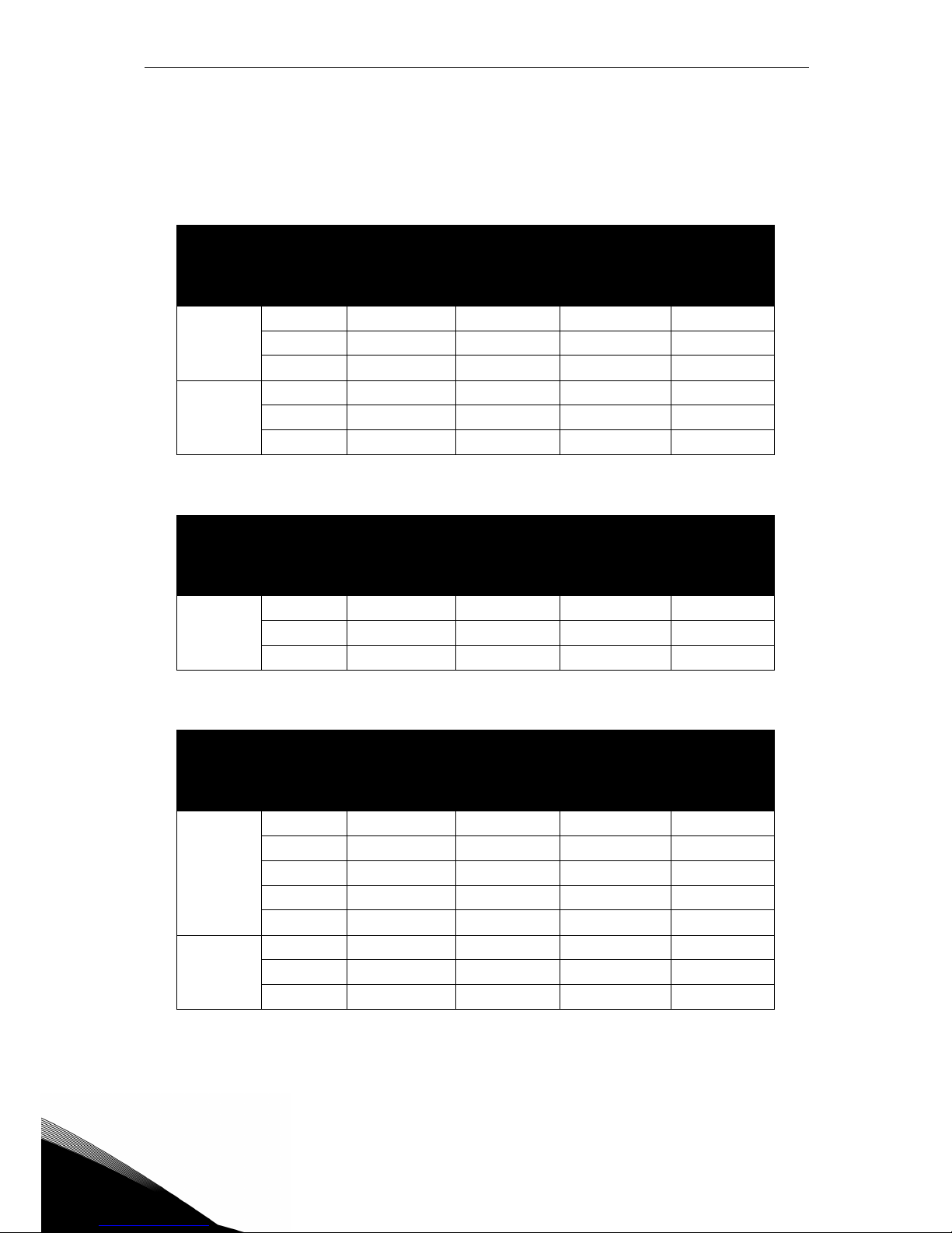
In the table below are the thermal characteristics of VACON® 20 CP AC drive at nominal output
current. The power loss in stand-by conditions is 12 W for all sizes (supply voltage 24 V, 100
mA).
Mains voltage 3AC 208-240V, 50/60 Hz
Frame
Converter
Type
Rated output
current [A]
Cold plate
loss [W]
Internal loss
[W]
Total loss
[W]
MS2
0004 3.7 27 18 45
0005 4.8 37 21 58
0007 7.0 58 30 88
MS3
0011 11.0 85 28 113
0012 12.5 101 37 138
0017 17.5 146 50 196
Table 8. Drive power loss at rated conditions, voltage range 3AC 208-240V.
Mains voltage 1AC 208-240V, 50/60 Hz
Frame
Converter
Type
Rated output
current [A]
Cold plate
loss [W]
Internal loss
[W]
Total loss
[W]
MS2
0004 3.7 31 22 53
0005 4.8 37 24 61
0007 7.0 59 31 90
Table 9. Drive power loss at rated conditions, voltage range 1AC 208-240V.
Mains voltage 3AC 380-480V, 50/60 Hz
Frame
Converter
Type
Rated output
current [A]
Cold plate
loss [W]
Internal loss
[W]
Total loss
[W]
MS2
0003 2.4 23 16 39
0004 3.3 31 18 49
0005 4.3 43 21 64
0006 5.6 58 25 83
0008 7.6 84 33 117
MS3
0009 9.0 86 31 117
0012 12.0 120 37 157
0016 16.0 171 48 219
Table 10. Drive power loss at rated conditions, voltage range 3AC 380-480V.
Page 33
Mounting vacon • 30
Service support: find your nearest Vacon service center at www.vacon.com
3
3.7 Dimensioning an external heatsink
This paragraph describes a useful procedure to select a suitable heatsink for VACON® 20 CP
drives.
The heatsinks are devices that enhance heat dissipation from a hot surface, usually the case
of a heat generating component, to a cooler ambient, usually air. For the following discussion,
air is assumed to be the cooling fluid. The primary purpose of a heatsink is to maintain the device temperature below the maximum allowable specified by the device manufacturers. Before
discussing the heatsink selection process, it’s necessary to define common terms, notations
and definitions and establish the concept of a thermal circuit.
Notations and definitions of the terms are as follows:
The purpose of this paragraph is to select an external heatsink by calculating its thermal resistance.
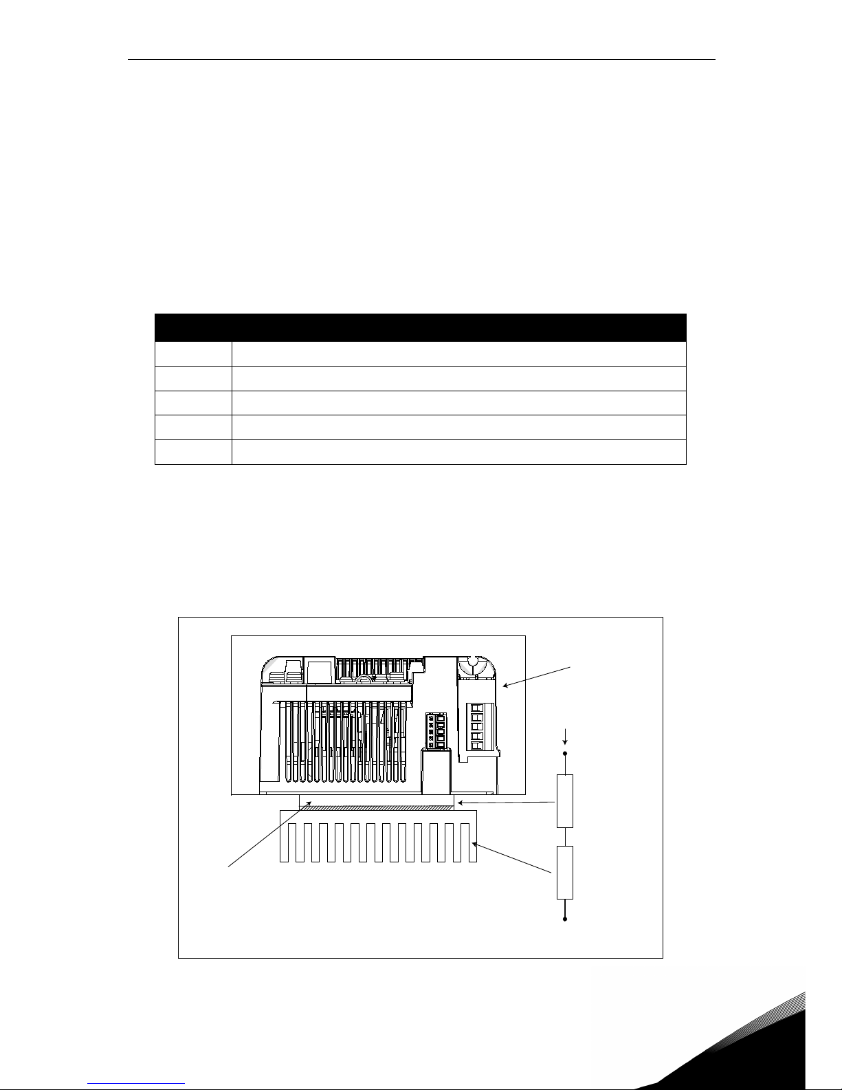
The heat transfer principle from the cold plate to the heatsink ambient air is shown in Figure
15.
Figure 15.Thermal equivalent circuit.
Symbol Description
CP
loss
Cold plate loss: see Table 8, Table 9 or Table 10 expressed in W
T
CPmax
Maximum cold plate temperature expressed in °K (358 °K = 85°C)
T
amb
heatsink ambient temperature expressed in °K(°K = °C + 273)
R
CP
Equivalent thermal resistance [K/W] of the cold plate.
R
HSmax
Thermal resistance of the heatsink [K/W]
Table 11. Terms and definitions for the thermal model.
CP
loss
T
amb
R
CP
R
HS
T
CP
T
CP
T
amb
T
Enclosure
Page 34
3
vacon • 31 Mounting
The formula to calculate the maximum thermal resistance of the heatsink is as follows:
For a given ambient temperature T
amb
the cold plate temperature T
CPmax
must not exceed the
maximum allowable value (85°C). As the R
CP
is essentially fixed, this condition must be satis-
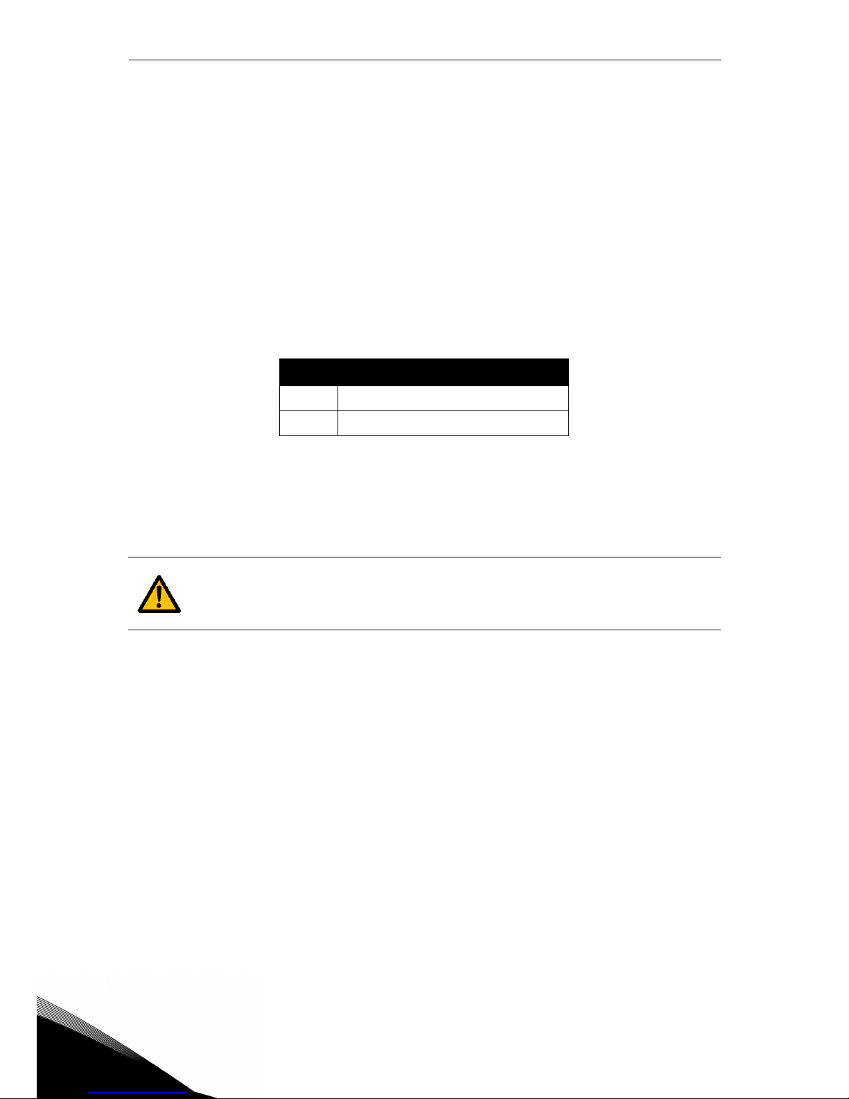
fied with a proper heatsink selection. The table below shows the typical values for R
CP
for VA-
CON
®
20 CP:
Select a heatsink with a smaller thermal resistance than R
HSmax
. The heatsink dimensions
should be closed to the cold plate dimensions.
Note: remember that the heatsink cooling capacity can be reduced over time due to dirt.
In order to choose an heatsink from a catalogue please consider that usually the reported heat
resistances are measured under free convection conditions. In this case the heatsink has to be
oversized with respect to the cold plate dimensions, otherwise an additional fan must be used
to reduce the heatsink resistance and its dimensions. Most heatsink manufacturers give correction factors according to various air flow speeds.
The designing factors which influence the thermal performances of an heatsink are as follows:
• Spreading resistance: Spreading resistance occurs when thermal energy is transferred
from a small area to a larger area in a substance with finite thermal conductivity. In a heatsink, this means that heat does not distribute uniformly through the heatsink base. The
spreading resistance phenomenon is shown by how the heat travels from the heat source
location and causes a large temperature gradient between the heat source and the edges
of the heatsink. This means that some fins are at a lower temperature than if the heat
source were uniform across the base of the heatsink. This non uniformity increases the
heatsink's effective thermal resistance.
• Heatsink manufacturer dimensioning data: the heatsink thermal resistance given in a
catalogue is measured on a temperature sink to ambient differential (ΔT) and since Rhs
under free convection depends on ΔT with the power law Rth ~ ΔT
-0,25
(with laminar flow),
Frame R
CP
MS2
R
CP
=0.091 K/W
MS3
R
CP
= 0,055 K/W
Table 12. Typical values for the equivalent thermal resistances of the cold plate.
If the heatsink height and width are much larger than the drive cold plate dimensions, or if multiple drives are installed on one heatsink, it may be necessary to
apply correction factors to the thermal resistance value given in the heatsink
specification. Contact the heatsink manufacturer.
R
HSmax
T
CPmaxTamb
–
CP
loss
------------------------------------- RCP–=
Page 35
Mounting vacon • 32
Service support: find your nearest Vacon service center at www.vacon.com
3
a correction factor must be considered when the operating ΔT is different from what used
by the heatsink manufacturer in the measurement.
• Surface finishing: the heatsink dissipation depends on the type of surface finishing of
heatsink itself (anodized/black surfaces dissipate differently from polished surfaces).
• Heatsink attachment/orientation: heatsink attachment/orientation plays a significant
role under natural convection. It is recommended that the heatsink be installed to orient
the fins in a direction that will not block air movement under natural convection. Based
practical experience, if the heatsink is oriented in a wrong way, the thermal performance
will be approximately 25% worse under natural convection condition.
Note: to study the heat transfer in other cooling media of different geometry (e.g. cooling
plate without fins), please contact your local Vacon supplier to receive support in dimensioning method.
Taking account of the above, we recommend that the calculated R
HS
is multiplied by 0.7 to obtain a resistance value with a reasonable safety margin in order
to ensure tripless drive operation.
Page 36

3
vacon • 33 Mounting
Page 37
Power cabling vacon • 34
Service support: find your nearest Vacon service center at www.vacon.com
4
4. POWER CABLING
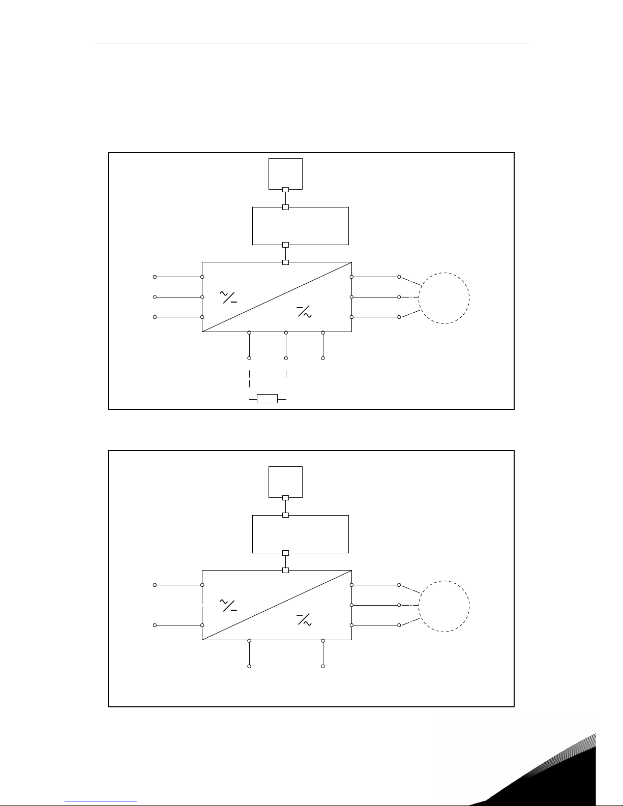
The mains cables are connected to terminals L1, L2 and L3 (three-phase versions) and the motor cables to terminals marked with U, V and W. See principal connection diagram in Figure 16.
See also Table 13 for the cable recommendations for different EMC levels.
Figure 16. Principal connection diagram (three-phase version).
* only MS3.
Figure 17. Principal connection diagram (single-phase version)
U/T1
V/T2
W/T3
M
L1
L2
L3
DC+/R+
R-
DC-
(*)
Keypad
Control
Power unit
U/T1
V/T2
W/T3
M
L
N
Keypad
Control
Power unit
Page 38
4
vacon • 35 Power cabling
Use cables with heat resistance in accordance with the application requirements. The cables
and the fuses must be dimensioned according to the AC drive nominal OUTPUT current which
you can find on the rating plate.
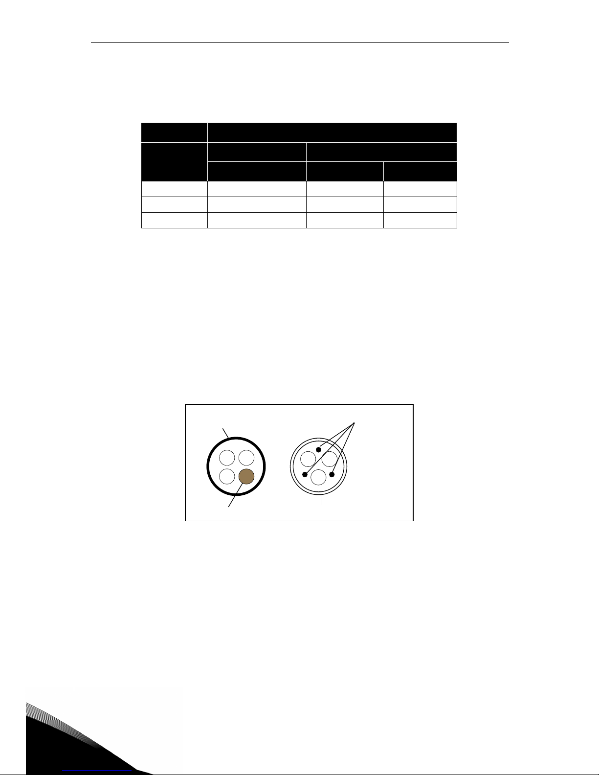
1 = Power cable intended for fixed installation and the specific mains voltage. Shielded
cable not required. (MCMK or similar recommended).
2 = Symmetrical power cable equipped with concentric protection wire and intended for the
specific mains voltage. (MCMK or similar recommended). See Figure 18.
3 = Symmetrical power cable equipped with compact low-impedance shield and intended
for the specific mains voltage. [MCCMK, EMCMK or similar recommended; Recommended cable transfer impedance (1...30MHz) max. 100mohm/m]. See Figure 18.
*360º earthing of the shield with cable glands in motor end needed for EMC category C1
and C2.
4 = Screened cable equipped with compact low-impedance shield (JAMAK, SAB/ÖZCuY-O
or similar).
Figure 18. Example with three-phase cable.
NOTE: The EMC requirements are fulfilled at factory defaults of switching frequencies (all
frames).
NOTE: If safety switch is connected the EMC protection shall be continuous over the whole cable installation.
EMC levels
Cable type
1st environment 2nd environment
Category C1 and C2 Category C3 Category C4
Mains cable 1 1 1
Motor cable 3* 2 2
Control cable 4 4 4
Table 13: Cable types required to meet standards.
Shield
PE conduc tors
Shield
PE conductor
Page 39
Power cabling vacon • 36
Service support: find your nearest Vacon service center at www.vacon.com
4
4.1 Circuit breaker
Please disconnect the drive via an external circuit breaker. You have to provide a switching device between supply and main connection terminals.
When connecting the input terminals to the power supply using a circuit breaker, observe that
this is of type B or type C and ensure is has a capacity of 1.5 to 2 times the inverter’s rated
current (see Table 30).
NOTE: circuit breaker is not allowed in installations where C-UL is required. Only fuses are
recommended.
4.2 UL standards on cabling
To meet the UL (Underwriters Laboratories) regulations, use a UL-approved copper cable with
a minimum heat-resistance of 75°C. Use Class 1 wire only.
The units are suitable for use on a circuit capable of delivering no more than 50,000 rms symmetrical amperes, 600V AC maximum, when protected by T or J class fuses.
Integral solid state short circuit protection does not provide branch circuit protection. Branch circuit protection must be provided in accordance with the
National Electrical Code and any additional local codes.
Page 40
4
vacon • 37 Power cabling
4.3 Description of the terminals
The following pictures describe the power terminals and the typical connections in Vacon® 20
CP drives.
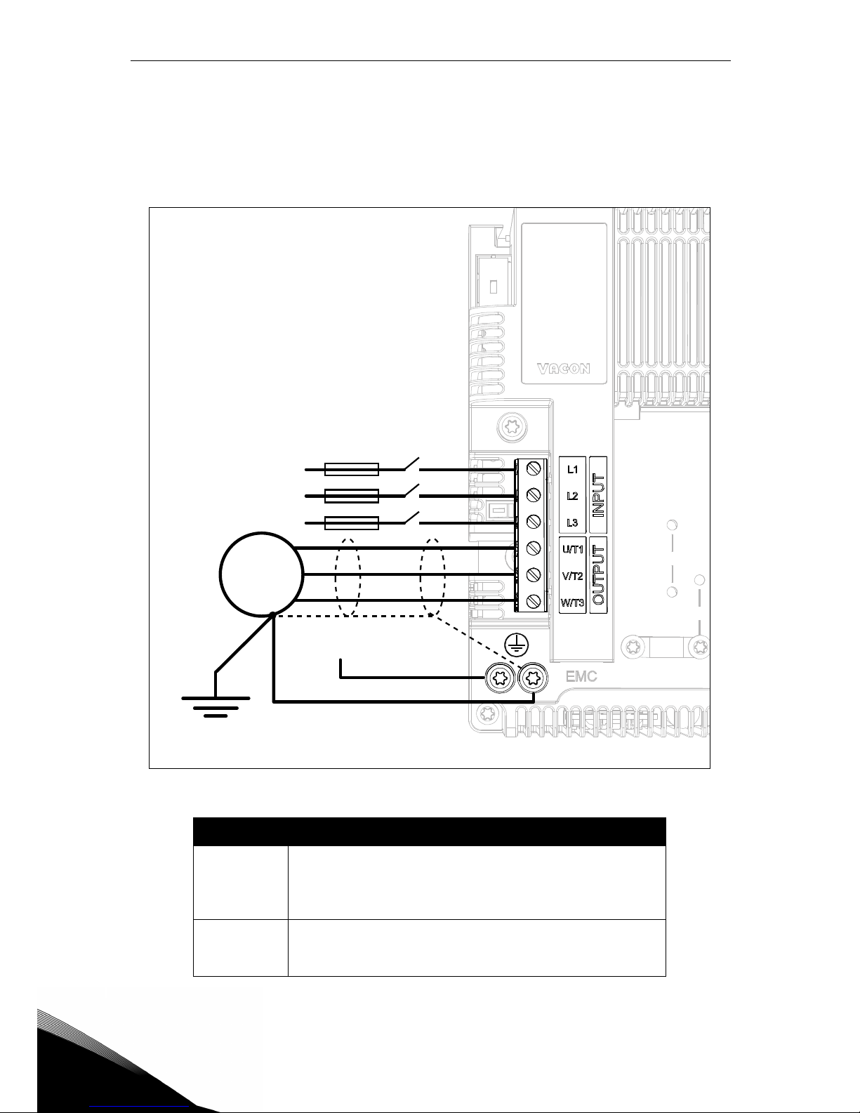
4.3.1 MS2 three-phase version power connections
Figure 19. Power connections, MS2 three-phase version.
Ter minal Description
L1
L2
L3
These terminals are the input connections for the power
supply. 230 VAC models can be supplied by single-phase
voltage by connecting to L1 and L2 terminals (with derating of 50%).
U/T1
V/T2
W/T3
These terminals are for motor connections.
Table 14. Description of Vacon 20CP MS2 power terminals.
PES
3AC
Motor
AC power supply
Single or
Three phases
PE
Page 41
Power cabling vacon • 38
Service support: find your nearest Vacon service center at www.vacon.com
4
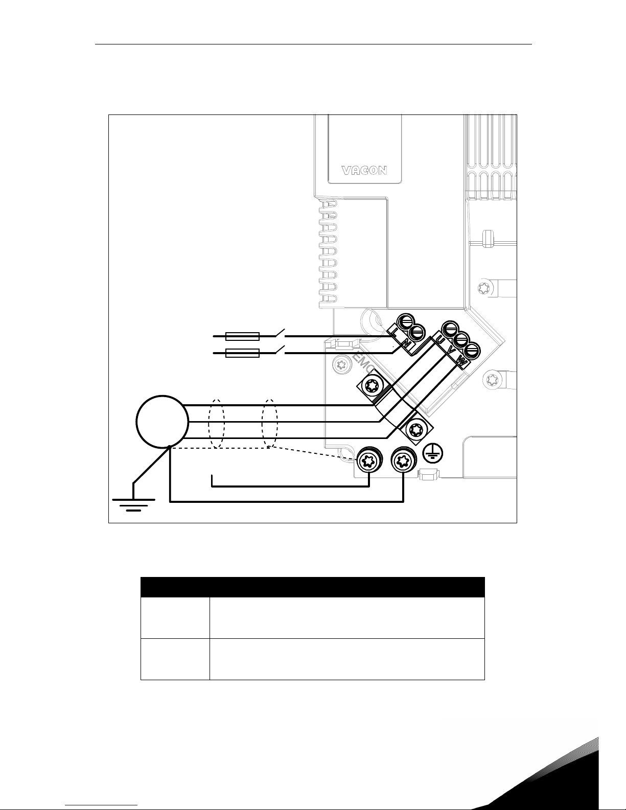
4.3.2 MS2 single-phase version power connections
Figure 20. Power connections, MS2 single-phase version.
Ter minal Description
L
N
These terminals are the input connections for the power
supply. Single-phase 230 VAC voltage has to be connected
to L and N terminals.
U
V
W
These terminals are for motor connections.
Table 15. Description of Vacon 20CP MS2 power terminals (single-phase version).
PES
PE
AC power supply
single phase
3AC
Motor
Page 42
4
vacon • 39 Power cabling
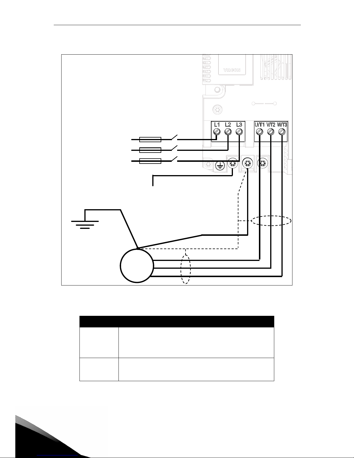
4.3.3 MS3 power connections
Figure 21. Power connections, MS3.
Ter minal Description
L1
L2
L3
These terminals are the input connections for the power
supply. 230 VAC models can be supplied by single-phase
voltage by connecting to L1 and L2 terminals (with derating of 50%).
U/T1
V/T2
W/T3
These terminals are for motor connections.
Table 16. Description of Vacon 20CP MS3 power terminals.
PES
PE
AC power supply
Single or
Three phases
3AC
Motor
Page 43
Power cabling vacon • 40
Service support: find your nearest Vacon service center at www.vacon.com
4
4.4 Cable dimensioning and selection
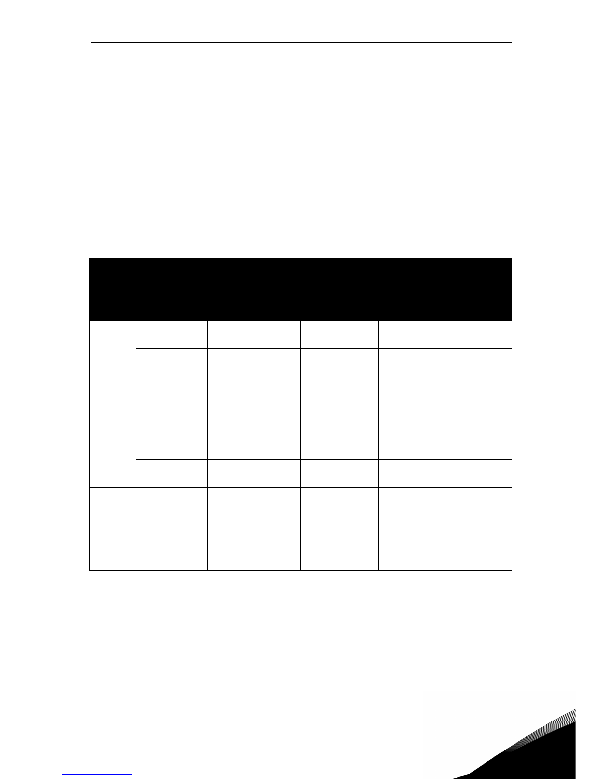
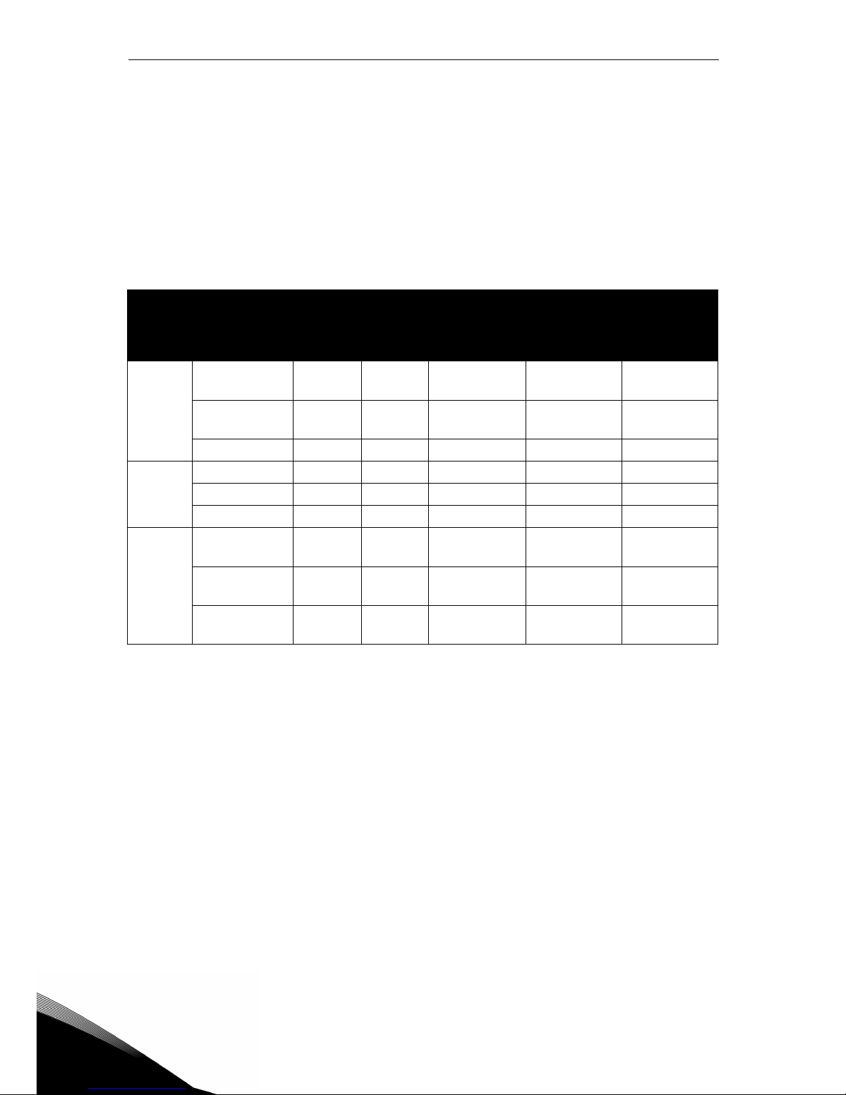
Table 17 shows the minimum dimensions of the Cu-cables and the corresponding fuse sizes.
These instructions apply only to cases with one motor and one cable connection from the AC
drive to the motor. In any other case, ask the factory for more information.
4.4.1 Cable and fuse sizes, frames MS2 to MS3
The recommended fuse types are gG/gL (IEC 60269-1) or class T (UL & CSA). The fuse voltage
rating should be selected according to the supply network. The final selection should be made
according to local regulations, cable installation conditions and cable specifications. Bigger
fuses than those recommended below shall not be used.
Check that the fuse operating time is less than 0.4 seconds. Operating time depends on used
fuse type and impedance of the supply circuit. Consult the factory about faster fuses. Vacon
also recommends high speed J (UL & CSA), aR (UL recognized, IEC 60269-4) and gS (IEC
60269-4) fuse ranges.
Table 17. Cable and fuse sizes for VACON® 20 CP.
The cable dimensioning is based on the criteria of the International Standard IEC60364-5-52: Cables
must be PVC-isolated; use only cables with concentric copper shield; Max number of parallel cables is 9.
When using cables in parallel,
NOTE HOWEVER that the requirements of both the cross-sectional area
and the max number of cables must be observed.
For important information on the requirements of the earthing conductor, see chapter Earthing and
earth fault protection of the standard.
For the correction factors for each temperature, see International Standard IEC60364-5-52.
Frame Type
I
INPUT
[A]
Fuse
(gG/gL)
[A]
Mains and
motor cable
Cu [mm
2
]
Terminal cable si z e
Main
terminal
[mm
2
]
Earth
terminal
MS2
0004 2
0003 4 - 0004 4
4.3
3.2 - 4.0
6
3*1.5+1.5
0.2 — 2.5
M4 ring
terminal
0005 2 - 0007 2
0005 4 - 0006 4
6.8 - 8.4
5.6 - 7.3
10
3*1.5+1.5
0.2 — 2.5
M4 ring
terminal
0008 4 9.6 10
3*2.5+2.5
0.2 — 2.5
M4 ring
terminal
MS2
1-phase
0004 2 8.3 20
(Mains) 2*1.5+1.5
(Motor) 3*1.5+1.5
0.2 — 2.5
stranded
M4 ring
terminal
0005 2 11.2 20
(Mains) 2*2.5+2.5
(Motor) 3*2.5+2.5
0.2 — 2.5
stranded
M4 ring
terminal
0007 2 14.1 25
(Mains) 2*2.5+2.5
(Motor) 3*2.5+2.5
0.2 — 2.5
stranded
M4 ring
terminal
MS3
0011 2
0009 4
13.4
11.5
16
3*2.5+2.5
0.5 — 16.0
M5 ring
terminal
0012 2
0012 4
14.2
14.9
20
3*2.5+2.5
0.5 — 16.0
M5 ring
terminal
0017 2
0016 4
20.6
20.0
25
3*6+6
0.5 — 16.0
M5 ring
terminal
Page 44
4
vacon • 41 Power cabling
4.4.2 Cable and fuse sizes, frames MS2 to MS3, North America
The recommended fuse types are gG/gL (IEC 60269-1) or class T (UL & CSA). The fuse voltage
rating should be selected according to the supply network. The final selection should be made
according to local regulations, cable installation conditions and cable specifications. Bigger
fuses than those recommended below shall not be used.
Check that the fuse operating time is less than 0.4 seconds. Operating time depends on used
fuse type and impedance of the supply circuit. Consult the factory about faster fuses. Vacon
also recommends high speed J (UL & CSA), aR (UL recognized, IEC 60269-4) and gS (IEC
60269-4) fuse ranges.
Table 18. Cable and fuse sizes for VACON® 20 CP, North America.
The cable dimensioning is based on the criteria of the Underwriters’ Laboratories UL508C:Cables must
be PVC-isolated; Max ambient temperature +30 °C, max temperature of cable surface +70 °C; Use only
cables with concentric copper shield; Max number of parallel cables is 9.
When using cables in parallel, NOTE HOWEVER that the requirements of both the cross-sectional area
and the max number of cables must be observed.
For important information on the requirements of the earthing conductor, see standard Underwriters’
Laboratories UL508C.
For the correction factors for each temperature, see the instructions of standard Underwriters’ Labo-
ratories UL508C.
Frame Type
I
INPUT
[A]
Fuse
(class T)
[A]
Mains and
motor cable
Cu
Terminal cable size
Main terminal
Earth
terminal
MS2
0004 2
0003 4 - 0004 4
4.3
3.2 - 4.0
6
AWG14 AWG24-AWG12 AWG17-AWG10
0005 2 - 0007 2
0005 4 - 0006 4
6.8 - 8.4
5.6 - 7.3
10
AWG14 AWG24-AWG12 AWG17-AWG10
0008 4 9.6 10
AWG14 AWG24-AWG12 AWG17-AWG10
MS2
1-phase
0004 2 8.3 20
AWG14 AWG24-AWG12 AWG17-AWG10
0005 2 11.2 20
AWG14 AWG24-AWG12 AWG17-AWG10
0007 2 14.1 25
AWG14 AWG24-AWG12 AWG17-AWG10
MS3
0011 2
0009 4
13.4
11.5
15
AWG14 AWG20-AWG6 AWG17-AWG10
0012 2
0012 4
14.2
14.9
20
AWG12 AWG20-AWG6 AWG17-AWG10
0017 2
0016 4
20.6
20.0
25
AWG10 AWG20-AWG6 AWG17-AWG10
Page 45

Power cabling vacon • 42
Service support: find your nearest Vacon service center at www.vacon.com
4
4.5 Brake resistor cables
VACON® 20 CP AC drives (three-phase version) are equipped with terminals for an optional external brake resistor. These terminals are 6.3 mm Faston for MS2 and spring-type terminals
for MS3. See Figure 23 and Figure 25 for the location of these terminals.
See Table 33 and Table 34 for the resistor ratings.
4.6 Control cables
For information on control cables see chapter Control unit cabling.
Page 46
4
vacon • 43 Power cabling
4.7 Cable installation
• Before starting, check that none of the components of the AC drive is live. Read the
warnings in chapter 1 carefully
• Place the motor cables sufficiently far from other cables
• Avoid placing the motor cables in long parallel lines with other cables.
• If the motor cables run in parallel with other cables note the minimum distances
between the motor cables and other cables given in table below.
• The given distances also apply between the motor cables and signal cables of other systems.
•The maximum length for motor cables is 30m
• The motor cables should cross other cables at an angle of 90 degrees.
• If cable insulation checks are needed, see chapter Cable and motor insulation checks.
Start the cable installation according to the instructions below:
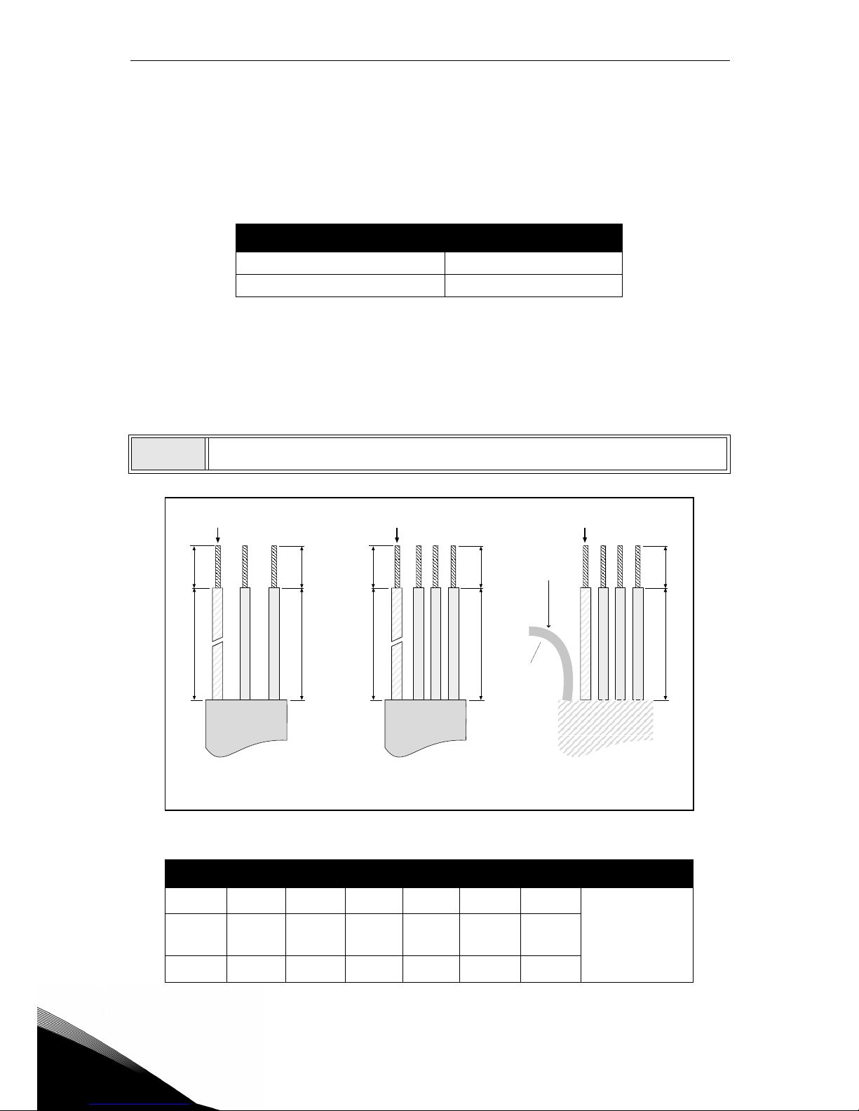
Figure 22. Stripping of cables.
Table 19. Cables stripping lengths [mm].
Distance between cables, [m] Shielded cable, [m]
0.3 ≤ 50
1.0 ≤ 200
1
Strip the motor and mains cables as recommended below.
Frame A1 B1 C1 D1 C2 D2 E
MS2 888203620
Leave as short
as possible
MS2
1-phase
788203620
MS3 888203620
D1
B1
C1
A1
D2
C2
E
Earth conductor
MAINS MOTOR
Shield
Earth conductor
D1
C1
Earth conductor
MAINS
(1-phase)
Page 47
Power cabling vacon • 44
Service support: find your nearest Vacon service center at www.vacon.com
4
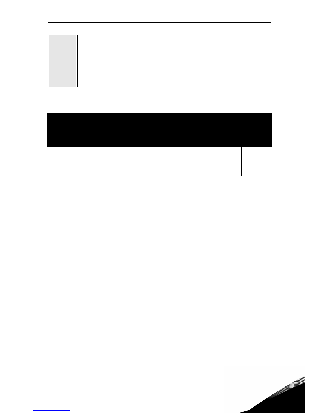
Tightening torques of cable terminals:
Table 20. Tightening torques of terminals.
2
Connect the stripped cables:
• Expose the shield of both cables in order to make a 360-degree connection
with the cable clamp.
• Connect the phase conductors of the supply and motor cables into their
respective terminals.
• Form the rest of the cable shield of both cables into “pigtails” and make a
grounding connection with the clamp. Make the pigtails just long enough
to reach and be fixed to the terminal - no longer.
Frame Type
Tightening torque
Power and motor
terminals
Tightening torque
EMC grounding
clamps
Tightening torque,
Grounding terminals
[Nm] lbs-in. [Nm] lbs-in. [Nm] lbs-in.
MS2
0003 4—0008 4
0004 2—0007 2
0.5—0.6 4.5—5.3 1.5 13.3 2.0 17.7
MS3
0009 4—0016 4
0011 2—0017 2
1.2—1.5 10.6—13.3 1.5 13.3 2.0 17.7
Page 48

4
vacon • 45 Power cabling
Page 49
Control unit vacon • 46
Service support: find your nearest Vacon service center at www.vacon.com
5
5. CONTROL UNIT
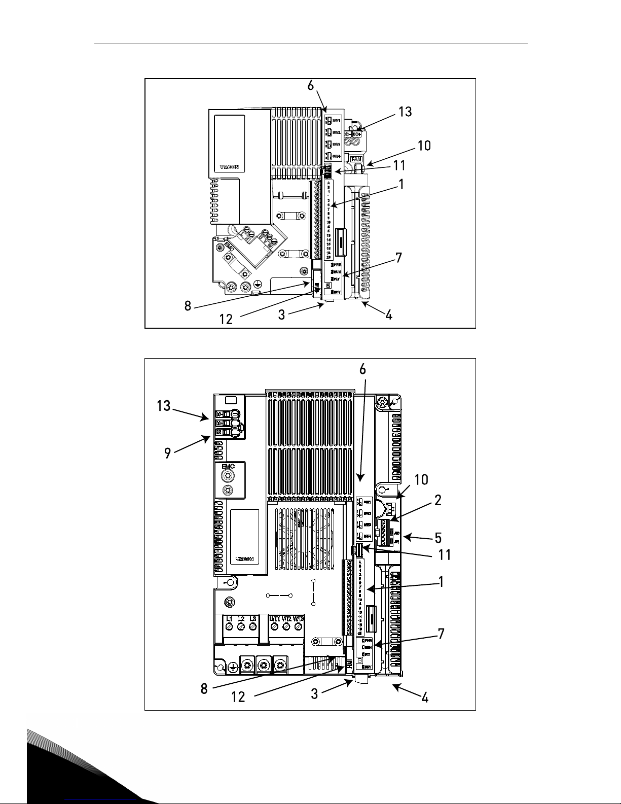
The control unit of the AC drive consists of the control board and additional boards (option
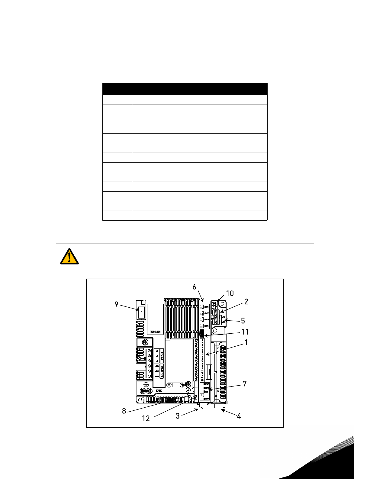
boards) connected to the slot connectors of the control board. The locations of boards, terminals and switches are presented in Figure 23, Figure 24 and Figure 25.
Figure 23. Locations of the components in control unit of MS2 (three-phase version).
Number Meaning
1 Control terminals A-20
2 STO terminals (only in three-phase version)
3 Relay terminals
4 Option board terminals
5 STO Jumpers (only in three-phase version)
6DIP switches
7Status LEDs
8 HMI connector (RJ45 keypad connector)*
9 Optional brake resistor terminals
10 Supply voltage connector for external fan
11 Control terminals A-20 echo connector
12 HMI echo connector (keypad connector)
13 DC-bus terminals
Table 21. Locations of components in control unit
*
The HMI connector is only to connect the keypad and not for Ethernet comunica-
tion.
Page 50
5
vacon • 47 Control unit
Figure 24. Locations of the components in control unit of MS2 (single-phase version).
Figure 25. Location of the components in the control unit of MS3.
Page 51
Control unit vacon • 48
Service support: find your nearest Vacon service center at www.vacon.com
5
When delivered from the factory, the control unit of the AC drive contains the standard controlling interface - the control terminals of the control board - unless otherwise specifically ordered. In the following pages you will find the arrangement of the control I/O and the relay
terminals, the general wiring diagram and the control signal descriptions.
The control board can be powered externally by connecting an external power source (about
130-150mA at 24VDC are needed to supply the control board without keypad, option board or
other loads) between terminal #6 and GND, see chapter 5.1.2. To ensure that the external supply works with any configurations we recommend to use an external supply of +24VDC ±10%,
1000mA overcurrent protected.
This voltage is sufficient for parameter setting and for keeping the control unit active. Note
however that the values of the measurements of the main circuit (e.g. DC-link voltage, unit
temperature) are not available when the mains is not connected.
In addition to the internal fan, VACON
®
20 CP frequency converters include an auxiliary fan
power supply connector (see 10 in the Figure 23, Figure 24 and Figure 25) for improved air flow
and system cooling. The power supply also has automatic thermal switching on/off control: it
automatically switches on/off depending on internal cold plate temperature. The electric specifications for the auxiliary fan power supply are shown in the following table:
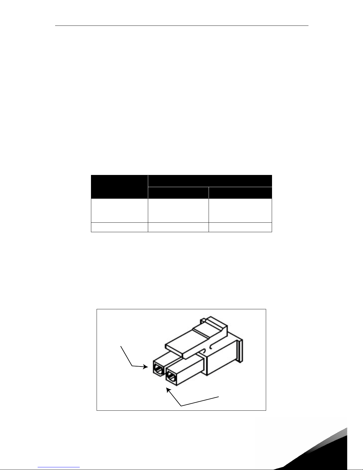
The connector for the auxiliary fan supply is a Micro-Fit 3.0
TM
Header, Surface Mount Compatible, Single Row, Vertical with PCB Polarizing Peg by Molex (part number 43650-0215). This
connection is echoed in the HMI echo connector. See Figure 23, Figure 24 and Figure 25 for the
location of the connectors and Table 28 for the description of the HMI echo terminal.
To connect the auxiliary fan to VACON
®
20 CP drives you will need a Micro-Fit 3.0™ Receptacle
Crimp Housing, Single Row by Molex
®
(part number 43645-0200). See the picture below for
more details.
Figure 26. Micro-Fit 3.0™ Housing.
Terminals
SIgnals
MS2 MS3
FAN+
24VDC ±10%
maximum output
current 200mA
24VDC ±10%
maximum output current 700mA
FAN- GND GND
Table 22. Electric specifications for the auxiliary fan power supply.
FAN+
FAN-
Page 52
5
vacon • 49 Control unit
5.1 Control unit cabling
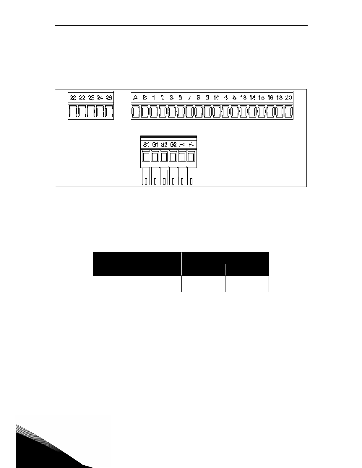
The principal terminal block placement is shown in Figure 27 below. The control board is
equipped with 23 fixed control I/O terminals. Additionally, the terminals for the Safe Torque Off
(STO) function (see chapter 9) can be seen in the picture below. All signal descriptions are also
given in Table 24.
Figure 27. Control terminals.
5.1.1 Control cable sizing
The control cables shall be at least 0.14 mm
2
screened multi core cables, see Table 23. The
maximum terminal wire size for the I/O terminals is 1.5 mm
2
.
Find the tightening torques of the I/O (control and relays) and STO terminals in the Table below.
Terminal screw
Tightening torque
Nm lbs-in.
I/O terminals and STO terminals (screw M2)
0.22 min
0.25 max
1.95 min
2.21 max
Table 23. Control cable tightening torques.
Page 53
Control unit vacon • 50
Service support: find your nearest Vacon service center at www.vacon.com
5
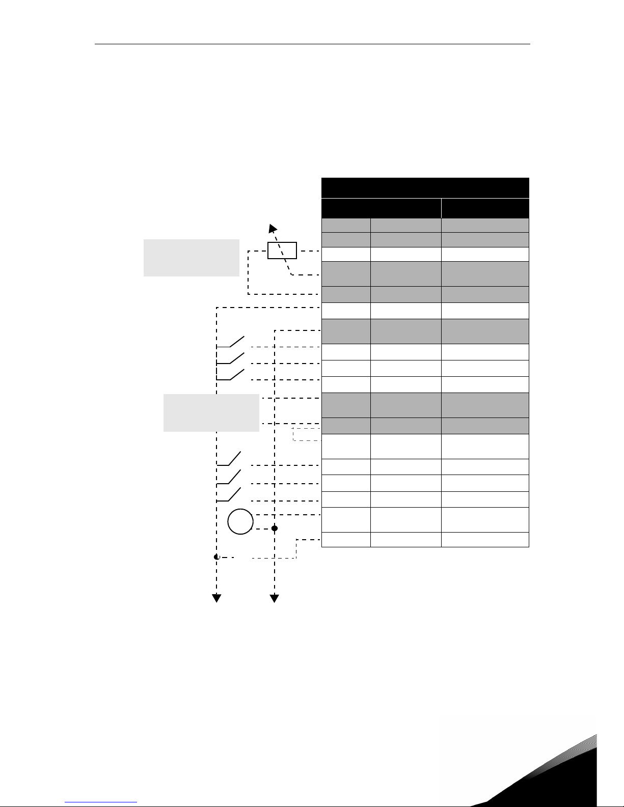
5.1.2 Standard I/O terminals
The terminals of the
Standard I/O are described below. For more information on connections,
see chapter 7.3.1.
The terminals shown on shadowed background are assigned for signals with optional functions
selectable with DIP switches. For more information, see chapter 5.1.7.
Table 24. Control I/O terminal signals and connection example.
Standard I/O terminals
Terminal Signal
A RS485_A Serial bus, negative
B RS485_B Serial bus, positive
1 +10 Vref Reference output
2
AI1+
Analogue input,
voltage or current
3
GND I/O signal ground
6
24Vout 24V aux. voltage
7
DIN COM
Digital inputs common
8
DI1 Digital input 1
9
DI2 Digital input 2
10
DI3 Digital input 3
4
AI2+
Analogue input,
voltage or current
5
GND I/O signal ground
13
DO1-
Digital output 1 common
14
DI4 Digital input 4
15
DI5 Digital input 5
16
DI6 Digital input 6
18
AO1+
Analogue signal
(+output)
20 DO1+ Digital output 1
V
X1
Remote reference
4...20mA/0...10V
Reference potentiometer
1...10kΩ
Page 54
5
vacon • 51 Control unit
5.1.3 Relay terminals
5.1.4 Safe Torque off (STO) terminals
For more information on the functionalities of the Safe Torque Off (STO), see chapter 9. This
function is available only in the three-phase version.
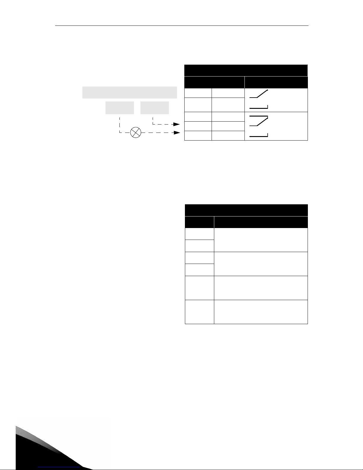
Table 25. I/O terminal signals for relays and connection example.
Relays terminals
Terminal Signal
22
RO1/2
Relay output 1
23
RO1/3
24
RO2/1
Relay output 2
25
RO2/2
26
RO2/3
Table 26. I/O terminal signals for the STO functions.
Safe Torque Off terminals
Ter minal Signal
S1
Isolated digital input 1 (interchangeable polarity);
+24V ±20% 10...15mA
G1
S2
Isolated digital input 2 (interchangeable polarity);
+24V ±20% 10...15mA
G2
F+
Isolated feedback (CAUTION!
Polarity to be respected);
+24V ±20%
F-
Isolated feedback (CAUTION!
Polarity to be respected);
GND
From
standard I/O board
From term.
#7
From term.
#6
RUN
Page 55
Control unit vacon • 52
Service support: find your nearest Vacon service center at www.vacon.com
5
5.1.5 Description of additional echo connectors
In this paragraph you will find the description of the additional echo connectors for the I/O terminals and for the HMI.
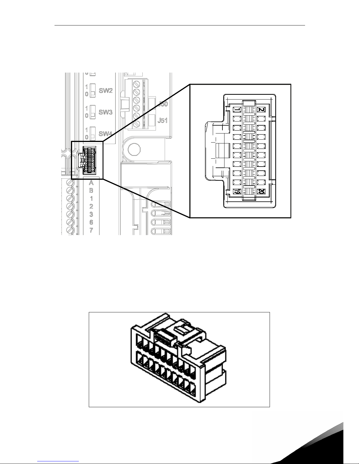
Figure 28. The I/O remote echo connector mounted on the control board.
In Figure 28 the view of Molex® connector for the I/O terminals is shown. In the control unit the
position of this connector is numbered with 11 as shown in Figure 23 and Figure 25. The type
of this connector is Pico-Clasp™ Wire-to Board PCB Header, Dual Row, RIght Angle. The code
by Molex
®
is: 501571-2007.
It mates with Pico-Clasp™ Wire-to Board Receptacle Housing (crimp housing), Dual Row, 20
Circuits. The code by Molex
®
is: 501189-2010. See Figure 29.
Figure 29. Receptacle housing for I/O remote echo connector.
Page 56
5
vacon • 53 Control unit
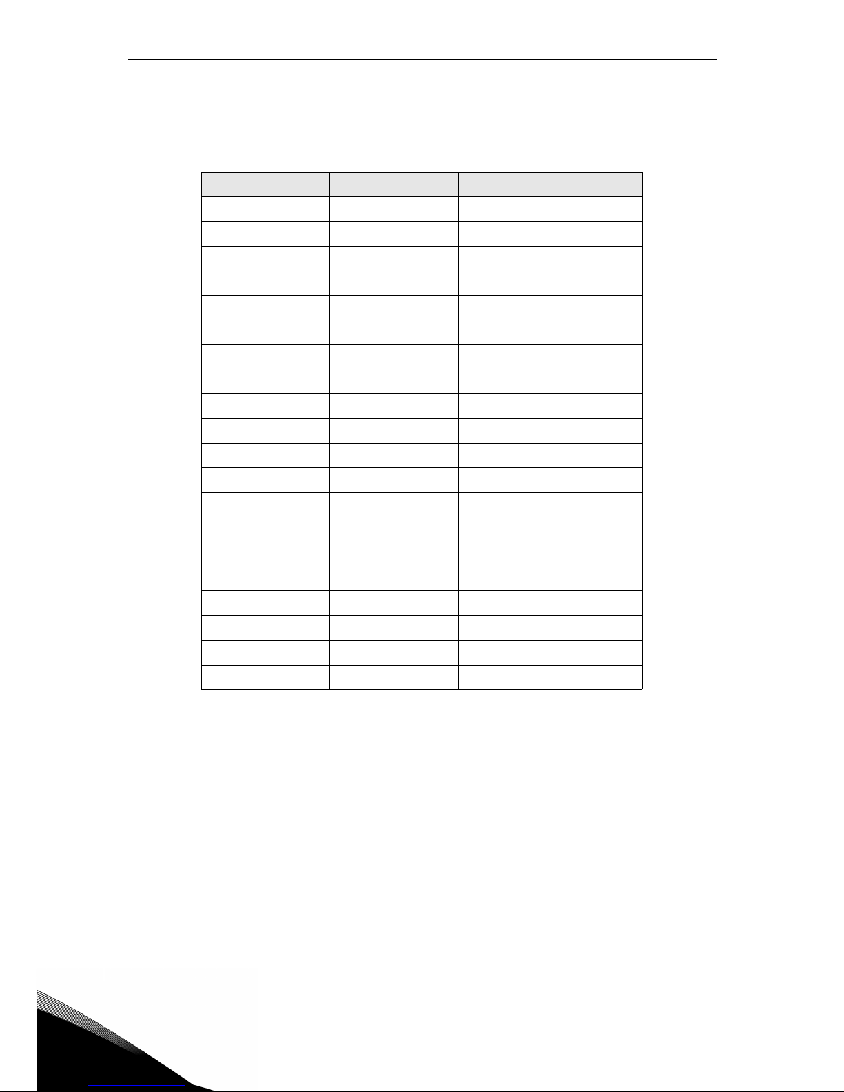
To connect I/Os to the control unit through echo terminals this connector has to be used. In the
following table, the correspondence between the pins of this connector and the VACON
®
20 CP
terminals is shown.
Pin number Signal Description
1 RS485_B Serial bus, positive
2 DI2 Digital input 2
3 RS485_A Serial bus, negative
4 DI3 Digital input 3
5 NC not connected
6AI2+
7 NC not connected
8GND
9 +10Vref
10 DO1- common for digital output 1
11 AI1+
12 DI4 Digital input 4
13 GND
14 DI5 Digital input 5
15 24Vout
16 DI6 Digital input 6
17 DIN COM
18 AO1+ Analogue output 1
19 DI1 Digital input 1
20 DO1+ Digital output 1
Table 27. I/O remote connector description.
Page 57
Control unit vacon • 54
Service support: find your nearest Vacon service center at www.vacon.com
5
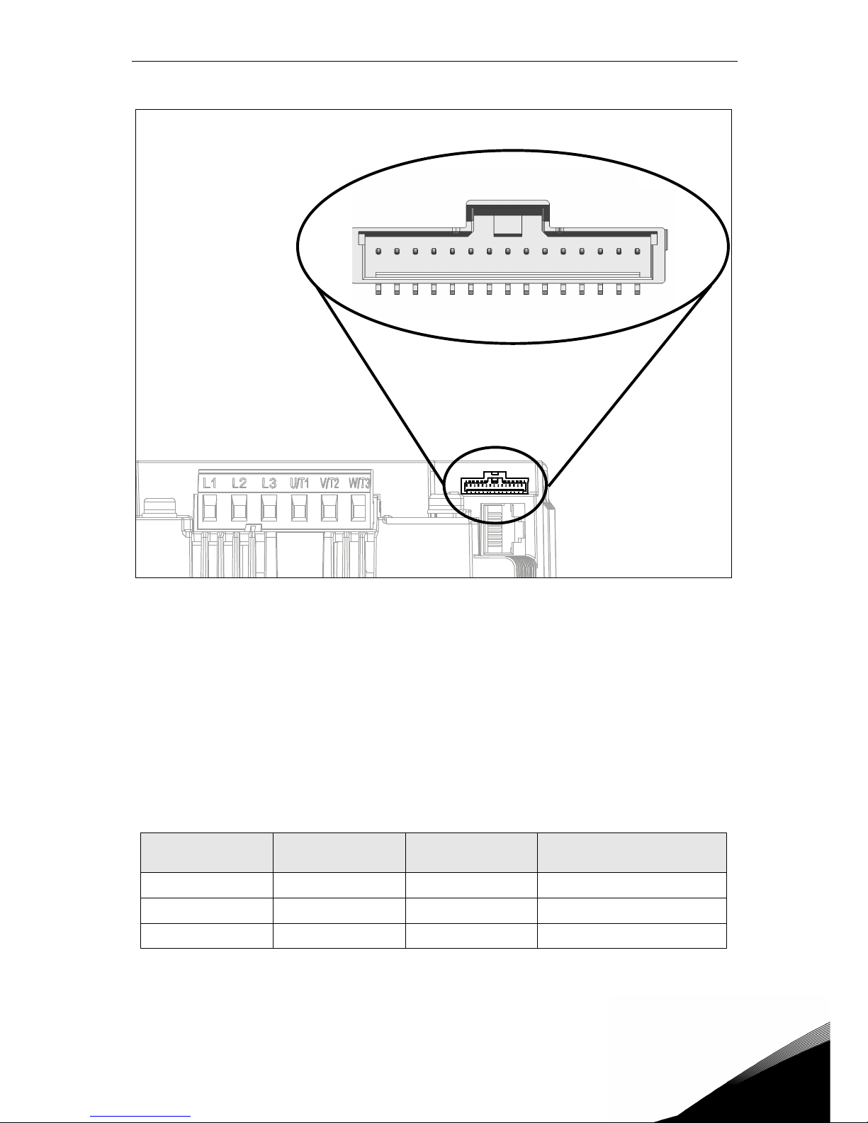
Figure 30. HMI remote connector.
In Figure 30 the view of Molex® connector for the HMI terminals is shown. In the control box
the position of this connector is numbered with 8, as shown in Figure 23 and Figure 25. The
type of connector is Pico-Clasp™ Wire-to-Board Header, Surface Mount, Single Row, Vertical,
with Positive Lock. The code by Molex
®
is: 501331-1507.
It mates with Pico-Clasp™ Wire-to Board Female Housing (crimp housing), Single Row, with
Positive lock, 15 Circuits. The code by Molex
®
is: 501330-1500.
To connect HMI to the control unit through echo terminals this connector has to be used. In the
following table, the correspondence between the pins of this connector and the VACON
®
20 CP
HMI terminals is shown.
Pin number in RJ45
connector
Pin number of echo
connector
Signal Description
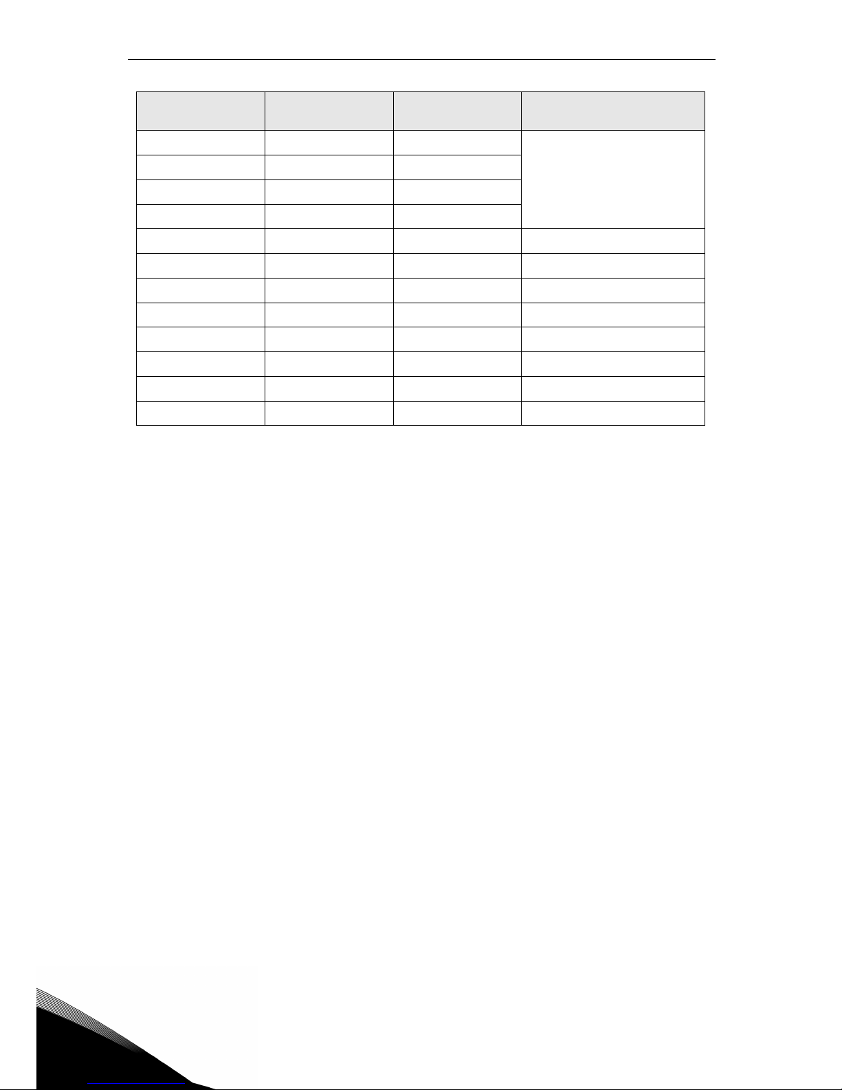
2 15 +24V Panel supply
6 14 +3.3V Panel supply
5 13 GND ground
Table 28. HMI remote connector description with RJ45 correspondences.
15 14 13 12 11 10 9 8 7 6 5 4 3 2 1
Page 58
5
vacon • 55 Control unit
112Keyp_TX+
RS422 (connection for panel
communication)
4 11 Keyp_TX-
3 10 Keyp_RX+
79Keyp_RX-
8 8 Led_CTRL1 Control signal for LED1
- 7 Led_CTRL2 Control signal for LED2
- 6 Led_CTRL3 Control signal for LED3
- 5 FAN+ External FAN+(+24V)
- 4 FAN- GND for external FAN
- 3 nc not connected
- 2 nc not connected
- 1 nc not connected
Pin number in RJ45
connector
Pin number of echo
connector
Signal Description
Table 28. HMI remote connector description with RJ45 correspondences.
Page 59
Control unit vacon • 56
Service support: find your nearest Vacon service center at www.vacon.com
5
5.1.6 Led handling
As VACON
®
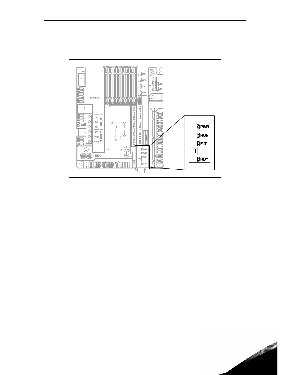
20 Cold plate is often without the keypad, on the plastic cover of the drive there are
4 status LEDs. See the picture below.
Figure 31. LED position on the MS2 cover.
Led “PWR” (orange led) means the drive is supplied by mains.
Led “RUN” (green led) means the drive is running.
Led “FLT” (red led) means the drive is experiencing a fault.
Led “RDY” (orange led) means the drive is ready and no fault is present. When a Warning is ac-
tive, the led starts blinking.
Page 60
5
vacon • 57 Control unit
5.1.7 Selection of terminal functions with dip switches
VACON
®
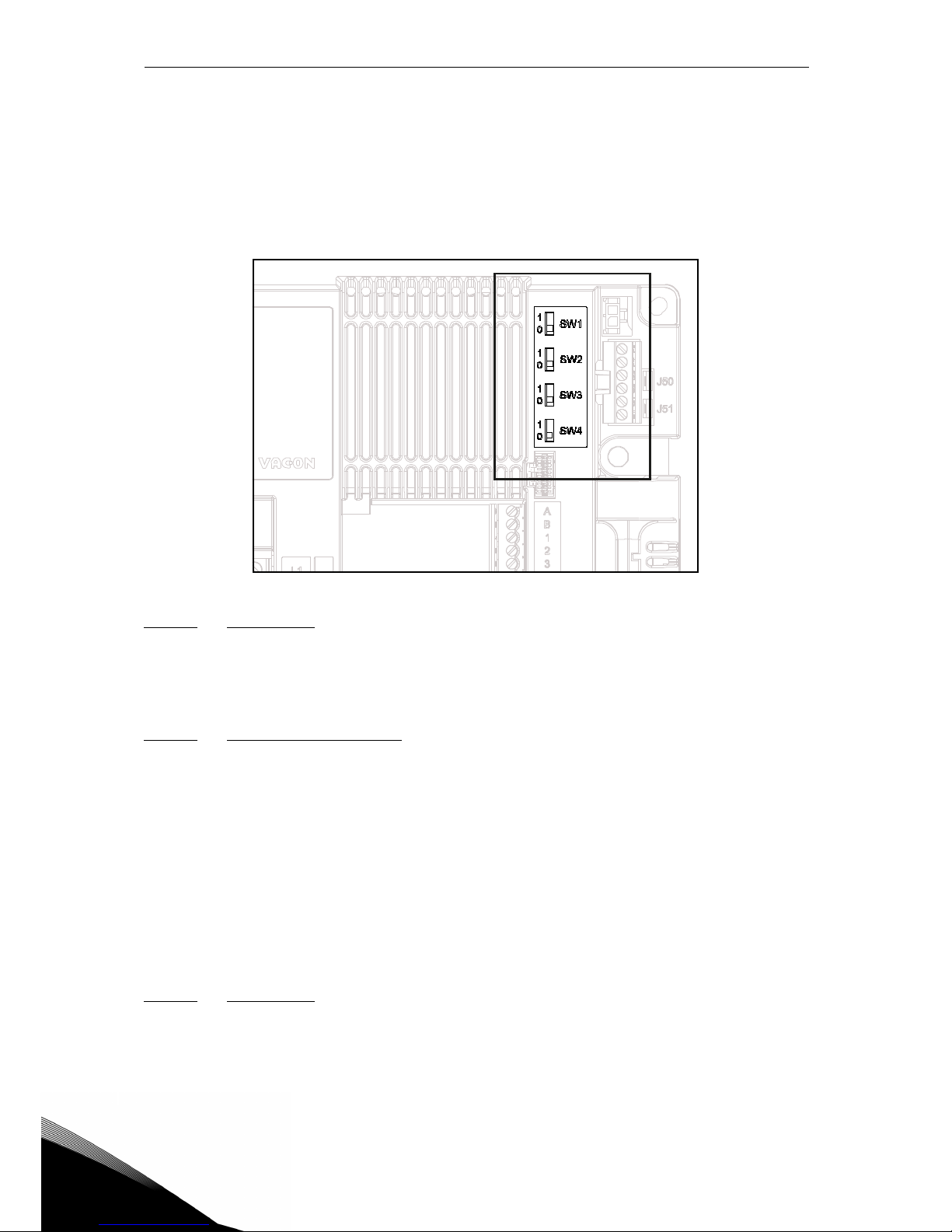
20 Cold Plate drive embodies four so-called switches that allow for two functional selections each. The shadowed terminals in Table 24 can be functionally modified with the dip
switches.
The switches have two positions: 0 and 1. See Figure 32 to locate the switches and make appropriate selections for your requirements.
Figure 32. Dip switches
5.1.7.1
Switch SW1
The digital inputs (terminals 8-10 and 14-16) on the standard I/O board can be isolated from
ground by setting the
dip switch SW1 to position ‘1’. See Figure 32. Locate the switch and set
it in the desired position. The switch in the position “0” means that the common of digital input
have been connected to the ground.The default position is “0”.
5.1.7.2 Switches SW2 and SW3
Analogue inputs can be used as either current inputs or voltage inputs. The signal type is selected with two switches on the control board.
The switch SW2 is related to analogue input AI1. In position “1” the analogue input AI1 works
in voltage mode. In position “0” the analogue input works in current mode. The default position
for SW2 is “1”.
The voltage range is 0...10V and the current is 0/4.....20 mA.
The switch SW3 is related to analogue input AI2. In the position “1” the analogue input AI2
works in voltage mode. In the position “0” the analogue input works in current mode. The default position for SW3 is “0”.
The voltage range is 0...10V and the current is 0/4.....20 mA.
5.1.7.3 Switch SW4
The switch SW4 is related to the RS485 connection. It’s used for bus termination. The bus termination must be set to the first and to the last device on the network. The switch SW4 in position “0” means that termination resistance is connected and the termination of the bus has
been set. If the Vacon 20 CP is the last device on the net, this switch must be set to “0” position.
The default position for SW4 is “0”.
Page 61
Control unit vacon • 58
Service support: find your nearest Vacon service center at www.vacon.com
5
5.2 Fieldbus connection
Modbus is a communication protocol developed by Modicon systems. In other words, it is a way
of sending information between electronic devices. The device requesting the information is
called the Modbus Master and the devices supplying information are Modbus Slaves. In a standard Modbus network, there is one Master and up to 247 Slaves, each with a unique Slave Address from 1 to 247. The Master can also write information to the Slaves. Modbus is typically
used to transmit signals from instrumentation and control devices back to a main controller
or data gathering system.
The Modbus communication interface is built around messages. The format of these Modbus
messages is independent of the type of physical interface used. The same protocol can be used
regardless of the connection type. Thanks to this, Modbus allows for the easy upgrade of the
hardware structure of an industrial network, without the need for significant changes in the
software. A device can also communicate with several Modbus nodes at once, although they
are connected with different interface types, without the need to use a different protocol for every connection.
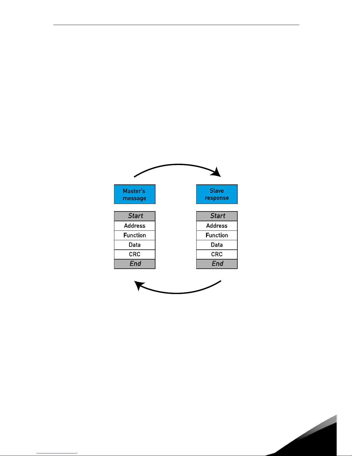
Figure 33.Basic structure of Modbus frame.
On simple interfaces such as RS485, the Modbus messages are sent in plain form over the network. In this case the network is dedicated to Modbus.
Each Modbus message has the same structure. Four basic elements are present in each message. The sequence of these elements is the same for all messages, to make it easy to parse
the content of the Modbus message. A conversation is always started by a master in the Modbus network. A Modbus master sends a message and — depending on the contents of the message — a slave takes action and responds to it. There can be more masters in a Modbus
network. The address in the message header is used to define which device should respond to
a message. All other nodes on the Modbus network ignore the message if the address field
doesn't match their own address.
Page 62
5
vacon • 59 Control unit
5.2.1 Modbus RTU protocol
VACON
®
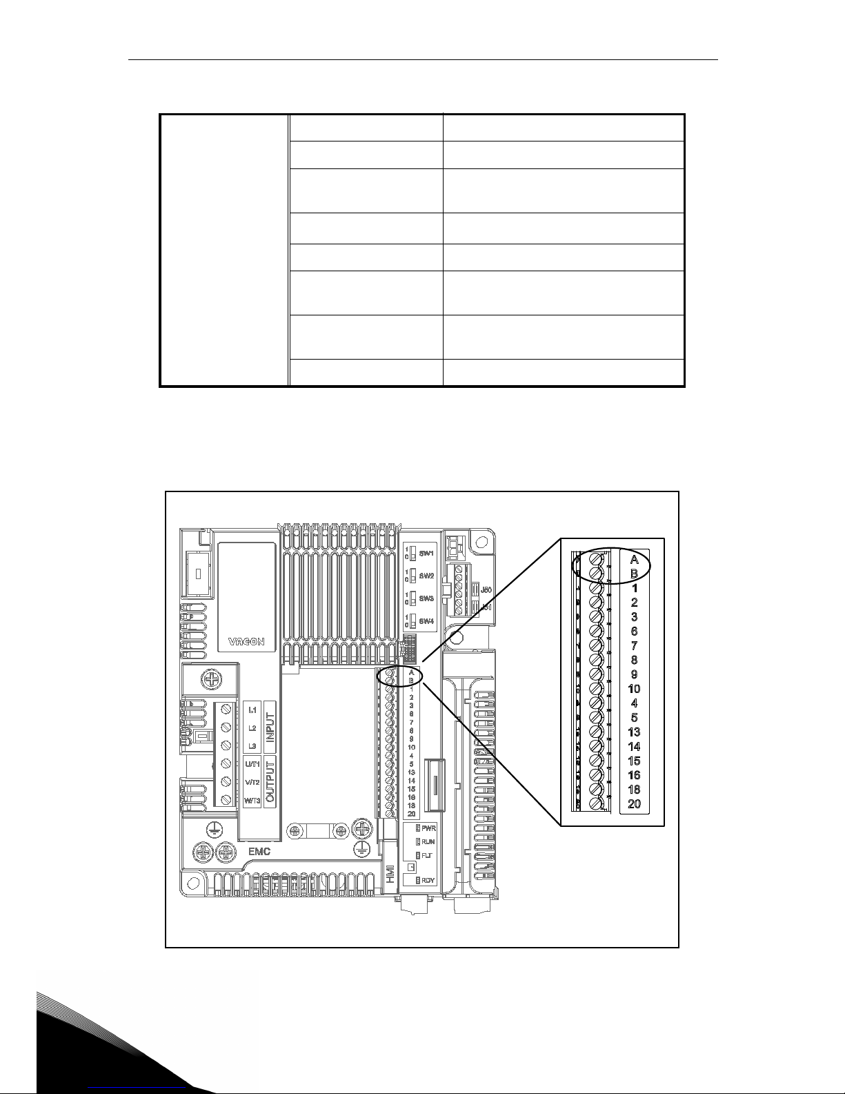
20 CP drive is equipped with Modbus support as standard. The AC drive can be connected to fieldbus through RS485. The connection for RS485 is on the standard I/O (terminals
A and B). See Figure 34.
Figure 34. Position of the RS485 terminals on the I/O standard terminal connector.
Connections and
communications
Interface RS-485
Data transfer method RS-485 MS/TP, half-duplex
Transfer cable
STP (shielded twisted pair), type
Belden 9841 or similar
Connector
2.5 mm
2
Electrical isolation Functional
Modbus RTU
As described in “Modicon Modbus
Protocol Reference Guide”
Baud rate
300, 600, 1200, 2400, 4800, 9600,
19200, 38400 and 57600 baud
Addresses 1 to 247
Table 29.
Page 63
Control unit vacon • 60
Service support: find your nearest Vacon service center at www.vacon.com
5
5.2.2 Preparation for use through RS485
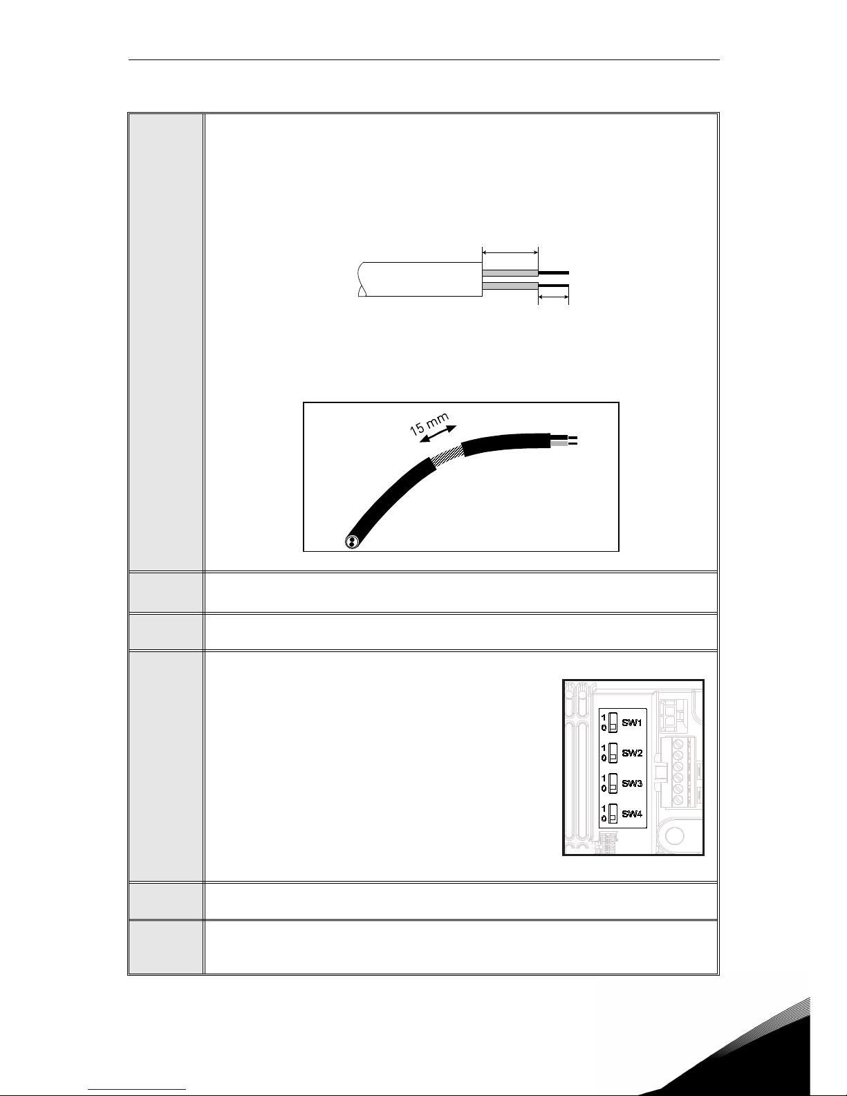
1
Strip about 15 mm of the RS485 cable (see specification on Table 29) and cut off
the grey cable shield. Remember to do this for both bus cables (except for the
last device).
Leave no more than 10 mm of the cable outside the terminal block and strip the
cables at about 5 mm to fit in the terminals. See picture below.
Also strip the cable now at such a distance from the terminal that you can fix it to
the frame with the grounding clamp. Strip the cable at a maximum length of 15
mm. Do not strip the aluminium cable shield!
2
Then connect the cable to its appropriate terminals on VACON® 20 CP AC drive
standard terminal block, terminals A and B (A = negative, B = positive).
3
Using the cable clamp included in the supply of the drive, ground the shield of
the RS485 cable to the frame of the AC drive.
4
If VACON® 20 Cold Plate drive is the last device on
the bus, the bus termination must be set. Locate the
switches to the right of the control terminals (see
Figure 32) and turn the SW4 switch to position “0”.
Biasing is built in the termination resistor.
5
NOTE: When planning the cable runs, remember to keep the distance between
the fieldbus cable and the motor cable at a minimum of 30 cm.
6
The bus termination must be set for the first and the last device of the fieldbus
line. We recommend that the first device terminated is the Master device.
10
5
Page 64

5
vacon • 61 Control unit
Page 65
Commissioning vacon • 62
Service support: find your nearest Vacon service center at www.vacon.com
6
6. COMMISSIONING
Before commissioning, note the following directions and warnings:
Internal components and circuit boards of VACON® 20 CP drive (except for the
galvanically isolated I/O terminals) are live when it is connected to mains potential. Coming into contact with this voltage is extremely dangerous and may
cause death or severe injury.
The motor terminals U, V, W and the brake resistor terminals are live when
VACON
®
20 CP drive is connected to mains, even if the motor is not running.
The control I/O-terminals are isolated from the mains potential. However, the
relay outputs and other I/O-terminals may have a dangerous control voltage
present even when VACON
®
20 CP drive is disconnected from mains.
Do not make any connections to or from the frequency converter when it is connected to the mains.
After disconnecting the AC drive from the mains, wait until the indicators on the
cover go out. Wait additional 30 seconds before doing any work on the connec-
tions of VACON
®
20 CP drive. Do not open the unit before this time has expired.
After expiration of this time, use a measuring equipment to absolutely ensure
that no
voltage is present.
Always ensure absence of voltage before starting any
electrical work!
Page 66
6
vacon • 63 Commissioning
6.1 Commissioning of the drive
Read carefully the safety instructions in Chapter 1 and above and follow them.
After the installation:
Check that both the frequency converter and the motor are grounded.
Check that the mains and motor cables comply with the requirements given in
chapter 4.
Check that the control cables are located as far as possible from the power cables,
see chapter 4.4.
Check that the shields of the shielded cables are connected to protective earth
marked with .
Check the tightening torques of all terminals.
Check that the wires do not touch the electrical components of the drive.
Check that the common inputs of digital input groups are connected to +24V or
ground of the I/O terminal.
Check the quality and quantity of cooling air.
Check the inside of the frequency converter for condensation.
Check that all Start/Stop switches connected to the I/O terminals are the in Stopposition.
Before connecting the frequency converter to mains: Check mounting and condition of all fuses and other protective devices.
Page 67
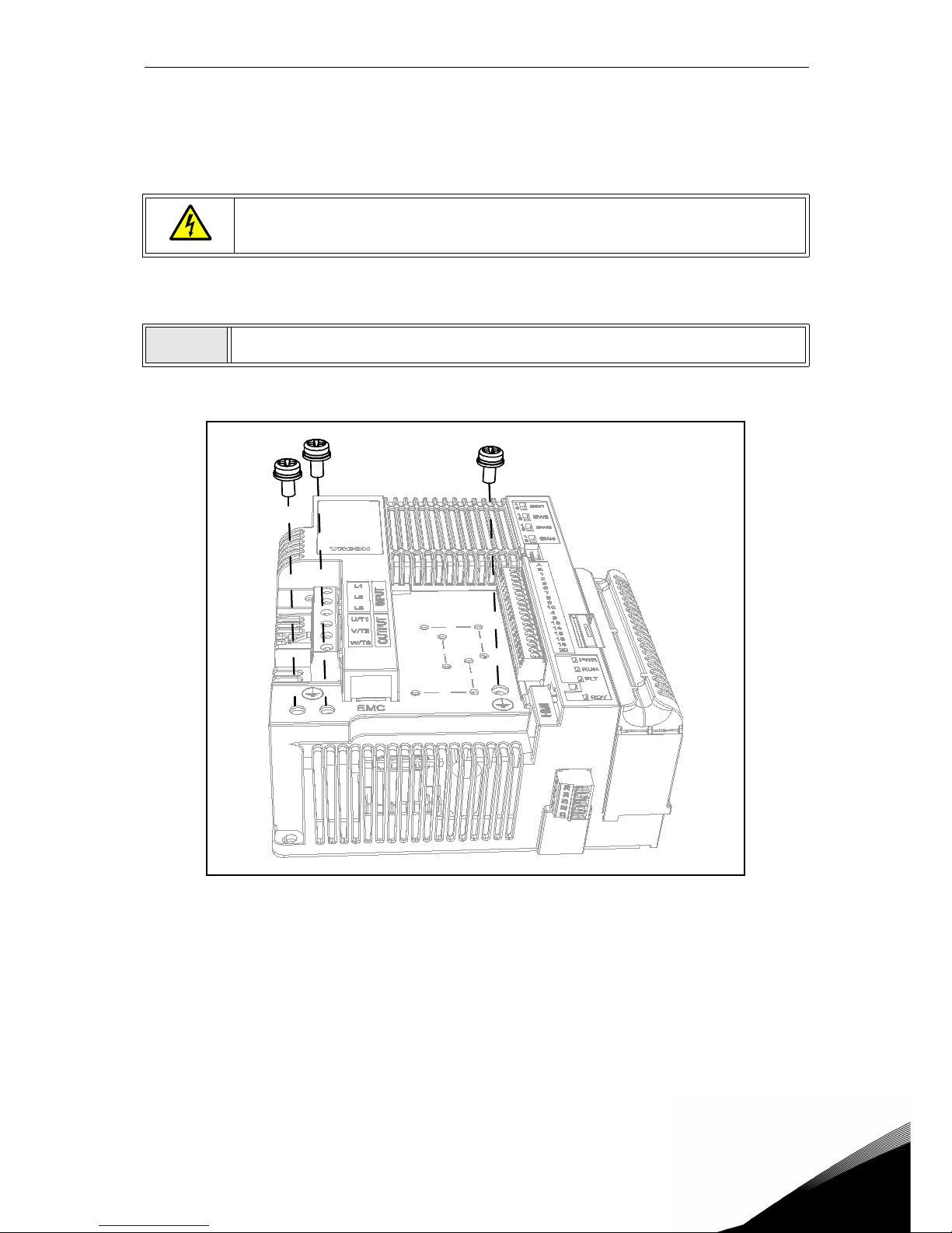
Commissioning vacon • 64
Service support: find your nearest Vacon service center at www.vacon.com
6
6.2 Changing EMC protection class
If your supply network is an IT (impedance-grounded) system but your AC drive is EMC-protected according to class C1 or C2 you need to modify the EMC protection of the AC drive to
EMC-level T (C4). This is done as described below:
6.2.1 Changing EMC protection class - MS2 three-phase version
Figure 35.Changing of the EMC class in MS2 (three-phase version).
Warning! Do not perform any modifications on the AC drive when it is connected
to mains.
1
Remove the three screws on the EMC plate from the unit.
Page 68
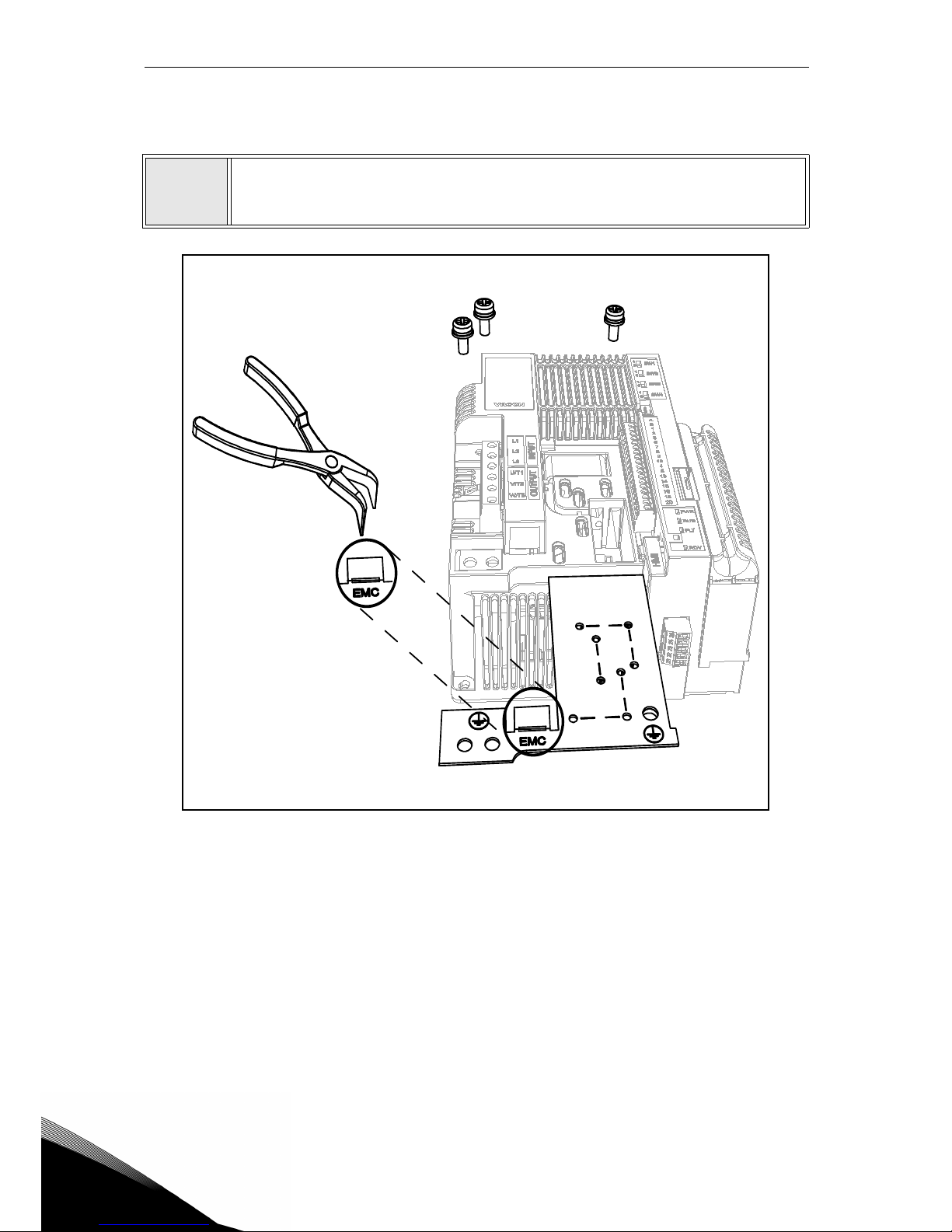
6
vacon • 65 Commissioning
Figure 36. Changing of the EMC class in MS2 (three-phase version).
2
Remove the EMC plate from the unit. Then lift the plate with pliers to disconnect
the EMC plate from the ground. See Figure 36.
Then reconnect the EMC plate to the unit.
Page 69
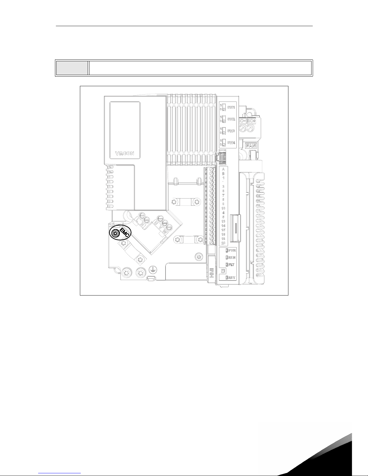
Commissioning vacon • 66
Service support: find your nearest Vacon service center at www.vacon.com
6
6.2.2 Changing EMC protection class - MS2 single-phase version
Figure 37. Changing the EMC class in the MS2 (single-phase version).
1
Remove the EMC screw as shown in the Figure 37.
Page 70
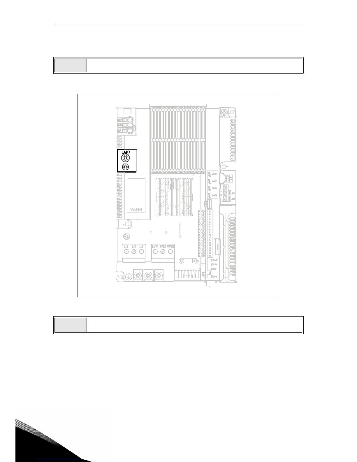
6
vacon • 67 Commissioning
6.2.3 Changing EMC protection class - MS3
Figure 38. Changing the EMC class in the MS3.
1
Remove the EMC screw as shown in the Figure 38.
CAUTION! Before connecting the AC drive to mains make sure that the EMC protection class settings of the drive are appropriately made.
Page 71
Commissioning vacon • 68
Service support: find your nearest Vacon service center at www.vacon.com
6
6.3 Running the motor
MOTOR RUN CHECK LIST
6.3.1 Cable and motor insulation checks
1. Motor cable insulation checks
Disconnect the motor cable from terminals U, V and W of the AC drive and from the motor.
Measure the insulation resistance of the motor cable between each phase conductor as
well as between each phase conductor and the protective ground conductor. The insulation resistance must be >1MΩ at ambient temperature of 20°C.
2. Mains cable insulation checks
Disconnect the mains cable from terminals L1 (L), L2 (N) and L3 of the AC drive and from
the mains. Measure the insulation resistance of the mains cable between each phase conductor as well as between each phase conductor and the protective ground conductor. The
insulation resistance must be >1MΩ at ambient temperature of 20°C.
3. Motor insulation checks
Disconnect the motor cable from the motor and open the bridging connections in the
motor connection box. Measure the insulation resistance of each motor winding. The
measurement voltage must equal at least the motor nominal voltage but not exceed 1000
V. The insulation resistance must be >1MΩ at ambient temperature of 20°C.
Before starting the motor, check that the motor is mounted properly and ensure
that the machine connected to the motor allows the motor to be started.
Set the maximum motor speed (frequency) according to the motor and the
machine connected to it.
Before reversing the motor make sure that this can be done safely.
Make sure that no power correction capacitors are connected to the motor cable.
Make sure that the motor terminals are not connected to mains potential.
Page 72
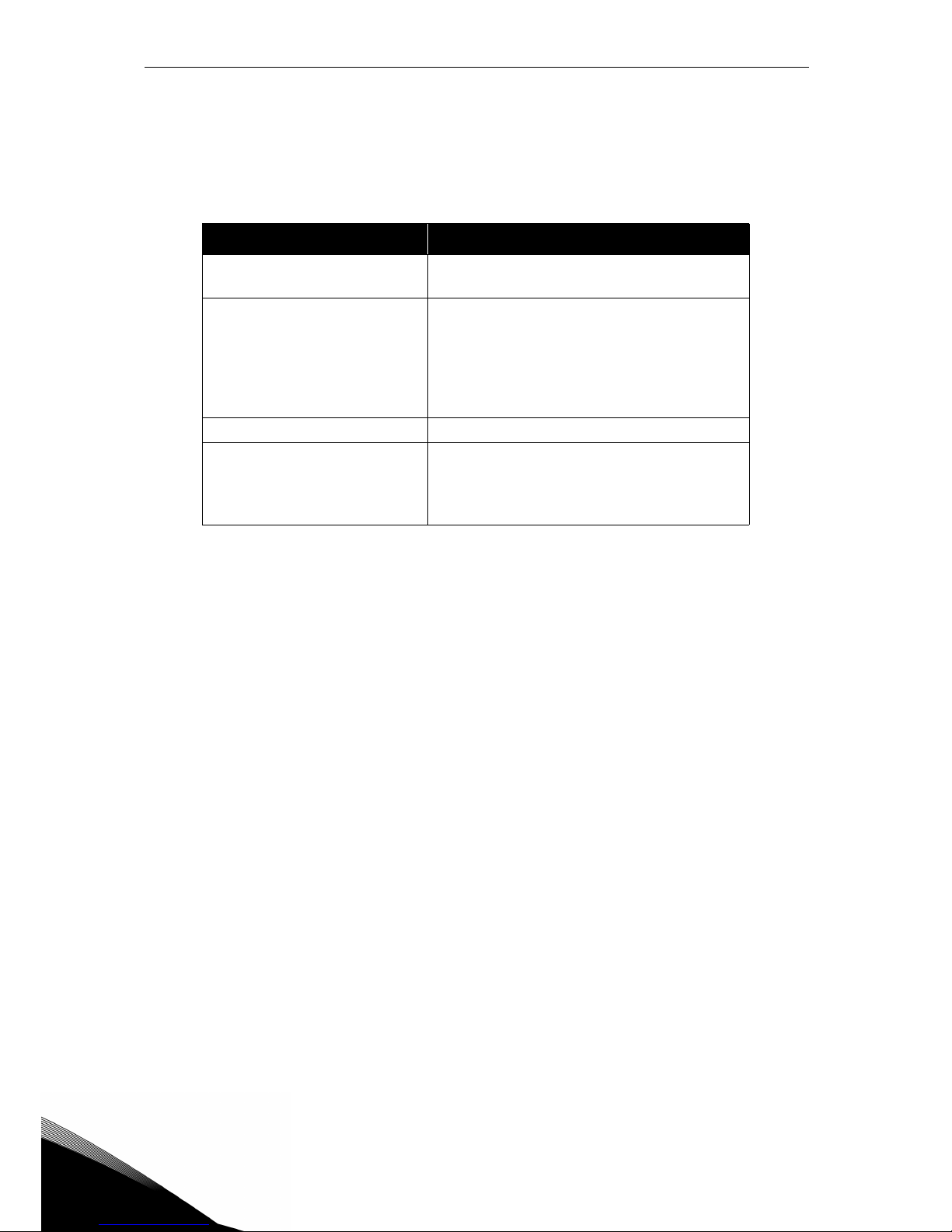
6
vacon • 69 Commissioning
6.4 Maintenance
In normal conditions, the AC drive is maintenance-free. However, regular maintenance is recommended to ensure trouble-free operation and longevity of the drive. We recommend the table below is followed for maintenance intervals.
Maintenance interval Maintenance action
Regularly and according to
general maintenance interval
• Check tightening torques of terminals
6...24 months (depending on
environment)
• Check input and output terminals and
control I/O terminals.
• Check for corrosion on terminals and
other surfaces
• Check door filter in case of cabinet
installation
24 months • Clean heatsink
12...24 months
• Charge capacitors, only after long
storage times or long down times
without supply: contact your nearest
Vacon service center
Page 73
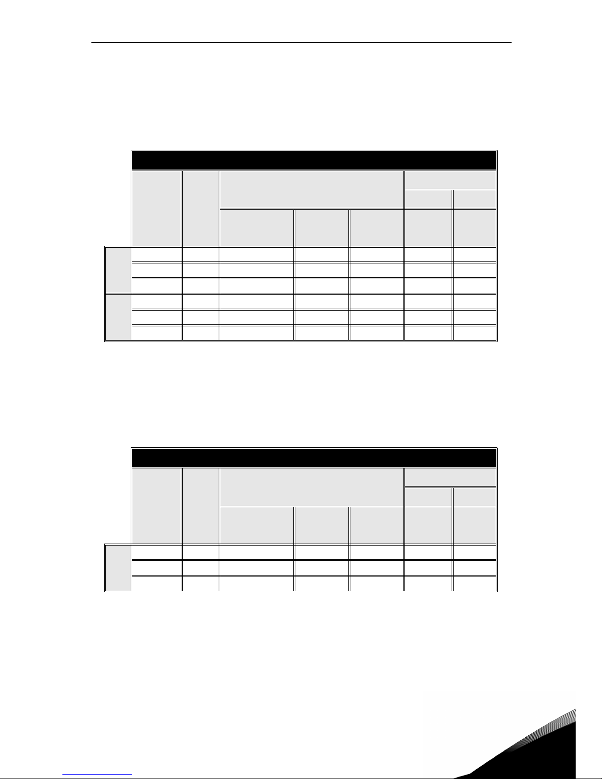
Technical data vacon • 70
Service support: find your nearest Vacon service center at www.vacon.com
7
7. TECHNICAL DATA
7.1 AC drive power ratings
7.1.1 Mains voltage 3AC 208-240V
Table 30. Power ratings of VACON® 20 CP, supply voltage 3AC 208-240V.
NOTE: The rated currents in given ambient temperatures (in Table 30) are achieved only when
the switching frequency is equal to or less than the factory default.
7.1.2 Mains voltage 1AC 208-240V
Table 31. Power ratings of VACON® 20 CP, supply voltage 1AC 208-240V.
NOTE: The rated currents in given ambient temperatures (in Table 31) are achieved only when
the switching frequency is equal to or less than the factory default.
Mains Voltage 3AC 208-240V, 50/60 Hz
Converter
type
Input
current
[A]
Loadability
Motor shaft power
230V 230V
Rated continuous
current I
N
[A]
50% overload
current
[A]
Max current
I
S
[kW] [HP]
MS2
0004 4.3 3.7 5.6 7.4 0.75 1.0
0005 6.8 4.8 7.2 9.6 1.1 1.5
0007 8.4 7.0 10.5 14.0 1.5 2.0
MS3
0011 13.4 11.0 16.5 22.0 2.2 3.0
0012 14.2 12.5 18.8 25.0 3.0 4.0
0017 20.6 17.5 26.3 35.0 4.0 5.0
Mains Voltage 1AC 208-240V, 50/60 Hz
Converter
type
Input
current
[A]
Loadability
Motor shaft power
230V 230V
Rated continuous
current I
N
[A]
50% overload
current
[A]
Max current
I
S
[kW] [HP]
MS2
0004 8.3 3.7 5.6 7.4 0.75 1.0
0005 11.2 4.8 7.2 9.6 1.1 1.5
0007 14.1 7.0 10.5 14.0 1.5 2.0
Page 74
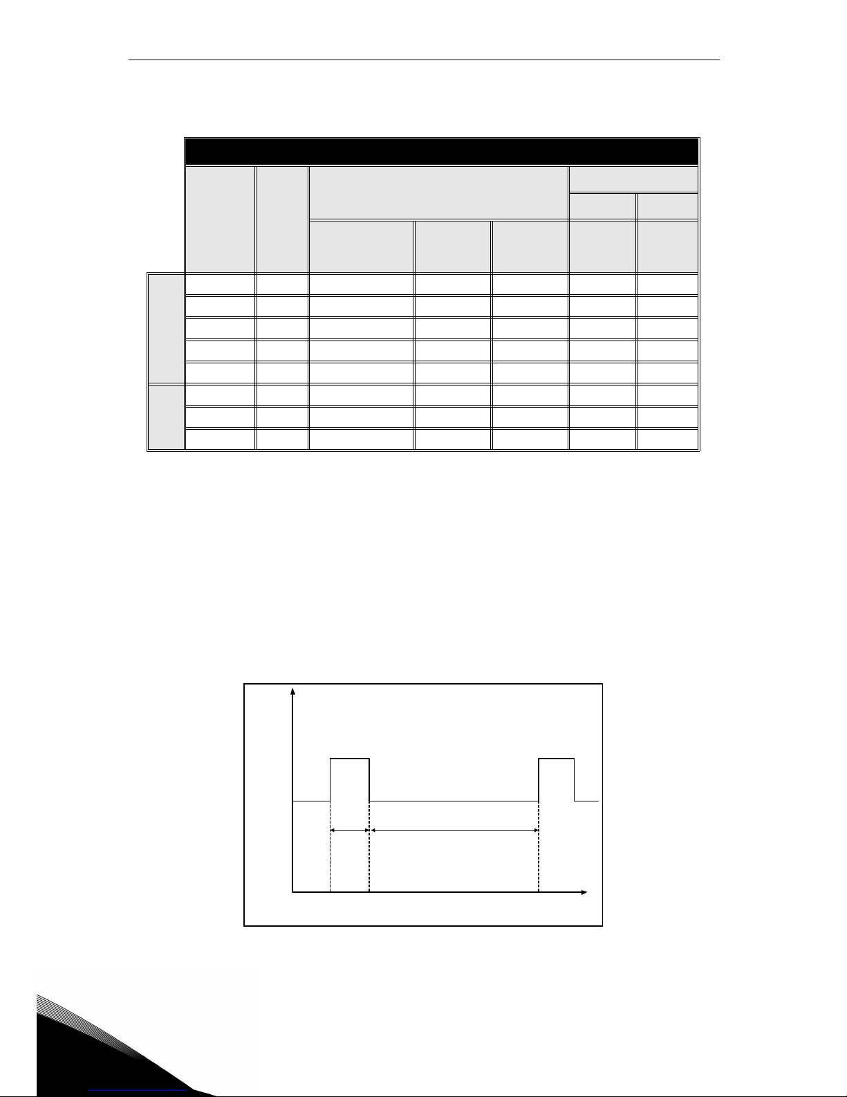
7
vacon • 71 Technical data
7.1.3 Mains voltage 3AC 380-480V
NOTE: The rated currents in given ambient temperatures (in Table 32) are achieved only when
the switching frequency is equal to or less than the factory default.
7.1.4 Definitions of overloadability
Overloadability =Following continuous operation at rated output current IN, the converter supplies
150% * I
N
for 1 min, followed by a period of at least 9 min at IN or below.
Example: If the duty cycle requires 150% rated current for 1 min in every 10 min, the remaining 9
min must be at rated current I
N
or less.
Figure 39. High overload.
Mains Voltage 3AC 380-480V, 50/60 Hz
Converter
type
Input
current
[A]
Loadability
Motor shaft power
400V 480V
Rated continuous
current I
N
[A]
50% overload
current
[A]
Max current
I
S
[kW] [HP]
MS2
0003 3.2 2.4 3.6 4.8 0.75 1.0
0004 4.0 3.3 5.0 6.6 1.1 1.5
0005 5.6 4.3 6.5 8.6 1.5 2.0
0006 7.3 5.6 8.4 11.2 2.2 3.0
0008 9.6 7.6 11.4 15.2 3.0 4.0
MS3
0009 11.5 9.0 13.5 18.0 4.0 5.0
0012 14.9 12.0 18.0 24.0 5.5 7.5
0016 20 16.0 24.0 32.0 7.5 10.0
Table 32. Power ratings of VACON® 20 CP, supply voltage 3AC 380-480V.
I
N
I
N*150%
1 min 9 min
I
N*150%
Current
Time
Page 75
Technical data vacon • 72
Service support: find your nearest Vacon service center at www.vacon.com
7
7.2 Brake resistors
Make sure that the resistance is higher than the minimum resistance defined. The power handling capacity must be sufficient for the application. Brake chopper is available only in threephase version.
Recommended brake resistor values for Vacon 20 CP AC drives:
Mains Voltage 3AC 208-240 V, 50/60 Hz
Frame Type
Minimum Resistance
recommended [Ohm]
MS2
0004 50
0005 50
0007 50
MS3
0011 25
0012 25
0017 25
Table 33. Brake resistor ratings, 3AC 208-240V.
Mains Voltage 3AC 380-480 V, 50/60 Hz
Frame Type
Minimum Resistance
recommended [Ohm]
MS2
0003 100
0004 100
0005 100
0006 100
0008 100
MS3
0009 50
0012 50
0016 50
Table 34. Brake resistor ratings, 3AC 380-480V.
Page 76
7
vacon • 73 Technical data
7.3 VACON® 20 CP - technical data
Mains connection
Input voltage U
in
3AC 208…240V
1AC 208…240V
3AC 380…480V
Input voltage tolerance -15%…+10% continuously
Input frequency 50/60 Hz
Input frequency
tolerance
45…66 Hz
Protection class I
Connection to mains Once per minute or less
Starting delay 4 s
Supply network
IT and TN-networks (cannot be used with cor-
ner earthed networks)
Short-circuit current Maximum short-circuit current has to be <50kA
DC connection
Available as standard in MS2 single-phase
frames and MS3
Motor connection
Output voltage
0…U
in
Rated output current
IN: Enclosure temperature max. +70°C.
See Table 30 , Table 31 and Table 32.
Overload output cur-
rent
1.5 x IN (1 min/10 min)
Starting current
IS for 2 s every 20 s (IS = 2.0 * IN)
Output frequency 0…320 Hz
Frequency resolution 0.01 Hz
Protection class I
Motor characteristics
AC squirrel cage motors
Permanent magnet motors
Cable type Screened motor cable
Cable maximum length 30 m
Control
characteristics
Switching frequency
Programmable 2…16 kHz;
Default 6 kHz.
Automatic switching frequency derating in case
of overheating
Frequency reference:
Analogue input
Panel reference
Resolution ±0.05% (11-bit), accuracy ±1%
Resolution 0.01 Hz
Field weakening point 8…320 Hz
Acceleration time 0.1…3000 sec
Deceleration time 0.1…3000 sec
Braking
Brake chopper standard in all three-phase
frames. External brake resistor optional.
Control
connections
See Chapter 5.
Page 77
Technical data vacon • 74
Service support: find your nearest Vacon service center at www.vacon.com
7
Communication
interface
Fieldbus
Standard: Serial communication (RS485/Mod-
bus);
Optional: CANopen; Profibus DP, Lonworks,
DeviceNet, Profinet IO, Ethernet IP, Modbus
TCP, EtherCAT, AS-interface
Status indicators
Drive status indicators (LED) on front side
(POWER, RUN, FAULT, READY)
Ambient conditions
Enclosure operating
temperature
-10°C (no frost)…+70°C
Storage temperature -40°C…+85°C
Relative humidity
0 to 95% RH, non-condensing, non-corrosive,
no dripping water
Pollution degree PD2
Altitude
100% load capacity (no derating) up to 1,000m;
derating 1% / 100m at 1,000...3,000m
Degree of protection
MS2 (three-phase version): IP00
MS2 (single-phase version): IP20
MS3: IP20
Stationary vibration:
Sinusoidal
MS2 (three-phase version):
3 Hz ≤ f ≤ 9Hz: 10mm
9 Hz ≤ f ≤ 200Hz: 3g
[3M7 acc. to IEC 60721-3-3]
MS2 (single-phase version) and MS3:
3 Hz ≤ f ≤ 8,43 Hz: 7,5 mm
8,43 Hz ≤ f ≤ 200 Hz: 2g
[3M6 acc. to IEC 60721-3-3]
Shock/Bump:
MS2 (three-phase version):
25g / 6 ms
[3M7 acc. to IEC 60721-3-3]
MS2 (single-phase version) and MS3:
25g / 6 ms
[3M6 acc. to IEC 60721-3-3]
Directives
EMC 2004/108/EC
Low Voltage 2006/95/EC
RoHS 2002/95/EC
WEEE 2012/19/EC
Page 78
7
vacon • 75 Technical data
Table 35. VACON® 20 Cold Plate technical data.
Standards
Immunity
EN61800-3: 2004 + A1: 2011, 1st and 2nd envi-
ronment
Emissions
EN61800-3: 2004 + A1: 2011,
3-phase version
Category C2 as standard for
conducted and radiated
emissions
1-phase version
Category C1 as standard for
conducted emissions
Category C2 as standard for
radiated emissions. It can be
C1 with a suitable enclosure
and cabling.
The drive can be modified to category C4.
Safety EN 61800-5-1
Production quality ISO 9001
Approvals
Functional Safety TÜV - Tested
Electrical Safety TÜV - Tested
EMC TÜV - Tested
USA, Canada cURus approval, file number E171278
Declaration of
Conformity
Korea KC mark
Australia C-tick Declaration of Conformity
Europe EC Declaration of Conformity
Protections
Undervoltage trip limit
Depends on supply voltage (0,8775*supply volt-
age):
Supply voltage 400 V: Trip limit 351 V
Supply voltage 480 V: Trip limit 421 V
Supply voltage 240 V: Trip limit 211 V
Earth fault protection Ye s
Mains supervision Yes
Motor phase supervision Yes (not available in 1-phase version)
Overcurrent protection Yes
Unit overtemperature
protection
Yes
Motor overload protection
Yes
Motor stall protection Yes
Motor underload
protection
Yes
Short-circuit protection of +24V and +10V
reference voltages
Yes
Thermal motor protection
Yes (by PTC with option card)
Page 79
Technical data vacon • 76
Service support: find your nearest Vacon service center at www.vacon.com
7
7.3.1 Technical information on control connections
Table 36. Technical information on standard I/O terminals.
Standard I/O terminals
Terminal Signal Technical information
A RS485
Differential receiver/transmitter
Set bus termination with dip switches (see Chapter 5)
B RS485
1 Reference output +10V, ±5%; Maximum current 10 mA
2
Analogue input,
voltage or current
Analogue input channel 1
0- +10V (Ri = 200 k
Ω)
0/4-20 mA (Ri =250 Ω)
Resolution 0.05 %, accuracy ±1 %
Selection V/mA with dip-switches (see Chapter 5).
Default 0- +10V
3
I/O ground
Ground for reference and controls (connected internally to
frame earth through 2M
Ω)
6
24V aux. voltage
+24V, ±10%, max volt. ripple < 100mVrms; max. 100 mA
Short-circuit protected
Can be used with an external power supply (with a current
limiter or fuse protected) to supply the control unit and
fieldbus for backup purposes.
Dimensioning: max. 1000mA/control unit.
7
DIN COM
Common for digital inputs. Connected to GND with dipswitch SW1. See Chapter 5
8
Digital input 1
Positive or negative logic
Ri = min. 4k
Ω
15…30V = "1"
0...5V = “0”
9
Digital input 2
10
Digital input 3
4
Analogue input,
voltage or current
Analogue input channel 2
0- +10V (Ri = 200 k
Ω)
0/4-20 mA (Ri =250 Ω)
Resolution 0.05%, accuracy ±1 %
Selection V/mA with dip-switches (see Chapter 5).
Default 0/4-20 mA
5
I/O ground
Ground for reference and controls (connected internally to
frame earth through 2M
Ω)
13
Digital output common
Common for digital output 1 (DO1-)
14
Digital input 4
Positive or negative logic
Ri = min. 4k
Ω
15…30V = "1"
0...5V = “0”
15
Digital input 5
16
Digital input 6
18
Analogue signal
(+output)
Analogue output channel 1,
0-10V (30mA max)
Resolution 0.1%, accuracy ±2,5 %
Short-circuited protected.
20
Digital Output 1 Open Collector max 35V / 50mA (DO1+)
Page 80
7
vacon • 77 Technical data
Table 37. Technical information on relays.
Relay terminals
Terminal Signal Technical information
22
Relay output 1
*
*
If 230VAC is used as control voltage from the output relays, the control circuitry
must be powered with a separate isolation transformer to limit short circuit current
and overvoltage spikes. This is to prevent welding on the relay contacts. Refer to
standard EN 60204-1, section 7.2.9
Switching capacity 250VAC/3A
(only earthed network allowed)
23
24
Relay output 2*
Switching capacity NO 250VAC/5A
NC 250VAC/3A
(only earthed network allowed)
25
26
Page 81
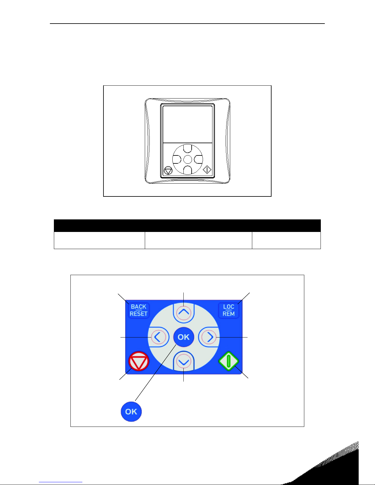
Options vacon • 78
Service support: find your nearest Vacon service center at www.vacon.com
8
8. OPTIONS
8.1 Vacon keypad with seven-segment display
The text keypad is an option available for VACON® 20 CP. The control keypad is the interface between the VACON
®
20 CP frequency converter and the user.
Figure 40. Text keypad.
With the keypad it’s possible to control the speed of the motor, to supervise the state of the drive
and to set the frequency converter’s parameters. The button section of the text keypad is shown in
the following picture.
Figure 41.Keypad buttons.
Order code Description Type of option
VACON-PAN-HMTX-MC06-CP
Handheld/Magnetic fixing IP66 text
keypad w/ cable, l=1m/39,37 inches
Loose option
Scroll menu up
Increase value
Scroll menu down
Decrease value
Move cursor left Move cursor right
Move backward in menu
Exit edit mode
Reset faults with long press
Change control place
Stop button Start button
Enter active level/item
Confirm selection
Page 82
8
vacon • 79 Options
8.2 Text keypad
The keypad display indicates the status of the motor and the drive and any irregularities in motor or
drive functions. On the display, the user can see the information about
his present
location in the
menu structure and the item displayed.
Figure 42. Keypad display.
8.3 Menu structure
The data on the control keypad are arranged in menus. Use the Up and Down arrows to move between the menus. Enter the group/item by pressing the OK button and
return
to the former level by
pressing the Back/Reset button. The arrows on the left of the display show the active menu. In
Figure 42 the REF menu is active. The table below shows the structure of the main menu:
Reference (REF) Reference from Keypad
Monitor (MON) Monitoring values
Parameters (PAR) Application parameters
System/Fault
(SYS/FLT)
System Menu
Active fault
History fault
Table 38. Keypad menus.
Indicators:
Status
Indicators:
Alarm, Fault
Indicators:
Menus
Indicators:
Direction
Indicators:
Control place
READY RUN STOP ALARM FAULT
FWD REV I/O KEYPAD BUS
REF
MON
PAR
SYS/FLT
.
Hz
Page 83
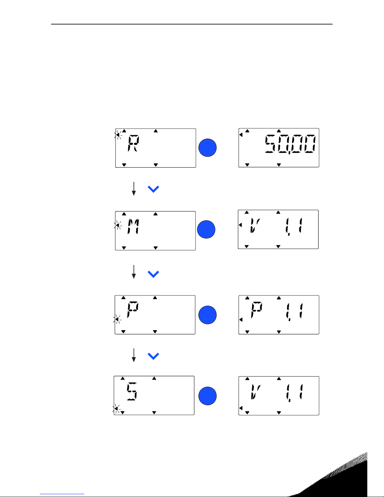
Options vacon • 80
Service support: find your nearest Vacon service center at www.vacon.com
8
8.4 Using the keypad
This chapter provides you with information on navigating the menus on Vacon 20 CP and
editing the values of the parameters.
8.4.1 Main menu
The menu structure of Vacon 20 CP control software consists of a main menu and several
submenus. Navigation in the main menu is shown below:
Figure 43. The Main menu of Vacon 20 CP.
FWD R EV I/O K EYPAD BUS
REF
MON
PA R
FAU LTALARMSTOPREADY RUN
FWD REV I/O KEYPAD BU S
REF
PA R
FAU LTALARMSTOPREADY RUN
MON
FW D R EV I/O KEY PAD BU S
REF
PAR
FAU L TALARMSTO PREADY RUN
MON
FWD REV I/O KEYPAD BUS
EF
PAR
FAULTALARMSTOPREADY RUN
MON
FWD REV I/O KEYPAD BUS
REF
PAR
FAULTALARMSTOPREADY RUN
MON
FWD REV I/O KEYPAD BUS
REF
PAR
FAULTALARMSTOPREADY RUN
MON
FWD REV I/O KEYPAD BUS
REF
PAR
FAU LTALARMSTO PREAD Y RU N
MON
PRESS
PRESS
PRESS
PRESS
PRESS
FWD REV I/O KEYPAD BUS
REF
MON
PA R
FAULTALARMSTOPREAD Y R UN
PRESS
PRESS
OK
OK
OK
OK
OK
In this menu
you can
browse the
monitoring
values.
In this menu
you can
browse and
edit the
parameters.
Dispalys the
keypad referen ce
value
regardless of
the sele cted
contron pla ce .
r
Here you will be
able to browse
system paramete
and fault
submenu.
Hz
Hz
FLTSYS /
FLTSYS /
FLTSYS /
FLTSYS /
FLTSYS /
FLTSYS /
FLTSYS /
FLTSYS /
FLTSYS /
SYSTEM/FAULT
MENU
PA R A MET ER
MEN U
MONI TOR
MEN U
REFERENCE
MEN U
Page 84

8
vacon • 81 Options
8.4.2 Resetting fault
When a fault appears and the drive stops examine the cause of the fault, perform the action advised
in the Fault Tracing paragraph and reset the fault by pressing the RESET button.
8.4.3 Local/Remote control button
The LOC/REM button is used for two functions: to quickly access the Control page and to easily
change between the Local (Keypad) and Remote control places.
Control places
The
control place is the source of control where the drive can be started and stopped. Every control
place has its own parameter for selecting the frequency reference source. In the VACON
®
20 CP
drive, the
Local control place is always the keypad. The Remote control place is determined by pa-
rameter (I/O or Fieldbus). The selected control place can be seen on the status bar of the keypad.
Remote control place
I/O and Fieldbus can be used as remote control places.
Local control
Keypad is always used as control place while in local control. Local control has higher priority than
remote control. Switching between Local and Remote Control can be done by pressing the LOC/
REM-button on the keypad.
Page 85
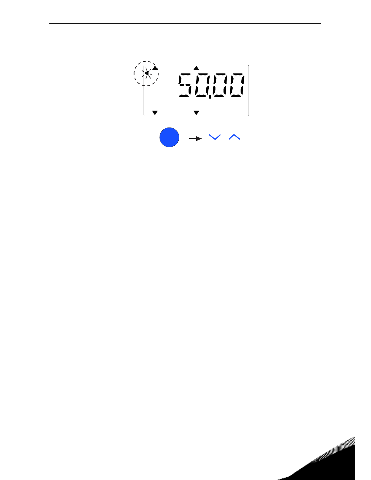
Options vacon • 82
Service support: find your nearest Vacon service center at www.vacon.com
8
8.4.4 Reference menu
Figure 44. Reference menu.
Move to the reference menu with the UP / DOWN button (see Figure 43). The reference
value can be changed with UP / DOWN button as shown in Figure 44.
If the value has big change, first press Left and Right buttons to select the digit which has to be
changed, then press Up button to increase and Down button to decreases the value in the selected
digit. The changing reference frequency will been taken into use immediately without pressing OK.
Note! LEFT and RIGHT buttons can be used to change the direction in Ref menu in local control
mode.
Press to enter
edit mode
Change
value
OK
FWD REV I/O KEYPAD BUS
REF
MON
PA R
FAULTALARMSTOPRE ADY R UN
Hz
FLTSYS /
Page 86
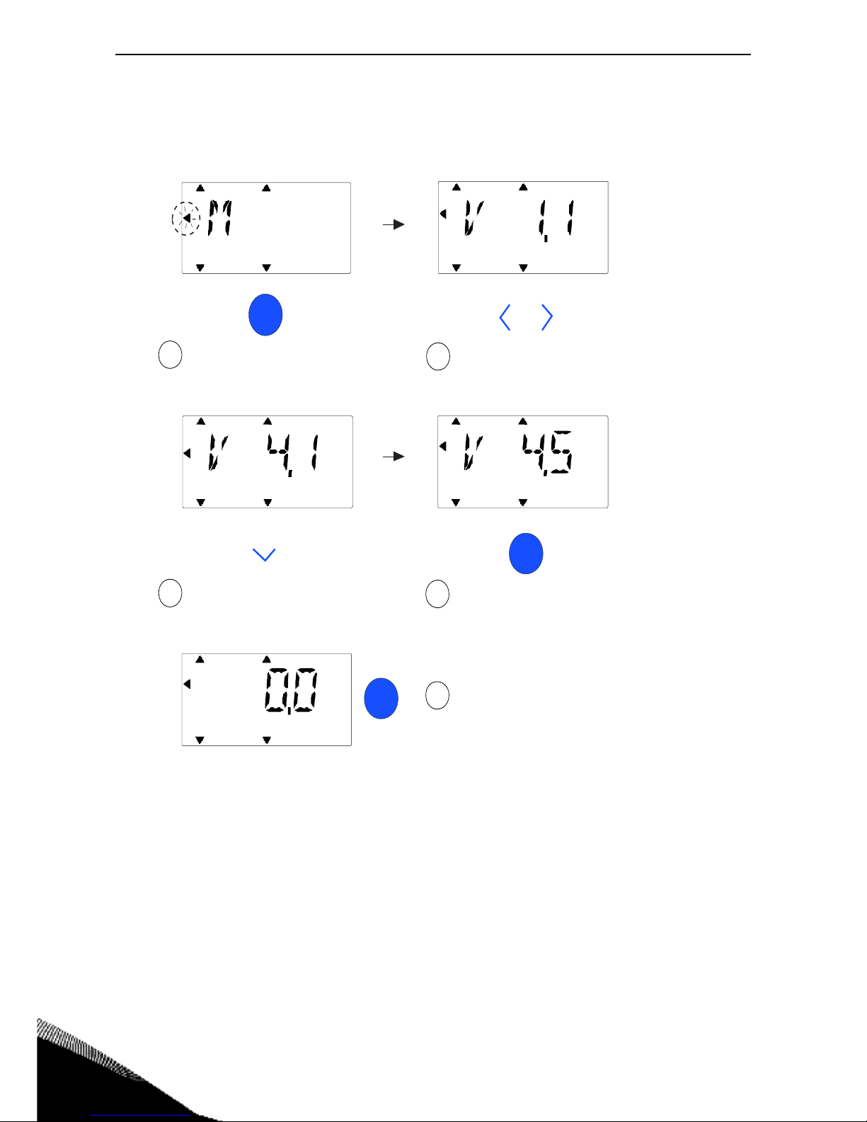
8
vacon • 83 Options
8.4.5 Monitoring menu
Monitoring values are actual values of measured signals as well as status of some control settings.
It is visible in Vacon 20 CP display, but it can not be edited. The monitoring values are listed in the
Application Manual.
Figure 45. Monitoring menu.
Pressing Left/Right button to change the actual parameter to the first parameter of the next group,
to browse monitor menu from V1.x to V2.1 to V3.1 to V4.1. After entering the desired group, the monitoring values can be browsed by pressing UP/DOWN button, as shown in Figure 45. In MON menu
the selected signal and its value are alternating in the display by pressing OK button.
Note! Turn on drive power, arrowhead of main menu is at MON, V x.x or monitor parameter value
of Vx.x is displayed in Panel. Display Vx.x or monitor parameter value of Vx.x is determined by the
last show status before power shut down.
OK
OK
OK
1
2
3
5
4
FAULTALARMSTOPRE ADY RU N
REF
MON
PA R
REF
MON
PA R
FAULTALARMSTOPRE ADY R U N
FWD REV I/O K EYPAD BUS FWD REV I/O K EYPAD BUS
REF
MON
PA R
FAULTALARMSTOPREADY RU N
FWD R EV I/O KEYPAD BUS
REF
MON
PA R
FAU LTALARMSTOPRE ADY RU N
FWD REV I/O K EYPAD BUS
FAU LTALARMSTOPRE ADY RU N
REF
MON
PA R
FWD REV I/O K EYPAD BUS
FLTSYS /
FLTSYS /
FLTSYS /
FLTSYS /
FLTSYS /
Press OK to enter
Monitoring menu
Press Left/Right to browse
other Monitoring groups
Press Down to
browse V4.5
Press OK to select
V4.5
Press OK to display
the value
Page 87
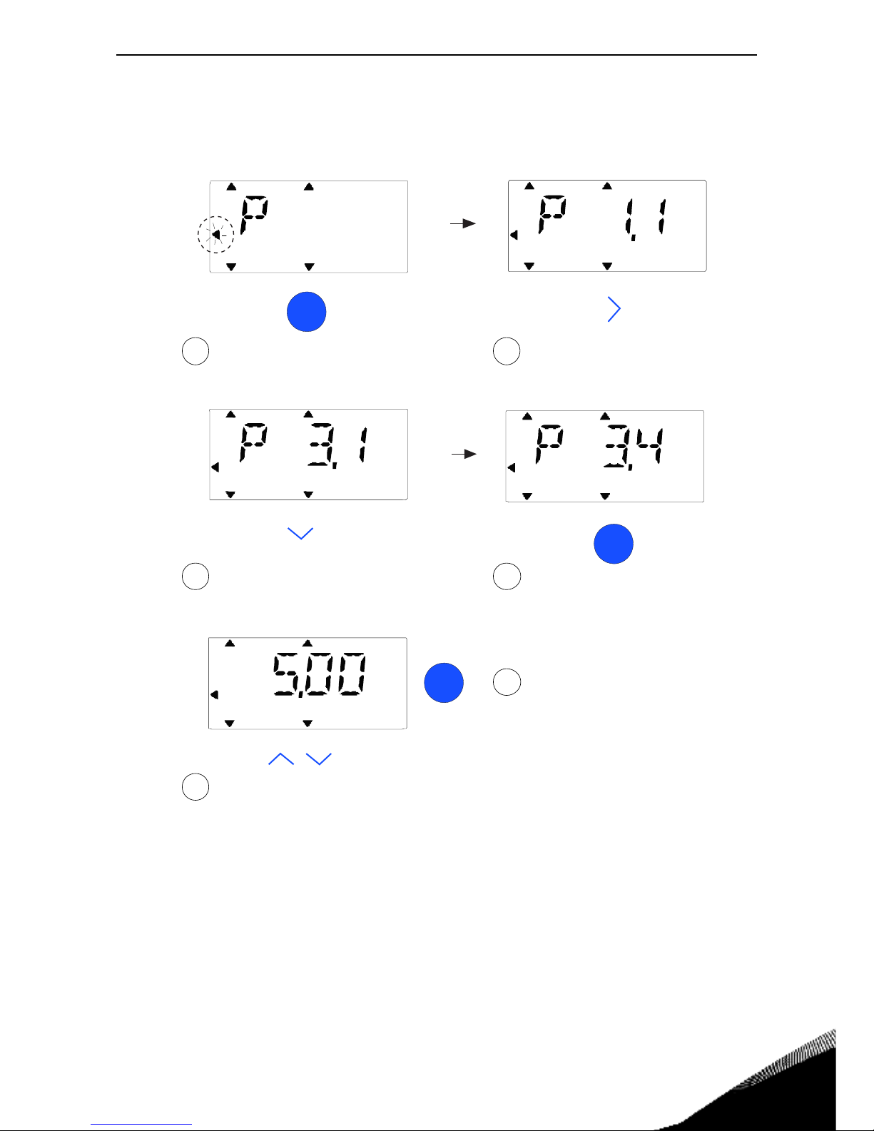
Options vacon • 84
Service support: find your nearest Vacon service center at www.vacon.com
8
8.4.6 Parameter menu
In Parameter menu only the Quick setup parameter list is shown as default. To view the other advanced parameter groups, see the Application Manual. The following figure shows the parameter
menu view:
Figure 46.Parameter menu
Change value of a parameter following the procedure below:
1. Locate the parameter.
2. Enter the Edit mode by pressing OK.
3. Set new value with the arrow buttons up/down. You can also move from digit to digit with the
arrow buttons left/right if the value is numerical and change then the value with the arrow buttons up/down.
4. Confirm change with OK button or ignore change by returning to previous level with Back/
Reset button.
OK
OK
2
Press Right to browse
other Par. group
4
Press OK button to enter
edit mode
3
Press down button to
browse P3.4
5
Press Up / Down to change value
OK
6
Press OK to confirm
FA ULTALARMSTOPREADY RU N FAU LTALARMSTOPREADY RU N
FA ULTALARMSTOPRE ADY RU N
FWD REV I/OKEYPAD BUS FWD REV I/OKEYPAD BUS
FWD R EV I/O K EY PAD BUS
1
Press OK to enter Pa r. menu
FAU LTALARMSTOPRE ADY RU N
FWD R EV I/O K EYPAD BUS
FA ULTALARMSTOPREADY RU N
FWD REV I/O K EYPAD BUS
Hz
SYS / FLT
PAR
REF
MON
SYS / FLT
PAR
REF
MON
SYS / FLT
PAR
REF
MON
SYS / FLT
PAR
REF
MON
SYS / FLT
PAR
REF
MON
Page 88
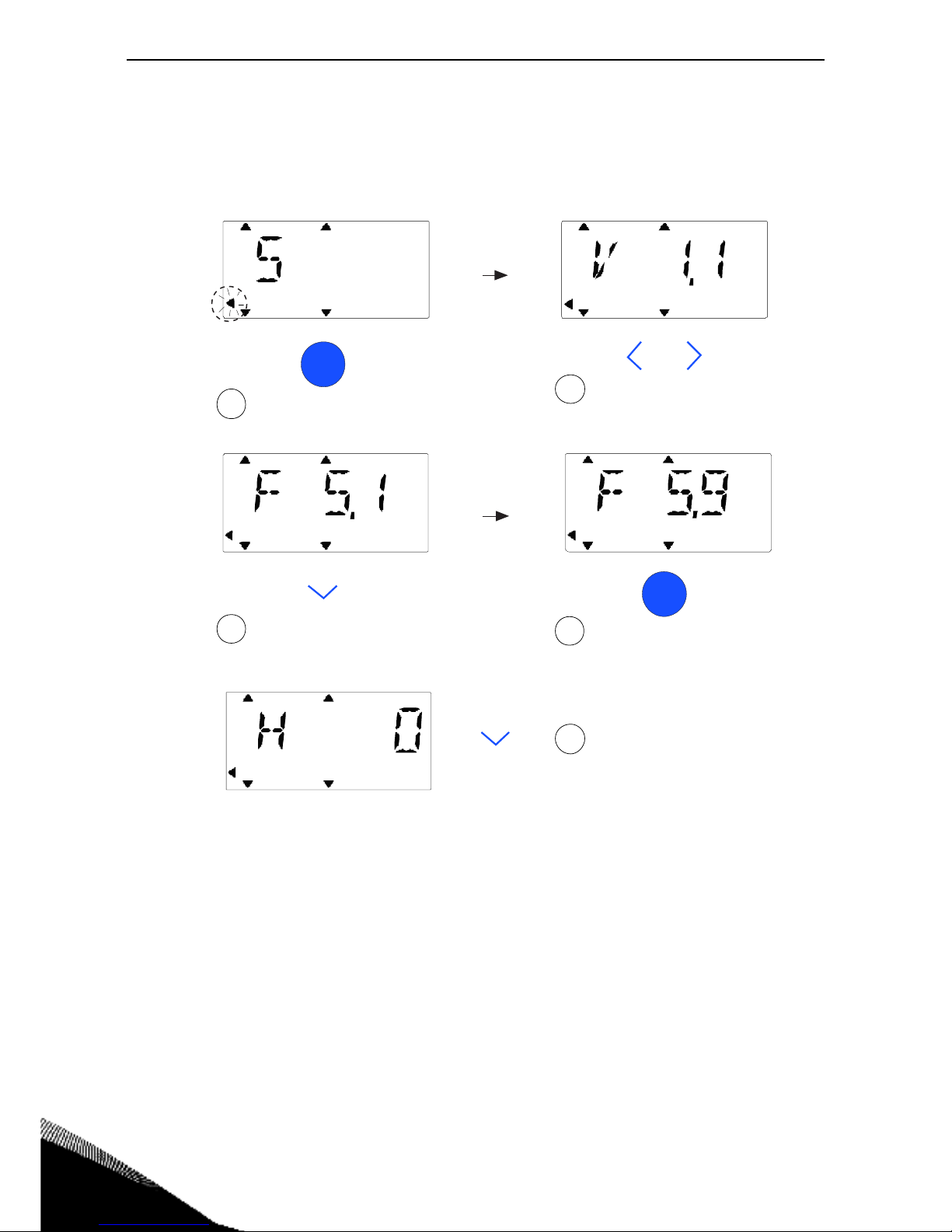
8
vacon • 85 Options
8.4.7 System/Fault menu
SYS/FLT menu including fault submenu, field bus submenu and system parameter submenu. In
system parameter submenu, there are some editable parameter (P) and some not editable parameters (V). The Fault submenu of SYS/FLT menu includes active fault submenu and fault history submenu.
Figure 47. System and Fault menu.
OK
Press OK to enter V1.1
1
Press Left/Right button
to browse other groups
2
Pressdowntobrowse
other active faults
3
FAU LTALARMSTOP
FWD R EV I/O K EYPAD BUS
READY RU N
OK
Press OK to select one fault
to browse its time
4
FAU LTALA RMSTOPREADY RUN
FWD REV I/O KEYPAD BUS
Browse for fault code(C xx),
subcode(Id xx), days(d xx),
hours(H xx), minutes(M xx)
5
FAU LTALARMSTOPREADY RUN
FWD REV I/O KEYPAD BUS
FAU LTALA RMSTOPREAD Y RU N
FWD REV I/O KEYPAD BUS
FAU LTALA RMSTOPREADY RUN
FWD REV I/O KEYPAD BUS
SYS / FLT
PA R
REF
MON
SYS / FLT
PA R
REF
MON
SYS / FLT
PA R
REF
MON
SYS / FLT
PA R
REF
MON
SYS / FLT
PA R
REF
MON
Page 89
Options vacon • 86
Service support: find your nearest Vacon service center at www.vacon.com
8
8.4.7.1 Faults
Under this menu, you can find Active faults, Reset faults, Fault history, Counters and Software in-
fo.
In active fault situation, FAULT arrow is blinking and the display is blinking active fault menu item
with fault code. If there are several active faults, you can check it by entering the active fault submenu F5.x. F5.1 is always the latest active fault code. The active faults can be reset by pressing
BACK / RESET button with long time (>2 s), when the API is in active fault submenu level (F5.x). If
the fault cannot be reset, the blinking continues. It is possible to select other display menus during
active fault, but in this case the display returns automatically to the fault menu if no button is
pressed in 10 seconds. The fault code, subcode and the operating day, hour and minute values at
the fault instant are shown in the value menu (operating hours = displayed reading).
Active faults
Fault history
Menu Function Note
Active faults When a fault/faults appear(s), the
display with the name of the fault
starts to blink. Press OK to return
to the Diagnostics menu. The
Active faults submenu shows the
number of faults. Select the fault
and push OK to see the fault-time
data.
The fault remains active until it is
cleared with the RESET button or
with a reset signal from the I/O terminal or fieldbus or by choosing
Re-
set faults
(see below).
The memory of active faults can
store the maximum of 10 faults in
the order of appearance.
Menu Function Note
Fault history 10 latest faults are stored in the
Fault history.
Entering the Fault history and clicking OK on the selected fault shows
the fault time data (details).
Page 90
8
vacon • 87 Options
8.5 Fault tracing
Fault
code
Fault name Subcode Possible cause Remedy
1
Overcurrent
AC drive has detected too high a
current (>4*I
H
) in the motor cable:
• sudden heavy load increase
• short circuit in motor cables
• unsuitable motor
Check loading.
Check motor.
Check cables and connections.
Make identification run.
Check ramp times.
2
Overvoltage
The DC-link voltage has exceeded
the limits defined.
• too short a deceleration
time
• brake chopper is disabled
• high overvoltage spikes in
supply
• Start/Stop sequence too fast
Make deceleration time longer.
Use brake chopper or brake resistor
(available as options).
Activate overvoltage controller.
Check input voltage.
3
Earth fault
Current measurement has
detected that the sum of motor
phase current is not zero.
• insulation failure in cables
or motor
Check motor cables and motor.
84 MPI communication crc error
Reset the fault and restart.
Should the fault re-occur, contact the
distributor near to you.
89 HMI receives buffer overflow
Check PC-drive cable.
Try to reduce ambient noise
90 Modbus receives buffer overflow
Check Modbus specifications for
time-out.
Check cable length.
Reduce ambient noise.
Check baudrate.
8
System Fault 93 Power identification error
Try to reduce ambient noise.
Reset the fault and restart.
Should the fault re-occur, contact the
distributor near to you.
97 MPI off line error
Reset the fault and restart.
Should the fault re-occur, contact the
distributor near to you.
98 MPI driver error
Reset the fault and restart.
Should the fault re-occur, contact the
distributor near to you.
99 Option board driver error
Check contact in option board slot
Try to reduce ambient noise;
Reset the fault and restart.
Should the fault re-occur, contact the
distributor near to you.
100 Option board configuration error
Check contact in option board slot
Try to reduce ambient noise;
Should the fault re-occur, contact the
distributor near to you.
Table 39. Fault codes and descriptions.
Page 91
Options vacon • 88
Service support: find your nearest Vacon service center at www.vacon.com
8
101 Modbus buffer overflow
Check Modbus specifications for
time-out.
Check cable length.
Reduce ambient noise.
Check baudrate.
104 Option board channel full
Check contacts in option board slot.
Try to reduce ambient noise.
Should the fault re-occur, contact the
distributor near to you.
105
Option board memory allocation
fail
Check contacts in option board slot.
Try to reduce ambient noise.
Should the fault re-occur, contact the
distributor near to you.
106 Option board Object queue full
Check contacts in option board slot.
Try to reduce ambient noise.
Should the fault re-occur, contact the
distributor near to you.
8
System Fault 107 Option board HMI queue full
Check contacts in option board slot.
Try to reduce ambient noise.
Should the fault re-occur, contact the
distributor near to you.
108 Option board SPI queue full
Check contacts in option board slot.
Try to reduce ambient noise.
Should the fault re-occur, contact the
distributor near to you.
111 Parameter copy error
Check if parameter set is compatible
with drive.
Do not remove Keypad until copy is
finished.
113
Frequency detective timer overflow
Check keypad contacts.
Try to reduce ambient noise.
Should the fault re-occur, contact the
distributor near to you.
114 PC control time out fault
Do not close Vacon Live when PC
control is active.
Check PC-Drive cable.
Try to reduce ambient noise.
115 DeviceProperty data format
Reset the fault and restart.
Should the fault re-occur, contact the
distributor near to you.
120 Task stack overflow
Reset the fault and restart.
Should the fault re-occur, contact the
distributor near to you.
Fault
code
Fault name Subcode Possible cause Remedy
Table 39. Fault codes and descriptions.
Page 92

8
vacon • 89 Options
9
Undervoltage
DC-link voltage is under the voltage limits defined.
• most probable cause: too
low a supply voltage
• AC drive internal fault
• defect input fuse
• external charge switch not
closed
NOTE! This fault is activated only
if the drive is in Run state.
In case of temporary supply voltage
break reset the fault and restart the
AC drive. Check the supply voltage. If
it is adequate, an internal failure has
occurred.
Contact the distributor near to you.
10
Input phase Input line phase is missing.
Check supply voltage, fuses and
cable.
11
Output phase
Current measurement has
detected that there is no current in
one motor phase.
Check motor cables and motor.
13
AC drive
undertemperature
Too low temperature measured in
power unit’s heatsink or board.
Heatsink temperature is under 10°C.
Check the ambient temperature.
14
AC drive
overtemperature
Too high temperature measured in
power unit’s heatsink or board.
Heatsink temperature is over
100°C.
Check the correct amount and flow of
cooling air.
Check the heatsink for dust.
Check the ambient temperature.
Make sure that the switching frequency is not too high in relation to
ambient temperature and motor
load.
15
Motor stalled Motor is stalled.
Check motor and load.
Insufficient motor power, check
motor stall protection parametrization.
16
Motor
overtemperature
Motor is overloaded.
Decrease motor load.
If no motor overload exists, check the
temperature model parameters.
17
Motor underload Motor is under loaded
Check load. Check underload protection parametrization.
19
Power overload Supervision for drive power Drive power is to high: decrease load.
25
Watchdog
Error in the microprocessor monitoring
Malfunction
Component fault
Reset the fault and restart.
If the fault occurs again, please contact your closest Vacon representative.
27
Back EMF
Protection of unit when starting
with rotating motor
Reset the fault and restart.
Should the fault re-occur, contact the
distributor near to you.
30
STO fault
Safe torque off signal does not
allow drive to be set as ready
Reset the fault and restart.
Should the fault re-occur, contact the
distributor near to you.
Fault
code
Fault name Subcode Possible cause Remedy
Table 39. Fault codes and descriptions.
Page 93
Options vacon • 90
Service support: find your nearest Vacon service center at www.vacon.com
8
35
Application
error
0
Firmware Interface version
between Application and Control
not matching
Load a compatible application.
Please contact your closest Vacon
representative.
1 Application software flash error Reload Application
2 Application header error
Load a compatible application.
Please contact your closest Vacon
representative.
41
IGBT temp
IGBT temperature (UnitTemperature + I2T) too high
Check loading.
Check motor size.
Make identification run.
50
4 mA fault
(Analog input)
Selected signal range: 4...20 mA
(see Application Manual)
Current less than 4 mA
Signal line broken detached
The signal source is faulty
Check the analog input’s current
source and circuit.
51
External fault
Error message on digital input.
The digital input was programmed
as an input for external error messages. The input is active.
Check the programming and check
the device indicated by the error
message.
Check the cabling for the respective
device as well.
52
Keypad Communication
fault
The connection between the control keypad and the frequency converter is broken.
Check keypad connection and keypad
cable.
53
Fieldbus communication
fault
The data connection between the
fieldbus master and fieldbus board
is broken
Check installation and fieldbus master.
54
Fieldbus Interface error Defective option board or slot Check board and slot.
55
Wrong run command
Wrong run alarm and stop command
Run forward and backward are activated at the same time
56
Temperature Temperature fault
Board OPTBH is installed and measured temperature is above (or
below) the limit
57
Identification Identification alarm
Motor identification has not been
successfully completed
63
Quick Stop Quick Stop activated
The drive has been stopped with
Quick Stop digital input or Quick Stop
command by fieldbus
Fault
code
Fault name Subcode Possible cause Remedy
Table 39. Fault codes and descriptions.
Page 94
8
vacon • 91 Options
8.6 Option boards
VACON® 20 CP drive family embodies a wide selection of expander boards with which the available
I/O resources of VACON
®
20 CP frequency converter can be increased and its versatility improved.
There is one board slot (labelled D) on the VACON
®
20 CP control unit. To locate the slot, see Chapter 5. Usually, when the AC drive is delivered from the factory, the control unit doesn’t include any
option board in the board slot.
The following option boards are supported:
See the Option boards User’s Manual to use and install the option boards.
Order Code Description Note
OPT-B1-V
Option board with six bidirec-
tional terminals.
With jumper blocks it’s possible to
use each terminal as digital input or
as digital output.
OPT-B2-V
I/O expander board with a
thermistor input and two relay
outputs.
OPT-B4-V
I/O expander board with one
galvanically isolated analogue
input and two
galvanically isolated analogue
outputs (standard signals
0(4)…20mA).
OPT-B5-V
I/O expander board with three
relay outputs
OPT-B9-V
I/O expander board with five
42…240 VAC digital inputs and
one relay output.
OPT-BF-V
I/O expander board with ana-
logue output, digital output and
relay output.
On the OPTBF board, there is one
jumper block for selecting the ana-
logue output mode (mA/V).
OPT-BH-V
Temperature measurement
board with three individual
channels.
Supported sensors: PT100, PT1000,
NI1000, KTY84-130, KTY84-150,
KTY84-131
OPT-BK-V ASi option board AS-interface option card
OPT-C4-V Lonworks option board
Pluggable connector with screw ter-
minals
OPT-C3/E3-V Profibus DP option board
Pluggable connector with screw ter-
minals
OPT-C5/E5-V Profibus DP option board 9-pin Sub-D terminal
OPT-C6/E6-V CANopen option board
OPT-C7/E7-V DeviceNet option board
OPT-CI-V Modbus TCP option board
OPT-CP-V Profinet option board
OPT-CQ-V Ethernet IP option board
OPT-EC-V EtherCat option board
Table 40. Option boards supported in VACON® 20 CP.
Page 95
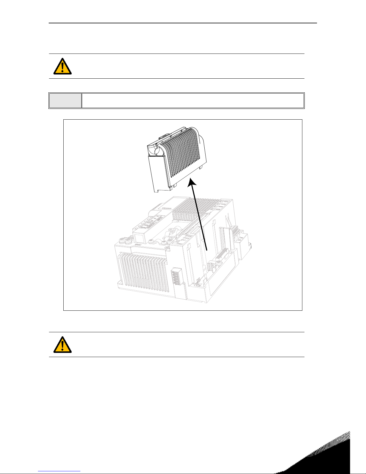
Options vacon • 92
Service support: find your nearest Vacon service center at www.vacon.com
8
8.6.1 Option board installation
Figure 48. Opening the main cover, MS2 three-phase version example.
NOTE! Do not add or replace option boards or fieldbus boards on an AC
drive with the power switched on. This may damage the boards.
1
• Remove the option slot cover.
The relay outputs and other I/O-terminals may have a dangerous control voltage
present even when the drive is disconnected from mains.
Page 96
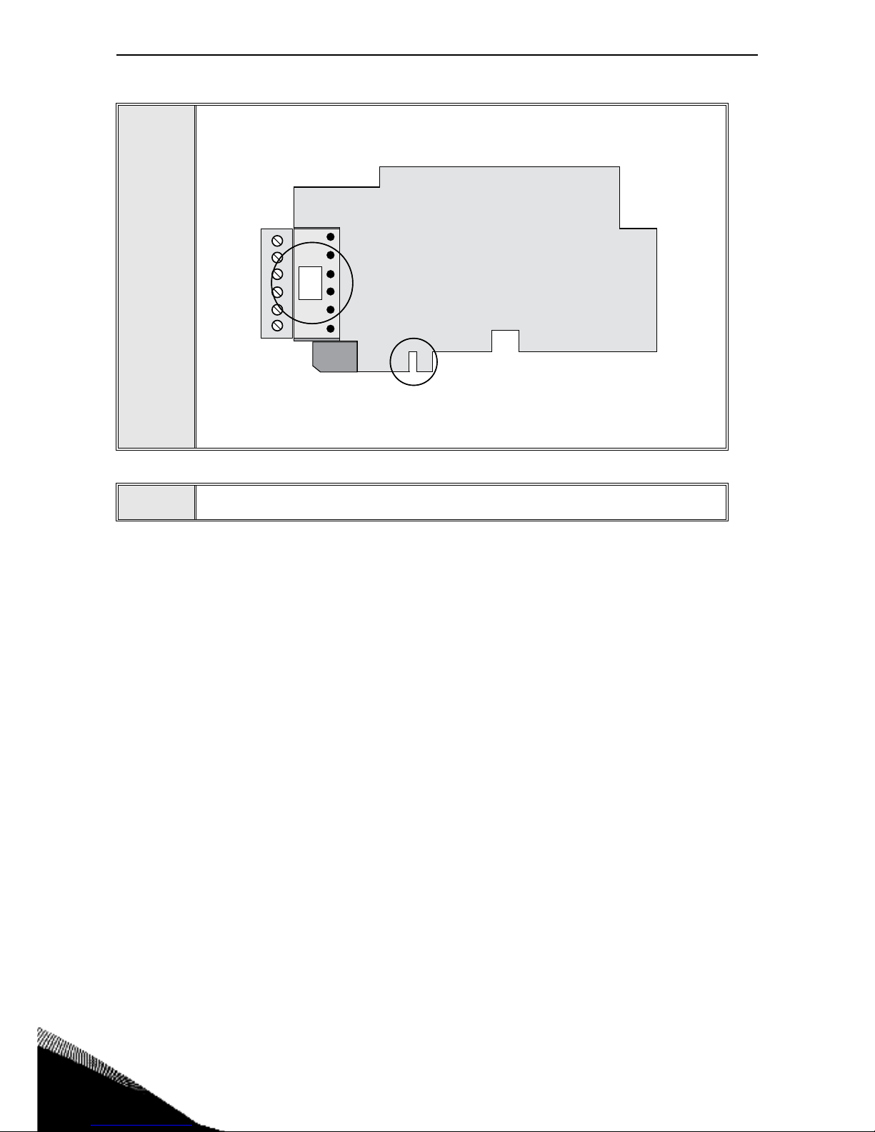
8
vacon • 93 Options
2
• Make sure that the sticker on the connector of the board says “dv” (dual
voltage). This indicates that the board is compatible with Vacon 20 CP. See
below:
• NOTE: Incompatible boards cannot be installed on Vacon 20 CP. Compatible boards have a slot coding that enables the placing of the board (see
above)
3
• Install the option board into the slot as shown in the picture below.
Slot coding
OPT
dv
9116.emf
Page 97
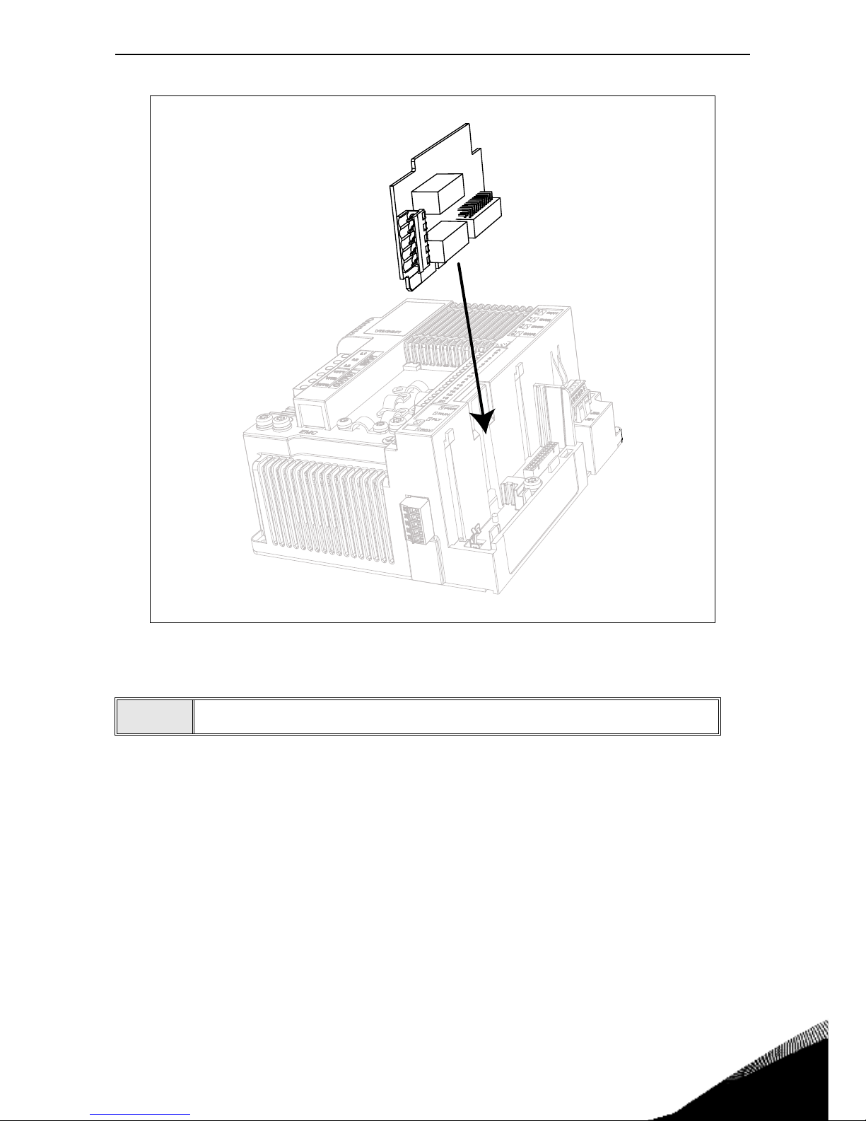
Options vacon • 94
Service support: find your nearest Vacon service center at www.vacon.com
8
Figure 49. Option board installation.
4
• Mount the option slot cover.
Page 98
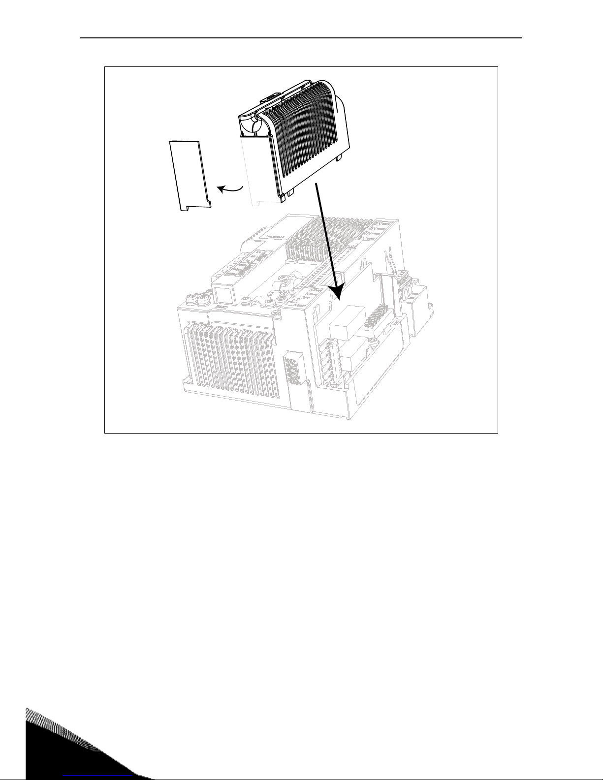
8
vacon • 95 Options
Figure 50. Mounting of the option slot cover: remove the plastic opening for the option board
terminals.
Page 99
Safe Torque Off vacon • 96
Service support: find your nearest Vacon service center at www.vacon.com
9
9. SAFE TORQUE OFF
This chapter describes the Safe Torque Off (STO) function which is a functional safety feature present in VACON
®
20 CP drive products as standard. This function is available only in the three-phase
version.
9.1 General description
The STO function brings the motor in no-torque-state as defined by 4.2.2.2 of the IEC 61800-5-2:
“Power that can cause rotation (or motion in the case of a linear motor) is not applied to the
motor. The Power Drive System (Safety Related) will not provide energy to the motor which can
generate torque (or force in the case of a linear motor).”
Therefore, the STO function is suitable for applications that rely on the immediate removal of power
to the actuator, resulting in an uncontrolled coast to stop (activated by an STO demand). Additional
protective measures need to be applied when an application requires a different stop method.
9.2 Warnings
Designing of safety-related systems requires specialist knowledge and skills. Only
qualified people are permitted to install and set up the STO function. The use of STO
does not itself ensure safety. An overall risk evaluation is required for ensuring that
the commissioned system is safe. Safety devices must be correctly incorporated into
the entire system which must be designed in compliance with all relevant standards
within the field of industry.
The information in this manual provides guidance on the use of the STO function. This
information is in compliance with accepted practice and regulations at the time of
writing. However, the end product/system designer is responsible for ensuring that
the end-system is safe and in compliance with relevant regulations.
When a permanent magnet motor is used and in case of a multiple IGBT power semiconductor failure, when the STO option energizes the drive outputs to the off state,
the drive system may still provide an alignment torque which maximally rotates the
motor shaft by 180°/p (where p is the number of poles of the motor) before the torque
production ceases.
Electronic means and contactors are not adequate for protection against electric
shock. The Safe Torque Off function does not disconnect the voltage or the mains
from the drive. Therefore hazardous voltages may still be present on the motor. If
electrical or maintenance work has to be carried out on electrical parts of the drive
or the motor, the drive has to be completely isolated from the main supply, e.g. using
an external supply disconnecting switch (see EN60204-1 section 5.3).
This safety function corresponds to an uncontrolled stop in accordance with stop category 0 of IEC 60204-1. The STO function does not comply with Emergency Switching
Off according to IEC 60204-1 (no galvanic insulation from the Mains in case the motor
is stopped).
The STO function is not a prevention of unexpected start-up. To fulfil those requirements, additional external components are required according to appropriate standards and application requirements.
In circumstances where external influences (e.g. falling of suspended loads) are
present additional measures (e.g. mechanical brakes) may be necessary to prevent
any hazard.
STO shall not be used as a control for starting or stopping the drive.
Page 100
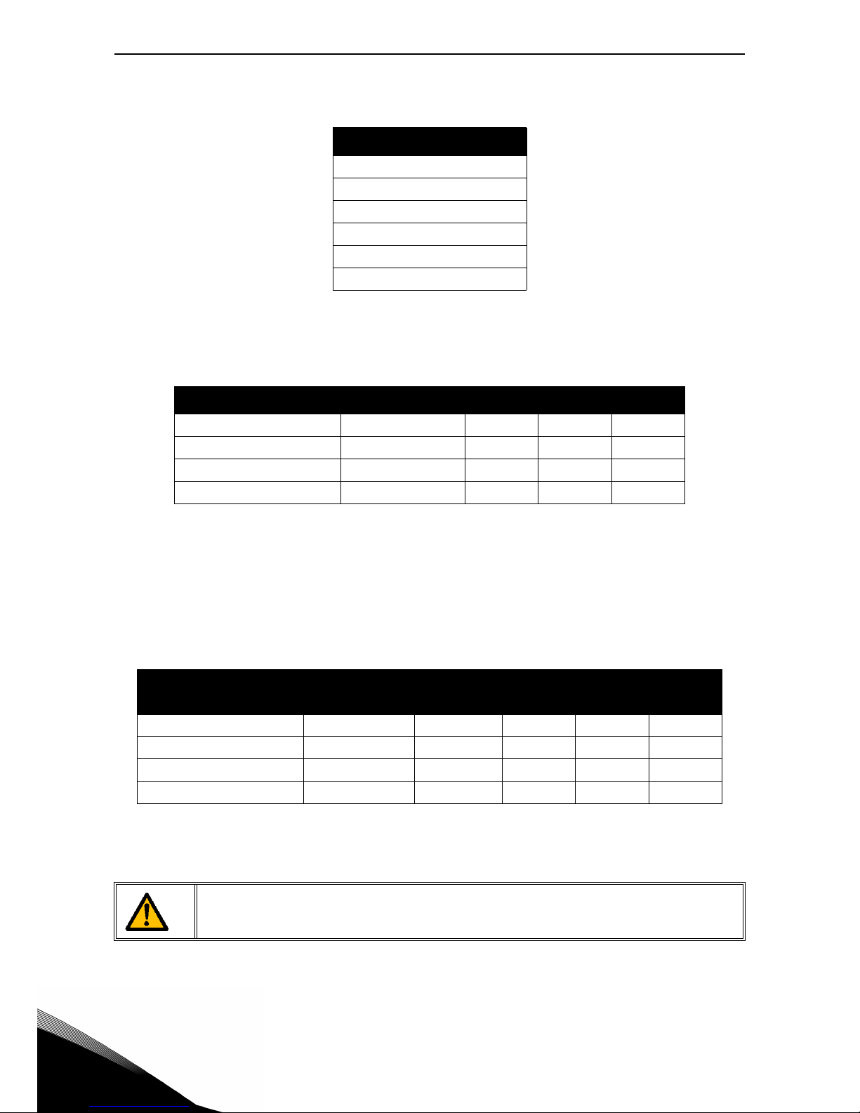
9
vacon • 97 Safe Torque Off
9.3 Standards
The STO function has been designed for use in accordance with the following standards:
The STO function has to be applied correctly to achieve the desired level of operational safety. Four
different levels are allowed, depending on the use of the STO signals (see the following table).
The same values are calculated for SIL and SIL CL. According to EN 60204-1, the emergency stop
category is 0.
The SIL value for the safety related system, operating in high demand/continuous mode, is related
to the probability of dangerous failure per hour (PFH), reported in the following table.
Standards
IEC 61508, Parts 1-7
EN 61800-5-2
EN 62061
ISO 13849-1
EN 954-1
IEC 60204-1
Table 41. Safety Standards.
STO inputs STO feedback Cat. PL SIL
Both dynamically used(*) Used 4 e 3
Both statically used Used 3 e 3
Connected in parallel Used 2 d 2
Connected in parallel Not used 1 c 1
Table 42. Four different STO levels. (*) see 9.5.1.
STO inputs STO feedback PFH PFDav
MTTFd
(years)
DCavg
Both dynamically used(*) Used 8.0 E-10 1/h 7.0 E-05 8314 y HIGH
Both statically used Used 8.1 E-10 1/h 7.1 E-05 8314 y MEDIUM
Connected in parallel Used 8.1 E-10 1/h 7.1 E-05 8314 y MEDIUM
Connected in parallel Not used 9.2 E-10 1/h 8.0 E-05 8314 y NONE
Table 43. SIL values. (*) see 9.5.1.
The STO inputs must always be supplied by a safety device.
The power supply of the safety device may be external or taken from the drive (as
long as this is compliant with the rating specified for terminal 6).
 Loading...