

Page 1

vacon 100
®
ac drives
application manual
Page 2

Page 3

PREFACE VACON · 3
PREFACE
Document ID: DPD00927F
Date: 30.1.2014
Software version: FW0072V012
ABOUT THIS MANUAL
This manual is copyright of Vacon Plc. All Rights Reserved.
In this manual, you can read about the functions of the Vacon® AC drive and how to use the
drive. The manual has the same structure than the menu of the drive (chapters 1 and 4-8).
Chapter 1, Quick Startup Guide
How to start the work with the control panel.
•
Chapter 2, Wizards
Making a selection of the application configuration.
•
Setting up an application quickly.
•
The different applications with examples.
•
Chapter 3, User Interfaces
The display types and how to use the control panel.
•
The PC tool Vacon Live.
•
The functions of the fieldbus.
•
Chapter 4, Monitoring menu
Data on the monitoring values.
•
Chapter 5, Parameter menu
A list of all the parameters of the drive.
•
Chapter 6, Diagnostics menu
Chapter 7, I/O and Hardware menu
Chapter 8, User settings, favourites and user level menus
Chapter 9, Parameter descriptions
How to use the parameters.
•
Digital and analogue input programming.
•
Application-specific functions.
•
24-HOUR SUPPORT +358 (0)201 212 575 · EMAIL: VACON@VACON.COM
Page 4
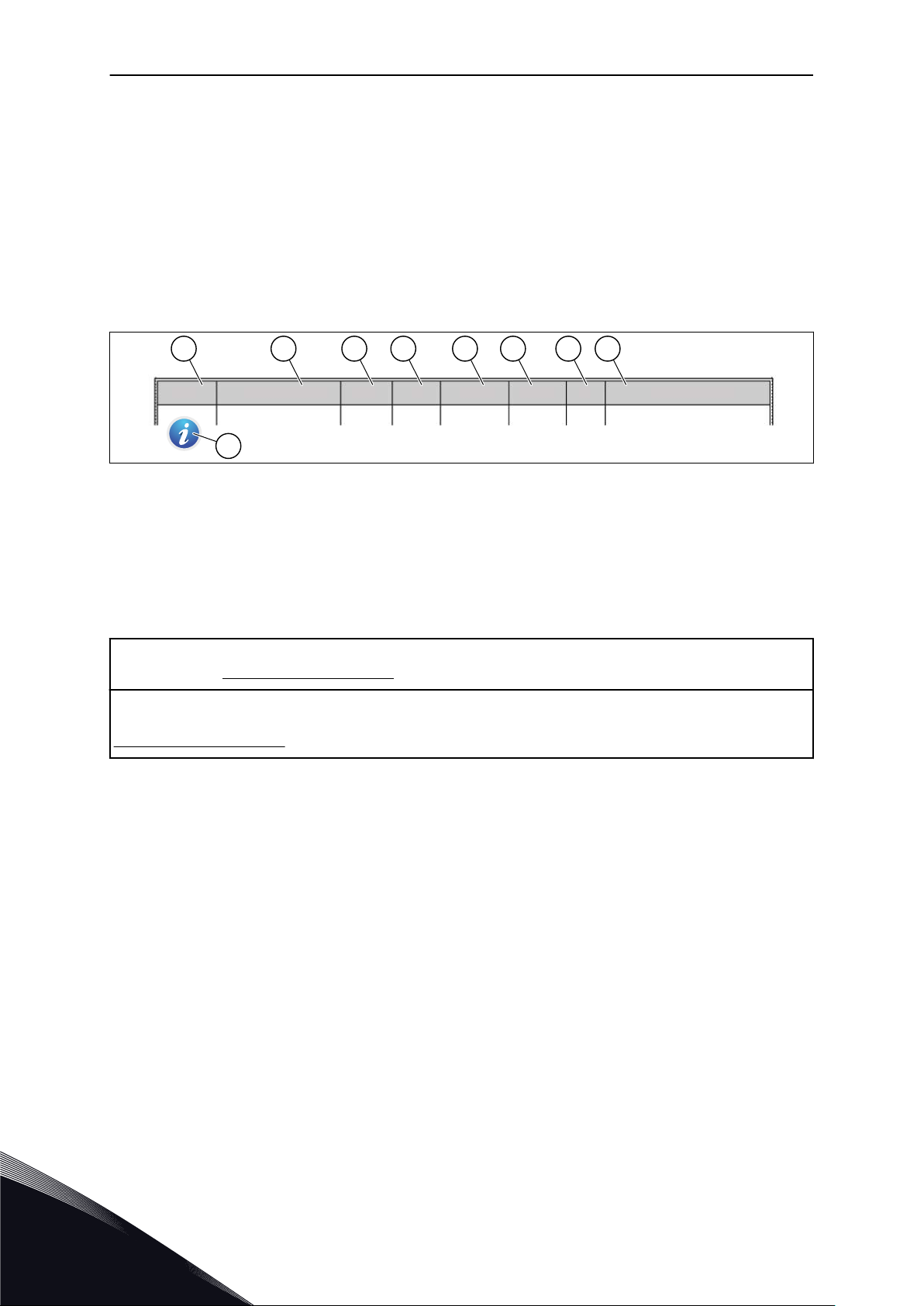
Index Min Max Unit Default ID DescriptionParameter
A
I
B C D E F G H
VACON · 4 PREFACE
Chapter 10, Fault tracing
The faults and their causes.
•
Resetting the faults.
•
Chapter 11, Appendix
Data on the different default values of the applications.
•
This manual includes a large quantity of parameter tables. These instructions tell you how to
read the tables.
A. The location of the parameter in the
menu, that is, the parameter number.
B. The name of the parameter.
C. The minimum value of the parameter.
D. The maximum value of the parameter.
E. The unit of the value of the parameter.
The unit shows if it is available.
NOTE! You can download the English and French product manuals with applicable safety, warning and caution
information from www.vacon.com/downloads.
REMARQUE Vous pouvez télécharger les versions anglaise et française des manuels produit contenant
l'ensemble des informations de sécurité, avertissements et mises en garde applicables sur le site
www.vacon.com/downloads.
F. The value that was set in the factory.
G. The ID number of the parameter.
H. A short description of the values of the
parameter and/or its function.
I. When the symbol shows, you can find
more data about the parameter in
Chapter Parameter descriptions.
TEL. +358 (0)201 2121 · FAX +358 (0)201 212 205
Page 5

PREFACE VACON · 5
FUNCTIONS OF THE VACON® AC DRIVE
Wizards for startup, PID control, multipump and fire mode to make the commissioning
•
easy.
The FUNCT button for an easy change between the local and the remote control place.
•
The remote control place can be I/O or fieldbus. You can make a selection of the remote
control place with a parameter.
8 preset frequencies.
•
Motor pontentiometer functions.
•
A joystick control.
•
A jogging function.
•
2 programmable ramp times, 2 supervisions and 3 ranges of prohibited frequencies.
•
A forced stop.
•
A control page to operate and monitor of the most important values quickly.
•
A fieldbus data mapping.
•
An automatic reset.
•
Different pre-heat modes to prevent condensation problems.
•
A maximum output frequency of 320 Hz.
•
A Real time clock and timer functions (an optional battery is necessary). It is possible to
•
program 3 time channels to get different functions on the drive.
An external PID controller is available. You can use it, for example, to control a valve with
•
the I/O of the AC drive.
A sleep mode function that automatically enables and disables the operation of the drive
•
to save energy.
A 2-zone PID controller with 2 different feedback signals: minimum and maximum
•
control.
2 setpoint sources for the PID control. You can make the selection with a digital input.
•
A function for PID setpoint boost.
•
A feedforward function to make the response to the process changes better.
•
A process value supervision.
•
A multipump control.
•
A maintenance counter.
•
Pump control functions: priming pump control, jockey pump control, pump impeller
•
auto-cleaning, pump input pressure supervision and frost protection function.
24-HOUR SUPPORT +358 (0)201 212 575 · EMAIL: VACON@VACON.COM
Page 6

VACON · 6
TEL. +358 (0)201 2121 · FAX +358 (0)201 212 205
Page 7

TABLE OF CONTENTS VACON · 7
TABLE OF CONTENTS
Preface
About this manual 3
Functions of the Vacon® AC drive 5
1 Quick Startup Guide 11
1.1 Control panel and keypad 11
1.2 The displays 11
1.3 First start-up 12
1.4 Description of the applications 14
1.4.1 Standard application 14
1.4.2 Local/Remote application 21
1.4.3 Multi-step speed application 28
1.4.4 PID control application 35
1.4.5 Multi-purpose application 45
1.4.6 Motor potentiometer application 55
2 Wizards 63
2.1 Standard application wizard 63
2.2 Local/Remote application wizard 64
2.3 Multi-step speed application wizard 65
2.4 PID control application wizard 66
2.5 Multi-purpose application wizard 68
2.6 Motor potentiometer application wizard 69
2.7 Multipump wizard 70
2.8 Fire mode wizard 72
3 User interfaces 74
3.1 Navigation on the keypad 74
3.2 Using the graphical display 76
3.2.1 Editing the values 76
3.2.2 Resetting a fault 79
3.2.3 The FUNCT button 79
3.2.4 Copying the parameters 83
3.2.5 Comparing the parameters 85
3.2.6 Help texts 86
3.2.7 Using the Favourites menu 87
3.3 Using the text display 87
3.3.1 Editing the values 88
3.3.2 Resetting a fault 89
3.3.3 The FUNCT button 89
3.4 Menu structure 93
3.4.1 Quick setup 94
3.4.2 Monitor 94
3.5 Vacon Live 96
24-HOUR SUPPORT +358 (0)201 212 575 · EMAIL: VACON@VACON.COM
Page 8

VACON · 8 TABLE OF CONTENTS
4 Monitoring menu 97
4.1 Monitor group 97
4.1.1 Multimonitor 97
4.1.2 Trend curve 98
4.1.3 Basic 101
4.1.4 I/O 103
4.1.5 Temperature inputs 103
4.1.6 Extras and advanced 105
4.1.7 Timer functions monitoring 107
4.1.8 PID controller monitoring 108
4.1.9 External PID controller monitoring 109
4.1.10 Multipump monitoring 109
4.1.11 Maintenance counters 110
4.1.12 Fieldbus data monitoring 111
5 Parameters menu 113
5.1 Group 3.1: Motor settings 113
5.2 Group 3.2: Start/stop setup 121
5.3 Group 3.3: References 124
5.4 Group 3.4: Ramps and brakes setup 134
5.5 Group 3.5: I/O configuration 137
5.6 Group 3.6: Fieldbus data mapping 151
5.7 Group 3.7: Prohibit frequencies 153
5.8 Group 3.8: Supervisions 154
5.9 Group 3.9: Protections 155
5.10 Group 3.10: Automatic reset 166
5.11 Group 3.11: Application settings 168
5.12 Group 3.12: Timer functions 169
5.13 Group 3.13: PID controller 172
5.14 Group 3.14: External PID controller 188
5.15 Group 3.15: Multipump 193
5.16 Group 3.16: Maintenance counters 195
5.17 Group 3.17: Fire mode 196
5.18 Group 3.18: Motor preheat parameters 198
5.19 Group 3.20: Mechanical brake 200
5.20 Group 3.21: Pump control 201
6 Diagnostics menu 204
6.1 Active faults 204
6.2 Reset faults 204
6.3 Fault history 204
6.4 Total counters 204
6.5 Trip counters 206
6.6 Software info 207
7 I/O and hardware menu 208
7.1 Basic I/O 208
7.2 Option board slots 210
7.3 Real time clock 211
TEL. +358 (0)201 2121 · FAX +358 (0)201 212 205
Page 9

TABLE OF CONTENTS VACON · 9
7.4 Power unit settings 211
7.5 Keypad 213
7.6 Fieldbus 213
8 User settings, favourites and user level menus 218
8.1 User settings 218
8.1.1 Parameter backup 219
8.2 Favourites 219
8.2.1 Adding an item to the Favourites 220
8.2.2 Removing an item from the Favourites 220
8.3 User levels 221
8.3.1 Changing the access code of the user levels 222
9 Parameter descriptions 224
9.1 Motor settings 224
9.1.1 I/f start function 232
9.1.2 Torque stabilator function 233
9.2 Start/Stop setup 234
9.3 References 241
9.3.1 Frequency reference 241
9.3.2 Torque reference 241
9.3.3 Preset frequencies 243
9.3.4 Motor potentiometer parameters 246
9.4 Joystick parameters 248
9.5 Jogging parameters 249
9.6 Ramps and brakes setup 251
9.7 I/O configuration 252
9.7.1 Programming of digital and analogue inputs 252
9.7.2 Default functions of programmable inputs 263
9.7.3 Digital inputs 263
9.7.4 Analogue inputs 264
9.7.5 Digital outputs 269
9.7.6 Analogue outputs 271
9.8 Prohibit frequencies 274
9.9 Supervisions 275
9.9.1 Motor thermal protections 276
9.9.2 Motor stall protection 279
9.9.3 Underload protection 280
9.10 Automatic reset 285
9.11 Timer functions 286
9.12 PID controller 290
9.12.1 Feedforward 291
9.12.2 Sleep function 291
9.12.3 Feedback supervision 293
9.12.4 Pressure loss compensation 294
9.12.5 Soft fill 296
9.12.6 Input pressure supervision 297
9.12.7 Frost protection 298
24-HOUR SUPPORT +358 (0)201 212 575 · EMAIL: VACON@VACON.COM
Page 10

VACON · 10 TABLE OF CONTENTS
9.13 Multipump function 299
9.14 Maintenance counters 305
9.15 Fire mode 305
9.16 Motor preheat function 307
9.17 Mechanical brake 308
9.18 Pump control 311
9.18.1 Auto-cleaning 311
9.18.2 Jockey pump 312
9.18.3 Priming pump 313
9.19 Total and trip counters 314
9.19.1 Operating time counter 314
9.19.2 Operating time trip counter 315
9.19.3 Run time counter 315
9.19.4 Power on time counter 316
9.19.5 Energy counter 316
9.19.6 Energy trip counter 317
10 Fault tracing 319
10.1 A fault comes into view 319
10.1.1 Resetting with the Reset button 319
10.1.2 Resetting with a parameter in the graphical display 319
10.1.3 Resetting with a parameter in the text display 320
10.2 Fault history 321
10.2.1 Examining the Fault history in the graphical display 321
10.2.2 Examining the Fault history in the text display 322
10.3 Fault codes 324
11 Appendix 1 337
11.1 The default values of parameters in the different applications 337
TEL. +358 (0)201 2121 · FAX +358 (0)201 212 205
Page 11
A B C
I
H D
G F E
QUICK STARTUP GUIDE VACON · 11
1 QUICK STARTUP GUIDE
1.1 CONTROL PANEL AND KEYPAD
The control panel is the interface between the AC drive and the user. With the control panel,
you can control the speed of a motor and monitor the status of the AC drive. You can also set
the parameters of the AC drive.
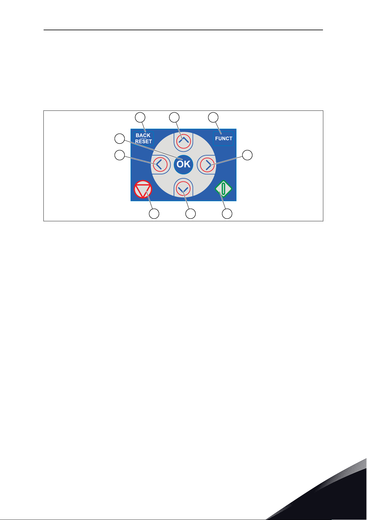
Fig. 1: The buttons of the keypad
A. The BACK/RESET button. Use it to move
back in the menu, exit the Edit mode,
reset a fault.
B. The arrow button UP. Use it to scroll the
menu up and to increase a value.
C. The FUNCT button. Use it to change the
rotation direction of the motor, access
the control page, and change the control
place. See more in Table 38 Frequency
reference parameters.
D. The arrow button RIGHT.
E. The START button.
F. The arrow button DOWN. Use it to scroll
the menu down and to decrease a value.
G. The STOP button.
H. The arrow button LEFT. Use it to move
the cursor left.
I. The OK button. Go into an active level or
item, accept a selection.
1.2 THE DISPLAYS
There are 2 display types: the graphical display and the text display. The control panel always
has the same keypad and buttons.
The display shows this data.
The status of the motor and the drive.
•
Faults in the motor and in the drive.
•
Your location in the menu structure.
•
24-HOUR SUPPORT +358 (0)201 212 575 · EMAIL: VACON@VACON.COM
1
Page 12
STOP
READY I/O
Main Menu
A B C D E
F
H
G
Quick Setup
( 17 )
Monitor
( 5 )
Parameters
( 12 )
M1ID:
A B
F
C
D
E
VACON · 12 QUICK STARTUP GUIDE
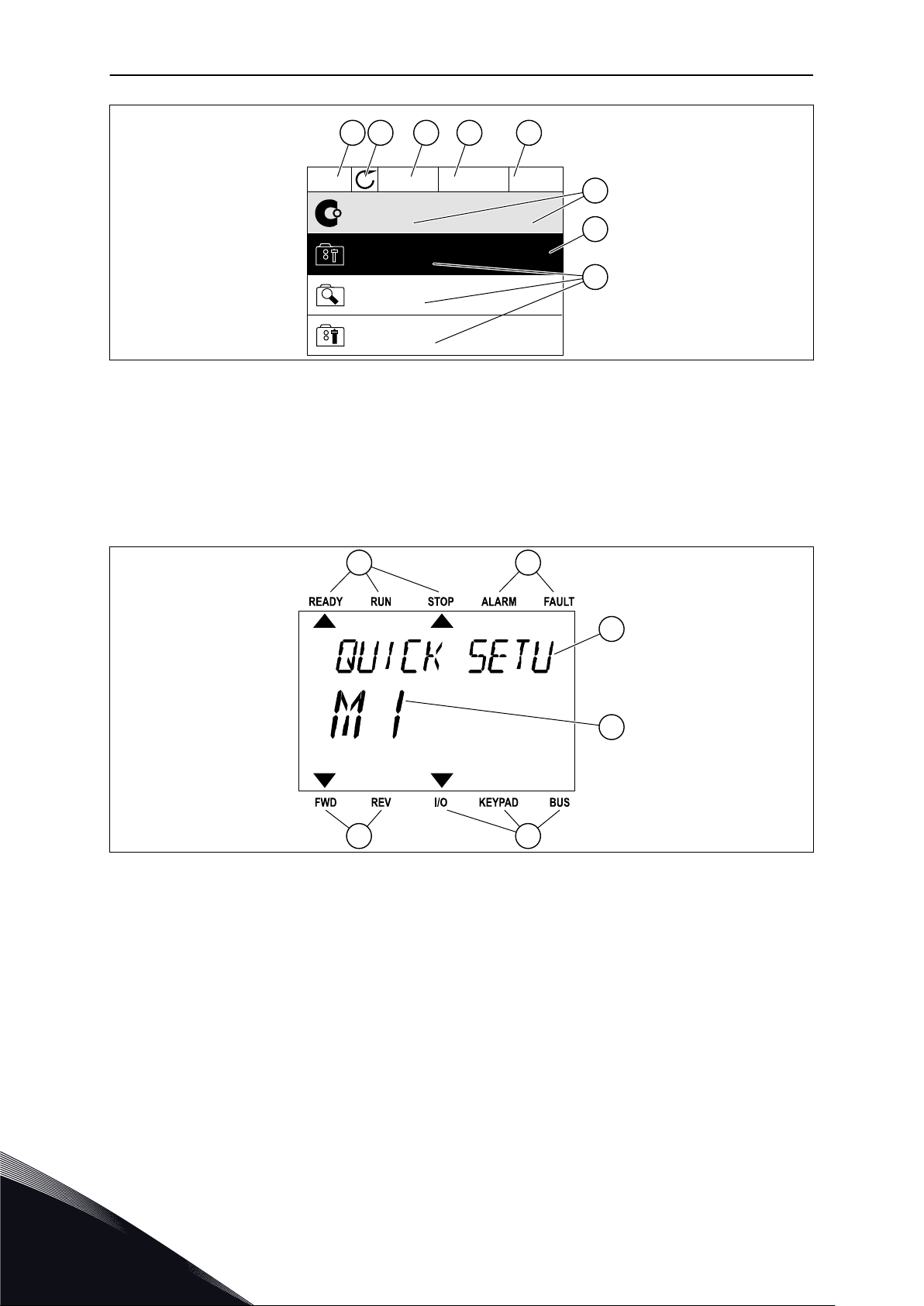
Fig. 2: The graphical display
A. The first status field: STOP/RUN
B. The rotation direction of the motor
C. The second status field: READY/NOT
READY/FAULT
D. The alarm field: ALARM/E. The control place field: PC/IO/KEYPAD/
F. The location field: the ID number of the
parameter and the current location in
the menu
G. An activated group or item
H. The number of items in the group in
question
FIELDBUS
Fig. 3: The text display. If the text is too long to show, the text scrolls automatically on the display.
A. The indicators of status
B. The indicators of alarm and fault
C. The name of the group or item of the
current location
1.3 FIRST START-UP
1
The Start-up wizard tells you to give necessary data for the drive to control your procedure.
D. The current location in the menu
E. The indicators of the control place
F. The indicators of the rotation direction
TEL. +358 (0)201 2121 · FAX +358 (0)201 212 205
Page 13

QUICK STARTUP GUIDE VACON · 13
1
2
3 Time* (P5.5.2) hh:mm:ss
4 Year* (P5.5.4) yyyy
5 Date* (P5.5.3) dd.mm.
Language selection (P6.1) The selection is different in all the language
packages
Daylight saving* (P5.5.5)
Russia
US
EU
OFF
* If a battery is installed, you see these questions.
Run Startup wizard?
6
Yes
No
To set the parameter values manually, make the selection No and push the OK button.
Make a selection of an application (P1.2 Application,
ID212)
7
Set a value for P3.1.2.2 Motor Type (so that it agrees
8
9
10
11
12 Set a value for P3.1.1.4 Motor Nominal Current Range: Varies
13 Set a value for P3.1.1.5 Motor Cos Phi Range: 0.30-1.00
with the nameplate)
Set a value for P3.1.1.1 Motor Nominal Voltage (so
that it agrees with the nameplate)
Set a value for P3.1.1.2 Motor Nominal Frequency
(so that it agrees with the nameplate)
Set a value for P3.1.1.3 Motor Nominal Speed (so
that it agrees with the nameplate)
Standard
Local/Remote
Multi-step speed
PID control
Multi-purpose
Motor potentiometer
PM motor
Induction motor
Range: Varies
Range: 8.00...320.00 Hz
Range: 24...19200
If you set Motor Type to Induction Motor, you see the next question. If your selection is PM
Motor, the value of parameter P3.1.1.5 Motor Cos Phi is set to 1.00 and the wizard goes
directly to question 14.
24-HOUR SUPPORT +358 (0)201 212 575 · EMAIL: VACON@VACON.COM
1
Page 14

VACON · 14 QUICK STARTUP GUIDE
14
15
16 Set a value for P3.4.1.2 Acceleration Time 1 Range: 0.1...300.0 s
17 Set a value for P3.4.1.3 Deceleration Time 1 Range: 0.1...300.0 s
18
Set a value for P3.3.1.1 Minimum Frequency
Reference
Set a value for P3.3.1.2 Maximum Frequency
Reference
Run the Application wizard?
Range: 0.00...P3.3.1.2 Hz
Range: P3.3.1.1...320.00 Hz
Yes
No
To continue to the application wizard, set the selection to Yes and push the OK button. See
the description of the different application wizards in Chapter 2 Wizards.
After these selections, the Start-up wizard is completed. To start the Start-up wizard again,
you have 2 alternatives. Go to the parameter P6.5.1 Restore Factory Defaults or to the
parameter B1.1.2 Start-up Wizard. Then set the value to Activate.
1.4 DESCRIPTION OF THE APPLICATIONS
Use the parameter P1.2 (Application) to make a selection of an application for the drive.
Immediately when the parameter P1.2 changes, a group of parameters get their preset
values.
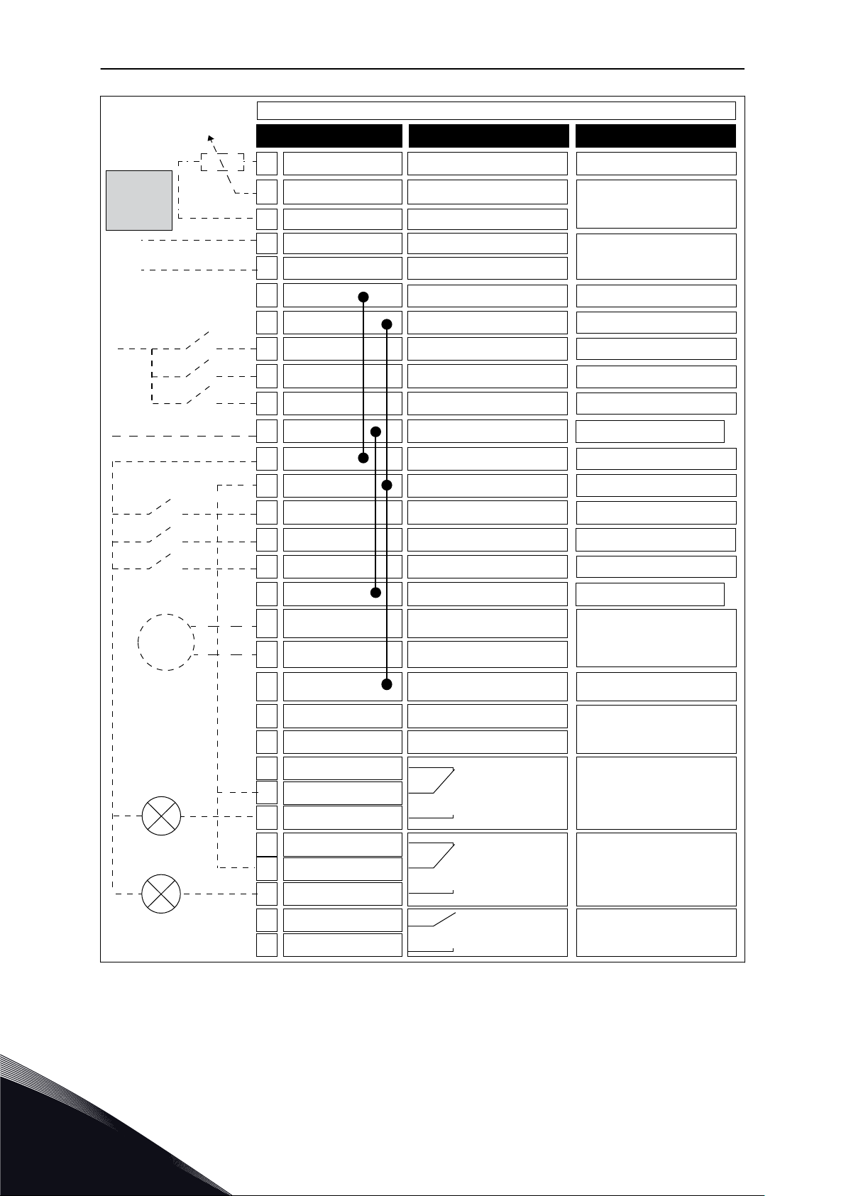
1.4.1 STANDARD APPLICATION
You can use the Standard application in speed-controlled processes where no special
functions are necessary, for example pumps, fans, or conveyors.
It is possible to control the drive from the keypad, Fieldbus or I/O terminal.
When you control the drive with the I/O terminal, the frequency reference signal is connected
to AI1 (0…10V) or AI2 (4…20mA). The connection depends the type of the signal. There are
also 3 preset frequency references available. You can activate the preset frequency
references with DI4 and DI5. The start/stop signals of the drive are connected to DI1 (start
forward) and DI2 (start reverse).
It is possible to configure all the drive outputs freely in all the applications. There are 1
analogue output (Output Frequency) and 3 relay outputs (Run, Fault, Ready) available on the
basic I/O board.
1
TEL. +358 (0)201 2121 · FAX +358 (0)201 212 205
Page 15
RUN
FAULT
READY
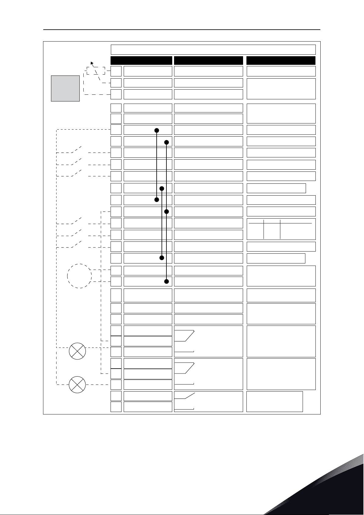
Reference output+10 Vref
Terminal
Standard I/O board
Signal
1
24V auxiliary voltage24Vout6
Analogue input 1 +AI1+2
AI1-3
Analogue input 2 +
AI2+4
AI2-5
Analogue output 1 +
AO1+
RUN
18
Analogue output 1 -
AO1-19
+24Vin
30
24V auxiliary voltage24Vout
12
I/O groundGND7
I/O groundGND13
Digital input 1DI18
Digital input 2DI29
Digital input 3DI310
Digital input 4DI414
Digital input 5DI515
Digital input 6DI616
Relay output 1
RO1/1 NC21
22
RO1/2 CM
RO1/3 NO23
Common for DI1-DI6CM11
Common for DI1-DI6CM
17
Serial bus, negativeRS485A
Serial bus, positiveRS485
B
Relay output 2
Relay output 3
RO2/1 NC24
25
RO2/2 CM
RO2/3 NO26
32
RO3/2 CM
RO3/3 NO33
Description
Frequency reference
(default 0...10V)
Frequency reference
(Default 4...20mA)
Start forward
Start reverse
External fault
DI4
DI5
Freq. ref.
Open
Closed
Open
Closed
Open
Open
Closed
Closed
Analog input 1
Preset Freq. 1
Preset Freq. 2
Preset Freq. 3
Fault reset
Output frequency
(default: 0...20mA)
Modbus RTU
N2, BACnet
Analogue input 1 -
FAULT
Analogue input 2 -
Reference
potentiom-
eter
1...10kΩ
mA
*)
*)
**)
24V auxiliary
input voltage
QUICK STARTUP GUIDE VACON · 15
Fig. 4: The default control connections of the Standard application
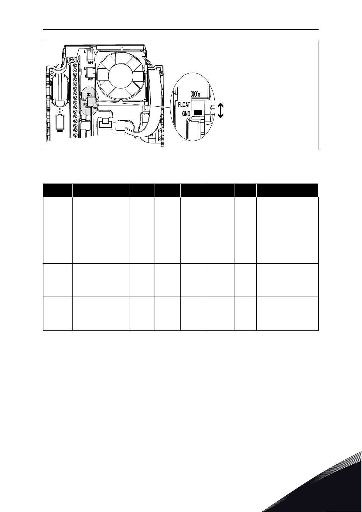
* = You can isolate the digital inputs from the ground with a DIP switch.
24-HOUR SUPPORT +358 (0)201 212 575 · EMAIL: VACON@VACON.COM
1
Page 16

Digital inputs
Floating
Connected to GND
(Default!)
VACON · 16 QUICK STARTUP GUIDE
Fig. 5: The DIP switch
Table 2: M1.1 Wizards
Index Parameter Min Max Unit Default ID Description
1.1.1 Startup wizard 0 1 0 1170
1.1.3 Multi-pump Wizard 0 1 0 1671
1.1.4 Fire mode Wizard 0 1 0 1672
0 = Do not activate
1 = Activate
The selection Activate
starts the Start-up
wizard (see Chapter
Table 1 The Start-up
wizard.
The selection Activate
starts the Multipump
wizard (see Chapter
2.7 Multipump wizard).
The selection Activate
starts the Fire mode
wizard (see Chapter
2.8 Fire mode wizard).
1
TEL. +358 (0)201 2121 · FAX +358 (0)201 212 205
Page 17

QUICK STARTUP GUIDE VACON · 17
Table 3: M1 Quick Setup
Index Parameter Min Max Unit Default ID Description
0 = Standard
1.2
Application 0 5 0 212
1 = Local/Remote
2 = Multi-Step Speed
3 = PID Control
4 = Multi-Purpose
5 = Motor
Potentiometer
1.3
1.4
1.5 Acceleration Time 1 0.1 300.0 s 5.0 103
1.6 Deceleration Time 1 0.1 300.0 s 5.0 104
1.7 Motor Current Limit IH*0.1 I
Minimum Frequency
Reference
Maximum Frequency
Reference
0.00 P1.4 Hz 0.0 101
P1.3 320.0 Hz
S
A Varies 107
50.0 /
60.0
102
The minimum
frequency reference
that is acceptable.
The maximum
frequency reference
that is acceptable.
Gives the quantity of
time that is necessary
for the output
frequency to increase
from zero frequency to
the maximum
frequency.
Gives the quantity of
time that is necessary
for the output
frequency to decrease
from the maximum
frequency to zero
frequency.
The maximum motor
current from the AC
drive.
1.8 Motor Type 0 1 0 650
1.9
24-HOUR SUPPORT +358 (0)201 212 575 · EMAIL: VACON@VACON.COM
Motor Nominal
Voltage
Varies Varies V Varies 110
0 = Induction Motor
1 = Permanent Magnet
Motor
Find this value Un on
the rating plate of the
motor.
NOTE!
Find out if the motor
connection is Delta or
Star.
1
Page 18

VACON · 18 QUICK STARTUP GUIDE
Table 3: M1 Quick Setup
Index Parameter Min Max Unit Default ID Description
1.10
1.11
1.12
1.13
1.14 Energy Optimization 0 1 0 666
Motor Nominal
Frequency
Motor Nominal
Speed
Motor Nominal
Current
Motor Cos Phi
(Power Factor)
8.0 320.0 Hz 50 / 60 111
24 19200 Rpm Varies 112
IH * 0.1 IH * 2 A Varies 113
0.30 1.00 Varies 120
Find this value fn on
the rating plate of the
motor.
Find this value nn on
the rating plate of the
motor.
Find this value In on
the rating plate of the
motor.
Find this value on the
rating plate of the
motor.
The drive searches for
the minimum motor
current to save energy
and to lower the motor
noise. Use this function
with, for example, fan
and pump processes.
0 = Disabled
1 = Enabled
1.15 Identification 0 2 0 631
1.16
1.17 Stop Function 0 1 0 506
Start Function 0 1 0 505
The identification run
calculates or measures
the motor parameters
that are necessary for
a good control of the
motor and speed.
0 = No action
1 = At standstill
2 = With rotation
Before you do the
identification run, you
must set the motor
nameplate parameters.
0 = Ramping
1 = Flying Start
0 = Coasting
1 = Ramping
1
TEL. +358 (0)201 2121 · FAX +358 (0)201 212 205
Page 19

QUICK STARTUP GUIDE VACON · 19
Table 3: M1 Quick Setup
Index Parameter Min Max Unit Default ID Description
1.18 Automatic Reset 0 1 0 731
1.19
1.20
1.21
Response to External
Fault
Response to AI Low
Fault
Remote Control
Place
0 3 2 701
0 5 0 700
0 1 0 172
0 = Disabled
1 = Enabled
0 = No action
1 = Alarm
2 = Fault (Stop
according to stop
mode)
3 = Fault (Stop by
coasting)
0 = No action
1 = Alarm
2 = Alarm+preset fault
frequency (P3.9.1.13)
3 = Alarm + previous
frequency
4 = Fault (Stop
according to stop
mode)
5 = Fault (Stop by
coasting)
The selection of the
remote control place
(start/stop).
0 = I/O control
1 = Fieldbus control
24-HOUR SUPPORT +358 (0)201 212 575 · EMAIL: VACON@VACON.COM
1
Page 20

VACON · 20 QUICK STARTUP GUIDE
Table 3: M1 Quick Setup
Index Parameter Min Max Unit Default ID Description
The selection of the
frequency reference
source when the
control place is I/O A.
0 = Preset Frequency 0
1 = Keypad Reference
2 = Fieldbus
3 = AI1
4 = AI2
5 = AI1+AI2
6 = PID Reference
7 = Motor
Potentiometer
8 = Joystick Reference
9 = Jogging Reference
10 = Block Out.1
11 = Block Out.2
12 = Block Out.3
13 = Block Out.4
14 = Block Out.5
15 = Block Out.6
16 = Block Out.7
17 = Block Out.8
18 = Block Out.9
19 = Block Out.10
1.22
I/O Control
Reference A
Selection
0 9 5 117
The application that
you set with parameter
1.2 gives the default
value.
The selection of the
1.23
1.24
1.25 AI1 Signal Range 0 1 0 379
1.26 AI2 Signal Range 0 1 1 390
1.27 RO1 Function 0 51 2 1101 See P3.5.3.2.1
Keypad Control
Reference Selection
Fieldbus Control
Reference Selection
0 9 1 121
0 9 2 122
frequency reference
source when the
control place is keypad.
See P1.22.
The selection of the
frequency reference
source when the
control place is
fieldbus. See P1.22.
0= 0..10V / 0..20mA
1= 2..10V / 4..20mA
0= 0..10V / 0..20mA
1= 2..10V / 4..20mA
1
TEL. +358 (0)201 2121 · FAX +358 (0)201 212 205
Page 21

QUICK STARTUP GUIDE VACON · 21
Table 3: M1 Quick Setup
Index Parameter Min Max Unit Default ID Description
1.28 RO2 Function 0 51 3 1104 See P3.5.3.2.1
1.29 RO3 Function 0 51 1 1107 See P3.5.3.2.1
1.30 AO1 Function 0 31 2 10050 See P3.5.4.1.1
Table 4: M1.31 Standard
Index Parameter Min Max Unit Default ID Description
Make the selection of a
1.31.1 Preset Frequency 1 P1.3 P1.4 Hz 10.0 105
1.31.2 Preset Frequency 2 P1.3 P1.4 Hz 15.0 106
preset frequency with
the digital input DI4.
Make the selection of a
preset frequency with
the digital input DI5.
Make the selection of a
1.31.3 Preset Frequency 3 P1.3 P1.4 Hz 20.0 126
preset frequency with
the digital input DI4
and DI5.
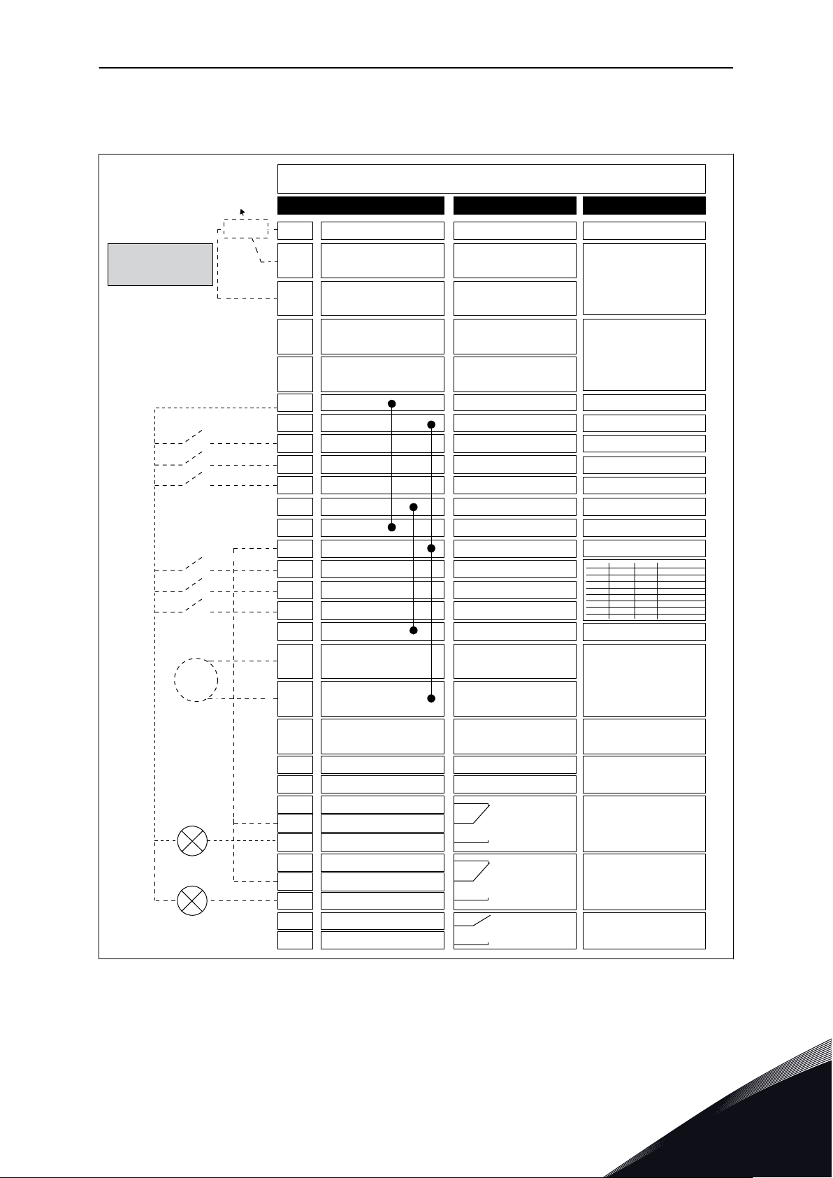
1.4.2 LOCAL/REMOTE APPLICATION
Use the Local/Remote application when, for example, it is necessary to switch between 2
different control places.
To change between the Local and the Remote control place, use DI6. When Remote control is
active, you can give the start/stop commands from Fieldbus or from I/O terminal (DI1 and
DI2). When Local control is active, you can give the start/stop commands from the keypad,
Fieldbus or I/O terminal (DI4 and DI5).
For each control place, you can make a selection of the frequency reference from the
keypad, Fieldbus or I/O terminal (AI1 or AI2).
It is possible to configure all the drive outputs freely in all the applications. There are 1
analogue output (Output Frequency) and 3 relay outputs (Run, Fault, Ready) available on the
basic I/O board.
24-HOUR SUPPORT +358 (0)201 212 575 · EMAIL: VACON@VACON.COM
1
Page 22
REMOTE:
Frequency reference
(default: 4...20mA)
RUN
FAULT
READY
Analogue input 1 +
Analogue input 1 -
Analogue input 2 +
Analogue input 2 -
Reference output+10 Vref
Terminal Signal
1
24V auxiliary voltage24Vout6
Remote reference
(4...20mA)
AI1+2
AI1-
3
AI2+4
AI2-5
AO1+
RUN
18
AO1-/GND19
+24Vin
30
24V auxiliary voltage24Vout
12
I/O groundGND7
I/O groundGND13
Digital input 1DI18
Digital input 2DI29
Digital input 3DI310
Digital input 4DI414
Digital input 5DI515
Digital input 6DI616
Relay output 1RO1/1 NC21
22
RO1/2 CM
RO1/3 NO23
Common for DI1-DI6CM11
Common for DI1-DI6CM
17
Serial bus, negativeRS485A
Serial bus, positiveRS485
B
Relay output 2
Relay output 3
RO2/1 NC24
25
RO2/2 CM
RO2/3 NO26
32
RO3/2 CM
RO3/3 NO33
Description
REMOTE: Start forward
REMOTE: Start reverse
External fault
Output frequency
(default: 0...20mA)
Modbus RTU
BACnet, N2
LOCAL: Start forward
LOCAL: Start reverse
LOCAL/REMOTE
selection
Remote
control ground
Analogue output 1 +
Analogue output 1 -
FAULT
Reference
potentiom-
eter
1...10kΩ
Remote
control
(+24V)
mA
*)
*)
24V auxiliary
input voltage
LOCAL:
Frequency reference
(default: 0...10V)
Standard I/O board
VACON · 22 QUICK STARTUP GUIDE
1
Fig. 6: The default control connections of the Local/Remote application
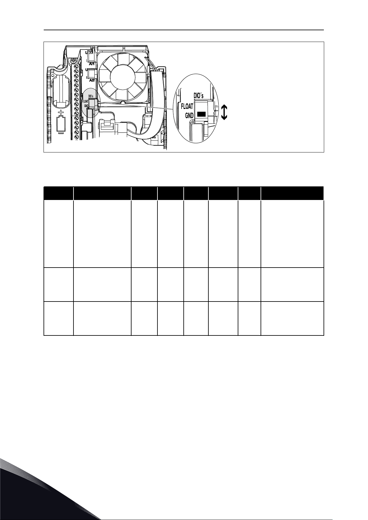
* = You can isolate the digital inputs from the ground with a DIP switch.
TEL. +358 (0)201 2121 · FAX +358 (0)201 212 205
Page 23
Digital inputs
Floating
Connected to GND
(Default!)
QUICK STARTUP GUIDE VACON · 23
Fig. 7: The DIP switch
Table 5: M1.1 Wizards
Index Parameter Min Max Unit Default ID Description
1.1.1 Startup wizard 0 1 0 1170
1.1.3 Multi-pump Wizard 0 1 0 1671
1.1.4 Fire mode Wizard 0 1 0 1672
0 = Do not activate
1 = Activate
The selection Activate
starts the Start-up
wizard (see Chapter
Table 1 The Start-up
wizard.
The selection Activate
starts the Multipump
wizard (see Chapter
2.7 Multipump wizard).
The selection Activate
starts the Fire mode
wizard (see Chapter
2.8 Fire mode wizard).
24-HOUR SUPPORT +358 (0)201 212 575 · EMAIL: VACON@VACON.COM
1
Page 24

VACON · 24 QUICK STARTUP GUIDE
Table 6: M1 Quick Setup
Index Parameter Min Max Unit Default ID Description
0 = Standard
1.2
Application 0 5 1 212
1 = Local/Remote
2 = Multi-Step Speed
3 = PID Control
4 = Multi-Purpose
5 = Motor
Potentiometer
1.3
1.4
1.5 Acceleration Time 1 0.1 300.0 s 5.0 103
1.6 Deceleration Time 1 0.1 300.0 s 5.0 104
1.7 Motor Current Limit IH*0.1 I
Minimum Frequency
Reference
Maximum Frequency
Reference
0.00 P1.4 Hz 0.0 101
P1.3 320.0 Hz
S
A Varies 107
50.0 /
60.0
102
The minimum
frequency reference
that is acceptable.
The maximum
frequency reference
that is acceptable.
Gives the quantity of
time that is necessary
for the output
frequency to increase
from zero frequency to
the maximum
frequency.
Gives the quantity of
time that is necessary
for the output
frequency to decrease
from the maximum
frequency to zero
frequency.
The maximum motor
current from the AC
drive.
1
1.8 Motor Type 0 1 0 650
1.9
Motor Nominal
Voltage
Varies Varies V Varies 110
TEL. +358 (0)201 2121 · FAX +358 (0)201 212 205
0 = Induction Motor
1 = Permanent Magnet
Motor
Find this value Un on
the rating plate of the
motor.
NOTE!
Find out if the motor
connection is Delta or
Star.
Page 25

QUICK STARTUP GUIDE VACON · 25
Table 6: M1 Quick Setup
Index Parameter Min Max Unit Default ID Description
1.10
1.11
1.12
1.13
1.14 Energy Optimization 0 1 0 666
Motor Nominal
Frequency
Motor Nominal
Speed
Motor Nominal
Current
Motor Cos Phi
(Power Factor)
8.0 320.0 Hz 50 / 60 111
24 19200 Rpm Varies 112
IH * 0.1 IH * 2 A Varies 113
0.30 1.00 Varies 120
Find this value fn on
the rating plate of the
motor.
Find this value nn on
the rating plate of the
motor.
Find this value In on
the rating plate of the
motor.
Find this value on the
rating plate of the
motor.
The drive searches for
the minimum motor
current to save energy
and to lower the motor
noise. Use this function
with, for example, fan
and pump processes.
0 = Disabled
1 = Enabled
1.15 Identification 0 2 0 631
1.16
1.17 Stop Function 0 1 0 506
Start Function 0 1 0 505
The identification run
calculates or measures
the motor parameters
that are necessary for
a good control of the
motor and speed.
0 = No action
1 = At standstill
2 = With rotation
Before you do the
identification run, you
must set the motor
nameplate parameters.
0 = Ramping
1 = Flying Start
0 = Coasting
1 = Ramping
24-HOUR SUPPORT +358 (0)201 212 575 · EMAIL: VACON@VACON.COM
1
Page 26

VACON · 26 QUICK STARTUP GUIDE
Table 6: M1 Quick Setup
Index Parameter Min Max Unit Default ID Description
1.18 Automatic Reset 0 1 0 731
1.19
1.20
1.21
Response to External
Fault
Response to AI Low
Fault
Remote Control
Place
0 3 2 701
0 5 0 700
0 1 0 172
0 = Disabled
1 = Enabled
0 = No action
1 = Alarm
2 = Fault (Stop
according to stop
mode)
3 = Fault (Stop by
coasting)
0 = No action
1 = Alarm
2 = Alarm+preset fault
frequency (P3.9.1.13)
3 = Alarm + previous
frequency
4 = Fault (Stop
according to stop
mode)
5 = Fault (Stop by
coasting)
The selection of the
remote control place
(start/stop).
0 = I/O control
1 = Fieldbus control
1
TEL. +358 (0)201 2121 · FAX +358 (0)201 212 205
Page 27

QUICK STARTUP GUIDE VACON · 27
Table 6: M1 Quick Setup
Index Parameter Min Max Unit Default ID Description
The selection of the
frequency reference
source when the
control place is I/O A.
0 = Preset Frequency 0
1 = Keypad Reference
2 = Fieldbus
3 = AI1
4 = AI2
5 = AI1+AI2
6 = PID Reference
7 = Motor
Potentiometer
8 = Joystick Reference
9 = Jogging Reference
10 = Block Out.1
11 = Block Out.2
12 = Block Out.3
13 = Block Out.4
14 = Block Out.5
15 = Block Out.6
16 = Block Out.7
17 = Block Out.8
18 = Block Out.9
19 = Block Out.10
1.22
I/O Control
Reference A
Selection
0 9 3 117
The application that
you set with parameter
1.2 gives the default
value.
The selection of the
1.23
1.24
1.25 AI1 Signal Range 0 1 0 379
1.26 AI2 Signal Range 0 1 1 390
1.27 RO1 Function 0 51 2 1101 See P3.5.3.2.1
Keypad Control
Reference Selection
Fieldbus Control
Reference Selection
0 9 1 121
0 9 2 122
frequency reference
source when the
control place is keypad.
See P1.22.
The selection of the
frequency reference
source when the
control place is
fieldbus. See P1.22.
0= 0..10V / 0..20mA
1= 2..10V / 4..20mA
0= 0..10V / 0..20mA
1= 2..10V / 4..20mA
24-HOUR SUPPORT +358 (0)201 212 575 · EMAIL: VACON@VACON.COM
1
Page 28

VACON · 28 QUICK STARTUP GUIDE
Table 6: M1 Quick Setup
Index Parameter Min Max Unit Default ID Description
1.28 RO2 Function 0 51 3 1104 See P3.5.3.2.1
1.29 RO3 Function 0 51 1 1107 See P3.5.3.2.1
1.30 AO1 Function 0 31 2 10050 See P3.5.4.1.1
Table 7: M1.32 Local/Remote
Index Parameter Min Max Unit Default ID Description
I/O Control
1.32.1
1.32.2 I/O B Control Force
1.32.3
1.32.4 Control Signal 1 B
1.32.5 Control Signal 2 B
1.32.6
1.32.7
1.32.8
Reference B
Selection
I/O B Reference
Force
Keypad Control
Force
Fieldbus Control
Force
External Fault
(Close)
1 20 4 131
DigIN
SlotA.6
DigIN
SlotA.6
DigIN
SlotA.4
DigIN
SlotA.5
DigIN
SlotA.1
DigIN
Slot0.1
DigIN
SlotA.3
425
343
423
424
410
411
405
See P1.22
TRUE = Force control
place to I/O B
TRUE = Used frequency
reference is specified
by I/O Reference B
parameter (P1.32.1)
Start signal 1 when
control place is I/O B
Start signal 1 when
control place is I/O B
Force Control to
Keypad
Force Control to
Fieldbus
FALSE = OK
TRUE = External fault
1
1.32.9 Fault Reset (Close)
DigIN
Slot0.1
Resets all active faults
414
when TRUE
1.4.3 MULTI-STEP SPEED APPLICATION
You can use the Multi-step speed application with processes where more than 1 fixed
frequency reference is necessary (for example test benches).
It is possible to use 1 + 7 frequency references: 1 basic reference (AI1 or AI2) and 7 preset
references.
Make a selection of the preset frequency references with digital signals DI4, DI5 and DI6. If
none of these inputs are active, the frequency reference is removed from the analogue input
(AI1 or AI2). Give the start/stop commands from the I/O terminal (DI1 and DI2).
TEL. +358 (0)201 2121 · FAX +358 (0)201 212 205
Page 29
*)
*)
mA
DI4DI5
1
FAULT
DI6
000
1
0
0
1
00
1
1
1
1
1
0
0
0
RUN
0
1
1
1
10
1
6
2
3
4
5
AO1+
RUN
18
AO1-19
+24Vin30
24Vout
12
GND7
GND13
DI18
DI29
DI310
DI414
DI515
DI616
RO1/1 NC21
22
RO1/2 CM
RO1/3 NO23
CM11
CM
17
RS485A
RS485
B
RO2/1 NC24
25
RO2/2 CM
RO2/3 NO26
32
RO3/2 CM
RO3/3 NO33
Reference
potentiometer
1...10 kΩ
Standard I/O board
Terminal Signal Description
+10Vref
AI1+
AI1-
AI2+
AI2-
24Vout
Reference output
Analogue input 1 +
Analogue input 1 -
Analogue input 2 +
Analogue input 2 -
Frequency
reference
(default 0...10V)
Frequency
reference
(default 4...20mA)
24V auxiliary voltage
I/O ground
Digital input 1
Digital input 2
Digital input 3
Digital input 4
Digital input 5
Digital input 6
Start forward
Start reverse
External fault
Common for DI1-DI6
Common for DI1-DI6
24V auxiliary voltage
I/O ground
Analogue output 1 +
Analogue output 1 -
24V auxiliary
input voltage
Output
frequency
(default:
0...20mA)
Modbus RTU,
BACnet, N2
READY
Serial bus, negative
Serial bus, positive
Relay output 1
Relay output 2
Relay output 3
Analog input
Preset Freq. 1
Preset Freq. 2
Preset Freq. 3
Preset Freq. 4
Preset Freq. 5
Preset Freq. 6
Preset Freq. 7
Freq. ref.
FAULT
QUICK STARTUP GUIDE VACON · 29
It is possible to configure all the drive outputs freely in all the applications. There are 1
analogue output (Output Frequency) and 3 relay outputs (Run, Fault, Ready) available on the
basic I/O board.
Fig. 8: The default control connections of the Multi-step speed application
* = You can isolate the digital inputs from the ground with a DIP switch.
24-HOUR SUPPORT +358 (0)201 212 575 · EMAIL: VACON@VACON.COM
1
Page 30
Digital inputs
Floating
Connected to GND
(Default!)
VACON · 30 QUICK STARTUP GUIDE
Fig. 9: The DIP switch
Table 8: M1.1 Wizards
Index Parameter Min Max Unit Default ID Description
1.1.1 Startup wizard 0 1 0 1170
1.1.3 Multi-pump Wizard 0 1 0 1671
1.1.4 Fire mode Wizard 0 1 0 1672
0 = Do not activate
1 = Activate
The selection Activate
starts the Start-up
wizard (see Chapter
Table 1 The Start-up
wizard.
The selection Activate
starts the Multipump
wizard (see Chapter
2.7 Multipump wizard).
The selection Activate
starts the Fire mode
wizard (see Chapter
2.8 Fire mode wizard).
1
TEL. +358 (0)201 2121 · FAX +358 (0)201 212 205
Page 31

QUICK STARTUP GUIDE VACON · 31
Table 9: M1 Quick Setup
Index Parameter Min Max Unit Default ID Description
0 = Standard
1.2
Application 0 5 2 212
1 = Local/Remote
2 = Multi-Step Speed
3 = PID Control
4 = Multi-Purpose
5 = Motor
Potentiometer
1.3
1.4
1.5 Acceleration Time 1 0.1 300.0 s 5.0 103
1.6 Deceleration Time 1 0.1 300.0 s 5.0 104
1.7 Motor Current Limit IH*0.1 I
Minimum Frequency
Reference
Maximum Frequency
Reference
0.00 P1.4 Hz 0.0 101
P1.3 320.0 Hz
S
A Varies 107
50.0 /
60.0
102
The minimum
frequency reference
that is acceptable.
The maximum
frequency reference
that is acceptable.
Gives the quantity of
time that is necessary
for the output
frequency to increase
from zero frequency to
the maximum
frequency.
Gives the quantity of
time that is necessary
for the output
frequency to decrease
from the maximum
frequency to zero
frequency.
The maximum motor
current from the AC
drive.
1.8 Motor Type 0 1 0 650
1.9
24-HOUR SUPPORT +358 (0)201 212 575 · EMAIL: VACON@VACON.COM
Motor Nominal
Voltage
Varies Varies V Varies 110
0 = Induction Motor
1 = Permanent Magnet
Motor
Find this value Un on
the rating plate of the
motor.
NOTE!
Find out if the motor
connection is Delta or
Star.
1
Page 32

VACON · 32 QUICK STARTUP GUIDE
Table 9: M1 Quick Setup
Index Parameter Min Max Unit Default ID Description
1.10
1.11
1.12
1.13
1.14 Energy Optimization 0 1 0 666
Motor Nominal
Frequency
Motor Nominal
Speed
Motor Nominal
Current
Motor Cos Phi
(Power Factor)
8.0 320.0 Hz 50 / 60 111
24 19200 Rpm Varies 112
IH * 0.1 IH * 2 A Varies 113
0.30 1.00 Varies 120
Find this value fn on
the rating plate of the
motor.
Find this value nn on
the rating plate of the
motor.
Find this value In on
the rating plate of the
motor.
Find this value on the
rating plate of the
motor.
The drive searches for
the minimum motor
current to save energy
and to lower the motor
noise. Use this function
with, for example, fan
and pump processes.
0 = Disabled
1 = Enabled
1.15 Identification 0 2 0 631
1.16
1.17 Stop Function 0 1 0 506
Start Function 0 1 0 505
The identification run
calculates or measures
the motor parameters
that are necessary for
a good control of the
motor and speed.
0 = No action
1 = At standstill
2 = With rotation
Before you do the
identification run, you
must set the motor
nameplate parameters.
0 = Ramping
1 = Flying Start
0 = Coasting
1 = Ramping
1
TEL. +358 (0)201 2121 · FAX +358 (0)201 212 205
Page 33

QUICK STARTUP GUIDE VACON · 33
Table 9: M1 Quick Setup
Index Parameter Min Max Unit Default ID Description
1.18 Automatic Reset 0 1 0 731
1.19
1.20
1.21
Response to External
Fault
Response to AI Low
Fault
Remote Control
Place
0 3 2 701
0 5 0 700
0 1 0 172
0 = Disabled
1 = Enabled
0 = No action
1 = Alarm
2 = Fault (Stop
according to stop
mode)
3 = Fault (Stop by
coasting)
0 = No action
1 = Alarm
2 = Alarm+preset fault
frequency (P3.9.1.13)
3 = Alarm + previous
frequency
4 = Fault (Stop
according to stop
mode)
5 = Fault (Stop by
coasting)
The selection of the
remote control place
(start/stop).
0 = I/O control
1 = Fieldbus control
24-HOUR SUPPORT +358 (0)201 212 575 · EMAIL: VACON@VACON.COM
1
Page 34

VACON · 34 QUICK STARTUP GUIDE
Table 9: M1 Quick Setup
Index Parameter Min Max Unit Default ID Description
The selection of the
frequency reference
source when the
control place is I/O A.
0 = Preset Frequency 0
1 = Keypad Reference
2 = Fieldbus
3 = AI1
4 = AI2
5 = AI1+AI2
6 = PID Reference
7 = Motor
Potentiometer
8 = Joystick Reference
9 = Jogging Reference
10 = Block Out.1
11 = Block Out.2
12 = Block Out.3
13 = Block Out.4
14 = Block Out.5
15 = Block Out.6
16 = Block Out.7
17 = Block Out.8
18 = Block Out.9
19 = Block Out.10
1.22
I/O Control
Reference A
Selection
0 9 5 117
The application that
you set with parameter
1.2 gives the default
value.
The selection of the
1.23
1.24
1.25 AI1 Signal Range 0 1 0 379
1.26 AI2 Signal Range 0 1 1 390
1.27 RO1 Function 0 51 2 1101 See P3.5.3.2.1
Keypad Control
Reference Selection
Fieldbus Control
Reference Selection
0 9 1 121
0 9 2 122
frequency reference
source when the
control place is keypad.
See P1.22.
The selection of the
frequency reference
source when the
control place is
fieldbus. See P1.22.
0= 0..10V / 0..20mA
1= 2..10V / 4..20mA
0= 0..10V / 0..20mA
1= 2..10V / 4..20mA
1
TEL. +358 (0)201 2121 · FAX +358 (0)201 212 205
Page 35

QUICK STARTUP GUIDE VACON · 35
Table 9: M1 Quick Setup
Index Parameter Min Max Unit Default ID Description
1.28 RO2 Function 0 51 3 1104 See P3.5.3.2.1
1.29 RO3 Function 0 51 1 1107 See P3.5.3.2.1
1.30 AO1 Function 0 31 2 10050 See P3.5.4.1.1
Table 10: M1.33 Multi-step speed
Index Parameter Min Max Unit Default ID Description
1.33.1 Preset Frequency 1 P1.3 P1.4 Hz 10.0 105
1.33.2 Preset Frequency 2 P1.3 P1.4 Hz 15.0 106
1.33.3 Preset Frequency 3 P1.3 P1.4 Hz 20.0 126
1.33.4 Preset Frequency 4 P1.3 P1.4 Hz 25.0 127
1.33.5 Preset Frequency 5 P1.3 P1.4 Hz 30.0 128
1.33.6 Preset Frequency 6 P1.3 P1.4 Hz 40.0 129
1.33.7 Preset Frequency 7 P1.3 P1.4 Hz 50.0 130
0 = Binary Coded
1 = Number of inputs.
1.33.8
1.33.9
1.33.10 Fault Reset (Close)
Preset Frequency
Mode
External Fault
(Close)
0 1 0 128
DigIN
SlotA.3
DigIN
Slot0.1
405
414
Preset frequency is
selected according to
how many of preset
speed digital inputs
are active.
FALSE = OK
TRUE = External fault
Resets all active faults
when TRUE
1.4.4 PID CONTROL APPLICATION
You can use the PID control application with processes where you control the process
variable (for example pressure) through control of the speed of the motor.
In this application, the internal PID controller of the drive is configured for 1 setpoint and 1
feedback signal.
It is possible to use 2 control places. Make the selection of the control place A or B with DI6.
When control place A is active, the start/stop commands are given by DI1, and the PID
controller gives the frequency reference. When control place B is active, start/stop
commands are given by DI4, and AI1 gives the frequency reference.
24-HOUR SUPPORT +358 (0)201 212 575 · EMAIL: VACON@VACON.COM
1
Page 36

VACON · 36 QUICK STARTUP GUIDE
It is possible to configure all the drive outputs freely in all the applications. There are 1
analogue output (Output Frequency) and 3 relay outputs (Run, Fault, Ready) available on the
basic I/O board.
1
TEL. +358 (0)201 2121 · FAX +358 (0)201 212 205
Page 37

RUN
FAULT
READY
Analogue input 1 +
Reference output+10 Vref
Terminal
Standard I/O board
Signal
1
24V auxiliary voltage24Vout6
Actual
value
2-wire
transmitter
I =
(0)4...20mA
AI1+
2
AI1-3
AI2+4
AI2-
5
AO1+
RUN
18
AO1-/GND19
+24Vin30
24V auxiliary voltage24Vout
12
I/O groundGND7
I/O groundGND13
Digital input 1DI18
Digital input 2DI29
Digital input 3DI310
Digital input 4DI414
Digital input 5DI515
Digital input 6DI616
Relay output 1
RO1/1 NC21
22
RO1/2 CM
RO1/3 NO23
Common for DI1-DI6CM11
Common for DI1-DI6CM
17
Serial bus, negativeRS485A
Serial bus, positiveRS485
B
Relay output 2
Relay output 3
RO2/1 NC24
25
RO2/2 CM
RO2/3 NO26
32
RO3/2 CM
RO3/3 NO33
Description
Place A: Start forward
(PID controller)
External fault
Preset frequency 1
Output frequency
(default: 0...20mA)
Modbus RTU
N2, BACnet
Fault reset
Place B: Start forward
(Freq. reference P3.3.1.6)
Control place A/B selection
-
Analogue input 1 Analogue input 2 +
Analogue input 2 -
Analogue output 1 +
Analogue output 1 -
FAULT
+
1...10kΩ
mA
*)
*)
24V auxiliary
input voltage
PID feedback
(actual value)
(default: 4...20mA)
Place A: PID setpoint
(reference)
Place B: Frequency
reference
(default: 0...10V)
Reference
potentiom-
eter
QUICK STARTUP GUIDE VACON · 37
Fig. 10: The default control connections of the PID control application
* = You can isolate the digital inputs from the ground with a DIP switch.
24-HOUR SUPPORT +358 (0)201 212 575 · EMAIL: VACON@VACON.COM
1
Page 38

Digital inputs
Floating
Connected to GND
(Default!)
VACON · 38 QUICK STARTUP GUIDE
Fig. 11: The DIP switch
Table 11: M1.1 Wizards
Index Parameter Min Max Unit Default ID Description
1.1.1 Startup wizard 0 1 0 1170
1.1.3 Multi-pump Wizard 0 1 0 1671
1.1.4 Fire mode Wizard 0 1 0 1672
0 = Do not activate
1 = Activate
The selection Activate
starts the Start-up
wizard (see Chapter
Table 1 The Start-up
wizard.
The selection Activate
starts the Multipump
wizard (see Chapter
2.7 Multipump wizard).
The selection Activate
starts the Fire mode
wizard (see Chapter
2.8 Fire mode wizard).
1
TEL. +358 (0)201 2121 · FAX +358 (0)201 212 205
Page 39

QUICK STARTUP GUIDE VACON · 39
Table 12: M1 Quick Setup
Index Parameter Min Max Unit Default ID Description
0 = Standard
1.2
Application 0 5 3 212
1 = Local/Remote
2 = Multi-Step Speed
3 = PID Control
4 = Multi-Purpose
5 = Motor
Potentiometer
1.3
1.4
1.5 Acceleration Time 1 0.1 300.0 s 5.0 103
1.6 Deceleration Time 1 0.1 300.0 s 5.0 104
1.7 Motor Current Limit IH*0.1 I
Minimum Frequency
Reference
Maximum Frequency
Reference
0.00 P1.4 Hz 0.0 101
P1.3 320.0 Hz
S
A Varies 107
50.0 /
60.0
102
The minimum
frequency reference
that is acceptable.
The maximum
frequency reference
that is acceptable.
Gives the quantity of
time that is necessary
for the output
frequency to increase
from zero frequency to
the maximum
frequency.
Gives the quantity of
time that is necessary
for the output
frequency to decrease
from the maximum
frequency to zero
frequency.
The maximum motor
current from the AC
drive.
1.8 Motor Type 0 1 0 650
1.9
24-HOUR SUPPORT +358 (0)201 212 575 · EMAIL: VACON@VACON.COM
Motor Nominal
Voltage
Varies Varies V Varies 110
0 = Induction Motor
1 = Permanent Magnet
Motor
Find this value Un on
the rating plate of the
motor.
NOTE!
Find out if the motor
connection is Delta or
Star.
1
Page 40

VACON · 40 QUICK STARTUP GUIDE
Table 12: M1 Quick Setup
Index Parameter Min Max Unit Default ID Description
1.10
1.11
1.12
1.13
1.14 Energy Optimization 0 1 0 666
Motor Nominal
Frequency
Motor Nominal
Speed
Motor Nominal
Current
Motor Cos Phi
(Power Factor)
8.0 320.0 Hz 50 / 60 111
24 19200 Rpm Varies 112
IH * 0.1 IH * 2 A Varies 113
0.30 1.00 Varies 120
Find this value fn on
the rating plate of the
motor.
Find this value nn on
the rating plate of the
motor.
Find this value In on
the rating plate of the
motor.
Find this value on the
rating plate of the
motor.
The drive searches for
the minimum motor
current to save energy
and to lower the motor
noise. Use this function
with, for example, fan
and pump processes.
0 = Disabled
1 = Enabled
1.15 Identification 0 2 0 631
1.16
1.17 Stop Function 0 1 0 506
Start Function 0 1 0 505
The identification run
calculates or measures
the motor parameters
that are necessary for
a good control of the
motor and speed.
0 = No action
1 = At standstill
2 = With rotation
Before you do the
identification run, you
must set the motor
nameplate parameters.
0 = Ramping
1 = Flying Start
0 = Coasting
1 = Ramping
1
TEL. +358 (0)201 2121 · FAX +358 (0)201 212 205
Page 41

QUICK STARTUP GUIDE VACON · 41
Table 12: M1 Quick Setup
Index Parameter Min Max Unit Default ID Description
1.18 Automatic Reset 0 1 0 731
1.19
1.20
1.21
Response to External
Fault
Response to AI Low
Fault
Remote Control
Place
0 3 2 701
0 5 0 700
0 1 0 172
0 = Disabled
1 = Enabled
0 = No action
1 = Alarm
2 = Fault (Stop
according to stop
mode)
3 = Fault (Stop by
coasting)
0 = No action
1 = Alarm
2 = Alarm+preset fault
frequency (P3.9.1.13)
3 = Alarm + previous
frequency
4 = Fault (Stop
according to stop
mode)
5 = Fault (Stop by
coasting)
The selection of the
remote control place
(start/stop).
0 = I/O control
1 = Fieldbus control
24-HOUR SUPPORT +358 (0)201 212 575 · EMAIL: VACON@VACON.COM
1
Page 42

VACON · 42 QUICK STARTUP GUIDE
Table 12: M1 Quick Setup
Index Parameter Min Max Unit Default ID Description
The selection of the
frequency reference
source when the
control place is I/O A.
0 = Preset Frequency 0
1 = Keypad Reference
2 = Fieldbus
3 = AI1
4 = AI2
5 = AI1+AI2
6 = PID Reference
7 = Motor
Potentiometer
8 = Joystick Reference
9 = Jogging Reference
10 = Block Out.1
11 = Block Out.2
12 = Block Out.3
13 = Block Out.4
14 = Block Out.5
15 = Block Out.6
16 = Block Out.7
17 = Block Out.8
18 = Block Out.9
19 = Block Out.10
1.22
I/O Control
Reference A
Selection
0 9 6 117
The application that
you set with parameter
1.2 gives the default
value.
The selection of the
1.23
1.24
1.25 AI1 Signal Range 0 1 0 379
1.26 AI2 Signal Range 0 1 1 390
1.27 RO1 Function 0 51 2 1101 See P3.5.3.2.1
Keypad Control
Reference Selection
Fieldbus Control
Reference Selection
0 9 1 121
0 9 2 122
frequency reference
source when the
control place is keypad.
See P1.22.
The selection of the
frequency reference
source when the
control place is
fieldbus. See P1.22.
0= 0..10V / 0..20mA
1= 2..10V / 4..20mA
0= 0..10V / 0..20mA
1= 2..10V / 4..20mA
1
TEL. +358 (0)201 2121 · FAX +358 (0)201 212 205
Page 43

QUICK STARTUP GUIDE VACON · 43
Table 12: M1 Quick Setup
Index Parameter Min Max Unit Default ID Description
1.28 RO2 Function 0 51 3 1104 See P3.5.3.2.1
1.29 RO3 Function 0 51 1 1107 See P3.5.3.2.1
1.30 AO1 Function 0 31 2 10050 See P3.5.4.1.1
24-HOUR SUPPORT +358 (0)201 212 575 · EMAIL: VACON@VACON.COM
1
Page 44

VACON · 44 QUICK STARTUP GUIDE
Table 13: M1.34 PID control
Index Parameter Min Max Unit Default ID Description
If the value of the
parameter is set to
100% a change of 10%
1.34.1 PID Gain 0.00 100.00 % 100.00 18
1.34.2 PID Integration Time 0.00 600.00 s 1.00 119
1.34.3 PID Derivation Time 0.00 100.00 s 0.00 1132
in the error value
causes the controller
output to change by
10%.
If this parameter is set
to 1,00s a change of
10% in the error value
causes the controller
output to change by
10.00%/s.
f this parameter is set
to 1,00s a change of
10% in the error value
during 1.00 s causes
the controller output to
change by 10.00%.
1.34.4
1.34.5
1.34.6 Keypad Setpoint 1 Varies Varies Varies 0 167
1.34.7
1.34.8 Sleep Delay 1 0 3000 s 0 1017
1.34.9 Wake-up Level 1 Varies Varies Varies Varies 1018
Feedback 1 Source
Selection
Setpoint 1 Source
Selection
Sleep Frequency
Limit 1
0 30 2 334
0 32 1 332
0.0 320.0 Hz 0.0 1016
See P3.13.3.3
See P3.13.2.6
Drive goes to sleep
mode when the output
frequency stays below
this limit for a time
greater than that
defined by parameter
Sleep delay.
The minimum amount
of time the frequency
has to remain below
the Sleep level before
the drive is stopped.
Defines the level for
the PID feedback value
wake-up supervision.
Uses selected process
units.
1
1.34.10 Preset Frequency 1 P1.3 P1.4 Hz 10.0 105
TEL. +358 (0)201 2121 · FAX +358 (0)201 212 205
Preset Frequency
selected by digital
input DI5.
Page 45

QUICK STARTUP GUIDE VACON · 45
1.4.5 MULTI-PURPOSE APPLICATION
You can use the Multi-purpose application for different processes (for example conveyors)
where a wide range of motor control functions is necessary.
It is possible to control the drive from the keypad, Fieldbus or I/O terminal. When you use I/O
terminal control, the start/stop commands are given through DI1 and DI2, and the frequency
reference from AI1 or AI2.
There are 2 acceleration/deceleration ramps available. The selection between Ramp1 and
Ramp2 is made by DI6.
It is possible to configure all the drive outputs freely in all the applications. There are 1
analogue output (Output Frequency) and 3 relay outputs (Run, Fault, Ready) available on the
basic I/O board.
24-HOUR SUPPORT +358 (0)201 212 575 · EMAIL: VACON@VACON.COM
1
Page 46

RUN
FAULT
READY
Analogue input 1 +
Reference output+10 Vref
Terminal
Standard I/O board
Signal
1
24V auxiliary voltage24Vout6
2-wire
transducer
(0)4...20mA
AI1+
2
AI1-3
AI2+
4
AI2-
5
AO1+
RUN
18
AO1-/GND19
24V auxiliary
input voltage
+24Vin30
24V auxiliary voltage24Vout
12
I/O groundGND7
I/O groundGND13
Digital input 1DI18
Digital input 2DI29
Digital input 3DI310
Digital input 4DI414
Digital input 5DI515
Digital input 6DI616
Relay output 1RO1/1 NC21
22
RO1/2 CM
RO1/3 NO23
Common for DI1-DI6CM11
Common for DI1-DI6CM
17
Serial bus, negativeRS485A
Serial bus, positiveRS485
B
Relay output 2
Relay output 3
RO2/1 NC24
25
RO2/2 CM
RO2/3 NO26
32
RO3/2 CM
RO3/3 NO33
Description
Preset frequency 1
Modbus RTU,
BACnet, N2
Fault reset
Ramp 1/Ramp 2 selection
+
-
Analogue input 1 Analogue input 2 +
Analogue input 2 -
Analogue output 1 +
Analogue output 1 -
FAULT
Frequency reference
(default 0...10V)
Frequency reference
(Default 4...20mA)
Start forward
Start reverse
External fault
Reference
potentiometer
1...10kΩ
mA
*)
*)
Output frequency
(0...20mA)
VACON · 46 QUICK STARTUP GUIDE
Fig. 12: The default control connections of the Multi-purpose application
* = You can isolate the digital inputs from the ground with a DIP switch.
1
TEL. +358 (0)201 2121 · FAX +358 (0)201 212 205
Page 47

Digital inputs
Floating
Connected to GND
(Default!)
QUICK STARTUP GUIDE VACON · 47
Fig. 13: The DIP switch
Table 14: M1.1 Wizards
Index Parameter Min Max Unit Default ID Description
1.1.1 Startup wizard 0 1 0 1170
1.1.3 Multi-pump Wizard 0 1 0 1671
1.1.4 Fire mode Wizard 0 1 0 1672
0 = Do not activate
1 = Activate
The selection Activate
starts the Start-up
wizard (see Chapter
Table 1 The Start-up
wizard.
The selection Activate
starts the Multipump
wizard (see Chapter
2.7 Multipump wizard).
The selection Activate
starts the Fire mode
wizard (see Chapter
2.8 Fire mode wizard).
24-HOUR SUPPORT +358 (0)201 212 575 · EMAIL: VACON@VACON.COM
1
Page 48

VACON · 48 QUICK STARTUP GUIDE
Table 15: M1 Quick Setup
Index Parameter Min Max Unit Default ID Description
0 = Standard
1.2
Application 0 5 4 212
1 = Local/Remote
2 = Multi-Step Speed
3 = PID Control
4 = Multi-Purpose
5 = Motor
Potentiometer
1.3
1.4
1.5 Acceleration Time 1 0.1 300.0 s 5.0 103
1.6 Deceleration Time 1 0.1 300.0 s 5.0 104
1.7 Motor Current Limit IH*0.1 I
Minimum Frequency
Reference
Maximum Frequency
Reference
0.00 P1.4 Hz 0.0 101
P1.3 320.0 Hz
S
A Varies 107
50.0 /
60.0
102
The minimum
frequency reference
that is acceptable.
The maximum
frequency reference
that is acceptable.
Gives the quantity of
time that is necessary
for the output
frequency to increase
from zero frequency to
the maximum
frequency.
Gives the quantity of
time that is necessary
for the output
frequency to decrease
from the maximum
frequency to zero
frequency.
The maximum motor
current from the AC
drive.
1
1.8 Motor Type 0 1 0 650
1.9
Motor Nominal
Voltage
Varies Varies V Varies 110
TEL. +358 (0)201 2121 · FAX +358 (0)201 212 205
0 = Induction Motor
1 = Permanent Magnet
Motor
Find this value Un on
the rating plate of the
motor.
NOTE!
Find out if the motor
connection is Delta or
Star.
Page 49

QUICK STARTUP GUIDE VACON · 49
Table 15: M1 Quick Setup
Index Parameter Min Max Unit Default ID Description
1.10
1.11
1.12
1.13
1.14 Energy Optimization 0 1 0 666
Motor Nominal
Frequency
Motor Nominal
Speed
Motor Nominal
Current
Motor Cos Phi
(Power Factor)
8.0 320.0 Hz 50 / 60 111
24 19200 Rpm Varies 112
IH * 0.1 IH * 2 A Varies 113
0.30 1.00 Varies 120
Find this value fn on
the rating plate of the
motor.
Find this value nn on
the rating plate of the
motor.
Find this value In on
the rating plate of the
motor.
Find this value on the
rating plate of the
motor.
The drive searches for
the minimum motor
current to save energy
and to lower the motor
noise. Use this function
with, for example, fan
and pump processes.
0 = Disabled
1 = Enabled
1.15 Identification 0 2 0 631
1.16
1.17 Stop Function 0 1 0 506
Start Function 0 1 0 505
The identification run
calculates or measures
the motor parameters
that are necessary for
a good control of the
motor and speed.
0 = No action
1 = At standstill
2 = With rotation
Before you do the
identification run, you
must set the motor
nameplate parameters.
0 = Ramping
1 = Flying Start
0 = Coasting
1 = Ramping
24-HOUR SUPPORT +358 (0)201 212 575 · EMAIL: VACON@VACON.COM
1
Page 50

VACON · 50 QUICK STARTUP GUIDE
Table 15: M1 Quick Setup
Index Parameter Min Max Unit Default ID Description
1.18 Automatic Reset 0 1 0 731
1.19
1.20
1.21
Response to External
Fault
Response to AI Low
Fault
Remote Control
Place
0 3 2 701
0 5 0 700
0 1 0 172
0 = Disabled
1 = Enabled
0 = No action
1 = Alarm
2 = Fault (Stop
according to stop
mode)
3 = Fault (Stop by
coasting)
0 = No action
1 = Alarm
2 = Alarm+preset fault
frequency (P3.9.1.13)
3 = Alarm + previous
frequency
4 = Fault (Stop
according to stop
mode)
5 = Fault (Stop by
coasting)
The selection of the
remote control place
(start/stop).
0 = I/O control
1 = Fieldbus control
1
TEL. +358 (0)201 2121 · FAX +358 (0)201 212 205
Page 51

QUICK STARTUP GUIDE VACON · 51
Table 15: M1 Quick Setup
Index Parameter Min Max Unit Default ID Description
The selection of the
frequency reference
source when the
control place is I/O A.
0 = Preset Frequency 0
1 = Keypad Reference
2 = Fieldbus
3 = AI1
4 = AI2
5 = AI1+AI2
6 = PID Reference
7 = Motor
Potentiometer
8 = Joystick Reference
9 = Jogging Reference
10 = Block Out.1
11 = Block Out.2
12 = Block Out.3
13 = Block Out.4
14 = Block Out.5
15 = Block Out.6
16 = Block Out.7
17 = Block Out.8
18 = Block Out.9
19 = Block Out.10
1.22
I/O Control
Reference A
Selection
0 9 5 117
The application that
you set with parameter
1.2 gives the default
value.
The selection of the
1.23
1.24
1.25 AI1 Signal Range 0 1 0 379
1.26 AI2 Signal Range 0 1 0 390
1.27 RO1 Function 0 51 2 1101 See P3.5.3.2.1
Keypad Control
Reference Selection
Fieldbus Control
Reference Selection
0 9 1 121
0 9 2 122
frequency reference
source when the
control place is keypad.
See P1.22.
The selection of the
frequency reference
source when the
control place is
fieldbus. See P1.22.
0= 0..10V / 0..20mA
1= 2..10V / 4..20mA
0= 0..10V / 0..20mA
1= 2..10V / 4..20mA
24-HOUR SUPPORT +358 (0)201 212 575 · EMAIL: VACON@VACON.COM
1
Page 52

VACON · 52 QUICK STARTUP GUIDE
Table 15: M1 Quick Setup
Index Parameter Min Max Unit Default ID Description
1.28 RO2 Function 0 51 3 1104 See P3.5.3.2.1
1.29 RO3 Function 0 51 1 1107 See P3.5.3.2.1
1.30 AO1 Function 0 31 2 10050 See P3.5.4.1.1
1
TEL. +358 (0)201 2121 · FAX +358 (0)201 212 205
Page 53

QUICK STARTUP GUIDE VACON · 53
Table 16: M1.35 Multi-purpose
Index Parameter Min Max Unit Default ID Description
0 = U/f Freq Control
open loop
1.35.1 Control Mode 0 2 0 600
1 = Speed control open
loop
2 = Torque Control
open loop
1.35.2 Auto Torque Boost 0 1 0 109
1.35.3 Acceleration Time 2 0.1 300.0 s 10.0 502
1.35.4 Deceleration Time 2 0.1 300.0 s 10.0 503
1.35.5 Preset Frequency 1 P1.3 P1.4 Hz 5.0 105
1.35.6 U/f Ratio Select 0 2 0 108
0 = Disabled
1 = Enabled
Defines the time that is
necessary for the
output frequency to
increase from zero
frequency to maximum
frequency.
Defines the time that is
necessary for the
output frequency to
decrease from
maximum frequency to
zero frequency.
Preset Frequency
selected by digital
input DI4.
Type of U/f curve
between zero
frequency and the field
weakening point.
1.35.7
1.35.8
24-HOUR SUPPORT +358 (0)201 212 575 · EMAIL: VACON@VACON.COM
Field Weakening
Point Frequency
Voltage at Field
Weakening Point
8.00 P1.4 Hz Varies 602
10.00 200.00 % 100.00 603
0 = Linear
1 = Squared
2 = Programmable
The field weakening
point is the output
frequency at which the
output voltage reaches
the field weakening
point voltage
Voltage at field
weakening point in %
of motor nominal
voltage
1
Page 54

VACON · 54 QUICK STARTUP GUIDE
Table 16: M1.35 Multi-purpose
Index Parameter Min Max Unit Default ID Description
Provided that the
programmable U/f
1.35.9
1.35.10 U/f Midpoint Voltage 0.0 100.00 % 100.0 605
1.35.11
U/f Midpoint
Frequency
Zero Frequency
Voltage
0.0 P1.35.7 Hz Varies 604
0.00 40.00 % Varies 606
curve has been
selected (par. P1.35.6),
this parameter defines
the middle point
frequency of the curve.
Provided that the
programmable U/f
curve has been
selected (par. P1.35.6),
this parameter defines
the middle point
voltage of the curve.
This parameter defines
the zero frequency
voltage of the U/f
curve. The default
value varies according
to unit size.
1.35.12
1.35.13
1.35.14 DC Brake Current Varies Varies A Varies 507
1.35.15
1.35.16
Start Magnetizing
Current
Start Magnetizing
Time
DC Braking time at
stop
Frequency to start
DC braking at ramp
stop
0.00 Varies A Varies 517
0.00 600.00 s 0.00 516
0.00 600.00 s 0.00 508
0.10 50.00 % 0.00 515
Defines the DC current
fed into motor at start.
Disabled if set to 0.
This parameter defines
the time for how long
DC current is fed to
motor before
acceleration starts.
Defines the current
injected into the motor
during DC braking.
0 = Disabled
Determines if braking
is ON or OFF and the
braking time of the DCbrake when the motor
is stopping.
The output frequency
at which the DCbraking is applied.
1
TEL. +358 (0)201 2121 · FAX +358 (0)201 212 205
Page 55

QUICK STARTUP GUIDE VACON · 55
Table 16: M1.35 Multi-purpose
Index Parameter Min Max Unit Default ID Description
The drooping function
enables speed drop as
a function of load.
1.35.17 Load Drooping 0.00 50.00 % 0.00 620
1.35.18 Load Drooping Time 0.00 2.00 s 0.00 656
Drooping will be
defined in percent of
nominal speed at
nominal load.
Load drooping is used
in order to achieve a
dynamic speed
drooping because of
changing load. This
parameter defines the
time during which the
speed is restored to
the level it was before
the load increase.
0 = Normal; Load
drooping factor is
constant through the
1.35.19 Load Drooping Mode 0 1 0 1534
whole frequency range
1 = Linear removal;
Load drooping is
removed linearly from
nominal frequency to
zero frequency
1.4.6 MOTOR POTENTIOMETER APPLICATION
Use the Motor potentiometer application for the processes where the frequency reference of
the motor is controlled (that is, increased and decreased) through digital inputs.
In this application, the I/O terminal is set to the default control place. the start/stop
commands are given with DI1 and DI2. The frequency reference of the motor is increased
with DI5 and decreased with DI6.
It is possible to configure all the drive outputs freely in all the applications. There are 1
analogue output (Output Frequency) and 3 relay outputs (Run, Fault, Ready) available on the
basic I/O board.
24-HOUR SUPPORT +358 (0)201 212 575 · EMAIL: VACON@VACON.COM
1
Page 56

*)
*)
mA
FAULT
RUN
1
6
2
3
4
5
RUN
18
AO1-/GND19
+24Vin30
24Vout
12
GND7
GND13
DI18
DI29
DI310
DI414
DI515
DI616
RO1/1 NC21
22
RO1/2 CM
RO1/3 NO23
CM11
CM
17
RS485A
RS485
B
RO2/1 NC24
25
RO2/2 CM
RO2/3 NO26
32
RO3/2 CM
RO3/3 NO33
Standard I/O board
Terminal Signal Description
+10Vref
AI1+
AI1-
AI2+
AI2-
24Vout
Reference output
Analogue input 1 +
Analogue input 1 -
Analogue input 2 +
Analogue input 2 -
Not used
Not used
24V auxiliary voltage
I/O ground
Digital input 1
Digital input 2
Digital input 3
Digital input 4
Digital input 5
Digital input 6
Start forward
Start reverse
External fault
Common for DI1-DI6
Common for DI1-DI6
24V auxiliary voltage
I/O ground
Analogue output 1 +
Analogue output 1 -
24V auxiliary
input voltage
Output
frequency
0...20mA)
Modbus RTU,
BACnet, N2
READY
Serial bus, negative
Serial bus, positive
Relay output 1
Relay output 2
Relay output 3
FAULT
Preset frequency 1
Frequency reference UP
Frequency reference DOWN
AO1+
VACON · 56 QUICK STARTUP GUIDE
Fig. 14: The default control connections of the Motor potentiometer application
1
* = You can isolate the digital inputs from the ground with a DIP switch.
TEL. +358 (0)201 2121 · FAX +358 (0)201 212 205
Page 57

Digital inputs
Floating
Connected to GND
(Default!)
QUICK STARTUP GUIDE VACON · 57
Fig. 15: The DIP switch
Table 17: M1.1 Wizards
Index Parameter Min Max Unit Default ID Description
1.1.1 Startup wizard 0 1 0 1170
1.1.3 Multi-pump Wizard 0 1 0 1671
1.1.4 Fire mode Wizard 0 1 0 1672
0 = Do not activate
1 = Activate
The selection Activate
starts the Start-up
wizard (see Chapter
Table 1 The Start-up
wizard.
The selection Activate
starts the Multipump
wizard (see Chapter
2.7 Multipump wizard).
The selection Activate
starts the Fire mode
wizard (see Chapter
2.8 Fire mode wizard).
24-HOUR SUPPORT +358 (0)201 212 575 · EMAIL: VACON@VACON.COM
1
Page 58

VACON · 58 QUICK STARTUP GUIDE
Table 18: M1 Quick Setup
Index Parameter Min Max Unit Default ID Description
0 = Standard
1.2
Application 0 5 5 212
1 = Local/Remote
2 = Multi-Step Speed
3 = PID Control
4 = Multi-Purpose
5 = Motor
Potentiometer
1.3
1.4
1.5 Acceleration Time 1 0.1 300.0 s 5.0 103
1.6 Deceleration Time 1 0.1 300.0 s 5.0 104
1.7 Motor Current Limit IH*0.1 I
Minimum Frequency
Reference
Maximum Frequency
Reference
0.00 P1.4 Hz 0.0 101
P1.3 320.0 Hz
S
A Varies 107
50.0 /
60.0
102
The minimum
frequency reference
that is acceptable.
The maximum
frequency reference
that is acceptable.
Gives the quantity of
time that is necessary
for the output
frequency to increase
from zero frequency to
the maximum
frequency.
Gives the quantity of
time that is necessary
for the output
frequency to decrease
from the maximum
frequency to zero
frequency.
The maximum motor
current from the AC
drive.
1
1.8 Motor Type 0 1 0 650
1.9
Motor Nominal
Voltage
Varies Varies V Varies 110
TEL. +358 (0)201 2121 · FAX +358 (0)201 212 205
0 = Induction Motor
1 = Permanent Magnet
Motor
Find this value Un on
the rating plate of the
motor.
NOTE!
Find out if the motor
connection is Delta or
Star.
Page 59

QUICK STARTUP GUIDE VACON · 59
Table 18: M1 Quick Setup
Index Parameter Min Max Unit Default ID Description
1.10
1.11
1.12
1.13
1.14 Energy Optimization 0 1 0 666
Motor Nominal
Frequency
Motor Nominal
Speed
Motor Nominal
Current
Motor Cos Phi
(Power Factor)
8.0 320.0 Hz 50 / 60 111
24 19200 Rpm Varies 112
IH * 0.1 IH * 2 A Varies 113
0.30 1.00 Varies 120
Find this value fn on
the rating plate of the
motor.
Find this value nn on
the rating plate of the
motor.
Find this value In on
the rating plate of the
motor.
Find this value on the
rating plate of the
motor.
The drive searches for
the minimum motor
current to save energy
and to lower the motor
noise. Use this function
with, for example, fan
and pump processes.
0 = Disabled
1 = Enabled
1.15 Identification 0 2 0 631
1.16
1.17 Stop Function 0 1 0 506
Start Function 0 1 0 505
The identification run
calculates or measures
the motor parameters
that are necessary for
a good control of the
motor and speed.
0 = No action
1 = At standstill
2 = With rotation
Before you do the
identification run, you
must set the motor
nameplate parameters.
0 = Ramping
1 = Flying Start
0 = Coasting
1 = Ramping
24-HOUR SUPPORT +358 (0)201 212 575 · EMAIL: VACON@VACON.COM
1
Page 60

VACON · 60 QUICK STARTUP GUIDE
Table 18: M1 Quick Setup
Index Parameter Min Max Unit Default ID Description
1.18 Automatic Reset 0 1 0 731
1.19
1.20
1.21
Response to External
Fault
Response to AI Low
Fault
Remote Control
Place
0 3 2 701
0 5 0 700
0 1 0 172
0 = Disabled
1 = Enabled
0 = No action
1 = Alarm
2 = Fault (Stop
according to stop
mode)
3 = Fault (Stop by
coasting)
0 = No action
1 = Alarm
2 = Alarm+preset fault
frequency (P3.9.1.13)
3 = Alarm + previous
frequency
4 = Fault (Stop
according to stop
mode)
5 = Fault (Stop by
coasting)
The selection of the
remote control place
(start/stop).
0 = I/O control
1 = Fieldbus control
1
TEL. +358 (0)201 2121 · FAX +358 (0)201 212 205
Page 61

QUICK STARTUP GUIDE VACON · 61
Table 18: M1 Quick Setup
Index Parameter Min Max Unit Default ID Description
The selection of the
frequency reference
source when the
control place is I/O A.
0 = Preset Frequency 0
1 = Keypad Reference
2 = Fieldbus
3 = AI1
4 = AI2
5 = AI1+AI2
6 = PID Reference
7 = Motor
Potentiometer
8 = Joystick Reference
9 = Jogging Reference
10 = Block Out.1
11 = Block Out.2
12 = Block Out.3
13 = Block Out.4
14 = Block Out.5
15 = Block Out.6
16 = Block Out.7
17 = Block Out.8
18 = Block Out.9
19 = Block Out.10
1.22
I/O Control
Reference A
Selection
0 9 7 117
The application that
you set with parameter
1.2 gives the default
value.
The selection of the
1.23
1.24
1.25 AI1 Signal Range 0 1 0 379
1.26 AI2 Signal Range 0 1 1 390
1.27 RO1 Function 0 51 2 1101 See P3.5.3.2.1
Keypad Control
Reference Selection
Fieldbus Control
Reference Selection
0 9 1 121
0 9 2 122
frequency reference
source when the
control place is keypad.
See P1.22.
The selection of the
frequency reference
source when the
control place is
fieldbus. See P1.22.
0= 0..10V / 0..20mA
1= 2..10V / 4..20mA
0= 0..10V / 0..20mA
1= 2..10V / 4..20mA
24-HOUR SUPPORT +358 (0)201 212 575 · EMAIL: VACON@VACON.COM
1
Page 62

VACON · 62 QUICK STARTUP GUIDE
Table 18: M1 Quick Setup
Index Parameter Min Max Unit Default ID Description
1.28 RO2 Function 0 51 3 1104 See P3.5.3.2.1
1.29 RO3 Function 0 51 1 1107 See P3.5.3.2.1
1.30 AO1 Function 0 31 2 10050 See P3.5.4.1.1
Table 19: M1.36 Motor Potentiometer
Index Parameter Min Max Unit Default ID Description
The rate of change in
the motor
1.36.1
1.31.2
Motor Potentiometer
Ramp Time
Motor Potentiometer
Reset
0.1 500.0 Hs/s 10.0 331
0 2 1 367
potentiometer
reference when it is
increased or decreased
with DI5 or DI6.
The condition in which
the frequency
reference of the motor
potentiometer is reset
to zero.
0 = No reset
1 = Reset if stopped
2 = Reset if powered
down
1.31.2 Preset Frequency 1 P1.3 P1.4 Hz 10.0 105
Make the selection of a
preset frequency with
the digital input DI4.
1
TEL. +358 (0)201 2121 · FAX +358 (0)201 212 205
Page 63

WIZARDS VACON · 63
2 WIZARDS
2.1 STANDARD APPLICATION WIZARD
The application wizard helps you to set the basic parameters that are related to the
application.
To start the Standard application wizard, set the value Standard to parameter P1.2
Application (ID 212) in the keypad.
NOTE!
If you start the application wizard from the Start-up wizard, the wizard goes directly
to question 11.
Set a value for P3.1.2.2 Motor Type (so that it agrees
1
with the nameplate of the motor)
PM motor
Induction motor
2
3
4
5
Set a value for P3.1.1.1 Motor Nominal Voltage (so
that it agrees with the nameplate of the motor)
Set a value for P3.1.1.2 Motor Nominal Frequency
(so that it agrees with the nameplate of the motor)
Set a value for P3.1.1.3 Motor Nominal Speed (so
that it agrees with the nameplate of the motor)
Set a value for P3.1.1.4 Motor Nominal Current (so
that it agrees with the nameplate of the motor)
Range: Varies
Range: 8.00...320.00 Hz
Range: 24...19200 rpm
Range: Varies
If you set Motor Type to Induction Motor, you see the next question. If your selection is PM
Motor, the value of parameter P3.1.1.5 Motor Cos Phi is set to 1.00, and the wizard goes
directly to question 7.
6
7
8
Set a value for P3.3.1.5 Motor Cos Phi (so that it
agrees with the nameplate of the motor)
Set a value for P3.3.1.1 Minimum Frequency
Reference
Set a value for P3.3.1.1 Maximum Frequency
Reference
Range: 0.3...1.00
Range: 0.00...P3.3.1.2 Hz
Range: P3.3.1.1...320.00 Hz
9 Set a value for P3.4.1.2 Acceleration Time 1 Range: 0.1...300.0 s
10 Set a value for P3.4.1.2 Deceleration Time 1 Range: 0.1...300.0 s
Make a selection of a control place (where you give
11
24-HOUR SUPPORT +358 (0)201 212 575 · EMAIL: VACON@VACON.COM
the start and stop commands, and the frequency
reference of the drive)
I/O terminal
Fieldbus
Keypad
2
Page 64

VACON · 64 WIZARDS
The Standard application wizard is completed.
2.2 LOCAL/REMOTE APPLICATION WIZARD
The application wizard helps you to set the application related basic parameters.
To start the Local/Remote application wizard, set the value Local/Remote to parameter P1.2
Application (ID 212) in the keypad.
NOTE!
If you start the application wizard from the Start-up wizard, the wizard goes directly
to question 11.
Set a value for P3.1.2.2 Motor Type (so that it agrees
1
with the nameplate of the motor)
PM motor
Induction motor
2
3
4
5
Set a value for P3.1.1.1 Motor Nominal Voltage (so
that it agrees with the nameplate of the motor)
Set a value for P3.1.1.2 Motor Nominal Frequency
(so that it agrees with the nameplate of the motor)
Set a value for P3.1.1.3 Motor Nominal Speed (so
that it agrees with the nameplate of the motor)
Set a value for P3.1.1.4 Motor Nominal Current (so
that it agrees with the nameplate of the motor)
Range: Varies
Range: 8.00...320.00 Hz
Range: 24...19200 rpm
Range: Varies
If you set Motor Type to Induction Motor, you see the next question. If your selection is PM
Motor, the value of parameter P3.1.1.5 Motor Cos Phi is set to 1.00, and the wizard goes
directly to question 7.
6
7
8
Set a value for P3.1.1.5 Motor Cos Phi (so that it
agrees with the nameplate of the motor)
Set a value for P3.3.1.1 Minimum Frequency
Reference
Set a value for P3.3.1.2 Maximum Frequency
Reference
Range: 0.30…1.00
Range: 0.00…P3.3.1.2 Hz
Range: P3.3.1.1…320.00 Hz
2
9 Set a value for P3.4.1.2 Acceleration Time 1 Range: 0.1…300.0 s
10 Set a value for P3.4.1.3 Deceleration Time 1 Range: 0.1…300.0 s
Make a selection of the Remote control place
11
(where you give the start and stop commands, and
the frequency reference of the drive when Remote
control is active)
I/O terminal
Fieldbus
If you set I/O Terminal as the value for Remote Control Place, you see the next question. If you
set Fieldbus, the wizard goes directly to question 14.
TEL. +358 (0)201 2121 · FAX +358 (0)201 212 205
Page 65

WIZARDS VACON · 65
P1.26 Analogue Input 2 Signal Range
12
13
Set Local Control Place (where the drive start/stop
commands and the frequency reference is given
when Local control is active)
0=0…10V / 0…20mA
1=2…10V / 4…20mA
Fieldbus
Keypad
I/O (B) terminal
If you set I/O (B) Terminal as the value for Local Control Place, you see the next question. With
other selections, the wizard goes directly to question 16.
P1.25 Analogue Input 1 Signal Range
14
0=0…10V / 0…20mA
1=2…10V / 4…20mA
The Local/Remote application wizard is completed.
2.3 MULTI-STEP SPEED APPLICATION WIZARD
The application wizard helps you to set the basic parameters that are related to the
application.
To start the Multi-step speed application wizard, set the value Multi-step speed to parameter
P1.2 Application (ID 212) in the keypad.
NOTE!
If you start the application wizard from the Start-up wizard, the wizard shows only
the I/O configuration.
Set a value for P3.1.2.2 Motor Type (so that it agrees
1
2
3
4
with the nameplate of the motor)
Set a value for P3.1.1.1 Motor Nominal Voltage (so
that it agrees with the nameplate of the motor)
Set a value for P3.1.1.2 Motor Nominal Frequency
(so that it agrees with the nameplate of the motor)
Set a value for P3.1.1.3 Motor Nominal Speed (so
that it agrees with the nameplate of the motor)
PM motor
Induction motor
Range: Varies
Range: 8.00…320.00 Hz
Range: 24…19200 rpm
5
Set a value for P3.1.1.4 Motor Nominal Current (so
that it agrees with the nameplate of the motor)
Range: Varies
If you set Motor Type to Induction Motor, you see the next question. If your selection is PM
Motor, the value of parameter P3.1.1.5 Motor Cos Phi is set to 1.00, and the wizard goes
directly to question 7.
24-HOUR SUPPORT +358 (0)201 212 575 · EMAIL: VACON@VACON.COM
2
Page 66

VACON · 66 WIZARDS
6
7
8
9 Set a value for P3.4.1.2 Acceleration Time 1 Range: 0.1…300.0 s
10 Set a value for P3.4.1.3 Deceleration Time 1 Range: 0.1…300.0 s
Set a value for P3.1.1.5 Motor Cos Phi (so that it
agrees with the nameplate of the motor)
Set a value for P3.3.1.1 Minimum Frequency
Reference
Set a value for P3.3.1.2 Maximum Frequency
Reference
Range: 0.30…1.00
Range: 0.00…P3.3.1.2 Hz
Range: P3.3.1.1…320.00 Hz
The Multi-step speed application wizard is completed.
2.4 PID CONTROL APPLICATION WIZARD
The application wizard helps you to set the basic parameters that are related to the
application.
To start the PID control application wizard, set the value PID control to parameter P1.2
Application (ID 212) in the keypad.
NOTE!
If you start the application wizard from the startup wizard, the wizard goes directly
to the question 11.
Set a value for P3.1.2.2 Motor Type (so that it agrees
1
2
3
4
5
with the nameplate of the motor)
Set a value for P3.1.1.1 Motor Nominal Voltage (so
that it agrees with the nameplate of the motor)
Set a value for P3.1.1.2 Motor Nominal Frequency
(so that it agrees with the nameplate of the motor)
Set a value for P3.1.1.3 Motor Nominal Speed (so
that it agrees with the nameplate of the motor)
Set a value for P3.1.1.4 Motor Nominal Current (so
that it agrees with the nameplate of the motor)
PM motor
Induction motor
Range: Varies
Range: 8.00…320.00 Hz
Range: 24…19200 rpm
Range: Varies
If you set Motor Type to Induction Motor, you see the next question. If your selection is PM
Motor, the value of parameter P3.1.1.5 Motor Cos Phi is set to 1.00, and the wizard goes
directly to question 7.
2
TEL. +358 (0)201 2121 · FAX +358 (0)201 212 205
Page 67

WIZARDS VACON · 67
6
7
8
9 Set a value for P3.4.1.2 Acceleration Time 1 Range: 0.1…300.0 s
10 Set a value for P3.4.1.3 Deceleration Time 1 Range: 0.1…300.0 s
11
12 Set a value for P3.13.1.4 Process Unit Selection More than 1 selection
Set a value for P3.1.1.5 Motor Cos Phi (so that it
agrees with the nameplate of the motor)
Set a value for P3.3.1.1 Minimum Frequency
Reference
Set a value for P3.3.1.2 Maximum Frequency
Reference
Make a selection of a control place (where you give
the start/stop commands)
Range: 0.30…1.00
Range: 0.00 Hz…P3.3.1.2
Range: P3.3.1.1…320.00 Hz
I/O Terminal
Fieldbus
Keypad
If your selection is other than %, you see the next questions. If your selection is %, the wizard
goes directly to question 17.
13
Set a value for P3.13.1.5 Process Unit Min The range depends on the selection in
question 12.
14
15 Set a value for P3.13.1.7 Process Unit Decimals Range: 0…4
16
Set a value for P3.13.1.6 Process Unit Max The range depends on the selection in
question 12.
Set a value for P3.13.3.3 Feedback 1 Source
Selection
See the table Feedback settings in Chapter
5.13 Group 3.13: PID controller
If you make a selection of an analogue input signal, you see the question 18. With other
selections, the wizard goes to question 19.
Set the signal range of the analogue input
17
18
19
Set a value for P3.13.1.8 Error Inversion
Set a value for P3.13.2.6 Setpoint Source Selection See table Setpoints in Chapter 5.13 Group
0 = 0…10V / 0…20mA
1 = 2…10V / 4…20mA
0 = Normal
1 = Inverted
3.13: PID controller
If you make a selection of an analogue input signal, you see the question 21. With other
selections, the wizard goes to question 23.
If you set Keypad Setpoint 1 or Keypad Setpoint 2 for the value, the wizard goes directly to
question 22.
24-HOUR SUPPORT +358 (0)201 212 575 · EMAIL: VACON@VACON.COM
2
Page 68

VACON · 68 WIZARDS
Set the signal range of the analogue input
20
0 = 0…10V / 0…20mA
1 = 2…10V / 4…20mA
21
22
Set a value for P3.13.2.1 (Keypad Setpoint 1) and
P3.13.2.2 (Keypad Setpoint 2)
Using the sleep function
Depends on the range set in the question 20.
0 = No
1 = Yes
If you give the value Yes for the question 22, you see the next 3 questions. If you give the value
No, the wizard is completed.
23
24 Set a value for P3.34.8 Sleep Delay 1 Range: 0…3000 s
25 Set a value for P3.34.9 Wake-up Level The range depends on the set process unit
Set a value for P3.34.7 Sleep Frequency Limit Range: 0.00…320.00 Hz
The PID Control application wizard is completed.
2.5 MULTI-PURPOSE APPLICATION WIZARD
The application wizard helps you to set the basic parameters that are related to the
application.
To start the Multi-purpose application wizard, set the value Multi-purpose to parameter P1.2
Application (ID 212) in the keypad.
NOTE!
If you start the application wizard from the Start-up wizard, the wizard goes directly
to question 11.
Set a value for P3.1.2.2 Motor Type (so that it agrees
1
2
3
4
5
with the nameplate of the motor)
Set a value for P3.1.1.1 Motor Nominal Voltage (so
that it agrees with the nameplate of the motor)
Set a value for P3.1.1.2 Motor Nominal Frequency
(so that it agrees with the nameplate of the motor)
Set a value for P3.1.1.3 Motor Nominal Speed (so
that it agrees with the nameplate of the motor)
Set a value for P3.1.1.4 Motor Nominal Current (so
that it agrees with the nameplate of the motor)
PM motor
Induction motor
Range: Varies
Range: 8.00…320.00 Hz
Range: 24…19200 rpm
Range: Varies
2
TEL. +358 (0)201 2121 · FAX +358 (0)201 212 205
Page 69

WIZARDS VACON · 69
If you set Motor Type to Induction Motor, you see the next question. If your selection is PM
Motor, the value of parameter P3.1.1.5 Motor Cos Phi is set to 1.00, and the wizard goes
directly to question 7.
6
7
8
9 Set a value for P3.4.1.2 Acceleration Time 1 Range: 0.1…300.0 s
10 Set a value for P3.4.1.3 Deceleration Time 1 Range: 0.1…300.0 s
11
Set a value for P3.1.1.5 Motor Cos Phi (so that it
agrees with the nameplate of the motor)
Set a value for P3.3.1.1 Minimum Frequency
Reference
Set a value for P3.3.1.2 Maximum Frequency
Reference
Select Control Place (where you give the start and
stop commands, and the frequency reference of the
drive)
Range: 0.30…1.00
Range: 0.00…P3.3.1.2 Hz
Range: P3.3.1.1…320.00 Hz
I/O Terminal
Fieldbus
Keypad
The Multi-purpose application wizard is completed.
2.6 MOTOR POTENTIOMETER APPLICATION WIZARD
The application wizard helps you to set the application related basic parameters.
To start the Motor potentiometer application wizard, set the value Motor potentiometer to
parameter P1.2 Application (ID 212) in the keypad.
NOTE!
If you start the application wizard from the Start-up wizard, the wizard goes directly
to question 11.
Set a value for P3.1.2.2 Motor Type (so that it agrees
1
2
3
4
5
with the nameplate of the motor)
Set a value for P3.1.1.1 Motor Nominal Voltage (so
that it agrees with the nameplate of the motor)
Set a value for P3.1.1.2 Motor Nominal Frequency
(so that it agrees with the nameplate of the motor)
Set a value for P3.1.1.3 Motor Nominal Speed (so
that it agrees with the nameplate of the motor)
Set a value for P3.1.1.4 Motor Nominal Current (so
that it agrees with the nameplate of the motor)
PM motor
Induction motor
Range: Varies
Range: 8.00…320.00 Hz
Range: 24…19200 rpm
Range: Varies
24-HOUR SUPPORT +358 (0)201 212 575 · EMAIL: VACON@VACON.COM
2
Page 70

VACON · 70 WIZARDS
If you set Motor Type to Induction Motor, you see the next question. If your selection is PM
Motor, the value of parameter P3.1.1.5 Motor Cos Phi is set to 1.00, and the wizard goes
directly to question 7.
6
7
8
9 Set a value for P3.4.1.2 Acceleration Time 1 Range: 0.1…300.0 s
10 Set a value for P3.4.1.3 Deceleration Time 1 Range: 0.1…300.0 s
11
12
Set a value for P3.1.1.5 Motor Cos Phi (so that it
agrees with the nameplate of the motor)
Set a value for P3.3.1.1 Minimum Frequency
Reference
Set a value for P3.3.1.2 Maximum Frequency
Reference
Set a value for P1.36.1 Motor Potentiometer Ramp
Time
Set a value for P1.36.2 Motor Potentiometer Reset
Range: 0.30…1.00
Range: 0.00…P3.3.1.2 Hz
Range: P3.3.1.1…320.00 Hz
Range: 0.1…500.0 Hz/s
0 = No Reset
1 = Stop State
2 = Power Down
The Motor Potentiometer application wizard is completed.
2.7 MULTIPUMP WIZARD
To start the Multipump wizard, make the selection Activate for parameter B1.1.3 in the Quick
setup menu. The default settings tell you to use the PID controller in the one feedback / one
setpoint mode. The default control place is I/O A, and the default process unit is %.
1
Set a value for P3.13.1.4 Process Unit Selection More than 1 selection.
If your selection is other than %, you see the next questions. If your selection is %, the wizard
goes directly to question 5.
2
3 Set a value for P3.13.1.6 Process Unit Max Varies
4 Set a value for P3.13.1.7 Process Unit Decimals 0...4
5
Set a value for P3.13.1.5 Process Unit Min Varies
Set a value for P3.13.3.3 Feedback 1 Source
Selection
See the table Feedback settings in Chapter
5.13 Group 3.13: PID controller.
If you make a selection of an analogue input signal, you see the question 6. With other
selections, the wizard goes to question 7.
2
TEL. +358 (0)201 2121 · FAX +358 (0)201 212 205
Page 71

WIZARDS VACON · 71
Set the signal range of the analogue input
0 = 0…10V / 0…20mA
6
Set a value for P3.13.1.8 Error Inversion
7
1 = 2…10V / 4…20mA
See table Analogue inputs in Chapter 5.5
Group 3.5: I/O configuration.
0 = Normal
1 = Inverted
8
Set a value for P3.13.2.6 Setpoint Source 1 Selection See table Setpoints in Chapter 5.13 Group
3.13: PID controller.
If you make a selection of an analogue input signal, you see the question 9. With other
selections, the wizard goes to question 11.
If you set Keypad Setpoint 1 or Keypad Setpoint 2 for the value, you see the question 10.
Set the signal range of the analogue input
0 = 0…10V / 0…20mA
1 = 2…10V / 4…20mA
See table Analogue inputs in Chapter 5.5
Group 3.5: I/O configuration.
Varies
No
Yes
10
11
9
Set a value for P3.13.2.1 (Keypad setpoint 1) and
P3.13.2.2 (Keypad setpoint 2)
Using the sleep function
If you give the value Yes for the question 11, you see the next 3 questions.
12
13 Set a value for P3.13.5.2 Sleep Delay 1 0...3000 s
14 Set a value for P3.13.5.6 Wake-up Level 1 The range depends on the set process unit.
15 Set a value for P3.15.1 Number of Motors 1...6
16
17
Set a value for P3.13.5.1 Sleep Frequency Limit 1 0.00...320.00 Hz
Set a value for P3.15.2 Interlock Function
0 = Not used
1 = Enabled
Set a value for P3.15.4 Autochange
0 = Disabled
1 = Enabled
If you enable the Autochange function, you see the next 3 questions. If you do not use the
Autochange function, the wizard goes directly to question 21.
24-HOUR SUPPORT +358 (0)201 212 575 · EMAIL: VACON@VACON.COM
2
Page 72

VACON · 72 WIZARDS
Set a value for P3.15.3 Include FC
18
19 Set a value for P3.15.5 Autochange Interval 0.0...3000.0 h
20 Set a value for P3.15.6 Autochange: Frequency Limit 0.00...50.00 Hz
21 Set a value for P3.15.8 Bandwidth 0...100%
22 Set a value for P3.15.9 Bandwidth Delay 0...3600 s
0 = Disabled
1 = Enabled
After this, the display will show the digital input and relay output configuration that the
application does automatically. Write these values down. This function is not available in the
text display.
2.8 FIRE MODE WIZARD
To start the Fire Mode Wizard, make the selection Activate for parameter B1.1.4 in the Quick
setup menu.
CAUTION!
Before you continue, read about the password and warranty in Chapter 9.15 Fire
mode.
1
Set a value for parameter P3.17.2 Fire Mode
Frequency Source
More than 1 selection
If you set a value other than Fire mode frequency, the wizard goes directly to question 3.
2
TEL. +358 (0)201 2121 · FAX +358 (0)201 212 205
Page 73

WIZARDS VACON · 73
2
3
4
5
6
Set a value for parameter P3.17.3 Fire Mode
Frequency
Activate the signal when the contact opens or when
it closes
Set a value for parameters P3.17.4 Fire Mode
Activation on OPEN / P3.17.5 Fire Mode Activation
on CLOSE
Set a value for parameter P3.17.6 Fire Mode
Reverse
Set a value for P3.17.1 Fire Mode Password Set a password to enable the Fire mode
8.00 Hz...P3.3.1.2 (MaxFreqRef)
0 = Open contact
1 = Closed contact
Make a selection of a digital input to activate
Fire mode. See also Chapter 9.7.1
Programming of digital and analogue inputs.
Make a selection of a digital input to activate
the reverse direction in Fire mode.
DigIn Slot0.1 = FORWARD
DigIn Slot0.2 = REVERSE
function.
1234 = Enable test mode
1002 = Enable Fire mode
24-HOUR SUPPORT +358 (0)201 212 575 · EMAIL: VACON@VACON.COM
2
Page 74

VACON · 74 USER INTERFACES
3 USER INTERFACES
3.1 NAVIGATION ON THE KEYPAD
The data of the AC drive is in menus and submenus. To move between the menus, use the
arrow buttons Up and Down in the keypad. To go into a group or an item, push the OK button.
To go back to the level where you were before, push the Back/Reset button.
On the display, you see your current location in the menu, for example M3.2.1. You also see
the name of the group or item in your current location.
3
TEL. +358 (0)201 2121 · FAX +358 (0)201 212 205
Page 75

Main menu
Submenus Submenus Submenus
Main menu Main menu
M2 Monitor
M1 Quick
setup
M1.1 Wizards
(Content depends
on P1.2, App select.)
M2.1 Multimonitor
M3.1 Motor Settings
M3.2
Start/Stop Setup
M3.3 References
M3.4
Ramps and Brakes
M3.5
I/O Configuration
M3.6
FB Data Mapping
M3.10
Automatic Reset
M3.12
Timer Functions
M3.20
Mechanical Brake
M3.13 PID Controller
M3.14 Ext PID Ctrl
M3.15 Multi-Pump
M3.16 Mainten. cntrs
M3.17 Fire Mode
M3.21 Pump Control
M3.18 Motor Preheat
M3.7 Prohibit Freq
M3.8 Supervisions
M3.9 Protections
M2.2 Trend Curve
M2.3 Basic
M2.4 I/O
M2.5
Temperat. inputs
M2.6
Extras/Advanced
M2.7
Timer Functions
M2.8
PID Controller
M2.9
Ext PID Controller
M2.10 Multi-Pump
M2.11 Mainten.count.
M2.12 Fieldbus data
M3
Parameters
M8
User Levels
M7
Favourites
M4
Diagnostics
M5
I/O and
Hardware
M6 User
Settings
M4.1 Active Faults
M4.2 Reset Faults
M4.3 Fault history
M4.4 Total Counters
M4.5 Trip Counters
M4.6 Software Info
M5.1
I/O and Hardware
M5.2...M5.4
Slots C,D,E
M5.5 Real Time Clock
M5.6 Power unit sett.
M5.7 Keypad
M5.8 RS-485
M6.1
Language select.
M6.5
Parameter Backup
M6.7 Drive Name
M8.1 User Level
M8.2 Access Code
USER INTERFACES VACON · 75
Fig. 16: The basic menu structure of the AC drive
24-HOUR SUPPORT +358 (0)201 212 575 · EMAIL: VACON@VACON.COM
3
Page 76

STOP
READY I/O
Main Menu
A B C D E
F
H
G
Quick Setup
( 17 )
Monitor
( 5 )
Parameters
( 12 )
M1ID:
STOP
READY
I/O
Rem Control Place
I/O Control
KeypadStopButton
Yes
Start Function
Ramping
Start / Stop Setup
M3.2.1ID:172
VACON · 76 USER INTERFACES
3.2 USING THE GRAPHICAL DISPLAY
Fig. 17: The main menu of the graphical display
A. The first status field: STOP/RUN
B. The rotation direction
C. The second status field: READY/NOT
READY/FAULT
D. The alarm field: ALARM/E. The control place: PC/IO/KEYPAD/
FIELDBUS
F. The location field: the parameter ID
number and the current location in the
menu
G. An activated group or item: push OK to
go in
H. The number of items in the group in
question
3.2.1 EDITING THE VALUES
On the graphical display, there are 2 different procedures to edit the value of an item.
Usually, you can set only 1 value for a parameter. Make a selection from a list of text values
or from a range of numerical values.
CHANGING THE TEXT VALUE OF A PARAMETER
1 Find the parameter.
3
TEL. +358 (0)201 2121 · FAX +358 (0)201 212 205
Page 77

STOP
READY
I/O
Rem Control Place
M3.2.1ID:
Edit
Help
Add to favourites
STOP
READY
I/O
Rem Control Place
M3.2.1ID:
FieldbusCTRL
I/O Control
STOP
READY
I/O
Frequency Ref
P3.3.1.1ID:101
MaxFreqReference
0.00 Hz
MinFreqReference
50.00 Hz
PosFreqRefLimit
320.00 Hz
STOP
READY
I/O
MinFreqReference
P3.3.1.1ID:101
0.00 Hz
Min: 0.00Hz
Max: 50.00Hz
USER INTERFACES VACON · 77
2 To go to the Edit mode, push the OK button 2 times
or push the arrow button Right.
3 To set a new value, push the arrow buttons Up and
Down.
4 To accept the change, push the OK button. To
ignore the change, use the Back/Reset button.
EDITING THE NUMERICAL VALUES
1 Find the parameter.
2 Go to the Edit mode.
24-HOUR SUPPORT +358 (0)201 212 575 · EMAIL: VACON@VACON.COM
3
Page 78

STOP
READY
I/O
MinFreqReference
P3.3.1.1ID:101
00.00 Hz
Min: 0.00Hz
Max: 50.00Hz
STOP
READY
I/O
MinFreqReference
P3.3.1.1ID:101
11.00 Hz
Min: 0.00Hz
Max: 50.00Hz
STOP
READY
I/O
P3.12.1.3ID:1466
Interval 1
00:00:00
00:00:00
ON Time
OFF Time
Days
0
A
VACON · 78 USER INTERFACES
3 If the value is numerical, move from digit to digit
with the arrow buttons Left and Right. Change the
digits with the arrow buttons Up and Down.
4 To accept the change, push the OK button. To
ignore the change, go back to the level where you
were before with the Back/Reset button.
THE SELECTION OF MORE THAN 1 VALUE
Some parameters let you to make a selection of more than 1 value. Make a checkbox
selection at each value you wish to activate.
1 Find the parameter. There is a symbol on the
display when a checkbox selection is possible.
A. The symbol
of the
checkbox
selection
3
TEL. +358 (0)201 2121 · FAX +358 (0)201 212 205
Page 79

STOP
READY
I/O
M 3.12.1.3.1ID:
Days
Monday
Tuesday
Wednesday
Thursday
Friday
Sunday
STOP
READY
I/O
M 3.12.1.3.1ID:
Days
Monday
Tuesday
Wednesday
Thursday
Friday
Sunday
USER INTERFACES VACON · 79
2 To move in the list of values, use the arrow buttons
Up and Down.
3 To add a value into your selection, tick the box that
is next to it with the arrow button Right.
3.2.2 RESETTING A FAULT
To reset a fault, you can use the Reset button or the parameter Reset Faults. See the
instructions in 10.1 A fault comes into view.
3.2.3 THE FUNCT BUTTON
You can use the FUNCT button for 4 functions.
To have an access to the Control page.
•
To easily change between the Local and Remote control places.
•
To change the rotation direction.
•
To quickly edit a parameter value.
•
The selection of the control place determines from where the AC drive takes the start and
stop commands. All the control places have a parameter for the selection of the frequency
reference source. The Local control place is always the keypad. The Remote control place is
I/O or Fieldbus. You can see the current control place on the status bar of the display.
It is possible to use I/O A, I/O B and Fieldbus as Remote control places. I/O A and Fieldbus
have the lowest priority. You can make a selection of them with P3.2.1 (Remote Control
Place). I/O B can bypass the Remote control places I/O A and Fieldbus with a digital input.
You can make a selection of the digital input with parameter P3.5.1.7 (I/O B Control Force).
The keypad is always used as a control place when the control place is Local. Local control
has higher priority than Remote control. For example, when you are in Remote control, if
parameter P3.5.1.7 bypasses the control place with a digital input, and you make a selection
of Local, Keypad becomes the control place. Use the FUNCT button or P3.2.2 Local/Remote
to change between the Local and Remote control.
24-HOUR SUPPORT +358 (0)201 212 575 · EMAIL: VACON@VACON.COM
3
Page 80

STOP
READY Keypad
ID: M1
Main Menu
Monitor
( 12 )
( 21 )
( 6 )
Parameters
Diagnostics
STOP
READY Keypad
ID:1805
Choose action
Control page
Change direction
Local/Remote
STOP
READY Keypad
ID:211
Local/Remote
Remote
Local
STOP
READY I/O
ID: M1
Main Menu
( 21 )
( 6 )
Parameters
( 12 )
Monitor
Diagnostics
VACON · 80 USER INTERFACES
CHANGING THE CONTROL PLACE
1 Anywhere in the menu structure, push the FUNCT
button.
2 To make a selection of the Local/Remote, use the
arrow buttons Up and Down. Push the OK button.
3 To make a selection of Local or Remote, use the
arrow buttons Up and Down again. To accept the
selection, push the OK button.
4 If you changed Remote control place to Local, that
is, the keypad, give a keypad reference.
After the selection, the display goes back into the same location where it was when you
pushed the FUNCT button.
3
TEL. +358 (0)201 2121 · FAX +358 (0)201 212 205
Page 81

STOP
READY I/O
Main Menu
( 21 )
( 6 )
Parameters
( 12 )
Monitor
Diagnostics
M1ID:
STOP
READY Keypad
ID:1805
Choose action
Control page
Change direction
Local/Remote
STOP
READY Keypad
ID: 184
Keypad Reference
0.00Hz
Output Frequency
Motor Current
Motor Torque
Motor Power
0.00Hz
0.00A
0.00%
0.00%
STOP
READY Keypad
ID: 168
Keypad Reference
0.00Hz
Output Frequency
Motor Current
Motor Torque
Motor Power
0.00Hz
0.00A
0.00%
0.00%
USER INTERFACES VACON · 81
GOING INTO THE CONTROL PAGE
It is easy to monitor the most important values in the Control page.
1 Anywhere in the menu structure, push the FUNCT
button.
2 To make a selection of the Control page, push the
arrow buttons Up and Down. Go in with the OK
button. The control page opens.
3 If you use the Local control place and the keypad
reference, you can set P3.3.1.8 Keypad Reference
with the OK button.
4 To change the digits in the value, push the arrow
buttons Up and Down. Accept the change with the
OK button.
See more information about Keypad Reference in 5.3 Group 3.3: References. If you use other
control places or reference values, the display shows the frequency reference, which you
24-HOUR SUPPORT +358 (0)201 212 575 · EMAIL: VACON@VACON.COM
3
Page 82

STOP
READY I/O
ID: M1
Main Menu
Monitor
( 7 )
Parameters
( 15 )
Diagnostics
( 6 )
RUN
READY Keypad
ID:1805
Choose action
Control page
Change direction
Local/Remote
RUN
READY Keypad
ID:1805
Choose action
Forward
Reverse
VACON · 82 USER INTERFACES
cannot edit. The other values on the page are Multimonitoring values. You can make a
selection of the values that show up here (see instructions in 4.1.1 Multimonitor).
CHANGING THE ROTATION DIRECTION
You can change the rotation direction of the motor quickly with the FUNCT button.
NOTE!
The command Change direction is available in the menu only if the current control
place is Local.
1 Anywhere in the menu structure, push the FUNCT
button.
2 To make a selection of the Change direction, push
the arrow buttons Up and Down. Push the OK
button.
3 Make a selection of a new rotation direction. The
current rotation direction blinks. Push the OK
button.
3
TEL. +358 (0)201 2121 · FAX +358 (0)201 212 205
Page 83

STOP
READY I/O
ID: M1
Main Menu
Monitor
( 7 )
Parameters
( 15 )
Diagnostics
( 6 )
USER INTERFACES VACON · 83
4 The rotation direction changes immediately. You
can see that the arrow indication in the status field
of the display changes.
THE QUICK EDIT FUNCTION
With the Quick edit function, you can have a quick access to a parameter by typing the ID
number of the parameter.
1 Anywhere in the menu structure, push the FUNCT
button.
2 Push the arrow buttons Up and Down to make a
selection of Quick Edit and accept with the OK
button.
3 Write the ID number of a parameter or monitoring
value. Push OK. The display shows the parameter
value in the edit mode and the monitoring value in
the monitoring mode.
3.2.4 COPYING THE PARAMETERS
NOTE!
This function is available only in the graphical display.
Before you can copy parameters from the control panel to the drive, you must stop the drive.
COPYING THE PARAMETERS OF AN AC DRIVE
Use this function to copy parameters from a drive to another.
1 Save the parameters to the control panel.
2 Detach the control panel and connect it to another
drive.
3 Download the parameters to the new drive with the
command Restore from keypad.
24-HOUR SUPPORT +358 (0)201 212 575 · EMAIL: VACON@VACON.COM
3
Page 84

STOP
READY Keypad
ID: M6
Main Menu
I/O and Hardware
( 9 )
User settings
( 4 )
Favourites
( 0 )
STOP
READY Keypad
ID: M6.5
User settings
Language selection
English
Parameter backup
( 7 )
Drive name
Drive
STOP
READY Keypad
ID: M6.5.1
Parameter backup
Restore factory defaults
Save to keypad
Restore from keypad
VACON · 84 USER INTERFACES
SAVING THE PARAMETERS TO THE CONTROL PANEL
1 Go into the User settings menu.
2 Go into the Parameter backup submenu.
3 Use the arrow buttons Up and Down to make a
selection of a function. Accept the selection with
the OK button.
The command Restore factory defaults brings back the parameter settings that were made
at the factory. With the command Save to keypad you can copy all the parameters to the
control panel. The command Restore from keypad copies all the parameters from the
control panel to the drive.
The parameters that you cannot copy if the drives have a different size
If you replace the control panel of a drive with a control panel from a drive that is of a
different size, the values of these parameters do not change.
3
TEL. +358 (0)201 2121 · FAX +358 (0)201 212 205
Page 85

STOP
READY I/O
ID: M6.6
User Settings
Language Selection
Parameter Backup
Parameter Compare
English
(4)
(7)
USER INTERFACES VACON · 85
Motor Nominal Current (P3.1.1.4)
•
Motor Nominal Voltage (P3.1.1.1)
•
Motor Nominal Speed (P3.1.1.3)
•
Motor Nominal Power (P3.1.1.6)
•
Motor Nominal Frequency (P3.1.1.2)
•
Motor Cos Phii (P3.1.1.5)
•
Switching Frequency (P3.1.2.3)
•
Motor Current Limit (P3.1.3.1)
•
Stall Current Limit (P3.9.3.2)
•
Maximum Frequency (P3.3.1.2)
•
Field Weakening Point Frequency (P3.1.4.2)
•
U/f Midpoint Frequency (P3.1.4.4)
•
Zero Frequency Voltage (P3.1.4.6)
•
Start Magnetising Current (P3.4.3.1)
•
DC Brake Current (P3.4.4.1)
•
Flux Braking Current (P3.4.5.2)
•
Motor Thermal Time Constant (P3.9.2.4)
•
3.2.5 COMPARING THE PARAMETERS
With this function, you can compare the current parameter set with 1 of these 4 sets.
Set 1 (B6.5.4 Save to Set 1)
•
Set 2 (B6.5.6 Save to Set 2)
•
The defaults (P6.5.1 Restore Factory Defaults)
•
The keypad set (P6.5.2 Save to Keypad)
•
See more about these parameters in Table 114 The parameter backup parameters in the user
settings menu.
NOTE!
If you have not saved the parameter set with which you want to compare the
current set, the display shows the text Comparing failed.
USING THE FUNCTION PARAMETER COMPARE
1 Go into Parameter Compare in the User settings
menu.
24-HOUR SUPPORT +358 (0)201 212 575 · EMAIL: VACON@VACON.COM
3
Page 86

STOP
READY I/O
ID: B6.6.1
Parameter Compare
Active set-Set 1
Active set-Set 2
Active set-Defaults
STOP
READY I/O
ID: M6.6.1
Active set-Set 1
Active
Help
Add to Favourites
STOP
READY I/O
ID:113
Active set-Set 1
Motor Nom Currnt
Motor Cos Phi
0.56A
1.90A
0.68
1.74
A B C D
VACON · 86 USER INTERFACES
2 Make a selection of the pair of sets. Push OK to
accept the selection.
3 Make a selection of Activate and push OK.
4 Examine the comparing between the current values
and the values of the other set.
A. The current
value
B. The value
of the other
set
C. The current
value
D. The value
of the other
set
3.2.6 HELP TEXTS
The graphical display can show help texts on many topics. All the parameters have a help
text.
The help texts are also available for the faults, alarms, and the Startup wizard.
3
TEL. +358 (0)201 2121 · FAX +358 (0)201 212 205
Page 87

STOP
READY I/O
ID:403 M3.5.1.1
Digital Inputs
Ctrl Signal 1 A
Ctrl Signal 2 A
Ctrl Signal 1 B
STOP
READY I/O
ID:403 M3.5.1.1
Ctrl signal 1 A
Edit
Help
Add to favourites
STOP
READY I/O
ID:403 M3.5.1.1
Ctrl signal 1 A
Start Signal 1 for control Place
I/O A. Start Signal 1
functionality chosen with I/O A
Logic in Start/Stop Setup Menu.
USER INTERFACES VACON · 87
READING A HELP TEXT
1 Find the item about which you want to read.
2 Use the arrow buttons Up and Down to make a
selection of Help.
3 To open the help text, push the OK button.
NOTE!
The help texts are always in English.
3.2.7 USING THE FAVOURITES MENU
If you use the same items frequently, you can add them into Favourites. You can collect a set
of parameters or monitoring signals from all the keypad menus.
See more about how to use the Favourites menu in Chapter 8.2 Favourites.
3.3 USING THE TEXT DISPLAY
You can also have the control panel with the text display for your user interface. The text
display and the graphical display have almost the same functions. Some functions are only
available in the graphical display.
24-HOUR SUPPORT +358 (0)201 212 575 · EMAIL: VACON@VACON.COM
3
Page 88

A B
F
C
D
E
READY
FAULT
ALARM
STOP
RUN
BUS
KEYPAD
I/O
REV
FWD
VACON · 88 USER INTERFACES
The display shows the status of the motor and the AC drive. It also shows faults in the
operation of the motor and the drive. On the display, you see your current location in the
menu. You also see the name of the group or item in your current location. If the text is too
long for the display, the text scrolls to show the full text string.
Fig. 18: The main menu of the text display
A. The indicators of status
B. The indicators of alarm and fault
C. The name of the group or item of the
D. The current location in the menu
E. The indicators of the control place
F. The indicators of the rotation direction
current location
3.3.1 EDITING THE VALUES
CHANGING THE TEXT VALUE OF A PARAMETER
Set the value of a parameter with this procedure.
1 Find the parameter.
3
TEL. +358 (0)201 2121 · FAX +358 (0)201 212 205
Page 89

READY
FAULT
ALARM
STOP
RUN
BUS
KEYPAD
I/O
REV
FWD
READY
FAULT
ALARM
STOP
RUN
KEYPAD
I/O
REV
FWD
BUS
USER INTERFACES VACON · 89
2 To go to the Edit mode, push the OK button.
3 To set a new value, push the arrow buttons Up and
Down.
4 Accept the change with the OK button. To ignore
the change, go back to the level where you were
before with the Back/Reset button.
EDITING THE NUMERICAL VALUES
1 Find the parameter.
2 Go to the Edit mode.
3 Move from digit to digit with the arrow buttons Left
and Right. Change the digits with the arrow buttons
Up and Down.
4 Accept the change with the OK button. To ignore
the change, go back to the level where you were
before with the Back/Reset button.
3.3.2 RESETTING A FAULT
To reset a fault, you can use the Reset button or the parameter Reset Faults. See the
instructions in 10.1 A fault comes into view.
3.3.3 THE FUNCT BUTTON
You can use the FUNCT button for 4 functions.
To have an access to the Control page.
•
To easily change between the Local and Remote control places.
•
To change the rotation direction.
•
To quickly edit a parameter value.
•
24-HOUR SUPPORT +358 (0)201 212 575 · EMAIL: VACON@VACON.COM
3
Page 90

READY
FAULT
ALARM
STOP
RUN
KEYPAD
I/O
REV
FWD
BUS
READY
FAULT
ALARM
STOP
RUN
KEYPAD
I/O
REV
FWD
BUS
READY
FAULT
ALARM
STOP
RUN
KEYPAD
I/O
REV
FWD
BUS
VACON · 90 USER INTERFACES
The selection of the control place determines from where the AC drive takes the start and
stop commands. All the control places have a parameter for the selection of the frequency
reference source. The Local control place is always the keypad. The Remote control place is
I/O or Fieldbus. You can see the current control place on the status bar of the display.
It is possible to use I/O A, I/O B and Fieldbus as Remote control places. I/O A and Fieldbus
have the lowest priority. You can make a selection of them with P3.2.1 (Remote Control
Place). I/O B can bypass the Remote control places I/O A and Fieldbus with a digital input.
You can make a selection of the digital input with parameter P3.5.1.7 (I/O B Control Force).
The keypad is always used as a control place when the control place is Local. Local control
has higher priority than Remote control. For example, when you are in Remote control, if
parameter P3.5.1.7 bypasses the control place with a digital input, and you make a selection
of Local, Keypad becomes the control place. Use the FUNCT button or P3.2.2 Local/Remote
to change between the Local and Remote control.
CHANGING THE CONTROL PLACE
1 Anywhere in the menu structure, push the FUNCT
button.
2 To make a selection of the Local/Remote, use the
arrow buttons Up and Down. Push the OK button.
3 To make a selection of Local or Remote, use the
arrow buttons Up and Down again. To accept the
selection, push the OK button.
3
TEL. +358 (0)201 2121 · FAX +358 (0)201 212 205
Page 91

READY
FAULT
ALARM
STOP
RUN
KEYPAD
I/O
REV
FWD
BUS
READY
FAULT
ALARM
STOP
RUN
KEYPAD
I/O
REV
FWD
BUS
READY
FAULT
ALARM
STOP
RUN
KEYPAD
I/O
REV
FWD
BUS
USER INTERFACES VACON · 91
4 If you changed Remote control place to Local, that
is, the keypad, give a keypad reference.
After the selection, the display goes back into the same location where it was when you
pushed the FUNCT button.
GOING INTO THE CONTROL PAGE
It is easy to monitor the most important values in the Control page.
1 Anywhere in the menu structure, push the FUNCT
button.
2 To make a selection of the Control page, push the
arrow buttons Up and Down. Go in with the OK
button. The control page opens.
3 If you use the Local control place and the keypad
reference, you can set P3.3.1.8 Keypad Reference
with the OK button.
See more information about the Keypad Reference in 5.3 Group 3.3: References). If you use
other control places or reference values, the display shows the frequency reference, which
you cannot edit. The other values on the page are Multimonitoring values. You can make a
selection of the values that show up here (see instructions in 4.1.1 Multimonitor).
CHANGING THE ROTATION DIRECTION
You can change the rotation direction of the motor quickly with the FUNCT button.
24-HOUR SUPPORT +358 (0)201 212 575 · EMAIL: VACON@VACON.COM
3
Page 92

VACON · 92 USER INTERFACES
NOTE!
The command Change direction is available in the menu only if the current control
place is Local.
1 Anywhere in the menu structure, push the FUNCT
button.
2 To make a selection of the Change direction, push
the arrow buttons Up and Down. Push the OK
button.
3 Make a selection of a new rotation direction. The
current rotation direction blinks. Push the OK
button. The rotation direction changes immediately,
and the arrow indication in the status field of the
display changes.
THE QUICK EDIT FUNCTION
With the Quick edit function, you can have a quick access to a parameter by typing the ID
number of the parameter.
1 Anywhere in the menu structure, push the FUNCT
button.
2 Push the arrow buttons Up and Down to make a
selection of Quick Edit and accept with the OK
button.
3 Write the ID number of a parameter or monitoring
value. Push OK. The display shows the parameter
value in the edit mode and the monitoring value in
the monitoring mode.
3
TEL. +358 (0)201 2121 · FAX +358 (0)201 212 205
Page 93

USER INTERFACES VACON · 93
3.4 MENU STRUCTURE
Menu Function
Quick setup See Chapter 1.4 Description of the applications.
Monitor Multimonitor
Trend curve
Basic
I/O
Extras/Advanced
Timer functions
PID controller
External PID controller
Multipump
Maintenance counters
Fiedbus data
Parameters See Chapter 5 Parameters menu.
Diagnostics Active faults
Reset faults
Fault history
Total counters
Trip counters
Software info
24-HOUR SUPPORT +358 (0)201 212 575 · EMAIL: VACON@VACON.COM
3
Page 94

VACON · 94 USER INTERFACES
Menu Function
I/O and hardware Basic I/O
Slot C
Slot D
Slot E
Real time clock
Power unit settings
Keypad
RS-485
Ethernet
User settings Language selections
Parameter backup *
Drive name
Parameter compare
Favourites * See Chapter 8.2 Favourites.
User levels See Chapter 8.3 User levels.
* = The function is not available in the control panel with a text display.
3.4.1 QUICK SETUP
The Quick Setup group includes the different wizards and quick setup parameters of the
Vacon 100 Application. More detailed information on the parameters of this group you will
find in chapter 1.3 First start-up and 2 Wizards.
3.4.2 MONITOR
MULTIMONITOR
With the Multimonitor function, you can collect 4 to 9 items to monitor. See 4.1.1
Multimonitor.
3
TEL. +358 (0)201 2121 · FAX +358 (0)201 212 205
Page 95

USER INTERFACES VACON · 95
NOTE!
The Multimonitor menu is not available in the text display.
TREND CURVE
The Trend Curve function is a graphical presentation of 2 monitor values at the same time.
See 4.1.2 Trend curve.
BASIC
The basic monitoring values can include statuses, measurements, and the actual values of
parameters and signals. See 4.1.3 Basic.
I/O
It is possible to monitor the statuses and levels of the values of input and output signals. See
4.1.4 I/O.
EXTRAS/ADVANCED
You can monitor different advanced values, for example fieldbus values. See 4.1.6 Extras and
advanced.
TIMER FUNCTIONS
With this function, you can monitor the timer functions and the Real Time Clock. See 4.1.7
Timer functions monitoring.
PID CONTROLLER
With this function, you can monitor the PID controller values. See 4.1.8 PID controller
monitoring.
EXTERNAL PID CONTROLLER
Monitor the values that are related to the external PID controller. See 4.1.9 External PID
controller monitoring.
MULTI-PUMP
Use this function to monitor the values that are related to the operation of more than 1 drive.
See 4.1.10 Multipump monitoring.
MAINTENANCE COUNTERS
Monitor the values related to the maintenance counters. See 4.1.11 Maintenance counters.
FIELDBUS DATA
With this function, you see the fieldbus data as monitor values. Use this function, for
example, for monitoring during the fieldbus commissioning. See 4.1.12 Fieldbus data
monitoring.
24-HOUR SUPPORT +358 (0)201 212 575 · EMAIL: VACON@VACON.COM
3
Page 96

VACON · 96 USER INTERFACES
3.5 VACON LIVE
Vacon Live is a PC tool for commissioning and maintenance of the Vacon® 10, Vacon® 20, and
Vacon® 100 AC drives). You can download Vacon Live from www.vacon.com.
The Vacon Live PC tool includes these functions.
Parametrisation, monitoring, drive info, data logger, etc.
•
The software download tool Vacon Loader
•
RS-422 and Ethernet support
•
Windows XP, Vista 7 and 8 support
•
17 languages: English, German, Spanish, Finnish, French, Italian, Russian, Swedish,
•
Chinese, Czech, Danish, Dutch, Polish, Portuguese, Romanian, Slovak and Turkish
You can make the connection between the AC drive and the PC tool with the black USB/
RS-422 cable from Vacon or the Vacon 100 Ethernet cable. The RS-422 drivers are installed
automatically during the installation of Vacon Live. After you installed the cable, Vacon Live
finds the connected drive automatically.
See more on how to use Vacon Live in the help menu of the program.
3
Fig. 19: The Vacon Live PC tool
TEL. +358 (0)201 2121 · FAX +358 (0)201 212 205
Page 97

STOP
READY I/O
ID: M1
Main Menu
Monitor
(12)
Quick Setup
(4)
Parameters
(21)
STOP
READY I/O
ID: M2.1
Monitor
Multimonitor
Timer Functions
Basic
(13)
(7)
STOP
READY I/O
ID:25 FreqReference
Multimonitor
20.0 Hz
Motor Curre
0.00A
DC-link volt
0.0V
Output Freq
0.00 Hz
Motor Speed
0.0 rpm
Motor Voltage
0.0V
Motor Tempera
0.0%
Motor Torque
0.00 %
Unit Tempera
81.9°C
FreqReference
MONITORING MENU VACON · 97
4 MONITORING MENU
4.1 MONITOR GROUP
You can monitor the actual values of the parameters and signals. You can also monitor the
statuses and measurements. You can customise some of the values that you can monitor.
4.1.1 MULTIMONITOR
On the Multimonitor page, you can collect 4 to 9 items to monitor. Make a selection of the
number of items with the parameter 3.11.4 Multimonitor View. See more in chapter 5.11
Group 3.11: Application settings.
CHANGING THE ITEMS TO MONITOR
1 Go into the Monitor menu with the OK button.
2 Go into Multimonitor.
3 To replace an old item, activate it. Use the arrow
buttons.
24-HOUR SUPPORT +358 (0)201 212 575 · EMAIL: VACON@VACON.COM
4
Page 98

STOP
READY I/O
ID:1 M2.1.1.1
FreqReference
0.00 %Motor Power
Output frequency
FreqReference
Motor Speed
Motor Current
Motor Torque
0.00 Hz
10.00 Hz
0.00 rpm
0.00 A
0.00 %
STOP
READY I/O
ID: M2.2
Monitor
Multimonitor
Basic
Trend Curve
(13)
(7)
STOP
READY I/O
ID: M2.2.1
Trend Curve
Channel 1 min
View Trend Curve
-1000
Sampling interval
100 ms
(2)
VACON · 98 MONITORING MENU
4 To make a selection of a new item in the list, push
OK.
4.1.2 TREND CURVE
The Trend curve is a graphical presentation of 2 monitor values.
When you make a selection of a value, the drive starts to record the values. In the Trend
curve submenu, you can examine the trend curve, make the signal selections. You can also
give the minimum and maximum settings and the sampling interval, and use Autoscaling.
CHANGING THE VALUES
Change the monitoring values with this procedure.
1 In the Monitor menu, find the Trend curve submenu
and push OK.
2 Go into the submenu View trend curve with the OK
button.
4
TEL. +358 (0)201 2121 · FAX +358 (0)201 212 205
Page 99

STOP
READY I/O
FreqReference
Motor Speed
0.00Hz
0rpm
STOP
READY I/O
ID:3 V2.2.1.1.4
FreqReference
Motor Shaft Power
Output frequency
FreqReference
Motor Speed
Motor Current
Motor Torque
STOP
READY I/O
Motor Current
Motor Speed
0.00A
0rpm
MONITORING MENU VACON · 99
3 You can monitor only 2 values as trend curves at
the same time. The current selections,
FreqReference and Motor speed, are at the bottom
of the display. To make a selection of the current
value that you wish to change, use the arrow
buttons up and down. Push OK.
4 Go through the list of the monitoring values with
the arrow buttons.
5 Make a selection and push OK.
STOPPING THE PROGRESSION OF THE CURVE
The Trend curve function also lets you to stop the curve and read the current values. After,
you can start the progression of the curve again.
24-HOUR SUPPORT +358 (0)201 212 575 · EMAIL: VACON@VACON.COM
4
Page 100

RUN
READY ALARM I/O
Motor Current
Motor Speed
0.02A
-317rpm
RUN
READY ALARM I/O
Motor Current
Motor Speed
0.02A
-327rpm
RUN
READY ALARM I/O
Motor Current
Motor Speed
0.01A
-252rpm
VACON · 100 MONITORING MENU
1 In Trend curve view, make a curve active with the
arrow button Up. The frame of the display turns
bold.
2 Push OK at the target point of the curve.
3 A vertical line comes into view on the display. The
values at the bottom of the display agree to the
location of the line.
4
TEL. +358 (0)201 2121 · FAX +358 (0)201 212 205
 Loading...