

UTICA BOILERS SFM7275W, SFM27275W, SFM24150W, SFM36225W, SFM25175W Installation, Operation And Maintenance Manual
...
R
sFm constellation series
modUlar oil Fired cast iron Boilers
UTICA BOILERS
installation, operation and maintenance manUal
P.O. Box 4729
Utica, NY 13504-4729
www.uticaboilers.com
An ISO 9001-2000 Certied Company
P/N 27513401, Rev. A [01/09]

SFM SERIES MODULAR OIL FIRED CAST IRON BOILERS
INSTALLATION MANUAL AND OPERATING INSTRUCTIONS
TABLE OF CONTENTS
Safety Symbols ................................................ 2
Dimensions ..................................................... 4
Boiler Ratings & Capacities ............................5
Introduction ...................................................... 6
Connecting Supply & Return Piping............... 11
Primary Secondary Piping ..........................9-11
Ventilation & Combustion Air .........................7-8
Venting System Inspection & Installation ......12
Oil Tank Installation & Piping ....................12-13
Thermostat Installation ................................... 13
Operating Instructions .................................... 14
Control System .........................................16-17
Service Check List ......................................... 17
REPLACEMENT PARTS LISTS
Swing Door & Mounting Door Components ... 28
Jacket ............................................................. 28
Hardware .......................................................28
Controls & Hardware ...................................... 28
KEEP THIS MANUAL NEAR BOILER AND
RETAIN FOR FUTURE REFERENCE.
CAUTION
Indicates a potential hazardous situation which,
if not avoided, MAY result in minor or moderate injury. It may also be used to alert against
unsafe practices.
IMPORTANT: Read the following instructions
COMPLETELY before installing!
WARNING
1. Keep boiler area clear and free from combus-
tible materials, gasoline and other ammable
vapors and liquids.
2. DO NOT obstruct air openings to the boiler
room.
3. Modication, substitution or elimination of factory equipped, supplied or specied compo-
nents may result in property damage, personal
injury or the loss of life.
4. TO THE OWNER: Installation and service of
this boiler must be performed by a qualied
installer.
SAFETY SYMBOLS
The following dened symbols are used throughout
this manual to notify the reader of potential hazards
of varying risk levels.
DANGER
Indicates an imminently hazardous situation
which, if not avoided, WILL result in death or
serious injury.
WARNING
Indicates a potentially hazardous situation
which, if not avoided, COULD result in death
or serious injury.
5. TO THE INSTALLER: Leave all instructions
with the boiler for future reference.
6. When this product is installed in the Commonwealth of Massachusetts the installation must be performed by a Licensed
Plumber or Licensed Gas Fitter.
Tested for 75 PSI ASME
Working Pressure
3
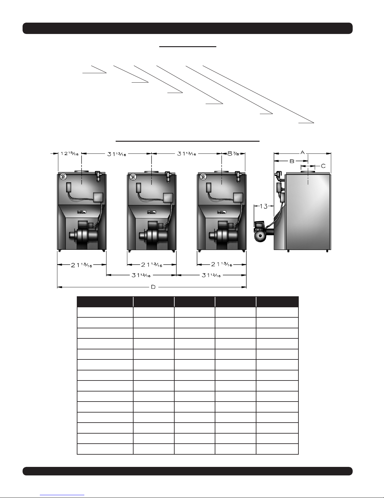
DIMENSIONS
MODEL # CODE
SF M 2 6 225 W
SERIES
MODULAR DESIGN
NO. OF PACKED BOILERS
SECTIONS PER BOILER
G.P.H. INPUT EACH FOR BOILER
TYPE OF UNIT
MULTIPLE BOILER DIMENSIONAL DATA
MODEL NO. A B C D
SFM6225W * 29 ¼” 13 ⅝” 8” ———
SFM7275W * 32 ⅞” 13 ⅝” 8” ———
SFM24150W 21 ½” 12 ⅝” 6” 53 13⁄16”
SFM25175W 25 ⅛” 14 ¼” 7” 53 13⁄16”
SFM25200W 25 ¼” 14 ¼” 7” 53 13⁄16”
SFM26225W 29 ¼” 13 ⅝” 8” 53 13⁄16”
SFM27275W 32 ⅞” 13 ⅝” 8” 53 13⁄16”
SFM36225W 29 ¼” 13 ⅝” 8” 85 7⁄16”
SFM37275W 32 ⅞” 13 ⅝” 8” 85 7⁄16”
SFM47275W 32 ⅞” 13 ⅝” 8” 87 13⁄16”
SFM57275W 32 ⅞” 13 ⅝” 8” 149 1⁄16”
SFM67275W 32 ⅞” 13 ⅝” 8” 181 13⁄16”
SFM77275W 32 ⅞” 13 ⅝” 8” 212 11⁄16”
SFM87275W 32 ⅞” 13 ⅝” 8” 245 ⅝”
* SFM6225W & SFM7275W are Single Module Units
4
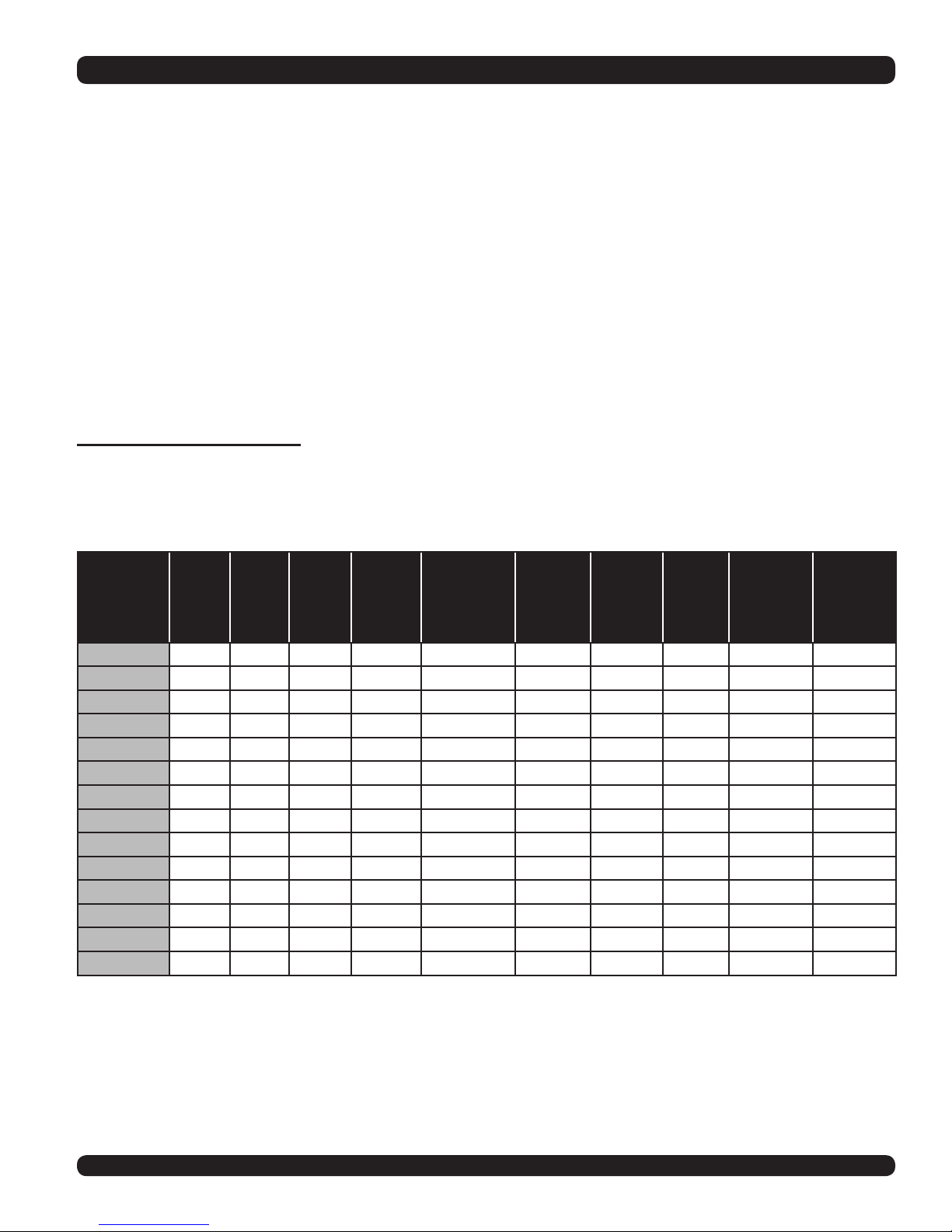
BOILER RATINGS, CAPACITIES & DIMENSIONS
NOTES:
1. Add sufx “T” to denote boiler with tankless heater.
2. I=B=R burner capacity is based on an oil heating value of 140,000 Btu/gal. and with 13% CO2.
3. For equivalent square feet of radiation, divide I=B=R output by 150.
4. Net ratings based on 170 0 F temperature in radiators and include 15% allowance for normal piping and pick-up load. Consult manufacturers for unusual piping and pick-up requirements.
5. Nozzle listed is for use with Beckett burner. When alternate burner is used, consult burner manufacturer’s recommendations.
6. Electrical service to be 120 Volts, 15 Amps, 60 Hz. (Each Boiler).
7. The MEA number for the SFM series is 182-86E.
8. The MEA number for the AFG burner is 213-83-E.
STANDARD EQUIPMENT: Crated Boiler, Flush Jacket, Oil Burner, Target Wall/Liner, ASME Relief Valve, Theralitimeter Gauge, Drain Cock, Wiring Harness, Burner Electrical Disconnect, Plastic
Cover, Supply Tapping - 2”, Return Tapping - 1 ¼”, High Limit and Circulator Control, Primary Control. For Tankless Heater Units-add Tankless Hot Water Coil.
TOTAL
FIRING
MODEL NO.
SFH6225W 2.25 315 254 221 SFM6225W 1 19.5 915 140 2.00 45B
SFH7275W 2.75 385 307 267.1 SFM7275W 1 22.5 1058 140 2.25 45B
SFM24150W 3.00 420 350 304 SFM4150W 2 27.0 1251 140 1.25 80B
SFM25175W 3.50 490 412 358 SFM5175W 2 33.0 1546 140 1.50 80B
SFM25200W 4.00 560 462 402 SFM5200W 2 33.0 1546 140 1.75 80B
SFM26225W 4.50 630 508 442 SFM6225W 2 39.0 1831 140 2.00 45B
SFM27275W 5.50 770 614 534.2 SFM7275W 2 45.0 2116 140 2.25 45B
SFM36225W 6.75 945 762 663 SFM6225W 3 58.5 2745 140 2.25 45B
SFM37275W 8.25 1155 921 801.3 SFM7275W 3 67.5 3174 140 2.25 45B
SFM47275W 11.00 1540 1228 1068.4 SFM7275W 4 90.0 4232 140 2.25 45B
SFM57275W 13.75 1925 1535 1335.5 SFM7275W 5 112.5 5290 140 2.25 45B
SFM67275W 16.50 2310 1842 1602.6 SFM7275W 6 135.0 6347 140 2.25 45B
SFM77275W 19.25 2695 2149 1869.7 SFM7275W 7 157.5 7905 140 2.25 45B
SFM87275W 22.00 3080 2456 2136.8 SFM7275W 8 180.0 8464 140 2.25 45B
RATE
G.P.H.
INPUT
M.B.H.
DOE
OUTPUT
M.B.H.
IBR
OUTPUT
M.B.H.
MODEL NO.
OF MODULES
NO. OF
MODULES
BOILER
WATER
VOLUME
GAL
BOILER
WEIGHT
LBS.
PUMP
PRESSURE
P.S.I
NOZZLE
FURNISHED
5
INTRODUCTION
All installations must conform to the requirements
of the authority having jurisdiction. Such applicable
requirements take precedence over the general
instructions of this manual.
Where required by the authority having jurisdiction, the installation must conform to the American
Society of Mechanical Engineers Safety Code for
Controls and Safety Devices for Automatically
Fired Boilers, ANSI/ASME No. CSD-1.
LOCATE BOILERS in front of nal position before
removing crate. Provide a level solid base as near
the chimney as possible, and centrally located
with respect to the heat distribution system as
practical.
WARNING
BOILER MAY NOT BE INSTALLED ON
COMBUSTIBLE FLOORING.
Allow 24 inches in the front and top for servicing and
cleaning, or removing tankless water heating coil.
When installed in a utility room, the door should
be wide enough to allow the largest boiler part to
enter, or to permit replacement of another appliance such as a water heater.
FOR INSTALLATION ON NON-COMBUSTIBLE
FLOORS ONLY. The boiler must not be installed
on carpeting or vinyl ooring. Minimum clearances
to combustible construction are:
TOP .............................................24 IN.
FRONT ........................................24 IN.
FLUE CONNECTOR .....................9 IN.
REAR ............................................6 IN.
SIDES .........................................12 IN.
NOTE: Clearance for access should exceed
fore protection clearance.
REMOVE CRATE and plastic protective wrapper
and inspect for damage. All equipment is carefully
manufactured, inspected and packaged by experienced workers. Our responsibility ceases upon
delivery of the crated boiler to the carrier in good
condition. Any claims for damage or shortage in
shipment must be led immediately against the
carrier by the cosigner. Move boiler to permanent
position by sliding or walking.
6
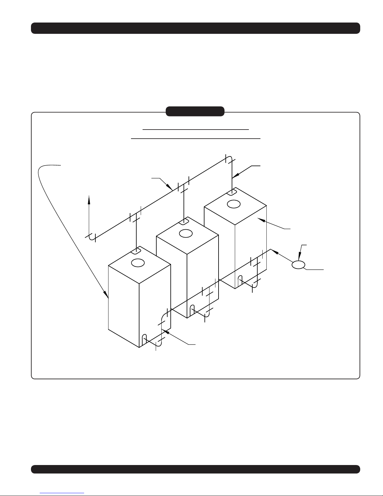
RETURN
SUPPLY
CIRCULATOR
REAR OF BOILER
FRONT OF BOILER
BRANCH
BRANCH
MAIN
CONNECTING SUPPLY AND RETURN PIPING
The recommended method of connecting the supply and return piping can be seen in
Figure #1 below.
(For detailed piping recommendations refer to the engineering manual)
Figure #1
MODULAR BOILER HOOK-UP
RECOMMENDED PARALLEL PIPING
7
ZONE 1
ZONE2
ZONE 3
REAR OF
BOILER
BRANCH
BRANCH
12"
MAX
FRONT OF
BOILER
AIR
ELIMINATOR &
EXPANSION
TANK
PRIMARY
PUMP
PRIMARY
LOOP
SECONDARY
PUMP
LOAD
PUMPS
TO
EXPANSION
TANK &
SYSTEM
FILL
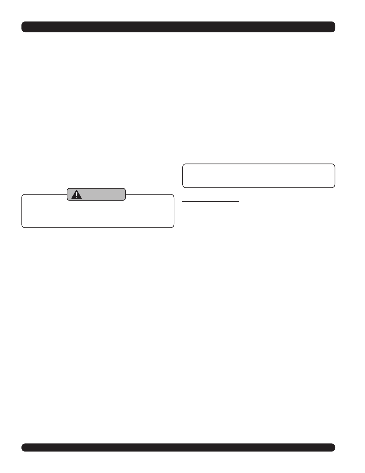
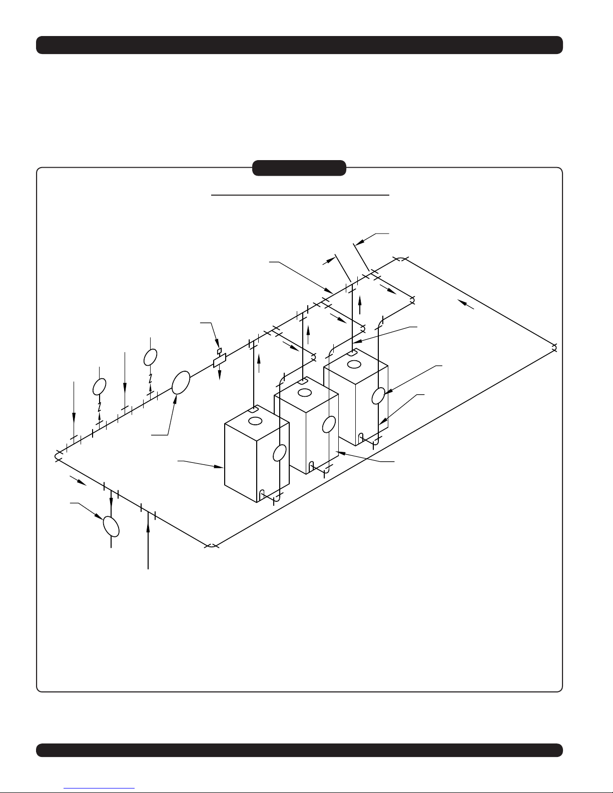
PRIMARY SECONDARY PIPING
An alternate method of connecting the supply and return piping can be seen in Figure #2
below.
(Refer to the engineering manual for detailed piping recommendations.)
Figure #2
PRIMARY SECONDARY PIPING
Note: The tapping sizes for the supply and return piping are 2” and 1 ½” respectively.
It is recommended that the main piping be 3” and the branches 1 ½”.
8
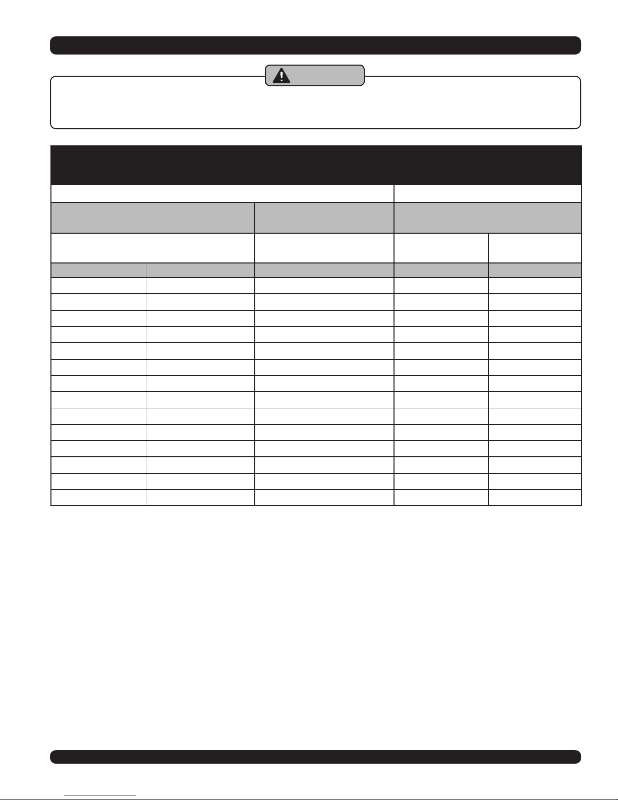
VENTILATION & COMBUSTION AIR
WARNING
AIR OPENINGS TO COMBUSTION AREA MUST NOT BE OBSTRUCTED. FOLLOW THE CHART
BELOW TO OBTAIN AND MAINTAIN ADEQUATE COMBUSTION AIR.
COMBUSTION AIR REQUIRMENTS
(MINIMUM OPENING IN SQUARE INCHES)
*UNCONFINED AREA **CONFINED AREA
OUTSIDE
COMBUSTION AIR
1 IN2/5000BTU
(PARAGRAPH 2)(SQ IN)
BTU/HR INPUT
COMBUSTION AIR
(MIN 100IN2) (FIG 4) (SQ IN)
315,000 63 315 78.75 158
385,000 77 385 96.25 193
420,000 84 420 105 210
490,000 98 490 123 245
560,000 112 560 140 280
630,000 126 630 158 315
770,000 154 770 193 385
945,000 189 945 237 473
1,155,000 231 1155 289 578
1,540,000 308 1540 385 770
1,925,000 385 1925 482 963
2,310,000 462 2310 578 1155
2,695,000 539 2695 675 1348
3,080,000 616 3080 770 1540
* Unconned area: A space whose volume is not less than 50 cubic feet per 1000 BTU per hour of all appliances in-
stalled in that space (cubic feet of space = height x width x length).
** Conned area: A space whose volume is less than 50 cubic feet per 1000 BTU per hour of all appliances installed in
that space (cubic feet of space = height x width x length).
INSIDE
1 IN2/1000 BTU
OUTSIDE
COMBUSTION AIR
1 IN2/4000 BTU
(FIG 3)(SQ IN)
1 IN2/2000 BTU
(FIG 3)(SQ IN)
1. When a boiler is located in an unconned
space in a building of conventional construction
frame, masonry or metal, inltration normally
is adequate to provide air for combustion and
ventilation. However, in any building which
has been altered to conserve energy or to
minimize inltration, the boiler area should
be considered as a CONFINED SPACE. If
there is any doubt, install air supply provisions
for combustion and ventilation in accordance
with section 5.3, Air for Combustion and Ventila-
tion, of the latest revision of the NFPA 54 code,
the recommendations that follow, or applicable
provisions of the local building codes.
2. When a boiler is installed in an unconned space,
in a building of unusually tight construction, air
for combustion and room ventilation must be
obtained from outdoors or from spaces freely
communicating with the outdoors. A permanent
opening or openings having a total free area
of not less than 1 square inch per 5,000 BTU
per hour of total input rating of all appliances
9
 Loading...