

UTICA BOILERS MGC-8D, MGC-9D, MGC-9DP, MGC-8DP Installation, Operation And Maintenance Manual
Models
MGC-8D
MGC-8DP
MGC-9D
MGC
GAS-FIRED
HOT WATER BOILERS
INSTALLATION, OPERATION &
MGC-9DP
MAINTENANCE MANUAL
C.S.A. Certied for
Natural gas or
Propane
Tested for 50 psi.
ASME Working
Pressure
Manufactured by:
ECR International, Inc.
2201 Dwyer Avenue, Utica NY 13501
web site: www.ecrinternational.com
P/N 240011125, Rev. C [07/22/2015]
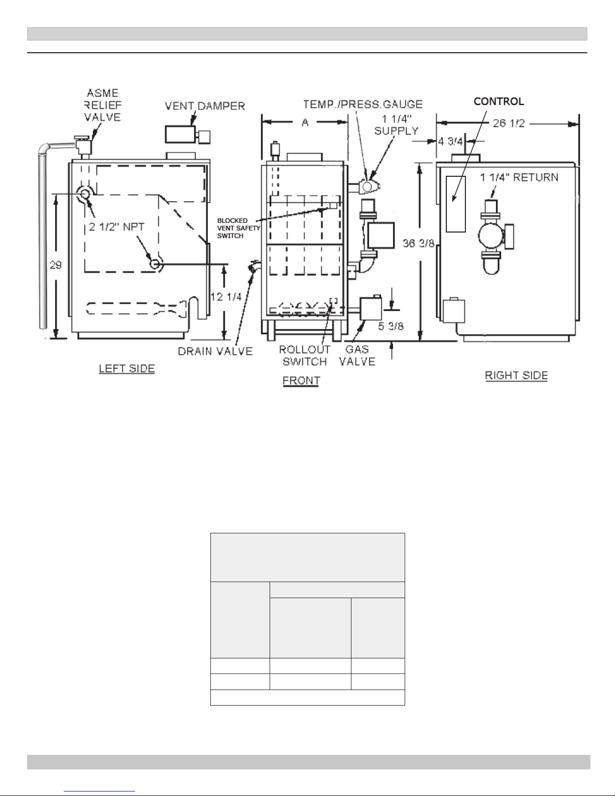
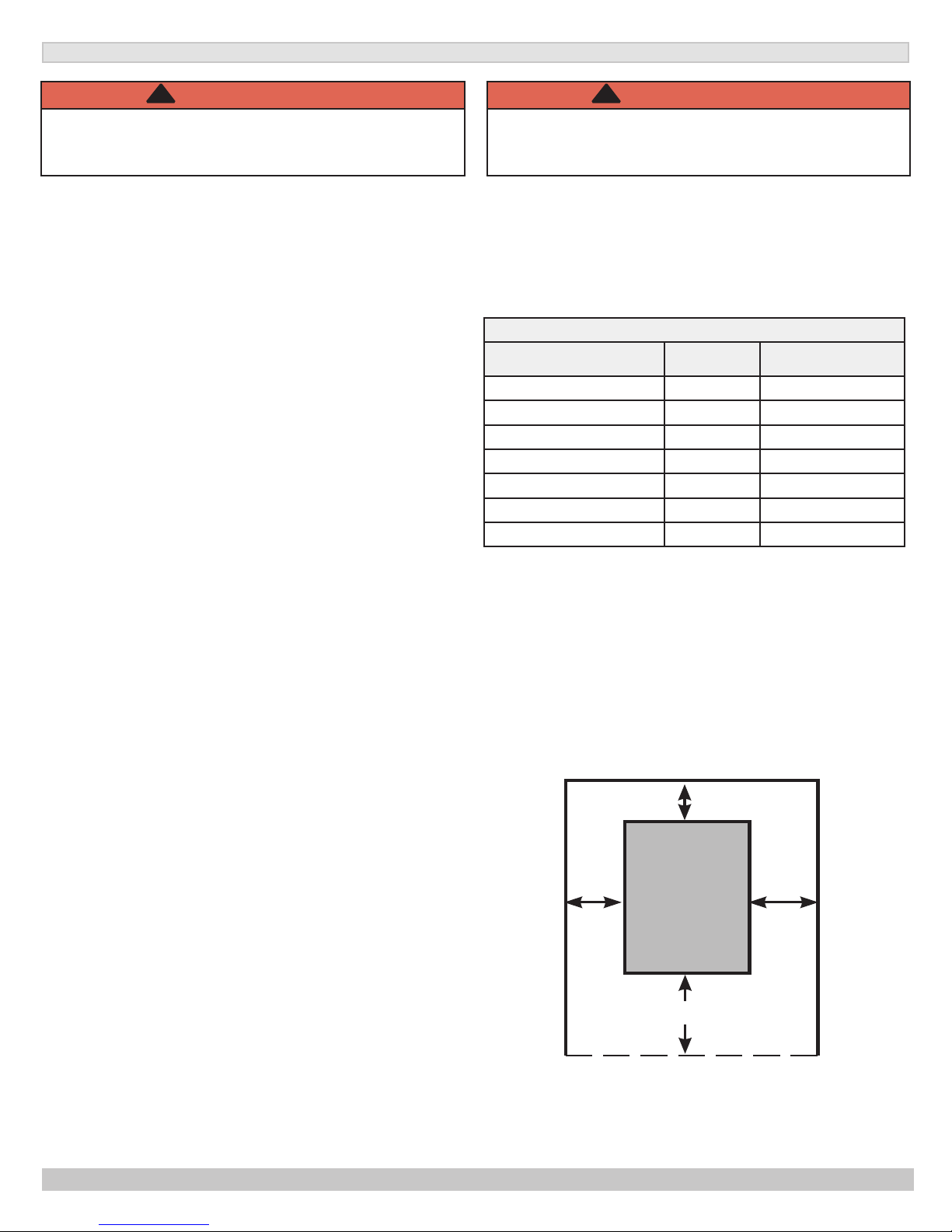
Figure 1 - Dimensions
1 - DIMENSIONS
*
* Minimum acceptable height for Low Water Cutoff probe.
Table 1 - Dimensions
DIMENSIONS (INCH.)
BOILER
MODEL
NUMBER
MGC-8 7 27½
MGC-9 7 30¾
Add 5½” to height for vent Damper.
FLUE
DIAMETER
“A”
WIDTH
2
P/N 240011125, Rev. C [07/22/2015]
2 - BOILER RATINGS AND CAPACITIES
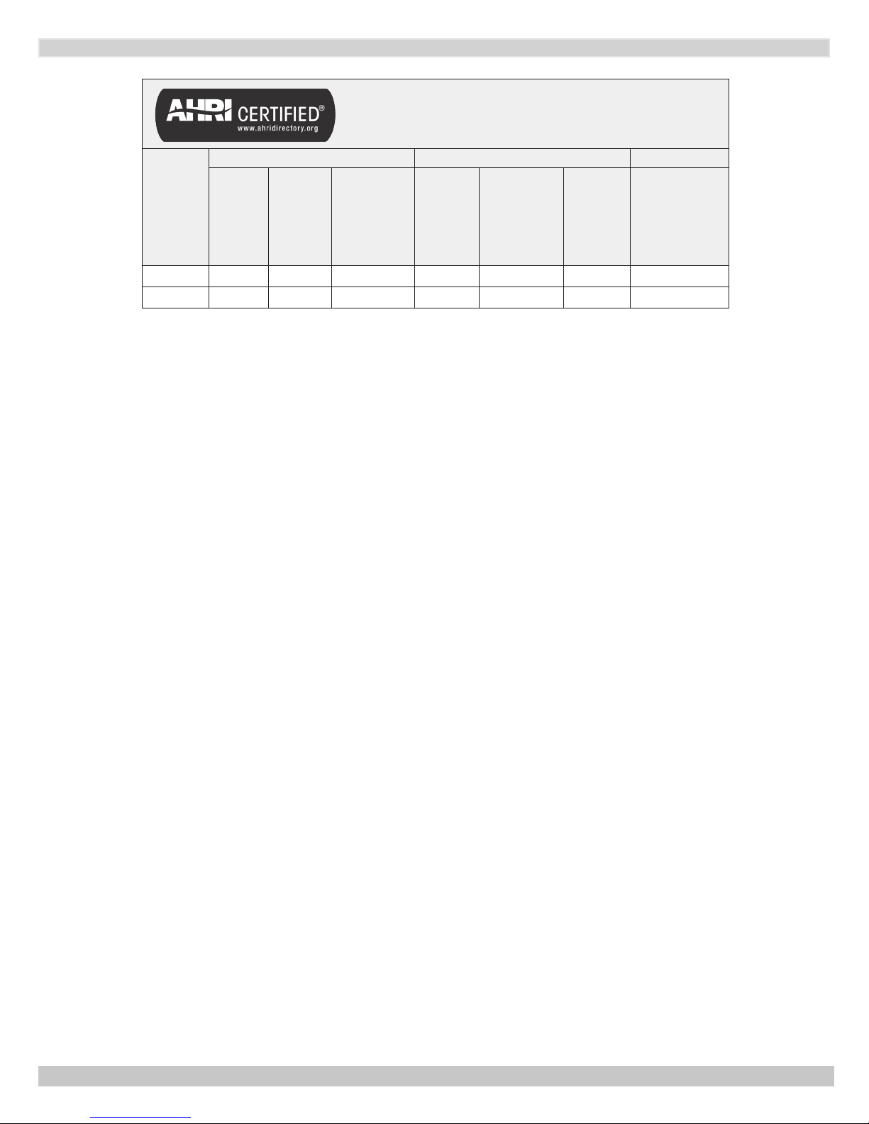
Table 2 - Ratings and Capacities
† NATURAL GAS † PROPANE GAS AFUE
(2)
BOILER
MODEL
NUMBER
(1)
Input
Mbh
(3)
(1)
Heating
Capacity
(3)
Mbh
MGC-8 262.5 220 191 245 206 179 83.9
MGC-9 299 251 218 280 235 204 83.7
†
Input rating for sea level to 2,000 ft. (610m) above sea level. Over 2000 ft (610m) above sea level.
Reduce input rate 4% for every 1000 ft (304m) above sea level.
+ Heating Capacity based on D.O.E. (Department of Energy) test procedure.
(1)
Add model number sufce ‘P’ for Propane.
(2)
Net AHRI Water rating shown based on piping and pickup allowance of 1.15. Consult manufacturer before selecting
boiler for installations having unusual piping and pickup requirements, such as intermittent system operation,
extensive piping systems, etc.
(3)
MBH = 1,000 Btuh = British Thermal Unit Per Hour
NET AHRI
RATING
Water,
(3)
Mbh
INPUT
MBH
(3)
HEATING
CAPACITY
MBH
(3)
NET AHRI
RATING
INTERMITTENT
IGNITION WITH
VENT DAMPER
Ratings marked “Net AHRI Ratings” indicate amount of remaining heat input used to heat radiation or terminal units. Net
AHRI Ratings shown are based on allowance of 1.15 in accordance with factors shown on AHRI Standard as published by
The Hydronics Institute.
- Selection of boiler size should be based upon “Net AHRI Rating” being equal to or greater than calculated heat loss of
the building.
- Consult manufacturer before selecting boiler for installations having unusual piping and pickup requirements.
BOILERS FOR USE AT HIGH ALTITUDE
Boiler is factory equipped for use at altitudes of 0-2,000 feet above sea level.
For use at altitudes above 2,000 feet above sea level, input ratings are reduced by change in main burner orice size.
For altitudes above 2,000 feet above sea level, input ratings should be reduced at rate of 4% for each 1,000 feet above
sea level. Consult National Fuel Gas Code, ANSI Z223.1/NFPA 54 or manufacturer for correct orice sizing information.
3
P/N 240011125, Rev. C [07/22/2015]
3 - TABLE OF CONTENTS
1 - Dimensions ................................................... 2
2 - Ratings And Capacities ................................... 3
3 - Table of Contents ........................................... 4
4 - Installation Procedure .................................... 5
5 - Ventilation & Combustion Air ........................... 6
6 - Connecting Supply And Return Piping ............... 7
7 - Chimney And Vent Pipe Connection .................11
8 - Vent Damper Operation .................................14
9 - Gas Supply Piping .........................................15
10 - Electrical Wiring ..........................................15
11 - Wiring Diagrams .........................................16
12 - General Instructions ....................................19
13 - Lighting Instructions ...................................20
14 - Operating Your Boiler ..................................21
15 - Maintaining Your Boiler ................................23
16 - Service Hints ..............................................24
17 - Equipment And Optional Accessories ............25
Appendix A - Control Module ...............................27
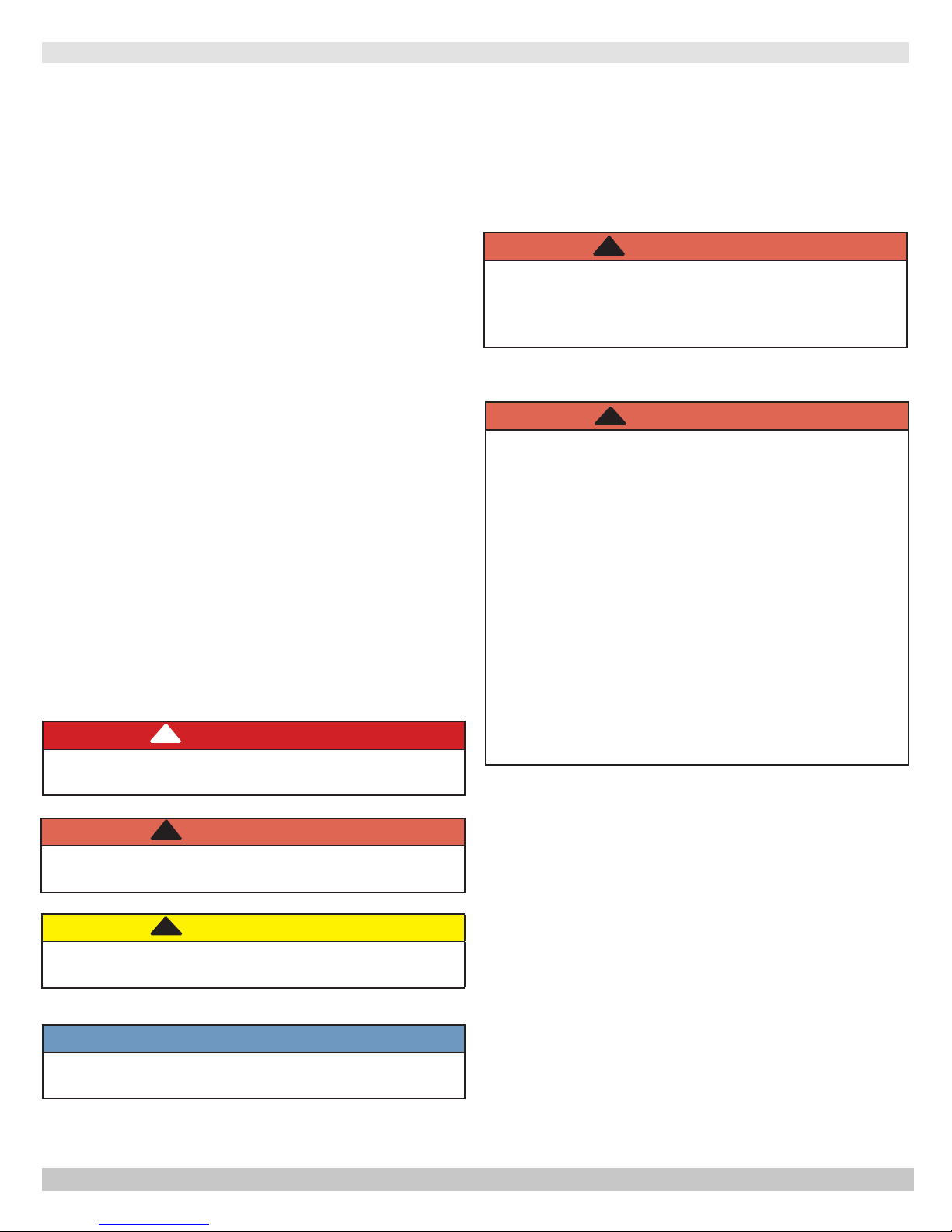
SAFETY SYMBOLS & WARNINGS
The following dened symbols are used throughout this
manual to notify the reader of potential hazards of varying
risk levels.
!
DANGER
Indicates a hazardous situation which, if not avoided,
WILL result in death or serious injury
KEEP THIS MANUAL NEAR BOILER
RETAIN FOR FUTURE REFERENCE
IMPORTANT: Read the following instructions
COMPLETELY before installing!!
WARNING
!
Fire, explosion, asphyxiation and electrical shock
hazard. Improper installation could result in death
or serious injury. Read this manual and understand
all requirements before beginning installation.
WARNING
!
Keep boiler area clear and free from combustible
materials, gasoline and other ammable vapors
and liquids.
DO NOT obstruct air openings to the boiler room.
Modication, substitution or elimination of factory
equipped, supplied or specied components may
result in personal injury or loss of life.
TO THE OWNER - Installation and service of this
boiler must be performed by a qualied installer.
TO THE INSTALLER - Leave all instructions with
boiler for future reference.
When this product is installed in the
Commonwealth of Massachusetts the installation
must be performed by a Licensed Plumber or
Licensed Gas Fitter.
!
WARNING
Indicates a hazardous situation which, if not avoided,
could result in death or serious injury.
!
CAUTION
Indicates a hazardous situation which, if not avoided,
could result in minor or moderate injury.
NOTICE
Used to address practices not related to personal
injury.
4
P/N 240011125, Rev. C [07/22/2015]
4 - INSTALLATION PROCEDURE
!
WARNING
Improper installation, adjustment, alteration,
service or maintenance could result in death or
serious injury.
1.
Installation must conform to the requirements of the
authority having jurisdiction or, in the absence of such
requirements, to the National Fuel Gas Code, ANSI
Z223.1/NFPA 54, and/or Natural Gas and Propane
Installation Code, CAN/CSA B149.1.
2.
Where required by the authority having jurisdiction, the
installation must conform to the Standard for Controls
and Safety Devices for Automatically red Boilers,
ANSI/ASME CSD-1.
3.
Boiler series is classied as a Category I. Vent
installation shall be in accordance with "Venting of
Equipment ," of the National Fuel Gas Code, ANSI
Z223.1/NFPA 54, or "Venting Systems and Air Supply
for Appliances," of the Natural Gas and Propane
Installation Code, CAN/CSA B149.1, or applicable
provisions of the local building codes.
4.
Boiler has met safe lighting and other performance
criteria with the gas manifold and control assembly on
the boiler per the latest revision of ANSI Z21.13/CGA
4.9.
5.
Install boiler such that gas ignition system components
are protected from water (dripping, spraying, rain,
etc.) during appliance operation and service, (circulator
replacement, condensate trap, control replacement,
etc.).
6.
Locate boiler on level, solid base as near chimney as
possible and centrally located with respect to heat
distribution system as practical.
7.
Allow 24 inches (610mm ) at front and right side for
servicing and cleaning.
8.
When installed in utility room, door should be wide
enough to allow largest boiler part to enter, or to
permit replacement of another appliance such as water
heater.
!
WARNING
Fire hazard. Do not install boiler on combustible
ooring or carpeting. Failure to follow these
instructions could result in death or serious injury.
1.
FOR INSTALLATION ON NON-COMBUSTIBLE
FLOORS ONLY - For installation on combustible
ooring special base must be used. (See Replacement
Parts Section.) Boiler shall not be installed on
carpeting.
Table 3 -
Top 6”
Rear 6”
Control Side 7” (178mm)
Opposite Side 6” (152mm)
Front
Flue/Vent Connector 6” (152mm)
Near Boiler Piping 1/2” (13mm)
NOTE: Greater clearances for access should supersede fire
* Denition of Alcove is three sided space with no wall in
front of boiler. ANSI standard for alcove is 18 inches from
front of appliance to leading edge of side walls as shown
below.
MINIMUM CLEARANCE DIMENSIONS
Inches (mm)
(152mm)
(152mm)
18” (457mm)
protection clearances.
Minimum Clearances to Combustible
Construction (as seen from above)
6"
6"
BOILER
7"
Control
Side
Front
18"
5
P/N 240011125, Rev. C [07/22/2015]

5 - VENTILATION & COMBUSTION AIR
Provide combustion air and ventilation air in accordance
with the section “Air for Combustion and Ventilation,” of the
National Fuel Gas Code, ANSI Z223.1/NFPA 54, or Sections
8.2, 8.3 or 8.4 of Natural Gas and Propane Installation
Code, CAN/CSA B149.1, or applicable provisions of local
building codes.
Provide make-up air where exhaust fans, clothes dryers,
and kitchen ventilation equipment interfere with proper
operation.
National Fuel Gas Code recognizes several methods
of obtaining adequate ventilation and combustion air.
Requirements of the authority having jurisdiction may
override these methods.
• Engineered Installations. Must be approved by
authority having jurisdiction.
• Mechanical Air Supply. Provide minimum of 0.35
cfm per Mbh for all appliances located within space.
Additional requirements where exhaust fans installed.
Interlock each appliance to mechanical air supply
system to prevent main burner operation when
mechanical air supply system not operating.
• All Indoor Air. Calculate minimum allowable room
volume for all appliances in space. Use a different
method if minimum volume not available.
A. Standard Method. Cannot be used if known air
inltration rate is less than 0.40 air changes per
hour. See Table 4 for space with boiler only. Use
equation for multiple appliances.
Volume ≥ 50 ft3 x Total Input [Mbh]
B. Known Air Inltration Rate. See Table 4 for
space with boiler only. Use equation for multiple
appliances. Do not use an air inltration rate
(ACH) greater than 0.60.
Volume ≥ 21 ft3⁄ACH x Total Input [Mbh]
C. Refer to National Fuel Gas Code for opening
requirements between connected indoor spaces.
Canada
National Gas and Propane Installation Code Requires
providing air supply in accordance with:
• All Outdoor Air. Provide permanent opening(s)
communicating directly or by ducts with outdoors.
A. Two Permanent Opening Method. Provide opening
commencing within 12 inches of top and second
opening commencing within 12 inches of bottom of
enclosure.
Direct communication with outdoors or
communicating through vertical ducts. Provide
minimum free area of 1 in² per 4 Mbh of total
input rating of all appliances in enclosure.
Communicating through horizontal ducts.
Provide minimum free area of 1 in² per 2
Mbh of total input rating of all appliances in
enclosure.
B. One Permanent Opening Method. Provide opening
commencing within 12 inches of top of enclosure.
Provide minimum clearance of 1 inch on sides/back
and 6 inches on front of boiler (does not supersede
clearance to combustible materials).
• Refer to National Fuel Gas Code for additional
requirements for louvers, grilles, screens and air
ducts.
• Combination Indoor and Outdoor Air. Refer to National
Fuel Gas Code for application information.
• Section 8.2 and 8.3 when combination of appliances
has a total input of up to and including 400 Mbh (120
kW).
• Section 8.4 when combination of appliances has total
input exceeding 400 Mbh (120 kW).
• Refer to Natural Gas and Propane Installation Code
for specic air supply requirements for enclosure
or structure where boiler is installed, including air
supply openings and ducts.
Table 4 - Minimum Room Volume, Indoor Air Only*
Input Mbh
Standard
Method
0.1 0.2 0.3 0.4 0.5 0.6
262.5 13125 55125 27563 18375 13781 11025 9188
299 14950 62790 31395 20930 15698 12558 10465
* Table values based on boiler only. Add volume for any additional appliances.
Room Cubic Feet Volume
Known Air Inltration Rate Method (Air Changes Per Hour)
6
P/N 240011125, Rev. C [07/22/2015]
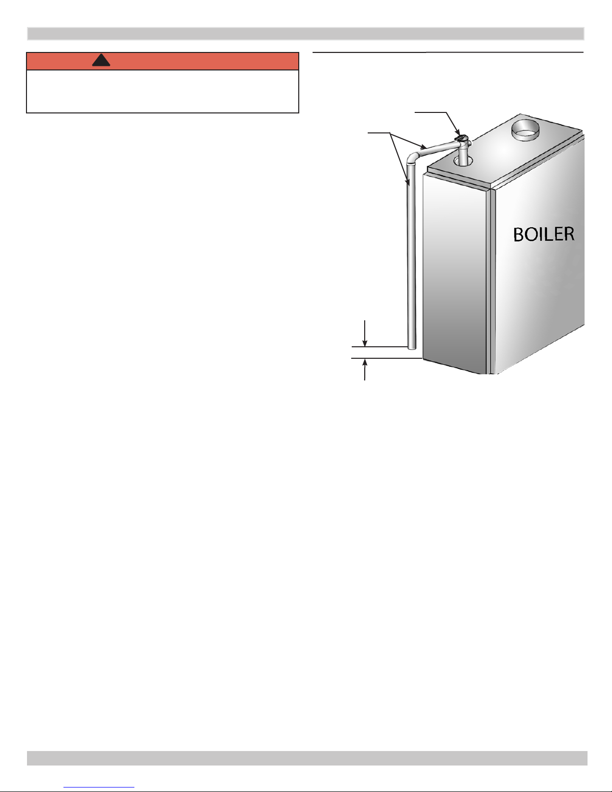
6 - CONNECTING SUPPLY AND RETURN PIPING
!
WARNING
Burn and scald hazard. Safety relief valve could
discharge steam or hot water during operation.
Install discharge piping per these instructions.
Figure 2 - Safety Relief Valve
RELIEF VALVE
1.
Refer to local codes and appropriate ASME Boiler
and Pressure Vessel Code for additional installation
requirements. Install safety relief valve using pipe
ttings provided with boiler. See Figure 2
2.
Install safety relief valve with spindle in vertical
position.
3.
Do not install shutoff valve between boiler and safety
relief valve.
4.
Install discharge piping from safety relief valve. See
Figure 2.
• Use ¾” or larger pipe.
• Use pipe suitable for temperatures of 375°F (191°C)
or greater.
• Individual boiler discharge piping shall be independent
of other discharge piping.
• Size and arrange discharge piping to avoid reducing
safety relief valve relieving capacity below minimum
relief valve capacity stated on rating plate.
• Run pipe as short and straight as possible to location
protecting user from scalding and properly drain
piping.
DISCHARGE
LINE
Check local
codes for
maximum
distance
from oor
or allowable
safe point of
discharge.
• Install union, if used, close to safety relief valve outlet.
• Install elbow(s), if used, close to safety relief valve
outlet and downstream of union (if used).
• Terminate pipe with plain end (not threaded).
7
P/N 240011125, Rev. C [07/22/2015]
6 - CONNECTING SUPPLY AND RETURN PIPING
!
WARNING
Burn and scald hazard. Safety relief valve could
discharge steam or hot water during operation.
Install discharge piping per these instructions.
1.
Boiler is shipped assembled. Install discharge piping
from safety relief valve. See Warning, Page 7.
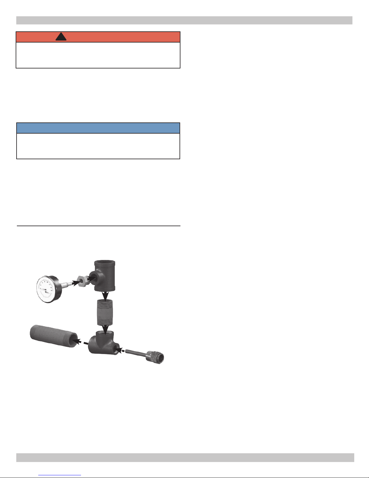
2.
Install temperature pressure gauge.
• Apply pipe sealant to threads on shaft of gauge.
• Thread gauge into supply water tee. See Figure 3.
NOTICE
DO NOT TIGHTEN GAUGE BY HAND!! Gauge should
be tightened using crescent wrench or 9/16” open
end wrench. See Figure 3.
3.
Connect supply and return lines to boiler. Connections
may require additional ttings and parts, as shown on
diagrams.
Verify clean water supply is available to water inlet valve.
Install sand strainer when water supply is from a well or
pump.
Install hot water boiler above radiation level or as
required by Authority having jurisdiction install low
water cutoff device at time of installation. See Figure 1
for minimum probe height. Use kit #550002998. follow
instruction enclosed with kit. With other LWCO’s use their
manufacturer specic instructions.
Periodic inspection is necessary, as is ushing of oat type
devices, per manufacturers specic instruction.
FOR USE WITH COOLING UNITS
A. Boiler used in connection with refrigeration system, must
be installed so that chilled medium is piped in parallel
with heating boiler. Appropriate valves must be used to
prevent chilled medium from entering heating boiler. See
Figure 5 page 9.
B. Boiler connected to heating coils located in air handling
units where they may be exposed to refrigerated air
circulation, piping system shall be equipped with ow
control valves or other automatic means to prevent
gravity circulation of boiler water during cooling cycle.
Figure 3 - Temperature Pressure Gauge
LOW WATER TEMPERATURE AND LARGE WATER
CONTENT SYSTEM (See Figures 6 and 7, Page 10.)
Signicant condensation may form in boiler and/or venting
system if boiler is operated for long period of time with
return temperatures of less than 120° F.
Condensate is corrosive and can cause severe damage to
boiler and venting system. Minimum design return water
temperature to prevent condensation in boiler and venting
is 120°F. Minimum high limit setting is 140°F.
1.
Boiler used in heating system where design water
temperatures below 140°F are desired (e.g. radiant
oor heating), 4-way mixing valve or suitable
alternative is required to prevent low temperature
return water from entering boiler. Follow mixing valve
manufacturer’s instructions.
2.
Boiler connected to system having large water content
(such as former gravity system), install system bypass.
See Figures 6 and 7, page 10.
3.
If boiler water reset control is used to operate boiler,
minimum reset supply water temperature setpoint
must be at least 140°F, unless mixing valve is used as
in (1) above.
8
P/N 240011125, Rev. C [07/22/2015]
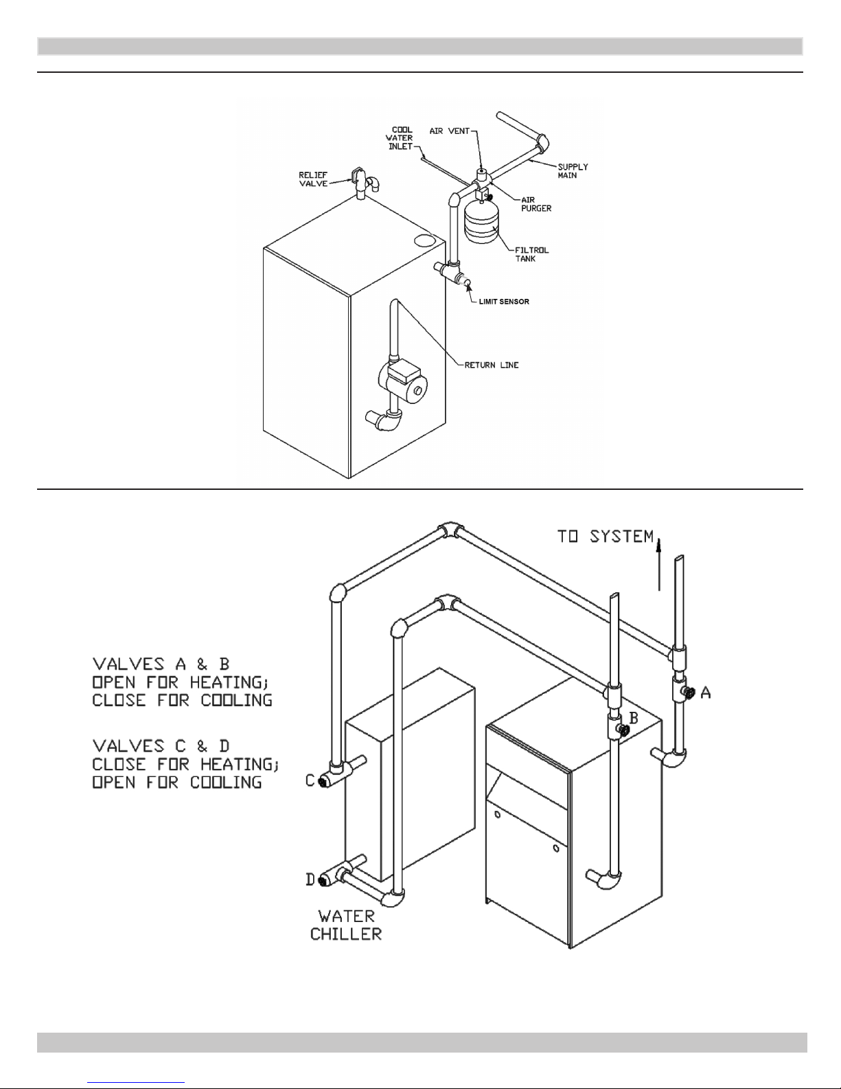
6 - CONNECTING SUPPLY AND RETURN PIPING
Figure 4 - Typical Hot Water Piping
Figure 5 - Chilled Water Piping
9
P/N 240011125, Rev. C [07/22/2015]
6 - CONNECTING SUPPLY AND RETURN PIPING
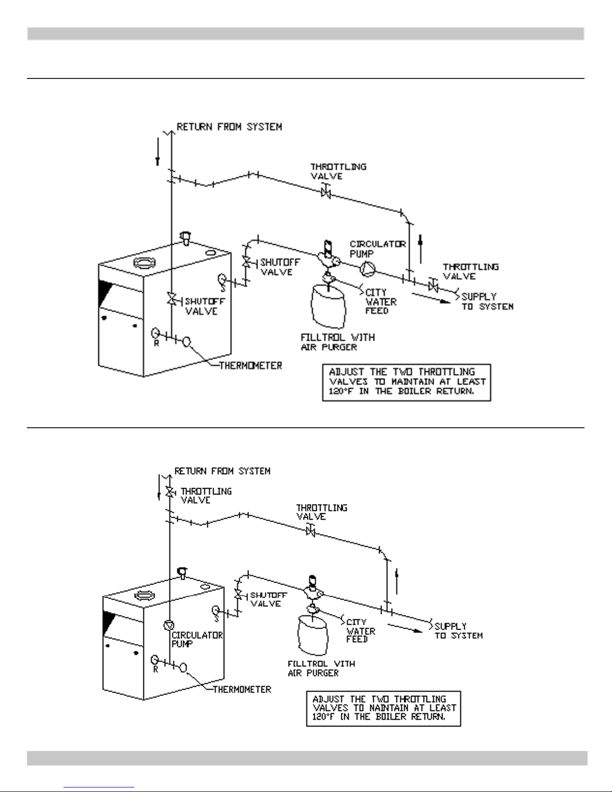
Bypass Piping Required For High Mass (Large Water Content) Systems
Figure 6 - BYPASS PIPING - CIRCULATOR ON SUPPLY
Figure 7 - BYPASS PIPING - CIRCULATOR ON RETURN
10
P/N 240011125, Rev. C [07/22/2015]
 Loading...