

UTICA BOILERS MGB75, MGB100, MGB125, MGB150, MGB175 Installation, Operation & Maintanance Manual
...
P/N 37611601, Rev. B [02/09]
R
An I SO 9001 -2000 Ce rtifie d Company
MGB SERIES
Cast Iron Gas Fired Boilers
For Forced Hot Water
INSTALLATION, OPERATION &
MAINTANANCE MANUAL
UTICA BOILERS
P.O. Box 4729
Utica, NY 13504-4729
MEMBER: The Hydronics Institute
MODEL NUMBERS:
MGB50 MGB75 MGB100
MGB125 MGB150 MGB175
MGB200 MGB250 MGB300
National Excelsior Company
www.excelsiorhvac.com
Subject to change without notice.

INSTALLATION MANUAL AND OPERATING INSTRUCTIONS
H
National Excelsior Company
www.excelsiorhvac.com
Subject to change without notice.
TABLE OF CONTENTS
Ratings & Data - Natural Gas & Propane Gas ... 3
Installation Procedure .........................................4
Ventilation & Combustion Air ..............................5
IMPORTANT: Read the following instruc-
tions COMPLETELY before installing!!
Connecting Supply & Return Piping ...................7
Vent Installation ................................................ 11
Vent System Modification ................................. 11
Vent Damper Installation & Instructions............ 12
Connecting Gas Service ...................................13
Electrical Section ..............................................13
Wiring Diagram - 24V Standing Pilot ................14
Wiring Diagram - Intermittent Ignition ...............15
Lighting Instructions..........................................16
Normal Sequence of Operation ........................18
General Instructions ......................................... 18
Checking Gas Input Rate To Boiler .................. 20
Replacement Parts......................................22-27
KEEP THIS MANUAL NEAR BOILER
RETAIN FOR FUTURE REFERENCE
SAFETY SYMBOLS & WARNINGS
WARNING
!
1. Keep boiler area clear and free from combustible
materials, gasoline and other flammable vapors
and liquids.
2. DO NOT obstruct air openings to the boiler
room.
3. Modification, substitution or elimination of factory equipped, supplied or specified components
may result in property damage, personal injury or
the loss of life.
4. TO THE OWNER - Installation and service of this
boiler must be performed by a qualified installer.
5. TO THE INSTALLER - Leave all instructions with
the boiler for future reference.
6. When this product is installed in the Commonwealth of Massachusetts the installation must be
performed by a Licensed Plumber or Licensed
Gas Fitter.
The following defined symbols are used throughout this manual
to notify the reader of potential hazards of varying risk levels.
DANGER
!
Indicates an imminently hazardous situation
Which, if not avoided, will result in death, serious
injury or substantial property damage.
WARNING
!
Indicates a potentially hazardous situation which,
if not avoided, could result in death, serious injury
or substantial property damage.
CAUTION
!
Indicates a potentially hazardous situation which,
if not avoided, could result in minor or moderate
injury or property damage.
WARNING
!
All installations of boilers and venting should be
done only by a qualified expert and in accordance
with the appropriate manual. Installing or venting
a boiler or any other gas appliance with improper
methods or materials may result in serious injury or
death due to fire or to asphyxiation from poisonous
gases such as carbon monoxide which is odorless
and invisible.
C.S.A. Certified
For Natural Gas Or Propane
2
Tested For 100 LBS.
ASME
Working Pressure
RATINGS & DATA - NATURAL GAS & PROPANE GAS
National Excelsior Company
www.excelsiorhvac.com
Subject to change without notice.
(1) **
I
=B=R
NetOutput
Btu/Hr
37,000 243
55,000 365
72,000 481
Boiler
No.
(1)
A
.G.
Btu/Hr.
50 50,000
75 75,000
100 100,000
A
.
I
nput
(1)
Heating
C
apacity Btu/Hr.
42,000
63,000
83,000
125 125,000 104,000 90,000 603
150 150,000 124,000 108,000
175 175,000 143,000 124,000 829
200 200,000 165,000 143,000 957
250 250,000 205,000 178,000
300 299,999 243,000 214,000 1368
EXPLANATORY NOTES
--All boilers are design certified for installation on noncombustible floor.
--For installation on combustible floors use combustible floor kit.
--Recommended chimney height 20 feet. In special cases where conditions
permit, chimney height may be reduced to 10 feet. Refer to the latest
revision of NFGC part 11.
--Electric service to be 120 Volts, 15 Amps, 60 Hz.
--The MEA number for the this boiler is 19-79-E.
(1) For elevations above 2000 feet, ratings should be
reduced at a rate of 4% for each 1000 feet above sea
level.
(2) Base on 170° temperature in radiators.
(3) Tank sized for non-ferrous baseboard or radiant panel
systems. Increase size for cast iron baseboard and
radiation.
--Net I=B=R ratings include 15% allowance for normal
piping and pick-up load. Manufacturer should be
consulted on installations having other than normal piping
and pick-up requirements.
** For equivalent square feet of radiation, divide I=B=R
output by 150.
STANDARD EQUIPMENT: Boiler Jacket, Cast Iron Boiler
Battery, High Limit Control, Vent Damper Relay, Theraltimeter
Gauge, Circulator With Return Piping To Boiler, Main Gas
Burners, Combination 24 Volt Gas Control (Includes Automatic
Gas Valve, Gas Pressure Regulator, Automatic Pilot, Safety
Shutoff, Pilot Flow Adjustment, Pilot Filter), A.S.M.E. Relief
Valve, Drain Cock, Spill Switch, Rollout Switch, Automatic Vent
Damper. Not Shown Are: Wiring Harness, Thermocouple,
Non-linting Safety Pilot.
OPTIONAL EQUIPMENT: Intermittent Electric Ignition
Pilot System.
(2)
NetRating
Sq. Ft. HW
@ 170
o
719
1189
No.
of
Burners
1
2
2
3
3
4
4
5
6
(3)
Recommended
A
ir
C
ushion
T
ank
15 2.4
15
30 4.0
30 5.6
30 5.6
30 7.2
30 7.2
30
60 10.4
Water
C
ontent
(Gals.)
4.0
8.8
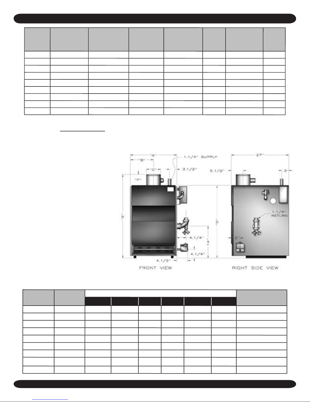
Boiler No.
50
75
100
125
150
175
Natural Gas
I
nlet*
½"
A
11⅛"
½" 15 7
½" 15 7
½"
½"
18⅞"
18⅞"
½" 22¾
200 ½" 22¾" 11 ½" 8" 30¾" 38¾" 8" 1¼"
250 ¾"
265
13
300 ¾" 30½" 15¼" 9" 30¾" 42¾" 10" 1¼"
* Propane gas inlet, all units, 1/2"
" 11
⁄
"
16
Dimensions
B
5
½
" 4" 30¾" 36¼" 6"
½
" 5" 30¾" 37¾" 6"
½
" 6" 30¾" 37¼" 6½"
9
½
" 6" 30¾" 37¼" 6½"
9
½
" 7" 30¾" 37¾" 7"
½
" 7" 30¾" 38¾" 7" 1¼"
C DE
F
Pump size Supply &
Return
13¼" 8" 30¾" 40¾" 8"
3
T
appings
1¼"
1¼"
1¼"
1¼"
1¼"
1¼"

INSTALLATION PROCEDURE
National Excelsior Company
www.excelsiorhvac.com
Subject to change without notice.
WARNING
!
Improper installation, adjustment, alteration, service or maintenance can cause
injury or property damage.
The installation must conform to the requirements of the
1.
authority having jurisdiction or, in the absence of such
requirements, to the latest revision of the National Fuel
Gas Code, ANSI Z223. (Available from the American Gas
Association, 8501 E. Pleasant Valley Road, Cleveland,
Ohio 44134). Reference should also be made to local gas
utility regulations and other codes in effect in the area
in which the installation is to be made. When installed
in Canada: The latest revision of the CAN1-B149.1 and/
or B149.2 Installation Codes for Gas-Burning Equipment
and/or local codes.
2.
Where required by the authority having jurisdiction, the
installation must conform to American Society of Mechanical Engineers Safety Code for Controls and Safety
Devices For Automatically Fired Boilers, ANSI/ASME
No.CSD-1.
3.
This boiler series is classified as a Category 1 and the
vent installation shall be in accordance with Part 7 of the
National Fuel Gas Code noted above when installed in
the United States. In Canada refer to the CAN1-B149.1
and or B149.2 Installation Codes for Gas-Burning Equipment. Also refer to applicable provisions of the local building codes.
4.
This boiler has met safe lighting and other performance
criteria with the gas manifold and control assembly on the
boiler per the latest revision of ANSI Z21.13/CGA 4.9.
The boiler shall be installed such that the gas ignition
5.
system components are protected from water (dripping, spraying, rain, etc.) during appliance operation and
service, (circulator replacement, condensate trap, control
replacement, etc.).
Locate boiler on level, solid base as near the chimney
6.
as possible and centrally located with respect to the heat
distribution system as practical.
Allow 24 inches at the front and right side for servicing
7.
and cleaning.
When installed in a utility room, the door should be wide
8.
enough to allow the largest boiler part to enter, or to
permit replacement of another appliance such as a water
heater.
FOR INSTALLATION ON NON-COMBUSTIBLE
9.
FLOORS ONLY - For installation on combustible flooring
special base must be used. (See Replacement Parts Section.) The boiler can not be installed on carpeting. Minimum clearances to combustible construction are:
TOP ........................................................... 18 IN.
FRONT ...............................................ALCOVE *
FLUE CONNECTOR ................................... 6 IN.
REAR ...........................................................4 IN.
CONTROL SIDE .......................................... 9 IN.
OTHER SIDE ............................................... 3 IN.
NOTE: Greater clearances for access should supersede
fire protection clearances.
* The definition of an Alcove is a three sided space with no
wall in front of the boiler. The ANSI standard for an alcove is
18 inches from the front of an appliance to the leading edge of
the side walls as shown below.
Minimum Clearances to Combustible Construction (as
seen from above)
4"
9"
BOILER
18"
3"
4
VENTILATION & COMBUSTION AIR
National Excelsior Company
www.excelsiorhvac.com
Subject to change without notice.
WARNING
!
Air openings to combustion area must not be obstructed. By following the instructions below,
adequate combustion air can be maintained.
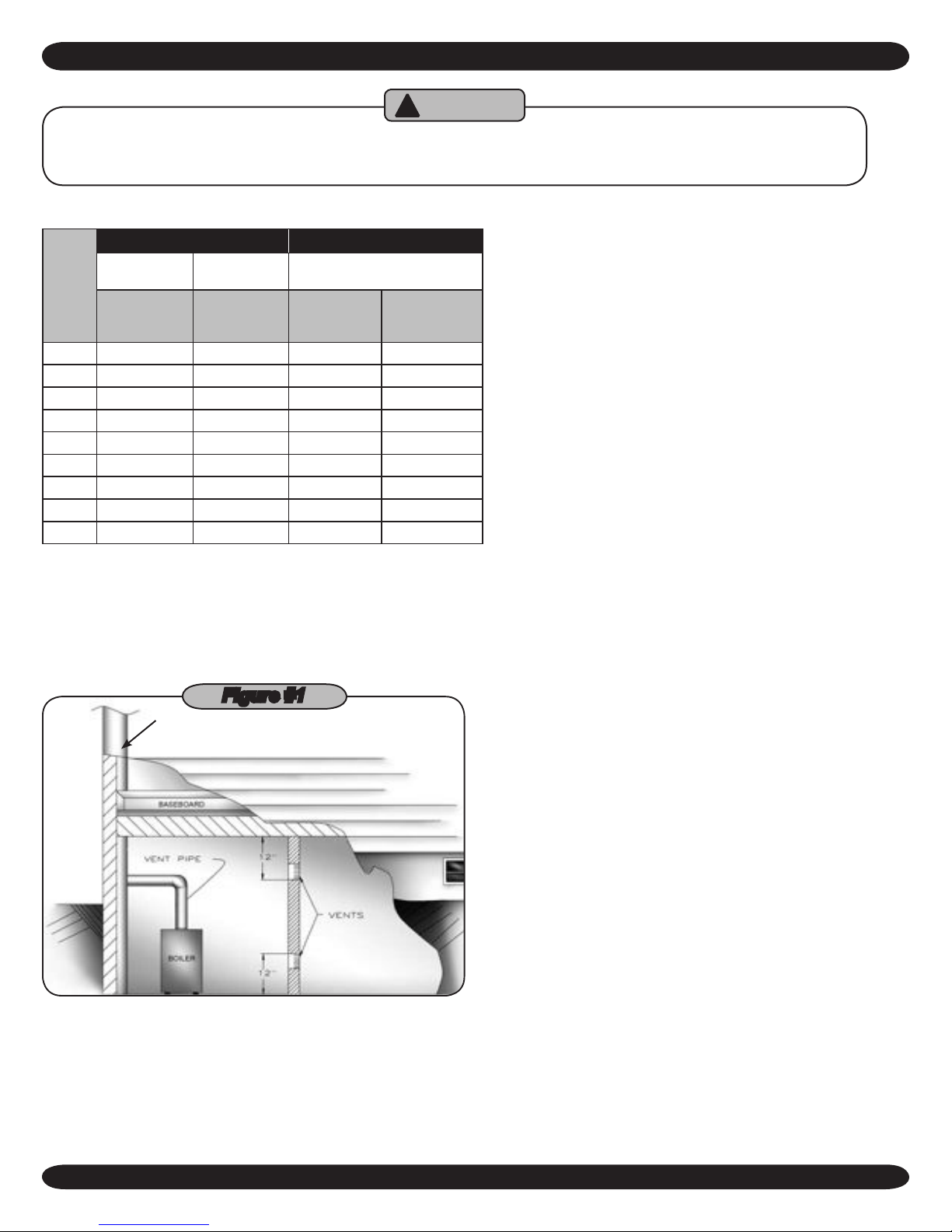
COMBUSTION AIR REQUIREMENTS
(Minimum Square Inches Requirement)
Unconfined Area* Confined Area**
Inside
Model
* A space whose volume is not less than 50 cubic feet per 1000 BTU per hour of all
appliances installed in that space (cubic feet of space = height x width x length)
** A space whose volume is less than 50 cubic feet per 1000 BTU per hour of all
appliances installed in that space (cubic feet of space = height x width x length)
1.
Combustion Air
No.
1 Sq. In./1000
Btu/Hr.
(Fig. #3)
50 100 10 13 25
75 100 15 19 38
100 100 20 25 50
125 125 25 32 63
150 150 30 38 75
175 175 35 44 88
200 200 40 50 100
250 250 50 63 125
300 300 60 75 150
Ventilation of the boiler room must be adequate to provide
Outside
Combustion Air
1 Sq. In./5000
Btu/Hr.
(Fig. #4)
Outside Combustion Air
Vertical Ducts
1 Sq. In./4000
BTU/Hr.
Horizontal Ducts
1 Sq. In./2000
BTU/Hr.
sufficient air to properly support combustion per the latest
revision of the National Fuel Gas Code, ANSI Z223.1.
Figure #1
CHIMNEY OR
TYPE B VENT PIPE
When a boiler is located in an unconfined space in a
2.
building or conventional construction frame, masonry or
metal building, infiltration normally is adequate to provide
air for combustion and ventilation. However, if the equipment is located in a building of tight construction (See the
National Fuel Gas Code, ANSI Z223.1 latest revision), the
boiler area should be considered as a confined space.
In this case air for combustion and ventilation shall be
provided according to Step 5. If there is any doubt, install
air supply provisions in accordance with the latest revision
of the National Fuel Gas Code.
When a boiler is installed in an unconfined space in a
3.
building of tight construction, air for combustion and ventilation must be obtained from outdoors or from spaces
freely communicating with the outdoors. A permanent
opening or openings having a total free area of not less
than 1 square inch per 5000 Btu per hour of total input
rating of all appliances shall be provided. Ducts may be
used to convey makeup air from the outdoors and shall
have the same cross-sectional area of the openings to
which they are connected.
4.
When air for combustion and ventilation is from inside
buildings, the confined space shall be provided with two
permanent openings, one starting 12 inches from the
top and one 12 inches from the bottom of the enclosed
space. Each opening shall have a minimum free area
of 1 square inch per 1000 Btu per hour of the total input
rating of all appliances in the enclosed space, but must
not be less than 100 square inches. These openings must
freely communicate directly with other spaces of sufficient
volume so that the combined volume of all spaces meets
the criteria for an unconfined space. (Figure #1)
5.
When the boiler is installed in a confined space and all air
is provided from the outdoors the confined space shall be
provided with one or two permanent openings according
to methods A or B. When ducts are used, they shall be
of the same cross sectional area as the free area of the
area of the openings to which they connect. The minimum
dimension of rectangular air ducts shall be not less than 3
x 3 inches or 9 square inches.
When installing two openings, one must commence with-A.
in 12 inches from the top and the other within 12 inches
from the bottom of the enclosure. The openings shall
communicate directly, or by ducts, with the outdoors or
spaces (crawl or attic) that freely communicate with the
outdoors. One of the following methods must be used to
provide adequate air for ventilation and combustion.
5
VENTILATION AND COMBUSTION AIR
National Excelsior Company
www.excelsiorhvac.com
Subject to change without notice.
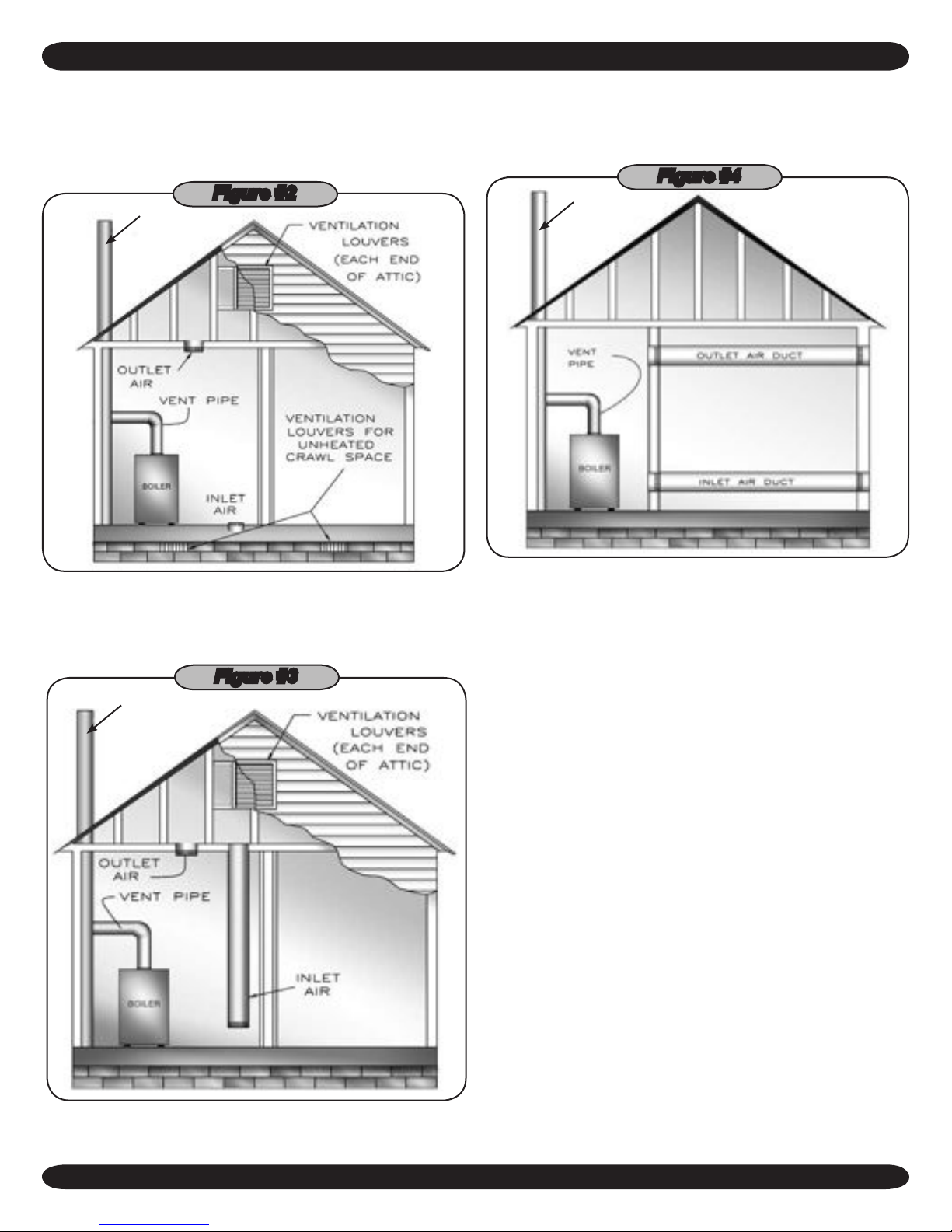
When directly communicating with the outdoors, each
1.
opening shall have a minimum free area of 1 square inch
per 4,000 Btu per hour of total input rating of all equipment in the enclosure. (Figure #2)
Figure #2
CHIMNEY OR
TYPE B VENT
PIPE
If horizontal ducts are used, each opening and duct shall
3.
have a minimum free area 1 square inch per 2,000 Btu
per hour of total input rating of all appliances in the enclosed space. (Figure #4)
Figure #4
CHIMNEY OR
TYPE B VENT
PIPE
When communicating with the outdoors by means of
2.
vertical ducts, each opening shall have a minimum free
area of 1 square inch per 4,000 Btu per hour of total input
rating of all appliances in the enclosed space. (Figure #3)
Figure #3
CHIMNEY OR
TYPE B VENT
PIPE
(DUCT ENDS 1 FT.
ABOVE THE FLOOR)
One permanent opening, commencing within 12 inches A.
of the top of the enclosure, shall be permitted where the
equipment has clearances of at least 1 inch from the
sides, 1 inch from the back, and 6 inches from the front
of the boiler. The opening shall directly communicate
with the outdoors or shall communicate through a vertical or horizontal duct to the outdoors or spaces (crawl
or attic) that freely communicate with the outdoors. The
openings must have a minimum free area of 1 square
inch per 3000 Btu per hour of the total input rating of all
equipment located in the enclosure. The free area must
be no less than the sum of the areas of all vent connectors in the confined space.
In calculating free area using louvers, grilles or screens
4.
for the above, consideration shall be given to their blocking effect. Screens used shall not be smaller than 1/4 inch
mesh. If the free area through a design of louver or grill is
known, it should be used in calculating the size opening
required to provide the free area specified. If the design
and free area is not known, it may be assumed that wood
louvers will have 20-25% free area and metal louvers and
grilles will have 60-75% free area. Louvers and grilles
should be fixed in the open position or interlocked with the
boiler so they are opened automatically during the boiler
operation.
6
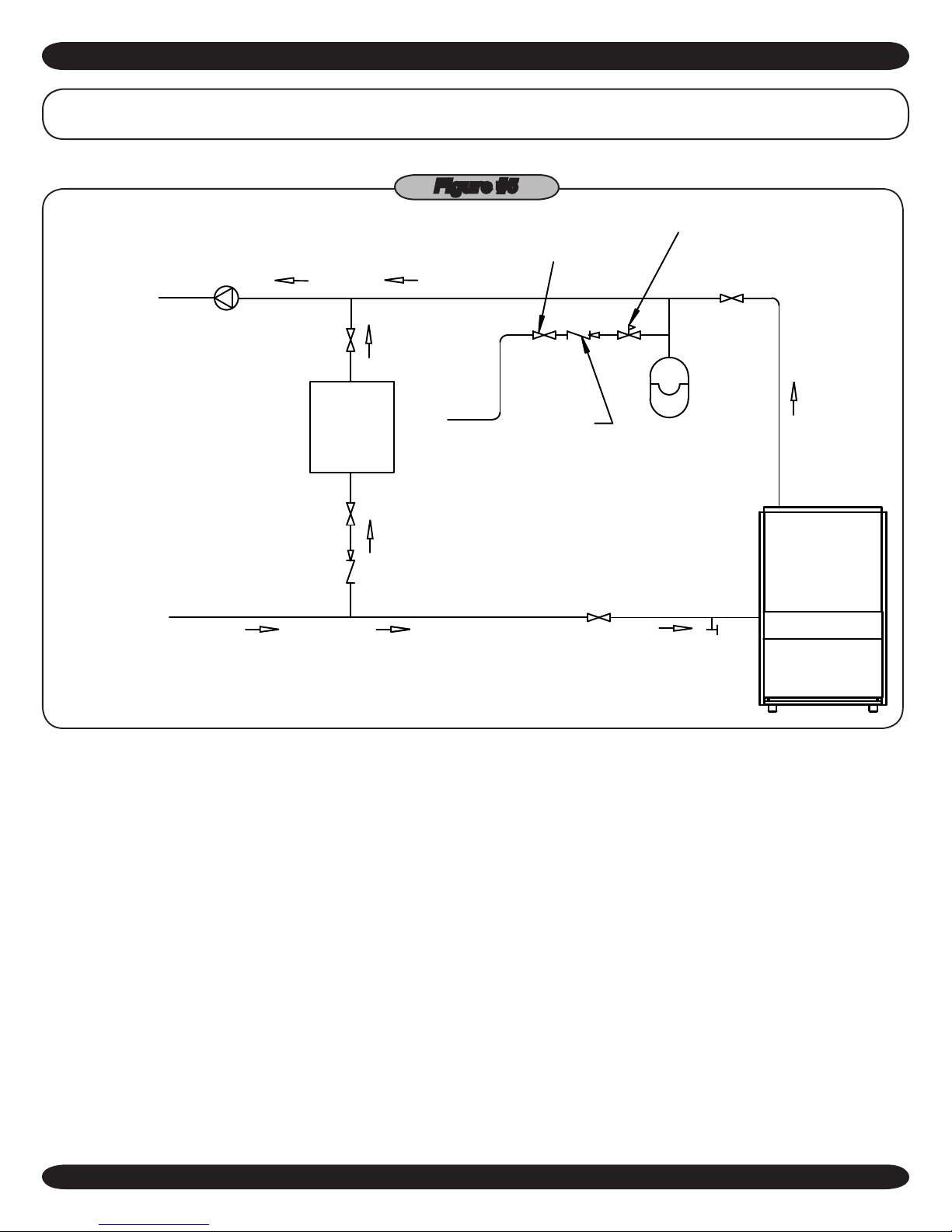
CONNECTING SUPPLY & RETURN PIPING
EXPANSION
TANK
CHECK
VALVE
B
D
FEED
WATER
C
RETURN PIPING
FROM HEATING
AND COOLING
ELEMENT
WATER
CHILLER
SUPPLY PIPING
TO HEATING
AND COOLING
ELEMENT
CIRCULATOR
A
PRESSURE
REDUCING
VALVE
PROPER
BACKFLOW
PROTECTION
DEVICE
GATE
VALVE
PURGE
VALVE
National Excelsior Company
www.excelsiorhvac.com
Subject to change without notice.
IMPORTANT: Circulators in the following illustrations are mounted on the system supply side, but
mounting on the system return side is also acceptable practice.
Figure #5
Connect supply and return piping as suggested in Figure
1.
#5 when the boiler is used in connection with refrigerated
systems.
The chilled medium MUST BE PIPED IN PARALLEL A.
with the boiler.
Use appropriate valves to prevent the chilled medium B.
from entering the heating boiler.
Maintain a minimum clearance of one inch to hot water C.
pipes.
2.
When the boiler is connected to heating coils located in air
- During heating cycle open valves A and B, close
valves C and D.
- During cooling cycle, open valves C and D, close
valves A and B.
handling units where they may be exposed to refrigerated
air circulation, the boiler piping system MUST BE supplied with flow control valves or other automatic means
to prevent gravity circulation of the boiler water during the
cooling cycle.
Hot water boilers installed above radiation level must be
3.
provided with a low water cut-off device.
When a boiler is connected to a heating system that
4.
utilizes multiple zoned circulators, each circulator must
be supplied with a flow control valve to prevent gravity
circulation.
Hot water boilers and system must be filled with water
5.
and maintained to a minimum pressure of 12 pounds per
square inch.
7

CONNECTING SUPPLY AND RETURN PIPING
BOILER
WATER INLET
ALTERNATE
CIRCULATOR
LOCATION
TO SYSTEM
FROM SYSTEM
CIRCULATOR
SHUT-OFF
VALVE
PRESSURE
REDUCER VALVE
CHECK VALVE
BALL VALVE
3 WAY MIXING
VALVE
AIR SEPARATOR
HOSE BIB
EXPANSION
TANK
BOILER
ALTERNATE
CIRCULATOR
LOCATION
TO SYSTEM
FROM SYSTEM
V2V1
CIRCULATOR
SHUT-OFF
VALVE
PRESSURE
REDUCER VALVE
CHECK VALVE
BALL VALVE
AIR SEPARATOR
ZONE VALVE
EXPANSION
TANK
WATER INLET
SYSTEM
CIRCULATOR
National Excelsior Company
www.excelsiorhvac.com
Subject to change without notice.
Figure #6
BYPASS PIPING -
AUTOMATIC MIXING VALVE
Bypass piping is an option which gives the ability to adjust
6.
the supply boiler water temperature to fit the system or
the condition of the installation. This method of piping,
however, is not typically required for baseboard heating systems. Typical installations where bypass piping is
used are as follows:
This method is used to protect boilers from condensation A.
forming due to low temperature return water. Generally
noticed in large converted gravity systems or other large
water volume systems. (Figure #6)
These methods are used to protect systems using radi-B.
ant panels and the material they are encased in from
8
BYPASS PIPING -
FIXED LOW TEMP ONLY
high temperature supply water from the boiler and protect the boiler from condensation.
NOTE#1: When using bypass piping, adjust
valves V1 & V2 until desired system temperature
is obtained.
NOTE#2: Bypass loop must be same size piping
as the supply and return piping.
7. Installation using circulators and zone valves are shown
in Figures #7-#10. For further piping information refer
to the I=B=R Installation and Piping Guide.
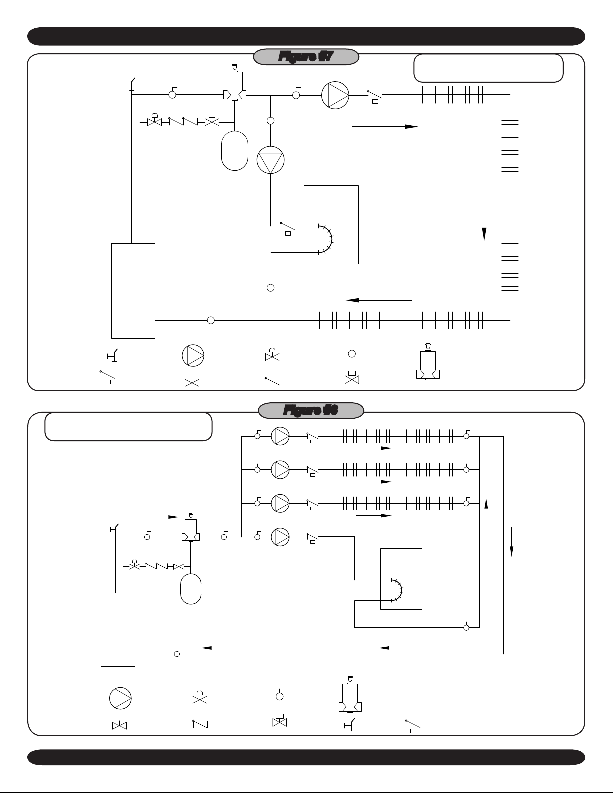
ZONE 3
ZONE 2
ZONE 1 (PRIORITY ZONE)
BOILER
ZONE 4
DHW CIRCULATOR
WATER INLET
CIRC 2
CIRC 3
CIRC 4
CIRCULATOR
SHUT-OFF
VALVE
PRESSURE
REDUCER VALVE
CHECK VALVE
BALL VALVE
AIR SEPARATOR
ZONE VALVE
HOSE BIB
FLOW CONTROL
VALVE
EXPANSION
TANK
BOILER
DHW
CIRCULATOR
CH CIRCULATOR
PRIORITY ZONE
CIRCULATOR
EXPANSION
TANK
WATER INLET
FLOW CONTROL
VAVLE
SHUT-OFF
VALVE
PRESSURE
REDUCER VALVE
CHECK VALVE
BALL VALVE
AIR SEPARATOR
ZONE VALVE
HOSE BIB
CONNECTING SUPPLY AND RETURN PIPING
National Excelsior Company
www.excelsiorhvac.com
Subject to change without notice.
Figure #7
SINGLE ZONE SYSTEM WITH
DHW PRIORITY
MULTIZONE SYSTEM WITH CIRCU-
LATORS AND DHW PRIORITY
Figure #8
9
 Loading...