

UTICA BOILERS MAH-125, MAH-165, MAC-205, MAC-150 Installation, Operation And Maintenance Manual

MAH-125
MAC-150
MAH-165
MAC-205
CONDENSING
WALL MOUNTED
GAS FIRED BOILER
Manufactured by:
ECR International Inc.
2201 Dwyer Avenue, Utica, NY 13501
Tel. 800 253 7900
www.ecrinternational.com
MAC-205

CONTENTS :
INSTALLATION, OPERATION,
AND MAINTENANCE MANUAL
(240011941)
APPLICATION GUIDE
(240011430)
COMMISSIONING
GUIDE
(240011376)
REQUIRED
INSPECTION SPECIAL
(240011561)
BACK COVER
MAH-165

CONDENSING WALL MOUNTED
INSTALLATION, OPERATION &
MAINTENANCE MANUAL
Models
MAH-125, MAC-150
MAH-165, MAC-205
GAS FIRED
Manufactured by:
2201 Dwyer Avenue, Utica, NY 13501
P/N 240011941 REV B, [0
ECR International Inc.
Tel. 800 253 7900
www.ecrinternational.com
3/31/2018]
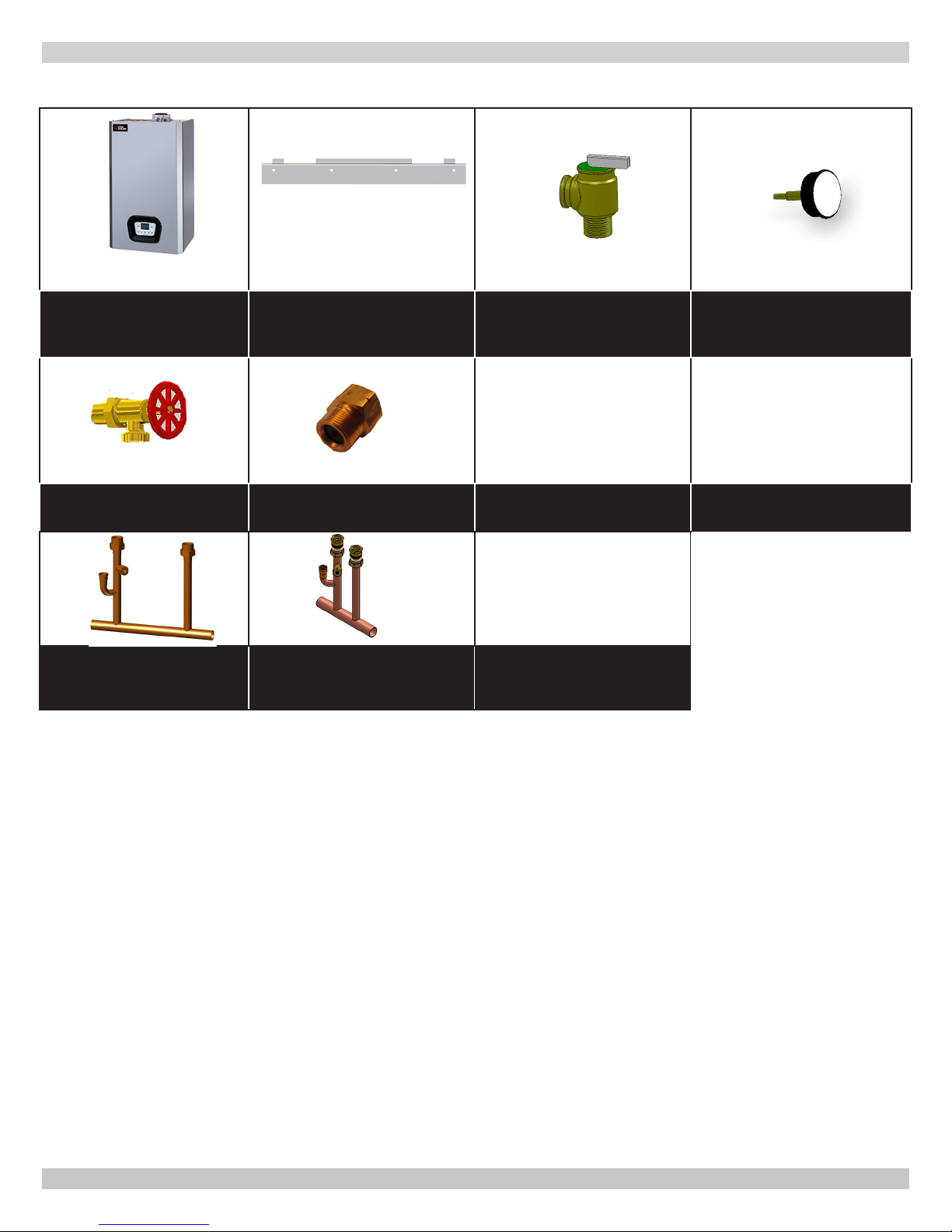
VERIFY CONTENTS RECEIVED
Fully Assembled Boiler
Drain Valve
*Manifold
* Verify proper unit size before use.
Metal Wall Bracket
w/ 4 ea Wall Screws
and Plugs
*5 GPM Flow Restrictor 205
Combi Only
*Manifold
165 Heat-Only
30 PSI Safety Relief Valve
4 ea - 17x24x2 Gaskets
Used for Valve
Connections
Wall Mount Template
Template
Temperature Pressure
Gauge
Includes Essential
Documents and Warranty
11x17 Wire Diagrams
Document Package
2
240011941 REV B, [03/31/2018]

TABLE OF CONTENTS
1 - Important Information .................................... 6
2 - Introduction .................................................... 7
3 - Component Listing .......................................... 8
4 - Locating Boiler .............................................. 12
5 - Hydronic Piping ............................................. 15
5.1 General .....................................................15
5.2 Special Conditions ....................................... 16
5.3 Safety Relief Valve and Air Vent ....................16
5.4 Trim Piping ................................................. 17
5.5 System Piping ............................................17
5.6 Low Water Cut Off .......................................18
5.7 Recommendation - Use of Strainer ................20
5.8 Central Heating System ...............................21
5.9 Domestic Hot Water Mode ............................21
5.10 Frost Protection Mode ................................21
5.11 Pump Protection .......................................21
6 - Combustion Air And Vent Piping .................... 22
6.1 General .....................................................22
6.2 Removal of Existing Boiler ............................22
6.3 Denitions .................................................23
6.4
Securing Twin Pipe Polypropylene Venting
6.5 Approved Venting Materials .........................24
6.6 Vent Termination ........................................24
6.7 Coaxial Venting Instructions .........................25
6.8 Twin Pipe Systems ...................................... 26
6.9 Flexible Vent System....................................29
6.10 Condensate Piping ..................................... 31
7 - Gas Supply Piping ......................................... 32
7.1 General .....................................................32
7.2 Leak Check Gas Piping ................................. 32
8 - Electrical Connections ................................... 33
8.1 General .....................................................33
8.2 Install Room Thermostat ..............................33
8.3 Electrical Connections .................................. 33
8.4 Access To Connection Block .......................... 34
8.5 Main Supply Connection ............................... 34
8.6 Install Room Thermostat ..............................35
8.7 Optional Electrical Connections .....................36
8.8 Indirect Storage Tank ..................................37
9 - Start Up Procedure ........................................ 38
9.1
Central Heating System Heat Only
9.2 Central Heating System Combi .....................39
9.3 System Start Up .........................................40
9.4 Fill Condensate Trap with Water ....................40
9.5 Control Panel..............................................41
9.6 Commissioning ........................................... 42
9.7 Calibration Function.....................................42
9.8 De-Aeration Function ...................................43
......... 23
............... 38
9.9 Commission Set Up (Gas) ............................43
9.10 Chimney Sweep Function (CO2 Adjust) ..... 44
9.11 Combustion Adjustment Function ................44
9.12 Check Firing Rate.......................................44
9.13 Parameter Settings ....................................45
9.14 Description Of Parameters: Factory Settings...........45
9.15 Adjusting Maximum Heating Power...............47
10 - Operating instructions ................................ 48
10.1 Boiler Sequence Of Operation .....................48
10.2 Testing For Gas Leaks And Purging ........... 48
10.3 Boiler Controls .......................................... 49
10.4 Boiler Operation ........................................ 50
10.5 Central Heating Mode ................................50
10.6 Domestic Hot Water Mode ..........................50
10.7 Frost Protection ........................................50
10.8 Pump ......................................................50
10.9 Low Water Pressure Sensor ........................50
11 - General Maintenance and Cleaning.............. 51
11.1 Beginning of Each Heating Season ............ 51
11.2 Maintenance And Routine Servicing .......... 52
11.3
Component Replacement And Cleaning .........
11.4 Draining the Boiler ....................................53
11.5 Draining the Heating Circuit ........................ 53
11.6 Hydraulic Unit (DHW) ................................54
11.7 Cleaning The Cold Water Filter ....................54
11.8 Final Commissioning .................................. 54
11.9 Final Assembly..........................................54
11.10 User Information ..................................... 55
11.11 Safety Flue Thermostat
11.12 Flue Pressure Switch
11.13 Replacement Parts ...................................55
11.14 Automatic Calibration Function ............... 55
12 - Ratings And Capacities ................................ 56
12.1 Ratings and Capacity .................................56
12.2 Domestic Hot Water Specications...............56
12.3 High Altitude Parameter .............................57
13 - Trouble Shooting ......................................... 58
13.1
Error Messages And Resetting The Boiler
14 - Glossary ..................................................... 59
Appendix A - Wiring Diagrams ........................... 61
3
.................................
.....................................
....... 58
240011941 REV B, [03/31/2018]
52
55
55

Dimensions
PHYSICAL DATA
SYSTEM
DIMENSIONS
A
Height 30" [763 mm] 30 " [763 mm]
B
Width 17 " [450 mm] 17 " [450 mm]
C
Depth 13 " [345 mm] 21 [571 mm]
D
Condensate Trap Connection
E
System Supply
F
DHW Outlet (125 Optional)
Gas Connection
G
DHW (Cold Water) Inlet
H
System Return
I
Boiler Filling Connection 1/2" [15.9mm] External to Boiler
J
Primary Water Content 1 gal [3.60 L] 1 gal [4.73 L]
Central Heating (Sealed System) 125 / 150
Heat Exchanger Max Allowable Working
Pressure
125 & 150 205 & 165
13/16"
[21mm] ID
3/4” [19.1 mm] 1” [25.4mm]
1/2” [15.9 mm] 3/4” [19.1 mm]
3/4” [19.1 mm] 3/4” [19.1 mm]
1/2” [15.9 mm] 3/4” [19.1 mm]
3/4” [19.1 mm] 1” [25.4mm]
50 psi [3.45 bar] 50 psi [3.45 bar]
Hose
3/4"
[19.1 mm]
NPT
165/ 205
Max System Pressure
Min System Pressure
Max System temperature
Pressure Relief Valve Setting
Expansion Tank Minimum Size
(pre-charge press.)
Recommended System Pressure (cold)
Domestic Hot Water (Sealed System)
Max Inlet Water Pressure 116 psi [8 bar] 116 psi [8 bar]
Min Inlet Water Pressure 2.9 psi [ 0.2 bar] 2.9 psi [0.2 bar]
Min DHW Flow Rate 0.55 gpm [2.50 L/min] 0.55 gpm [2.50 L/min]
Max DHW Temperature 140°F [60°C] 140°F [60° C]
DHW Water Content 0.05 gal [0.23 L] 0.10 gal [0.37 L]
43.00 psi [2.96 bar] 43.00 psi [2.96 bar]
7.25 psi [ 0.50 bar] 7.25 psi [0.50 bar]
176°F [80°C] 176°F [80°C]
30.00 psi [2.11 bar] 30.00 psi [2.11 bar]
2.2 gal at 11.6 psi
[10.0 L at 0.8 bar]
2.2 gal at 11.6 psi
[10.0 L at 0.8 bar]
21.7 psi [1.5 bar] 21.7 psi [1.5 bar]
150 205
When boiler is operating at maximum operating temperature, providing heating with all heat emitters operating, pressure gauge
should not indicate more than 26.11 psi / 1.80 bar. If reading exceeds this gure larger expansion tank is required.
4
240011941 REV B, [03/31/2018]

PHYSICAL DATA
Front View
All Models
B
A
C
125 HEAT
ONLY
Bottom View
Dimensions
E
D
F J
165 HEAT
ONLY
Bottom View
Dimensions
IG
D
E IG
C
Top View
All Models
B
Combustion
Air
Connector
Vent
B
150 COMBI
Bottom View
Dimensions
E
D
F J
IG
205 COMBI
Bottom View
Dimensions
DCE IHGF
C
B
B
5
240011941 REV B, [03/31/2018]
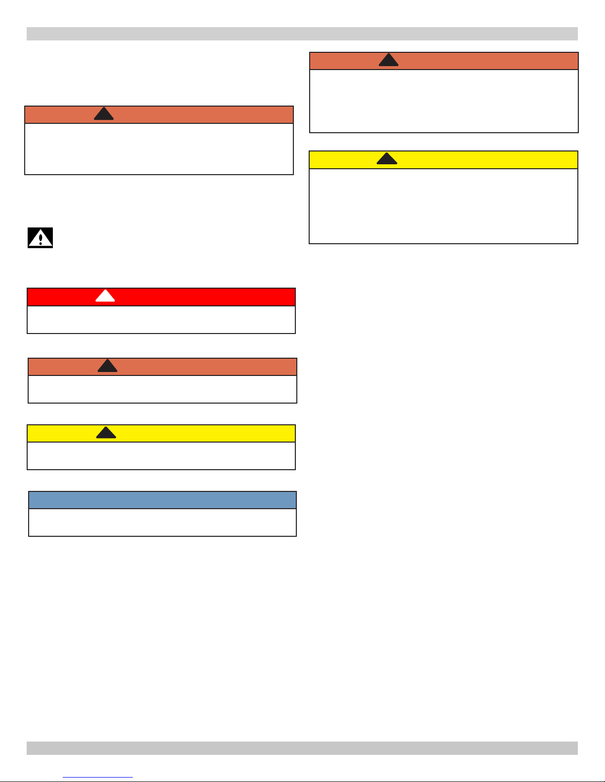
1 - IMPORTANT INFORMATION
1. Safety Information
Boiler installation shall be completed by qualied agency. See
glossary for additional information.
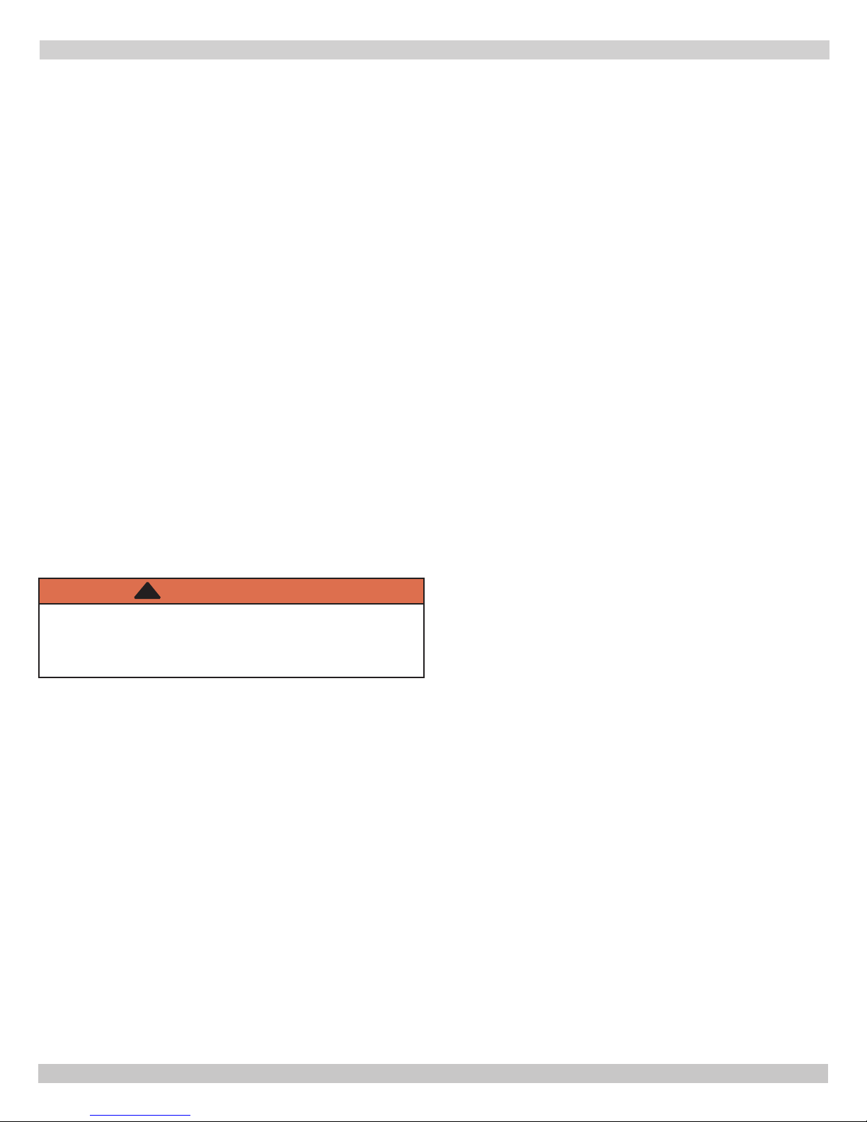
!
WARNING
Fire, explosion, asphyxiation and electrical shock
hazard. Improper installation could result in death or
serious injury. Read this manual and understand all
requirements before beginning installation.
Become familiar with symbols identifying potential hazards.
This is the safety alert symbol. Symbol alerts you
to potential personal injury hazards. Obey all safety
messages following this symbol to avoid possible
injury or death.
!
DANGER
Indicates a hazardous situation which, if not avoided,
WILL result in death or serious injury.
!
WARNING
Do not tamper with or use this boiler for any purpose
other than its intended use. Failure to follow these
instructions could result in death or serious injury.
Use only manufacturer recommended parts and
accessories.
!
CAUTION
Laceration, burn hazard. Metal edges and parts may
have sharp edges and/or may be hot. Use appropriate
personal protection equipment to include safety
glasses and gloves when installing or servicing this
boiler. Failure to follow these instructions could result
in minor or moderate injury.
!
WARNING
Indicates a hazardous situation which, if not avoided,
could result in death or serious injury.
!
CAUTION
Indicates a hazardous situation which, if not avoided,
could result in minor or moderate injury.
NOTICE
Used to address practices not related to personal
injury.
6
240011941 REV B, [03/31/2018]

2 - INTRODUCTION
2 - Introduction
2.1 Installation shall conform to requirements of authority
having jurisdiction or in absence of such requirements:
UNITED STATES
• National Fuel Gas Code, ANSI Z223.1/NFPA 54
• National Electrical Code, NFPA 70.
CANADA
• Natural Gas and Propane Installation Code, CAN/CSA
B149.1.
• Canadian Electrical Code, Part I, Safety Standard for
Electrical Installations, CSA C22.1
2.2 Where required by authority having jurisdiction,
installation shall conform to Standard for Controls and Safety
Devices for Automatically Fired Boilers, ANSI/ASME CSD-1.
Additional manual reset low water cutoff may be required.
2.3 Requirements for Commonwealth of
Massachusetts:
Boiler installation must conform to Commonwealth of
Massachusetts code 248 CMR which includes but is not limited
to:
Installation by licensed plumber or gas tter.
.
2.5 Designated Use
• MAC-150 and MAC -205 provide both central heating
and domestic hot water.
• MAH-125 and MAH-165 central heating only.
• Indoor installation.
• Closet or alcove installation. Direct Vent Boiler does not
require air vents when installed in closet or room.
• Direct vent boiler.
• For use with natural gas or liqueed petroleum gases
(LP/propane).
2.6 The unit MUST NOT:
• Directly heat potable water. Indirect heating is
acceptable.
• Heat water with non-hydronic heating system chemicals
present (example, swimming pool water).
• Toxic chemicals, such as those used for boiler
treatment, shall not be introduced into potable water
used for space heating.
• Exceed 43 psig (2.96bar) maximum allowable working
pressure, or drop below minimum system pressure 7.25
psig (.50 bar)
• Exceed 176°F (80°C) system design temperature.
2.4 Manufacturer recommends use of Carbon
Monoxide monitor may be requirement of local
jurisdiction.
2.7 Operational Features
• Modulates to provide CH Turndown 5.5:1, DHW
Turndown 7:1.
• Maximum output available for domestic hot water:
MAC-150 - 136,000 btu/h (40 kW), capable of providing
3.5 (U.S.) gpm (13.2 liters/min) with a temperature rise
of 70°F/39°C.
MAC-205 - 180,000 btu/h (53 kW), capable of providing
5.0 (U.S.) gpm (18.9 litres/min) with temperature rise of
70°F/39°C.
• Integral Low Water Pressure Cutoff.
• Optional Outdoor Temperature Reset.
• Heat exchanger over heat protection.
• Boiler operating at maximum operating temperature,
providing heat, pressure gauge should not indicate
more than 26.11 psi / 1.80 bar. If reading exceeds this
gure larger expansion tank is required.
Check our website frequently for updates: www.ecrinternational.com
Information and specications outlined in this manual in effect at the
time of printing of this manual. ECR International reserves the right to
discontinue, change specications or system design at any time without
notice and without incurring any obligation, whatsoever.
7
240011941 REV B, [03/31/2018]

11
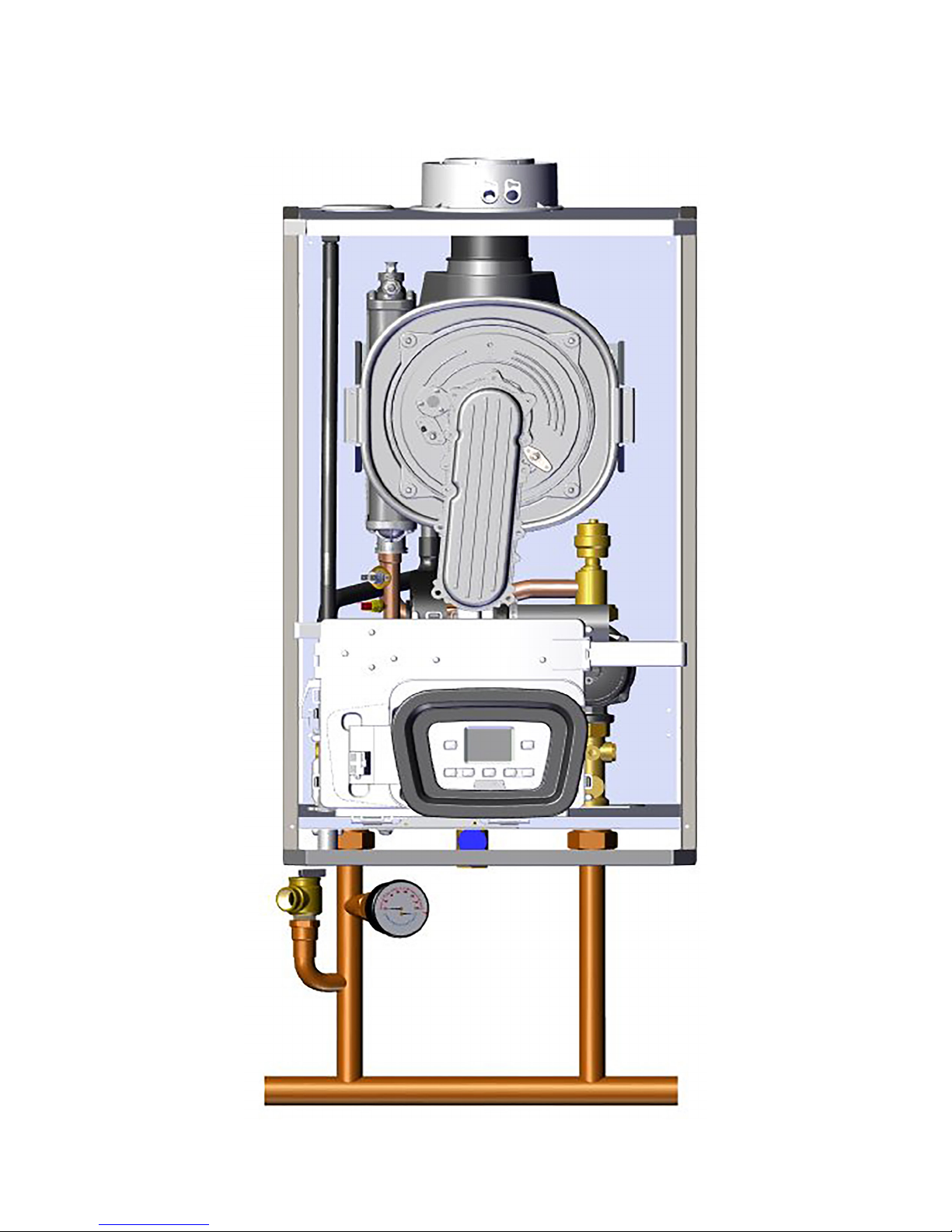
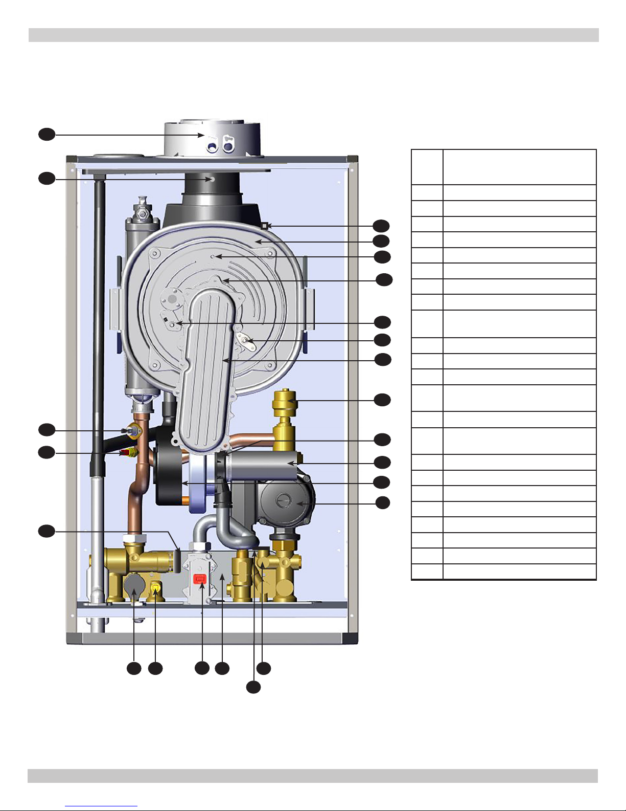
3 - COMPONENT LISTING
UTICA BOILER MAH-125
10
9
8
7
12
13
14
15
16
17
18
19
25
ITEM
NO.
1 Pump with Air Separator
2 Boiler Drain Tap
3 Boiler Filling Tap
4 Gas Valve
5 Low Water Pressure Cutoff
6 3-Way Valve with Motor
7
Water Safety Thermostat
NTC Heating sensor (Flow/Return)
8
QTY 2, (1 Shown for clarity)
9 Flue Sensor
Pressure Switch
10
11 Coaxial Flue Connector
Heat Exchanger Temperature
12
Sensor
13 Heat Exchanger
14 Burner (not shown)
15 Ignition electrode
16 Flame Detection Electrode
17 Air/Gas Manifold
18 Venturi
19 Fan
Utica Boiler
MAH-125
6
5
4
3
Illustrations are a depiction of the boiler for general location of parts and may vary depending on model.
1
2
8
240011941 REV B, [03/31/2018]

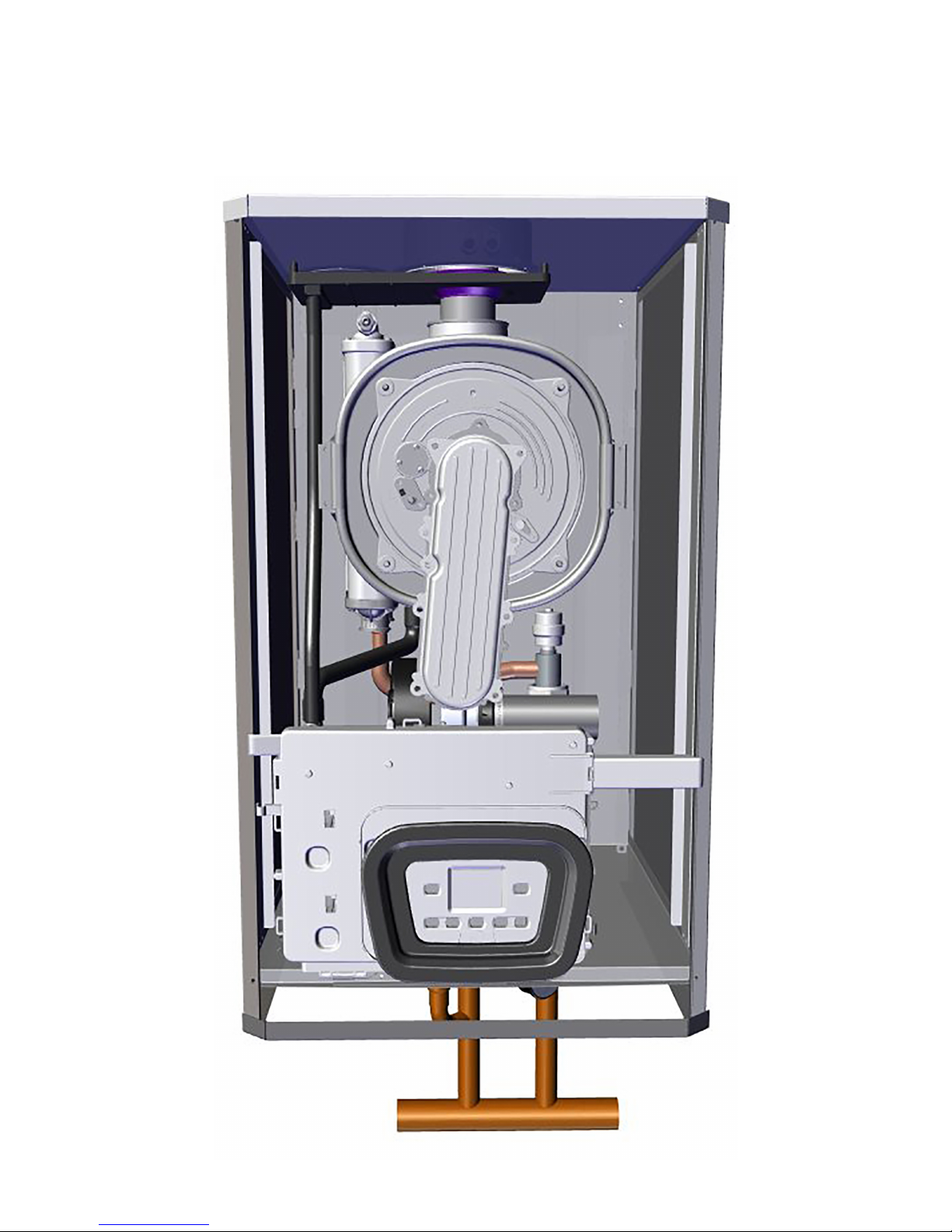
3 - COMPONENT LISTING
UTICA BOILER MAH-165
8
ITEM
NO.
1 Pump
7
9
10
11
12
13
14
15
6
5
16
17
18
19
1
2 Boiler Drain Tap
3 Low Water Pressure Cutoff
Gas Valve
4
NTC Heating sensor (Flow/Return)
5
QTY 2, (1 Shown for clarity)
6 Water Safety Thermostat
7 Flue Sensor
8 Coaxial Connector
Heat Exchanger Termperature
9
Sensor
10 Heat Exchanger
Burner Door Termperature
11
Sensor
12 Burner (not shown)
13 Ignition Electrode
14 Flame Detection Electrode
15 Air/Gas Blend Manifold
16 Air Purge
17 Venturi
18 Silencer
19 Fan
Utica Boiler
MAH-165
4
Illustrations are a depiction of the boiler for general location of parts and may vary depending on model.
2
3
9
240011941 REV B, [03/31/2018]

16
3 - COMPONENT LISTING
UTICA BOILER MAC-150
14
13
12
11
10
17
18
19
20
21
22
23
24
2
ITEM
NO.
1 Pump with Air Separator
2 Boiler Drain Tap
Flow Sensor with Water Filter
3
and Flow Restrictor
4 DHW Priority Sensor
5 Boiler Filling Tap
6 Gas Valve
7 NTC DHW Sensor
8 Low Water Pressure Cutoff
9 3-Way Valve with Motor
10 Check Valve
11 DHW Heat Exchanger
12 Water Safety Thermostat
NTC Heating sensor (Flow/Return)
13
QTY 2, (1 Shown for clarity)
14 Flue Sensor
Pressure Switch
15
Coaxial Connector
16
Heat Exchanger Temperature
17
Sensor
18 Heat Exchanger
19 Burner (not shown)
1
20 Ignition Electrode
21 Flame Detection Electrode
22 Air/Gas Blend Manifold
23 Venturi
24 Fan
Utica Boiler
MAC- 150
9
8157
6
3
5
4
Illustrations are a depiction of the boiler for general location of parts and may vary depending on model.
10
240011941 REV B, [03/31/2018]
12
3 - COMPONENT LISTING
UTICA BOILER MAC-205
11
10
9
8
13
14
15
16
17
18
19
20
21
22
23
1
ITEM
NO.
1 Pump
2 Flow Sensor
3 DHW Priority Sensor
4 DHW Heat Exchanger
5 Gas Valve
6 NTC DHW Sensor
7 Low Water Pressure Cutoff
8 3-Way Valve with Motor
NTC Heating sensor (Flow/Return)
9
QTY 2, (1 Shown for clarity)
10 Water Safety Thermostat
11 Flue Sensor
12 Coaxial Connector
Heat Exchanger Temperature
13
Sensor
Heat Exchanger
14
Burner Door Temperature
15
Sensor
16 Burner (not shown)
17 Ignition Electrode
18 Flame Detection Electrode
19 Air/Gas Manifold
20 Air Purge
21 Venturi
22 Silencer
23 Fan
Utica Boiler
MAC-205
5
7
4
26
3
Illustrations are a depiction of the boiler for general location of parts and may vary depending on model.
11
240011941 REV B, [03/31/2018]
4 - LOCATING BOILER
!
WARNING
Fire Hazard! Do not install on carpeting. Failure to
follow these instructions could result in death or
serious injury.
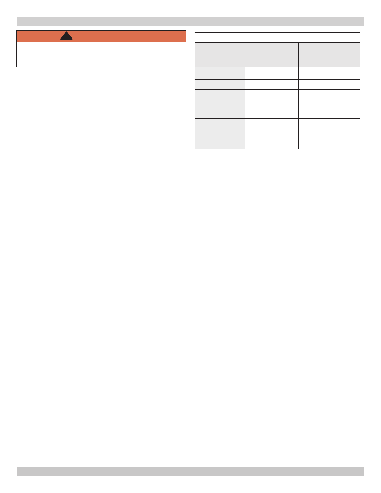
TABLE 1: BOILER CLEARANCES
Dimension
Combustible
Materials
(1)
Manufacturer
Recommended
for Service
(1)(2)
4.1 Boiler Location Considerations
• Ambient room temperature always above 32°F (0°C) to
prevent freezing of liquid condensate.
• Approved for installation in closets or alcove provided
it is correctly designed for that purpose and minimum
clearances are met.
• Protect gas ignition system components from water
(dripping, spraying, rain, etc.) during operation and
service (circulator replacement, condensate trap,
control replacement, etc.).
• Access to outdoors to meet minimum and maximum
pipe lengths for combustion air and vent piping. See
section 6.
• Disposal of condensate. See section 6.
• Drainage of water (or water - antifreeze solution)
during boiler service or from safety relief valve
discharge. See section 5.
• Access to system water piping, gas supply, and
electrical service. See sections 5, 7 and 8.
• Clearances to combustible materials and service
clearances. See Table 1 and Figures pg. 11.
• Boiler shall be installed on at vertical wall which is
capable of supporting the weight of the boiler.
• Room-sealed boiler installed in a room containing bath
or shower shall be installed so person using bath or
shower cannot touch any electrical switch or boiler
control utilizing line voltage electricity.
• Multiple Boilers can be wall mounted, placed side by
side, or back to back.
• Observe service clearances in all installations.
• For Direct Vent installations, air vents are not required
in room boiler is installed in, or when installed in closet
or compartment.
Top
Left Side
Right Side
Front
Back
Bottom
Combustion Air/
Vent piping
(1)
Required distances measured from boiler jacket.
(2)
Service, proper operation clearance recommendation.
* Allowance for piping at the bottom of boiler not included.
0" (0 cm) 8-5/8" (220 mm)
1-3/4" (45 mm) 1-3/4" (45 mm)
1-3/4" (45 mm) 1-3/4" (45 mm)
0" (0 cm)
0" (0 cm)
0" (0 cm)
0" (0 cm) 6" (160 mm)
17-3/4"(450mm)
0" (0 cm)
*9-13/16"
(250 mm)
NOTE: Greater clearances for access should supersede re
protection clearances.
12
240011941 REV B, [03/31/2018]

4 - LOCATING BOILER
4.2 Service and Combustible Clearances
Left Side View
of Boiler
CLEARANCES REQUIRED FOR
125 & 150
13 in
[345 mm]
165 & 205
21½in
[571.5 mm]
13.58 in /
345.00 mm
30 in
[763 mm]
CLOSET INSTALLATION
1 in
[45mm]
Minimum Clearance
17 ¾ in. [450mm ]
From Front of Boiler
Front View of
Boiler
8 ⅝in [220 mm]
17 in
[450mm]
1 in
[45mm]
9 in [250 mm]
CLEARANCES FOR
COMBUSTIBLES
Back
Top View
1 in
[45mm]
1 in
[40mm]
1 in
[45mm]
Closet Installation
0 in /0 mm between Back of Unit and wall
1in
[45 mm]
17in
[450 mm]
Front View of
Boiler
1in
[45 mm]
13
240011941 REV B, [03/31/2018]
4 - LOCATING BOILER
!
CAUTION
Boiler weight exceeds 140 pounds (63.5 kg). Do not
lift boiler onto wall without assistance.
Note
Note
4.2 Wall Mounting
1.
Decide position of boiler on the wall allowing for all
required clearances and ue terminal position.
2.
Tape template to the wall. Ensure template is level and
upright. Mark position of holes for boiler mounting bracket
and plumbing connections.
3.
Rear exit ue - mark position of hole for ue.
4.
Side exit ue - mark horizontal center line of ue across
the wall to side wall, then along side wall (ensure lines are
parallel and sloped properly towards the boiler, refer to
section 6. This will give position of center of hole for ue.
5.
Cut hole in wall for coaxial ue. See sizing below:
Lift boiler using chassis. Do not use front jacket,
vent piping, water or gas ttings to lift boiler as it
may cause damage to the boiler.
Use two (2) wrenches when tightening and tting
to pipe boiler's threaded ttings. Boiler's internal
piping can be damaged if subjected to excessive
torque.
• 125 & 150 - 4 " [110 mm] diameter
• 165 & 205 - 5 " [135 mm] diameter
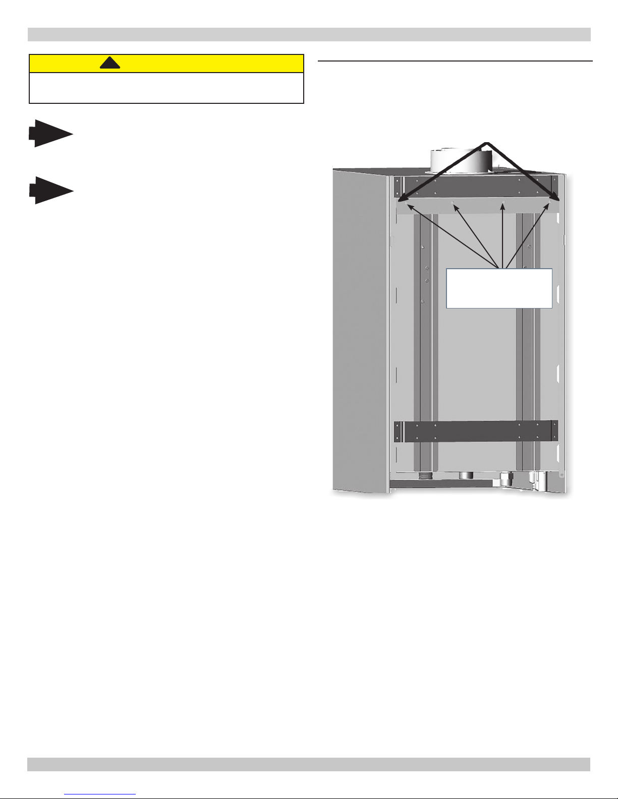
FIGURE 4-2 Wall Mount Bracket (Included)
Center brackets. Avoid
overhang on sides of
wall mount bracket.
Use four (4) predrilled
holes for mounting
bracket to wall
6.
Pre-pipe supply and return water connections with factory
ttings before wall mounting.
7.
Mount boiler on wall using wall mounting bracket included
with unit.
8.
Adjust the position of the boiler verify it is level.
14
240011941 REV B, [03/31/2018]

5 - HYDRONIC PIPING
Note
Note
Note
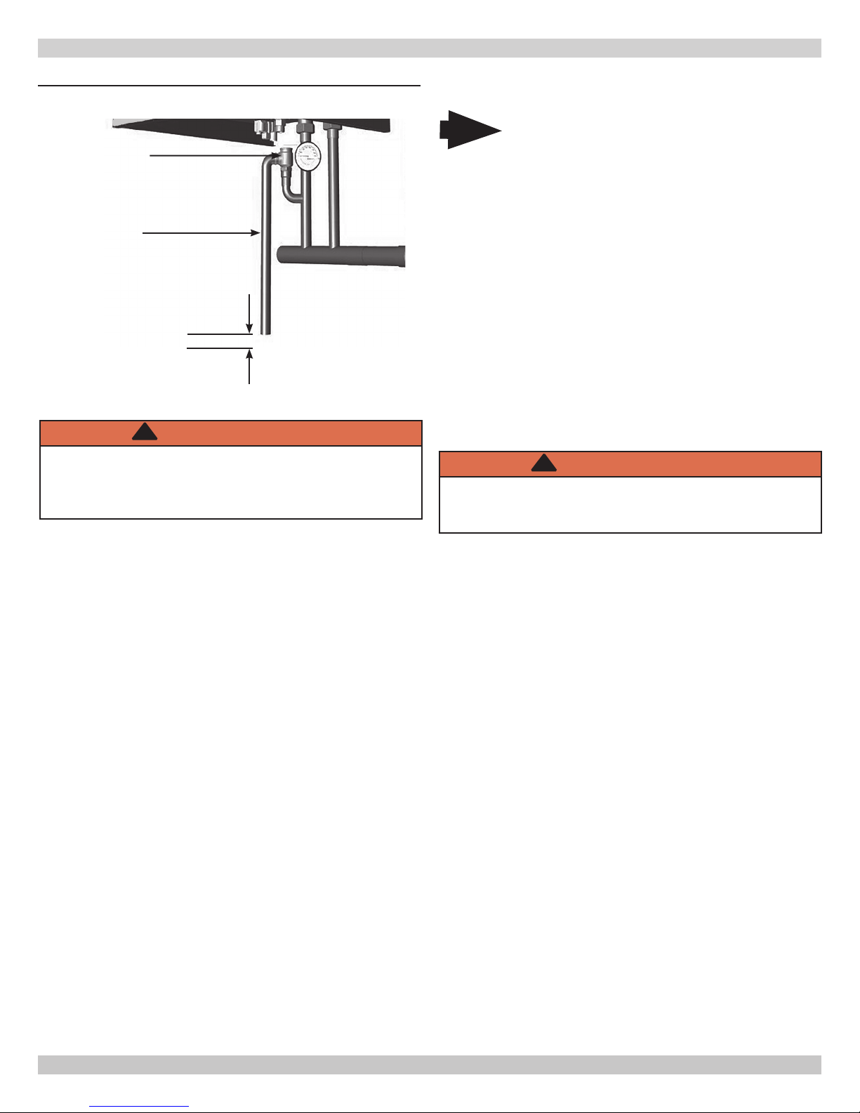
FIGURE 5-1 Safety Relief Valve
System Supply
Safety Relief
Boiler rated at 50 psig (345 kPa) maximum
allowable working pressure. Boiler provided with
30 psig (206 kPa) safety relief valve.
When installing safety relief valve it must be
installed in a vertical position with spindle at
top.
System pressure above 43 psi [2.96 bar] WILL
result in boiler shutting down.
Valve
System Return
!
WARNING
Boiler and its individual shutoff valve shall be
disconnected from gas supply piping system during
any pressure testing of that system at test pressures
in excess of 1/2 psi (3.40 kPa - 34.47 mbar).
Boiler shall be isolated from the gas supply piping
system by closing its individual manual shutoff valve
during any pressure testing of gas supply piping
system at test pressures equal to or less than 1/2 psi
(3.5 kPa).
Install boiler so that gas ignition system components
are protected from water (dripping, spraying,rain,
etc.) during appliance operation and service (circulator
replacement, condensate trap, control replacement,
etc.).
5.1 General
• Primary/Secondary piping required.
• Install piping in accordance with authority having
jurisdiction.
• Support system piping and safety relief valve discharge
piping. Boiler's internal piping and wall mount bracket
can be damaged if subjected to excessive weight.
TP Gauge
WARNING
!
• Poison hazard. Ethylene glycol is toxic. Do not use
ethylene glycol.
• Never use automotive or standard glycol antifreeze,
even ethylene glycol made for hydronic systems.
• Ethylene glycol can attack gaskets and seals used in
hydronic systems.
• Do not use petroleum based cleaning or sealing
compounds boiler system.
• Do not ll boiler or boiler system with softened
water.
• Use only inhibited propylene glycol solutions
certied by uid manufacturer as acceptable for use
with closed water heating system.
• Thoroughly clean and ush any system that used
glycol before installing new Boiler.
• Provide user with Material Safety Data Sheet
(MSDS) on uid used.
NOTICE
The intended use of the internal heat exchanger pump
is a boiler loop. Do not use as a primary system pump.
• Size central heating pump (and domestic hot water
pump, if used) for system requirements only. Internal
heat exchanger pump compensates for pressure drop
through boiler internal piping and heat exchanger.
• Thoroughly clean and ush system before connecting
to boiler.
• If oil is present in system water, use approved
detergent to wash system.
• It is necessary to semi-annually check the water
quality of central heating systems.
• Flush system to remove any solid objects such as metal
chips, bers, or Teon tape, etc.
• Flush system until water runs clean and piping is free
of sediment.
• Use purge valve to ush zoned systems, each zone
separately. If purge valves and isolation valves are not
installed, install them to properly clean the system.
• When purging installations that include standing iron
radiators and systems with manual vents at high
points, start with nearest manual air vent. Open the
vent until water ows out, then close vent. Repeat this
procedure, working toward furthest air vent.
• Install a basket strainer if large amounts of sediment is
present. Keep basket clear of sediment build up.
• Manufacturer recommends a water treatment product
be used for sediment removal.
• Ensure piping in the heating system has an oxygen
barrier.
15
240011941 REV B, [03/31/2018]
5 - HYDRONIC PIPING
FIGURE 5-2 Safety Relief Valve Discharge Piping
Safety Relief Valve
Do not use
plastic pipe see
Warning below.
Check Local Codes For
Maximum Distance To Floor
!
WARNING
Burn and scald hazard. Safety relief valve could
discharge steam or hot water during operation.
Use pipe suitable for temperatures of 375°F (191°C) or
greater. DO NOT use plastic pipe.
5.2 Special Conditions
Do not expose boiler and condensate piping to
Note
freezing temperatures.
• System piping exposed to freezing conditions: Use
inhibited propylene glycol solutions certied by uid
manufacturer for use with closed water heating system.
Do not use automotive or ethylene glycol.
• Boiler installed above radiation level (or as required
by authority having jurisdiction). Integral low water
pressure switch is provided in boiler.
• Boiler used in connection with refrigeration system.
Install piping in parallel with boiler, with appropriate
valves to prevent chilled medium from entering boiler.
• System piping connected to heating coils located in air
handling unit exposed to refrigerated air circulation.
Install ow control valves or other automatic means
to prevent gravity circulation of boiler water during
cooling cycle.
!
WARNING
Burn and scald hazard. Safety relief valve could
discharge steam or hot water during operation.
Install discharge piping per these instructions.
5.3 Safety Relief Valve and Air Vent
• Install safety relief valve using pipe tting provided
with boiler. See Figure 5-2.
• Install safety relief valve with spindle in vertical
position.
• Do not install shutoff valve between boiler and safety
relief valve.
• Install discharge piping from safety relief valve. Do not
use plastic pipe.
• Use ¾" or larger pipe.
• Use pipe suitable for temperatures of 375°F (191°C) or
greater. Do not use plastic pipe on safety relief valve.
• Individual boiler discharge piping shall be independent
of other discharge piping.
• Size and arrange discharge piping to avoid reducing
safety relief valve relieving capacity below minimum
relief valve capacity stated on rating plate.
• Run pipe as short and straight as possible to location
protecting user from scalding and properly drain piping.
• Install union, if used, close to safety relief valve outlet.
• Install elbow(s), if used, close to safety relief valve
outlet and downstream of union (if used).
• Terminate pipe with plain end (not threaded).
16
240011941 REV B, [03/31/2018]
5 - HYDRONIC PIPING
5.4 Trim Piping
• Temperature - Pressure Gauge. Install temperature
pressure gauge using piping provided with boiler. See
Figure 5-1.
• Some boiler models may have integral drain valve located
inside jacket directly underneath pump. Install provided
external drain valve as required.
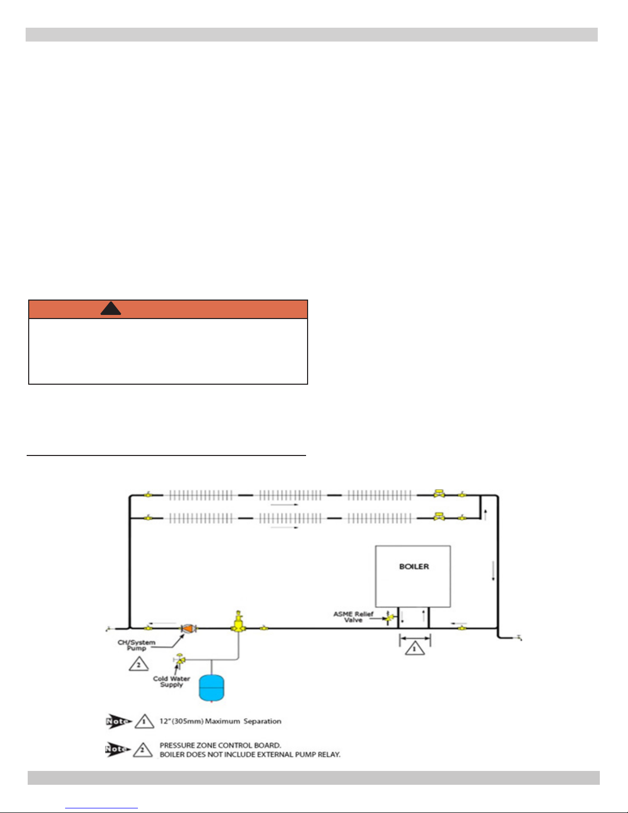
5.5 System Piping
• Ensure caps are removed from boiler water connections.
• See Figure 5-9 for basic system piping congurations.
• Systems with automatic ll valves require back ow
prevention device.
• Single boiler system. See Figures 5-4, 5-5,
guidance. Additional considerations:
• Boiler control is designed for single central heating
pump. Installer responsible for integration of
multiple central heating pumps.
• Boiler control allows domestic hot water
pri orit ization. Function could be lost if central heating
pump is not directly connected to control system.
• Multiple boiler system. Considerations:
• Control system requires equivalent water
temperatures entering each boiler to properly sequence
and adjust system supply temperature.
for general
• Ensure washers supplied are utilized.
• Face valves and ttings to rear wall.
• Fit union bends to valves.
A. If soldering to boiler union bends, ensure bends are
not connected to the valves, otherwise internal seals
may be damaged.
B. Verify 3/4" [22.2 mm] isolating valve with lter is
tted to heating return connection.
C. Fit pressure relief valve connection vertically before
heating isolating valve.
• Connect system valve pipe work to the boiler.
• Route pressure relief valve discharge piping to the oor.
Follow local code with respect to necessary distance to the
oor. See Figure 5-2.
• Verify all valves are closed.
!
WARNING
Burn and scald hazard. Verify all plastic caps are
removed from boiler connections. Failure to follow
these instructions could result in death or serious
injury.
• Thoroughly ush all hydronic piping.
• Secure all valves/ttings to boiler.
17
240011941 REV B, [03/31/2018]

5 - HYDRONIC PIPING
FIGURE 5-3 - Piping Diagram - LWCO Location
Low Water Cutoff (LWCO)
(See Figure 5-5 for detail)
Supply
Position LWCO Above
Top of Boiler
Air Vent
Gas
Boiler
Note
Note
Arrange piping to prevent
water dripping onto boiler.
Illustrations are meant to
show system piping concept
only. Installer is responsible
for all equipment and detailing
required by authority having
jurisdiction.
Return
1
Safety Relief
Valve
* Check Local Codes for
Maximum Distance to
Floor.
5 gpm Limiter
Factory Installed
205 Only
*To Drain
Note
DO NOT PLACE ISOLATION VALVE
1
BEFORE TEE OR LWCO.
18
1
240011941 REV B, [03/31/2018]

5 - HYDRONIC PIPING
5.6 External Optional Low Water Cut Off
These guidelines are supplied when necessary to install an
additional Low Water Cut Off (LWCO), for sensing a low water
level condition in a boiler, as required by the Authority Having
Jurisdiction.
Follow LWCO manufacturer installation instructions for type of
LWCO selected in addition to these instructions.
LWCO shall be 120V/60HZ control and dry contacts sized for
load being connected. Wire control to boiler. See Figure 5-4.
Connect LWCO device to the system ground. Ground in
accordance with the requirements of the authority having
jurisdiction or, in the absence of such requirements, with the
National Electrical Code (NEC) or Canadian Electrical Code
CEC.
• Locate LWCO sensing device in the supply
piping, above the minimum height of boiler.
See Figure 5-3, Piping Diagram.
• Position control in HORIZONTAL piping to assure proper
boiler protection (upright or 90° rotation).
• For proper operation, sensing element of the LWCO
control shall be positioned in the tee to sense the main
water stream. Maintain minimum 1/4” spacing from pipe
walls. Element shall NOT contact the rear, or side walls of
the tee. See Figure 5-5.
FIGURE 5-5 - Low Water Cutoff - Detail
NO
NO
YES
• Install an air vent using a tee to avoid nuisance
shutdowns.
• Apply small amount of pipe sealant to threaded
connections.
• Arrange piping to prevent water dripping onto boiler.
• DO NOT install water shutoff valve between boiler and
LWCO sensing device.
FIGURE 5-4 - LWCO Wiring Diagram
J-Box
1
L
N
G
120 V/60 HZ
Conduit or Power
Supply cord
(Polarized)
BLK
WHT
GND
Electrical Conduit
1
L
N
GND
Low Water Cutoff (LWCO)
N.O
(Polarized) 120 V/60 HZ
Cord Set From Boiler
19
120 V/60 HZ Socket
240011941 REV B, [03/31/2018]
5 - HYDRONIC PIPING
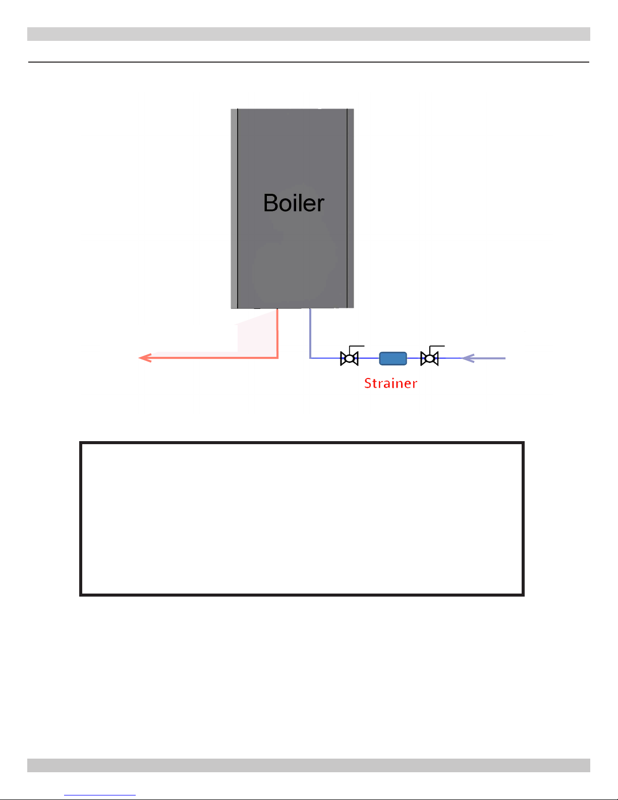
5.7 Manufacturer Recommendation - Strainer
Potable water
OUT
Potable water
IN
Manufacturer Recommendation
A strainer ltering potable water before entering the boiler is highly recommended to prevent
errors and lockouts. The stainer prevents any sedimentation and debris from your water supply
piping from entering the boiler. Debris carried from the water supply will clog DHW water ow
sensor resulting in error codes and causing boiler to lockout.
Locate the stainer as close to the boiler as possible and place on DHW (domestic hot water) inlet
connection located at bottom of the boiler.
20
240011941 REV B, [03/31/2018]
5 - HYDRONIC PIPING
5.8 Central Heating System
Boiler is designed for use in a sealed central heating system.
Design the system to operate with ow temperatures of up to
176°F (80° C), take pump head, expansion tank size, mean
radiator temperature, etc. into account.
Boiler is supplied with the following components: Pressure
relief valve - 30.0 psi (2.1 bar). Boiler internal pressure switch
will shut boiler off at 43.5 psi /3.0 bar.
Pressure gauge - to indicate the system pressure to be
maintained.
By-pass - Boiler incorporates an automatic by-pass,
However, where all radiators are tted with thermostatic
radiator valves, an external by-pass must be tted.
5.9 Domestic Hot Water Mode
Utica Boiler MAC-150 & 205 and MAH-125 & 165 with
indirect tank
!
WARNING
Burn, Scald Hazard! Water temperature over 125°F
(51°C) can cause severe burns and scalding. See
User's Manual before setting water temperature.
Failure to follow these instructions could result in death
or serious injury.
• Flow of water will operate the DHW ow switch which
requests the 3 way valve to change position. This will allow
the pump to circulate the primary water through the DHW
plate heat exchanger. (MAC-150 & 205 only)
• Combustion fan will then come on and begin to run at
ignition speed.
• Once the fan reaches ignition speed the control board will
allow power to ow to the spark generator and gas valve
creating ignition in the combustion chamber. The ame
sensor will acknowledge the presence of the ame in the
combustion chamber and send a signal to the control
board.
• Temperature sensors will send a signal to the control board
allowing the control board to increase/ decrease the speed
of the fan. The combustion fan will in turn modulate the
gas rate accordingly.
• When the domestic hot water demand ceases the burner
will extinguish, unless there is a demand for central
heating.
5.10 Frost Protection Mode
Frost protection mode is integrated into the appliance when
left in domestic hot water or central heating position. If the
temperature falls below 41°F / 5° C boiler will re on its
minimum setting until ow temperature of 86°F / 30° C is
reached.
• Priority is given to the domestic hot water supply.
Demand at tap or shower will override any central heating
requirement.
FIGURE 5-7
5.11 Pump Protection
Pump will automatically operate for 1 minute in every 24 hours
to prevent seizing.
21
240011941 REV B, [03/31/2018]

6 - COMBUSTION AIR AND VENT PIPING
!
WARNING
Fire, explosion, and asphyxiation hazard. Improper
installation could result in death or serious
injury. Read these instructions and understand all
requirements before beginning installation.
!
WARNING
ABS/PVC venting shall not to be used this product.
Use of DWV plumbing pipes to vent this boiler shall be
prohibited.
Use of cellular core PVC (ASTM F891), cellular core
CPVC, or Radel® (polyphenolsulfone) in venting
systems shall be prohibited.
Covering non-metallic vent pipe and ttings with
thermal insulation shall be prohibited.
Failure to follow these instructions could result in death
or serious injury.
Note
Follow venting manufacturer's equivalent lengths
for specialty ttings.
6.1 General
• Installations shall comply with Authority having jurisdiction
and in absence of such with:
» U.S. ANSI Z223.1 /NFPA 54 in the United States
» CSA B149.1 in Canada.
• This boiler requires a dedicated direct vent system.
• Vent connections serving appliances vented by natural draft
shall not be connected into any portion of mechanical draft
systems operating under positive pressure.
• Materials used in the U.S. shall comply with Authority
having jurisdiction and in absence of such with: ANSI/
ASTM D1785, ANSI/ASTM F441, ANSI/ASTF493, UL1738 or
ULS636.
• Canadian installations only: All venting material, primer
and glue must be listed to ULC S636.
• Venting system must be free to expand and contract.
• Vent system must have unrestricted movement through
walls, ceilings and roof penetrations.
• Check for proper joint construction when joining pipe to
ttings.
• If vent is penetrating ceilings and oors, openings must
have means of re stopping in joist areas and proper
restop spacer assemblies installed.
• Standard roof ashing methods must be used to install roof
ashing.
• Frame wall and roof openings to provide support for
attachment of termination assemblies.
• Support piping in accordance with pipe manufacturer's
instruction and authority having jurisdiction. In absence
of manufacturer's instruction use pipe hooks, pipe straps,
brackets, or hangers of adequate and strength located
at intervals of 4 ft (1.2m) or less. Allow for expansion/
contraction of pipe.
• Support horizontal sections of vent pipe to prevent sags
capable of accumulating condensate.
• Assemble vent materials in accordance with venting
manufacturer’s instructions.
• Slope exhaust pipe minimum of 1/4” per foot, or vent
manufacturer’s recommendation, whichever is greater;
back toward the boiler.
• Any "in line" elbows in ue system must be taken into
consideration. First elbow on the top of the boiler is
included in equivalent length calculations.
6.2 Removal of Existing Boiler From Common Vent
System
When existing boiler is removed from common venting
system, common venting system is likely to be too large for
proper venting of appliances remaining connected to it.
After removal of existing boiler, following steps shall be
followed with each appliance remaining connected to common
venting system placed in operation, while other appliances
remaining connected to common venting system are not in
operation:
• Seal any unused openings in common venting system.
• Visually inspect venting system for proper size and
horizontal pitch. Determine there is no blockage or
restrictions, leakage, corrosion and other deciencies which
could cause an unsafe condition.
• When practical, close all building doors, windows, and
all doors between space in which appliances remaining
connected to common venting system are located and
other spaces of building. Turn on clothes dryer and any
appliance not connected to common venting system.
Turn on exhaust fans, such as range hoods and bathroom
exhaust so they will operate at maximum speed. Do not
operate summer exhaust fan. Close replace dampers.
• Turn on appliance being inspected. Follow lighting
instructions. Adjust thermostat so appliances will operate
continuously.
• Test for spillage at draft hood relief opening after 5
minutes of main burner operation. Use ame of match or
candle, smoke from cigarette, cigar or pipe.
• Determine each appliance remaining connected to common
venting system properly vents when tested as outlined
above. Then return doors, windows, exhaust fans and any
other gas-burning appliance to their previous condition of
use.
• Any improper operation of common venting system
should be corrected so installation conforms with National
Fuel Code, ANSI Z223.1/NFPA 54 and/or Natural Gas
and Propane Installation Code, CAN/CSA B149.1. When
re-sizing any portion of common venting system, common
venting system should be re-sized to approach minimum
size as determined using appropriate tables in Chapter 13
of the National Fuel Gas Code, ANSI Z223.1/NFPA 54 and/
or Natural Gas and Propane Installation Code, CAN/CSA
B149.1.
22
240011941 REV B, [03/31/2018]
6 - COMBUSTION AIR AND VENT PIPING
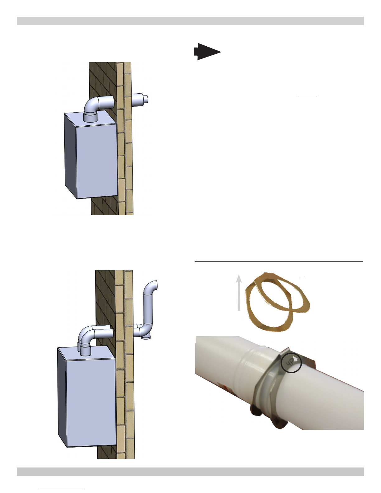
6.3 Denitions
1.
Coaxial piping – Figure 6-1 exhaust and air intake pipe
have a common axis.
2.
Twin Pipe – Figure 6-2 Exhaust and intake air are
separate pipes, can be terminated using single wall
terminals from the vent manufacturer or eld built
conguration using elbows or tees.
6.4 Securing Twin Pipe Polypropylene Venting
Note
Venting manufacturer's use a device to secure
single wall twin pipe polypropylene vent pieces
to each other. Proper application of the securing
mechanism is necessary for any use of twin pipe
polypropylene venting on exhaust or air intake.
Securing mechanism is for indoor use only and
should not be used in outdoor applications.
Follow venting manufacturer’s instructions for
applying the securing mechanism on twin pipe
polypropylene venting.
Example for Natalini venting system.
(For other venting system suppliers see their instructions.)
1.
Place clamp so etched "UP" is facing up.
2.
Open clamp slightly by separating circular areas from each
other.
3.
Slide male end of rst pipe through open clamp so the
shoulder of the female end of the pipe stops the clamp
from sliding off the pipe.
4.
Insert the male end of of the second pipe into the clamp
on the "up" etched side. Force the two pipes together.
5.
Verify the two pipes are secure together with clamp in
place.
Figure 6-3 - Natalini Clamp
UP
UP
UP
23
240011941 REV B, [03/31/2018]

6 - COMBUSTION AIR AND VENT PIPING
6.5 Approved Venting Materials
!
WARNING
Manufacturer recommends this condensing boiler be
vented with approved polypropylene venting material.
Use only materials listed below for vent pipe, intake
air pipe, and ttings. Failure to comply could result in
death or serious injury.
!
WARNING
• Covering non-metallic vent pipe and ttings with
thermal insulation shall be prohibited.
• Use of cellular core PVC for venting ue gas could
result in death, or serious injury.
• Coaxial venting shall be fastened with screws. Dual
ue venting is NOT fastened with screws.
!
WARNING
Do not use cellular core pipe. Only specied sized
pipes are to be used. When using venting material
other than boiler manufacturer's venting, note the
correct installation procedure. Failure to follow these
instructions could result in death, or serious injury.
2.
Boiler shall not support any type of vent system.
3.
All piping, glue, solvents, cleaners, ttings and
components must conform to ASTM and ANSI standards.
In Canada ULC S636 and in the USA UL 1738 schedule 40
CPVC are the only approved vent system to be used as an
alternative to polypropylene venting for the exhaust pipe
4.
Manufacturer requires use of a spring clamp at every
push-t gasket connection when using a single wall
polypropylene vent system.
6.6 Vent Termination
• Terminate combustion air and vent pipes with ttings or
coaxial vent kit.
Use horizontal pipe for vent and 90° elbow for
combustion air termination when using ttings.
• Separate vent terminal from air inlet terminal to prevent
ue gas recirculation. If T-Terminal is used on ue pipe
at sidewall, air inlet terminal shall be at least 36" or more
away from vent terminal.
• Locate combustion air termination as far as possible from
swimming pool, swimming pool pump house, and other
sources of airborne chlorine.
• Locate combustion air and vent terminals as required by
authority having jurisdiction.
Installation shall conform to requirements of authority having
jurisdiction or in absence of such requirements:
• USA - National Fuel Gas Code, ANSI Z223.1/NFPA 54.
• Canada - Natural Gas and Propane Installation Code,
CAN/CSA B149.1
1.
Venting shall be properly supported.
Vent Material Options
125 & 150 165 & 205
1 4" / 2" [100 mm / 50 mm] polypropylene coaxial. 1 5"/3" [125mm/80m] polypropylene coaxial.
3" [80mm] polypropylene twin pipe.
2
Shall be polypropylene on BOTH intake and
exhaust.
3" [80mm] exible polypropylene for chimney
3
exhaust vent, shall have rigid 3" [80mm]
polypropylene on air intake.
3" [80mm] Twin pipe CPVC.
4
PVC optional on intake ONLY.
Approved Polypropylene Manufacturers
* Natalini
* DuraVent
*Centrotherm
* Z-Flex
Note: Maximum equivalent length may vary between
manufacturers.
3" [80mm] polypropylene twin pipe.
2
Shall be polypropylene on BOTH intake and
exhaust.
2" [50mm] polypropylene twin pipe.
3
Shall be polypropylene on BOTH intake and
exhaust.
3" [80mm] exible polypropylene for chimney
4
exhaust vent, shall have rigid 3" [80mm]
polypropylene on air intake.
3" [80mm] Twin pipe CPVC.
5
PVC optional on intake ONLY.
®
®
* Note: Adapters and ttings used with all vent systems shall be from same manufacturer and compatible with the vent
pipe. See list for approved Manufacturers.
24
240011941 REV B, [03/31/2018]

6 - COMBUSTION AIR AND VENT PIPING
6.7 Coaxial Venting Instructions
Maximum equivalent ue lengths for Coaxial venting are:
Coaxial Pipe Maximum Vent Lengths
Boiler Size 125/150 165/205
Vent Size
4"/2"
[100mm/60mm]
5"/3"
[128mm/80mm]
Natalini 32.80 ft [10m] 32.80 ft [10m]
DuraVent
®
27.88 ft [8.5m] 32.80 ft [10m]
Centrotherm 24.60 ft [7.5m] 32.80 ft [10m]
Coaxial Elbows - Equivalent length
4"/2" [100mm/60mm]
45°
90°
1.64 ft. [0.5m]
3.28 ft. [1.0m]
5” / 3” [128mm/80mm]
45°
90°
1.64 ft. [0.5m]
3.28 ft. [1.0m]
NOTE: Coaxial venting can run horizontal or vertical.
• Connect ue elbow to top of boiler and adjust direction of
elbow to desired orientation (rear, right or left).
• Measure distance from outside wall face to elbow, this
dimension will be known as 'X", add distance "Y" + 2"
(50mm) to "X" this is the total dimension of the vents. See
Figure 6.4.
• Mark dimension from above on outer aluminum intake
vent. Measure length of waste material, and transfer
dimension to inner grey ue pipe.
• Remove waste from both vents (ue and air). Verify cut
ends are square and free from burrs. Insert ue back into
intake air vent and pass them through hole in wall.
• Check all measurements before cutting. Clearance to
combustible materials is zero when using coaxial vent
system.
• After installing venting use calibrated analyzer to verify
there is no recirculation of combustion.
• Ensure termination is positioned with slots at the bottom.
FIGURE 6-3 - Coaxial Vertical Exhaust
12" (305mm) Minimum
Separation
Manufacturer
Recommends
Greater Separation
FIGURE 6-4 - Coaxial Venting Horizontal or Vertical
WT
(X)
(X)
Wall Thickness
WT = Wall Thickness
FIGURE 6-5 Side Wall Coaxial Venting
18" Vertical
Clearance to
ventilated soft
2” (50 mm)
X
Min. 8" (181 mm)
Max. 14" (356 mm)
Maintain 12"(305mm)
US (18"(457mm)
Canada) clearance
above highest
anticipated snow level
24" (610mm) above
roof or ground
Anticipated
Snow Line
Ground
FIGURE 6-6 Roof Mount Coaxial Venting
Maintain 12"(305mm)
US (18"(457mm)
Canada) clearance
above highest
Anticipated
Snow Line
anticipated snow level
24" (610mm) above
roof or ground
25
240011941 REV B, [03/31/2018]
6 - COMBUSTION AIR AND VENT PIPING
6.8 Twin Pipe Systems
Twin pipe venting allows exhaust ue and intake ue to be
separated from each other. Fresh air is drawn in at a different
area from the ue terminal location.
A.
Twin Pipe CPVC System
CPVC is approved for boiler exhaust. CPVC or PVC are both
approved for air intake.
To transition from Coaxial at the top of the boiler to Twin Pipe
CPVC/PVC a kit is available.
B.
Twin Pipe Polypropylene System
Single wall polypropylene is used for both exhaust and air
intake piping.
To transition from Coaxial at the top of the boiler to Twin Pipe
polypropylene venting an adapter kit is available.
C.
Twin Pipe Separated Flue
Exhaust and combustion air intake are not located in same
general location.
D.
Twin Pipe - Common Atmospheric Zone
Termination
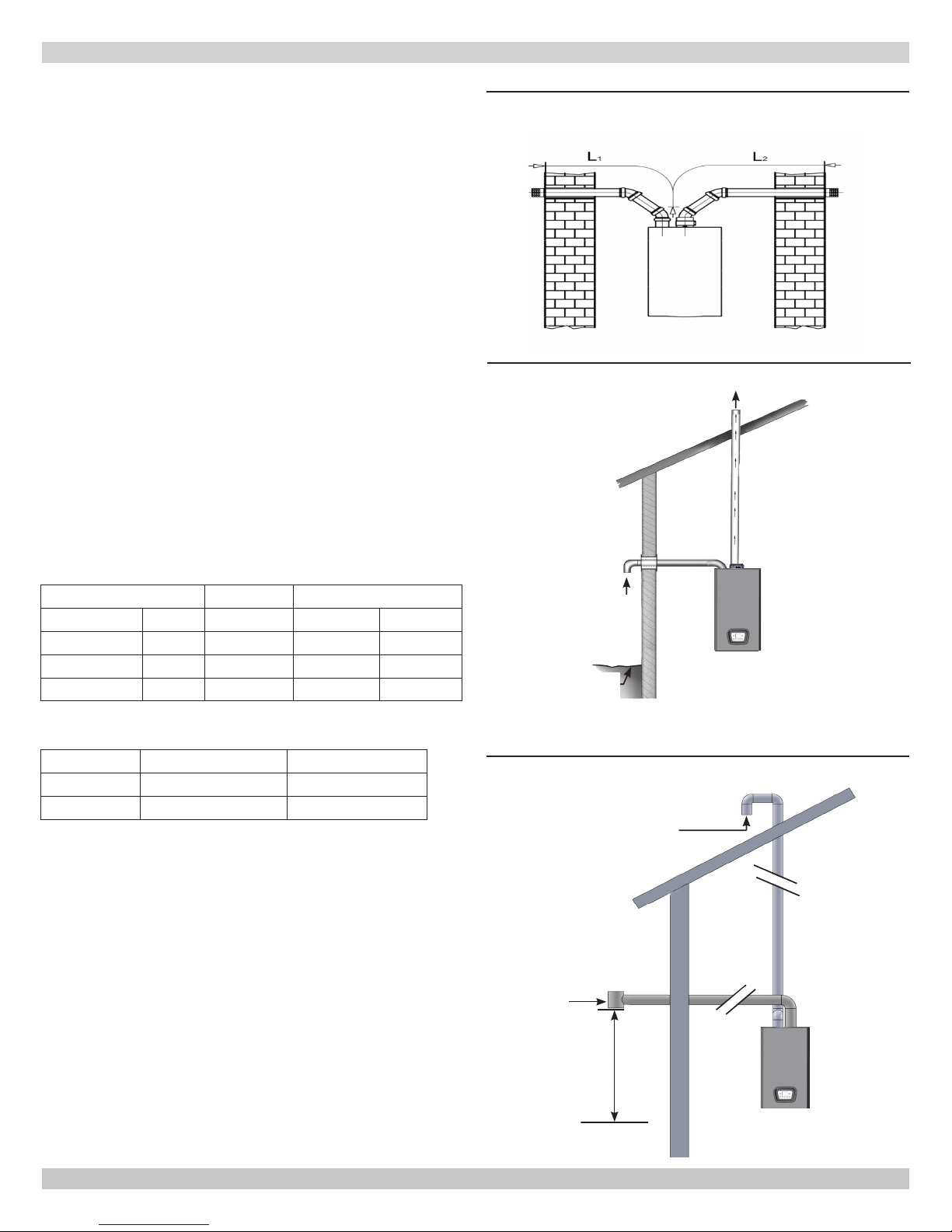
FIGURE 6-7 - Twin Pipe Separated Horizontal Flue
Termination
FIGURE 6-8 - Twin Pipe on Roof Combustion Air On
Sidewall
Vent Terminal
Twin Pipe Maximum Vent Lengths
Intake Vent L1 49 ft 100 ft 85 ft
Exhaust Vent L2 51 ft 100 ft 85 ft
Combined Vent L1+L2 100 ft 200 ft 170 ft
Single Wall Elbows - Equivalent Length
45° bend
90° bend
0.82 ft [0.25 m] 3 ft [0.91m]
1.64 ft [0.50 m] 5 ft [1.5 m]
125/150 165/205
3" [80 mm] 3" [80 mm] 2" [ 50 mm]
3" 2"
NOTE: Two pipe separated ue can run horizontal or vertical.
Combustion Air
Ground
Level
FIGURE 6-9 - Twin Pipe Flue On Sidewall, Combustion
Air On Roof
Combustion Air
Vent - T Terminal
26
12" (305mm)
Anticipated Snow Line
240011941 REV B, [03/31/2018]
 Loading...