

UTICA BOILERS MAGB Installation Manual And Operating Instructions

MAGB
MODULAR GAS FIRED BOILERS
FOR FORCED HOT WATER
Utica Boilers P.O. Box 4729 Utica, NY 13504
INSTALLATION MANUAL AND OPERATING INSTRUCTIONS

TABLE OF CONTENTS
Safety Symbols & Warnings .................................................................................. Page 2
Engineering and Dimensional Data................................................................. Pages 3-4
Typical Lay-Out for Gas Fired Systems ............................................................... Page 5
Supply and Return Piping ................................................................................... Pages 6
Installation Procedure ......................................................................................... Pages 7
Ventilation and Combustion Air ..................................................................... Pages 8-10
Vent Installation .................................................................................................. Page 10
Vent Damper Installation and Instructions.......................................................... Page 11
Vent System Modification ................................................................................... Page 12
Connecting Boilers with Refrigeration Systems ................................................ Pages 13
Connecting Gas Service .................................................................................... Page 14
Electrical Wiring.................................................................................................. Page 15
Thermostat Installation ........................................................................................Page 15
Lighting Instructions .................................................................................... Pages 15018
Normal Sequence of Operation ........................................................................... Page 18
General Instructions .................................................................................... Pages 19-21
Checking Gas Input Rate to Boiler ..................................................................... Page 21
Controls ............................................................................................................... Page 22
Wiring Diagram................................................................................................. Pages 23
Replacement Parts List and General Assembly .......................................... Pages 24-30
KEEP THIS MANUAL NEAR BOILER
RETAIN FOR FUTURE REFERENCE
SERIES MAGB
CAST IRON
GAS FIRED BOILERS
INSTALLATION MANUAL AND OPERATION INSTRUCTIONS
Published February 1995
Printed in USA
Made In USA
PAGE 1

Safety Symbols
The following defined symbols are used throughout this manual to notify the
reader of potential hazards of varying risk levels.
DANGER
DANGER - Indicates an imminently hazardous situation which, if not avoided, WILL
result in death or serious injury.
WARNING
WARNING - Indicates a potentially hazardous situation which, if not avoided, COULD
result in death or serious injury
CAUTION
CAUTION - Indicates a potential hazardous situation which, if not avoided, MAY result
in minor or moderate injury. It may also be used to alert against unsafe practices.
IMPORTANT!
1. READ ALL INSTRUCTIONS BEFORE INSTALLING.
2. To the owner: Installation and service of this boiler must be performed by a qualified
installer.
3. To the installer: Leave all instructions with the boiler for future reference.
WARNING!
1. Keep boiler area clear and free from combustible materials, gasoline and other
flammable vapors and liquids.
2. DO NOT obstruct air openings to the boiler room.
3. Modification, substitution or elimination of factory equipped, supplied or specified
components may result in property damage, personal injury or the loss of life.
4. When this product is installed in the Commonwealth of Massachusetts the installation
must be performed by a Licensed Plumber or Licensed Gas Fitter.
PAGE 2
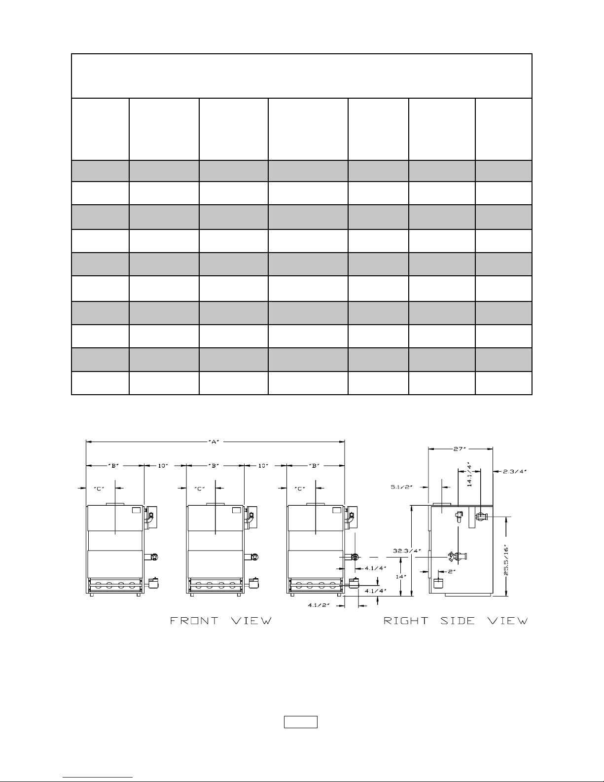
SERIES MAGB GAS FIRED BOILERS
ENGINEERING DIMENSIONAL DATA
MODEL NUMBER SHIPPING WATER ABC
NUMBER OF WEIGHT CONTENT INCHES INCHES INCHES
MAGB MODULES (LBS.) (GALLONS)
500 2 945 17.6 62.250" 26.625" 13.313"
600 2 1065 20.8 70.000" 30.500" 15.250"
750 3 1400 26.4 97.875" 26.625" 13.313"
900 3 1600 31.2 109.500" 30.500" 15.250"
1000 4 1890 35.2 133.500" 26.625" 13.313"
1200 4 2135 41.6 149.000" 30.500" 15.250"
1500 5 2665 52.0 188.000" 30.500" 15.250"
1800 6 3200 62.4 228.000" 30.500" 15.250"
2100 7 3730 72.8 267.500" 30.500" 15.250"
2400 8 4265 83.2 307.000" 30.500" 15.250"
PAGE 3
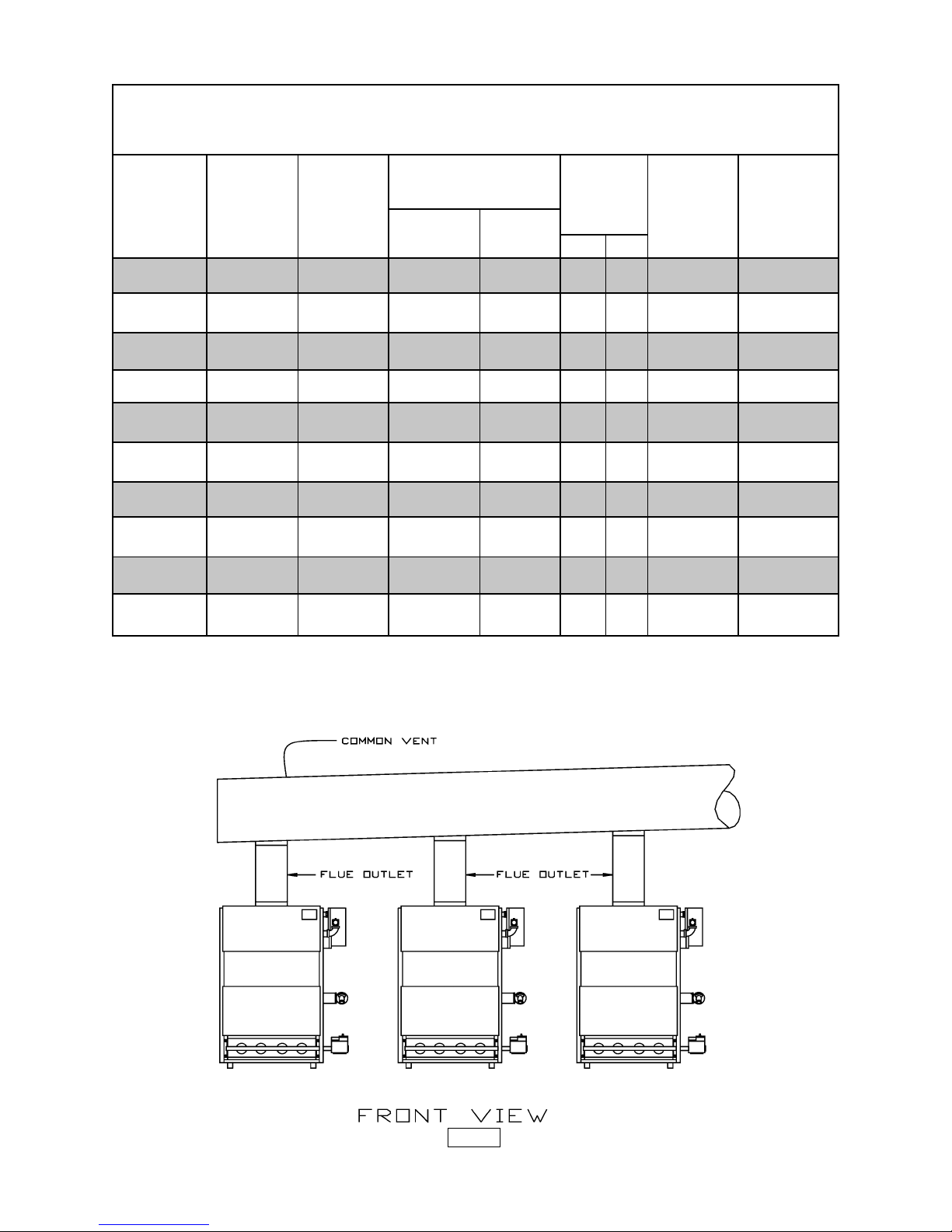
SERIES MAGB GAS FIRED BOILERS
ENGINEERING DIMENSIONAL DATA
MODEL AGA AGA NET I=B=R FLUE COMMON CHIMNEY
NUMBER INPUT OUTPUT WATER RATINGS OUTLET VENT DIAMETER
MAGB BTU/HR. BTU/HR. BTU/HR. SQ. FT. DIA.&NO. DIA. & HEIGHT
** 8" 9"
500 500,000 *410,000 356,500 2,377 2 10" 12" X 15'
600 600,000 480,000 423,000 2,817 2 12" 14" X 15'
750 750,000 *615,000 533,000 3,553 3 12" 14" X 20'
900 900,000 720,000 634,000 4,226 3 14" 16" X 20'
1000 1,000,000 *820,000 713,000 4,753 4 14" 16" X 20'
1200 1,200,000 960,000 845,000 5,635 4 16" 18" X 20'
1500 1,500,000 1,200,000 1,057,000 7,043 5 16" 20" X 20'
1800 1,800,000 1,440,000 1,268,000 8,452 6 18" 20" X 30'
2100 2,100,000 1,680,000 1,479,000 9,861 7 20" 22" X 30'
2400 2,400,000 1,920,000 1,690,000 11,289 8 22" 24" X 30'
* DOE HEATING CAPACITY
**For elevations above 2000 feet ratings should be reduced at a rate of 4% for each
1000 feet above sea level.
**For equivalent square feet of radiation, divide I=B=R output by 150.
PAGE 4

TYPICAL LAY-OUTS FOR
GAS FIRED SYSTEMS
PAGE 5
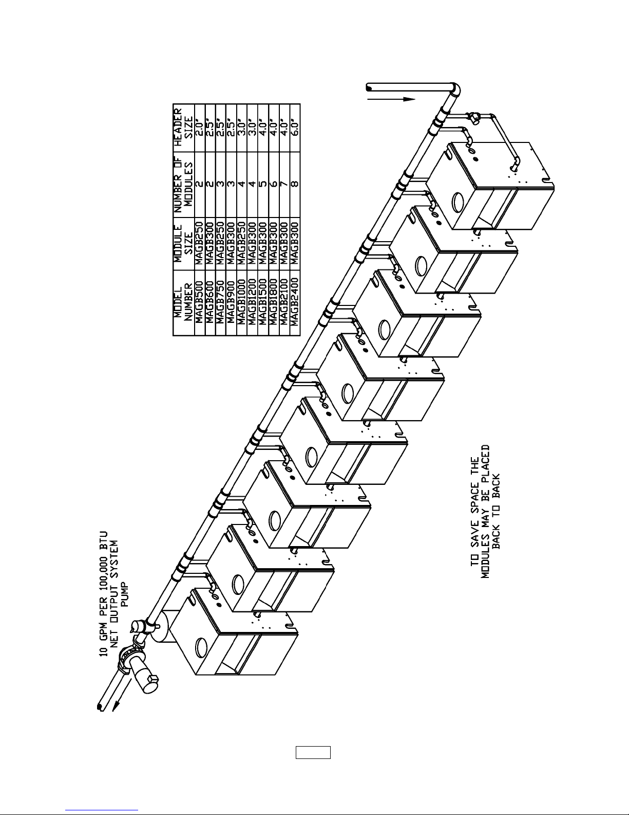
SUPPLY AND RETURN PIPING
PAGE 6

INSTALLATION PROCEDURE
WARNING: Improper installation, adjustment, alteration, service or mainte-
nance can cause injury or property damage.
1. The installation must conform to the requirements of the authority having jurisdiction
or, in the absence of such requirements, to the latest revision of the National Fuel Gas Code,
ANSI Z223. (Available from the American Gas Association, 8501 E. Pleasant Valley Road,
Cleveland, Ohio 44134). Reference should also be made to local gas utility regulations and
other codes in effect in the area in which the installation is to be made.
2. Where required by the authority having jurisdiction, the installation must conform to
American Society of Mechanical Engineers Safety Code for Controls and Safety Devices
For Automatically Fired Boilers, No.CSD-1.
3. This boiler series is classified as a Category 1 and the vent installation shall be in
accordance with Part 7 of the National Fuel Gas Code noted above or applicable provisions
of the local building codes.
4. This boiler has met safe lighting and other performance criteria with the gas manifold
and control assembly on the boiler per the latest revision of ANSI Z21.13.
5. The boiler shall be installed such that the gas ignition system components are
protected from water (dripping, spraying, rain, etc.) during appliance operation and service,
(circulator replacement, condensate trap, control replacement, etc.).
6. LOCATE BOILER on level, solid base as near the chimney as possible and centrally
located with respect to the heat distribution system as practical.
7. Allow 24 inches at the front and right side for servicing and cleaning.
8. When installed in a utility room, the door should be wide enough to allow the largest
boiler part to enter, or to permit replacement of another appliance such as a water heater.
9. FOR INSTALLATION ON NON-COMBUSTIBLE FLOORS ONLY *. The boiler must
not be installed on carpeting. Minimum clearances to combustible construction are:
TOP ................................. 18 IN.
FRONT ............................ ALCOVE
FLUE CONNECTOR ....... 6 IN.
REAR .............................. 4 IN.
CONTROL SIDE ............. 9 IN.
OTHER SIDE .................. 3 IN.
NOTE: Greater clearances for access should supersede fire protection clearances.
* For installation on combustible flooring special base part no. 325-2-8.00 must be used.
10. The MEA number for this boiler series is 19-79 Vol. II.
PAGE 7
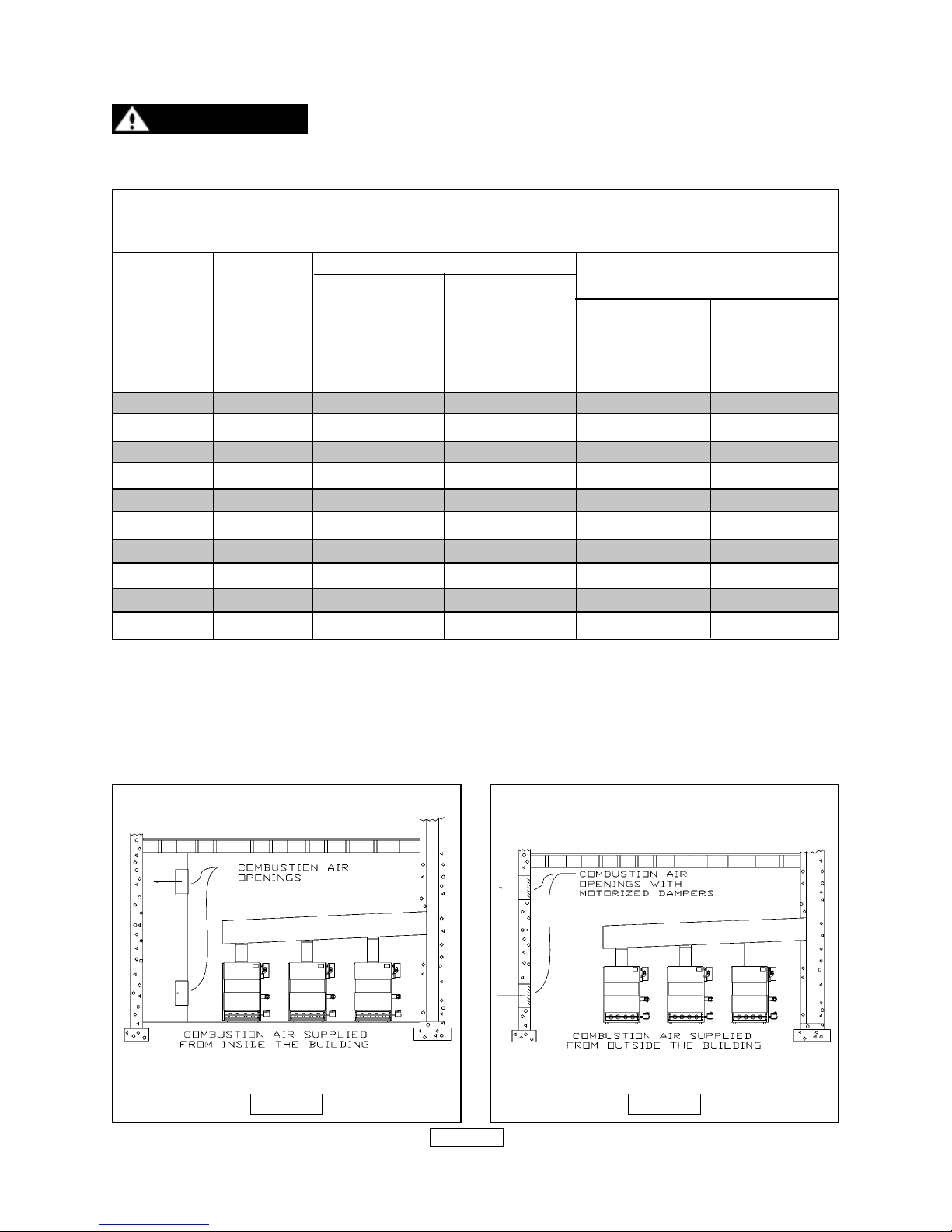
VENTILATION AND COMBUSTION AIR
WARNING: AIR OPENINGS TO COMBUSTION AREA MUST NOT
BE OBSTRUCTED. BY FOLLOWING THE CHART BELOW, ADEQUATE
COMBUSTION AIR CAN BE MAINTAINED.
COMBUSTION AIR REQUIREMENTS
(MINIMUM SQUARE INCHES OPENING)
*UNCONFINED AREA **CONFINED AREA
OUTSIDE INSIDE OUTSIDE COMBUSTION AIR
MODEL NUMBER COMBUSTION COMBUSTION VERT. DUCTS HORZ. DUCTS
NUMBER OF AIR 1 SQ. IN AIR 1 SQ. IN. 1 SQ. IN. 1 SQ. IN.
MAGB MODULES /4000 BTU/HR /1000 BTU/HR /4000 BTU/HR /2000 BTU/HR
(SEE FIG. 2) (SEE FIG. 1)
500 2 125 500 125 250
600 2 150 600 150 300
750 3 188 750 188 375
900 3 225 900 225 450
1000 4 250 1000 250 500
1200 4 300 1200 300 600
1500 5 375 1500 375 750
1800 6 450 1800 450 900
2100 7 525 2100 525 1050
2400 8 600 2400 600 1200
* Unconfined area: A space whose volume is not less than 50 cubic feet per
1000 BTU per hour of all appliances installed in that space (cubic feet of space = height
x width x length).
** Confined area: A space whose volume is less than 50 cubic feet per 1000
BTU per hour of all appliances installed in that space (cubic feet of space = height x
width x length).
FIGURE 1
FIGURE 2
PAGE 8

VENTILATION & COMBUSTION CONTINUED
1. Ventilation of the boiler room must be adequate to provide sufficient air to properly
support combustion per the latest revision of the National Fuel Gas Code, ANSI Z223.1
section 5.3.
2. When a boiler is located in an unconfined space in a building or conventional construction
frame, masonry or metal building, infiltration normally is adequate to provide air for
combustion and ventilation. However, if the equipment is located in a building of unusually tight
construction (See the national Fuel Gas Code, Ansi Z223.1 section 1.7), the boiler area
should be considered as a confined space. In this case air for combustion and ventilation shall
be provided according to part 5 on page 4. If there is any doubt, install air supply provisions
in accordance with the latest revision of the National Fuel Gas Code.
3. When a boiler is installed in an unconfined space, in a building of unusually tight
construction, air for combustion and ventilation must be obtained from outdoors or from
spaces freely communicating with the outdoors. A permanent opening or openings having a
total free area of not less than 1 square inch per 5,000 BTU per hour of total input rating of
all appliances shall be provided. Ducts may be used to convey makeup air from the outdoors
and shall have the same cross-sectional area of the openings to which they are connected.
4. When air for combustion and ventilation is from inside buildings, the confined space shall
be provided with two permanent openings, one starting 12 inches from the top and one 12
inches from the bottom of the enclosed space. Each opening shall have a minimum free area
of 1 square inch per one thousand (1000) BTU per hour of the total input rating of all appliances
in the enclosed space, but must not be less than one hundred (100) square inches. These
openings must freely communicate directly with other spaces of sufficient volume so that the
combined volume of all spaces meets the criteria for an unconfined space. See figure 1 on
page 8.
5. When the boiler is installed in a confined space and all air is provided from the outdoors
the confined space shall be provided with one or two permanent openings according to
methods A or B. When ducts are used, they shall be of the same cross sectional area as the
free area of the area of the openings to which they connect. The minimum dimension of
rectangular air ducts shall be not less than 3 x 3 inches or 9 square inches.
A. When installing two openings, one must commence within 12 inches from the top and
the other within 12 inches from the bottom of the enclosure. The openings shall communicate
directly, or by ducts, with the outdoors or spaces (crawl or attic) that freely communicate with
the outdoors. One of the following methods must be used to provide adequate air for
ventilation and combustion.
1. When directly communicating with the outdoors, each opening shall have a
minimum free area of 1 square inch per 4,000 BTU per hour of total input rating of all
equipment in the enclosure. See figure 2 on page 8.
2. When communicating with the outdoors by means of vertical ducts, each
opening shall have a minimum free area 1 square inch per 4,000 BTU per hour of total input
rating of all appliances in the enclosed space.
3. If horizontal ducts are used, each opening and duct shall have a minimum free
PAGE 9
 Loading...