

Page 1
Features
■ Low current consumption, in order to allow the
parallel operation of 4 devices
■ Integrated rectifier bridge with zener diodes to
protect against over voltages little external
circuitry
■ Tone and switching frequencies adjustable by
external components
■ Integrated voltage and current hysteresis
Description
LS1240 is a monolithic integrated circuit designed
to replace the mechanical bell in telephone sets in
connection with an electro-acoustical converter. It
can drive directly a piezoceramic converter
(buzzer) or a dynamic loudspeaker.
The output current capability of LS1240 is higher
than the one of a standard ringer. To drive a
dynamic loudspeaker LS1240 can simply use a
decoupling capacitor, thus eliminating the usual
transformer.
No current limitation is provided on the output
stage of LS1240, so a minimum load DC of 50 Ω
is advised, in series with a proper capacitor.
LS1240
Electronic two-tone ringer
Minidip
SO8
The two tone frequencies generated are switched
by an internal oscillator in a fast sequence and
are made audible across an output amplifier in the
loudspeaker. Both tone frequencies and the
switching frequency can be externally adjusted.
The supply voltage is obtained from the AC ring
signal and the circuit is designed so that noise on
the line or variations of the ringing signal cannot
affect correct operation of the device.
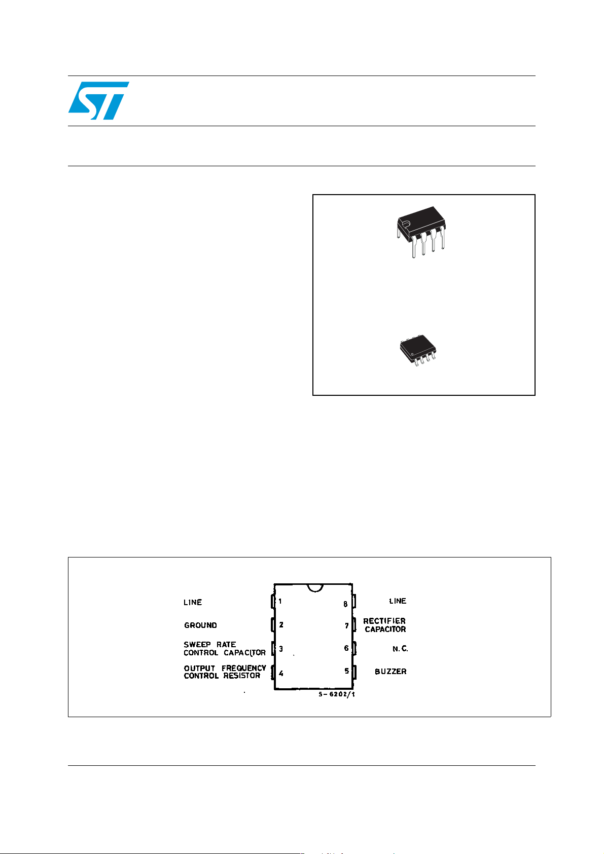
Pin connection (top view)
August 2006 Rev 2 1/9
www.st.com
9
Page 2
Block diagram and test circuit LS1240
1 Block diagram and test circuit
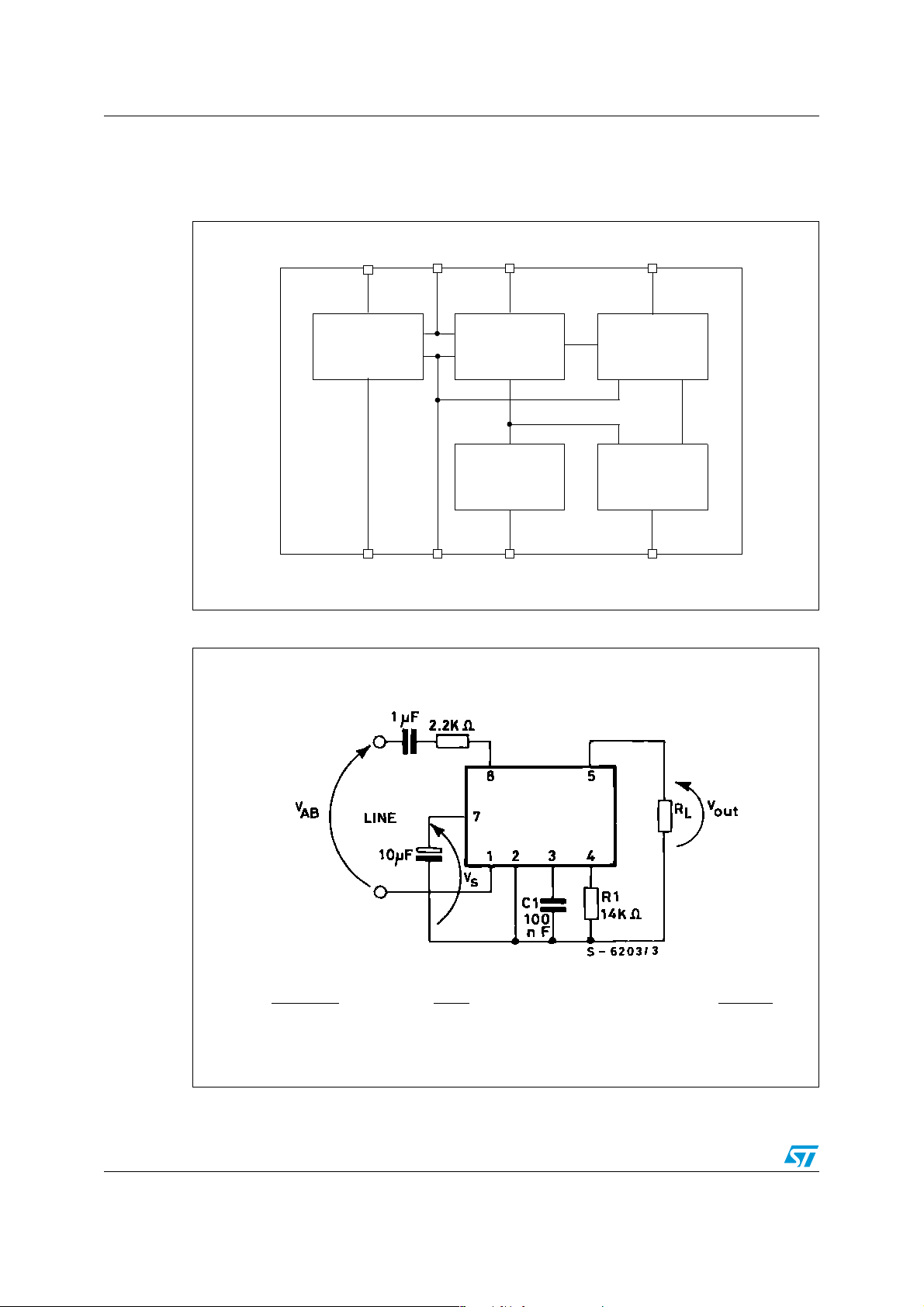
Figure 1. LS1240 block diagram
Telephone
Rectifier
bridge
Telephone
Figure 2. Test circuit
line
8
line
Rectifier
capacitor
7
+
-
GND
N.C. Buzzer
6
Threshold circuit
with hysteresis
Switching
frequency
generator
Sweep rate
control capacitor
5
Output
stage
Tone frequency
generator
4321
Output frequency
control resistor
4
⋅(1 − 0.04 ln
f1
1943
R1 =
2.72 ⋅ 10
f1 (Hz)
2/9
f2 = 0.725 f1 f
)
SWEEP
=
C1 (nF)
750
Page 3
LS1240 Electrical characteristics
2 Electrical characteristics
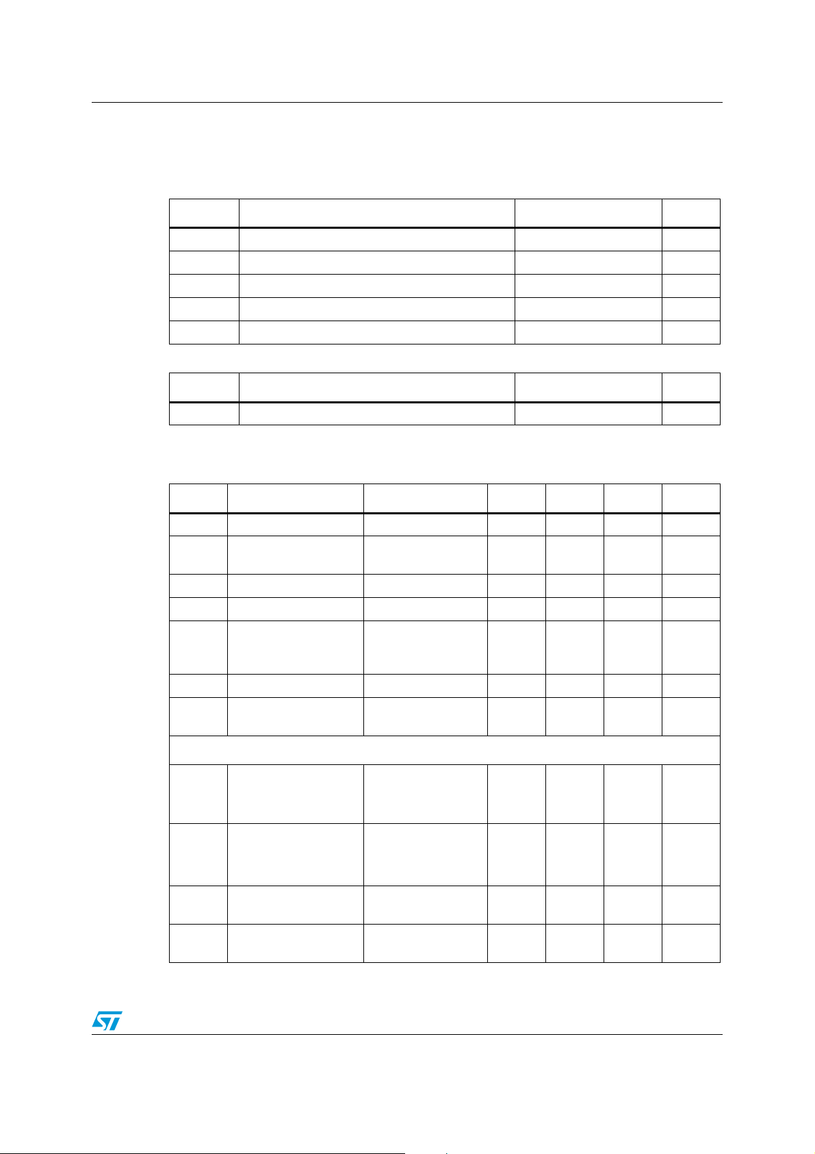
Table 1. Absolute maximum ratings
Symbol Parameter Value Unit
V
AB
V
AB
Calling voltage (f = 50 Hz) continuous 120 Vms
Calling voltage (f = 50 Hz) 5s ON/10s OFF 200 Vms
DC Supply current 30 mA
T
OP
Operating temperature -40 to 70 °C
Tstg Storage and junction temperature -65 to +150 °C
Table 2. Thermal data
Symbol Parameter Value Unit
R
thj-amb
Maximum thermal resistance junction-ambient 100 °C/W
Tamb = 25°C, VS = applied between pins 7-2 unless otherwise specified.
Table 3. Electrical characteristics
Symbol Parameter Test conditions Min. Typ. Max. unit
V
I
V
V
R
S
B
ON
OFF
D
Supply voltag e 26 V
Current consumption
without laod (pins 8-1)
V8-1 = 9.3 to 25 V 1.5 1.8 mA
Activation voltage 12.2 13.2 V
Sustaining voltage 8 9 V
Differential resistance
in OFF conditions
6.4 kΩ
(pins 8-1)
V
I
OUT
OUT
Output voltage swing VS-5 V
Short circuit current
(pins 5-2)
AC operation
Output frequencies
f
1
f
2
f
OUT1
f
OUT2
f
OUT1
----------- -
f
OUT2
Programming res ist or
range
Sweep frequency
= 20V RL = 250Ω 70 mA
V
S
VS = 26V, R1 = 14Ω
= 0V
V
V
S
= 6V
S
1.74
1.22
2.14
1.6
1.33 1.43
856kW
= 14 kΩ, C1 =
R
1
100 nF
5.25 7.5 9.75 Hz
3/9
kHz
Page 4
Application schematics LS1240
3 Application schematics
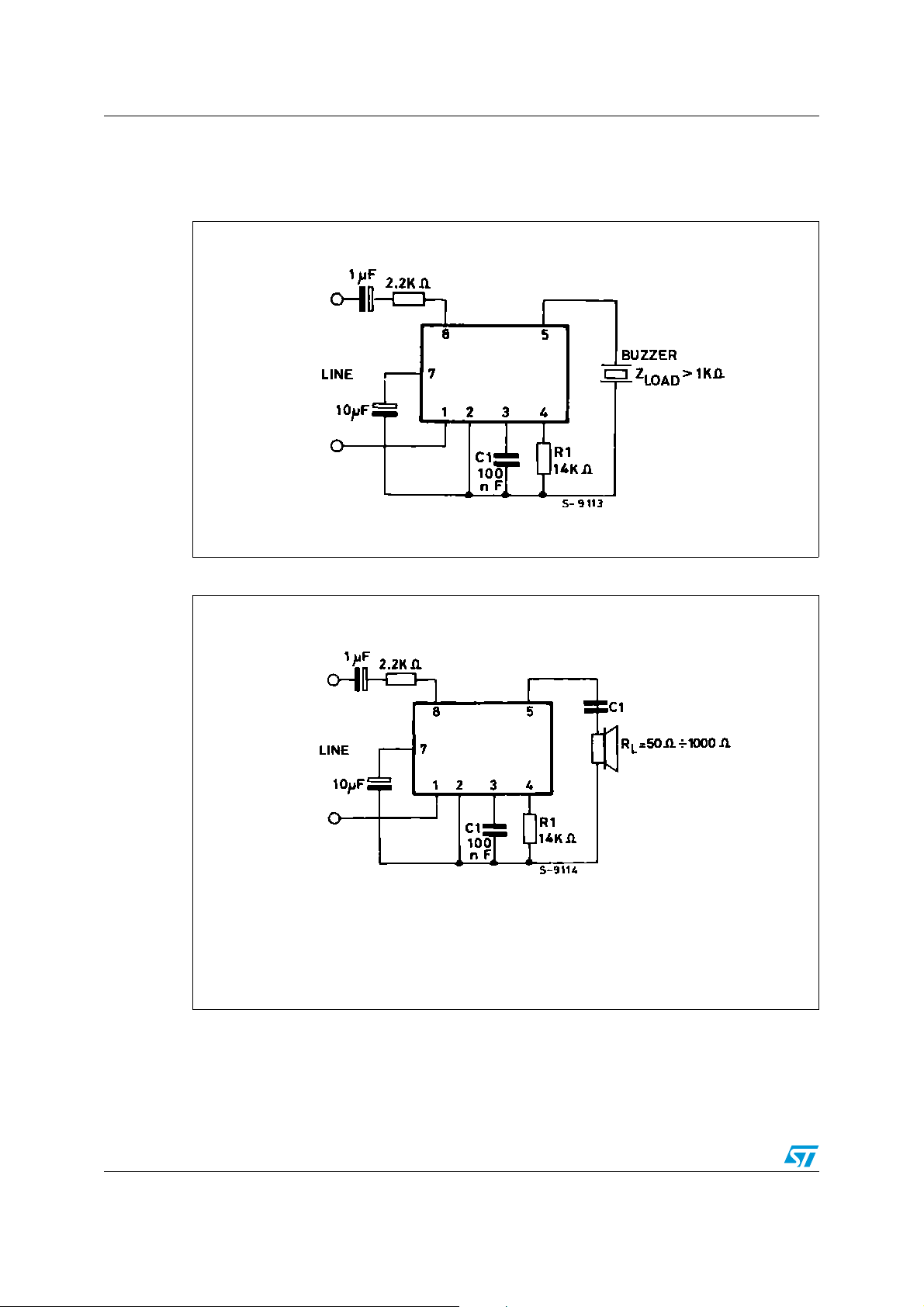
Figure 3. Typical application with buzzer
Figure 4. Typical application with loudspeaker (no transformer needed)
C1 such that ⏐Z
LOAD
⏐ > 1 ΚΩ
4/9
Page 5

LS1240 Package mechanical data
4 Package mechanical data
In order to meet environmental requirements, ST offers these devices in ECOPACK®
packages. These packages have a Lead-free second level interconnect . The category of
second Level Interconnect ismarked on the package and on the inner box label, in
compliance with JEDEC Standard JESD97. The maximum ratings related to soldering
conditions are also marked on the inner box label. ECOPACK is an ST trademark.
ECOPACK specifications are available at: www.st.com.
5/9
Page 6
Package mechanical data LS1240
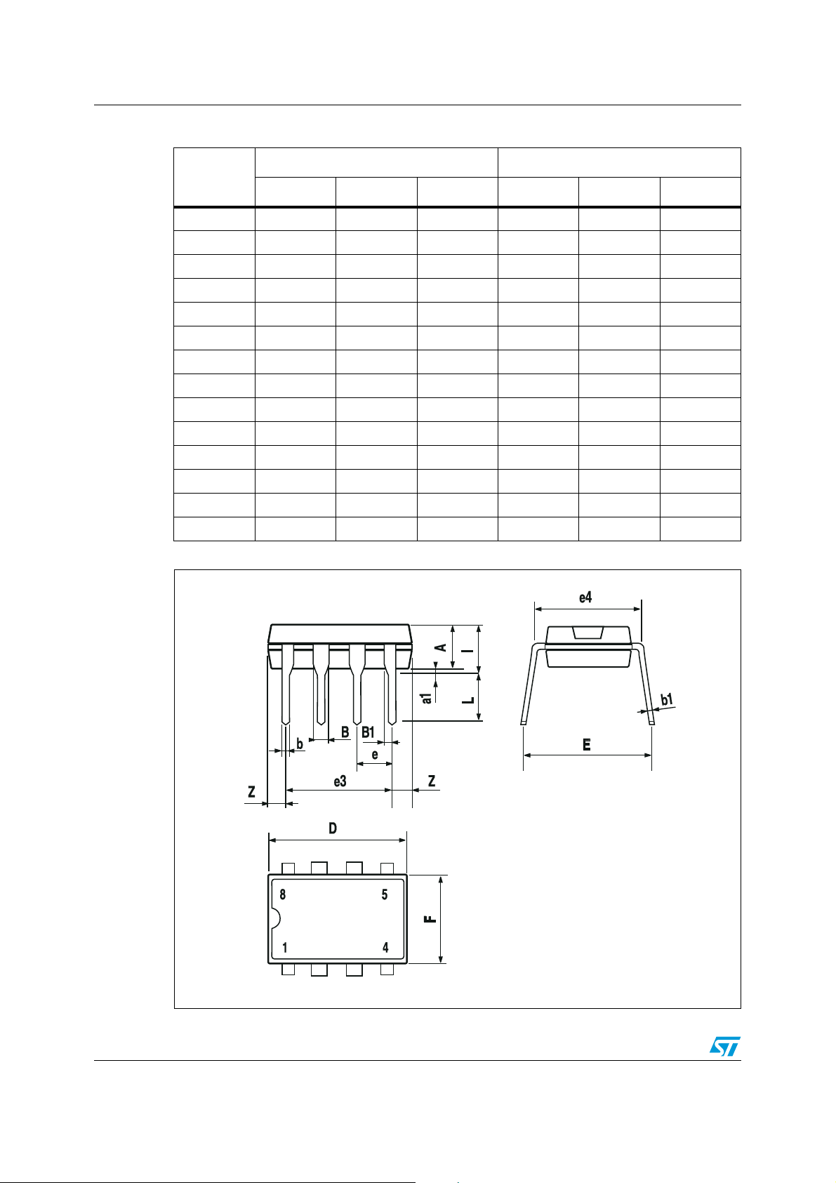
Table 4. Minidip package dimensions
mm inch
Dim.
Min. Typ. Max. Min. Typ. Max.
A 3.32 0.131
a1 0.51 0.020
B 1.15 1.65 0.045 0.065
b 0.356 0.55 0.014 0.022
b1 0.204 0.304 0.008 0.012
D 10.92 0.430
E 7.95 9.75 0.313 0.384
e 2.54 0.100
e3 7.62 0.300
e4 7.62 0.300
F6.60.260
I 5.08 0.200
L 3.18 3.81 0.125 0.150
Z 1.52 0.060
Figure 5. Minidip package mechanicla drawing
6/9
Page 7
LS1240 Package mechanical data
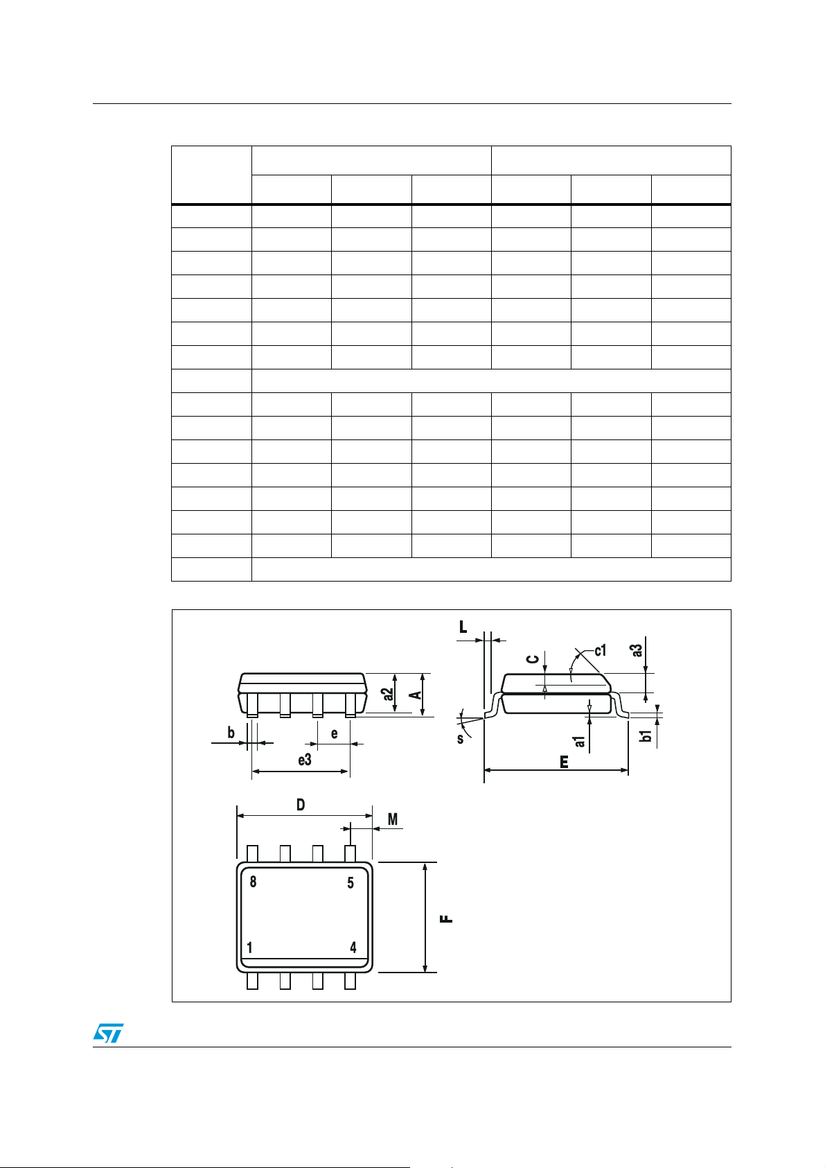
Table 5. SO8 package dimensions
mm inch
Dim.
Min. Typ. Max. Min. Typ. Max.
A 1.75 0.069
a1 0.1 0.25 0.004 0.010
a2 1.65 0.065
a3 0.65 0.85 0.026 0.033
b 0.35 0.48 0.014 0.019
b1 0.19 0.25 0.007 0.010
C 0.25 0.50 0.010 0.020
c1 45° (typ.)
D(1) 4.8 5.0 0.189 0.197
E 5.8 6.2 0.228 0.244
e 1.27 0.050
e3 3.81 0.150
F(1) 3.8 4.0 0.15 0.157
L 0.4 1.27 0.016 0.050
M0.60.024
S8° (max.)
Figure 6. SO8 mechanical drawing
7/9
Page 8
Ordering information LS1240
5 Ordering information
Table 6. Order codes
Part number Package
LS1240A Minidip
LS1240AD1 SO8
E-LS1240A
E-LS1240AD1
(1)
(1)
Minidip
SO8
1. ECOPACK® (see
Chapter 4
)
6 Revision history
Table 7. Document revision history
Date Revision Changes
15-Jul-1998 1 Initial release.
23-Aug-2006 2
Updated the document to reflect the fact that packages are leadfree
and part numbers have changed.
8/9
Page 9

LS1240
Please Read Carefully:
Information in this document is provided sole ly in connecti on with ST produ cts. STMicro electroni cs NV and its subsi diaries (“ST ”) reserve the
right to make changes , cor recti ons , modif ic ations or improv ement s, t o th is documen t, and the prod ucts an d servic es des crib ed he rein a t any
time, without notice.
All ST products are sold pursuant to ST’s terms and conditions of sale.
Purchasers are solely responsible for the choice, selection and use of the ST products and services described herein, and ST assumes no
liability whatsoever rel ating to the choice, selection or use of the ST products and services described herein.
No license, express or implied, by estoppel or otherwise, to any intellectual property rights is granted under this document. If any part of this
document refers to any third party products or services it shall not be deemed a license grant by ST for the use of such third party products
or services, or any intellectual property contained therein or considered as a warranty covering the use in any manner whatsoever of such
third party products or services or any intellectual property contained therein.
UNLESS OTHERWISE SET FORTH IN ST’S TERMS AND CONDITIONS OF SALE ST DISCLAIMS ANY EXPRESS OR IMPLIED
WARRANTY WITH RESPECT TO THE USE AND/OR SALE OF ST PRODUCTS INCLUDING WITHOUT LIMITATION IMPLIED
WARRANTIES OF MERCHANTABILITY, FITNESS FOR A PARTICULAR PURPOSE (AND THEIR EQUIVALENTS UNDER THE LAWS
OF ANY JURISDICTION), OR INFRINGEMENT OF ANY PATENT, COPYRIGHT OR OTHER INTELLECTUAL PROPERTY RIGHT.
UNLESS EXPRESSLY APPROVED IN WRITING BY AN AUTHORIZED ST REPRESENTATIVE, ST PRODUCTS ARE NOT
RECOMMENDED, AUTHORIZED OR WARRANTED FOR USE IN MILITARY, AIR CRAFT, SPACE, LIFE SAVING, OR LIFE SUSTAINING
APPLICATIONS, NOR IN PRODUCTS OR SYSTEMS WHERE FAILURE OR MALFUNCTION MAY RESULT IN PERSONAL INJURY,
DEATH, OR SEVERE PROPERTY OR ENVIRONMENTAL DAMAGE. ST PRODUCTS WHICH ARE NOT SPECIFIED AS "AUTOMOTIVE
GRADE" MAY ONLY BE USED IN AUTOMOTIVE APPLICATIONS AT USER’S OWN RISK.
Resale of ST products with prov isions differen t from the state ments and/or tec hnical featur es set forth in th is document shall immediatel y void
any warranty granted by ST for the ST product or service described herein and shall not create or extend in any manner whatsoever, a ny
liability of ST.
ST and the ST logo are trademark s or registered trademarks of ST in various countries.
Information in this document su persedes and replaces all information previously supplied.
The ST logo is a registered trade mark of STMicroelectronics. All other names are the property of their respective owners.
© 2006 STMicroelectronics - All rights reserv ed
STMicroelectronics group of companies
Australia - Belgium - Brazil - Canada - China - Czech Republic - Finland - France - Germany - Hong Kong - India - Israel - Italy - Japan -
Malaysia - Malta - Morocco - Singapore - Spain - Sweden - Switzerland - United Kingdom - United States of America
www.st.com
9/9
 Loading...