

Page 1
UStec
Residential Structured Wiring User Manual
Model Number:
Installed By
Page 2

Page 3

Glossary
System Topology
MDU series
tecReady MDU222
tecLAN MDU Basic
tecLAN MDU
iLAN MDU
400 Series for CATV
tecReady 400
tecLAN 400 Basic
tecLAN 400
iLAN 400
800 Series for CATV
tecReady 800
tecLAN 800 Basic
tecLAN 800
iLAN 800
iLAN 800 – GS
800 Series for Satellite TV & Antenna
tecSat 800 Basic
tecSAT 800
iSAT 800
850 Series for Satellite TV & CATV
tecSat 850
iSAT 850
1600 Series For CATV
tecReady 1600
tecLAN 1600 Basic
tecLAN 1600
iLAN 1600
9
15
19
19
19
20
20
23
23
23
24
24
27
27
27
28
28
29
33
33
34
34
37
37
38
41
41
42
43
44
1600 Series For Satellite / CATV or Antenna
tecSAT 1600
iSAT 1600
IntelliWAY Gateway Server
Cable Modem Hookup
DSL hookup
Satellite Television Hookup
Modulation and distributing video
46
47
49
51
53
55
61
45
Table of Contents
3
Page 4

Set Top Box note:
Satellite Internet Hookup
Two-Way Satellite
One Way Satellite
Computer Networking
Surveillance Cameras
Infrared Remote Controls
Audio Distribution
Third Party equipment examples
IP cameras
MP3 Player
The Future
UStec Modules
Panel Modules
Amplified Coax Module CX-AMP16
Amplified Coax Module CX-AMP8
Internal 8-Way CX Module CX-DM8
CX-4X4U & CX-4X4U.1 Distribution Modules
Satellite Multiswitch CX-DSS4
Satellite MultiSwitch Module CX-DSS58
Satellite MultiSwitch Module CX-HDA58
Camera Module CX-CM4
Audio Speaker Hub Module AU-2X4
Power Supply Module UX-DC6.2
TP Input Module TP-IN4RS
TP Module TP-DM10R
TP Module TP-DM6R
Computer 10/100BaseT Switch Module TP-10/100BT
Computer 10/100 Ethernet Switched Router Module TP-IPR8
Telephone Integration Module TP-KSU8
Surveillance Cameras (CMA-OBW, CMA-OC, CMA-IBW, CMA-IC)
RJ45 Universal Breakout Box UB4.5 (tecFlex Line Chooser)
UStec Basic Troubleshooting.
Telecom Issues
No Cable Television or Off-Air Signals
Ethernet Connection Issues
UStec 15-Year Performance Guarantee
64
65
65
67
69
71
73
75
79
79
79
80
81
81
83
83
84
84
85
85
86
86
87
87
88
88
89
89
90
93
93
93
94
95
89
91
92
4
UStec Structured Wiring User Manual
Page 5

Congratulations on your purchase of a UStec structured wiring system. The
technologies employed in your home allow for the utilization of numerous
advanced technologies today, and is ready for new technologies tomorrow.
We here at UStec want to thank you for the purchase and would like to welcome you to the iLife! This user guide is designed to provide you familiarity
with your system as well as provide you with some ideas to further utilize it.
Like all products at UStec, this manual will be constantly updated to better
serve you. We value and rely on your input, so if there is something you
would like to see please let us know.
Once again, Thank you.
Page 6

Page 7

Copyright Information
The information contained in this publication represents the current view
of UStec Incorporated on the date of publication. Because UStec must
respond to ever changing market conditions, UStec cannot guarantee the
accuracy of any information presented after the publication date.
This document is for informational purposes only. UStec makes no
warranties, expressed or implied, in this publication.
Other products and/or company names mentioned in this publication may
be the trademarks of their respected owners.
tecGate, tecServer, iLAN, iSAT, tecFlex, tecCenter, and iLIFE are registered
trademarks of UStec Incorporated.
UStec Incorporated 100 Rawson Rd. Suite 205 Victor, NY 14564
3/25/2002
Page 8

Page 9

Glossary
Glossary
There are some terms used throughout this manual that may need
some clarification. This section provides the basic terminology and
usage as defined in a UStec system.
Bandwidth
carry when it is correctly installed. The range of frequencies the system will
handle.
Baseband
There is no manipulation of the signal as in Broadband. An example are the
RCA outputs on your VCR.
Bonded Pairs
together during manufacturing to resist separation and exhibit greater dimensional stability.
Broadband -
with RF video systems, baseband signals are modulated to individual frequency ranges. It is the sum of all these used frequencies that refers to broadband. Broadband is also being defined in Internet terms to designate a high
bandwidth connection.
Bundled Cable
unit. UStec bundled cables are 2x2. Bundled cables are also called loomed,
speed-wrap, and whip-cable construction.
Cable Modem -
the high speed cable signal to Ethernet and or USB.
- The amount of information the telecommunications system can
- Transmitting signals sequentially in their own frequency range.
- Conductor pairs in twisted-pair cables that are bonded
Transmission of signals in a broad frequency range. Typically
- An assembly of cables “bundled” together to form one cable
A device used for cable high speed Internet access. Converts
Cat 5E cable –
ually twisted at different twist rates for performance. Category 5E is actually a
performance rating of the cable. In the bundle there is one Blue Category 5E
for telecom and one Green Category 5E for data communications.
UStec Structured Wiring User Manual
Wire consisting of 4 separate pair of wire. Each pair is individ-
9
Page 10

Cross-talk -
in the other pairs. Cross-talk is caused by the magnetic fields in one pair generating a voltage in another pair.
Data
– The connection point for Ethernet enabled devices such as computers
and IP cameras. Requires Ethernet capability in the UStec tecCenter.
DBS
– A method of delivering “cable television” from satellites in the sky.
DBS is an acronym for Direct Broadcast Satellite. DirecTV and Dish networks
are two examples.
DSL
- A medium for high speed bandwidth of a pair of copper wires. DSL is
an acronym for Digital Subscriber Line. In a residential setting the most common form of DSL is known as ADSL. Asynchronous Digital Subscriber Line.
Undesirable signal coupling to one pair in the cable from signals
EIA/TIA-568-A
to plan and install structured cabling systems, and establishes performance
and technical criteria for interfacing and connecting cable and telecommunications devices. Not to be confused with T568A which is a color code scheme.
Ethernet
Externals -
These services may include CATV, satellite TV, broadcast TV, telephone, and
high speed Internet access.
Forward Channel -
sion.
Frequency
expressed in Hertz (Hz).
Gain
- The amount of increase in signal. +3db indicates that the signal level
will be 3dB higher on the TV out ports than what went into the input. -13dB
refers to the loss of signal level that occurs going back to the headend equipment.
Gateway Server
services for the home. Currently they include Internet connection sharing, file
sharing, security, firewall protection, application serving.
- A standard for a generic cabling system; it enables installers
- A standardized way of connecting computers in a network.
Signals that enter the home from a utility or service provider.
Signals from the CATV headend or antenna to the televi-
- In alternating current, the number of cycles per second; also
- A device located in the UStec system that provides gateway
10
UStec Structured Wiring Users Manual
Page 11

Glossary
Internal – Connection port on the tecPort. It is used for sending RF modulated signals back into the system for whole house delivery. If satellite is used
in the home, it also distributes the satellite signals to the satellite receivers.
Internal Signals - Signals generated within the home and processed and distributed by the tecGate panel. The signals may be from VCRs, DVD players,
audio equipment, security cameras, and home computers.
LNB – A device situated on the front of a satellite dish that collects the weak
signals from the satellites typically at 12.2 -12.7 GHz, amplifies them and
block converts them to 950- 1450 MHz. Technically this is actually an LNBF.
An acronym for Low Noise Block converter/Feedhorn.
Network - The network is the UStec system and any connected devices to it.
That can include but is not limited to computers, satellite receivers, VCR’s,
DVD’s, televisions, or telephones. When most people think of networks, they
envision computers. Your UStec system is the next evolution of that including
all devices.
Network Camera- UStec offers a line of both indoor and outdoor color and
black and white cameras that are viewable on any television in the home.
Typical uses for them are front and rear door security cameras, as well as baby
monitoring.
NID – The Network Interface Devices is the connection point typically on the
side your home where the connections from the street services such as telephone, cable, and high speed broadband are connected to the UStec house
network. From the NID your services pass to the UStec system in your home.
Phone- The connection point for the phone on a tecPort.
Reflection - The phenomenon that occurs when an AC signal encounters a
different medium or impedance and is returned to the original medium. Also
called Return Loss
Return Channel - Signals that pass from the residence back to the service provider headend.
RF Modulator – This device is capable of taking any device with baseband
line level outputs (RCA style jacks) and turning them into a cable TV or UHF
UStec Structured Wiring User Manual
11
Page 12

television channels. For example this is useful for watching a satellite receiver
or DVD player anywhere in the house.
RG6 Coaxial Cable – Cable designed for the distribution of broadband.
UStec cable is designed and guaranteed to handle frequencies up to 2400
MHz (2.4 GHz).
RJ31X – An interface to make connections to security equipment is called the
RJ31X. The jack is an industry standard interface that allows the security/fire
panel to obtain telephone line control to notify the proper authorities.
Set Top Box- A device such as a satellite receiver or cable television company
converter box for viewing of television signals.
Standard - A specification or a set of specifications that describe the qualities
or criteria that a product or service must meet to receive the approval of an
industry association or other oversight group.
Star Topology - A system design in which the cable runs radiate outward in
the shape of a star from a central location. Each run is continuous, i.e., it has
no taps and no splices.
Structured Wiring - The process of planning and installing a high bandwidth
distribution system that transports audio, video, data, and telecommunications throughout a home.
12
T568A -Wiring method specified in EIA/TIA-568-A standard for Category 5
plugs and jacks.
tecFlex Line Chooser – Each Category 5E jack in your room locations is capable of carrying up to 4 telephone lines (numbers). The line chooser makes it
simple to connect to the line of your choice at any jack.
tecGate Server - A modular, expandable electronic gateway for the in-home
distribution of external services such as CATV, satellite TV, broadcast TV, telephone, and high speed. It is also called the tecCenter or tecPanel.
tecPort – The termination point for a tecWire bundle is at the wall plate
called a tecPort. It has 2 RG6 Coax and 2 enhanced Category 5E wires. There
are other configurations available as well such as for wall phone’s, phone
only locations, or independent data jacks.
UStec Structured Wiring Users Manual
Page 13

Glossary
tecReady/tecLAN/iLAN – This is a a model classification system to denote
features. The tecReady systems provide for basic connections, the tecLan is the
next step in line, and the iLAN is the all in wonder product.
tecWire- tecWire is a jacketed bundled cable providing 2 enhanced Category
5E cables and 2 high frequency RG 6 coaxial cables.
Topology - The physical layout of a system and how it is connected.
TV-out – The port on the tecPort that television or VCR’s are connected to.
Twisted Pair Cable - A cable in which the pairs of conductors are twisted
together in a carefully controlled manner to achieve improved electrical characteristics for high frequency signal use. The twisting helps keep radiation and
absorption to a minimum.
Unshielded Twisted Pair (UTP) Cable - A form of twisted pair cable that
does not contain a grounded conductive shield. When a signal is transmitted,
equal current flows through each of the wires in the pair, but in opposite
directions.The twisting of the pairs keeps them close together and their fields
overlap and cancel out, eliminating radiation into adjacent pairs.
UStec Structured Wiring User Manual
13
Page 14

14
UStec Structured Wiring Users Manual
Page 15

System Topology
InternalInternal
System Topology
The UStec system is designed as the heart of the electronic lifestyle in your
home. The diagram below shows how various technologies integrate with the
system. Your system may include some or all of these features.
tecCenter
Wireless Applications
72∫
Low Voltage Sensors & Control Devices
WWW:
http://
Broadcast TV
Wireless
Coaxial
CATV
Cable
Satellite
Video Dial Tone
Phone
ISDN
Twisted
DSL
Pair
ATM
Utility
Services To The Home
Power
DSM
Line
Security
d
e
d
n
e
m
m
o
l
c
e
e
v
R
e
L
l
a
n
g
i
S
t
u
p
n
I
V
m
/
B
d
0
1
n
-
O
0
r
e
w
o
/
P
V
T
A
C
C
D
V
2
1
a
n
n
te
n
A
t
u
p
In
l
l
a
a
n
n
r
r
te
te
n
n
I
I
t
TV Ou
1
.
8
P
M
A
X
C
th
a
P
n
r
u
t
e
R
e
g
r
u
S
-
r
e
i
f
i
l
p
m
A
F
R
DataTVPhone
Internal
tecPort
123456
100 Mbps
Link/Activity
10/100 BaseT Auto Sensing Switch
123456
100 Mbps
Link/Activity
10/100 BaseT Auto Sensing Switch
POWER
T
U
P
N
I
C
A
V
0
2
1
G
a
c
t
e
TPBus RJ45 Distribution Module TP-DM10R
TP-10/100BT
Cascade
Broadband
POWER
12VDC/200mA
T568A
TELCO Bus Active
TP-10/100BT
Cascade
Broadband
POWER
12VDC/200mA
T
P
B
u
s
P
r
im
a
r
y
U
T
P
I
n
p
u
t
a
P
n
e
l
P
T
-I
N
4
R
S
R
E
V
B
X
1
J
R
3
I
N
2
e
i
n
L
IN
O
C
L
E
T
A
T
1
O
C
A
D
2
O
C
5
T
A
3
O
C
1
X
3
J
R
C
e
1
i
n
L
O
U
T
4
O
C
R
E
W
O
P
T
E
L
s
u
B
E
C
C
O
N
O
F
F
O
A
m
5
0
2
/
C
D
V
1
2
1
P
T
/
0
P
T
4
O
C
/
3
O
C
T
S
E
T
A
B
C
C
B
A
S
T
U
P
T
O
U
A
m
0
5
2
/
C
D
V
2
1
z
H
0
6
/
2
.
6
C
D
-
X
U
y
l
p
p
u
S
r
e
w
o
P
r
e
v
r
e
S
e
t
Broadband Video and High Speed Data
In-Home Video Channels - VCR - Surveillance Cameras
*
Telephone - Computer Networks - Fax - Remote Controls
Power Line: Energy Management - Service Diagnostics - Automation Controls
There are four main stages to your UStec system.
•Termination cabinet (tecCenter)
•2X2 tecWire
•tecPorts
•Network attached devices.
UStec Structured Wiring User Manual
15
Page 16

When your home was wired, the UStec cabinet and 2X2 tecWire wiring systems were put in place. These are the first two of the four stages.
In the room locations the connection points called tecPorts are the third
stage.
Lastly any UStec components such as RF camera’s, IP camera’s, or your electronic components such as televisions, etc. make up the fourth component
set.
The tecCenter is the central location in your home where all the tecWires are
terminated in one location. This is the network hub. All signals that enter
your home, or are generated in the home are distributed through the UStec
tecCenter panel. This is what allows you to use an RF modulator in one room,
plug it into the internal cable and distribute to the whole home.
16
UStec Structured Wiring Users Manual
Page 17
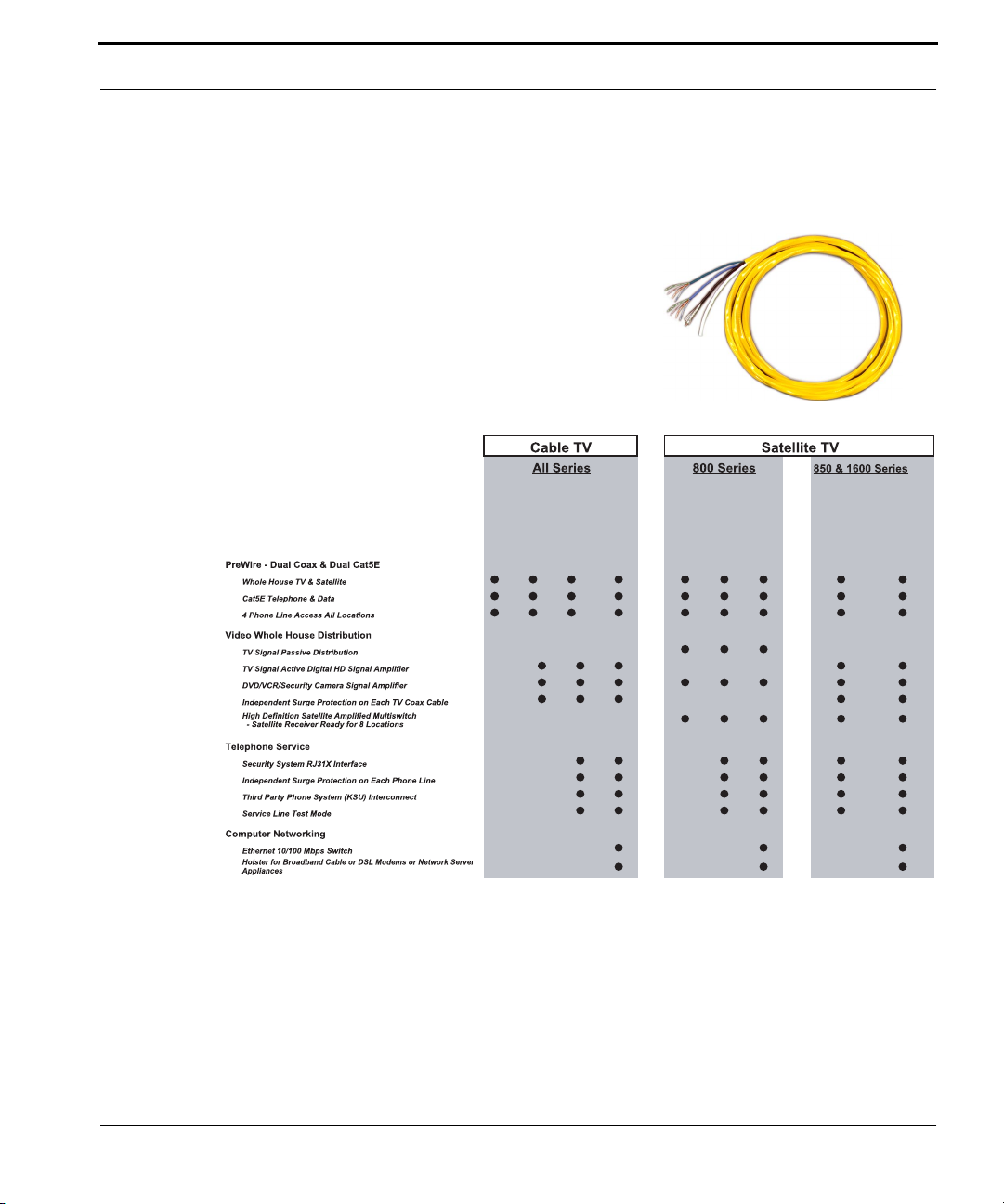
The most important part of your system is the tecWire in the walls. It is easy
to make changes to devices outside the walls, but difficult to make changes
inside them.
The tecCenter installed in your home was
chosen to meet the criteria set forth by
either the homeowner or the builder. The
following chart shows the differences
between the systems, and methods for
choosing the right system.
2X2 tecWire
tecready
tecBasic
tecSAT Basic
tecSAT
iSAT
tecSAT
iLAN
tecLAN
The next seven sections will discuss the systems based on the chart above.
Please use the images to judge your system if the installing dealer did not
write the model down on the front page of this manual.
iSAT
UStec Structured Wiring User Manual
17
Page 18

18
UStec Structured Wiring Users Manual
Page 19
MDU series
MDU series
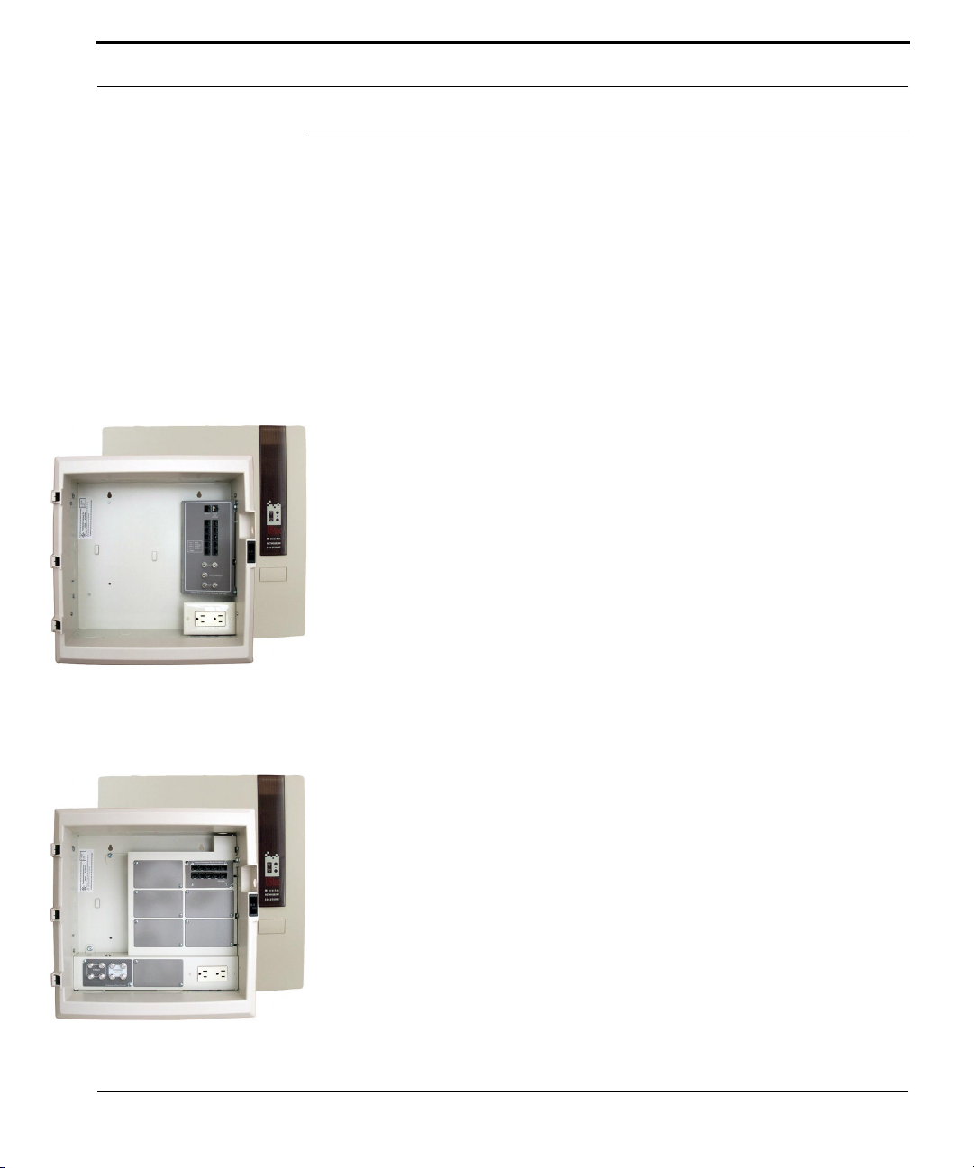
The MDU Series is designed for multi-family dwellings wired with UStec 2X2
tecWire for up to 4 multimedia tecPort locations. Each model provides a passive coaxial cable distribution for up to 4 TV’s. The tecLAN MDU Basic models and higher include a cable signal combiner with a built-in high pass filter
to eliminate potential interference with cable channels from in-home generated VCR,DVD or camera channels. Up to 10 phone locations may be provided, each with 4 phone line capacity. The optional holsters provide a
hinged mounting bracket for cable modems, DSL modems, and home server
appliances. (Holsters standard on iLAN versions)
Common to all systems is the UX-75x cabinet that houses all the wire and
tecCenter equipment. Each cabinet houses an electrical outlet in the lower
right hand corner to power UStec and third part peripherals.
Each system is enclosed in a integrated plastic cover and drywall trim kit.
Each cover can be locked with the addition of the cover locking kit, part
number UX-408.
tecReady MDU222
This system uses the UX-222 module and is designed to distribute an off-air
or cable television signal and distribute it in up 4 different locations in the
home. It can accept up to four telephone lines and distribute them to 10 different locations in the home. Additionally it has a RJ31X line grabbing inter-
face for a security panel. This system can be upgraded to any of the following
systems.
tecLAN MDU Basic
This system is designed to distribute an off-air or cable television signal up
to 4 different locations in the home. The CX-4X4U module that distributes
the off-air or cable television signals also has 4 internal inputs. The internal
ports allows for in home generated television signals to be viewable anywhere in the home. Examples might be a DVD player that you would also
like to see in the bedroom. The TP-DM10B telecom module will distribute
UStec Structured Wiring User Manual
19
Page 20
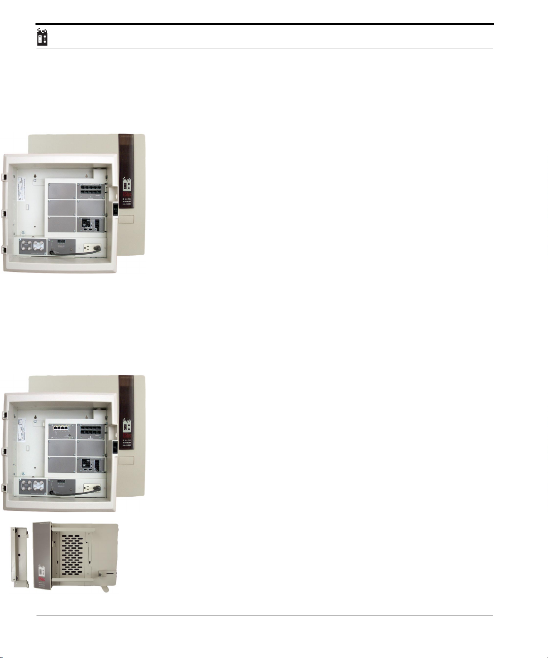
up to 4 incoming telephone lines out to 9 different locations in the home.
This device can be upgraded to any of the following MDU systems.
tecLAN MDU
This system is designed to distribute an off-air or cable television signal up to
4 different locations in the home. The CX-4X4U module that distributes the
off-air or cable television signals also has 4 internal inputs. The internal ports
allows for in home generated television signals to be viewable anywhere in
the home. Examples might be a DVD player that you would also like to see in
the bedroom.
Up to 4 incoming telephone lines are plugged into the TP-IN4RS module.
This device will surge protect all 4 incoming telephone lines and distribute
them to 10 different locations via the TP-DM10R module. Additionally the
TP-IN4RS module provides security line grabbing interfaces (RJ31X) on telephone lines 1 and 2. This module also provides a conduit to Key System telephone Units (KSU). This system can be upgraded to the following systems.
iLAN MDU
This system is designed to distribute an off-air or cable television signal up to
4 different locations in the home. The CX-4X4U module that distributes the
off-air or cable television signals also has 4 internal inputs. The internal ports
allows for in home generated television signals to be viewable anywhere in
the home. Examples might be a DVD player that you would also like to see in
the bedroom.
20
Up to 4 incoming telephone lines are plugged into the TP-IN4RS module.
This device will surge protect all 4 incoming telephone lines and distribute
them to 10 different locations via the TP-DM10R module. Additionally the
TP-IN4RS module provides security line grabbing interfaces (RJ31X) on telephone lines 1 and 2. This module also provides a conduit to Key System telephone Units (KSU).
A six port (1 is broadband connection, 1 is cascade to optional second unit)
10/100 Ethernet switch is included as well. It provides for the connection of
up to 4 different computers in addition to a broadband sharing device that is
mounted in the included gateway holster.
UStec Structured Wiring Users Manual
Page 21

MDU series
The flexible holster design is capable of handling a host of broadband devices
from cable modem routers, xDSL routers, even third party servers.
UStec Structured Wiring User Manual
21
Page 22

22
UStec Structured Wiring Users Manual
Page 23
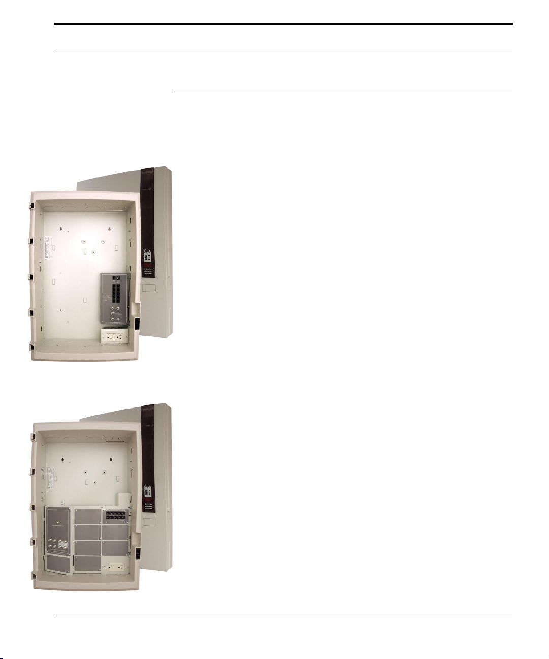
400 Series for CATV
400 Series for CATV
The 400 Series is designed for homes which are wired with UStec 2X2 tecWire
for up to 4 multimedia tecPort locations. Each model provides a passive coaxial cable distribution for up to 4 TV’s. The tecLAN400Basic models and higher
include a cable signal combiner with a built-in high pass filter to eliminate
potential interference with cable channels from in-home generated
VCR,DVD or camera channels. Up to 10 phone locations may be connected,
each with 4 phone line capacity. The optional holsters provide a hinged
mounting bracket for cable modems, DSL modems, and home server appliances.
Common to all systems is the UX-10x cabinet that houses all the wire and
tecCenter panel equipment. Each cabinet houses an electrical outlet in the
lower right hand corner to power UStec and third part peripherals.
Each system is enclosed in a integrated plastic cover and drywall trim kit.
Each cover can be locked with the addition of the cover locking kit, part
number UX-408.
Optional satellite connectivity can be added to these system. Contact your
dealer for more information.
tecReady 400
This system uses the UX-222 service module and is designed to distribute an
off-air or cable television signal and distribute it in up 4 different locations
in the home. It can accept up to four telephone lines and distribute them to
10 different locations in the home. Additionally it has a RJ31X line grabbing
interface for a security panel. This system can be upgraded to any of the following systems.
tecLAN 400 Basic
This system is designed to distribute an off-air or cable television signal up
to 4 different locations in the home. The CX-4X4U.1 module that distributes
the off-air or cable television signals also has 4 internal inputs. The internal
ports allows for in home generated television signals to be viewable any-
UStec Structured Wiring User Manual
23
Page 24
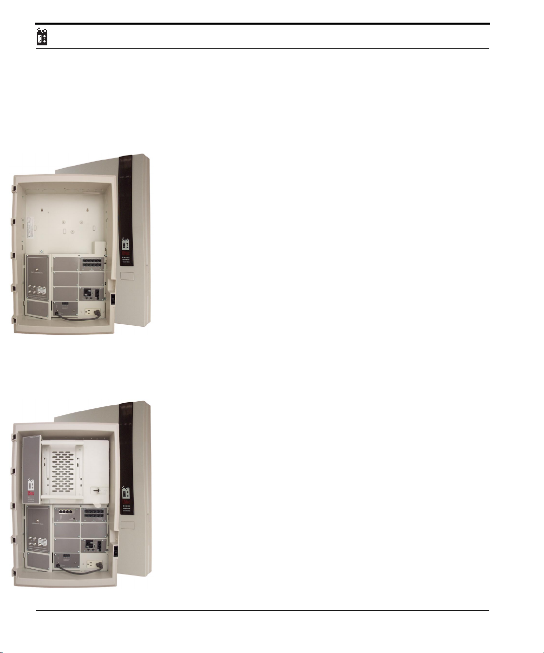
where in the home. Examples might be a DVD player that you would also like
to see in the bedroom.
The TP-DM10B telecom module will distribute up to 4 incoming telephone
lines out to 9 different locations in the home. This device can be upgraded to
any of the following 400 series systems.
tecLAN 400
This system is designed to distribute an off-air or cable television signal up to
4 different locations in the home. The CX-4X4U.1 module that distributes
the off-air or cable television signals also has 4 internal inputs. The module
has an integrated internals to take in home generated signals from an
optional RF modulator and pass them for distribution to all rooms in the
home. Examples might be a DVD player that you would also like to see in the
bedroom.
Up to 4 incoming telephone lines are plugged into the TP-IN4RS module.
This device will surge protect all 4 incoming telephone lines and distribute
them to 10 different locations via the TP-DM10R module. Additionally the
TP-IN4RS module provides security line grabbing interfaces (RJ31X) on telephone lines 1 and 2. This module also provides a conduit to Key System telephone Units (KSU). This system can be upgraded to the following systems.
24
iLAN 400
This system is designed to distribute an off-air or cable television signal up
to 4 different locations in the home. The CX-4X4U.1 module that distributes
the off-air or cable television signals also has 4 internal inputs. The module
has an integrated internals to take in home generated signals from an
optional RF modulator and pass them for distribution to all rooms in the
home. Examples might be a DVD player that you would also like to see in
the bedroom.
Up to 4 incoming telephone lines are plugged into the TP-IN4RS module.
This device will surge protect all 4 incoming telephone lines and distribute
them to 10 different locations via the TP-DM10R module. Additionally the
TP-IN4RS module provides security line grabbing interfaces (RJ31X) on telephone lines 1 and 2. This module also provides a conduit to Key System telephone Units (KSU).
UStec Structured Wiring Users Manual
Page 25

400 Series for CATV
A six port (1 is broadband connection, 1 is cascade to optional second unit)
10/100 Ethernet switch is included as well. It provides for the connection of
up to 4 different computers in addition to a broadband sharing device that is
mounted in the included gateway holster.
The flexible holster design is capable of handling a host of broadband devices
from cable modem routers, xDSL routers, even third party servers.
UStec Structured Wiring User Manual
25
Page 26

26
UStec Structured Wiring Users Manual
Page 27
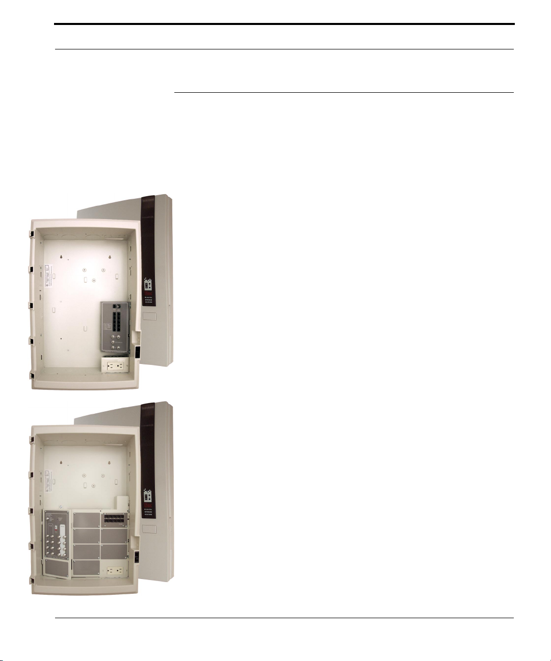
800 Series for CATV
800 Series for CATV
The 800 series for CATV is designed for homes which are wired with UStec
2X2 tecWire for up to 8 multimedia tecPort locations. The tecLAN800 Basic
models and higher include a digital CATV amplifier with a built-in high pass
filter to eliminate potential interference with cable channels from in-home
generated VCR,DVD or camera channels. Up to 10 phone locations may be
provided, each with 4 phone line capacity. The optional holsters provide a
hinged mounting bracket for cable modems, DSL modems and home server
appliances. (Holster standard on iLAN systems)
Common to all systems is the UX-10x cabinet that houses all the tecWire and
tecCenter panel equipment. Each cabinet houses an electrical outlet in the
lower right hand corner to power UStec and third part peripherals.
Each system is enclosed in a integrated plastic cover and drywall trim kit.
Each cover can be locked with the addition of the cover locking kit, part
number UX-408.
Optional satellite connectivity can be added to these system. For more
advanced satellite options look at the 800 series for satellite. Contact your
dealer for more information.
tecReady 800
This system uses the UX-222 service module and is designed to distribute an
off-air or cable television signal and distribute it in up 4 different locations
in the home. It can accept up to four telephone lines and distribute them to
10 different locations in the home. Additionally it has a RJ31X line grabbing
interface for a security panel. This system can be upgraded to any of the following systems.
tecLAN 800 Basic
This system is designed to distribute an off-air or cable television signal up
to 8 different locations in the home. The CX-AMP8 is a studio quality
amplifier built to the highest standards that cable companies require. Off air
antenna or cable television service enter the input on the CX-AMP8. The
amplifier then amplifies the signal enough to cover the splitting of the signal
UStec Structured Wiring User Manual
27
Page 28
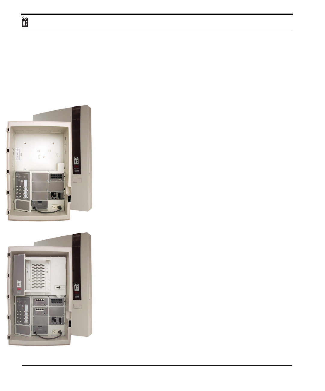
and sends it out to 8 different television locations via the TV out ports. Additionally there are 8 internal inputs for the input of in home generated signals.
The module has an integrated internals to take in home generated signals
from an optional RF modulator and pass them for distribution to all rooms
in the home. Examples might be a DVD player that you would also like to see
in the bedroom. The TP-DM10B telecom module will distribute up to 4
incoming telephone lines out to 9 different locations in the home. This
device can be upgraded to any of the following 800 series systems.
tecLAN 800
This system is The CX-AMP8 is a studio quality amplifier built to the highest
standards that cable companies require.The off air antenna or cable television service enter the input on the CX-AMP8. The amplifier then amplifies
the signal enough to cover the splitting of the signal and sends it out to 8
different television locations via the TV out ports. Additionally there are 8
internal inputs for the input of in home generated signals. The module has
an integrated internals to take in home generated signals from an optional
RF modulator and pass them for distribution to all rooms in the home.
Examples might be a DVD player that you would also like to see in the bedroom.
Up to 4 incoming telephone lines are plugged into the TP-IN4RS module.
This device will surge protect all 4 incoming telephone lines and distribute
them to 10 different locations via the TP-DM10R module. Additionally the
TP-IN4RS module provides security line grabbing interfaces (RJ31X) on telephone lines 1 and 2. This module also provides a conduit to Key System
telephone Units (KSU). This system can be upgraded to the following systems.
28
iLAN 800
This system is designed to distribute off-air or cable television signal up to 8
different locations in the home. The CX-AMP8 is a studio quality amplifier
built to the highest standards that cable companies require. The off air
antenna or cable television service enter the input on the CX-AMP8. The
amplifier then amplifies the signal enough to cover the splitting of the signal
and sends it out to 8 different television locations via the TV out ports. Additionally there are 8 internal inputs for the input of in home generated sig-
nals. The module has an integrated internals to take in home generated
UStec Structured Wiring Users Manual
Page 29
800 Series for CATV
signals from an optional RF modulator and pass them for distribution to all
rooms in the home. Examples might be a DVD player that you would also
like to see in the bedroom.
Up to 4 incoming telephone lines are plugged into the TP-IN4RS module.
This device will surge protect all 4 incoming telephone lines and distribute
them to 10 different locations via the TP-DM10R module. Additionally the
TP-IN4RS module provides security line grabbing interfaces (RJ31X) on telephone lines 1 and 2. This module also provides a conduit to Key System telephone Units (KSU).
Two 10/100 Ethernet switches are included as well for a total nine ports. It
provides for the connection of up to 8 different computers in addition to a
broadband sharing device that is mounted in the included gateway holster.
The flexible holster design is capable of handling a host of broadband devices
from cable modem routers, xDSL routers, even third party servers.
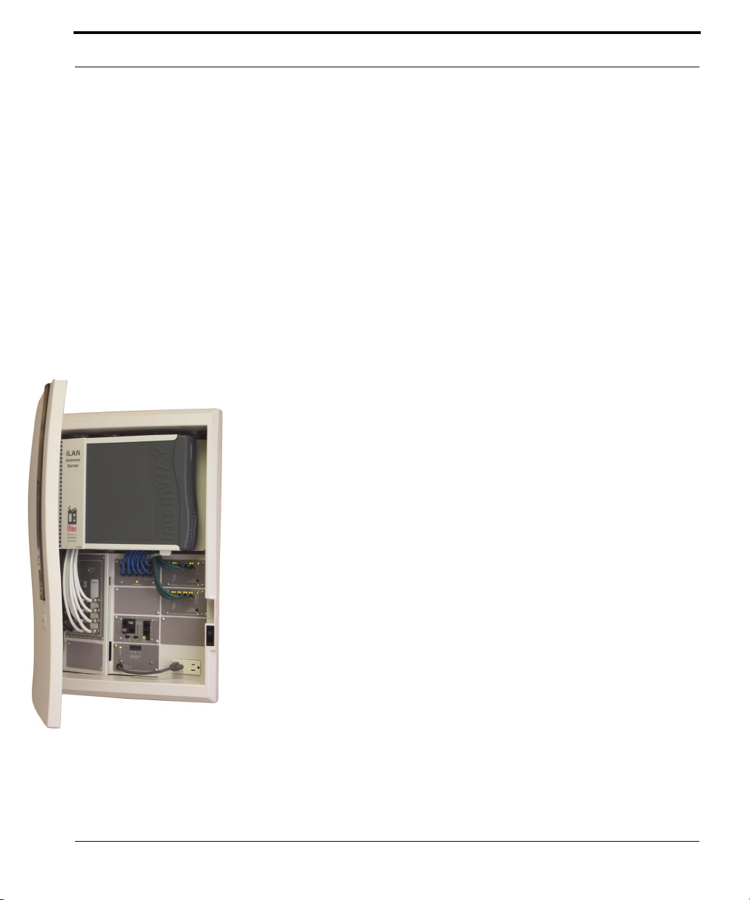
iLAN 800 – GS
This system is designed to distribute off-air or cable television signal up to 8
different locations in the home. The CX-AMP8 is a studio quality amplifier
built to the highest standards that cable companies require. The off air
antenna or cable television service enter the input on the CX-AMP8. The
amplifier then amplifies the signal enough to cover the splitting of the signal
and sends it out to 8 different television locations via the TV out ports. Additionally there are 8 internal inputs for the input of in home generated signals.
The module has an integrated internals to take in home generated signals
from an optional RF modulator and pass them for distribution to all rooms
in the home. Examples might be a DVD player that you would also like to see
in the bedroom.
Up to 4 incoming telephone lines are plugged into the TP-IN4RS module.
This device will surge protect all 4 incoming telephone lines and distribute
them to 10 different locations via the TP-DM10R module. Additionally the
TP-IN4RS module provides security line grabbing interfaces (RJ31X) on telephone lines 1 and 2. This module also provides a conduit to Key System telephone Units (KSU).
UStec Structured Wiring User Manual
29
Page 30

Also included is a state of the art residential gateway server called IntelliWAY.
This gateway device works to provide a central source for your broadband
connections, from Internet connection sharing, to firewall security, file sharing, or backup. The IntelliWAY is connected to your home network through
two TP-10/100BT Ethernet switches. Below is a more detailed list of features
of the gateway server.
Hardware Features
•Centralized, Removable Storage (80Gb Standard)
•1 Ethernet LAN (with crossover switch)
•1 Ethernet WAN (Built-in DSL, Cable Modem future option)
•1 PC Card Slot (pre-configured 802.11b wireless optional)
•2 2 PCI Slots (1 contains Ethernet LAN card)
•2 USB Sockets (Future Usage)
•1 Printer Port
Software Features
•BaseLine Operating System (Linux based)
•Web Based UI
•Routing & Bridging
•File Sharing and Backup Support
•Service Modules
•Security
•NAT Firewall Protection
•Intrusion Management
•Anti-Virus
•Network Management
•Content Filtering/URL Blocking
•Bandwidth Control
•Remote Global Management
•Communications
•VPN
•VoIP
•Surveillance
•Remote Monitoring
•Reporting
•Entertainment
•P2P File Sharing
30
UStec Structured Wiring Users Manual
Page 31

800 Series for CATV
•VOD
•Gaming
•Energy Management
•HVAC Automation
•Appliance Controls
UStec Structured Wiring User Manual
31
Page 32

32
UStec Structured Wiring Users Manual
Page 33
800 Series for Satellite TV & Antenna
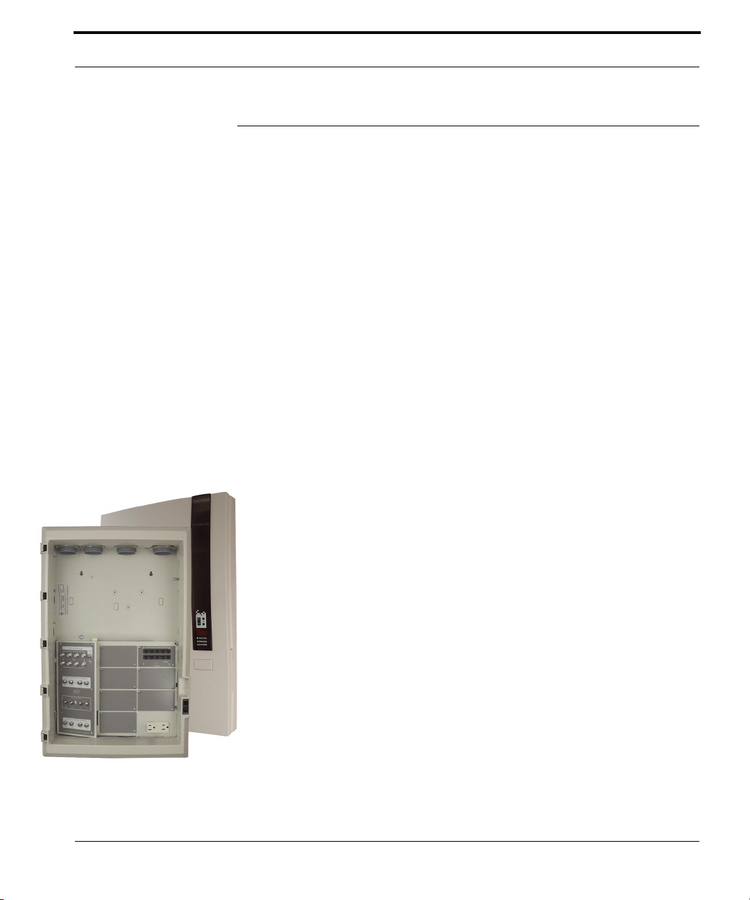
800 Series for Satellite TV & Antenna
The HDTV Satellite TV model lines deliver full high definition satellite signals
throughout the home to satellite receivers at up to 8 TV set locations. Satellite
signals are distributed though the “Internal” coax tecPort wall connections
along with cable or off-air broadcast TV through the “TV” coax tecPort connections. The system does not restrict modulated inputs at any tecPort location. The 800 Satellite Series offers only passive broadcast TV signal
distribution. This configuration is not recommended for CATV applications
since it requires a minimum of 15 dB signal input levels and lacks the guard
band high-pass filter that the CX-AMP series amplifiers provide.
Common to all systems is the UX-10x cabinet that houses all the wire and tecCenter equipment. Each cabinet houses an electrical outlet in the lower right
hand corner to power UStec and third part peripherals.
Each system is enclosed in a integrated plastic cover and drywall trim kit.
Each cover can be locked with the addition of the cover locking kit, part number UX-408.
tecSat 800 Basic
This system is capable of distributing satellite and pre-amplified off air
antenna signals to 8 different locations throughout the home. The CXHDA58 module is an integrated satellite/off-air distribution system. The satellite multiswitch will handle 2 or 4 LNB (HDTV) input cables from the satellite dish(s) for independent distribution to 8 locations. The multiswitch
has an integrated internals amplifier to take in home generated signals from
an optional RF modulator and pass them for distribution to all rooms in the
home. This occurs by combining the in home generated signals with the off
air antenna via the TV out ports.
The TP-DM10B telecom module will distribute up to 4 incoming telephone
lines out to 9 different locations in the home. This system can be upgraded
to the following systems.
UStec Structured Wiring User Manual
33
Page 34
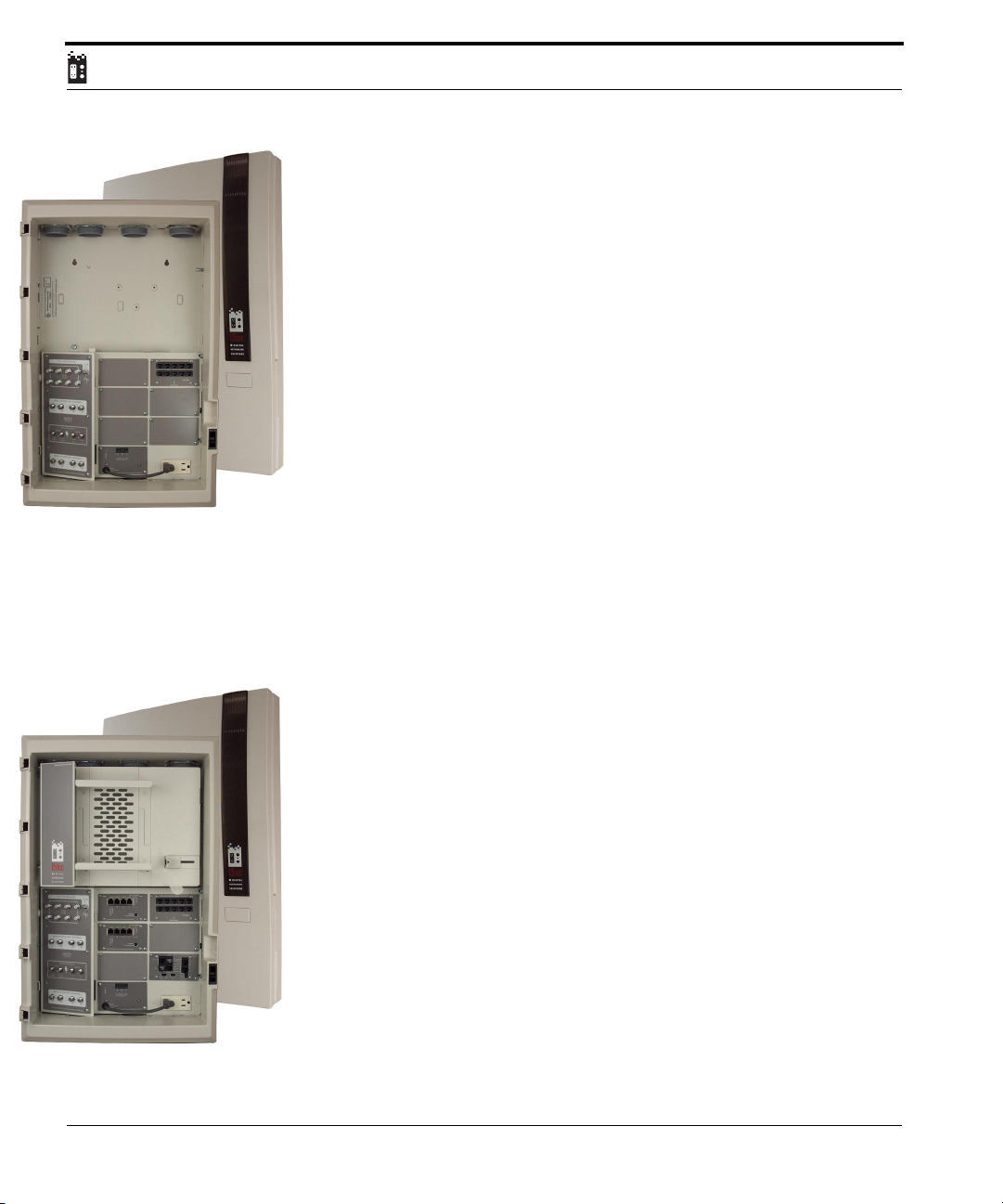
tecSAT 800
This system is capable of distributing satellite and off air antenna to 8 different locations throughout the home. The CX-HDA58 module is an integrated
satellite/off-air distribution system. The satellite multiswitch will handle 2
or 4 LNB (HDTV) input cables from the satellite dish(s) for independent
distribution to 8 locations. The multiswitch has an integrated internals
amplifier to take in home generated signals from an optional RF modulator
and pass them for distribution to all rooms in the home. This occurs by
combining the in home generated signals with the off air antenna via the TV
out ports.
Up to 4 incoming telephone lines are plugged into the TP-IN4RS module.
This device will surge protect all 4 incoming telephone lines and distribute
them to 10 different locations via the TP-DM10R module. Additionally the
TP-IN4RS module provides security line grabbing interfaces (RJ31X) on telephone lines 1 and 2. This module also provides a conduit to Key System telephone Units (KSU). This unit can be upgraded to the iSAT 800.
iSAT 800
This system is capable of distributing satellite and off air antenna to 8 different locations throughout the home. The CX-HDA58 module is an integrated
satellite/off-air distribution system. The satellite multiswitch will handle 2 or
4 LNB (HDTV) input cables from the satellite dish(s) for independent distribution to 8 locations. The multiswitch has an integrated internals amplifier
to take in home generated signals from an optional RF modulator and pass
them for distribution to all rooms in the home. This occurs by combining
the in home generated signals with the off air antenna via the TV out ports.
34
Up to 4 incoming telephone lines are plugged into the TP-IN4RS module.
This device will surge protect all 4 incoming telephone lines and distribute
them to 10 different locations via the TP-DM10R module. Additionally the
TP-IN4RS module provides security line grabbing interfaces (RJ31X) on telephone lines 1 and 2. This module also provides a conduit to Key System telephone Units (KSU)
Two 10/100 Ethernet switches are included as well for a total nine ports. It
provides for the connection of up to 8 different computers in addition to a
broadband sharing device that is mounted in the included gateway holster.
UStec Structured Wiring Users Manual
Page 35

800 Series for Satellite TV & Antenna
The flexible holster design is capable of handling a host of broadband devices
from cable modem routers, xDSL routers, even third party servers.
UStec Structured Wiring User Manual
35
Page 36

36
UStec Structured Wiring Users Manual
Page 37
850 Series for Satellite TV & CATV
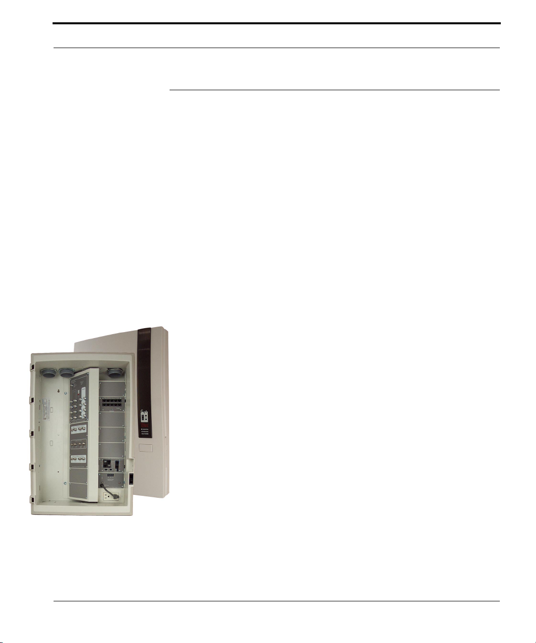
850 Series for Satellite TV & CATV
The 850 series provide complete choice of HDTV satellite, CATV or off-air
broadcast TV at 8 multimedia 2x2 tecPort locations. Satellite signals are distributed though the “Internal” coax tecPort wall connections along with
Cable or Off-air Broadcast TV through the “TV” coax tecPort connections.
The iSAT850 Series includes an expansion cabinet for the computer networking components.
Common to all systems is the UX-10x cabinet that houses all the wire and tecCenter equipment. Each cabinet houses an electrical outlet in the lower right
hand corner to power UStec and third part peripherals.
Each system is enclosed in a integrated plastic cover and drywall trim kit.
Each cover can be locked with the addition of the cover locking kit, part number UX-408.
tecSat 850
This system is capable of distributing satellite and either cable television or
off air antenna signals to 8 different locations throughout the home. The
CX-DSS58 is a 5 in and 8 out high definition capable satellite multiswitch.
The satellite multiswitch will handle 2 or 4 LNB (HDTV) input cables from
the satellite dish(s) for independent distribution to 8 locations. The multiswitch has an integrated internals amplifier to take in home generated signals from an optional RF modulator and pass them to the CX-AMP8 for
distribution to all rooms in the home. This occurs by combining the in
home generated signals with the cable television signals on the CX-AMP8
via the TV out ports.
The CX-AMP8 is a studio quality amplifier built to the highest standards
that cable companies require. The off air antenna or cable television service
enter the input on the CX-AMP8. The amplifier then amplifies the signal
enough to cover the splitting of the signal and sends it out to 8 different
television locations via the TV out ports.
Up to 4 incoming telephone lines are plugged into the TP-IN4RS module.
This device will surge protect all 4 incoming telephone lines and distribute
them to 10 different locations via the TP-DM10R module. Additionally the
TP-IN4RS module provides security line grabbing interfaces (RJ31X) on tele-
UStec Structured Wiring User Manual
37
Page 38
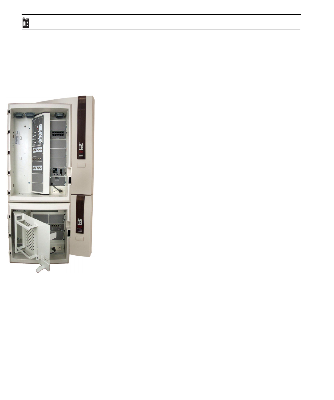
phone lines 1 and 2. This module also provides a conduit to Key System telephone Units (KSU). This system can be upgraded to the iSAT 850 system. An
additional mounting cabinet is necessary.
iSAT 850
This is a dual cabinet system. RF and telecommunications are in the large
cabinet (UX-10x) and data communications are in the small cabinet (UX75x)
This system is capable of distributing satellite to 8 different locations
throughout the home. The CX-DSS58 is a 5 in and 8 out high definition
capable satellite multiswitch. The satellite multiswitch will handle 2 or 4
LNB (HDTV) input cables from the satellite dish(s) for independent distribution to 8 locations. The multiswitch has an integrated internals amplifier
to take in home generated signals from an optional RF modulator and pass
them to the CX-AMP8 for distribution to all rooms in the home. This occurs
by combining the in home generated signals with the cable television signals
on the CX-AMP8 via the TV out ports.
The CX-AMP8 is a studio quality amplifier built to the highest standards that
cable companies require. The off air antenna or cable television service enter
the input on the CX-AMP8. The amplifier then amplifies the signal enough
to cover the splitting of the signal and sends it out to 8 different television
locations via the TV out ports.
38
Up to 4 incoming telephone lines are plugged into the TP-IN4RS module.
This device will surge protect all 4 incoming telephone lines and distribute
them to 10 different locations via the TP-DM10R module. Additionally the
TP-IN4RS module provides security line grabbing interfaces (RJ31X) on telephone lines 1 and 2. This module also provides a conduit to Key System telephone Units (KSU)
In the small cabinet is an iLAN 8B which consists of two 10/100 Ethernet
switches for a total nine Ethernet ports. It provides for the connection of up
to 8 different computers in addition to a broadband sharing device that can
be mounted in the included gateway holster.
The flexible holster design is capable of handling a host of broadband devices
from cable modem routers, xDSL routers, even third party servers.
UStec Structured Wiring Users Manual
Page 39

850 Series for Satellite TV & CATV
UStec Structured Wiring User Manual
39
Page 40

40
UStec Structured Wiring Users Manual
Page 41
1600 Series For CATV
1600 Series For CATV
The 1600 series is designed for homes wired with UStec 2X2 tecWire for up to
16 multimedia tecPort locations. The tecLAN1600Basic models and higher
include a digital CATV amplifier with a built-in high pass filter to eliminate
potential interference with cable channels from in-home generated VCR,DVD
or camera channels. Up to 20 phone locations may be provided, each with 4
phoneline capacity. The optional holsters provide a hinged mounting bracket
for cable modems, DSL modems and home server appliances. (Holster stan-
dard on iLAN systems)
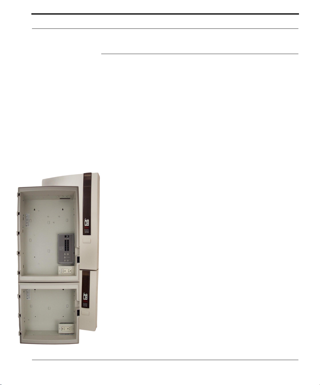
Common to all systems is the large UX-10x cabinet and the smaller UX-75x
cabinet. The larger cabinet houses the RF and telecommunications modules,
while the smaller cabinet handles the data communications. Each cabinet
houses an electrical outlet in the lower right hand corner to power UStec and
third part peripherals.
Each system is enclosed in a integrated plastic cover and drywall trim kit.
Each cover can be locked with the addition of the cover locking kit, part
number UX-408.
For satellite connectivity a CX-DSS58 module can be added for high-definition capable satellite in 8 locations. Contact your dealer for more information.
tecReady 1600
This system uses the UX-222 service module and is designed to distribute an
off-air or cable television signal and distribute it in up 16 different locations
in the home. It can accept up to four telephone lines and distribute them to
10 different locations in the home. Additionally it has a RJ31X line grabbing
interface for a security panel. This system can be upgraded to any of the following systems. This system can be upgraded to any (CATV/SAT or CATV
only) series 1600 system.
UStec Structured Wiring User Manual
41
Page 42
tecLAN 1600 Basic
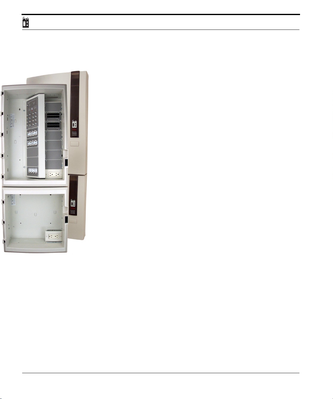
This system is designed to distribute the off-air or cable television signal to 16
different locations in the home. The CX-AMP16 is a studio quality amplifier
built to the highest standards that cable companies require.
The off-air antenna or cable television service enter the input on the CXAMP16. The amplifier then amplifies the signal enough to cover the splitting
of the signal and sends it out to 16 different television locations via the TV
out ports. The 16 outputs are tiered into two banks of 8. One set of banks has
a higher output for the longer runs typical in a 16 port configuration.
Additionally there are 16 internal inputs for the input of in home generated
signals. The system has two 8 way internals (16 total) to take in home generated signals from an optional RF modulator and pass them for distribution to
all rooms in the home. Examples might be a DVD player that you would also
like to see in the bedroom.
The two TP-DM10R telecom modules will distribute up to 4 incoming telephone lines out to 19 different locations in the home. This device can be
upgraded to any of the 1600 series systems.
42
UStec Structured Wiring Users Manual
Page 43
1600 Series For CATV
tecLAN 1600
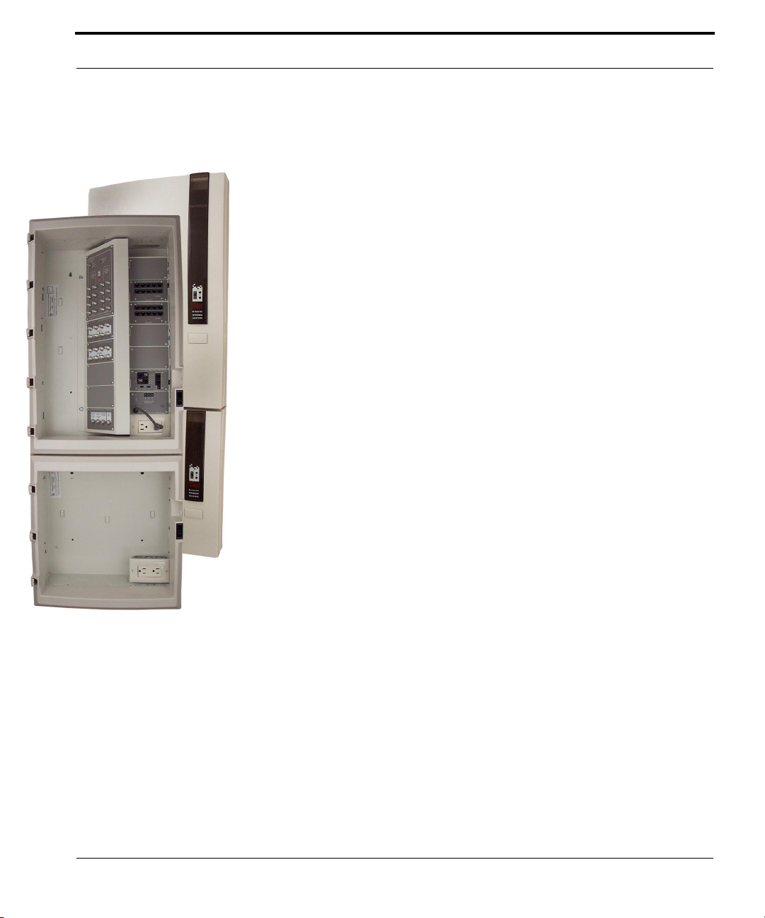
This system is designed to distribute the off-air or cable television signal to 16
different locations in the home. The CX-AMP16 is a studio quality amplifier
built to the highest standards that cable companies require.
The off-air antenna or cable television service enter the input on the CXAMP16. The amplifier then amplifies the signal enough to cover the splitting
of the signal and sends it out to 16 different television locations via the TV
out ports. The 16 outputs are tiered into two banks of 8. One set of banks has
a higher output for the longer runs typical in a 16 port configuration.
Additionally there are 16 internal inputs for the input of in home generated
signals. The system has two 8 way internals (16 total) to take in home generated signals from an optional RF modulator and pass them for distribution to
all rooms in the home. Examples might be a DVD player that you would also
like to see in the bedroom.
Up to 4 incoming telephone lines are plugged into the TP-IN4RS module.
This device will surge protect all 4 incoming telephone lines and distribute
them to 20 different locations via two TP-DM10R modules.
Additionally the TP-IN4RS module provides security line grabbing interfaces
(RJ31X) on telephone lines 1 and 2. This module also provides a conduit to
Key System telephone Units (KSU). This system can be upgraded to any 1600
series system.
UStec Structured Wiring User Manual
43
Page 44
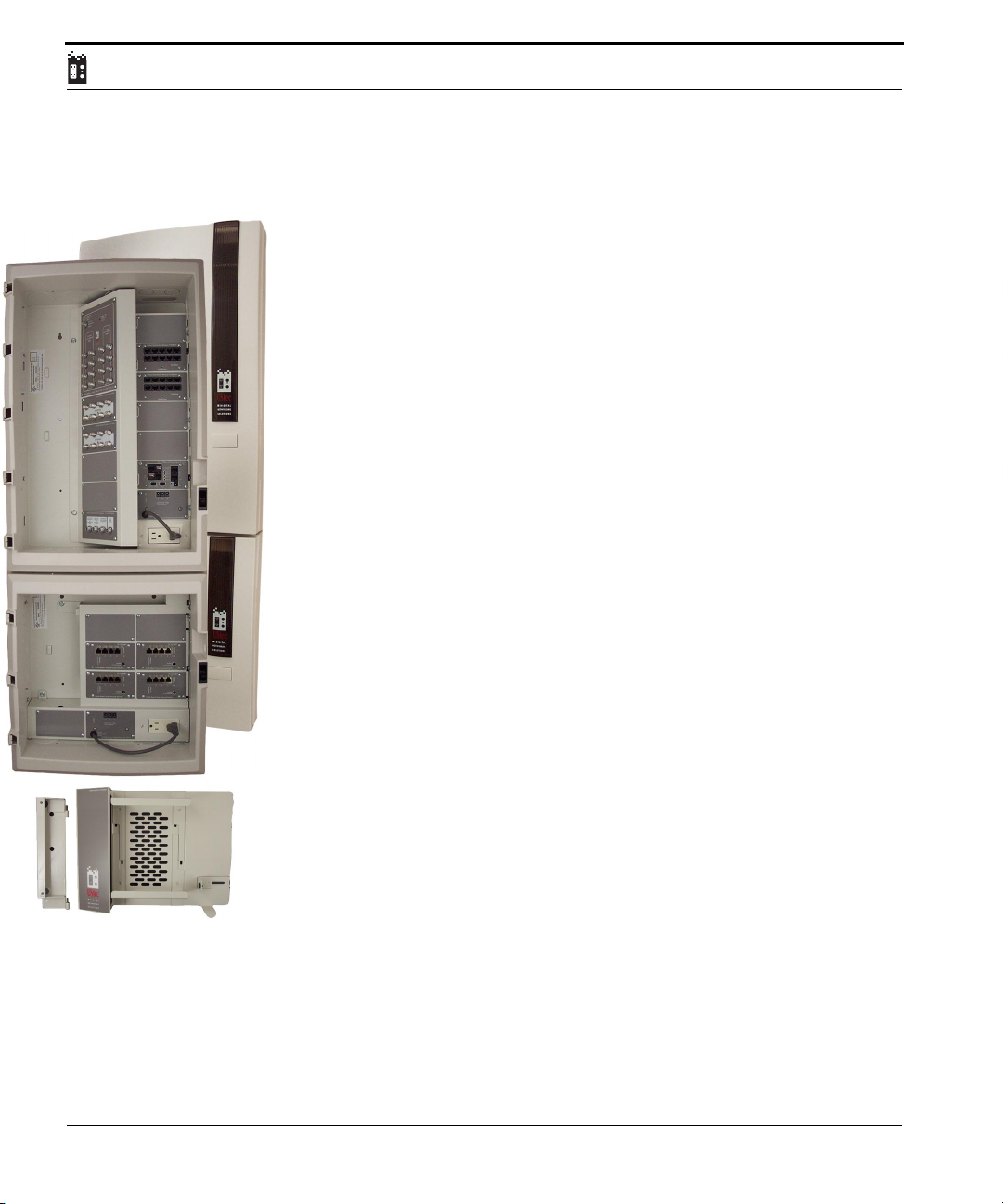
iLAN 1600
This system is designed to distribute the off-air or cable television signal to 16
different locations in the home. The CX-AMP16 is a studio quality amplifier
built to the highest standards that cable companies require.
The off-air antenna or cable television service enter the input on the CXAMP16. The amplifier then amplifies the signal enough to cover the splitting
of the signal and sends it out to 16 different television locations via the TV
out ports. The 16 outputs are tiered into two banks of 8. One set of banks has
a higher output for the longer runs typical in a 16 port configuration.
Additionally there are 16 internal inputs for the input of in home generated
signals. The module has an integrated internals to take in home generated
signals from an optional RF modulator and pass them for distribution to all
rooms in the home. Examples might be a DVD player that you would also
like to see in the bedroom.
Up to 4 incoming telephone lines are plugged into the TP-IN4RS module.
This device will surge protect all 4 incoming telephone lines and distribute
them to 20 different locations via two TP-DM10R modules. Additionally the
TP-IN4RS module provides security line grabbing interfaces (RJ31X) on telephone lines 1 and 2. This module also provides a conduit to Key System telephone Units (KSU).
44
In the small cabinet (UX-75x) is an iLAN 16B which consists of four 10/100
Ethernet switches for a total sixteen Ethernet ports. It provides for the connection of up to 16 different computers in addition to a broadband sharing
device that is mounted in the included gateway holster.
The flexible holster design is capable of handling a host of broadband devices
from cable modem routers, xDSL routers, even third party servers.
UStec Structured Wiring Users Manual
Page 45

1600 Series For Satellite / CATV or Antenna
1600 Series For Satellite / CATV or Antenna
The 1600 satellite series provides complete choice of HDTV satellite, and
CATV or off-air broadcast TV in one system. Up to 8 high definition and 16
cable or off-air ports can be accommodated with these systems. The iSAT1600
Series includes an expansion cabinet for the computer networking components.
Common to all systems is the large UX-10x cabinet and the smaller UX-751
cabinet. The larger cabinet houses the RF and telecommunications modules,
while the smaller cabinet handles the data communications. Each cabinet
houses an electrical outlet in the lower right hand corner to power UStec and
third part peripherals.
Each system is enclosed in a integrated plastic cover and drywall trim kit.
Each cover can be locked with the addition of the cover locking kit, part number UX-408.
UStec Structured Wiring User Manual
45
Page 46
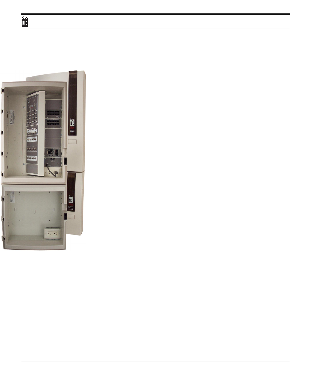
tecSAT 1600
This system is designed to distribute the off-air or cable television signal to 16
different locations in the home and satellite to 8 locations.
The CX-DSS58 is a 5 in and 8 out high definition capable satellite multiswitch. The satellite multiswitch will handle 2 or 4 LNB (HDTV) input cables
from the satellite dish(s) for independent distribution to 8 locations. The
multiswitch has an integrated internals amplifier to take in home generated
signals from an optional RF modulator and pass them to the CX-AMP16 for
distribution to all rooms in the home. This occurs by combining the in home
generated signals with the cable television signals on the CX-AMP16 via the
TV out ports. Examples might be a DVD player that you would also like to see
in the bedroom.
The CX-AMP16 is a studio quality amplifier built to the highest standards
that cable companies require. The off air antenna or cable television service
enter the input on the CX-AMP16. The amplifier then amplifies the signal
enough to cover the splitting of the signal and sends it out to 16 different
television locations via the TV out ports. The 16 outputs are tiered into two
banks of 8. One set of banks has a higher output for the longer runs typical in
a 16 port configuration.
Additionally there are 16 internal inputs for the input of in home generated
signals.The module has a separate 8 way internals module (in addition to 8
provided via satellite multiswitch) to take in home generated signals from an
optional RF modulator and pass them for distribution to all rooms in the
home. Examples might be a DVD player that you would also like to see in the
bedroom.
46
Up to 4 incoming telephone lines are plugged into the TP-IN4RS module.
This device will surge protect all 4 incoming telephone lines and distribute
them to 20 different locations via two TP-DM10R modules. Additionally the
TP-IN4RS module provides security line grabbing interfaces (RJ31X) on telephone lines 1 and 2. This module also provides a conduit to Key System telephone Units (KSU). This system can be upgraded to any 1600 series system.
UStec Structured Wiring Users Manual
Page 47
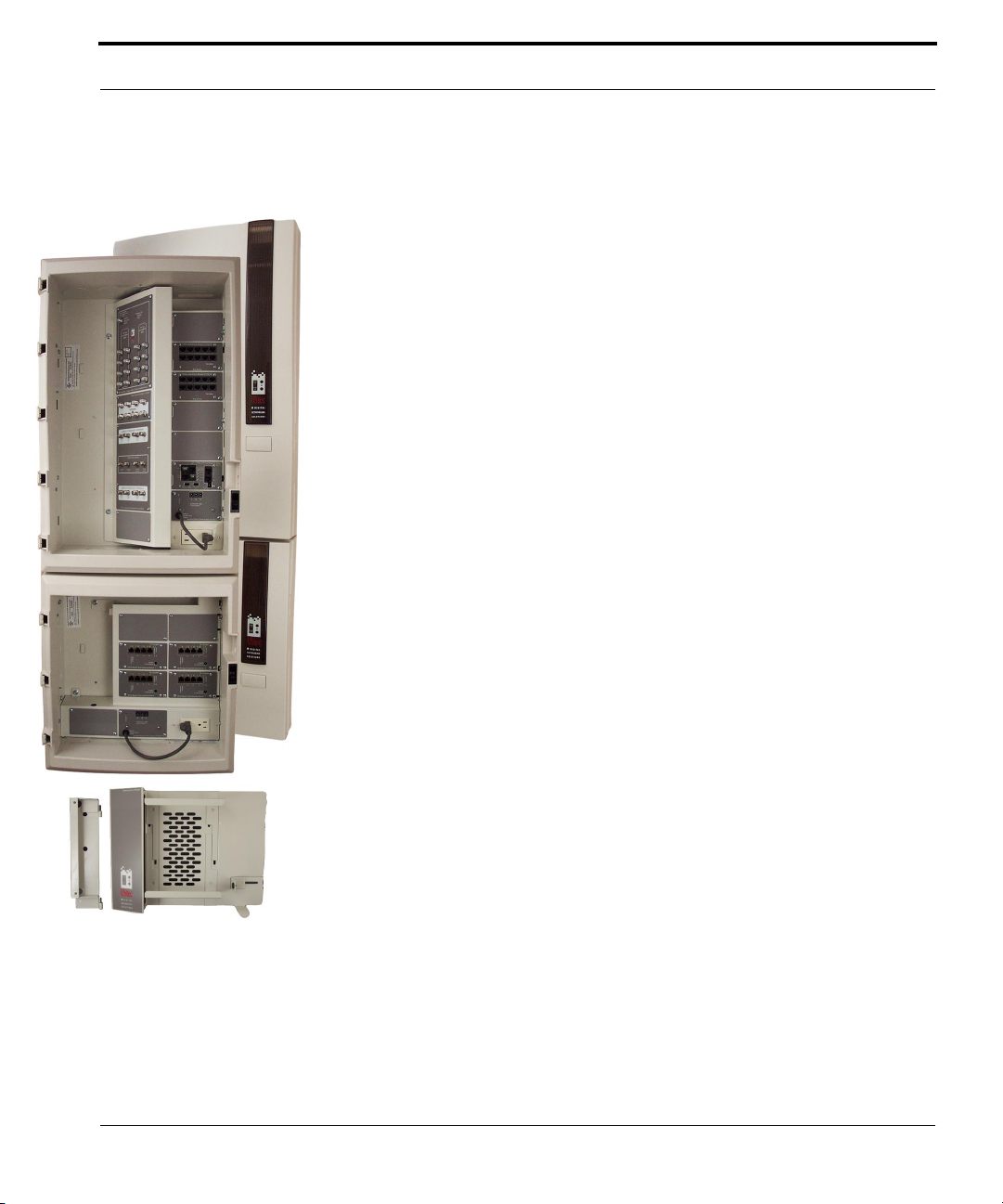
1600 Series For Satellite / CATV or Antenna
iSAT 1600
This system is designed to distribute the off-air or cable television signal to 16
different locations in the home and satellite to 8 locations.
The CX-DSS58 is a 5 in and 8 out high definition capable satellite multiswitch. The satellite multiswitch will handle 2 or 4 LNB (HDTV) input cables
from the satellite dish(s) for independent distribution to 8 locations. The
multiswitch has an integrated internals amplifier to take in home generated
signals from an optional RF modulator and pass them to the CX-AMP16 for
distribution to all rooms in the home. This occurs by combining the in home
generated signals with the cable television signals on the CX-AMP16 via the
TV out ports. Examples might be a DVD player that you would also like to see
in the bedroom.
The CX-AMP16 is a studio quality amplifier built to the highest standards
that cable companies require. The off air antenna or cable television service
enter the input on the CX-AMP16. The amplifier then amplifies the signal
enough to cover the splitting of the signal and sends it out to 16 different
television locations via the TV out ports. The 16 outputs are tiered into two
banks of 8. One set of banks has a higher output for the longer runs typical in
a 16 port configuration.
Additionally there are 16 internal inputs for the input of in home generated
signals.The module has a separate 8 way internals module (in addition to 8
provided via satellite multiswitch) to take in home generated signals from an
optional RF modulator and pass them for distribution to all rooms in the
home. Examples might be a DVD player that you would also like to see in the
bedroom.
In the small cabinet is an iLAN 16B which consists of four 10/100 Ethernet
switches for a total sixteen Ethernet ports. It provides for the connection of up
to 16 different computers in addition to a broadband sharing device that is
mounted in the included gateway holster.
The flexible holster design is capable of handling a host of broadband devices
from cable modem routers, xDSL routers, even third party servers.
This system can be upgraded to any 1600 series system.
UStec Structured Wiring User Manual
47
Page 48

48
UStec Structured Wiring Users Manual
Page 49
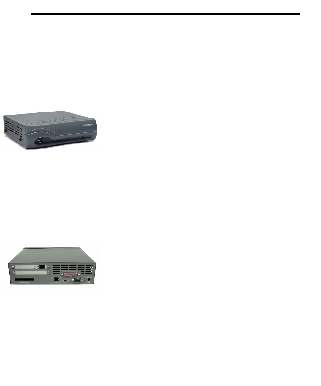
IntelliWAY Gateway Server
IntelliWAY Gateway Server
The Intelliway is a broadband Internet information appliance.
Here is a list of features.
•Router – provides advanced routing features. This makes it simple to set
up a home network. If your computer’s network card is configured for
DHCP which is the default on most modern operating systems, all you
need to do is just plug it in.
•Firewall – Protect your in home network. A router by default provides
protection by blocking access to the inside network. The advanced firewall
feature allows for more exacting protection in the form of statefull packet
inspection
•File Server – Serve up files for the family, store family photo’s, movies,
MP3 files, you name it. There are provisions for both public folders, anyone in your home can access and private folders which only your machine
can access. You can also use your IntelliWAY to back up your entire network.
•Wireless Access Point – An optional 802.11b wireless card is available
so that you can access your internal network both wired and wireless via
its built in bridging feature. The IntelliWAY comes ready with 128 WEP
encryption to keep your private items private.
•Content Filtering and URL Blocking- Block what family members can
view by setting up rules and completely blocking access to the sites you
choose.
•Bandwidth Control Controls the amount of bandwidth available to
each connected device.
•VPN Support – Virtual private networking allows for a secure connec-
tion between your computer and another network somewhere on the
Internet. Imperative for telecommuters.
•Security and Surveillance – Monitor your connections or set an IP
based camera up so that you can view it from anywhere in the world. No
more worrying when you go out of town.
•Health Monitoring – Monitor the status of your connections and
IntelliWAY server.
•*Energy Management – Future applications will allow for control of
HVAC components in your home
•*Audio and Video on Demand – Future IP based services will allow
you to rent movies on demand over the Internet. The IntelliWAY is ready
UStec Structured Wiring User Manual
49
Page 50

for such technologies. You can also save you’re audio visual files today for
distribution throughout your home.
* Some services are scheduled for future software releases. Some services
may require additional equipment.
The IntelliWAY is completely upgradeable for the future. It will tell you if
there are enhancements available to your system and allow you to upgrade it.
This appliance has been designed from the ground up to be ready for future
IP based technologies
50
UStec Structured Wiring Users Manual
Page 51

Cable Modem Hookup
Cable Modem Hookup
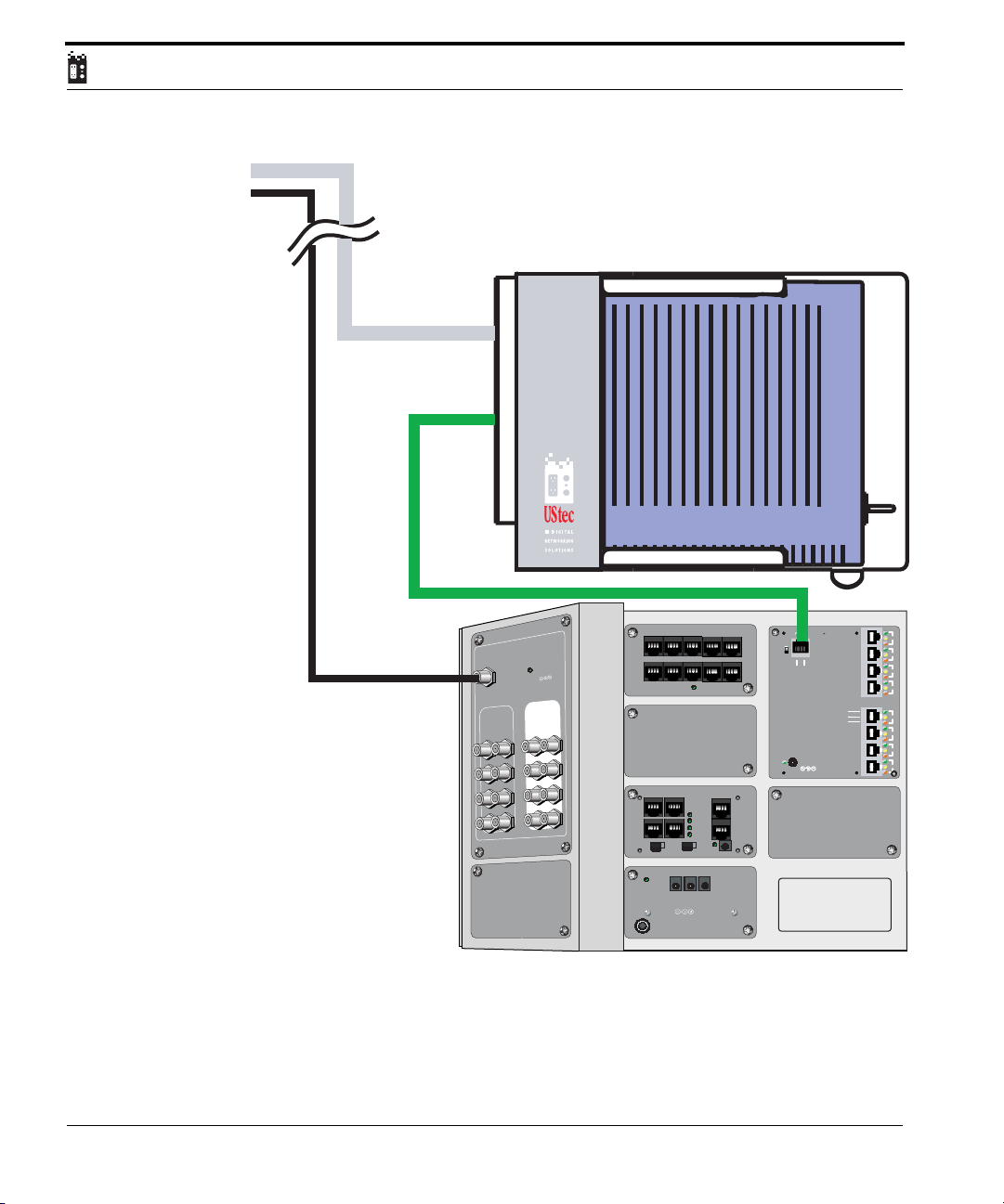
Most cable companies are now offering cable modem service which is a high
speed Internet service for the home. Most cable companies utilize the DOCSIS cable specifications for their networks and this section describes its connection.
The service is two way meaning that signals travel in two directions.
The downstream signal is the signal that originates at the cable company headend and comes to the home. This signal occupies a standard NTSC channel
(6 MHz) and is assigned by the cable company.
The upstream signal are signals originating from your home that go back to
the cable company headend.
Example:
You want to browse to the UStec website. You open your web browser and
type in http://www.ustecnet.com. This is an upstream request back to the headend. The cable company then sends your web browser via the downstream
connection the UStec web page.
UStec Structured Wiring User Manual
51
Page 52
Cable Modem feed
from NID
Ethernet CAT5 cable
52
Recommended
Input Signal Level
Incoming Cable Feed from NID
0 - 10 dB/mV
Power On
CATV/
12VDC
Antenna
Input
InternalInternalInternalInternal
TV Out
RF Amplifier - Surge - Return Path CX-AMP8.1
UStec Structured Wiring Users Manual
TPBus RJ45 Distribution Module TP-DM10R
TELCO Bus Active
TPBus Primary UTP Input Panel TP-IN4RS
X
1
3
J
R
2
e
in
L
IN
O
C
L
E
T
3
J
R
e
in
L
X
1
1
TELCO
E
C
B
u
s
T
P
0
/T
P
1
3
O
C
/ C
4
O
A
POWER
OUTPUTS A B C
12VDC / 250mA
INPUT
120VAC / 60Hz
tecGate Server Power Supply UX-DC6.2
C
C
C
C
F
O
F
N
O
T
E
S
T
B
WAN
Link
Activity
POWER
12V DC / 300mA
Link / Activity
Full Duplex
LAN Ports 1 - 4
2
3
4
100Mb
5
LAN Ports 5 - 8
6
7
8
II
X
T568A
IN
1
O
2
O
3
O
OUT
4
O
R
E
W
O
P
A
m
0
5
/ 2
C
D
V
2
1
REV B
A
T
T 5 DA
CA
UStec Internet
Router / Firewall TP-IPR8
Configuration interface http://192.168.1.1
1
C
Page 53

DSL hookup
DSL hookup
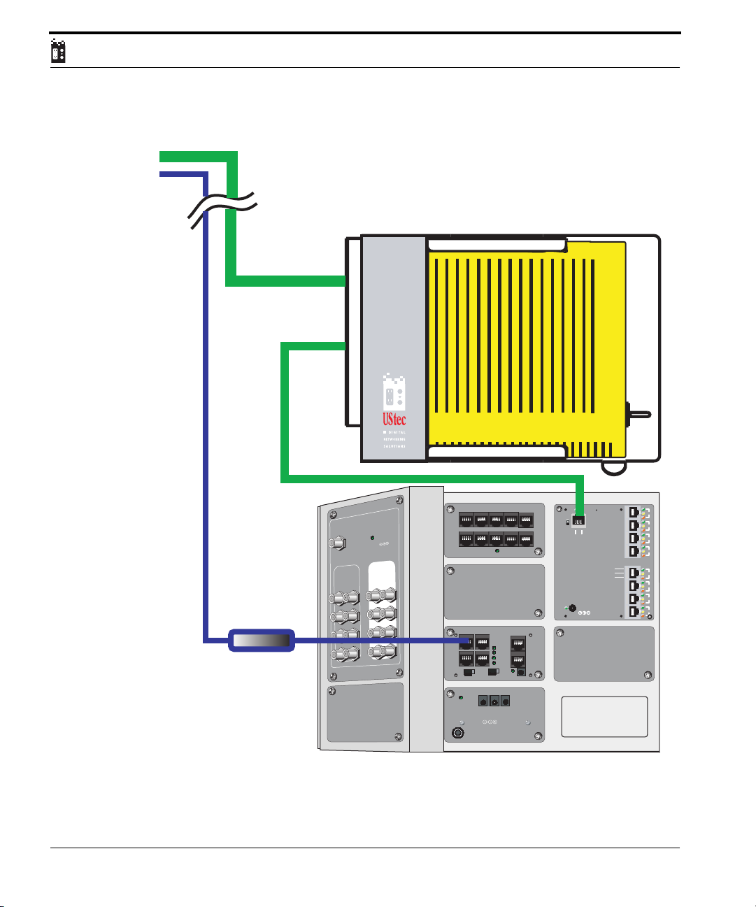
Most telecommunication companies, large Internet Service Providers (ISPs)
and some satellite companies are offering Digital Subscriber Line services.
DSL is a high speed Internet service that is typically piggybacked on top of
your existing telephone line. This can be piggy backed because the voice line
is at a lower frequency than the DSL.
The one drawback to this piggybacking DSL is that there is some residual
noise on the voice line when in use. Your service provider may have provided
DSL filters for your telephones. The logic behind this is that a filter is used at
every telephone. Below is a much simpler method of connecting a DSL
through your UStec system with only one filter.
UStec Structured Wiring User Manual
53
Page 54
InternalInternal
DSL feed
from NID
Ethernet CAT5 cable
54
d
mende
Recom
Level
Input Signal
V
Incoming unfiltered telecom feed from NID
0 - 10 dB/m
TV Out
CATV/
Antenna
Input
Power On
InternalInternal
12VDC
DSL filter
CX-AMP8.1
eturn Path
RF Amplifier - Surge - R
UStec Structured Wiring Users Manual
TPBus RJ45 Distribution Module TP-DM10R
TELCO Bus Active
TPBus Primary UTP Input Panel TP-IN4RS
X
1
3
J
R
2
e
in
L
IN
O
C
L
E
T
1
3
J
R
1
e
in
L
X
T
E
L
C
O
3
O
C
/ C
4
O
POWER
INPUT
120VAC / 60Hz
C
C
C
C
E
C
B
u
s
F
O
F
N
O
T
P
0
/T
P
1
T
E
S
T
A
B
OUTPUTS A B C
12VDC / 250mA
tecGate Server Power Supply
1
Link
Activity
POWER
12V DC / 300mA
LAN Ports 1 - 4
100Mb
LAN Ports 5 - 8
2
3
4
5
6
7
8
WAN
Link / Activity
Full Duplex
II
X
T568A
IN
1
O
2
O
3
O
OUT
4
O
R
E
W
O
P
A
m
0
5
/ 2
C
D
V
2
1
REV B
ATA
5 D
T
CA
UStec Internet
Router / Firewall TP-IPR8
Configuration interface http://192.168.1.1
C
UX-DC6.2
Page 55

Satellite Television Hookup
Satellite Television Hookup
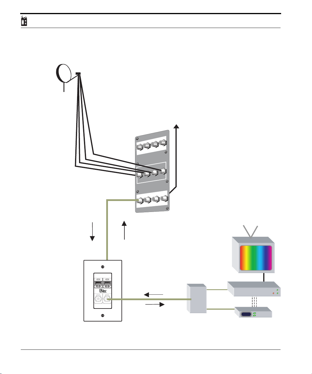
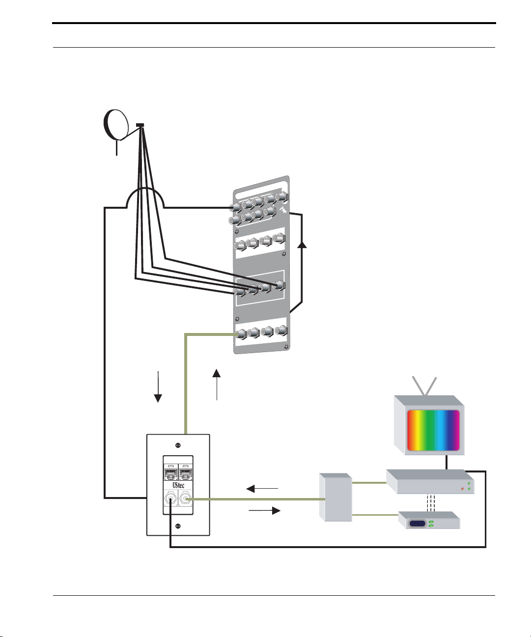
UStec provides a number of satellite options for your viewing pleasure. By far
the easiest systems to utilize satellite are our CX-HDA58 and CX-DSS58. Both
units are a 4 satellite input to 8 receiver output systems. This means that up to
8 receivers can be watching separate channels at the same time.
Please also note that although these have 4 LNB feeds in, it will work just as
well with satellite systems that have not upgraded to the second satellite location (2 LNB). High definition programming, as well as other ethnic and local
programming is available from the second satellite (LNB 3 and 4).
The CX-HDA58 and CX-DSS58 are designed to use the internal cables bidirectionally; by distributing satellite signals out to eight rooms while maintaining the ability to send modulated signals back on the same coax. Modulated signals that return to the multiswitch are amplified to ensure good
modulator signal strength, then routed to the amplifier.
Connections are simple. The following diagram show the connection points.
UStec Structured Wiring User Manual
55
Page 56
Satellite Antenna
CXDSS58 connection diagram
CX-DSS58 is a 4 satellite input and 8 output multiswitch
for DirecTV® Plus systems and compatible devices. The
switch utilizes standard 13V/18V switching on LNB inputs
1 and 2 and 13V 22khz/ 18V 22khz switching on ports
3 and 4. The switch is designed to be used with the
internal coax and has the ability to pass modulated feeds
from the room location for distribution throughout the
home on the same internal coaxial cable.
LNB
Feeds 1-4
Satellite Signal From CX-DSS58 to room location
Modulated Signals in room return to the
Data
Phone
TV
Internal
CX-DSS58 for whole house distribution
Internals
Internals
1 2 3 4
1 2 3 4
Satellite InputsSatellite Inputs
Satellite Inputs
z
h
k
2
2
z
h
k
2
2
LNB1 LNB2 LNB3 LNB4
Internals
Internals
5 6 7 8
5 6 7 8
8 Room locations connect
to ports 1-8 on CX-DSS58
via Internal Cable. Port 5
shown as an example
Modulator Feed
from rooms to
UStec CX-AMP Intenrals
CX-2060
Diplexer
Television
To Coax -orVideo Input on TV
125
Satellite Receiver
RCA style
Line feeds
to modulator
Modulator
Satellite
Receiver
Internal
Modulator
56
UStec Structured Wiring Users Manual
Page 57
Satellite FeedsSatellite Feeds
5 6 7 8
1
2
3
4
Satellite
Receiver / Int
er
nals
Satellite Rece
ivers / Inter
nals
UHF / VHF Antenna Input
UStec Satellite 5x8 Multis
witch CX-HDA58
UStec Satellite 5x8 Multis
witch CX-HDA58
Satellite Antenna
Satellite Television Hookup
CXHDA58 diagram
The CX-HDA58 is an RF solution designed to handle 8 HDTV satellite receivers and 8
off-air (antenna) ports for antenna and modulated signal distribution.The 8-way off air is a
passive system that requires the usage of an antenna pre-amp. An amplifier is NOT
included due to the nature of signal levels of off-air signals. A broadband amplifier is not a
good solution in this instance.
UHF / VHF Antenna Input
LNB
Feeds 1-4
Satellite Receiver / Internals
1 2 3 4
Phone
TV
Satellite Signal From CX-DSS58 to room location
Modulated Signals in room return to the
CX-DSS58 for whole house distribution
Data
Internal
Satellite FeedsSatellite Feeds
22khz
LNB4 LNB3 LNB2 LNB1
22khz
ivers / Internals
Satellite Rece
5 6 7 8
UStec Satellite 5x8 Multiswitch CX-HDA58UStec Satellite 5x8 Multiswitch CX-HDA58
8 Room locations connect
to ports 1-8 on CX-DSS58
via Internal Cable. Port 5
shown as an example
EXTERNAL COAX to UHF/VHF Input (off-air) on Satellite receiver or television
Modulator Feedfrom rooms to
8-way passive splitter for distribution
CX-2060
Diplexer
Internal
Satellite
Receiver
Modulator
To Satellite Input
From Modulator
125
Television
To Coax -orVideo Input on TV
Satellite Receiver
RCA style
Line feeds
to modulator
Modulator
UStec Structured Wiring User Manual
57
Page 58
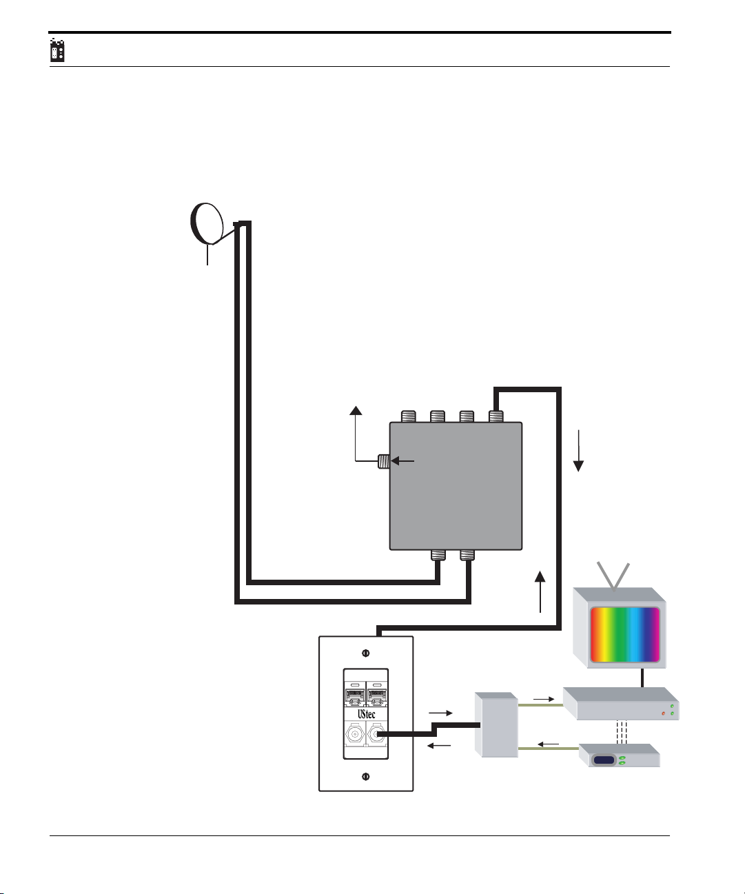
On smaller systems a CX-DSS4 system might be used. This is a 2 satellite feed
in and 4 receiver multiswitch. This allows for 4 different satellite receivers to
view signals at the same time.
CX-DSS4 is a 2 LNB input and 4 output multiswitch
for DirecTV® systems and compatible devices. The
Satellite Antenna
switch utilizes standard 13V/18V switching on LNB inputs
1 and 2. The switch is designed to be used with the
internal coax and has the ability to pass modulated feeds
from the room location for distribution throughout the
home on the same internal coaxial cable.
Modulator Feed
from rooms to
UStec CX-AMP
Internals
Phone
TV
Data
Internal
#1
Out to tecPorts
To Amplifier
Internal Input
In from Satellite
CX-DSS4
#2 #3 #4
Internal Coax
Satellite
MultiSwitch
LNB2 LNB1
CX-2060
Diplexer
Internal
Satellite
Receiver
Modulator
Satellite Signal From CX-DSS4 to room location
Modulated Signals in room return to CX-DSS4 for whole house distribution
125
Television
To Coax -orVideo Input on TV
Satellite Receiver
RCA style
Line feeds
to modulator
Modulator
58
UStec Structured Wiring Users Manual
Page 59

Satellite Television Hookup
For more questions on satellite equipment refer to the section on modules.
UStec Structured Wiring User Manual
59
Page 60

60
UStec Structured Wiring Users Manual
Page 61
Modulation and distributing video
Modulation and distributing video
tecLAN, iLAN, and iSAT models are configured to distribute your own television channels through out your home. In order to distribute your own television channels a device called a modulator is needed to turn line level signals
(the RCA style outputs on your satellite or DVD for example) into “modulated” television channels.
UStec carries a series of modulators from 1 to 3 channel (this means up to 3
devices can have their own separate channels) in mono and stereo versions.
UStec modulators have been specifically designed to work with our systems
and have the necessary dB output to drive a whole home (35dB). UStec can
not guarantee the results when using non-UStec components.
Let’s use a typical scenario to
understand how a modulator
works. Lets assume we want to
watch a DVD in every room in the
home.
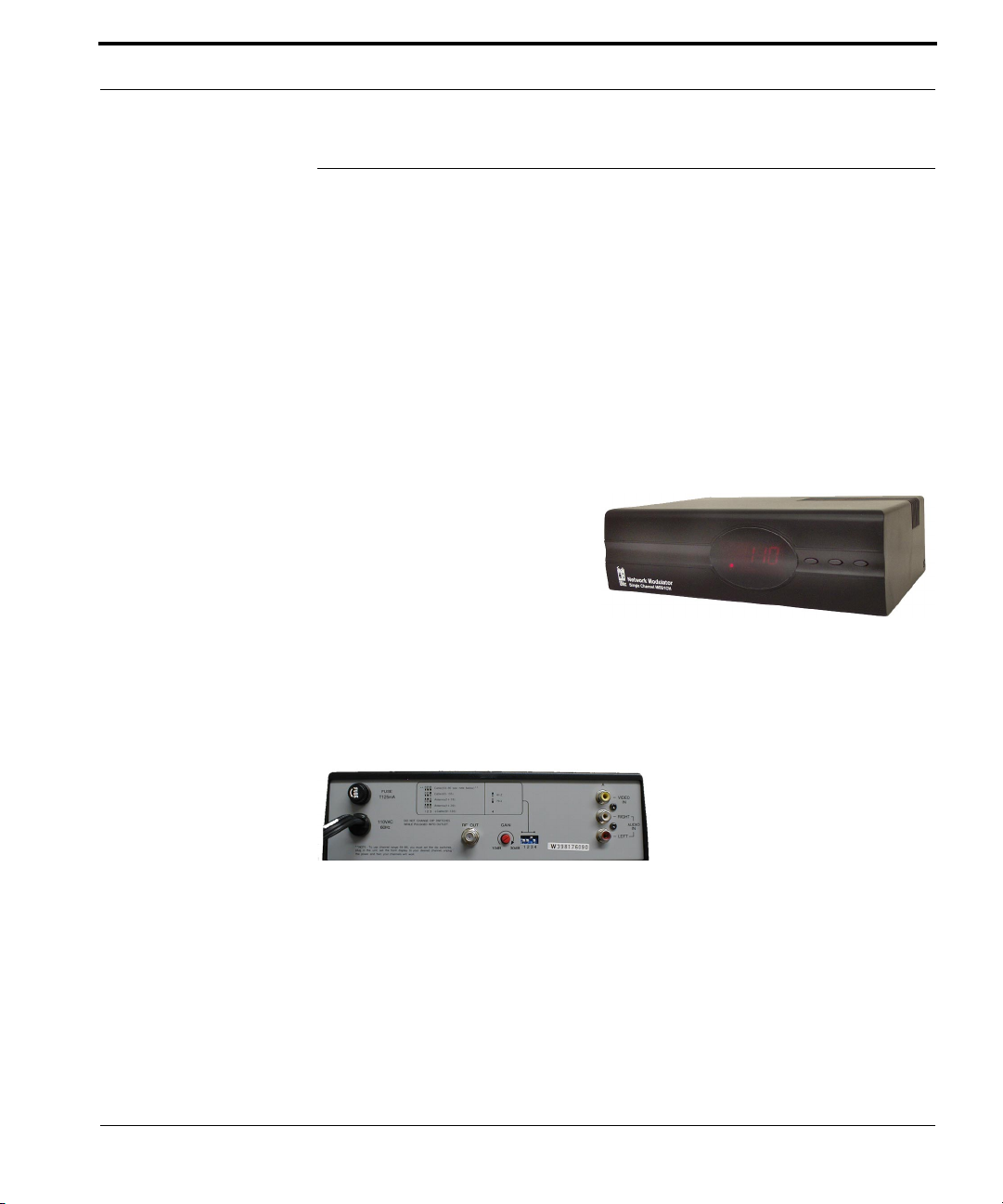
Here is the picture of the front a
of the 1 channel modulator part number MOD1CH.
Using RCA style patch cords connect the Video out on the DVD to the Video
port on the rear of the modulator (Yellow jacks). Next connect the left and
right audio from your DVD to the left and right inputs on the modulator.
This particular modulator is a
mono modulator, which means
that the left and right audio signals get mixed together. UStec
offers stereo versions if you are
interested.
On the front of the modulator select the up and down buttons and turn the
modulator to channel 120. Your UStec system has a specialized filter to block any
modulated signals from harming the cable companies return path. The return path is
where cable modems and interactive set top boxes signals go back to the cable company. Even if you do not utilize these cable services, without the filter you could effect
your entire neighborhood.
UStec Structured Wiring User Manual
61
Page 62

If you have cable television service, UStec strongly recommends modulating
to channels 118 and higher. Cable companies have been allocated to 750
MHz for their digital signals. Channel 116 ends at 750 MHz. This eliminates
any possible problem with wiping out a series of digital channels.
For those with off-air antennas you can safely modulate on channel 60 and
higher.
Power off the modulator.
Once the channel has been set (120 in our example) connect a coax cable to
the cable port on your modulator and plug the other end into the INTERNAL
port on your tecPort. Satellite users plug the modulator into the port labeled
modulator on the CX-2060 diplexer that came with your system.
Power on your modulator and device (DVD in this example)
Now your DVD should be viewable on every channel in the home on channel
120.
NOTE: You can NOT modulate to a channel that is already occupied by another
channel. If there had already been programming at channel 120 as the explanation
above, suggested would need to pick another channel that is free and at least 2 channels away such as 122.
62
UStec Structured Wiring Users Manual
Page 63
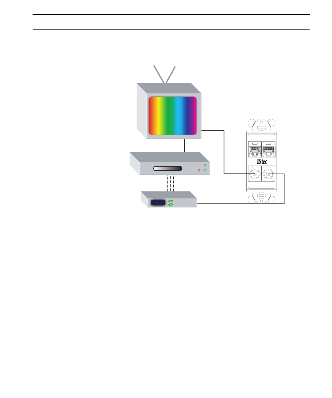
Modulation and distributing video
120
Television
To Coax -orVideo Input on TV
DVD Player
RCA style
Line feeds
to modulator
Modulator
Typical Modulator Setup
Data
Phone
TV
Internal
Here is the above steps again.
Connect the RCA feeds from the device you want to view everywhere in your
home to the modulator.
Set the channel to the desired channel (>117 with CATV or >60 on UHF)
Power down the modulator
Connect the coax output on the modulator to the Internal Input on the
tecPort, or to the port labeled Modulator if using satellite.
Power up the modulator.
Turn your TV’s to the channel set in step 2
Enjoy.
UStec Structured Wiring User Manual
63
Page 64

Set Top Box note:
One other important note here pertains to cable companies and their set-top
box. Unfortunately most of the cable companies set-top boxes are designed
to only pass their signals and to block all others. This adds one more step to
the task of distributing modulators.
If your TV has dual inputs then your problem is already solved. Connect the
raw TV feed into Antenna A (or RCA input) and the cable box into antenna B.
All your modulated signals are available on Antenna A and your set-top is on
Antenna B.
If you only have one set of inputs, then a cable box combiner kit is needed.
Contact your UStec dealer for one. This solution routes your modulated signals around the cable box to simply solve the issue.
64
UStec Structured Wiring Users Manual
Page 65

Satellite Internet Hookup
Satellite Internet Hookup
Two-Way Satellite
Satellite Internet is a still maturing market. Satellite Internet has significant
challenges most IPS do not face. This is due to the fact the signals need to
travel more than twenty three thousand miles to the satellite in orbit and
back to the ISP headend on earth before sending the return signal back to the
homeowner. This leads to large latency or delay in time for a task to be completed.
Many networked applications do not do well with long latency, so the satellite Internet companies have come up with alternative methods for making
reliable connections.
The satellite Internet companies have specialized hardware which encapsulate the normal TCP Internet packets into a more satellite friendly versions.
This makes it more difficult to share these broadband technologies than does
cable or DSL modem technologies.
Typically UStec recommends putting the broadband equipment into the tecCenter for distribution throughout the home. Due to the satellite technologies available at the time of this writing, UStec will recommend that the
satellite equipment be mounted at the location of the designated computer.
(We’ll share that computer for whole house distribution)
Later in 2002 DirecWay will have available an add-on product to its lineup
that will allow for the broadband sharing of its connection. At this time size
is still a limitation (3 different hardware boxes) so the connection will still
need to take place outside the tecCenter.
The following diagram will show how to set the computer hardware up to
share the broadband Internet connection
UStec Structured Wiring User Manual
65
Page 66
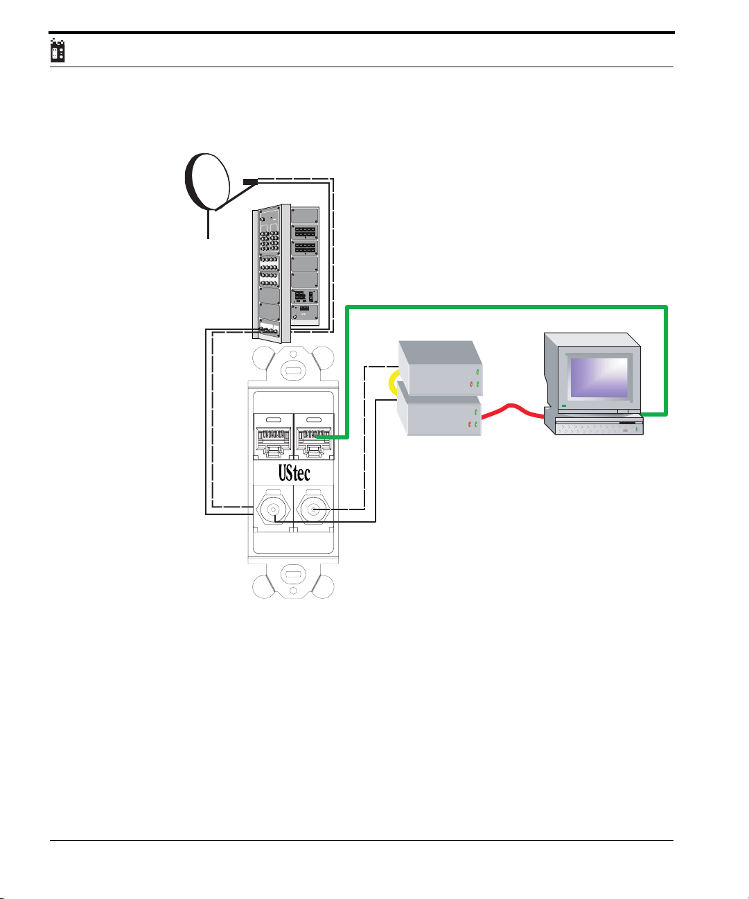
Two Way connections
Satellite Antenna
UStec Panel
Model will vary
ommended
c
Re
l Level
a
Input Sign
n
O
r
e
w
/
Po
V
T
A
C
0 - 10 dB/mV
DC
V
2
1
a
n
en
t
n
A
t
u
p
In
TPBus RJ45 Distribution Module TP-DM10R
t
u
O
V
T
TV Out
V
m
/
B
d
5
4.
+
B/mV
+7.5 d
n
i
a
G
Gain
- Retu
rge
u
S
r -
ifie
pl
F Am
R
L
A
N
R
E
T
N
I
I
N
T
E
R
N
A
L
D
S
S
&
C
a
b
le
M
o
d
e
m
O
u
t
M
Ou
t
to
DS
S
O
ut
to
DS
S
Re
cei
M
u
ve
l
t
i
s
r #
w
1
Rec
e
i
ve
r
#1
or
I
n
t
e
r
n
o
r
M
ul
tisw
I
n
p
u
it
t
ch
t
Mu
ltis
w
itc
h
LN
A
m
B
1
p
l
i
f
i
e
LN
B
1
T568A
TELCO Bus Active
TPBus RJ45 Distribution Module TP-DM10R
16
P
-AM
X
C
th
Pa
rn
T568A
TELCO Bus Active
S
4
R
IN
-
P
T
a
e
n
P
t
u
p
l
In
P
T
y
U
r
im
a
s
u
r
P
B
P
T
B
V
E
R
1
R
3
J
X
IN
i
e
L
2
n
E
T
L
O
I
C
N
A
T
C
O
1
A
D
C
O
2
5
T
A
C
3
O
R
3
J
X
1
C
T
U
O
C
O
4
i
e
L
n
1
P
O
E
W
R
T
E
L
s
B
u
C
E
C
O
F
F
O
N
O
1
C
2
V
5
D
2
/
0
m
A
1
P
0
P
T
/T
4
O
/
C
3
O
C
E
S
T
T
A
B
C
POWER
O
U
P
T
U
S
T
A
B
C
1
2
V
D
C
/
2
5
0
m
A
I
N
P
U
T
1
2
0
V
A
C
/
6
0
H
z
t
e
c
G
e
a
S
t
v
e
r
e
r
P
w
o
e
r
S
p
p
u
ly
U
X
D
-
C
6
.
o
d
u
i
t
c
h
a
l
o
r
2
l
e
C
X
D
S
S
M
O
D
E
M
O
u
t
t
o
C
a
b
l
e
M
o
d
e
m
Two -Way Satellite hookup
The two coax ports are direct connected through
the UStec panel to the two-way satellite
One coax is the receive cable from the satellite
The other is the transmit coax to send signals back to space
Data and Phone connections from the tecPort back to panel are not shown
eg. Data --> TP-10/100BT
Phone --> TP-DM10R
Ethernet Cat 5 UTP cable
Receive
Phone
Data
Transmit
USB
The transmit and receive units are interconnected.
The interconnected units are connected to the PC
running a Windows ¤ operating system via a
USB cable
Coaxial Cables
RG6
Using the Windows ¤ internet connection sharing
wizard, the satellite enabled computer becomes
TV
Internal
the gateway machine to share the high speed
access throughout the house by connecting to
the Data jack. This assumes the house has an
Ethernet network (TP-10/100BT or TP-IPR8)
Please note that the diagram does not show the connections of the phone
and data cables back at the tecCenter panel. The above diagram also assumes
their is a Ethernet switch installed in the home to share the high speed access
with other computers. (TP-10/100BT, TP-10BT, or TP-IPR8)
66
UStec Structured Wiring Users Manual
Page 67
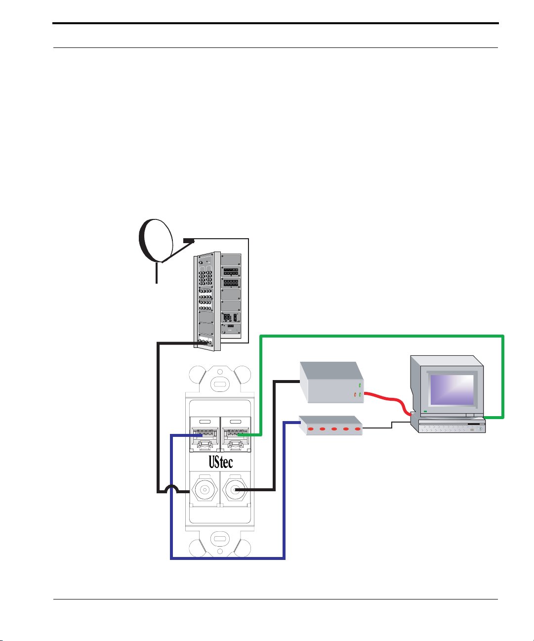
Satellite Internet Hookup
One Way Satellite
DirecPC has been around for some time with it’s one way satellite connection. In this method high speed Internet is delivered to the homeowner via a
satellite dish, but the upstream signals (from the homeowner back to the ISP)
return on a standard dial up telephone modem. Windows software from
Windows 98 second edition through the current Windows XP have a setup
wizard that allows for the sharing of this connection. Below is the diagram for
the high speed hardware connections.
Satellite Antenna
UStec Panel
Model will vary
Recommended
Input Signal Level
n
r O
e
w
o
/
P
V
T
A
C
0 - 10 dB/mV
C
D
V
12
a
n
en
t
n
A
t
u
p
In
t
u
O
V
T
TV Out
V
/m
B
d
.5
4
+
+7.5 dB/mV
in
a
G
Gain
16
P
M
-A
X
ath C
n P
tur
e
e - R
urg
r - S
lifie
p
m
A
F
R
L
A
N
R
E
T
N
I
I
N
T
E
R
N
A
L
D
S
S
&
C
a
b
l
e
M
o
d
e
m
O
u
t
M
o
d
u
l
e
C
X
D
S
S
M
O
D
E
M
O
ut to DSS
Out to DSS
Rec
M
eiver #1
u
l
t
i
s
w
i
t
c
h
Receiver #1
O
u
t
t
or
I
o
n
t
e
r
n
a
l
or
M
u
C
ltis
a
b
I
l
n
e
wi
p
u
tch
t
t
o
M
ultiswitc
h
M
LN
o
d
A
e
m
m
B1
p
l
i
fi
e
r
L
NB
1
TPBus RJ45 Distribution Module TP-DM10R
TPBus RJ45 Distribution Module TP-DM10R
T
E
L
C
O
IN
R
3
J
1
X
L
in
e
1
T
E
L
/
C
3
O
TELCO Bus Active
TELCO Bus Active
y
a
r
im
s
u
r
P
B
P
T
R
J
3
1
X
in
e
L
2
C
O
C
O
C
O
C
O
u
C
E
s
B
C
O
F
O
F
N
O
1
/
P
T
0
P
T
4
O
C
T
T
E
S
A
B
POWER
O
U
P
T
U
S
T
A
1
2
V
D
C
/
2
5
0
I
N
P
U
T
1
2
0
V
A
C
/
6
0
H
z
e
c
G
t
a
t
e
S
e
r
P
v
e
r
w
o
One-Way Satellite hookup
The internal coax port is direct connected to the
T568A
internet satellite LNB
T568A
Data and Phone connections from the tecPort back to panel are not shown
eg. Data --> TP-10/100BT
Phone --> TP-DM10R
S
4
R
IN
-
P
T
a
P
e
n
t
u
p
l
In
P
T
U
B
V
E
R
IN
A
T
1
A
D
2
5
T
A
3
C
T
U
O
4
P
O
W
E
R
2
1
V
D
C
/
2
0
5
m
A
C
B
C
m
A
S
e
r
p
p
u
l
y
U
-
X
D
C
6
.
2
Ethernet Cat 5 UTP cable
Phone
Data
Telephone Modem
The receive unit is connected to the PC
running a Windows ¤ operating system via a
USB cable. The upstream back to the ISP is via
Coaxial Cable
RG6
a standard dial up telephone modem.
Using the Windows ¤ internet connection sharing
wizard, the satellite enabled computer becomes
TV
Internal
the gateway machine to share the high speed
access throughout the house by connecting to
the Data jack. This assumes the house has an
Ethernet network (TP-10/100BT or TP-IPR8)
UStec Structured Wiring User Manual
Receive
USB
67
Page 68

68
UStec Structured Wiring Users Manual
Page 69
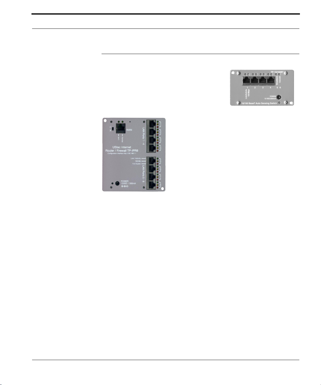
Computer Networking
Computer Networking
UStec provides two methods for computer networking via the TP-IPR8 8 port router module
and the TP-10/100BT Ethernet switch module.
Please see the documentation that is included
with these units.
There are complete manuals on the networking
products available via the UStec website.
Product manuals for the TP-IPR8 and TP-10/100BT
are available in the technical support section of the
website.
There is also full networking documentation in the
document entitled Networking and tecSystems in
the support section
http://www.ustecnet.com
UStec Structured Wiring User Manual
69
Page 70

70
UStec Structured Wiring Users Manual
Page 71
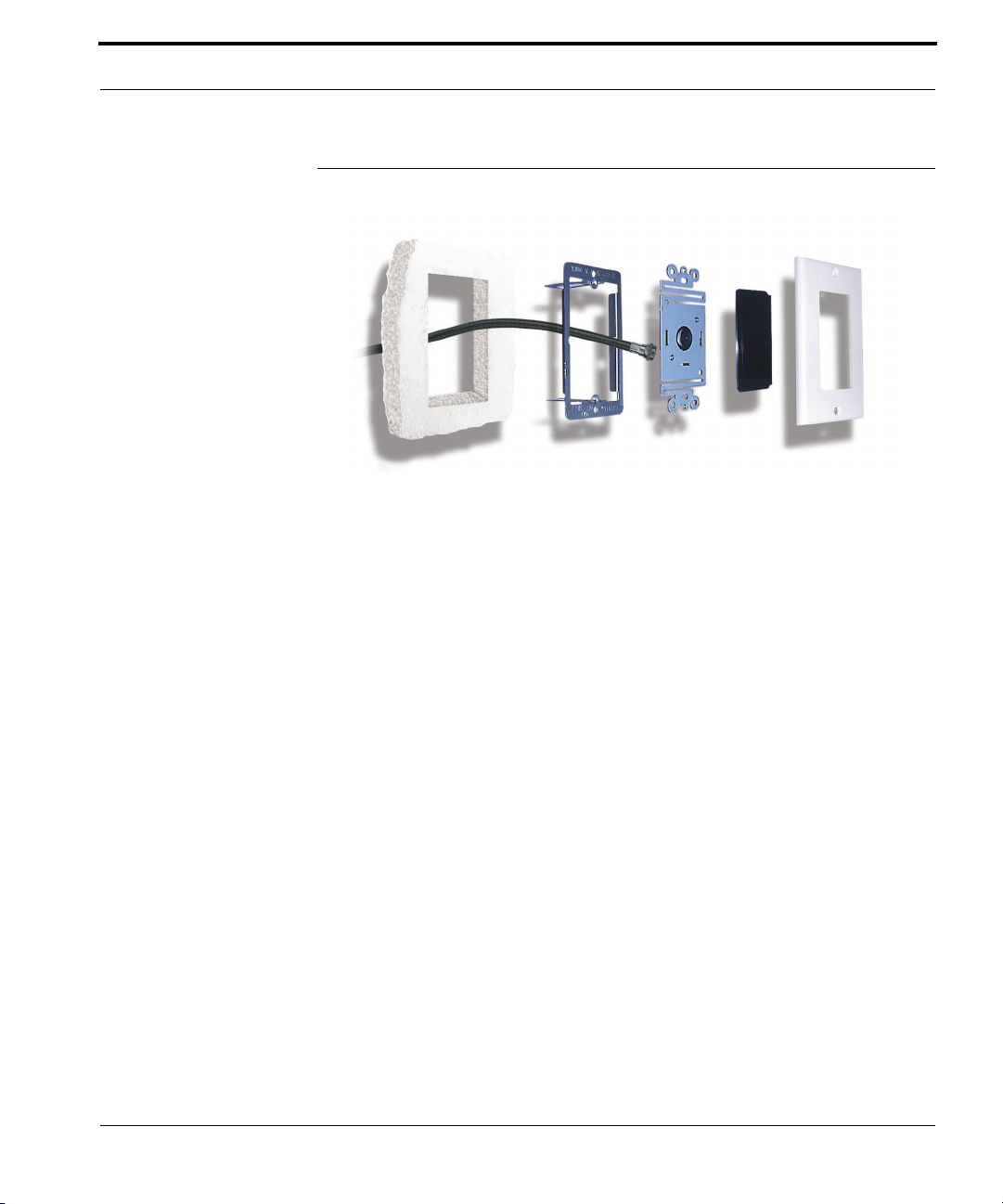
Surveillance Cameras
Surveillance Cameras
tecLAN, iLAN, and iSAT models are configured to distribute your own television channels through out your home. If you read the previous section on
distributing video you now have an idea on how to create your own television channel in your home. UStec offers surveillance cameras that are cameras with integrated modulators.
UStec currently carries an in-wall camera that is available in both black and
white and color versions. In addition there is a outdoor floodlight style camera that is available in both black and white and color. This version also offers
audio.
All that is required to wire for one of these cameras is one RG6 coaxial cable.
These cameras receive their power over the coax cable and send the modulated camera feed back to the UStec tecCenter for distribution through out
the home.
These cameras are perfect as surveillance for the front and rear doors, garage
areas, backyards. etc. Use one to watch the pool, use one with audio as a baby
or child’s play room monitor. The cameras are an easy way to add piece of
mind.
A camera is typically sold with the CX-CM4 camera power module. More
details on this hardware as well as camera hardware is available in the modules section later in this guide.
UStec Structured Wiring User Manual
71
Page 72
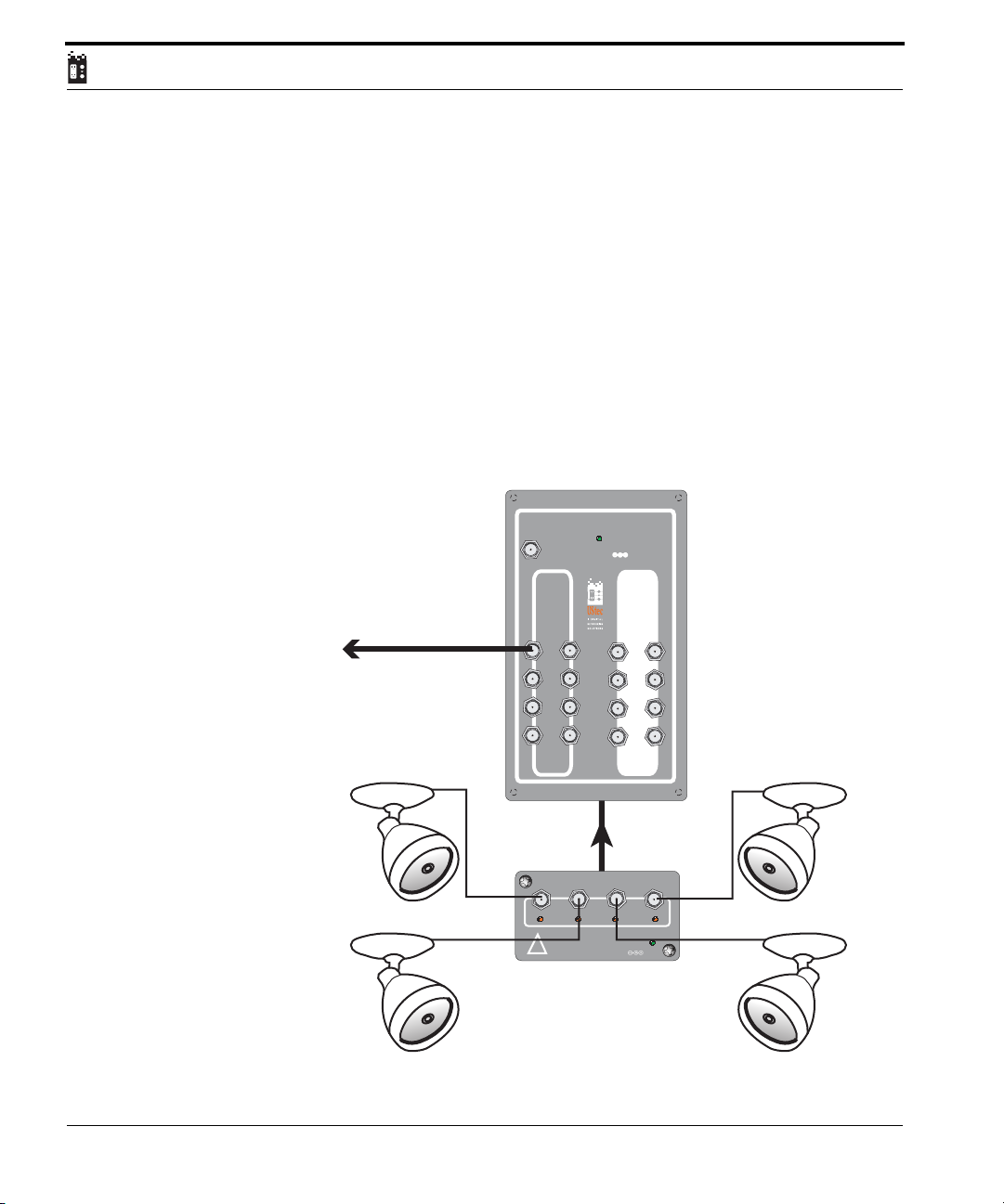
Using the example in the previous section, lets add the modulated camera to
the mix.
Modulated signals need at least one channel of separation. In the distributing
modulators section we shared a DVD throughout the home on channel 120.
Lets share the camera then on channel 122. (1 channel spacing)
The camera should be installed by a certified UStec dealer. The camera’s channels are adjusted by pushing a series of dip switches on. For channel 122 we
will turn on dip switches 80, 40 and 2. (80+40+2=122). For more detailed
technical information please see the technical section on the UStec website.
The diagram below shows a 4 cameras setup on channels 118, 120, 122, and
124.
RecommendedRecommended
Input Signal Level
0 - 10 dB/mV0 - 10 dB/mV
CATV/
Antenna
Input
TV Out InterInternalnal
Power On
12VDC
CATV &
Channels
118,120,
122,124
72
RF Amplifier - Surge - Return Path CX-AMP8.1
Channel
118
#1 #2 #4#3
Channel
120
UStec Structured Wiring Users Manual
Caution: Do Not
Terminate Camera
Ports With 75 Ohm
!
Terminator Caps
CamerCamera Pa Power Module CX-CM4er Module CX-CM4
Camera Inputs
Power
12VDC
4 @ 300 MA
Channel
122
Channel
124
Page 73
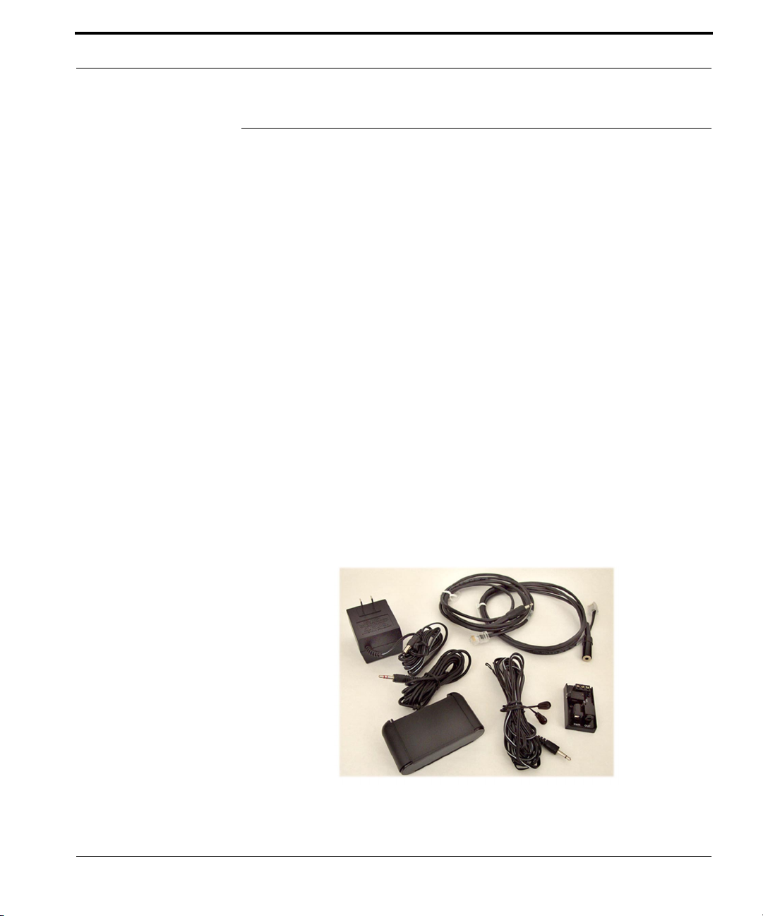
Infrared Remote Controls
Infrared Remote Controls
When a whole home IR remote control system is not installed or warranted, a
UStec remote control system (IR-KIT) is a easy way to control your IR enabled
devices from another room.
Using the example of the modulated DVD system in the distributing video
section, you want to not only view the DVD player on channel 120, but want
to be able to control it from the master bedroom. An IR remote control system would allow for complete control of the DVD player via the master bedroom.
The system is broken down into two parts. The first part is the receiver system
that receives the invisible pulses of light from the remote control. This
receiver system converts light energy into electrical energy that we can transport over the UStec structured wiring system.
The second part of the system is the emitter system. This converts the electrical energy back into the light pulses your equipment (DVD) expects to see. A
small emitter is affixed to the IR window on your hardware (DVD in this
example).
Below is an image of both parts.
UStec Structured Wiring User Manual
73
Page 74
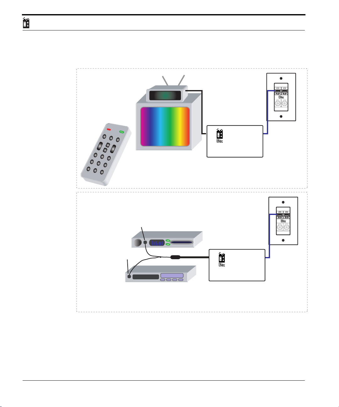
Wiring Hookup Example
Master Bedroom
IR Receiver
Line
Out
tecFlex
Line Chooser
Module - UB4.5
www.ustecnet.com
L4/L3
*optional
TM
L3/L4 L2/L1 L1/L2
DataTVPhone
Internal
Line
In
Entertainment Center
DataTVPhone
IR Window
DVD Player
Internal
*optional
TM
IR Window
Line
Out
tecFlex
Line Chooser
Module - UB4.5
www.ustecnet.com
Line
In
VCR Player
12:00 AM
L4/L3
L3/L4 L2/L1 L1/L2
NOTE: The IR system runs on the brown pair (Line 4). It can NOT co-exist if there is already a telephone
number on that line. (KSU systems typically do not apply)
*The tecFlex line chooser is only required if telephone line access is desired at the same location as the
IR Kit.
74
UStec Structured Wiring Users Manual
Page 75

Audio Distribution
Audio Distribution
UStec’s AU-2X4 in conjunction with third party speaker wires, speakers and
impedance matching volume controls allows for the distribution of whole
house audio.
The AU-2X4 allows for the distribution of one A/V receiver/amplifier to at
least seven different room locations. Wires from the A/V receiver/amplifier
input into the AU-2X4 and are sent out to various rooms speaker controls.
From there they are wired to your speakers.
The AU-2X4 can also be configured for two zones by removing the shorting
jumper between the top and bottom rows of connectors. This allows for two
separate receiver sources out to at least three rooms each.
This unit works by sending the left and right amplified audio outputs from an
amplifier or integrated amplifier/receiver to the first connection point on the
AU-2X4. The are wired to L+, L- & R+, R-.
The AU-2X4 is now active and each corresponding room can be connected.
The amplified left and right audio outputs travel to the room where they connect with an impedance matching volume control. This device matches the
impedance of the speakers to that of the amplifier or integrated amplifier/
receiver that is driving the system.
The speakers in the room are then connected to the impedance matching volume control.
The following two illustrations demonstrate these connections.
UStec Structured Wiring User Manual
75
Page 76
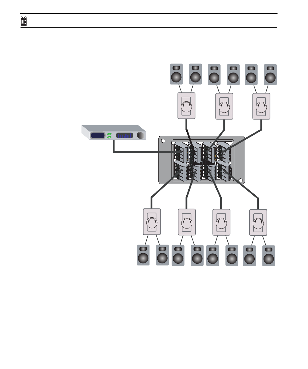
Single Zone System
Stereo Receiver
91.5
Volume
Source
Source
2
Volume
AUBus 2x4-Way Module AU-2x4
L+
LR+
1
R-
L+
LR+
R-
Volume
Volume Volume
L+
LR+
R-
L+
LR+
R-
Volume
Volume
76
UStec Structured Wiring Users Manual
Page 77
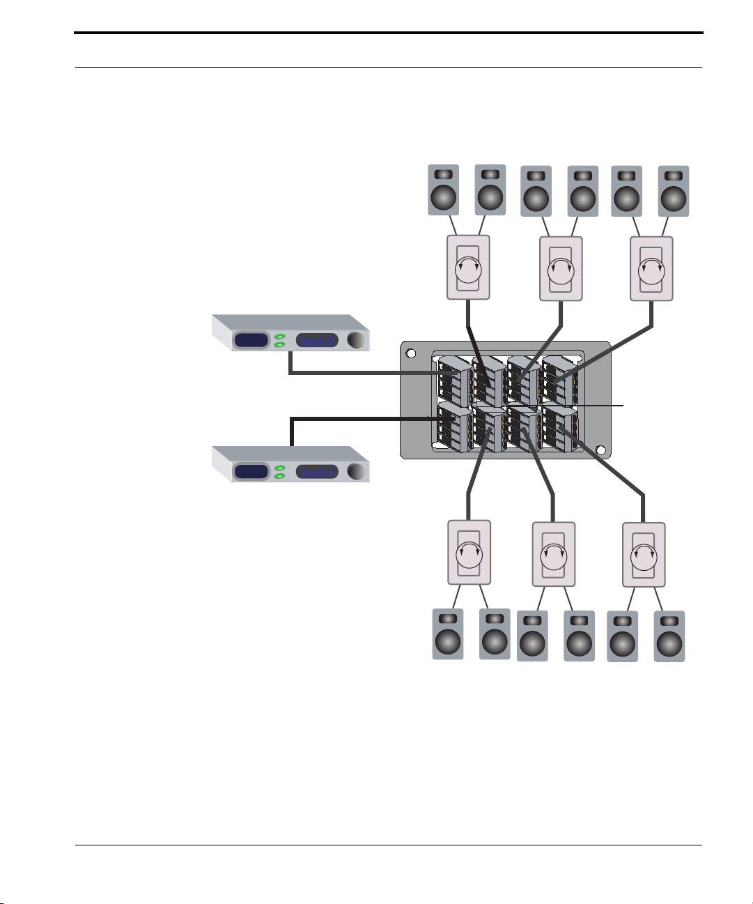
Audio Distribution
Dual Zone System
Stereo Receiver
91.5
Stereo Receiver
89.5
Source
1
Source
2
Volume
AUBus 2x4-Way Module AU-2x4
L+
LR+
R-
L+
L-
R+
R-
Volume
Volume Volume
L+
LR+
Volume
R-
L+
LR+
R-
JUMPER
REMOVED
Volume
UStec Structured Wiring User Manual
77
Page 78

78
UStec Structured Wiring Users Manual
Page 79

Third Party equipment examples
Third Party equipment examples
Your UStec system is ready to handle all kinds of technologies. This section
shows a couple of interesting technologies that can be easily integrated into
your system. This section assumes you have Ethernet capability which is standard in any iLAN or iSAT system, and is optional in tecLAN or tecSAT systems.
IP cameras
Imagine being able to see your who’s at your front door from work, or check
on the baby-sitter or see who’s using your pool when you are half way around
the world. It can be done with an IP based network camera and a broadband
connection. There are several manufacturers of the cameras. Two examples
are Panasonic and Axis communications.
These cameras are setup just like any other camera except they output via
Ethernet. With an IntelliWAY server or the TP-IPR8 router, you can make these
cameras visible on the Internet. Please refer to each products corresponding
documentation for detailed instructions.
When you are away from home simply type in the WAN address of your IntelliWAY or TP-IPR8 and port number you specified in the IntelliWAY or TPIPR8. You will now see and have control of your cameras from any Internet
connected computer anywhere in the world.
MP3 Player
Enjoy a collection of music practically as large as you can make it. With an
MP3 player and an A/V receiver or amplified speakers you can listen to the
thousands of songs in your library.
An MP3 player is a device like a CD player that plays your music. Where the
difference lies is that your songs are converted to the MP3 audio format and
streamed over your Ethernet network. These songs can be stored on hard
disks on any connected machine or on the IntelliWAY if you have one. You
could put more than ten thousand songs on your Intelliway hard drive.
To connect an MP3 player there are three connections. The first is a power
cable to plug into any outlet. The second is RCA or optical outputs for you’re
UStec Structured Wiring User Manual
79
Page 80

A/V receiver or amplified speakers. The last connection is an RJ45 Ethernet
connection that plugs into your network.
Most units on the market will automatically search the network for songs and
be ready for use with little or no work at all. Additionally they usually come
with software that allows you to convert your CD’s to MP3 files and make any
necessary adjustments to the system.
As with most computer components, MP3 players are not too expensive, and
if history is any indication it will be cost effective to have several on your network for different rooms in your house.
The Future
There is probably a hundred other things we could put in here, a hundred
new things in a year, and you have a hundred more. With the infrastructure in
the walls with your UStec system, these technologies will be easy to integrate.
80
UStec Structured Wiring Users Manual
Page 81
UStec Modules
UStec Modules
The following section describes UStec modules more in depth for those who
want more information about the components that make up their UStec system. UStec products are constantly evolving as we look to improve them and
adapt or design new technologies.
The latest and most up to date information on UStec products are available in
the technical support section of the UStec website.
http://www.ustecnet.com
Panel Modules
The tecGate panel assembly is assembled at the factory in either a stock or a
user-defined configuration. When the panel is purchased as part of a system,
on-site configuration is not required; simply terminate the wires and plug
them into the correct ports on the tecGate panel.
Some on-site configuration may be required when upgrading tecGate Servers,
for example, making the connections to install a new module(s). The table
below lists the available modules, part numbers, and applications.
TABLE 1.
Designation
Application
(Part No.)
Amplified Coax
Module
Amplified Coax
Module
UStec Structured Wiring User Manual
CX-AMP16 Provides input for CATV, up to 4 internal con-
nections. (32 with CX-DM8Module) Routes combined internal / external signals to up to 16 TV
ports on tecPorts. Provides surge protection for
all outgoing signals at 6 KV per port. (per IEEE
C62.41-1999)
CX-AMP8 Provides input for CATV, up to 11 internal con-
nections. Routes combined internal / external
signals to up to 8 TV ports on tecPorts. Provides
surge protection for all outgoing signals at 6 KV
per port.(per IEEE C62.41-1999)
81
Page 82
TABLE 1.
Amplified Coax
Module
Passive Coax
Module
Internal 8-Way
CX Module
Satellite Multiswitch
Satellite Multiswitch
Satellite Multiswitch
Camera Module CX-CM4 Designed for use with UStec cameras. The cam-
Audio Speaker
Hub
Power Supply UX-DC6.2 Provides low voltage power to the system. Stan-
TP Input Module TP-IN4RS Input for TELCO service. Provides auto reset
TP Module
(Standard)
TP Module TP-DM10B Provides parallel telephone distribution to 10
KSU Module
CX-AMP1X8 Provides input for CATV Routes incoming sig-
nals to up to 8 TV ports on tecPorts. Provides
surge protection for all outgoing signals at 6 KV
per port. (per IEEE C62.41-1999)
CX-4X4U
CX-4X4U.1
CX-DM8 (2) Used with CX-AMP16. Combines internals
CX-DSS4 Satellite multiswitch for dual LNB satellite
CX-DSS58 HD compatible satellite multiswitch for up to 8
CX-HDA58 HD compatible satellite multiswitch for up to 8
AU-2X4 Passive audio distribution module. Eight stereo
TP-DM10R Provides parallel telephone distribution to 10
TP-KSU8 KSU phone system integration module. Provides
Passive distribution of CATV, up to 4 internal
connections to up to 4 TV ports on tecPorts
for insertion into amplifier.
dishes, up to 4 receivers.
receivers, active internal return path (for use
with AMP 8 / AMP 16)
receivers, active internal return path, includes 8way passive splitter for use with terrestrial antennas.
eras come in indoor and outdoor versions. One
RG6 coax is all that's needed to pre-wire. Powers
up to 4 cameras.
jacks are mounted in parallel for signal distribution. Does not provide impedance matching.
dard module on all iLAN/ iSAT Series.
surge protection to four telephone lines. Has
Category 5 pass-through jack for ISDN and other
digital point to point services, 2 RJ31X interfaces
for security or automation devices. CEbus compliant.
ports. Interfaces with TP-IN4RS via RIB24 and
RIB26 ribbon cables, or can be used stand-alone.
ports. Used as stand alone only; cannot be interfaced with TP-IN4RS
interface between room runs and KSU switch via
TP-KSU624 or TP-KSU1232 adapter cable
82
UStec Structured Wiring Users Manual
Page 83
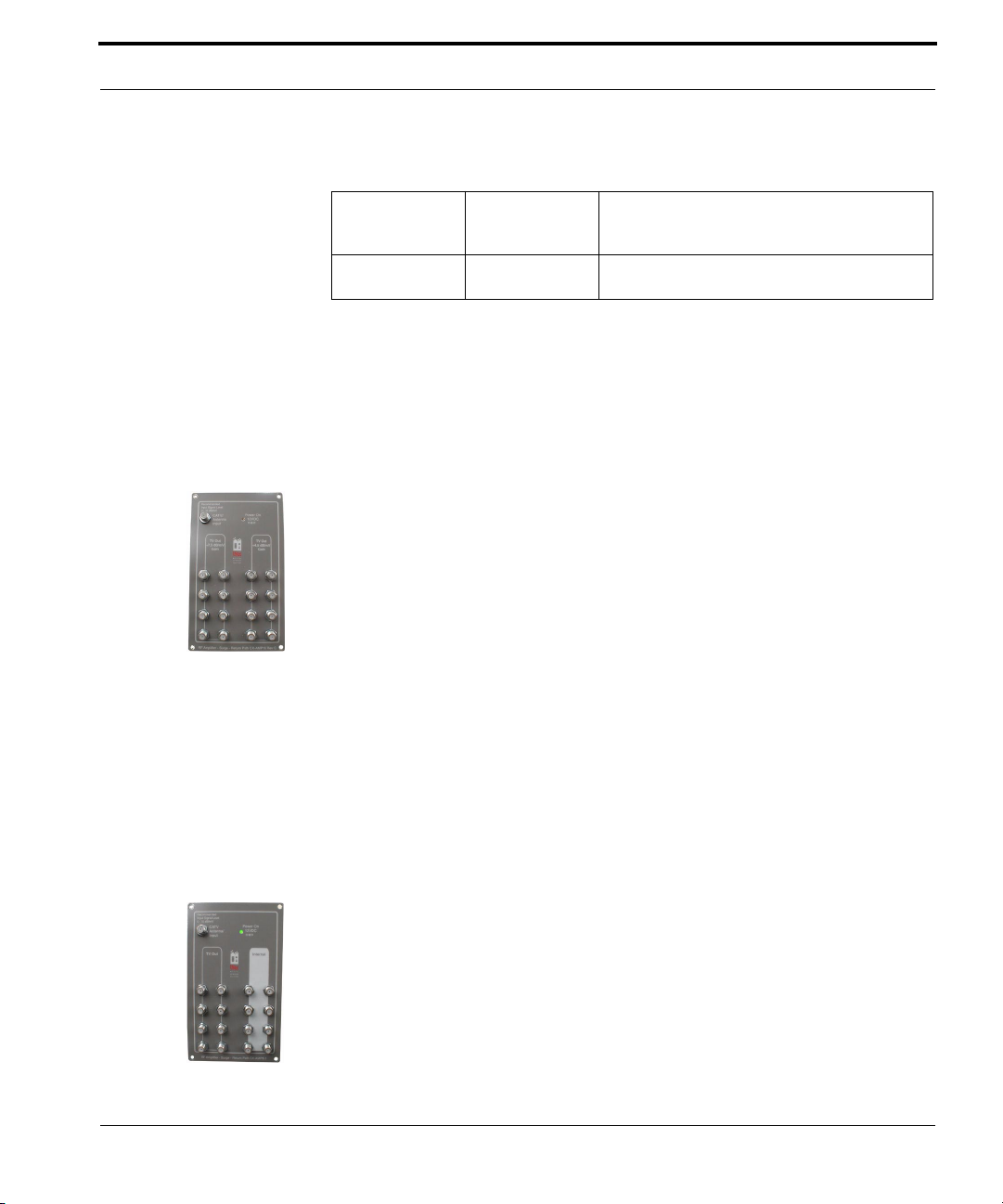
UStec Modules
TABLE 1.
Computer 10/
100BaseT Ethernet Switch
Computer 8 Port
switched router
TP-10/100BT Auto sensing Ethernet switch networks up to 4
devices, with two cascade ports for cascading
additional 10/100 switches
TP-IPR8 Auto sensing 8 port Ethernet switch, with WAN
port for sharing high speed Internet access
The tecGate panel modules are described on the pages that follow.
Amplified Coax Module CX-AMP16
The CX-AMP16 amplifier is the 16 port version of the highly regarded CXAMP8.
This amplifier has a single CATV input with 16 outputs. The outputs are separated into banks of eight. One bank of eight outputs features +7.5 dB gain to
compensate for the longer cable runs that are typical in larger networks that
utilize the CX-AMP16. The second set of outputs are +4.5dB. As with the CXAMP8, the goal is unity gain – reproduction of incoming signal strength at the
tecPort.
The AMP16 also has 2 inputs on the rear of the device (labeled CX-DM8) for
the connection of the internal leg of the network, and 2 spare input (labeled
AUX) for future integration.
The module also provides 6 KV surge protection for all outgoing signals.
Amplified Coax Module CX-AMP8
The AMP8 looks similar to the CX-AMP16, but instead of a second bank of
eight OUTPUTS there is a bank of eight INTERNALS. This allows connection
of up to 8 dual coax runs to be terminated directly to the amplifier.
The 8 outputs are unity gain – when tested, signal strength at the TV port on
the tecPort should be similar to the incoming signal strength at the CATV in
port on the AMP8.
UStec Structured Wiring User Manual
83
Page 84
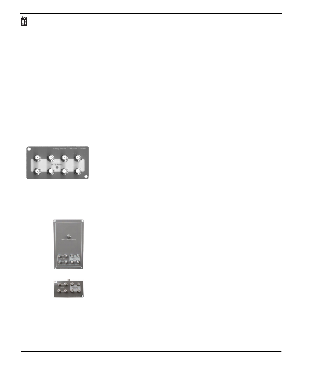
The 8 inputs on the face of the AMP8 are for the connection of the internal
(white) leg of the coax network. Signals returned to the internal inputs are
combined first with each other, then with incoming CATV signal. This composite signal is then fed into the amplifier for distribution on the TV (black)
leg of the network.
There are 3 additional internal inputs on the rear of the amplifier for connections to DSS multiswitches, camera modules, or future devices. These inputs
function identically to the front internal ports.
The module also provides 6 KV surge protection for all outgoing signals.
Internal 8-Way CX Module CX-DM8
The CX-DM8 module is used with the CX-AMP16. This module serves as a
connection point for the internal (white) cables.
The CX-DM8 combines up to 8 internal (white) cables into one composite
feed and passes it to the “CX-DM8” input on the rear of the amplifier so
they can be combined with other incoming signals and the CATV signal for
insertion into the amplifier.
CX-4X4U & CX-4X4U.1 Distribution Modules
84
Intended for the MDU and small production market, the CX-4X4U module is
a cost effective yet extremely high quality cable distribution system. It has all
the functionality of the CX-AMP8 and CX-AMP16 modules, including surge
suppression.
The CX-4X4U.1 is the same module as the CX-4X4U mounted to a larger faceplate.
As indicated by its part number, the CX-4X4U provides termination points for
up to 4 dual coaxial runs. Unlike the AMP8 and AMP16 however, the 4X4U is
a passive (non amplified) module.
These modules also have 6kV surge protection.
UStec Structured Wiring Users Manual
Page 85
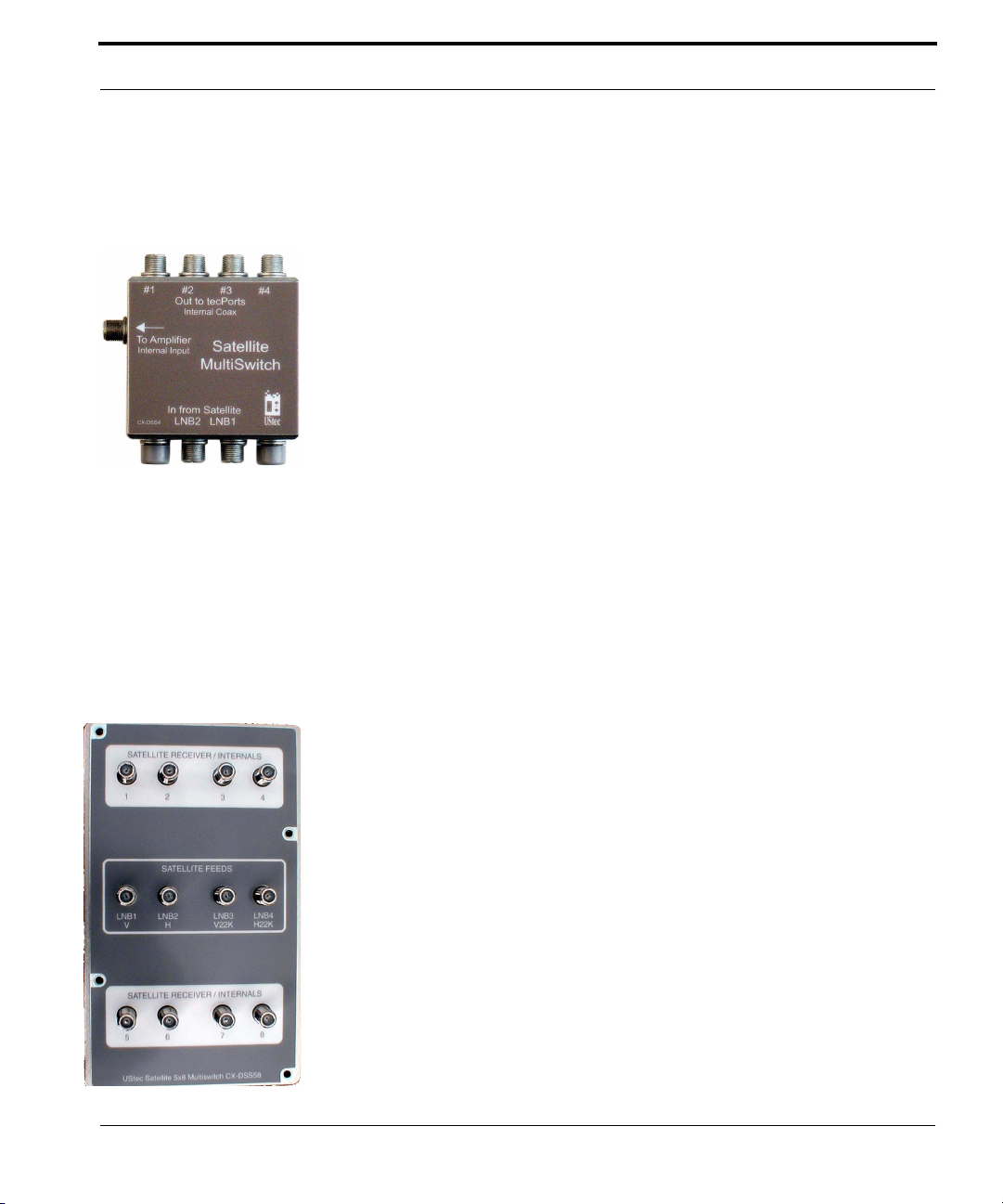
UStec Modules
Satellite Multiswitch CX-DSS4
The CX-DSS4 is a dual LNB multiswitch for use with standard (non-HDTV)
DSS dishes and receivers. It features dual LNB inputs, and four outputs for
connection of up to four non-HDTV, DirecTV compatible tuners. The CXDSS4 can be mounted in the UX-10x enclosure in two different places
depending upon the panel module used
The CX-DSS4 also has a terrestrial port, labeled “to amplifier internal input.”
This port is connected to any of the internal inputs on a UStec coax distribution module (CX-AMP8, CX-AMP16, CX-4X4U) when the internal (white)
leg of the dual coax network is used in bi-directional mode.
Installers familiar with satellite multiswitches typically use the terrestrial port
to combine an off-air antenna or cable with satellite signals over one coax to
the room location.
UStec uses a different approach. Instead of using the terrestrial port for cable,
we use it as an internal return path. This is done for one very important reason−Quality. Satellite equipment is not designed to handle broadband cable
connections. In fact, most satellite equipment is designed to handle 16 or less
terrestrial channels, and few if any cable systems in North America fit this
description. Instead, UStec uses the terrestrial side for feeding modulated signals back to the tecGate panel
Satellite MultiSwitch Module CX-DSS58
The CX-DSS58 is an eight output HDTV compatible multiswitch. When used
with an HDTV compatible dish, any combination of up to eight HDTV and
non-HDTV receivers may be used.
The CX-DSS58 is designed to use the internal cables bi-directionally; by distributing satellite signals out to eight rooms while maintaining the ability to
send modulated signals back on the same coax. Modulated signals that return
to the multiswitch are amplified to ensure good modulator signal strength,
then routed to the amplifier.
The CX-DSS58 is included in iSAT series servers for installation in homes that
subscribe to both CATV and DSS. It takes three module bays in the panel, and
UStec Structured Wiring User Manual
85
Page 86
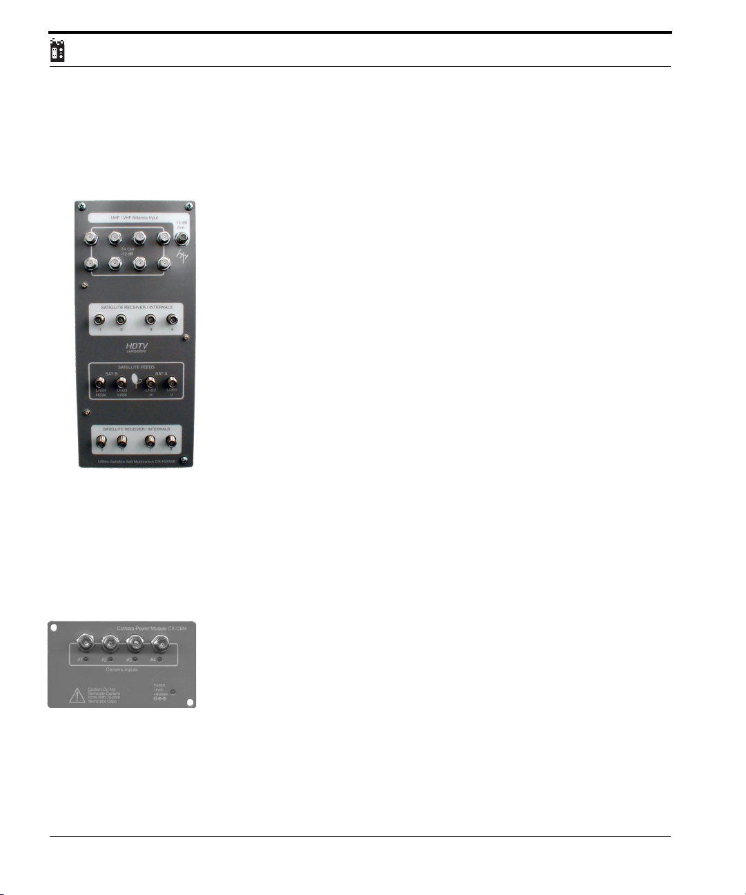
is installed from the rear of the frame. When used with the CX-AMP16, the
CX-DSS58 replaces one CX-DM8 module.
Satellite MultiSwitch Module CX-HDA58
This is an eight output HDTV compatible multiswitch. When used with an
HD compatible dish, any combination of up to eight HDTV and non-HDTV
receivers may be used.
In addition to its function as a multiswitch, it also has a 1X8 passive splitter
intended for the distribution of terrestrial antenna signals. It is not recom-
mended that the CX-HDA58 be used for the distribution of broadband CATV signals.
The CX-DSS58 is designed to use the internal cables bi-directionally; by distributing satellite signals out to eight rooms while maintaining the ability to
send modulated signals back on the same coax. Modulated signals that return
to the multiswitch are amplified to ensure good modulator signal strength,
then routed to the 1X8 passive splitter.
The CX-DSS58 is included in iSAT series servers for installation in homes that
subscribe to DSS, but receive local programming via terrestrial antenna. The
CX-HDA58 does not fit into the 20K2562 panel frame (FX-200).
86
An antenna pre-amplifier is strongly recommended for any antenna connected to the
antenna input port.
Camera Module CX-CM4
The camera module is designed expressly for use with UStec indoor and outdoor surveillance cameras. It is capable of powering up to 4 cameras. Power is
supplied to the cameras from the UX-DC6.2 low voltage power supply,
through the RG6 coaxial cable, to connectors on the rear of the camera module. The coaxial cable inputs from the cameras connect to the face of the camera module. The output from the camera module connects to the internal
port on the internal CX amplifier.
All that is needed to prewire this system is a single RG6 feed per camera. The
cameras themselves consist of a high quality CCD (charge coupled device)
sensing unit and a built-in modulator. The CX-CM4 module supplies 12 volts
UStec Structured Wiring Users Manual
Page 87
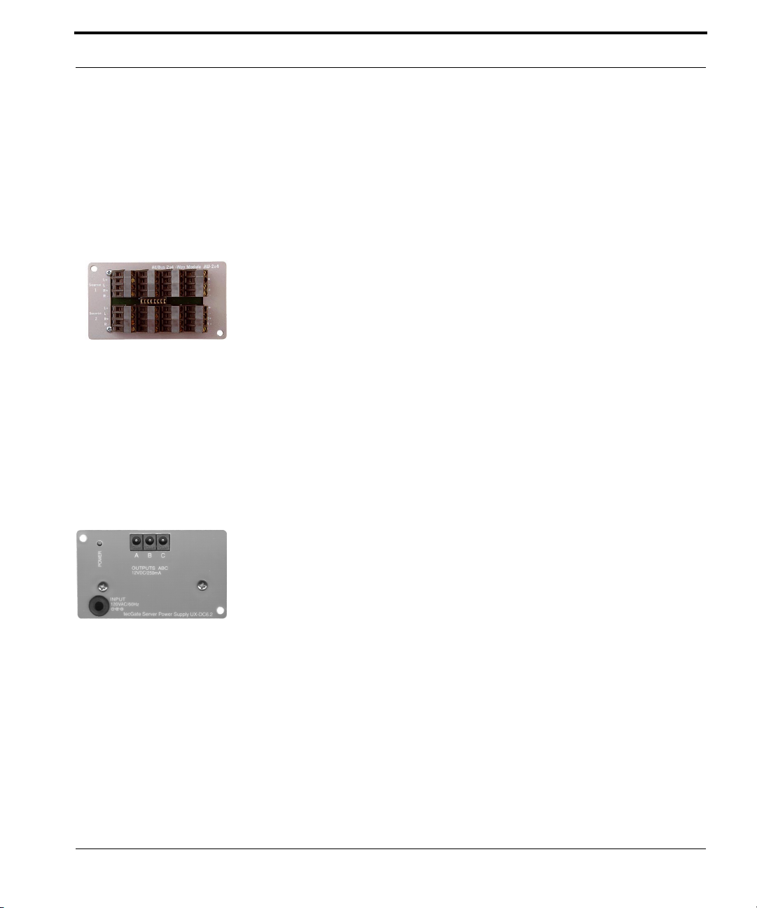
UStec Modules
regulated DC, which powers the modulator and camera. The camera, in turn,
sends back the modulated camera output on a channel you select. The CXCM4 will combine that signal with the signals from up to three other cameras
and distribute the signals to one internal on a UStec coaxial distribution
module (CX-AMP16, CX-AMP8, CX-4X4U).
Audio Speaker Hub Module AU-2X4
The AU-2X4 is a passive audio speaker distribution hub that consists of eight
stereo wire connectors wired in parallel. The device can be set up in either of
two ways:
Bring a stereo source from an amplifier into the Source 1, and output to seven
different locations by way of impedance matching speaker knobs in the
rooms.
Remove the bridging adapter between the two rows of connectors to have two
separate sources that feed three rooms each.Because this device is a passive
patch panel, it also can be used for other purposes, e.g., as a central hub for IR
controls. The unit can connect wires from 10 to 28 gauge.
Power Supply Module UX-DC6.2
The UX DC6.2 is the latest revision of the DC power supply.
This power supply has three 2.5 millimeter by 5.5 millimeter plugs on the
front, plus two additional two-pin power connections on the rear.
These features allow panel modules to take advantage of “bus” type power
cords which run up the back side of the panel frame and enhance the appearance of the panel. Each power bus cable has connectors for applying power to
individual modules in series.
The UX-DC6.2 also features a dealer replaceable 1/2 amp 250 volt slow-blow
fuse (Littlefuse # 229.500S). It also provides a ground post on the rear of the
unit for the TP-IN4RS telephone input module, as well as previous generation
amplifiers.
The UX-DC6.2 is unregulated, as different modules require different voltages.
Therefore, any device connected to it must have voltage regulation.
UStec Structured Wiring User Manual
87
Page 88
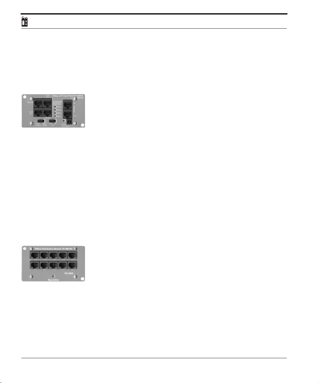
The total current capacity of the UX-DC6.2 is 1700mA. The current output of
individual ports is not restricted, as long as total current draw does not exceed
1.7 Amps.
TP Input Module TP-IN4RS
The TP-IN4RS is a telephone line interface and surge suppression module.
Connections are present for incoming CO lines, dial tone out to a KSU phone
system, two RJ31X-enabled devices, and a Category 5 rated coupler.
CO Lines entering the panel are connected to the TELCO IN jack. All four
pairs are distributed to the TP distribution module(s) via the ribbon cable
connectors on the rear.
Surge protected dial tone can be sent to a KSU phone system via the KSU
OUT jack.
Two RJ31X devices may be connected; one each on lines 1&2. Due to sensitivity of some RJ31X – capable devices and legal liability, surge suppression is
not applied to the RJ31X jacks.
Two devices requiring a Category 5 rated coupling may be connect to the CAT
5 DATA jacks.
88
TP Module TP-DM10R
The TP-DM10R is a 10 port RJ45 distribution module that replaced the TPDM6R module (shown on next page). In addition to having four more RJ-45
ports, the unit is wired in parallel, allowing it to operate on its own, without
the need for ribbon cables and a TP-IN4 module.
The primary benefits of this design are that it can be used as a standalone
device, or it can be used in the event of a catastrophic failure of a TP-IN4
module, or it can be connected in the same manner as a DM6R module.
This device cannot be used with KSU systems because it is wired in parallel.
This does not apply to KSU-less systems or to KSU systems that do not need
independent pairs of wires.
UStec Structured Wiring Users Manual
Page 89
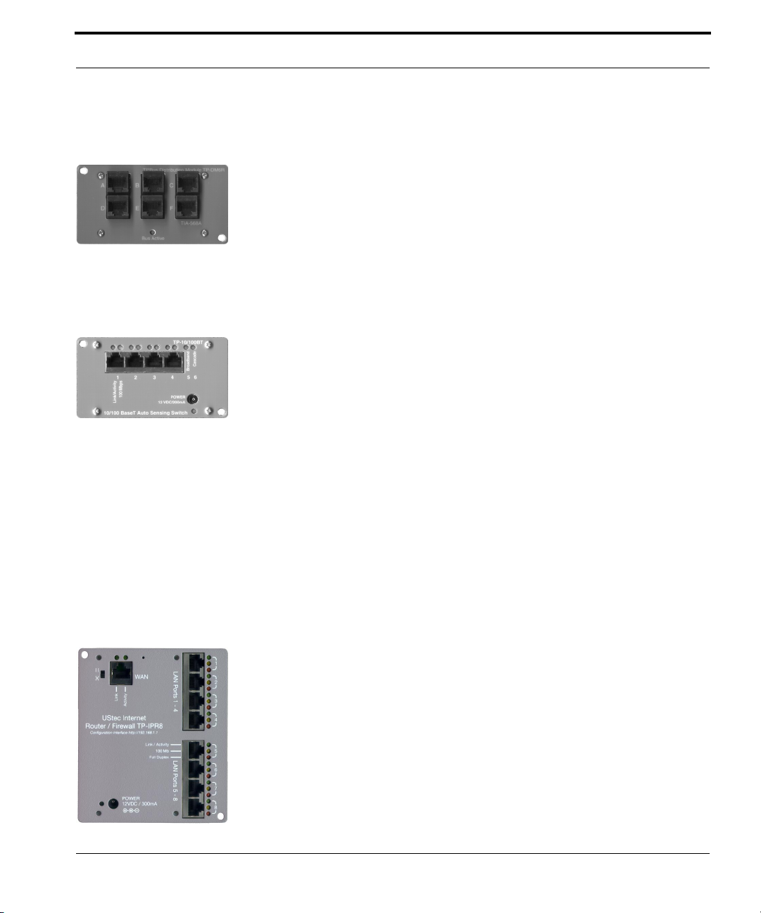
UStec Modules
TP Module TP-DM6R
The TP-DM6R module has been discontinued but is shown here for reference.
The TP-DM6R module provides telephone distribution to six rooms. When
connected to the TP-IN4 module, these units distribute up to four telephone
lines to six different locations. It is possible to distribute six KSU extensions
to six locations in the home with the TP-KSU6R14 adapter cable, however the
TP-KSU8 module and adapter cables replace the TP-DM6R/-KSU6R14 in new
installations.
Computer 10/100BaseT Switch Module TP-10/100BT
The TP-10/100BT Ethernet Switch replaces the TP-10BT Ethernet Hub.
The TP-10/100BT is an auto sensing switch that allows direct port to port
communication on the network. The advantage of direct communication
between ports is faster overall network speed.
For example, connecting a cable modem to a 10/100 hub would limit the
entire hub to run at only 10Mbps. A 10/100 switch on the other hand would
run at 10Mbps on the connected port, while all the others can run at either 10
or 100 Mbps.
The TP-10/100BT is a 6 port switch. Besides the four ports on the front, it has
two cascade ports on the rear circuit board to allow the unit to cascade to
another 10/100 Switch as well as providing a port for broadband access or
other device.
Computer 10/100 Ethernet Switched Router Module TP-IPR8
The TP-IPR8 is an 8 port switched router that is designed to share a high
speed broadband connection for all the computers in the home. The unit also
provides firewall security through network address translation.
The TP-IPR8 can connect 8 computers directly, but has the capacity to connect up to 253 computers. All 8 LAN ports have the “Auto-MDX” feature
which automatically corrects for straight-through/cross-over miswires. Simply
plug in your networked device and go. The WAN port has a manual switch to
accomplish the same feature.
UStec Structured Wiring User Manual
89
Page 90
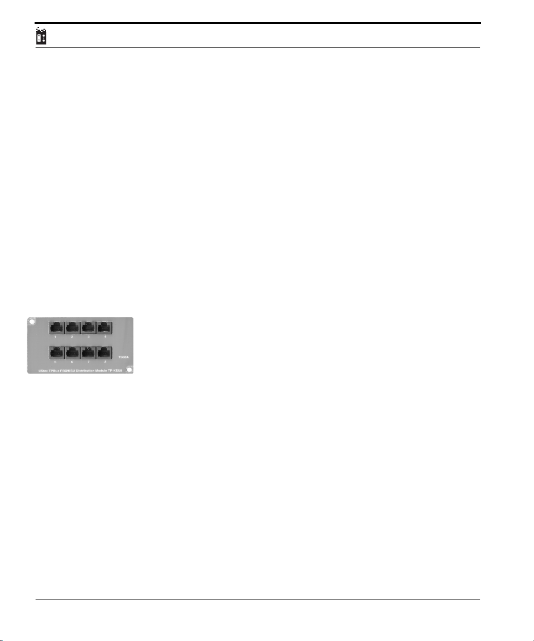
Network address translation allows your computers to be “hidden” from the
Internet, so prying eyes can not see them, only the router. The TP-IPR8 is fully
standards based and can be used with such advanced technologies as VPN
and pass through IPSEC
The configurations to the device are embedded in a web interface. The default
address for connection is http://192.168.1.1. The user name is admin and the
password is admin. Please change the password for security reasons.
The TP-IPR8 comes pre-programmed for many common applications so
setup of some more advanced features is a breeze. The software on the router
is fully upgradeable, so as new features and technologies become available
the unit can be updated.
Unlike the TP-10/100BT, all of the ports on the TP-IPR8 are on the front. In
order to expand pass the initial 8 LAN ports, one LAN port must be used for
cascading to another switch.
Telephone Integration Module TP-KSU8
The TP-KSU8 module is designed to take advantage of today’s key system
units. When used with either the TP-KSU624 or TP-KSU1232 interface cable,
it offers a simple solution to integrating digital phone systems into the structured wiring environment.
90
The TP-KSU8 has 8 RJ45 jacks on its front panel. Each jack connects to the
phone port of a tecPort where a system phone is to be located.
There are 3 connectors on the rear of the TP-KSU8. The 50 pin header receives
the TP-KSU624/TP-KSU1232 adapter cable.
The 24 pin header receives the FX-RIB24 ribbon cable carrying CO lines 3&4
from a TP-IN4RS telephone input module for jacks 1-6. The 10 pin header
allows access to pairs 3&4 in jacks 7-8.
The TP-KSU624 adapter cable carries the digital dial tone from the KSU
switch back to the TP-KSU8 module.
It has 8 RJ14 plugs at one end for connection to the extension outputs on the
KSU, and a 50 pin connector for the KSU8.
UStec Structured Wiring Users Manual
Page 91
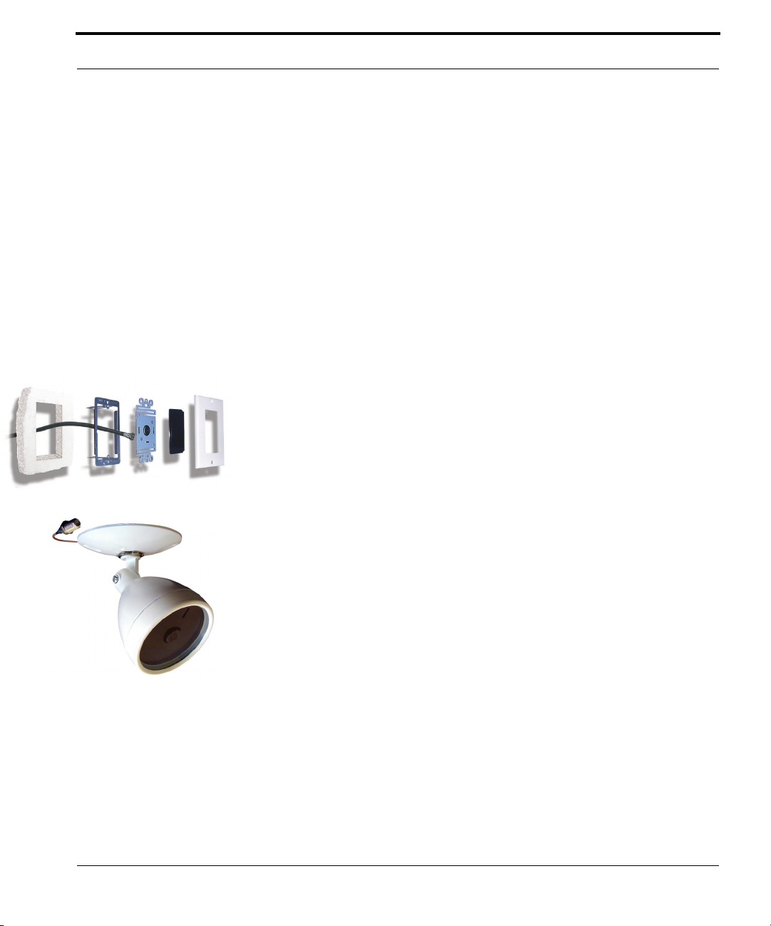
UStec Modules
The TP-KSU624 is used for integration of KSU’s with RJ14 extension outputs,
such as the Panasonic KXT624 and the DSC Communique.
The TP-KSU1232 works the same as the TP–KSU624, but has a standard
pinout Amphenol connector instead of RJ14 plugs.
It is used for integration of KSU’s with Amphenol extension outputs, such as
the Panasonic KXT1232 and KXT 816 (outputs 9-16). Detailed pin-out assignments are available at the UStec website. http://www.ustecnet.com
Surveillance Cameras (CMA-OBW, CMA-OC, CMA-IBW, CMA-IC)
UStec carries both indoor and outdoor surveillance cameras.
The available models include:
Outdoor Cameras: CMA-OBW and CMA-OC with audio (B/W and Color)
Indoor Cameras: CMA-IBW and CMA-IC (currently no audio due to federal
law)
Cameras have built-in modulators and a high output signal level (35 dB).
Power must be supplied by the CX-CM4 module.
The indoor camera fits inside a standard “J” Box.
The outdoor cameras have a weather resistant enclosure.
Camera Setup:
Both the J-box style and outdoor versions of the camera-modulators are connected to the system by a single RG6 coax cable. These cameras are powered
over the coax by the CX-CM4 camera module. Each camera has a built in
modulator which is set using a bank of dip switches located on the camera
circuit board housing.
UStec Structured Wiring User Manual
91
Page 92
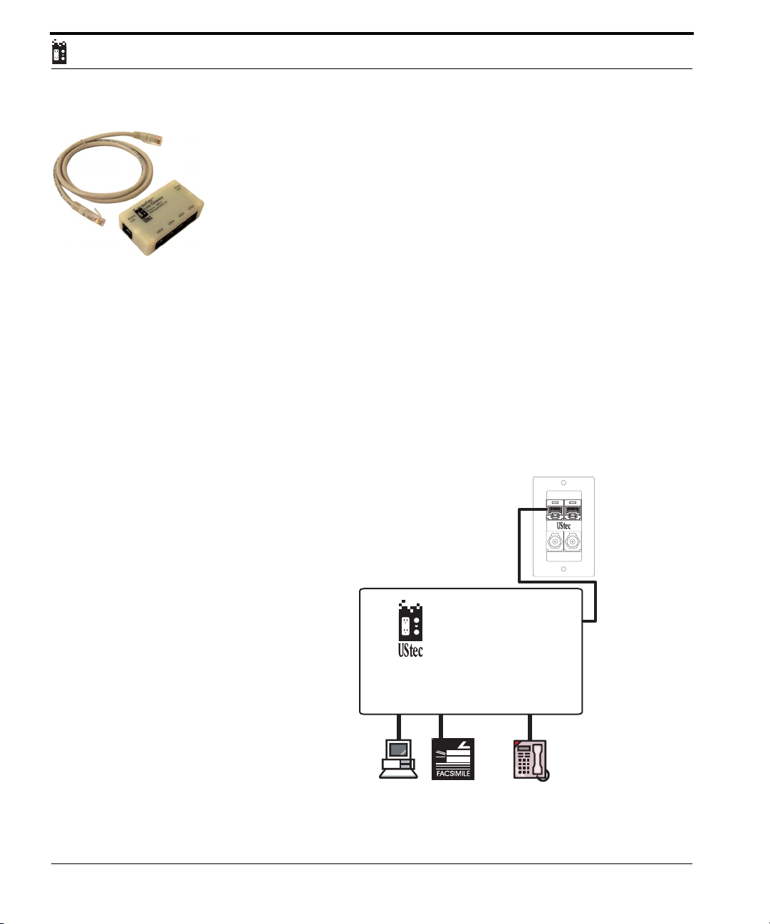
RJ45 Universal Breakout Box UB4.5 (tecFlex Line Chooser)
The RJ45 universal break out box allows you to easily access any phone line
in the system. It is designed to support a structured wiring approach and
eliminates the need for special purpose patch cords. The high quality design
prevents cross-talk.
Up to four telephone lines enter the tecFlex Line Chooser from the wall plate
to the port labeled Phone Line In. The four telephone lines are split apart so
that ordinary single or dual line telephones can access any lines you require.
For a small office home office equipped with dual-line phone, fax, modem
and these incoming lines: Line1 – House, Line2 – Business, Line3 – Fax,
Line4 – Modem
Connect the two-line telephone to jack L2/1. This makes business line 2 the
primary line.
Connect the fax machine to L3/4
Connect the modem to L4/3.
DataTVPhone
92
L4/L3
tecFlex
Line Chooser
Module - UB4.5
www.ustecnet.com
L3/L4 L2/L1 L1/L2
Phone
Line
UStec Structured Wiring Users Manual
Internal
TM
Phone
Line
Page 93

UStec Basic Troubleshooting.
UStec Basic Troubleshooting.
This documentation is designed to help you with issues that might arise over
the course of use with a UStec system. These suggestions are not a replacement to the expertise that your dealer has. Many times third party products
are integrated into a UStec system and may make the suggestions here inadequate.
In all cases make certain there is power to the UStec system.
Please contact your dealer if your issue can not be resolved here.
Telecom Issues
No telephone service
If anything new was just added, disconnect it and check for dial tone
Check another telephone to make certain the telephone is not dead
Disconnect service feed from unit (port will say Telco In) wait a two minutes
and reconnect. If service returns and then goes away call dealer. Could be bad
telephone or ongoing surge condition.
Connect a telephone directly to the incoming line from the NID, If you have
dial tone call your UStec dealer. If you do not have dial tone call the telephone company.
No Cable Television or Off-Air Signals
On un-amplified systems such as CX-4X4U, CX-4X4U.1, and tecReady series
call the cable company.
On all systems with an amplifier (assumes it worked fine before issue) check
to make certain you have power to the unit.
Direct connect a TV to the incoming service. If it is acceptable, call your
dealer, otherwise call the service provider.
UStec Structured Wiring User Manual
93
Page 94

Ethernet Connection Issues
Can not communicate with other computers. (On the TP-IPR8 see its own
manual)
Make certain all computers have network cards, and that they are plugged
into the Data port on the tecPort which in turn is connected to the Ethernet switch or router in your UStec panel.
Make certain you have link lights on all connected equipment.
Check computers to make certain they are on the same network. Do this
by typing at a command prompt in Windows ipconfig /all
All computers should have the same ip address range and subnetmask
such as 192.168.1.x where x is a number from 1 to 254 and the subnet is
the same such as 255.255.255.0. If they are different correct this.
Reset the Ethernet switches by turning off the power for one minute and
re-powering.
Call UStec dealer.
Advanced troubleshooting documentation is available on the website in the
technical support section. Please also read any documentation that may have
accompanied the product in question.
94
UStec Structured Wiring Users Manual
Page 95

UStec 15-Year Performance Guarantee
UStec 15-Year Performance Guarantee
UStec provides the homeowner with a 15-Year Performance Guarantee for the
cabling and connectors of the tecLAN network. This warranty covers only
jacketed tecWire with enhanced Cat5 cable.
The UStec tecWire and UStec connectors/jacks are guaranteed to meet minimum Category 5 bandwidth/crosstalk requirements as specified by TIA/EIA
Standards and minimum coaxial cable shielding performance requirements
as specified by the CATV industry.
To qualify, the cabling must be installed and tested by a registered, certified
UStec dealer installer. All network components must be purchased from
UStec. Dealers must submit to UStec a completed registration form for each
installation to be covered by the warranty.
UStec will be responsible for correcting any defective runs, including labor
and materials. It will be the dealer’s responsibility to cover any connector
mis-wire installation defects. Provisions shall not cover any ‘Acts of Nature’ or
physical on-site damage to components.
This 15-Year Performance Guarantee is owner transferable.
UStec Structured Wiring User Manual
95
Page 96

96
UStec Structured Wiring Users Manual
Page 97

A
Amphenol 91
AU-2X4 75, 87
Audio Distribution 75
C
CMA-IBW 91
CMA-IC 91
CMA-OBW 91
CMA-OC 91
Computer Networking 69
CX-4X4U 84
CX-4X4U.1 84
CX-AMP16 83
CX-AMP8 83
CX-CM4 71 , 86
CX-DM8 84
CX-DSS4 85
CX-DSS58 85
CX-HDA58 86
E
Ethernet 89
F
Firewall 89
G
Glossary 9
I
iLAN 1600 44
iLAN 400 24
iLAN 800 28
iLAN 800 – GS 29
iLAN MDU 20
Infrared Remote Controls 73
IntelliWAY 30
IntelliWAY Gateway Server 49
IP cameras 79
IR-KIT 73
iSAT 1600 47
iSAT 800 34
iSAT 850 38
K
Key System Unit 90
KSU 90
M
MDU series 19
MOD1CH 61
Modulation and distributing
video 61
Modules 81
MP3 Player 79
N
No Cable Television or Off-Air 93
O
One Way satellite 67
R
RJ31X 88
RJ45 92
Router 89
S
Satellite Internet Hookup 65
Satellite Multiswitch 85
Satellite Television Hookup 55
Server Modules 81
Surge (telephone) 88
Surge Coax 83, 84
Surveillance Cameras 71 , 91
System Topology 15
T
tecFlex Line Chooser 92
tecLAN 1600 43
tecLAN 1600 Basic 42
tecLAN 400 24
tecLAN 400 Basic 23
tecLAN 800 28
tecLAN 800 Basic 27
tecLAN MDU 20
tecLAN MDU Basic 19
tecReady 1600 41
tecReady 400 23
UStec Structured Wiring User Manual
1
Page 98

tecReady 800 27
tecReady MDU222 19
tecSAT 1600 46
tecSAT 800 34
tecSat 800 Basic 33
tecSat 850 37
Telecom Issues 93
Third Party equipment 79
TP-10/100BT 89
TP-DM10R 88
TP-DM6R 89
TP-IN4RS 88
TP-IPR8 89
TP-KSU1232 90
TP-KSU624 90
TP-KSU8 90
Two-Way Satellite 65
U
Universal Breakout Box 92
UStec Basic Troubleshooting 93
UStec Modules 81
UX-DC6.1 87
W
Warranty 95
2
UStec Structured Wiring User Manual
Page 99
 Loading...