

Page 1

i
This manual covers installation and operating instructions for the following U.S. Robotics modems:
Sportster® 56 kbps∗ Winmodem™
U.S. Robotics, the USRobotics logo, V.Everything, Winmodem, and Sportster are registered
trademarks and Connections, Total Control, Courier, RapidComm, x2, and the x2 logo are
trademarks of 3Com Corporation or its subsidiaries. Windows and Internet Explorer are registered
trademarks of Microsoft Corp. CompuServe is a registered trademark of CompuServe Inc. America
Online is a registered trademark of America Online Inc. Netscape Navigator is a trademark of
Netscape Communications Corp. Any other trademarks, trade names, or service marks used in this
manual are the property of their respective owners.
© 1997 3Com Corporation or its subsidiaries
7770 North Frontage Road
Skokie, IL 60077-2690
All Rights Reserved
∗∗ IMPORTANT! All x2 products are capable of 56 kbps downloads; however, due to FCC rules
which restrict power output of the service providers' modems, current download speeds are limited to
53 kbps. Actual speeds may vary depending on line conditions. Uploads from users to service
providers travel at speeds up to 33.6 kbps. An x2-capable modem, an x2-compatible analog phone
line and an x2-capable Internet Service Provider are necessary for these high-speed downloads.
Page 2

TABLE OF CONTENTS
Welcome to x2™ Information Access 1
Product Features 3
Windows 95 Hardware Installation 4
Checking Your Version of Windows 95 5
How to Insert the Modem 6
How to Move Through the “New Hardware Found” Screens in Windows 950 or 950a10
Installing the Winmodem Software Under Windows 950b 12
Uninstalling the Winmodem Software in Windows 95 16
Windows 3.x Hardware Installation 19
How to Insert the Modem 20
Running the Installation Program on a Windows 3.1 or 3.11 System 23
Software Installation and Testing 29
Software Installation and Registration using the Setup Wizard 29
Sending Your First Fax 44
Using Other Communications Software 47
Page 3

TABLE OF CONTENTS
iii
U.S. Robotics Modem Update Wizard 49
Installation 50
Operation 54
Troubleshooting and Online Help Resources 62
Online Help Resources 68
Connecting to the 3Com BBS 68
Downloading the Technical Reference Guide 69
World Wide Web 71
CompuServ 71
America Online 71
Fax and Technical Support Hotline 71
RapidComm Trouble Shooting Tips 73
Using Modem Station 75
Installing Modem Station 75
Using Detect New Modems 80
Using Terminal 82
Using Modem Configurator 84
Using Modem to Computer 87
Page 4

TABLE OF CONTENTS
iv
The Extended Information Screens 92
Glossary 93
Technical Quick Reference 107
Command Summary 108
S-Registers 123
Regulatory Information 134
Fax Branding 136
For Canadian Modem Users 138
Limited Warranty 142
Index 144
Page 5

WELCOME TO x2 TECHNOLOGY INFORMATION ACCESS
1
The latest breakthrough in
online communications
Until now, 33.6 kbps was thought to be the
practical limit for speed over standard phone
lines. Now, x2 Technology shatters that
barrier, to bring you high speed downloads. x2
Technology is capable of 56kbps downloads,
but, due to FCC rules which restrict power
output of your service provider’s modems,
current download speeds are limited to 53
kbps. This modem is software upgradable,
allowing easy upgrades to new features and
enhancements as they become available.
An integrated end-to-end
solution from the leader
3Com is well positioned to bring you x2
Technology. Our U.S. Robotics Sportster
®
modems are the world's number one seller,
and our Total ControlTM and CourierTM product
lines are favored by many Internet service
providers. This widespread acceptance allows
3Com to offer x2 Technology to virtually
anyone.
Page 6

WELCOME TO X2 INFORMATION ACCESS
2
Taking advantage of the
modern telephone network
x2 Technology takes advantage of the typical
network configuration found when an analog
subscriber connects to a digitally connected
server. x2 can use nearly all of the available
64K network bandwidth. (Upstream data,
typically less speed sensitive, travels at the
standard V.34 rate.)
The result is a completely new kind of
transmission technique. Based on “encoding”
rather than “modulation,” it can give you
download speeds that you never thought
possible. What’s more, with standard V.42 bis
compression, x2 can download at speeds up
to a blistering 115.2 kbps.
Updating x 2 technology is
easy and FREE!
Read the section of this manual titled “U.S.
Robotics Modem Update Wizard” (page 41)
for information about using this software (on
the Connections™ CD) to update your
modem’s code to the latest version.
The new standard for online
speed
3Com has already submitted x2 to the ITU-T
standards committee for acceptance as the
next online standard. For more information on
U.S. Robotics’ x2 technology, see our World
Wide Web page at http://x2.usr.com.
Page 7

PRODUCT FEATURES
3
Your new x2 modem
provides many advanced
features. Here are just a
few:
Modulation Schemes
x2 technology
ITU-T V.34+
ITU-T V.34
ITU-T V.32bis
ITU-T V.32
ITU-T V.22bis
ITU-T V.22
ITU-T V.23
Bell 212A
ITU-T V.21
Bell 103
Error Control and Data
Compression Schemes
ITU-T V.42
ITU-T V.42bis
MNP 2-5
Fax Modulation
Schemes
ITU-T V.17
ITU-T V.29
ITU-T V.27ter
ITU-T V.21
Fax Standards
EIA 578 Class 1 FAX
EIA 592 Class 2.0 FAX
Front Channel Link
Rates
33333, 37333, 41333, 42666,
44000, 45333, 46666, 48000,
49333, 50666, 52000, 53333,
54666, 56000, 57333
Back Channel Link
Rates
4800, 7200, 9600, 12000, 14400,
16800, 19200, 21600, 24000,
26400, 28800, 31200
V.34+ Link Rates
4800, 7200, 9600, 12000, 14400,
16800, 19200, 21600, 24000,
26400, 28800, 31200, 33600
V.32bis Link Rates
4800, 7200, 9600, 12000, 14400
Additional Link Rates
300, 1200/75 (V.23), 1200, 2400
Fax Link Rates
2400, 4800, 7200, 9600, 12000,
14400
Page 8

WINDOWS 95 HARDWARE INSTALLATION
4
You’ll need these items from your
Sportster modem box:
the modem a phone cord
the Connections CD this manual
Winmodem disk Installation
Guide
Plus: a screwdriver (not included)
NOTE! These instructions are for
Windows 95 users. If your computer is
running Windows 3.x, please refer to
the online documentation included on
the Connections CD-ROM. The software
installation instructions in the
“Software Installation and Testing”
section of this manual apply to both
Windows 95 and Windows 3.x users.
Page 9

WINMODEM HARDWARE INSTALLATION
5
Windows 95 Users
To install your Winmodem properly, you must
first know which version of Windows 95 you
have. Please follow these instructions to check.
Checking Your Version of
Windows 95
1. Start Windows
Right-click the My Computer icon.
2. Select Properties.
3. Find your version number in the upper right
corner of the “General” screen below.
In the example preceding, the version is 950a.
Page 10

WINMODEM HARDWARE INSTALLATION
6
Make a note of the Windows version you are
using. You will follow different instructions for
navigating the “New Hardware Found”
screens depending on which version of
Windows you are using.
How to Insert the Modem
NOTE: Before installing your
modem, write down the modem's
serial number in the manual. (The
serial number is on the bar coded
sticker on the modem and on the
outside of the box the modem came
in.) If you ever need to call our
technical support department, the
technical support representative will
ask you for the serial number. This
will help him or her identify the type
of modem you have.
1. Turn off your computer and unplug it from
the electrical outlet.
2. Unplug any peripheral devices (printer,
monitor, keyboard, mouse, etc.) from the
computer.
TIP: If you haven’t added
accessories to your computer before, we
suggest labeling the cords and cables
before unplugging them.
CAUTION: To avoid being
shocked, make sure your computer and
all peripheral devices are turned off and
unplugged from the electrical outlets.
Page 11

WINMODEM HARDWARE INSTALLATION
7
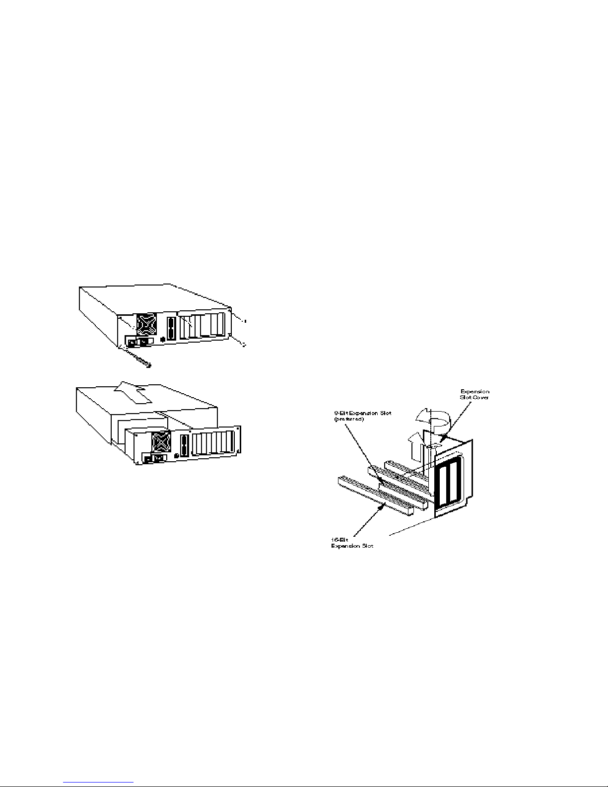
3. Remove the screws from your computer’s
cover and then remove the cover. Your
computer may look different from this
drawing, but the basic principle for
removing the cover should be the same.
Refer to your computer manufacturer’s
manual if you need further instructions.
4. Find an empty ISA expansion slot that’s at
least as long as the gold edge of your
modem. (ISA slots are black plastic
grooves lined with metal.) Unscrew and
remove the expansion slot cover (the long
narrow piece of metal that keeps dust from
entering through the opening that’s
perpendicular to the slot).
Page 12

WINMODEM HARDWARE INSTALLATION
8
Holding the modem by each corner, align
the gold edge with an empty expansion slot.
Push down gently until the modem snaps
into the slot. (Note: The drawing shows
horizontally aligned expansion slots. Some
computers have vertically aligned slots. The
instructions apply to both styles.)
You’ll have to apply a little pressure to seat
the modem properly. Sometimes a gentle
back-and-forth motion helps get the
modem all the way into the slot. If you feel
resistance, the modem may not be properly
lined up with the slot. Do not force it. Take
the modem all the way out and try again.
5. Once the modem is seated, secure it using
the screw you removed in step 4.
6. Put the computer’s cover back on and
replace the screws.
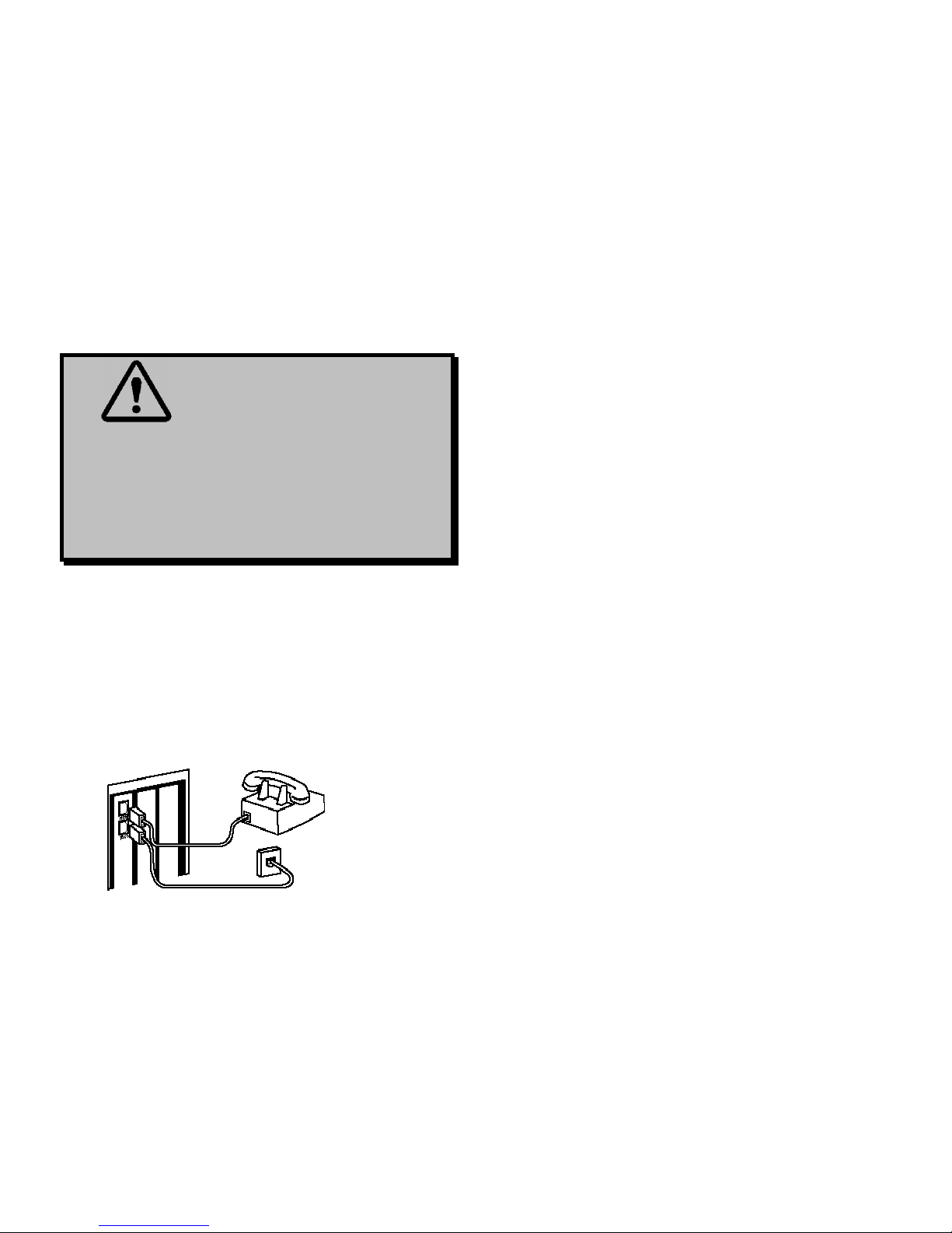
7. If you currently have a phone plugged into
the wall jack you’re going to use for the
modem, disconnect the phone’s cable from
the jack.
8. Plug one end of the phone cable that came
with the modem into the TELCO jack at
the rear of the modem.
Page 13

WINMODEM HARDWARE INSTALLATION
9
WARNING: Be certain you
are plugging the phone line into an
ANALOG jack. Many office phones
use DIGITAL lines. Attaching your
modem to a digital line will damage
the modem!
9. Plug the other end of the cable into the wall
jack.
10. (If you want to use a telephone on the
same line as the modem, plug the
telephone’s cable into the modem’s
PHONE jack.)
11. Plug the power cords, cables, and
peripherals back into the computer and
turn the computer on.
Page 14
WINMODEM HARDWARE INSTALLATION
10
How to Move Through the
“New Hardware Found ”
Screens in Windows 950 or
950a.
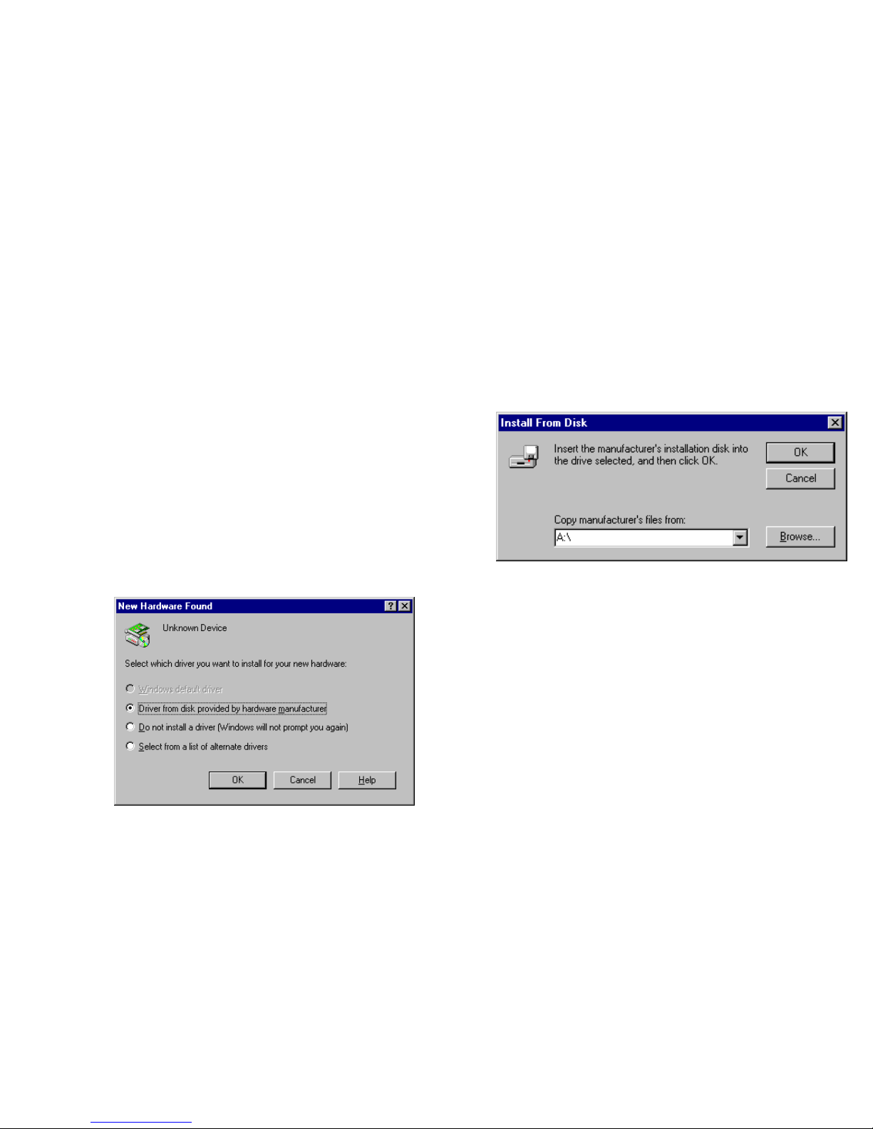
1. This screen will come up when
Windows restarts. If the Driver from
disk… option is not already selected,
select it now. Click Next to continue.
2. When you see this screen, insert the
Winmodem floppy disk and Click OK.
3. You will see a screen confirming that you
are installing a Winmodem. When that
finishes, remove the Winmodem disk. The
following screen tells you which
communications port your Winmodem has
been installed to.
Page 15

WINMODEM HARDWARE INSTALLATION
11
Make a note of the COM port and then
click OK. You may need this information
when installing communications software.
4. Windows will now restart. Click Yes on
this screen to restart Windows.
5. When Windows restarts, check to see if
the Winmodem is correctly installed. Click
Start and point to Settings. Click
Control Panel. You should see a new
Winmodem icon like the one pictured
below. Turn to the section entitled
‘Software Installation and Testing” (page
21) to begin installing your RapidComm
communications software.
Page 16

WINMODEM HARDWARE INSTALLATION
12
NOTE: If you did not see a
Winmodem icon or the screen
directly preceding, or if you instead
got a message that files are
corrupt—turn to the section
entitled: “Uninstalling the
Winmodem Software”.
Installing the Winmodem
software under Windows
950b.
The procedure for installing your Winmodem
software is slightly different under Windows
950b. Please follow these instructions to install
your software.
1. When you see this screen after Windows
starts,
DO NOT click anything
DO NOT press ENTER.
Instead, insert your Winmodem disk in
your floppy drive. (Once you’ve installed
the Winmodem software, the modem will
be correctly identified.)
Page 17

WINMODEM HARDWARE INSTALLATION
13
2. Click Next on this screen to continue.
3. When you see this screen, click Finish.
NOTE: If you see the screen below instead of
the screen preceding, click the Back button.
4. When you see this screen, click the OK
button:
Page 18

WINMODEM HARDWARE INSTALLATION
14
5. When you see this screen, type A:\. (Be
sure to type the period after the
backslash.) to replace whatever is in the
Copy files from box.
Then click OK..
6. You will see a series of screens as files
copy and drivers build.
7. Finally, you will see a screen telling you
that the modem has been installed. This
screen will also show the COM port
assignment for the modem. Click OK.
8. Windows will now restart.
9. Once Windows restarts, check the
installation by going into the Control
Panel.
Page 19

WINMODEM HARDWARE INSTALLATION
15
10. Click the Winmodem icon:
11. You should then see this screen: Click
OK.
NOTE: If you did not see a
Winmodem icon or the screen
directly above—if you instead got a
message that files are corrupt—turn
to the section entitled: “ReInstalling the Winmodem Software”.
12. For instructions on how to install the
RapidComm fax/data software, go to the
section entitled “Software Installation and
Testing” (page 21).
Page 20

WINMODEM HARDWARE INSTALLATION
16
Uninstalling the Winmodem
Software in Windows 95.
From the Start Menu, point to Settings and
then click Control Panel. Click the
Winmodem icon and then select Uninstall.
Follow the onscreen prompts.
After running the uninstall, please follow these
steps to insure that the Winmodem software
has been completely removed from your
system.
1. Restart Windows.
2. Insert the Winmodem disk that came with
your new modem into your floppy drive.
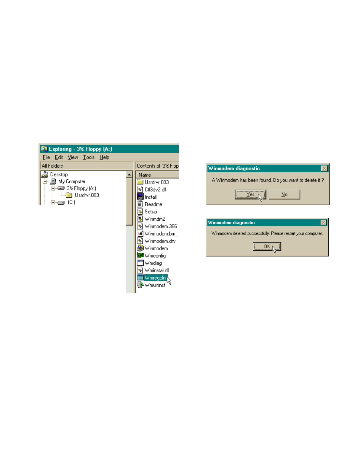
3. Start the Windows Explorer program.
4. Click the icon for your floppy drive.
Page 21
WINMODEM HARDWARE INSTALLATION
17
5. Double-click the Wmregcln file.
6. If the uninstall program completely
removed the Winmodem software from
your system, you will see a screen saying
that “No Winmodem was found.”
Otherwise, when you see this screen, click
Yes.
7. When you see this screen, click OK.
8. Shut down your computer.
9. Start Windows.
10. If you are uninstalling your Winmodem
Software due to a failed installation, please
proceed to the section entitled “Installing
the Winmodem Software under Windows
950 or 950A” (page 11), or the section
entitled “Installing the Winmodem
Software under Windows 950b” (page
Page 22

WINMODEM HARDWARE INSTALLATION
18
13). If you are not sure which version of
Windows 95 you are using, please refer to the
section entitled “Checking your Windows
Version” (page 6).
These instructions cover the installation of the
Winmodem hardware and the accompanying
software under Windows 3.x. These
instructions are for users of either Windows
3.1, Windows 3.11, or Windows for
Workgroups
Page 23

WINDOWS 3.X HARDWARE INSTALLATION
19
You’ll need these items from your
Sportster modem box:
the modem a phone
cord the Connections CD this
manual
Winmodem disk Installation
Guide
Plus: a screwdriver (not included)
This chapter will walk you through the
installation of your Winmodem. There are two
parts to the installation: hardware (the modem)
and software. The modem must be installed
before the software.
Plug and Play:
Your Winmodem supports Plug and Play
installation, the fastest, easiest way to
add new features (a modem, a sound
card, etc.) to your PC.
Page 24

WINMODEM INSTALLATION UNDER WINDOWS 3.X
20
How to Insert the Modem
NOTE: Before installing your
modem, write down the modem's
serial number in the manual. (The
serial number is on the bar coded
sticker on the modem and on the
outside of the box the modem came
in.) If you ever need to call our
technical support department, the
technical support representative will
ask you for the serial number. This
will help him or her identify the type
of modem you have.
1. Turn off your computer and unplug it from
the electrical outlet.
2. Unplug any peripheral devices (printer,
monitor, keyboard, mouse, etc.) from the
computer.
TIP: If you haven’t added
accessories to your computer before, we
suggest labeling the cords and cables
before unplugging them.
CAUTION: To avoid being
shocked, make sure your computer and
all peripheral devices are turned off and
unplugged from the electrical outlets.
3. Remove the screws from your computer’s
cover and then remove the cover. Your
computer may look different from this
drawing, but the basic principle for
Page 25
WINMODEM INSTALLATION UNDER WINDOWS 3.X
21
removing the cover should be the same.
Refer to your computer manufacturer’s
manual if you need further instructions.
4. Find an empty ISA expansion slot that’s at
least as long as the gold edge of your
modem. (ISA slots are black plastic
grooves lined with metal.) Unscrew and
remove the expansion slot cover (the long
narrow piece of metal that keeps dust from
entering through the opening that’s
perpendicular to the slot).
Page 26

WINMODEM INSTALLATION UNDER WINDOWS 3.X
22
Holding the modem by each corner, align
the gold edge with an empty expansion slot.
Push down gently until the modem snaps
into the slot. (Note: The drawing shows
horizontally aligned expansion slots. Some
computers have vertically aligned slots. The
instructions apply to both styles.)
You’ll have to apply a little pressure to seat
the modem properly. Sometimes a gentle
back-and-forth motion helps get the
modem all the way into the slot. If you feel
resistance, the modem may not be properly
lined up with the slot. Do not force it. Take
the modem all the way out and try again.
5. Once the modem is seated, secure it using
the screw you removed in step 4.
6. Put the computer’s cover back on and
replace the screws.
7. If you currently have a phone plugged into
the wall jack you’re going to use for the
modem, disconnect the phone’s cable from
the jack.
8. Plug one end of the phone cable that came
with the modem into the TELCO jack at
the rear of the modem.
Page 27
WINMODEM INSTALLATION UNDER WINDOWS 3.X
23
WARNING: Be certain you
are plugging the phone line into an
ANALOG jack. Many office phones
use DIGITAL lines. Attaching your
modem to a digital line will damage
the modem!
9. Plug the other end of the cable into the wall
jack.
10. (If you want to use a telephone on the
same line as the modem, plug the
telephone’s cable into the modem’s
PHONE jack.)
11. Plug the power cords, cables, and
peripherals back into the computer and
turn the computer on.
12. If Windows does not start automatically,
please start it now.
Modem Initialization
Your Winmodem came with a diskette that
contains an installation program that will help
your computer finish installing the modem. The
installation program will also copy modem
programs from the disk onto your computer’s
hard drive.
Running the Installation Program
on a Windows 3.1 or 3.11 System
After inserting the Winmodem follow these
steps:
Page 28

WINMODEM INSTALLATION UNDER WINDOWS 3.X
24
1. Insert the installation diskette.
Click File and select Run. In the
Command Line text box, type
a:\install.exe. Click OK.
2. The next screen will tell you where the
Winmodem installation files will be located.
Click Continue to copy the Winmodem
files to this directory. If you wish to copy
the Winmodem files to a different
directory, type the path to that directory
here.
3. This screen tells you that the software will
create the new Winmodem directory.
Click Yes.
Page 29

WINMODEM INSTALLATION UNDER WINDOWS 3.X
25
4. The following screen lets you know the
installation software is being loaded to your
hard drive. Let it finish.
5. This next screen tells you that modifications
have been made to your Windows system
files. Click OK.
6. This next screen tells you that the software
will automatically detect available
communications ports for the Winmodem.
Click OK.
Page 30

WINMODEM INSTALLATION UNDER WINDOWS 3.X
26
7. After the software detects the available
COM ports, it will ask you select one for
the Winmodem. Highlight any free one
and then click OK. See the
troubleshooting section if the software
does not locate an available COM port.
8. Congratulations, your Winmodem
software has been installed. Click
Restart Windows to finish the
process.
9. Windows will now restart. At this point,
you will see a new Winmodem group like
Page 31

WINMODEM INSTALLATION UNDER WINDOWS 3.X
27
the one shown below.
(Note: if you do not see a new
Winmodem group, you will instead see the
Configuration screen. You will have to
choose an available I/O address and an
available IRQ. Do not select Let plug and
play configure…)
• For the I/O address: Choose any on the list.
• For the IRQ: The COM port/IRQ
combinations shown here work with most
computer set-ups:
COM IRQ
1....................4
2....................3
3....................5, 7, or 9
4....................5, 7, or 9
If you have a sound card, SCSI card,
or game card, it might be using IRQ 5
or 7. Do not make 5 or 7 your first
choice then, because it might not be
available.
Page 32

WINMODEM INSTALLATION UNDER WINDOWS 3.X
28
Once you’ve chosen a combination,
restart Windows. You should see the
Winmodem group. If you do not see
this group, try a different combination of
resources.
• If you chose an unavailable I/O
address, you will get an error
message. Choose another I/O
address in the Configuration
dialog box that appears.
• If you chose an unavailable IRQ,
you may encounter problems when
your communications software
program tells you it cannot find the
modem. At that point choose
another IRQ in the Configuration
dialog box. (You can find it by
clicking on the Configurator icon in
the Winmodem group in the
Program Manager window.)
Once you’ve finished installing your modem,
you are ready to install the RapidComm
communications software. Please turn to the
section entitled “Software Installation and
Testing”(page 33).
Page 33

SOFTWARE INSTALLATION AND TESTING
29
Software Installation and Registration
Using the Setup Wizard
This section guides you through the U.S.
Robotics Setup Wizard, the
Connections CD-ROM interface, and the
installation of RapidComm (fax/data software).
It also shows you how to register and test your
new Sportster modem.
RapidComm fax/data software simplifies
sending and receiving faxes directly from your
computer desktop. You can build your own
fax directory, send faxes to specified groups of
phone numbers, request individual cover pages
when necessary, and send individual faxes
without exiting your word processing program.
Additionally, RapidComm lets you connect to
BBSs and other online data providers. Take
advantage of this access to enter a new world
of information and entertainment.
NOTE: The following instructions
apply to Windows 3.x and Windows 95
users. However, only Windows 95
screens are shown.
NOTE: If you have an older
version of RapidComm installed on your
system, you must uninstall it before
continuing.
Page 34

SOFTWARE INSTALLATION AND TESTING
30
1. From the Windows 95 desktop, click
Start and select Run.
2. In the Run text box, type D:\setup.exe.
(If your CD-ROM drive has a letter name
other than D, type that letter in place of
D.) Click OK.
3. You will briefly see a screen that looks like
this.
4. When you are asked if you wish to run the
Setup Wizard, click Yes.
Page 35

SOFTWARE INSTALLATION AND TESTING
31
5. This is the introduction to the Setup
Wizard. After reading this screen, click
Next.
6. When you see the following screen,
select your modem from the list, verify
that the COM port setting is correct,
and then click Next.
Page 36

SOFTWARE INSTALLATION AND TESTING
32
7. When you see the next two screens, fill in
the blank boxes with the appropriate
information, pressing the TAB key to move
between fields. Click Next on each screen
when you have filled in all of the necessary
information.
8. You will see the following screen as the
Setup Wizard creates a U.S. Robotics
Connections program group.
9. Next, the Setup Wizard looks for
Microsoft’s Internet Explorer on your
system.
If the Setup Wizard does not find Internet
Explorer, it will automatically install the
application later in the Setup Wizard
process.
Page 37

SOFTWARE INSTALLATION AND TESTING
33
10. The next screen introduces the U.S.
Robotics Registration Wizard. After you
read the screen, click Next. Read through
each of the next two screens and verify or
correct the information you typed earlier.
Click Next on each screen to move on.
Page 38

SOFTWARE INSTALLATION AND TESTING
34
11. When you see this screen, you are ready
to register your new Sportster. By
Modem will already be selected. We
recommend you choose the By Modem
option because it’s a great way to verify
that your Sportster is correctly installed.
Choose By Modem by clicking OK.
12. When you see this screen…
• If you need to dial a prefix (such as 9) to
make a call outside your building, type
the prefix before the 1 in the Prefix box
and then click Dial. If the modem still
does not dial the number properly, you
may need to insert a comma between the
prefix and the 1 to force the modem to
pause after dialing the prefix.
Page 39

SOFTWARE INSTALLATION AND TESTING
35
• If you do not need to dial a prefix,
simply click Dial.
13. You will see a screen indicating that the
registration information has been sent (see
the circled text in the screen below).
14. The next screen indicates that the Setup
Wizard is finished. Click OK to launch the
Connections CD-ROM.
NOTE: If the Setup Wizard detected
Internet Explorer on your system during the
setup process, your computer will launch
the Connections CD-ROM when you click
OK. Continue at step 15.
If the Setup Wizard DID NOT detect
Internet Explorer on your system earlier in
the setup process, it will launch the Internet
Explorer installation utility after you click
OK. When you see the following screen,
click Install Internet Explorer and follow
the on-screen instructions to complete the
installation of the software.
Page 40

SOFTWARE INSTALLATION AND TESTING
36
At the end of the installation process, you
will see the following screen. Click Yes.
Windows 95 users: Windows will restart
and the Connections CD will launch
automatically upon restart.
Windows 3.x users: Windows will
restart. When your desktop reappears, you
will see a Connections icon (shown
below) in the Connections program group.
Double-click on this icon to launch the CD.
Page 41

SOFTWARE INSTALLATION AND TESTING
37
15. When the main Connections menu
appears, click Business & Productivity
in the menu on the left hand side of the
screen (circled below).
16. Double-click the RapidComm button on
the Business & Productivity menu
(circled in the following screen shot).
RapidComm is the fax/data software you
can use to send faxes directly from your
desktop, transfer files electronically, or dial
into a BBS.
Page 42

SOFTWARE INSTALLATION AND TESTING
38
17. The next screen contains another menu on
the right hand side of the screen. Click
Learn More & Get Software (circled in
the screen image below).
18. The next screen displays information about
RapidComm. You can use the scroll bar
on the right hand side of the screen to
scroll through the text. When you are
ready to install RapidComm, click Install
(circled in the lower left hand corner of the
following screen image).
Page 43

SOFTWARE INSTALLATION AND TESTING
39
19. The screen shown below is the first of the
RapidComm Setup screens. When this
screen appears, make sure the location
shown in the text box is where you would
like the files copied to and then click
Install. If you wish to copy the
RapidComm files to a different directory,
type that location in the text box before
clicking on Install.
20. You will see this screen as files are copied.
21. When you see this screen, click on either
Yes or No.
• If you click Yes, every document you
print will be treated as a fax unless you
change the printer selection in the
program from which you are printing.
• If you click No, RapidComm will not be
selected as the default printer. When you
Page 44

SOFTWARE INSTALLATION AND TESTING
40
want to send a fax, you must select
RapidComm as the printer in the
program from which you are printing.
22. This screen marks the end of the
RapidComm installation. Click OK
23. Clicking OK returns you to the
Connections interface. Click Exit (circled
in the following screen image).
Page 45

SOFTWARE INSTALLATION AND TESTING
41
24. Restart Windows by selecting the Restart
the Computer? option from the Shut
Down menu in the Windows Start menu.
25. When your desktop appears, launch
RapidComm from the Windows Start
menu.
26. The following screen is the first screen of
the RapidComm Setup Wizard. After you
read the screen, click Next.
Page 46

SOFTWARE INSTALLATION AND TESTING
42
27. When you see this screen, verify the
information shown and then fill in the Data
box (if you have a third phone number just
for your modem) and the Local Area
Code box. Then click Next.
28. After you verify the information on this
screen, click Next.
Page 47

SOFTWARE INSTALLATION AND TESTING
43
29. Select the correct modem in the text box
on the following screen. Then click Next.
30. When you see this screen…
• If you want RapidComm to launch with
every Windows startup, click on the box
to the left of Run RapidComm at
Windows startup. A check will appear
in the box. Then click Finish.
• If you do not want RapidComm to start
every time you start Windows, simply
click Finish.
Page 48

SOFTWARE INSTALLATION AND TESTING
44
31. You will see this screen.
This is the main RapidComm screen. To
send your first fax, keep this screen open.
(After this initial run, RapidComm will not
need to be running in order to send a fax.)
Sending Your First Fax
Using RapidComm, you can send and receive
faxes directly from your computer and
eliminate the need for an expensive fax
machine. Once you learn the basics of sending
faxes, you can learn more involved fax
functions, such as sending documents to
groups of numbers at assigned times and how
to transfer data files. These more advanced
functions are explained in the electronic
RapidComm manual on your Connections
CD. This chapter will walk you through
sending your first fax.
1. Open an application in which you can
create documents that you might want to
fax (e.g., a word processing application).
Create a document containing only a
sentence or two. Name the document
“tester”. Keep the document open.
Page 49

SOFTWARE INSTALLATION AND TESTING
45
2. From the File menu, select Print.
3. Select RapidComm as the printer. This can
be changed in most Windows applications
in the Print dialog box.
4. Click OK or Print (whichever button you
click in your application to indicate that
you are ready to print) in the Print dialog
box.
5. When you see the following screen, fill in
the necessary information in the text boxes.
For testing purposes, send your “tester”
document to the U.S. Robotics fax
number, 847-676-3559.
NOTE: If you need to enter a
prefix (such as 9) to dial a number
outside your building, type the prefix
before the fax number in the Fax
Number field.
When you’ve finished, click Send Fax.
Page 50

SOFTWARE INSTALLATION AND TESTING
46
6. You will see a series of screens as the fax
is being transmitted. When the fax has
been successfully transmitted, you will see
a screen that looks like the screen on the
right.
Congratulations —you are
now ready to start using
your Winmodem!
Go to the electronic RapidComm manual on
your Connections CD for more detailed
instructions on sending faxes and other things
you can do using your Winmodem and
RapidComm.
Page 51

USING OTHER COMMUNICATIONS SOFTWARE
47
Your new Winmodem was designed and
tested using a wide range of Windows
communications software. If you’d like to use
another package instead of RapidComm, this
section will provide you with some of the
information commonly required when installing
communications software.
NOTE! Your Winmodem requires
the use of fully Windows-based
communications software.
Type of Modem
Most communications software programs will
ask you to specify the modem you are using.
Select a U.S. Robotics Sportster high
speed modem. If that selection is not listed,
select U.S. Robotics Courier™
V.Everything® or one of the other Courier
high speed modems.
D KEY POINT : Refer to the manual
that came with your software for its
installation instructions. The
software’s installation program will ask
you questions about the modem you are
using.
Initialization String
For hardware flow control, a fixed serial port
rate and full result codes type:
AT&F1 and press ENTER.
If you must use software flow control, type:
•
AT&F2 and press ENTER.
Page 52

USING OTHER COMMUNICATIONS SOFTWARE
48
Flow Control
•
For hardware flow control (highly
recommended), select RTS/CTS
• For software flow control, select
XON/XOFF.
NOTE: Disable the type of flow
control (hardware or software) that you
are not using.
NOTE: DO NOT select a 28,800,
14,400, or 12,000 bps serial port rate if
offered. Your modem will NOT work
correctly with any of these settings. Fix
or lock the serial port (baud) rate (if it’s
referred to as autobaud, select OFF).
Page 53

U.S. ROBOTICS MODEM UPDATE WIZARD
49
Your Connections CD-ROM includes the
U.S. Robotics Modem Update Wizard.
Periodically, we make enhancements to the
Winmodem software. The Modem Update
Wizard enables you to quickly and easily add
these enhancements to your Winmodem.
NOTE: You can obtain the Modem
Update Wizard from our BBS (847-982-
5092) or from our World Wide Web page
(www.usr.com) if you do not have a
Connections CD-ROM.
NOTE : Complete the instructions
in the “Software Installation and
Testing” section of this manual before
installing the Modem Update Wizard.
NOTE: These instructions pertain
to Windows 3.x and Windows 95.
However, only Windows 95 screen shots
are shown unless the process for
Windows 3.x users differs significantly.
Page 54

U.S. ROBOTICS MODEM UPDATE WIZARD
50
Installation
1. Insert the Connections CD-ROM into
your CD-ROM drive.
2. From the Windows Start menu, point to
Programs, point to
U.S. Robotics Connections, and select
Connections.
NOTE: Windows 3.x users launch
the CD-ROM by clicking on the
Connections icon in the Connections
program group.
3. From the main Connections menu, click
Customer Support (circled in the
following screen
shot).
Page 55

U.S. ROBOTICS MODEM UPDATE WIZARD
51
4. When the Customer Support menu
appears, click on the Modem Update
Wizard button (circled in the following
screen shot).
Page 56

U.S. ROBOTICS MODEM UPDATE WIZARD
52
5. Next, click on the Learn More & Get
Software button (circled in the following
screen shot).
6. In the following screen, click on the
Install button (circled below).
Page 57

U.S. ROBOTICS MODEM UPDATE WIZARD
53
7. This launches the U.S. Robotics Modem
Update Wizard Installer. You will see the
following screen for a moment.
8. The screen that follows is the welcome
screen for the installer. After you read this
screen, click Next.
Page 58

U.S. ROBOTICS MODEM UPDATE WIZARD
54
9. The next screen indicates where the
installer will store the files for the Update
Wizard. If the indicated location is
acceptable, click Next. Otherwise, click
Browse to find an acceptable directory.
10. You will see the following screen for a
moment as the installer creates the
Modem Update Wizard program group.
11. This screen indicates that the setup is
complete. Click OK.
Operation
1. Close any other Windows applications and
start the program by clicking Start and
pointing to Programs.
Page 59

U.S. ROBOTICS MODEM UPDATE WIZARD
55
Select Modem Update Wizard from the
U.S. Robotics Modem Update Wizard
program group.
2. Click Next on the welcome screen to
bring up the license agreement.
3. After reading the license agreement, click
Accept to continue.
4. The software will detect any modems
installed on your system.
5. Once the detection phase finishes, you will
see this screen. (Your screen will list any
U.S. Robotics modems found on your
system.)
6. Highlight the U.S. Robotics modem you
wish to upgrade and click Next to
continue.
7. A screen will tell you to have a blank,
formatted diskette ready. You’ll save
downloaded files to the diskette. (If you do
not have a diskette, you can save the files
to your hard drive. We recommend you
save the downloaded files to your diskette
drive. This will enable you to easily reinstall
your Winmodem if necessary in the future.)
Page 60

U.S. ROBOTICS MODEM UPDATE WIZARD
56
8. When you see this screen, click Next to
continue.
9. The next screen automatically dials the
U.S. Robotics Update Server. Select
Tone or Pulse dialing as necessary and
then click Dial. You will see a series of
screens as the files are downloaded.
10. When you see this screen,
• Insert a blank, formatted diskette. (If you
prefer to copy the files to your hard drive,
click Browse to select the drive and folder
to store the files in.) We highly recommend
saving the Winmodem update files to
diskette. This ensures that they will be
available in the event you have to reinstall
your Winmodem.
• Click OK.
Page 61

U.S. ROBOTICS MODEM UPDATE WIZARD
57
11. When you see the screen telling you to
remove the diskette after clicking the OK
button, click OK.
12. You must now restart your system in
order to complete the installation.
If you have Windows 3.xx:
• Remove the diskette from the drive.
• After exiting Windows, turn off your
computer.
• Turn on your computer and restart
Windows.
If you have Windows 95:
• Windows will automatically shut down your
system.
• When you see a screen saying “It’s now
safe to turn off your computer”, turn off
your computer.
• Remove the diskette from the drive.
• Restart Windows by turning the computer
back on.
13.
When your system restarts,
If you have Windows 3.xx:
• Click the File menu (from Program
Manager) and then click Run.
• After inserting the diskette created by the
Modem Update Wizard, type
A:\install.exe and press ENTER.
Page 62

U.S. ROBOTICS MODEM UPDATE WIZARD
58
(If you saved the file to your hard drive,
type in the path to the Winmodem files,
instead.)
• You will see a screen displaying the
directory the Winmodem files will be
installed in. Click OK to continue.
• Click OK on the screen confirming that
backups have been made of your Windows
system files.
• • When you see the screen on the right,
choose one of the COM ports labeled
Free and then click OK.
• The next screen will ask you to restart
Windows. Click OK to restart Windows.
• When Windows restarts, you will see the
screen on the next page.
Note: if your system is Plug and
Play capable, Windows may
automatically configure your modem. In
that case, you will not see any of the
Configuration screens on the following
two pages.
Page 63

U.S. ROBOTICS MODEM UPDATE WIZARD
59
Note: If you do not see this screen
up front on your desktop, look behind
your Program Manager screen.
Select the IRQ and I/O Address settings that
your Winmodem has been using and click
OK.
Note: If you do not know what the
settings are, try different settings.
Page 64

U.S. ROBOTICS MODEM UPDATE WIZARD
60
• When you see this screen, click OK.
You will now want to confirm that the
update is complete.
• If the Modem Update Wizard does not
start automatically, start it by clicking on its
icon.
• You will see a series of familiar screens.
You do not have to do anything with them.
• You will see a screen telling you that the
update was successful, click Finished.
• Congratulations—you’ve successfully
updated your Winmodem!
If you have Windows 95:
• You will see a series of “New Hardware
Found” screens after Windows restarts.
• You will then see a screen asking you to
select which driver to use to install your new
hardware. Select “Driver from disk
provided by manufacturer”.
• If you saved the files downloaded from the
server to diskette (recommended), insert that
diskette into your diskette drive.
• Select the letter for your diskette drive
(usually a:\).
• If you instead downloaded the files to your
hard drive, select the folder to which you
downloaded the files.
• The updated files will now be installed on
your system.
• You will see a window showing what
COM port your Winmodem has been
Page 65

U.S. ROBOTICS MODEM UPDATE WIZARD
61
installed to. Make a note of this
information if you haven’t already.
• Windows will now restart.
• After the system finishes testing your
modem, you will see a screen indicating
that your modem was successfully
installed. Congratulations—you have
successfully updated your Winmodem!
• When you see the screen telling you to
remove the diskette after clicking the OK
button, click OK.
• • You must now restart your system in
order to complete the installation.
If you have Windows 3.xx:
• Remove the diskette from the drive.
• After exiting Windows, turn off your
computer.
• Turn on your computer and restart
Windows.
If you have Windows 95:
• Windows will automatically shut down your
system.
• When you see a screen saying “It’s now
safe to turn off your computer”, turn off
your computer.
• Remove the diskette from the drive and turn
the computer back on.
14. Windows will test your modem and then
display a screen indicating that your update
was successful.
Congratulations—you have successfully
updated your Winmodem to the latest
technology!
Page 66

TROUBLESHOOTING AND ONLINE HELP RESOURCES
62
This section provides you with some fast solutions to common modem problems. It also explains how
to contact us via our various Internet sites, and how to use our BBS.
Page 67

TROUBLESHOOTING AND ONLINE HELP RESOURCES
63
Problem
The computer or software will not
recognize the modem.
You are seeing double characters in
Terminal Mode.
Diagnoses
You may not be using fully Windowsbased software
You may have your modem assigned to a
COM port or IRQ that is in use by
another device.
You might not be entering modem
commands properly.
Local echo is activated on both the
modem and the software.
Solutions
The Winmodem requires FULLY
Windows-based software. Some software
may run in Windows, but have DOScomponents. Check with your software
manufacturer for more information
Check to make sure that you have the
correct COM port and IRQ settings
assigned in your software and in
Windows.
Modem commands must be entered in
either all upper (AT) or all lower (at)
case.
Disable local echo by typing ATE0 and
pressing ENTER while in Terminal mode
Page 68

TROUBLESHOOTING AND ONLINE HELP RESOURCES
64
Problem
The modem won’t go off hook to dial or
won’t answer the phone.
Diagnoses
The phone cord may not be properly
connected.
You may have plugged the phone cord
into a digital line.
You may have other devices sharing the
phone line with the modem.
You may have a poor line connection.
If you have voice mail messages waiting,
your dial tone may be altered.
Solutions
The phone cord should run from the wall
jack to the TELCO jack on the modem.
Do not use a cord longer than 12 feet.
Use the cord included with your
Winmodem if possible.
If you are unsure if you have a digital
line, contact your phone company.
Plugging your modem into a digital line
can damage the modem.
There should be no line splitters, fax
machines, etc., between the modem and
the wall jack
Place the call again. The phone company
routes call differently each time. You can
verify a valid phone connection by
entering ATX3DT18479825092. (the
U.S. Robotics BBS)
Retrieve your voice mail messages in
order to restore your normal dial tone.
Page 69

TROUBLESHOOTING AND ONLINE HELP RESOURCES
65
Problem
The modem won’t go off hook to dial or
won’t answer the phone. (cont.)
Your screen keeps displaying random
garbage characters.
Diagnoses
The software you are using may not have
auto-answer enabled.
Your settings for word length, parity, and
stop bits may be different from the
remote modem’s.
Your software and modem may not be set
to use the same flow control settings.
The optimum flow control settings may
not be enabled on your modem.
The phone connection might not be able
to handle high-speed data transmission.
Solutions
Check to make sure that auto-answer is
enabled in your software. In RapidComm,
type ATS0=1 in Terminal Mode.
Set your modem’s word length, parity and
stop bits to match those the remote
modem is using.
Make sure that your software and your
modem are set to use the same flow
control settings.
Load the optimal settings by typing this
command in Terminal Mode: AT&F1 and
pressing the ENTER key.
Try lowering the connection speed you
are using.
Page 70

TROUBLESHOOTING AND ONLINE HELP RESOURCES
66
Problem
Your communications software is
reporting many cyclic redundancy check
(CRC) errors and low characters per
second (CPS).
Diagnoses
You may have a bad phone connection.
You may not have the optimum flow
control settings enabled on your modem.
The serial port rate in your
communications software may be set too
high for your modem’s UART or your
area’s phone lines.
The remote site you are dialing into may
have trouble with the file transfer
protocol you are using.
There may be a memory resident
program (such as a virus checker, clock
or calendar program, or system
monitoring software) running in the
background.
Solutions
Try placing the call again. The phone
company routes calls differently each
time.
Type AT&F1 and press the ENTER key
while in Terminal Mode.
Lower the serial port rate settings in your
communications software to 38,400 bps
or 19,200 bps
Try using a different file transfer
protocol. Do not Xmodem if other
protocols are available.
These programs can interfere with data
communications. Try disabling any
memory resident or TSR programs
running in the background.
Page 71

TROUBLESHOOTING AND ONLINE HELP RESOURCES
67
Problem
Errors are occurring constantly in your
V.17 fax transmissions.
RapidComm fails to initialize the modem.
Diagnoses
You may not be using the ideal modem
initialization string for fax transmissions.
You may have a memory resident
program running in the background.
You may have an outdated or incorrect
comdriver on your system.
Your “baud” rate may be set too high.
RapidComm’s port settings may be
incorrect.
Solutions
Enter the following initialization string in
your software setup screen:
AT&H3&I2&R2S7=90.
Some memory resident programs can
interfere with data or fax
communications. Disable any memory
resident programs running in the
background.
Load the comdriver that came with your
fax software. This may require reinstallation of your modem software.
Lower the “baud” rate to 9600.
Make sure RapidComm’s port settings are
correctly set up for your system. (Refer
to your system documentation for
assistance in determining correct port
settings for your computer.)
Page 72

TROUBLESHOOTING AND ONLINE HELP RESOURCES
68
Online Help Resources
Connecting to the 3Com BBS
To connect to the 3Com Bulletin Board
System, follow these steps:
1. Start RapidComm. The software settings
for the BBS are:
ANSI terminal emulation
Data Bits: 8
Parity: None
Stop Bits: 1
2. Put RapidComm in Terminal mode by
clicking on the Terminal button (see the
following screen image).
3. Type the following command: ATDS0 and
press ENTER.
NOTE: ATDS0 automatically dials
1-847-982-5092, the U.S. Robotics BBS.
If you must dial a number (such as
“9”)to reach an outside line, instead
type ATDT9,18479825092. If you dial a
different number, substitute that for
“9” in the string above.
Page 73

TROUBLESHOOTING AND ONLINE HELP RESOURCES
69
If this is your first time connecting to our BBS,
you will be asked to enter your name and a
password and to fill out a questionnaire.
The preceding screen shot is what the
introduction screen of the 3Com BBS will look
like.
Using the BBS, you can send a message to
Technical Support, or access the
U.S. Robotics File Library. The library
contains hundreds of helpful files and tips to
make using your modem and computer a
breeze.
Downloading the Technical Reference
Guide
1. To download the Technical Reference
Guide, follow these steps: From the
main menu, select D for Download a
file.
Page 74

TROUBLESHOOTING AND ONLINE HELP RESOURCES
70
(This is what the main menu will look like.)
2. A Filename to Download: text box
appears on the screen.
3. Type the name of the file you wish to
receive. See below for more information.
WINM-MAN.ZIP is the User’s Guide in
PDF Format. If you haven’t already
installed it, you will need to install Adobe
Acrobat™ Reader on your system. Adobe
Acrobat Reader is available for download
on our BBS.
4. Protocol Type for Transfer. Your
selection depends on what your software
supports. If possible, make Zmodem your
first choice. Xmodem should be your last
choice since it is very slow.
5. Depending on the software you are using,
you will either be prompted where you
want the file placed, or the file will be
placed in the directory where your
communications software is loaded.
6. When the file transfer is complete, and you
are ready to leave the BBS, select G for
Good-bye from the main menu.
U.S. Robotics offers a number of other online
technical support options. Choose any one of
the following if you need help with your new
Sportster or want to learn more about it.
Page 75

TROUBLESHOOTING AND ONLINE HELP RESOURCES
71
Internet FTP
The FTP site contains the same files as the
BBS site. FTP to ftp.usr.com.
Internet on Demand
Provides automatic technical support through a
library containing product information, quick
reference cards, and installation help. To
obtain an index of available documents, send a
blank
e-mail to support@usr.com. To have a
document e-mailed to you, send the
document's number as the subject.
World Wide Web
A U.S. Robotics Home Page containing the
same information as the Internet on Demand
listing as well as information about U.S.
Robotics. Log on to http://www.usr.com.
(correct web address?)
CompuServe
Access U.S. Robotics Support and Service by
selecting GO USRobotics.
America Online
Connect to U.S. Robotics through America
Online. Go to the Keyword field and type
USROBOTICS to connect to various U.S.
Robotics resources, such as file libraries,
message boards, online customer support, and
product announcements.
Fax and Technical Support Hotline
Technical questions about U.S. Robotics
modems can also be answered via fax or by
technical support representatives.
Fax (847) 676-7323
Standard Voice Support (847) 982-5151
Page 76

TROUBLESHOOTING AND ONLINE HELP RESOURCES
72
No-Hold Service
U. S. Robotics also staffs its own 900 toll
number for immediate assistance. These lines
are staffed from 8 a.m. - 6 p.m. CST Monday
through Friday.
No-Hold line 900-555-USR1
There is a $1.50 per minute charge which
will appear on your local phone bill. You
must be 18 or older or have parental
permission. Service available in U.S.
Are You Still Having
Problems?
• Review this manual.
• Call or visit your modem dealer. They may
be able to assist you.
• If your dealer can't help you, contact
3Com/U.S. Robotics Customer Support.
When you call, specify your modem serial
number (found on the modem and on the
outside of the box), the software being
used, and, if possible, the contents of your
ATI7 screen.
If You Must Return the
Modem to Us…
If the Customer Support representative
determines that you need to return the modem,
you will receive an SRO (Service Repair
Order) number. You must have an SRO
number before returning the modem to us. Ship
the unit, postage paid, in a strong box made of
corrugated cardboard with plenty of packing
material. Include your SRO number, name,
and address on the shipping label as well as
inside the package. Do not send any
booklets, cables or software. They will not
be returned.
Page 77

TROUBLESHOOTING AND ONLINE HELP RESOURCES
73
Ship to the following address:
3Com Corporation
Attn: RMA
SRO#
6201 W. Oakton, East Dock
Morton Grove, IL 60053
RapidComm
Troubleshooting Tips
PROBLEM: The lights in RapidComm’s
modem light monitor do not correspond to
the modem’s actual lights.
DIAGNOSIS: Under certain circumstances,
the modem light monitor does not correctly
report the activity of the modem. We are
aware of this problem and are working to
rectify the situation in upcoming versions of the
software.
PROBLEM: The station ID works
intermittently.
DIAGNOSIS: Under certain circumstances
(including receiving a fax), the station ID may
not work properly.
PROBLEM: RapidComm does not work
properly at 115.2 Kbps.
DIAGNOSIS: The presence of disk
compression software on your system hampers
RapidComm’s ability to work properly at
115.2 Kbps. Removal of the disk compression
software from your system will allow
RapidComm to operate at 115.2 Kbps.
Page 78

TROUBLESHOOTING AND ONLINE HELP RESOURCES
74
A Note to Users with Older
Versions of RapidComm on
Their Systems
You must uninstall older versions of
RapidComm from your system before installing
the most recent version (contained on the CDROM that came with your new 56K modem).
Otherwise you may introduce conflicts in your
system that will hamper RapidComm’s ability
to work properly.
Page 79

USING MODEM STATION
75
Why Modem Station?
♦ Modem commands can be confusing and
difficult to memorize.
♦ Communications software often needs
technical information about your modem.
♦ You may want to “tweak” your modem for
optimum performance.
What Does Modem Station
Do?
♦ Modem Station provides a simple to use
interface that takes the pain out of
communicating with your modem.
♦ Modem Station allows you to point and
click your way through configuration.
♦ Modem Station can automatically detect
your modem and provide you with all the
technical information you need, whenever
you need it!
Installing Modem Station
If you did not install Modem Station when you
first installed the Connections CD, please
follow these instructions.
1. Place the Connections CD in your CD-
ROM drive.
2. Double-click the My Computer icon on
your Desktop.
3. Double-click the icon for your CD- ROM
drive.
4. Double-click the USR Tools folder.
Page 80

USING MODEM STATION
76
5. Double-click the umssetup icon.
6. You will be asked whether you wish to
install Modem Station. Click Yes.
7. Wait a few moments for the Installation
Wizard to load.
8. After reading the information on the
Welcome screen, click Next to continue.
9. When you see this screen, click Next to
accept the default directory or choose
Browse to change directories.
Page 81

USING MODEM STATION
77
10. Clicking Next in the following screen
accepts the default program folder. You
can place Modem Station in an existing
folder by selecting one from the list.
11. When you see the next screen, click Finish
to complete the installation.
If this is the first time you’ve installed
Modem Station, you may be asked to
restart your computer.
Page 82

USING MODEM STATION
78
Starting Modem Station
1. If you didn’t start Modem Station from the
Setup Program, please start it now.
2. Click Start and point to Programs. Select
U.S. Robotics Modem Station (or the
folder you selected during installation).
3. Double-click the Modem Station icon.
This brings up the main menu shown on the
right.
Page 83

USING MODEM STATION
79
The main menu gives you direct access to
the following options:
♦ DETECT NEW MODEMS
♦ TERMINAL
♦ MODEM CONFIGURATOR
♦ ABOUT
♦ CONTACT/SUPPORT
DETECT NEW MODEMS
This option detects installed USR modems and
shows what COM port they are using. Run this
if you are running Modem Station for the first
time, if you are changing modems, or if you
simply need to know what port your modem is
using.
TERMINAL
Terminal allows you to send commands
directly to your modem and displays the
responses. You can use Terminal to dial up
BBSs. In addition, you can configure your
modem using Terminal. However, it is much
easier to use the Modem Configurator.
MODEM CONFIGURATOR
Modem Configurator provides an easy-to-use
interface for entering hard to remember
commands. Use Modem Configurator for
troubleshooting, initial configuration, and tuning
your modem for optimum performance. Using
the options available in Modem Configurator,
you can control nearly every aspect of your
modem’s performance. We will discuss
Modem Configurator’s options in more detail
in later sections.
ABOUT
The About option provides copyright and
version information.
Page 84

USING MODEM STATION
80
CONTACT/SUPPORT
This option details how to get in touch with
U.S. Robotics.
TIP: For your convenience, we
provide many on-line support
avenues. For specific questions,
our fax-on-demand service is a
good place to start. You can
download FAQs, software, and help
files from our Web sites and BBS,
or receive individualized support
via support@usr.com. Type 0000 (4
zeroes) in the subject line of your
e-mail.
Using Detect New Modems
1. Click Detect New Modems to bring up
this screen.
The screen consists of four columns, one for
each possible COM port on a PC. You
can choose a specific port(s) to scan by
clicking the checkbox for that port.
2. Click Scan to have Modem Station check
for installed modems. This may take a few
moments.
Page 85

USING MODEM STATION
81
3. When the scan finishes, you will see the
following display. Your display may differ
depending on the type and number of
modems installed.
If your modem is installed and configured
correctly, Modem Station will find the
modem and display make and model
information under the assigned port. All
currently active ports should display “Port
OK” under the heading. If a port displays a
“Port Error”, it usually means that the port is
disabled in system setup.
NOTE: Different systems and
BIOSes use different methods of
disabling COM ports. As a result,
we cannot provide support for
enabling COM ports. Please refer
to your system’s documentation or
contact the manufacturer of your
system for further information.
If you look at the information for the port your
modem is using, you will see three buttons.
These allow you to access Terminal and
Modem Configurator without going back to
the main menu. Extended Information provides
detailed information about your modem,
Page 86

USING MODEM STATION
82
previous connections, firmware dates, etc. This
next section details using the Terminal option.
Using Terminal
You can access Terminal from either the main
menu or the Detect New Modems screen.
Clicking Terminal to bring up the Terminal
window.
In addition to allowing direct entry of modem
commands, the Terminal screen also allows
you to dial into Bulletin Boards, listing services,
and other online services.
Page 87

USING MODEM STATION
83
NOTE: Modem Station’s
Terminal window is provided
primarily for troubleshooting
convenience. If you frequently use
BBSs, you will probably want to
use a separate, full-featured
Terminal program such as that
provided in our RapidComm
software.
On the lower part of the Terminal screen, you
will see the COM port your modem is
currently using. To select another modem,
simply click on the arrow and select that
modem’s assigned port.
To the right of the port settings are the port
speed settings. Port speed is the speed at
which your computer sends data to the
modem. We discuss port speed settings in
detail later in this section.
Terminal includes a basic auto dialer.
To have Terminal dial a number for you, click
on Dial to bring up the Dial screen.
You need to tell the Dialer a few things about
your phone system, such as whether it uses
tone or pulse dialing, what digit, if any, you
need to dial to get an outside line, and whether
the dialer should wait between dialing that digit
and the rest of the number. Once you provide
this information, simply enter the phone number
as if you were dialing a telephone. Click on
Dial Now to dial the number.
You can end a call by clicking on Hang Up at
the bottom of the screen.
Page 88

USING MODEM STATION
84
When you are finished using Terminal, click on
Exit to return to the screen you accessed it
from.
Using Modem Configurator
You can access Modem Configurator from
either the main menu or the Detect New
Modems screen.
Click on the Modem Configurator button to
bring up this menu.
The Modem Configurator menu gives you
access to the following options:
♦ DATA CONTROL
♦ CONNECTION CONTROL
♦ MODEM TO COMPUTER
♦ CONNECTION RATES
♦ DIALING/ANSWERING
♦ STORED NUMBERS
♦ RESTORE DEFAULTS
♦ EXIT
Data Control
This is the Data Control screen.
Page 89

USING MODEM STATION
85
The Data Control screen allows you to assign
the following basic communications settings:
♦ PORT SPEED
♦ PARITY
♦ STOP BITS
♦ WORD
♦ FLOW CONTROL
♦ SERIAL PORT RATE
For information on using these settings, please
refer to the Glossary at the back of this
manual.
Click on Help for quick definitions of the
terminology used in this screen.
In the upper left-hand corner of the screen,
you will see the data control commands
currently in use.
Once you have entered the Data Control
settings, click on Save to Modem. This stores
the settings so that you do not have to re-enter
them.
This screen also displays the default DIP
switch settings.
TECHNICAL STUFF: DIP
switches are tiny switches that
control a few basic functions on
some external modems. On
modems without DIP switches,
these functions are handled by
modem commands.
Click on Exit to return to the Modem
Configurator menu.
CONNECTION CONTROL
This is where you adjust your modem’s
connection and transmission settings.
Page 90

USING MODEM STATION
86
Click on the Connection Control button to
bring up this screen.
In the upper left hand corner of this screen,
you will the current Connection Control
settings.
Use the Connections Control screen to
configure the following settings:
♦ DATA TERMINAL READY (DTR)
♦ ERROR CORRECTION
♦ DATA COMPRESSION
♦ CARRIER DETECT
For detailed information about these settings,
refer to the Glossary or the Technical Quick
Reference sections of this manual.
TIP: On external modems,
receiving a Data Terminal Ready signal
causes the TR light to light up.
Page 91

USING MODEM STATION
87
Click on the Help button for quick definitions
of terminology used in this screen.
Once you have configured your Connection
Control settings, click on the Save to Modem
button to save your settings
Using Modem to Computer
These settings control how your modem and
computer communicate with each other. They
control what you see on your terminal screen
and how results are displayed.
If you look in the upper right hand corner of
the display, you will see the commands
currently in use.
The Modem to Computer screen allows you to
configure the following settings:
♦ LOCAL ECHO
♦ RESULT CODES
♦ CONNECTION RATES
♦ RESULT CODE PREFERENCES
Page 92

USING MODEM STATION
88
TIP: There are few things more
annoying than typing ATDT and seeing
‘AATTDDTT’ on your screen. This
happens when both your software and
modem have Local Echo set to ‘ON’.
Turn Local Echo ‘OFF’ on EITHER the
modem or the software to get rid of this
annoyance.
For details on using the commands in this
screen, refer the Glossary or Technical Quick
Reference sections of this manual.
Click on Help to see quick definitions of
terminology used in this screen.
This screen also includes a chart of the ways
result codes can be displayed. Click on Codes
to view a chart of the display options.
Once you configure your settings, click on
Save To Modem to save your choices.
CONNECTION RATES
The Connection Rates screen allows you to
configure modem speeds and protocols.
WARNING! Use caution
when changing connection
settings. Improper settings may
cause your modem to function
incorrectly, disconnect, or fail to
connect at all.
Page 93

USING MODEM STATION
89
In the upper left hand corner of the screen you
will see the current connection commands.
This screen allows you to configure the
following settings:
♦ MODULATIONS
♦ V.34 SYMBOL RATES
♦ SPEEDS
Again, once you have selected your settings,
click on Save to Modem to save them.
When you are finished, click on Exit to return
to the Modem Configurator menu.
Please refer to the main body of the manual
and the Glossary for detailed information about
the terminology and settings used in this screen.
Click on Help for quick definitions of
terminology used in this screen.
DIALING/ANSWERING
The next screen allows you to adjust how your
modem initiates and receives calls.
Using this screen, you can configure the
following dial settings:
♦ WAIT FOR CARRIER
♦ AUTO-ANSWER # OF RINGS
♦ SPEAKER OPERATION
♦ DIALING METHOD
♦ SPEAKER VOLUME
Page 94

USING MODEM STATION
90
TECHNICAL STUFF:
“Negotiation” is what all that
squawking is about when two
modems connect. The modems
exchange information about their
respective protocols and
configurations. Once they agree on
the fastest protocol they can both
handle, transmission begins.
STORED NUMBERS
The Stored Numbers screen displays the
phone numbers currently stored in your
modem’s memory.
Use this screen to edit or add numbers stored
in the modem’s memory.
To store a number in your modem’s memory,
simply click in one of the entry boxes. Type in
the phone number exactly as you would dial it.
NOTE: Position Zero has a special feature.
You can set your modem to automatically dial
this number at Power On or at reset.
This is very useful if you’re using your modem
with a “dumb terminal” or know that you need
to connect to a specific bulletin board or listing
service.
Page 95

USING MODEM STATION
91
You can change stored numbers by highlighting
them and then typing the new numbers in their
place. Once you store your numbers, you can
dial them by entering this command from
Terminal Mode:
ATDS0, ATDS1, ATDS2, etc.
Your U.S. Robotics modem comes with one
phone number already stored in Position 0. If
you haven’t changed the default, typing
ATDS0 will automatically dial the U.S.
Robotics BBS. You will want to change this if
you are using a dumb terminal or online listing
service, of course.
Once you’ve entered the numbers you wish to
store, click on Save To Modem to store them.
Click on Exit to return to the main menu.
The last option, Restore Defaults, resets your
modem to factory specifications. This option is
available from many of the screens within
Modem Station. When you select Restore
Defaults, you will see a confirmation screen
asking if you are
sure you want to Restore Defaults. Click on
OK to proceed.
TIP: Restore Defaults is the
“Help!! Get me outta here!!!”
option. When all else fails, Restore
Defaults will set your modem back
to factory specifications. Also,
since the default configuration is
that most commonly used, it is a
good starting place for troubleshooting.
Page 96

USING MODEM STATION
92
The Extended Information
Screens
Extended Information provides access to
specialized technical information about your
modem. Extended Information makes it more
efficient and convenient for a technician to gain
access to that information.
If you need to call Customer Support for
assistance with your modem, the Support
representative may instruct you to go into the
Extended Information screens if needed to
continue troubleshooting.
Page 97

GLOSSARY
93
Cross references are printed in boldface.
Cross references with items in the Command
Summary, found in the Technical Quick
Reference, are printed in italics.
analog loopback
A modem self-test in which data from the
keyboard or an internal test pattern is sent to
the modem's transmitter, turned into analog
form, looped back to the receiver, and
converted back into digital form.
analog signals
A variety of signals and wavelengths that can
be transmitted over communications lines such
as the sound of a voice over the phone line.
Contrast with digital signals.
answer mode
The mode used by your modem when
answering an incoming call from an originating
modem. The transmit/receive frequencies are
the reverse of the originating modem, which is
in originate mode.
application
A computer program designed to perform a
specific function, such as word processing or
organizing data into a spreadsheet.
ARQ
Automatic Repeat reQuest. A general term for
a function that automatically allows your
modem to detect flawed data and retransmit it.
See MNP and V.42.
Page 98

GLOSSARY
94
ASCII
American Standard Code for Information
Interchange. A code used to represent letters,
numbers, and special characters such as $, !,
and /.
asynchronous transmission
Data transmission in which the length of time
between transmitted characters may vary.
Because the time lapses between transmitted
characters are not uniform, the receiving
modem must be signaled as to when the data
bits of a character begin and when they end.
The addition of start/stop bits to each
character serves this purpose.
Auto Answer
Sets the modem to pick up the phone line
when it detects a certain number of rings. See
S-register S0 in the “Technical Quick
Reference.”
auto dial
A process where your modem dials a call for
you. The dialing process is initiated by sending
an ATDT (dial tone) or ATDP (dial pulse)
command followed by the telephone number to
dial. Auto dial is used to dial voice numbers.
See command Dn.
baud rate
A term used to measure the speed of an analog
transmission from one point to another.
Although not technically accurate, baud rate is
commonly used to mean bit rate.
binary digit
A 0 or 1, reflecting the use of the binary
numbering system (only two digits). Used
because the computer recognizes either of two
states, OFF or ON. Shortened form of binary
digit is bit.
Page 99

GLOSSARY
95
bit rate
Also referred to as transmission rate. The
number of binary digits, or bits, transmitted
per second (bps). Communications channels
using telephone channel modems are
established at set bit rates, commonly 2400,
4800, 9600, 14,400, 28,800 and higher.
bits per second (bps)
The bits (binary digits) per second rate.
Thousands of bits per second are expressed as
kilobits per second or Kbps.
buffer
A memory area set aside to be used as
temporary storage during input and output
operations. An example is the modem's
command buffer.
byte
A group of binary digits stored and operated
upon as a unit. In user documentation, the term
usually refers to 8-bit units or characters. One
kilobyte (KB) is equal to 1,024 bytes or
characters; 640 KB indicates 655,360 bytes
or characters.
carrier
The basic tone or signal that the modem alters
(modulates) to send data.
character
A representation, coded in binary digits, of a
letter, number, or other symbol.
Page 100

GLOSSARY
96
characters per second (CPS)
A data transfer rate generally estimated from
the bit rate and the character length. For
example, at 2400 bps, 8-bit characters with
start/stop bits (for a total of ten bits per
character) will be transmitted at a rate of
approximately 240 characters per second
(cps). Some protocols, such as error-control
protocols, employ advanced techniques such
as longer transmission frames and data
compression to increase cps.
class 1 and 2.0
International standards used between fax
application programs and faxmodems for
sending and receiving faxes.
cyclic redundancy checking (CRC)
An error-detection technique consisting of a
test performed on each block or frame of data
by both sending and receiving modems. The
sending modem inserts the results of its tests in
each data block in the form of a CRC code.
The receiving modem compares its results with
the received CRC code and responds with
either a positive or negative acknowledgment.
data communications
Communications between computers utilizing
an electronic medium.
data compression table
A table containing values assigned for each
character during a call under MNP5 data
compression. Default values in the table are
continually altered and built during each call.
The longer the table, the more efficient the
throughput.
 Loading...