

Page 1
USR-DR404 AT 指令集
1
USR-N5X0 Series
User Manual V1.0.0
Serial to Ethernet Device Server
Build a Smarter IoT world, Your Trustworthy Partner
USR-N510,USR-N520,USR-N540,USR-N580
Page 2

User Manual
1
Content
1. Introduction
1.1. Overview .................................................................................................... 5
1.2. Features .....................................................................................................5
2. Get started ........................................................................................................7
2.1. Installation
2.2. Serial port ...................................................................................................9
2.3. Power supply ............................................................................................... 11
2.4. Ethernet RJ45 interface ..................................................................................... 11
2.5. LED indicators .............................................................................................. 12
2.6. Factory default settings
2.7. Quick test
....................................................................................................... 5
...................................................................................................7
2.1.1. Wall mounting
2.1.2. DIN-Rail mounting ...................................................................................... 7
.................................................................................................. 12
2.7.1. Download the software
2.7.2. Hardware connection .................................................................................. 13
2.7.3. Network configuration(Step1) ........................................................................ 14
.......................................................................................... 7
..................................................................................... 12
.................................................................................13
2.7.4. Data transmission test(Step2 and 3)
2.8. Reload factory settings button
2.9. Technical support and assistance
3. Configuration and parameter details ................................................................................18
3.1. Web interface(V1 version) .................................................................................... 18
3.1.1. Status .................................................................................................18
3.1.2. IP settings
3.1.3. Serial port settings
3.1.4. Websocket server ..................................................................................... 23
3.1.5. Miscellaneous settings ................................................................................. 24
3.1.6. Management ..........................................................................................25
Reboot .............................................................................................26
Restore factory defaults ............................................................................. 26
Firmware upgrade .................................................................................. 26
3.2. Web interface(V2 version)
3.2.1. Status
.............................................................................................20
................................................................................................ 27
............................................................................... 16
............................................................................ 16
.....................................................................................21
................................................................................... 27
.................................................................. 15
3.2.2. IP settings ............................................................................................ 29
3.2.3. Serial port settings .................................................................................... 30
3.2.4. Websocket server ..................................................................................... 32
3.2.5. MQTT gateway
........................................................................................33
Your TrustWorthy Industrial IoT Partner www.pusr.com
Page 3

User Manual
2
3.2.6. Edge computing ...................................................................................... 36
3.2.7. Cloud service ......................................................................................... 39
3.2.8. System setup ......................................................................................... 39
Restart
Restore factory defaults
Firmware upgrade
3.3. Configuration software ...................................................................................... 41
3.3.1. Discovering your device server ..........................................................................41
3.3.2. Network setting ....................................................................................... 41
3.3.3. Reboot the device ..................................................................................... 42
3.3.4. Restore to factory default settings ...................................................................... 42
.............................................................................................40
............................................................................. 40
.................................................................................. 40
3.3.5. Open web server
3.4. AT command
4. Operation modes
4.1. TCP Server ................................................................................................. 44
4.1.1. Properties ............................................................................................. 44
4.1.2. Multihost setting
4.2. TCP Client
4.2.1. Properties
4.2.2. SSL/TLS .............................................................................................. 48
4.2.3. transient connection ...................................................................................48
4.3. UDP Server ................................................................................................ 49
4.3.1. Properties
4.4. UDP Client
4.4.1. Properties .............................................................................................51
4.4.2. UDP multicast .........................................................................................52
4.5. HTTP Client ................................................................................................ 54
............................................................................................... 43
................................................................................................. 44
..................................................................................................47
.............................................................................................47
.............................................................................................49
................................................................................................. 51
......................................................................................43
.......................................................................................46
4.5.1. Properties .............................................................................................54
4.5.2. HTTPS ............................................................................................... 55
4.6. Websocket server
5. Virtual COM port
5.1. TCP Server Application with Virtual COM ...................................................................... 59
5.2. TCP Client Application with Virtual COM ...................................................................... 62
5.3. Enable RFC2217 through Virtual COM .........................................................................64
5.3.1. PUSR customized RFC2217 protocol ..................................................................... 66
6. Modbus TCP/RTU gateway
6.1. Ethernet masters with serial slaves ............................................................................67
6.2. Serial master with Ethernet slave ............................................................................. 68
6.3. Serial master with serial slaves ............................................................................... 70
6.4. Serial master via virtual COM with serial slaves ................................................................ 71
Your TrustWorthy Industrial IoT Partner www.pusr.com
...........................................................................................55
................................................................................................. 58
........................................................................................ 67
Page 4

User Manual
3
6.5. Modbus poll with serial heartbeat packet ......................................................................74
7. Advanced features ................................................................................................ 76
7.1. Packing mechanism ......................................................................................... 76
7.2. Heartbeat packet
7.3. Registration packet
7.4. Socket B
7.5. Rs485 bus detection ........................................................................................ 79
7.6. Serial Printer setting .........................................................................................79
7.7. NTP
7.8. SNMP
8. MQTT gateway
8.1. Basic settings ............................................................................................... 85
8.2. Publishing a message ....................................................................................... 88
8.2.1. MQTT.fx tool introduction .............................................................................. 88
8.2.2. Transparent transmission
8.2.3. Topic distribution
8.2.4. Custom mode ........................................................................................ 94
8.3. Subscribe to a topic .........................................................................................96
9. Edge computing ..................................................................................................98
9.1. Add modbus slave device
................................................................................................... 78
........................................................................................................82
......................................................................................................83
................................................................................................... 85
........................................................................................... 76
..........................................................................................77
.............................................................................. 90
..................................................................................... 92
.................................................................................... 98
9.2. Add modbus data points
9.2.1. Register type and offset
9.2.2. Raw data types and byte order ........................................................................ 100
9.2.3. Data points configuration ............................................................................. 100
9.3. Export and import configuration ............................................................................. 102
9.4. Data report ................................................................................................104
9.4.1. Communication channel .............................................................................. 104
9.4.2. Report method
9.4.3. Payload-Json template
9.4.4. Test
9.5. Data query ................................................................................................ 110
9.5.1. Json .................................................................................................110
9.5.2. Modbus slave address and register mapping
9.5.3. Modbus TCP
9.5.4. Modbus RTU
10. AWS IoT service ................................................................................................ 116
11. PUSR cloud service ..............................................................................................116
12. Warranty ....................................................................................................... 116
13. Contact Us ..................................................................................................... 116
14. Disclaimer ..................................................................................................... 116
15. Revision History .................................................................................................116
Your TrustWorthy Industrial IoT Partner www.pusr.com
.................................................................................................108
.....................................................................................99
................................................................................ 99
.......................................................................................104
................................................................................105
............................................................111
.........................................................................................112
.........................................................................................114
Page 5

User Manual
4
Your TrustWorthy Industrial IoT Partner www.pusr.com
Page 6

User Manual
5
Model name
Description
USR-N510
1 RS232/485/422 to Ethernet device server
USR-N510-4
1 RS485 to Ethernet device server
USR-N520
2 RS232/485/422 to Ethernet device server
USR-N520-6
2 RS232/485 to Ethernet device server
USR-N540
4 RS232/485/422 to Ethernet device server
USR-N540-4
4 RS485 to Ethernet device server
USR-N580
8 RS485 to Ethernet device server
1. Introduction
1.1. Overview
The USR-N5X0 Series are network-based serial device servers that connect RS-232/422/485 serial devices, such as PLC, meters,
sensors, weigh scale, barcode scanner, card reader and serial printer directly to a TCP/IP network. Data coming from the Ethernet
port is sent to the designated RS-232/RS-422/RS-485 port, and data received from RS-232/RS-422/RS-485 port is sent to the
Ethernet port, allowing bi-directional communication.
In the computer-aided manufacturing or industrial automation areas, field devices can directly connect to an Ethernet network via the
USR-N5X0 modbus gateway. In normal PCs or laptops, a virtual COM port can be created using our virtual COM software to fetch
serial data from USR-N5X0 remotely over Ethernet. This extends the traditional COM ports of a PC,with access over a TCP/IP network.
Through networking, you can control and monitor remote serial devices over the LAN or even over the Internet.
The specific models of this series of industrial serial server are as follows. Please contact our sales for more information.
Table 1 USR-N5X0 series models
1.2. Features
The USR-N5X0 field-mount serial device server series share the same software platform on different available hardware components.
It provides
High-performance CPU processing ability,using 32-bit Arm Cortex-M7 core CPU, up to 400MHz frequency
Provides remote serial access over the Internet for industrial serial devices
10/100Mbps Ethernet port and support Auto MDI/MDIX
Software selectable RS-232/422/485 3-in-1 serial port(N5X0 models)
Rugged metal housing with IP30 protection for wall or optional DIN-Rail mount
Built-in 15KV ESD serial port protection
Supports a wide industrial operating temperature,-40℃~85℃
Baud rate: 0.6~921.6 Kbps(maximum 230.4Kbps for N520-6 model), and any baud rate setting, support None, Odd, Even, Mark,
Space Parity bit(firmware V2.0.0 or later)
Supports Hardware and Software flow control
Flexible serial port data framing setting, which can satisfy user’s various demands for data packets segmentation
Versatile operation modes: TCP Server, TCP Client, UDP, HTTP client, Websocket server
Support virtual COM ,COM Port Redirector USR-VCOM(windows)
Modbus Ethernet-to-Serial support (Modbus/TCP, Modbus/RTU) for seamless integration of serial Modbus devices
Provides rich configuration access, including: Windows configuration tool, and Web Browser
Your TrustWorthy Industrial IoT Partner www.pusr.com
Page 7

User Manual
6
Firmware upgrading via Web Browser and Windows configuration tool
Easy-to-use Windows configuration tool for auto discovery, multiple device setting and monitoring
Choice of power input: AC-DC adapter(DC Jack) or DC direct(Terminal Block)
High security via certificate verification SSL/TLS encryption for serial data transmission,HTTPS,TCPS,MQTTS(firmware V2.0.0 or
later)
Support modbus RTU master,edge computing, modbus gateway,MQTT gateway(firmware V2.0.0 or later)
Support SNMP V1/V2c(firmware V2.0.0 or later)
Your TrustWorthy Industrial IoT Partner www.pusr.com
Page 8
User Manual
7
2. Get started
Since the USR-N5X0 Series is connected through a TCP/IP network, you may need to know some basic facts about networking in
order to connect the server correctly.
Specifications and dimensions are not provided in this manual since they may differ considerably based on the hardware purchase.
Please refer to datasheet of each model for more information.
2.1. Installation
You can choose whether to plug in the other peripheral ports at this point or do it later depending on the actual location of the device
or level of comfort for performing such operation.
2.1.1. Wall mounting
The wall mounting option provides better shock and vibration resistance than the DIN-Rail vertical mount.
Locate the installation site and place the device against the wall. Use the wall mount plates as a guide to mark the locations of
the screw holes.
Drill two holes over the two marked locations on the wall. Insert the wall sinks into the walls.
Insert the screws into the wall sinks. Leave a 2 mm gap between the wall and the screw head to allow for wall mount plate
insertion.
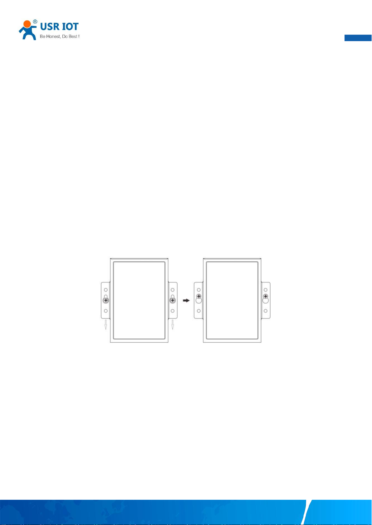
Align the wall mount plate over the screws on the wall. Hang the device on two screws and slide it downward to lock in place,
then tighten the screw to enhance stability, see the following Fig.1.
Fig. 1 Wall mount installation
For device disassembling please power off the device and unscrew the screw on the wall about 2mm. Lift the device upward
slightly, take out the device,
2.1.2. DIN-Rail mounting
DIN-Rail mount kits must be purchased separately. They are not provided with the N5X0.
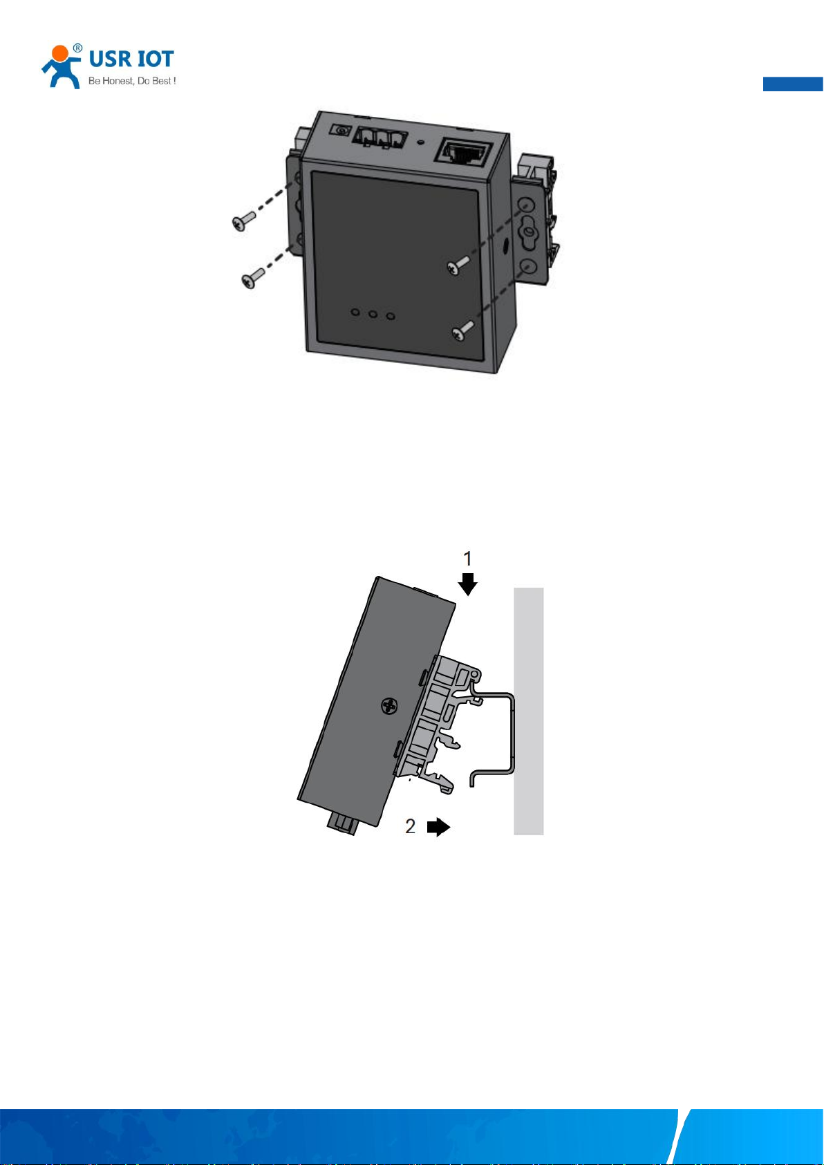
If you have purchased the DIN-Rail mount kit, proceed to place the screws on the back of the device as show in Fig.2.
Your TrustWorthy Industrial IoT Partner www.pusr.com
Page 9
User Manual
8
Fig. 2 Fix DIN-Rail mount kit
Position the rear panel of the device directly in front of the DIN-Rail, making sure that the top of the DIN-Rail clip hooks over the
top of the DIN-Rail , as shown in Fig.3.
Fig. 3 Install DIN-Rail mounting kit
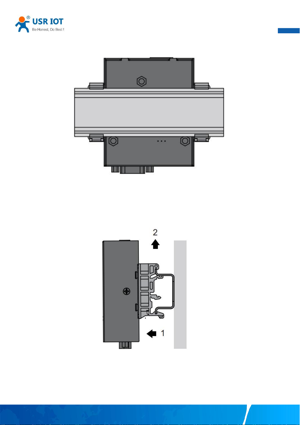
Once the DIN-Rail is seated correctly in the DIN-Rail clip, press the front of the device to rotate the device down and into the
release tab on the DIN-Rail clip. If seated correctly, the bottom of the DIN-Rail should be fully inserted in the release tab.
Your TrustWorthy Industrial IoT Partner www.pusr.com
Page 10
User Manual
9
Fig. 4 Correctly installed DIN-Rail kit
Proceed to Fig.5 if you want to remove the device from DIN-Rail. Push down on the top of the DIN rail clip release tab with your
finger. As the clip releases, lift the bottom of the device, as shown in the following illustration.
Fig. 5 Remove the DIN-Rail
2.2. Serial port
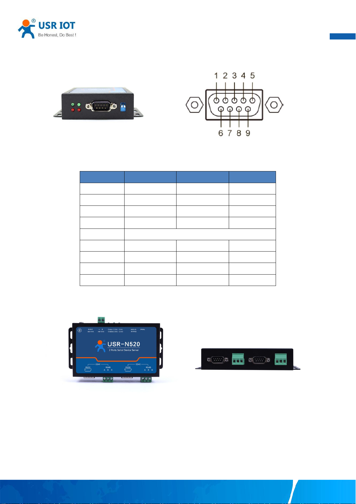
The USR-N5X0 supports the RS-232, RS-422, and RS-485 protocols,adopts DB9 male connector and is software configurable. The
serial port pin assignments are given in the table 2.
Your TrustWorthy Industrial IoT Partner www.pusr.com
Page 11
10
Fig. 6 DB9 male connector pin
Pin
RS232
RS422
RS485
1----
--
2
RXD
Rx+
3
TXD
Tx-
B-
4
5
GND
6
7
RTS
Tx-
A+
8
CTS
Rx-
9
Table 2 DB9 Male Pin Assignment(N5X0 models)
User Manual
The USR-N5X0-6 supports the RS-232 and RS-485 protocols, and is software configurable. And RS232 adopts DB9 male
connector,RS485 adopts terminal block. The DB9 pin assignment is same to table 2(RS232).
Fig. 7 N520-6 serial port
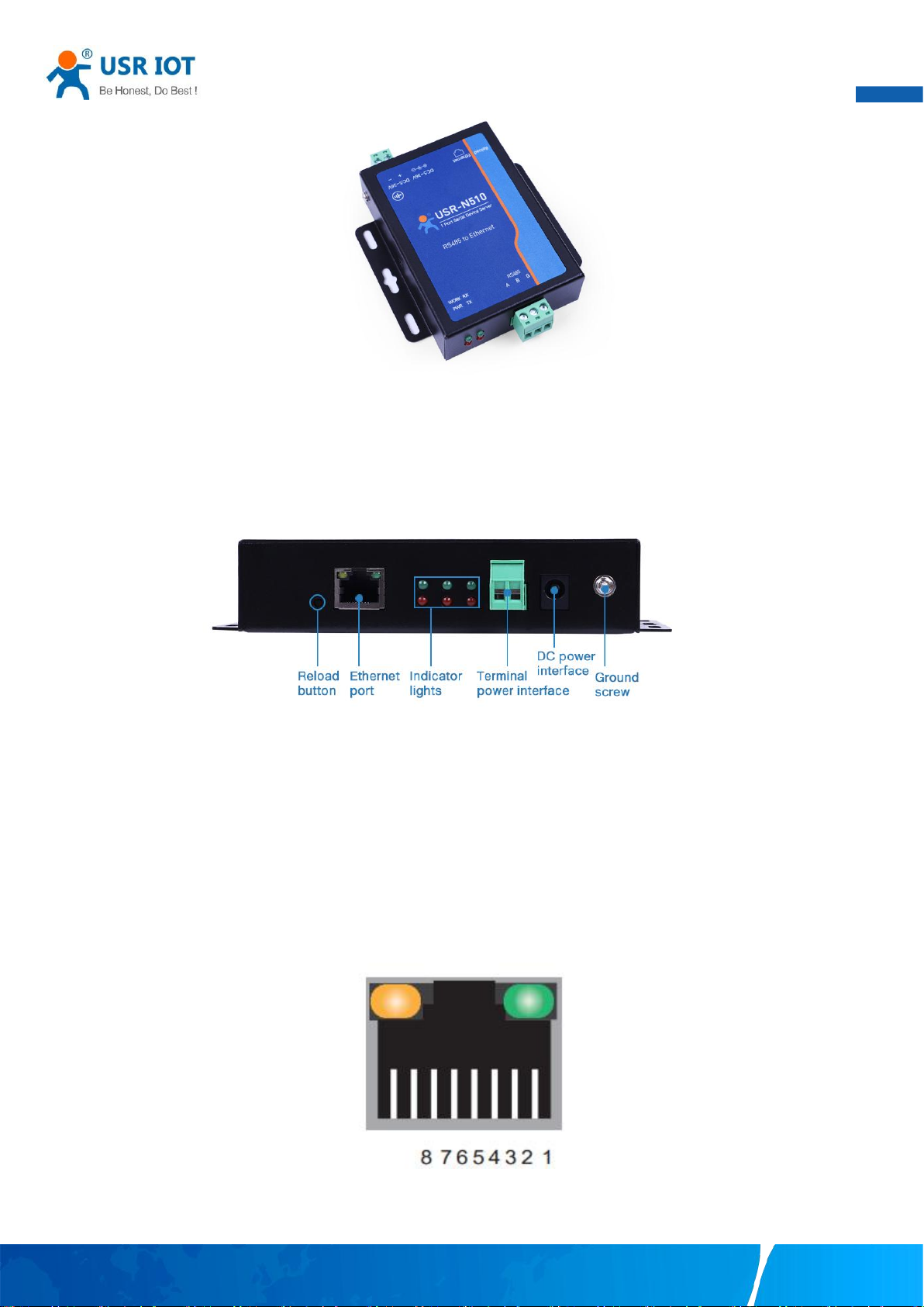
The USR-N5X0-4 supports only RS-485 protocols, and adopts 3-pin 5.08mm pitch industrial terminal blocks. The serial port pin
assignments are shown in Fig.8.
Your TrustWorthy Industrial IoT Partner www.pusr.com
Page 12
User Manual
11
Fig. 8 N510-4 terminal block
2.3. Power supply
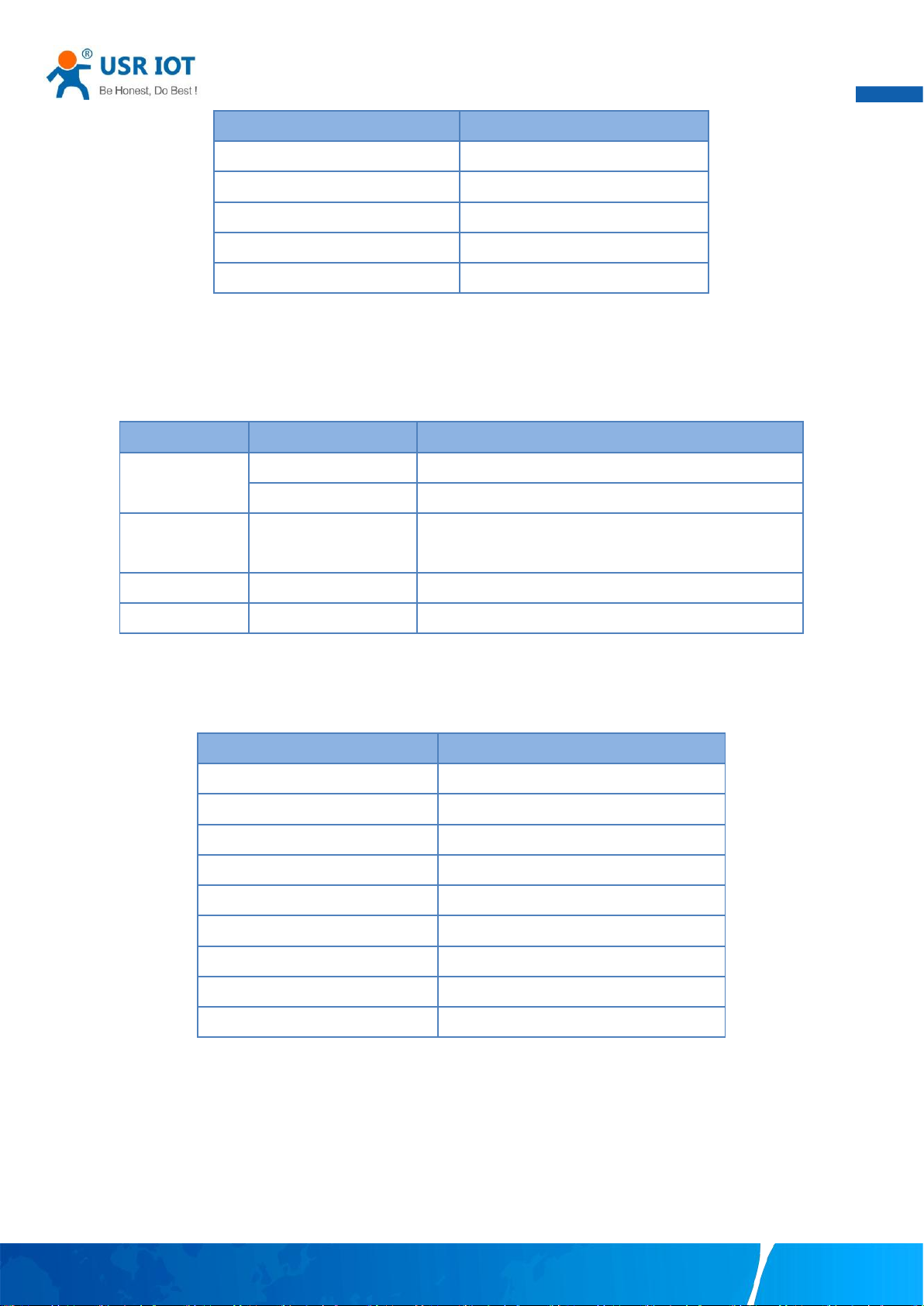
The USR-N5X0 serial device server provides 2-pin power supply input terminal blocks and DC jack. The power supply support
anti-reverse protection. Power supply range: 5~36VDC.
Fig. 9 N520 back view
Although internal grounding has been done inside, in order to help limit the effects of noise caused by electromagnetic interference
(EMI) and protect your device, it is still strongly advised to ground the device properly. There is a grounding screw next to the terminal
block,you should connect it to the grounding at all times.
2.4. Ethernet RJ45 interface
The 10Base-T/100Base-TX adaptive Ethernet RJ45 interface supports automatic MDI/MDIX connection, refer to Fig.10 below for the
pin distribution of the RJ45 interface. USR-N5X0 serial servers adopt RJ45 interface with light, as shown in the picture below.
Fig. 10 RJ45 with light
Table 3 Ethernet pin assignments
Your TrustWorthy Industrial IoT Partner www.pusr.com
Page 13
User Manual
12
Pin number
Signal name
1
Send data+(TD+)
2
Send data-(TD-)
3
Receive data+(RD+)
6
Receive data-(RD-)
4,5,7,8
Unused
LED name
status
description
PWR
Steady on
Power supply is normal
Off
No power supply or abnormal power supply
WORK
Blinking
Power is on and the device is ready. System is booted up
and running
TXN
Blinking
Serial port is transmitting data
RXN
Blinking
Serial port is receiving data
Parameter
Default Values
User Name
admin
Password
admin
Device IP
192.168.0.7
Subnet Mask
255.255.255.0
Gateway IP
192.168.0.1
COM port
115200,None,8,1
COM operation mode
TCP server,23
MQTT
Disable (firmware V2 version)
Edge computing
Disable (firmware V2 version)
2.5. LED indicators
The USR-N5X0 serial device server provides LED indicators to monitor the device working status with a comprehensive simplified
troubleshooting, the function of each LED is described in the table as below.
Table 4 LED indicators
2.6. Factory default settings
The USR-N5X0 serial device server comes with the following default settings.
Table 5
Default parameters
2.7. Quick test
USR-N5X0 series serial server has a built-in Web server, which provides a convenient way to access and configure the serial server.
Users can use Edge , Firefox or Google browser to access it. This chapter is a quick introduction to the USR-N5X0 series of serial
server products. It is recommended that users read this chapter and follow the instructions once for the system, and you will have a
basic understanding of the product. For specific function details and instructions, please refer to the subsequent chapters.
Your TrustWorthy Industrial IoT Partner www.pusr.com
Page 14
User Manual
13
2.7.1. Download the software
Download the setting software from PUSR’s website:
https://www.pusr.com/support/downloads/H7-version-set-up-software.html
https://www.pusr.com/support/downloads/usr-tcp232-test-V13.html
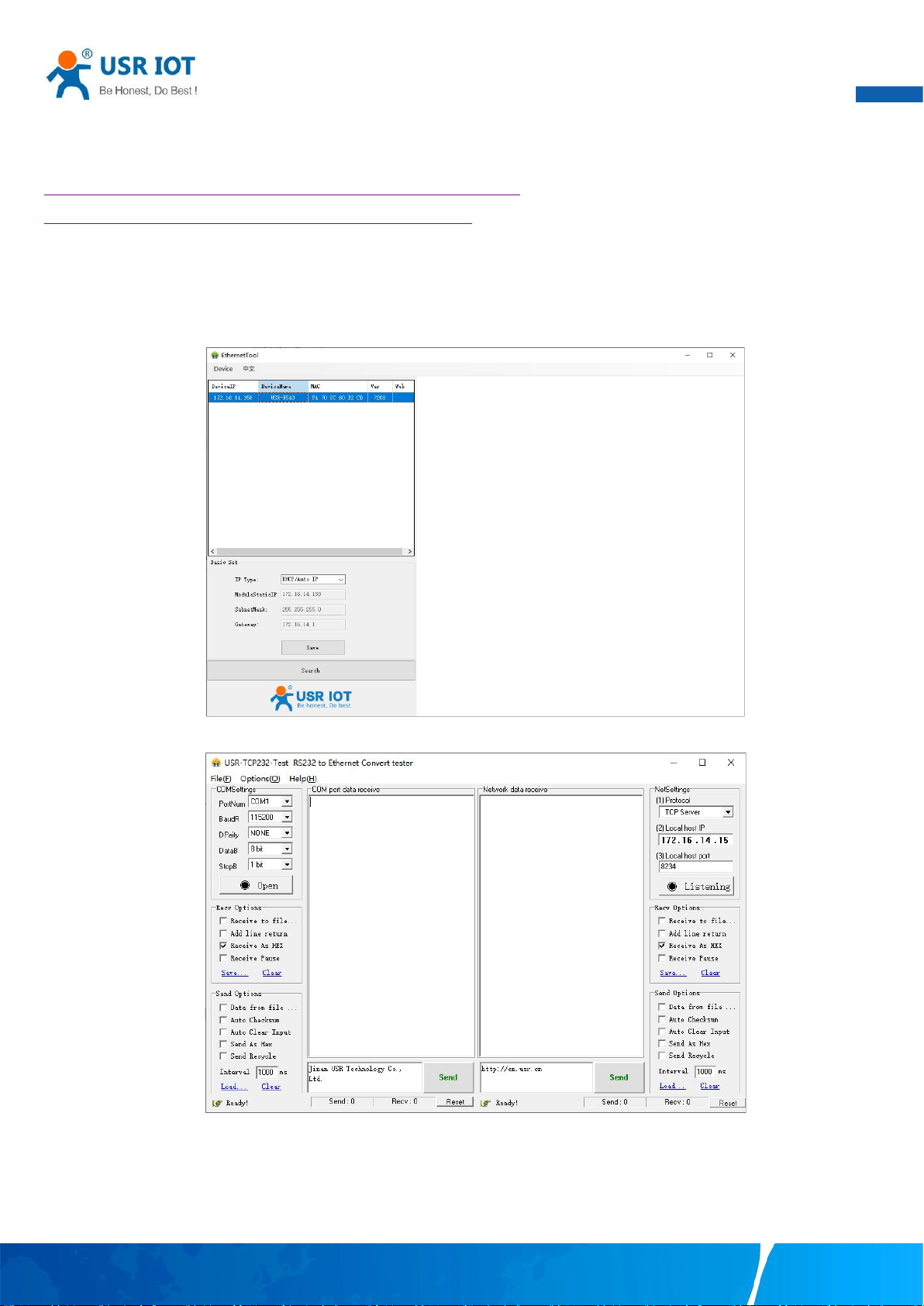
You may find it in the download section under your product page. Run the software when the installation has been completed as
shown in Fig.11 and Fig.12.
It is strongly recommended for the users to set the Network Parameters through configuration tool first. Other device-specific
configurations can later be carried out via user-friendly Web-Interface.
2.7.2. Hardware connection
Fig. 11 Windows configuration tool
Fig. 12 Test assistant
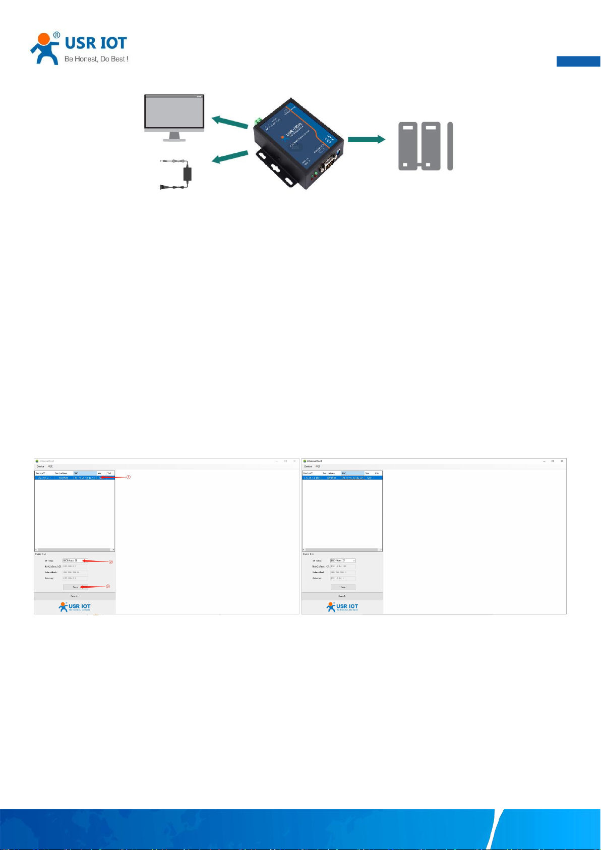
For fast networking of USR-N5X0 series serial server, you need to prepare a PC, a router, a serial server, a network cable, a serial
cable, and a DC12V/1A power supply. The hardware connection is shown in Fig. 13. To establish a TCP / IP network all devices must be
Your TrustWorthy Industrial IoT Partner www.pusr.com
Page 15
User Manual
14
connected to the same network either locally or via gateway connections.
Fig. 13 Hardware connection
Connect the power line with the N5X0 power input. If the power is properly supplied, the “PWR” LED will show a solid red color.
After the system is ready, the “WORK” LED will blink.
Connect one end of the Ethernet cable to the N5X0’s 10/100M Ethernet port and the other end of the cable to the same Ethernet
network(same router or switch).
Connect a serial data cable(USB to RS232 or RS485) between the N5X0 and PC.
2.7.3. Network configuration(Step1)
The Broadcast Search function is used to locate all N5X0 device servers that are connected to the same LAN as your computer. Since
the Broadcast Search function searches by MAC address and not IP address, all N5X0 connected to the LAN will be located,
regardless of whether or not they are part of the same subnet as the host.
In EthernetTool, click Search to search your LAN for N5X0 device servers. When your unit appears in the search results, you can click
device to select it and change the IP type to DHCH, save your change. Wait for 5s and search it again.
Fig. 14 IP network setting
When accessing the serial server through the Web, the IP address of the serial server and the PC must be in the same network
segment. After changing the IP address of the N5X0, you can access the Web page of the N5X0 series serial server through browser
and perform related configuration operations on it. The user name and initial password are both "admin".After entering the user name
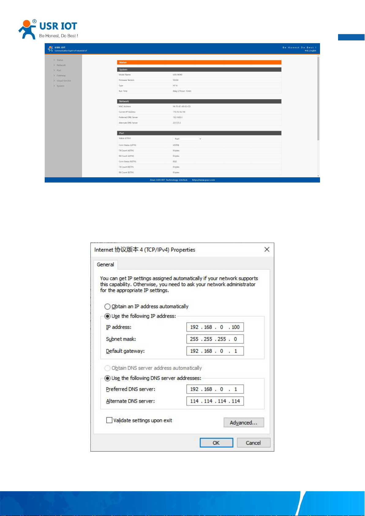
and password, click "OK" and the server will authenticate. After success, you will enter the main page of the Web server, as shown in
Fig.15. The following uses firmware V2 version as an example. For details about the V1 version web page, see Section 3.1.
Your TrustWorthy Industrial IoT Partner www.pusr.com
Page 16
User Manual
15
Fig. 15 The main interface of the Web server
The IP address of the PC must be modified to ensure that it is in the same local area network as the IP of the serial server if you want
to connect N5X0 to PC directly via a net cable. The default IP address of serial server is: 192.168.0.7. Set the PC's IP address as:
192.168.0.X (X is any valid value from 2 to 253 except 7). The specific Windows system operation page is shown in Fig.16. you can
access the Web page of the USR-N5X0 series serial server through browser as mentioned above.
Fig. 16 IP setting of PC
2.7.4. Data transmission test(Step2 and 3)
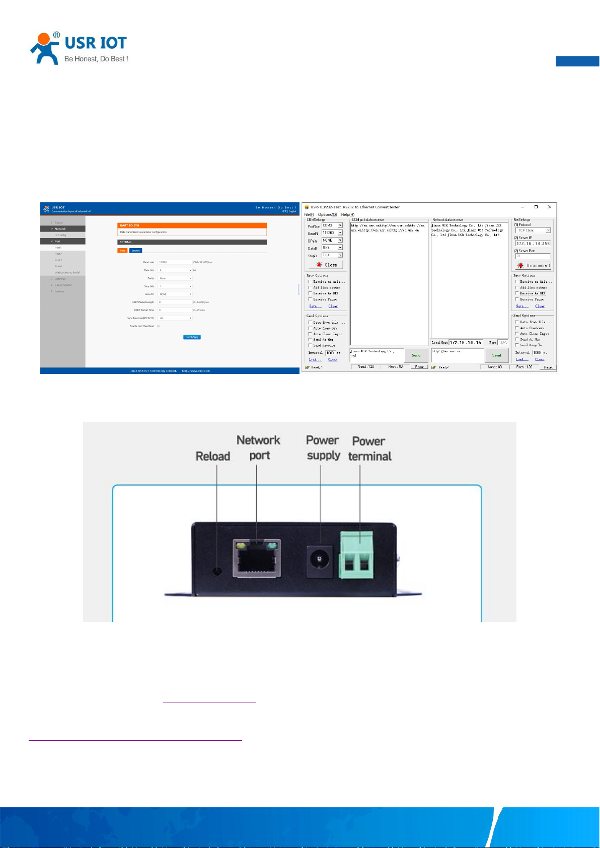
You can select an operation mode in socket setting page, but for now we use default parameters to test, i.e TCP server. Now
Your TrustWorthy Industrial IoT Partner www.pusr.com
Page 17
User Manual
16
USR-TCP232-Test works as TCP client, you need configure the server IP and port, that is 172.16.14.158:23 of USR-N5X0 serial device
server, the IP address of PC is 172.16.14.15.
In the serial port setting module, you can configure communication parameters for the serial ports RS485 and RS232, as shown in the
figure below. When configuring a serial network you need to set the following within each device-Baud rate,Parity,Stop bits,Data bits
and keep serial port parameters consistent in the same network. We now configure the COM Settings to operate as required for the
N5X0 devices. Go to the Port1 Settings tab for confirming values of parameters.
Fig.17 shows an example of parameters setting to test transparent transmission.
Fig. 17 Transparent transmission test
2.8. Reload factory settings button
Press the “ Reload” button (inside a small hole) on the back panel for 3-15 seconds and then release or follow the procedure in
Section 3.1.6, to restore the USR-N5X0 Series Industrial Serial Device Server to the factory default settings.
2.9. Technical support and assistance
Please visit the USR IoT website: https://www.pusr.com where you can find the latest information about the product.
Contact your distributor, sales representative, or PUSR's support center:
http://h.usriot.com/index.php?c=frontTicket&m=sign for technical support if you need additional assistance. Please have the following
information ready before you submit a ticket:
– Product model
– Description of your peripheral attachments
Your TrustWorthy Industrial IoT Partner www.pusr.com
Page 18

17
– Description of your software (firmware version, application,function description,etc.)
– A complete description of the issue and steps to reproduce
User Manual
Your TrustWorthy Industrial IoT Partner www.pusr.com
Page 19
User Manual
18
3. Configuration and parameter details
3.1. Web interface(V1 version)
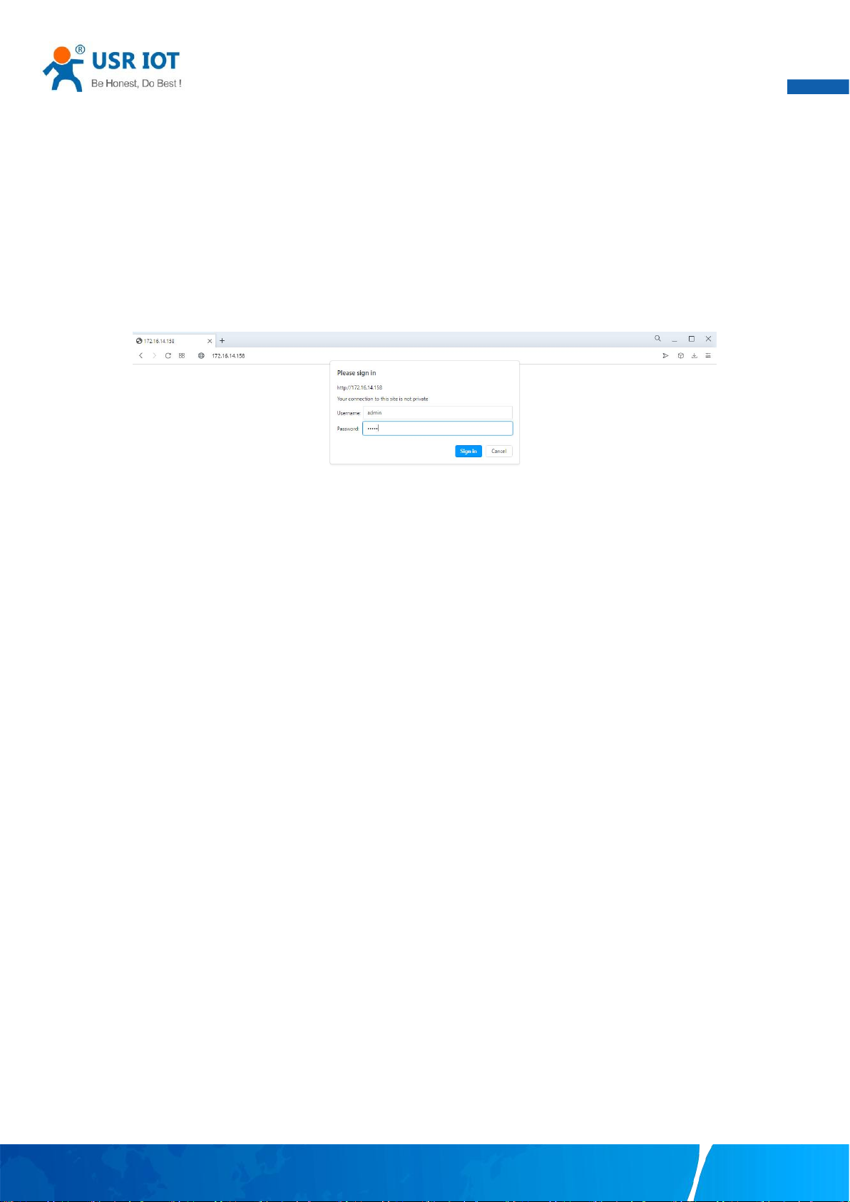
Every USR-N5X0 Industrial Serial Device Server is equipped with a built-in web server in the firmware. Therefore, the device can be
accessed by using a web browser for configuring by entering the device’ s IP address in the URL field of your web browser. An
authentication will be required and you will have to enter the username (Default value is “admin”) and password (Default value is
“admin”) for accessing the web interface as shown in Fig. 18. This approach (web interface) for configuring your device is the most
user-friendly. It is the most recommended and the most common method used for USR-N5X0 Serial Device Server Series. Please go
to its corresponding section for a detailed explanation.
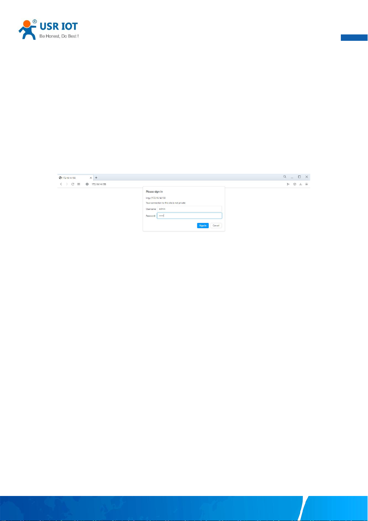
Fig. 18 Authentication Required for Accessing Web Interface
3.1.1. Status
After entering the correct user name and password and the authentication is successful, you will enter the main page of the Web, as
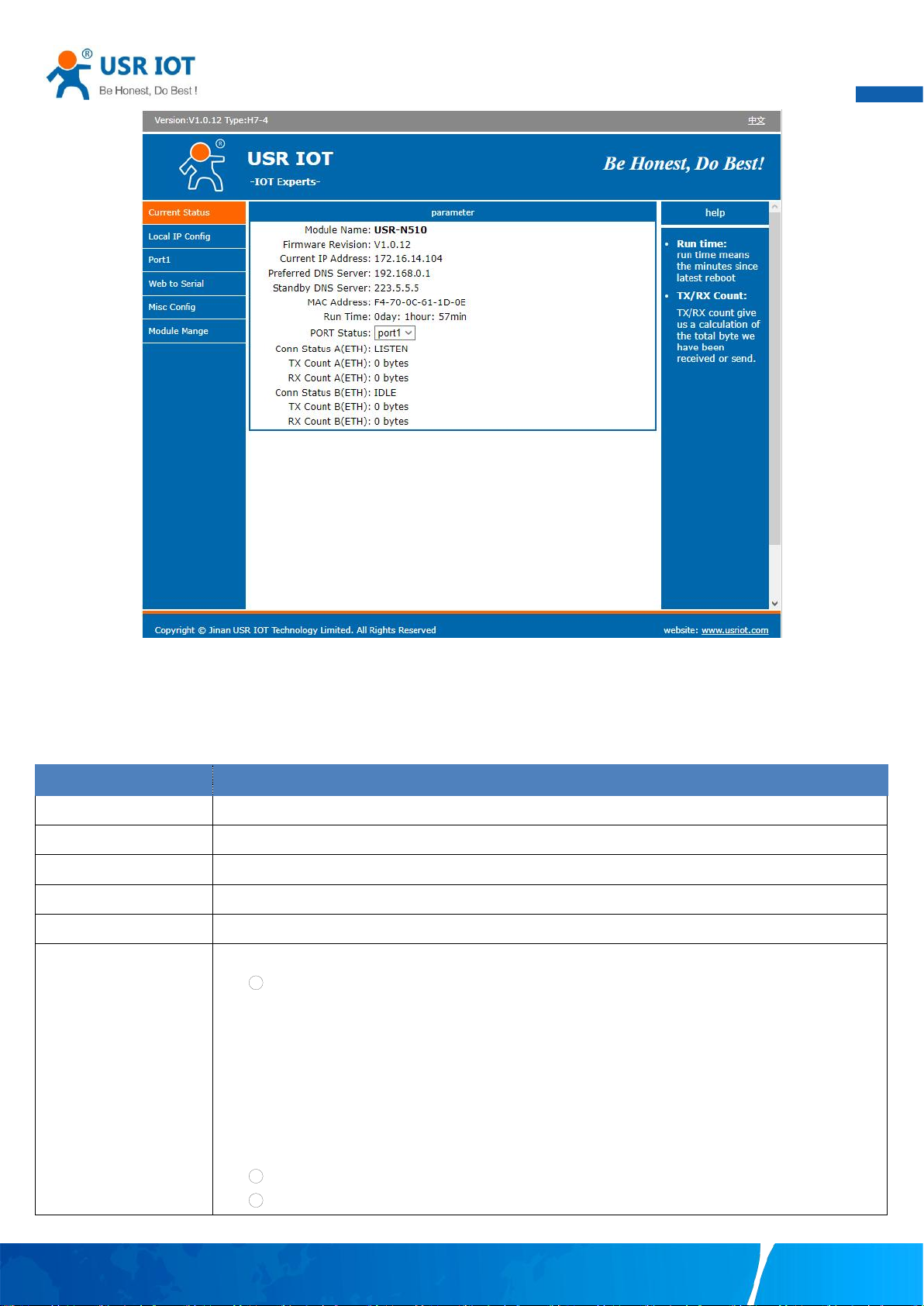
shown in Fig.19. The main page can be roughly divided into three areas. The upper area displays the logo, the lower left area is the
function menu area, the middle area is the main function display area, and the lower right area is the help document area. Fig.19
illustrates the status page of the web interface.
Your TrustWorthy Industrial IoT Partner www.pusr.com
Page 20
User Manual
19
Parameter Item
Description
Module name
The name of the serial server, which can be customized by the user on the "Miscellaneous settings" page.
Firmware version
The current software version of the serial server.
IP address
The IP address of the serial server.
MAC address
The MAC address of the serial server.
Running time
Total time after the device start work. It will starts from 0 after reboot.
Port status
The working status of checked serial port. Select the serial port currently to be displayed
1 Conn Status A(ETH): connection status of socket A.
IDLE:Initialization status
LISTEN:When the module works as TCP Server, it is listening for connection access
CONNECTING:Works as TCP client, the module is establishing a connection to the TCP Server
CONNECTED:Works as TCP server, the TCP connection to TCP server of the module has been
established
CONNECTED(n):Number of TCP clients connected to the module
ERROR:The module is abnormally disconnected
2 Tx Count A(ETH): To count how many bytes be send to internet.
3 Rx Count A(ETH): To count how many bytes received from internet.
Fig. 19 The main interface of the Web server
The function of the device status part is to display some specific information of the current device, including module name,firmware
version, IP address, DNS, MAC address, running time and serial port status.
Table 6 Status list
Your TrustWorthy Industrial IoT Partner www.pusr.com
Page 21
User Manual
20
Parameter Item
Description
Network protocol
Click the drop-down menu to select the IP Address Setting mode: Static or DHCP. If you choose DHCP,
the rest of the options will be greyed out or disabled.
DNS type
Click the drop-down menu to select the DNS mode: auto or manual. If you choose auto, the DNS options
will be greyed out or disabled.
IP address
IP address is a 32-bit address assigned to devices connected to the Internet. The IP address consists of
two fields: the network number field (Net-id) and host number field (host-id). In order to facilitate the
management of IP addresses,IP addresses are divided into five categories: Class A, B, and C addresses
are unicast addresses, Class D addresses are multicast addresses, Class E addresses are reserved
addresses for future special purposes. The IP addresses currently in large numbers belong to three types
of addresses: A, B, and C.
Subnet mask
The mask is a 32-bit number corresponding to an IP address. Some of these numbers are 1, and the
others are 0. The mask can divide the IP address into two parts: the subnet address and the host address.
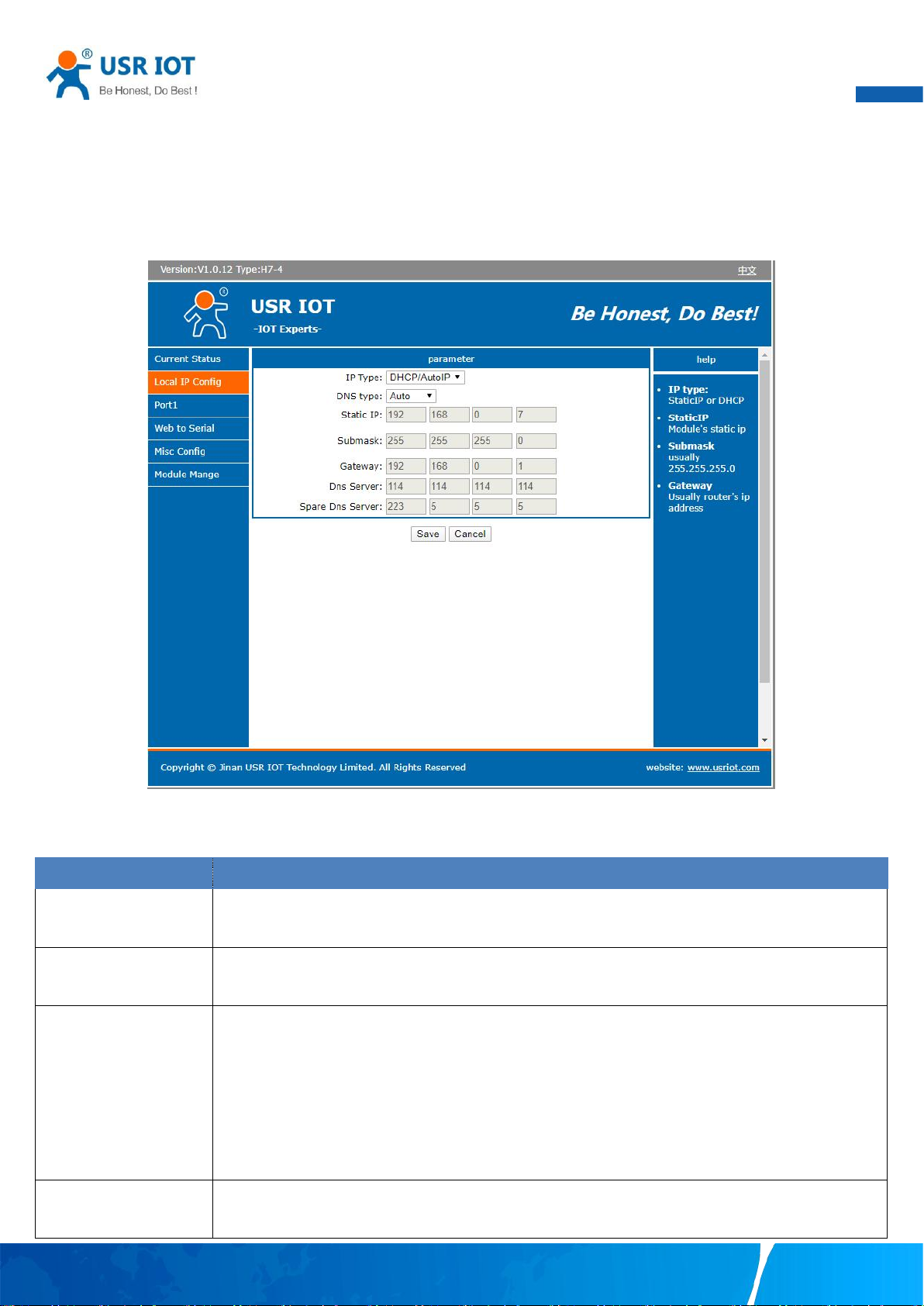
3.1.2. IP settings
You must assign a valid IP address to the USR-N5X0 before it will work in your network environment. The IP address must be unique
within the network. If the device is connected to the Internet and should connect to other servers over the Internet to get some
services such as Network Time Protocol (NTP) server, you will need to configure the DNS server in order to be able to resolve the host
name of the NTP server. The detailed description of the configuration parameters on this interface is shown in table 7.
Fig. 20 Network Settings Web Page
Table 7 Network settings list
Your TrustWorthy Industrial IoT Partner www.pusr.com
Page 22
User Manual
21
The part of the IP address corresponding to the 1 bit in the mask is the subnet address, and the other bits
are the host address. The mask for class A addresses is 255.0.0.0, the mask for class B addresses is
255.255.0.0, the mask for class C addresses is 255.255.255.0.
Default gateway
The default gateway in the host is usually called the default route. The default route (Default route) is the
route chosen by the router when no other route exists for the destination address in the IP packet. All
packets whose destination is not in the router's routing table will use the default route.
DNS
The IP address of the DNS server. DNS Server part is where you can specify the IP Address of your
Preferred DNS (Domain Name Server) and Alternate DNS. When the device uses a static IP address, the
user is required to fill in this item, 8.8.8.8(Google) will be a good choice. If a specific DNS server is not
used, the default gateway IP address is generally sufficient.
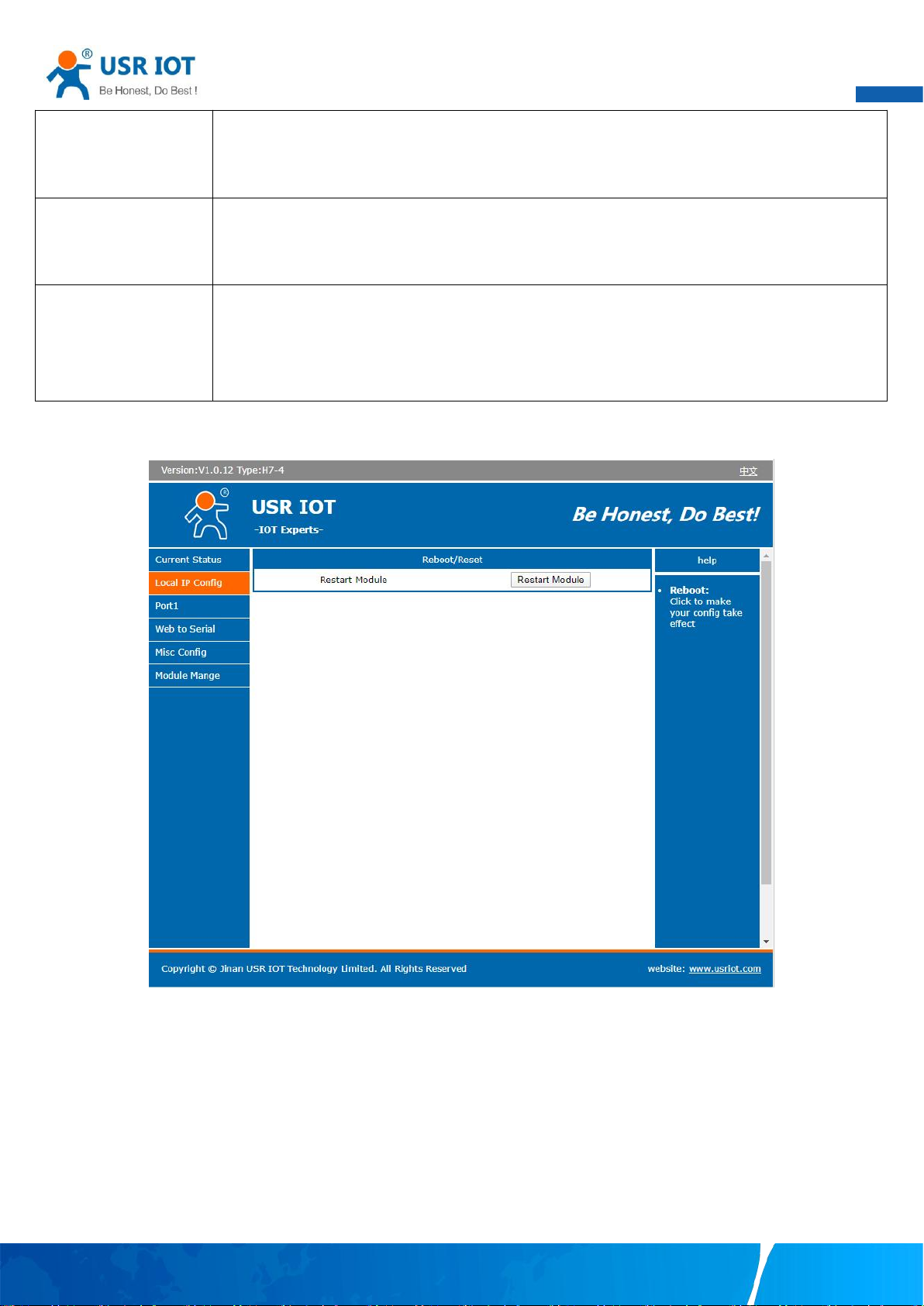
After finishing the network settings configuration, please click the Save button to save all changes that have been made. Finally, the
web browser will be redirected to the Reboot page as shown in Fig.21. All modified parameters take effect after device restart.
Fig. 21 Reboot web page
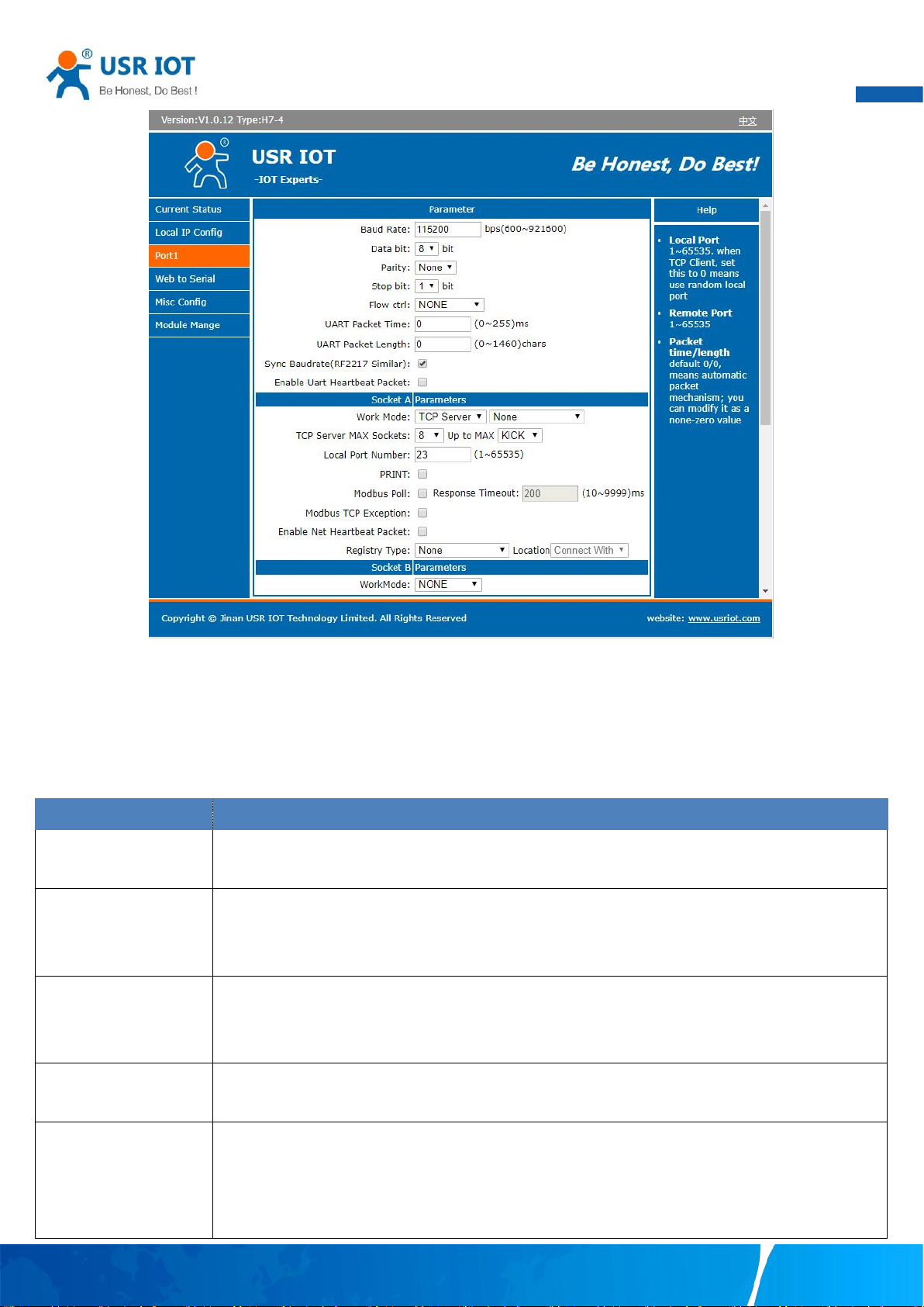
3.1.3. Serial port settings
The serial port module includes: serial port parameter configuration, network parameter configuration. The main function of the serial
device server is to carry out two-way transparent transmission of standard serial bus data (RS-232, RS-485, RS-422) and standard
Ethernet data supporting TCP/IP protocol to solve common serial equipment Networking problems on the Internet. The Port
configuration page can configure the parameters of the serial port and socket, as shown in Fig.22.
Your TrustWorthy Industrial IoT Partner www.pusr.com
Page 23
User Manual
22
Parameter Item
Description
Baud rate
This sets the port’s data transfer speed. Choices are from 600—921600. Set this to match the baud rate
setting of the connected device. Default is 115200.
Data bits
This sets the number of bits used to transmit one character of data. Choices are: 7 and 8. Set this to
match the data bit setting of the connected device. Default is 8 (which is the default for the majority of
serial devices).
Parity bits
This bit checks the integrity of the transmitted data. Choices are: None, Odd, Even. Set this to match the
parity setting of the connected device. Default is None (which is the default for the majority of serial
devices).
Stop bits
This indicates that a character has been transmitted. Set this to match the stop bit setting of the
connected device. Choices are: 1 and 2. Default is 1 (which is the default for the majority of serial devices).
Flow control
This allows you to choose how the data flow will be controlled. Choices are: (No Flow Control), RTS/CTS
(Hardware Flow Control), or Xon/Xoff (Software Flow Control). Set this to match the flow control setting of
the connected device. Default is None. If Xon/Xoff is selected, the Xon and Xoff characters are 0x11 for
Xon and 0x13 for Xoff. Note that these are hexadecimal numbers of ASCII characters (i.e., 0x11 = ‘1’ and
Fig. 22 Serial port configuration page
Details on work mode connectivity protocols and its settings of N5X0 series are given in Chapter 4 Operation modes, this section
will only focus on the part of parameter description. The description of the configuration parameters on this interface is shown in
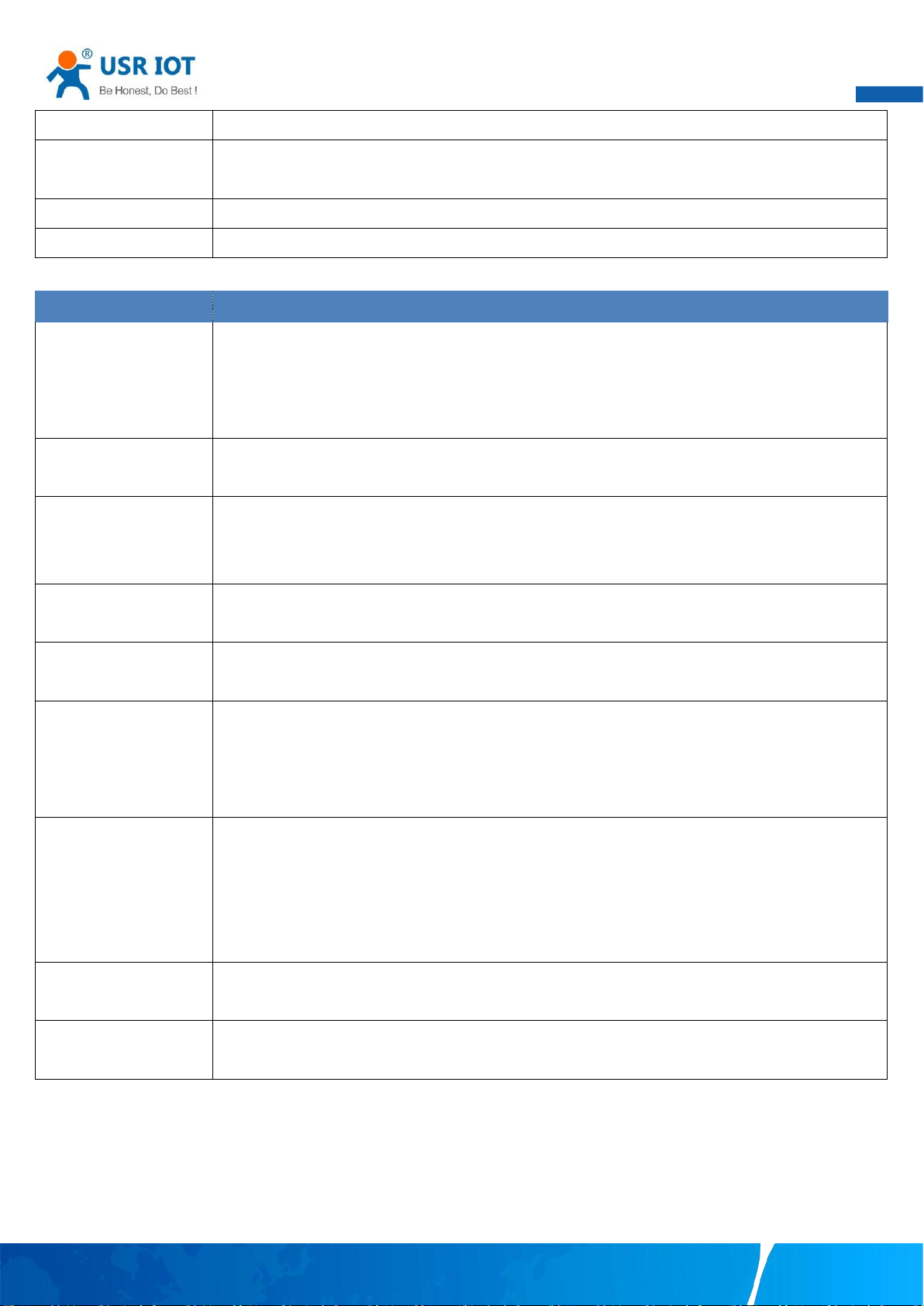
table 8 and table 9.
Table 8 Serial settings
Your TrustWorthy Industrial IoT Partner www.pusr.com
Page 24
23
0x13 = ‘3’).
Serial mode(N5X0
models)
Click the drop-down menu to select the type of serial interface for the port. Choices are RS-232,RS-422,
RS-485 (2 Wire).
Packing time
Click the option to sent pack immediately by interval.
Packing length
Click the option to sent pack immediately by size.
Table 9 Operating modes settings
Parameter Item
Description
Work mode
USR-N5X0 series supports 5 different operation Modes which are TCP Server, TCP Client, and UDP,HTTP
client and websocket. The operation Mode describes the role of the device and the connection between
the device and other remote devices in the network which would like to communicate with serial device
on N5X0’s COM port.
Maximum socket no.(TCP
server only)
This option specifies the maximum number of remote devices/clients (with maximum of 16 clients, except
N580 with 8) that can be connected to the serial device on this COM port.
Local port
This option specifies the port number that the TCP/UDP server should listen to. It is also used by the
remote TCP/UDP client to connect to the TCP/UDP server. The default local port is 23. You can enter
different port numbers in this option.
Remoter server addr.
Please specify the IP address of the TCP/UDP server program on the remote host in this field. This should
match the IP settings of the TCP/UDP server program.
Remote port
Please specify the port number of the TCP/UDP server program on the remote host in this field. Once
again, this should match the IP setting of the TCP/UDP server program.
Timeout
reconnection(TCP/UDP
client)
The default is disable. If you want to keep connection continually, you can disable it. Data idle Time is the
time period for which the device waits for data. If the USR-N5X0 Series does not receive data during
established idle time(timeout), the USR-N5X0 Series will disconnect temporarily. When the data comes
in, it will reconnect automatically. Users do not need to reconnect.
Modbus polling
This option is selected when multiple modbus maters from Ethernet are polling the same serial port.
Each serial port supports up to 16 simultaneous TCP connections allowing hosts to simultaneously
transmit/receive data to/from the same serial port,USR-N5X0 Series processes the data in the order
arrived. The serial device server determines the end of the serial acknowledgement through a response
timeout.
Modbus exception
This option is used to enable modbus exception checking. If selected, error messages (TCP exception
codes) are generated if a problem (such as a message timeout) should occur during Modbus operations.
Socket B
Socket B supports 2 different operation Modes which are TCP Client, and UDP client, this socket is closed
by default.
User Manual
The configuration will save to flash memory after clicking Save button. All configurations take effect after a system reboot.
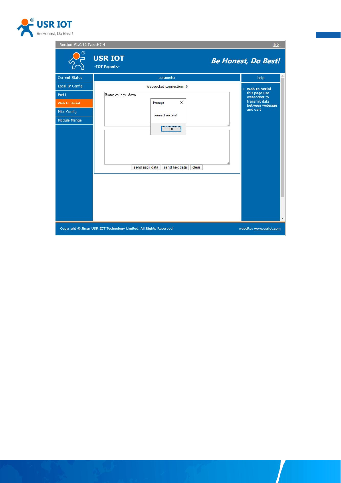
3.1.4. Websocket server
This function is that the serial server acts as a WebSocket server, and transparently transmits the data received by the serial to the
webpage in hexadecimal or ascii format. The WebSocket server can also send data to the serial device at any time.
Your TrustWorthy Industrial IoT Partner www.pusr.com
Page 25
User Manual
24
Fig. 23 Websocket server
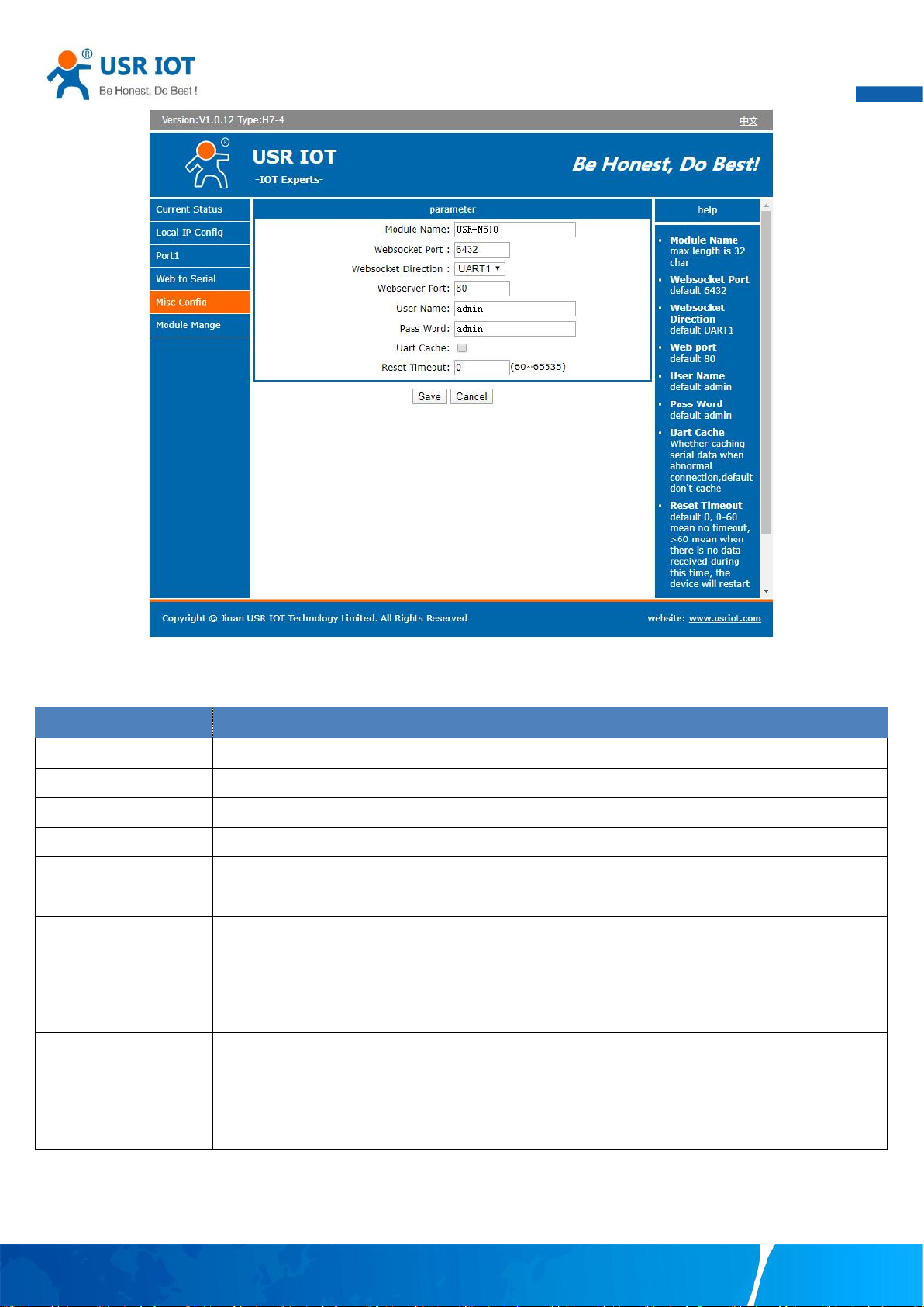
3.1.5. Miscellaneous settings
This configuration tab includes several system level settings, such as device name, websocket, system log, user name and password.
Most of these settings are optional.
Your TrustWorthy Industrial IoT Partner www.pusr.com
Page 26
User Manual
25
Parameter Item
Description
Module name
The name of the device, up to 32 characters,can’t be null
Websocket port
Websocket server listen port NO. Range 1-65535
Websocket direction
Click the drop-down menu to select websocket mapping direction: UART or Log.
Webserver port
Web server listen port NO. Range 1-65535
User name
The user name of web console and can be modified. up to 16 characters,can’t be NULL
Password
The password of web console and can be modified. up to 16 characters,can’t be NULL
UART cache
Click the option to enable serial buffer. By default, N5X0 will empty its serial buffer when a new TCP
connection is established. This means that the TCP application will not receive buffered serial data during
a TCP link breakage. To keep the serial data when there is no TCP connection and send out the buffered
serial data immediately after a TCP connection is established, you can disable this option.
Reset timeout
This function is used for the serial device server without any data transmission or reception for a long
time, and the serial server automatically restarts. If the restart time is set between 0 and 59 seconds, this
function does not take effect. Only when the time is set to be greater than or equal to 60 seconds, the
restart function of the device without data will take effect.
Fig. 24 Miscellaneous settings
Table 10 Miscellaneous settings
The configuration will save to flash memory after clicking Save button. All configurations take effect after a system reboot.
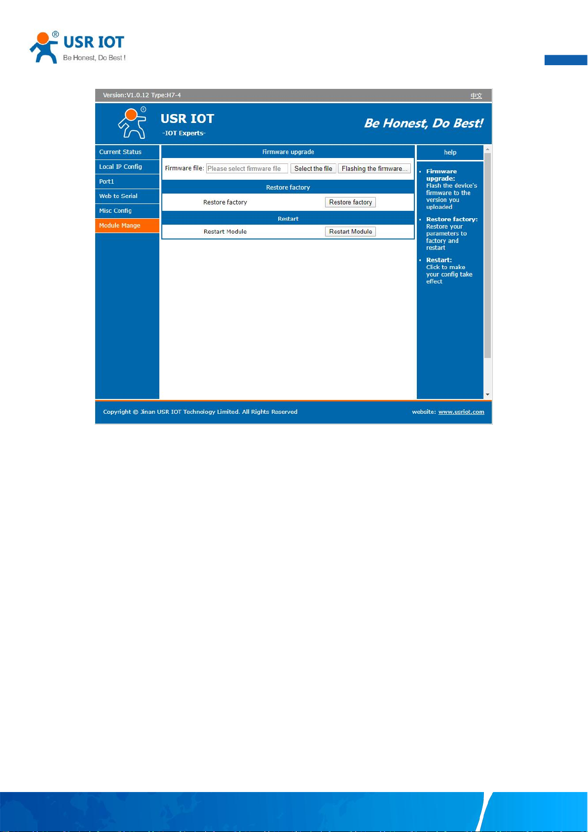
3.1.6. Management
This page can perform some system operations on the N5X0 series serial server, including restarting, restoring factory configuration,
Your TrustWorthy Industrial IoT Partner www.pusr.com
Page 27
User Manual
26
and upgrading. It is recommended that users use it with caution. Improper operation may damage the serial server.
Fig. 25 Module management
Reboot
This function is used to restart the USR-N5X0 series serial server by software. Before the serial server is completely restarted, the
device does not work and cannot forward any data packets. This restart is different from the hardware reset of power-on restart, but
the serial server system software is reset, just like the "warm restart" of the windows operating system. Once a new setting is changed,
you can use the Save function to accept the changes. You will need to reset the device to save the settings to flash memory. Click on
"restart module" Button, the page pops up a prompt box, click "yes".
Restore factory defaults
This function is used to restore the USR N5X0 serial server to the factory settings and automatically restart the serial server at the
same time. Before the serial server restarts successfully, the serial server does not work and cannot forward any data packets. This
function is to restore the factory default configuration value once the user sets the wrong parameter and causes the serial port server
to work abnormally. Click the "Restore factory" button, and a prompt box will pop up on the page. Click "yes".
Firmware upgrade
USR IoT continually upgrades its firmware to add new features and optimize performance. Please contact the sales to obtain the
latest version of the firmware. Before upgrading the firmware, please make sure that the device has a reliable power source that will
not be powered off or restarted during the firmware upgrading process(please be patient as this whole process might take up to 1 -2
minutes).
Copy the new firmware file to your local computer. Note that the firmware file is a binary file with “.bin” extension. Before updating
the firmware, make sure that your host’s Network domain is as same as the serial device server.
Next, click “Select the file” button as shown in Figure to find and choose the new firmware file. Then, click "Flashing the firmware"
Your TrustWorthy Industrial IoT Partner www.pusr.com
Page 28
User Manual
27
button to start the firmware upgrade process. The program will show the upload status. Please wait until the uploading process is
finished (the amount of time varies depending on the equipment used).
Finally, the device will then proceed to restart itself. In most cases, you might require to re-configure your device.
Please refer to “USR-N5X0 firmware upgrade from V1 to V2 version user guide” for detail if you want to use V2 firmware function.
3.2. Web interface(V2 version)
Every USR-N5X0 Industrial Serial Device Server is equipped with a built-in web server in the firmware. Therefore, the device can be
accessed by using a web browser for configuring by entering the device’ s IP address in the URL field of your web browser. An
authentication will be required and you will have to enter the username (Default value is “admin”) and password (Default value is
“admin”) for accessing the web interface as shown in Fig. 26. This approach (web interface) for configuring your device is the most
user-friendly. It is the most recommended and the most common method used for USR-N5X0 Serial Device Server Series. Please go
to its corresponding section for a detailed explanation.
Fig. 26 Authentication Required for Accessing Web Interface
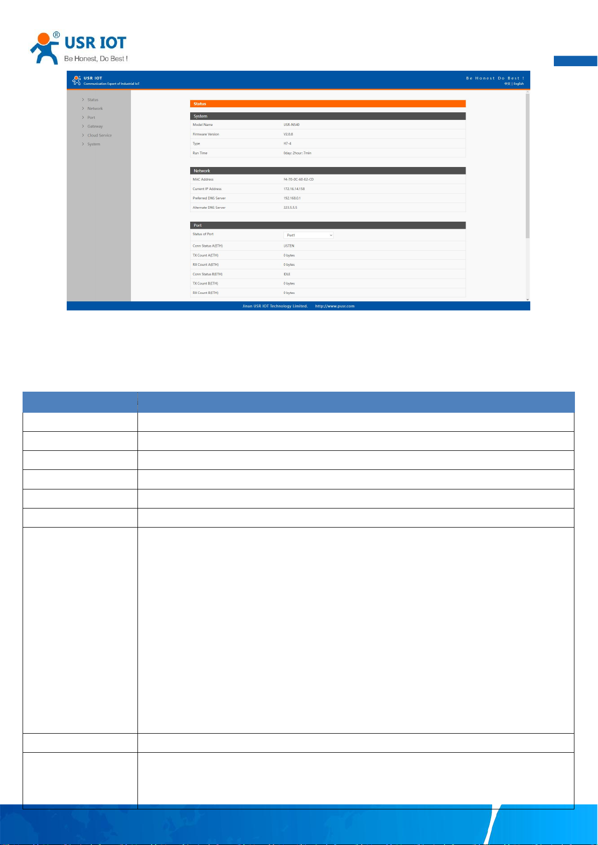
3.2.1. Status
After entering the correct user name and password and the authentication is successful, you will enter the main page of the Web, as
shown in Fig.27.
Your TrustWorthy Industrial IoT Partner www.pusr.com
Page 29
User Manual
28
Parameter Item
Description
Model name
The name of the serial server, which can be customized by the user on the "Miscellaneous settings" page.
Firmware version
The current software version of the serial server.
Type
The current hardware version of the serial server.
Running time
Total time after the device start work. It will starts from 0 after reboot.
MAC address
The MAC address of the serial server.
IP address
The IP address of the serial server.
Port status
The working status of checked serial port. Select the serial port currently to be displayed
Conn Status A(ETH): connection status of socket A.
IDLE:Initialization status
LISTEN:When the module works as TCP Server, it is listening for connection access
CONNECTING:Works as TCP client, the module is establishing a connection to the TCP Server
CONNECTED : Works as TCP server, the TCP connection to TCP server of the module has been
established
CONNECTED(n):Number of TCP clients connected to the module
ERROR:The module is abnormally disconnected
Tx Count A(ETH): To count how many bytes be send to internet.
Rx Count A(ETH): To count how many bytes received from internet.
MQTT
Whether MQTT is enable
Connection status
Connection status of MQTT.
CONNECTING:the module is establishing a MQTT connection to the MQTT broker
CONNECTED:the MQTT connection to MQTT broker has been established
Fig. 27 Overview Web Page of USR-N5X0 (V2 version)
The function of the device status part is to display some specific information of the current device, including system, network, serial
port, mqtt gateway and Edge computing status.
Table 11 Overview status list
Your TrustWorthy Industrial IoT Partner www.pusr.com
Page 30
User Manual
29
ERROR:The module is abnormally disconnected
Edge computing
Whether Edge computing is enable
Connection status
Connection status of Edge computing.
CONNECTING:the module is establishing a socket or mqtt connection
CONNECTED:the socket or mqtt connection has been established
ERROR:The module is abnormally disconnected
Parameter Item
Description
Network protocol
Click the drop-down menu to select the IP Address Setting mode: Static or DHCP. If you choose DHCP,
the rest of the options will be greyed out or disabled.
DNS type
Click the drop-down menu to select the DNS mode: auto or manual. If you choose auto, the DNS options
will be greyed out or disabled.
IP address
IP address is a 32-bit address assigned to devices connected to the Internet. The IP address consists of
two fields: the network number field (Net-id) and host number field (host-id). In order to facilitate the
management of IP addresses,IP addresses are divided into five categories: Class A, B, and C addresses
are unicast addresses, Class D addresses are multicast addresses, Class E addresses are reserved
addresses for future special purposes. The IP addresses currently in large numbers belong to three types
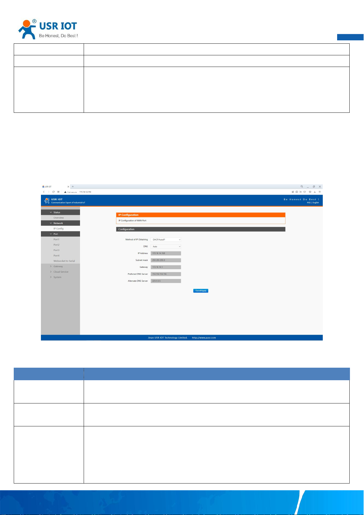
3.2.2. IP settings
You must assign a valid IP address to the USR-N5X0 before it will work in your network environment. The IP address must be unique
within the network. If the device is connected to the Internet and should connect to other servers over the Internet to get some
services such as Network Time Protocol (NTP) server, you will need to configure the DNS server in order to be able to resolve the host
name of the NTP server. The detailed description of the configuration parameters on this interface is shown in table 12.
Fig. 28 Network web page
Table 12 Network configuration list
Your TrustWorthy Industrial IoT Partner www.pusr.com
Page 31
User Manual
30
of addresses: A, B, and C.
Subnet mask
The mask is a 32-bit number corresponding to an IP address. Some of these numbers are 1, and the
others are 0. The mask can divide the IP address into two parts: the subnet address and the host address.
The part of the IP address corresponding to the 1 bit in the mask is the subnet address, and the other bits
are the host address. The mask for class A addresses is 255.0.0.0, the mask for class B addresses is
255.255.0.0, the mask for class C addresses is 255.255.255.0.
Gateway
The default gateway in the host is usually called the default route. The default route (Default route) is the
route chosen by the router when no other route exists for the destination address in the IP packet. All
packets whose destination is not in the router's routing table will use the default route.
DNS
The IP address of the DNS server. DNS Server part is where you can specify the IP Address of your
Preferred DNS (Domain Name Server) and Alternate DNS. When the device uses a static IP address, the
user is required to fill in this item, 8.8.8.8(Google) will be a good choice. If a specific DNS server is not
used, the default gateway IP address is generally sufficient.
Parameter Item
Description
The configuration will save to flash memory after clicking Save button. All configurations take effect after a system reboot.
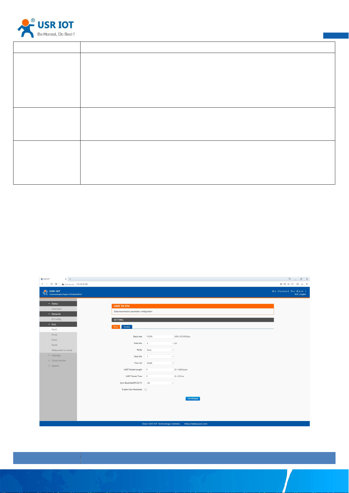
3.2.3. Serial port settings
The serial port module includes: serial port parameter configuration, network parameter configuration. The main function of the serial
device server is to carry out two-way transparent transmission of standard serial bus data (RS-232, RS-485, RS-422) and standard
Ethernet data supporting TCP/IP protocol to solve common serial equipment Networking problems on the Internet. The Port
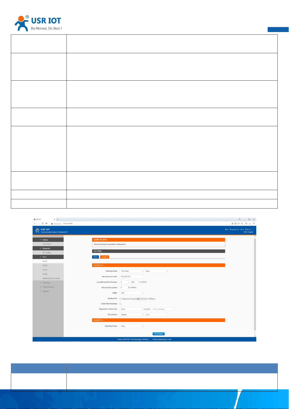
configuration page can configure the parameters of the serial port and socket, as shown in Fig.29. Details on work mode connectivity
protocols and its settings of N5X0 series are given in Chapter 4 Operation modes, this section will only focus on the part of
parameter description. The description of the configuration parameters on this interface is shown in table 13 and table 14.
Fig. 29 Serial port configuration web page
Your TrustWorthy Industrial IoT Partner www.pusr.com
Table 13 Serial settings list
Page 32
User Manual
31
Baud rate
This sets the port’s data transfer speed. Choices are from 600—921600. Set this to match the baud rate
setting of the connected device. Default is 115200.
Data bits
This sets the number of bits used to transmit one character of data. Choices are: 7 and 8. Set this to
match the data bit setting of the connected device. Default is 8 (which is the default for the majority of
serial devices).
Parity bits
This bit checks the integrity of the transmitted data. Choices are: None, Odd, Even, Space, Mark. Set this
to match the parity setting of the connected device. Default is None (which is the default for the majority
of serial devices).
Stop bits
This indicates that a character has been transmitted. Set this to match the stop bit setting of the
connected device. Choices are: 1 and 2. Default is 1 (which is the default for the majority of serial devices).
Flow control
This allows you to choose how the data flow will be controlled. Choices are: (No Flow Control), RTS/CTS
(Hardware Flow Control), or Xon/Xoff (Software Flow Control). Set this to match the flow control setting of
the connected device. Default is None. If Xon/Xoff is selected, the Xon and Xoff characters are 0x11 for
Xon and 0x13 for Xoff. Note that these are hexadecimal numbers of ASCII characters (i.e., 0x11 = ‘1’ and
0x13 = ‘3’).
Serial mode(N5X0
models)
Click the drop-down menu to select the type of serial interface for the port. Choices are RS-232,RS-422,
RS-485 (2 Wire).
Packing time
Click the option to sent pack immediately by interval.
Packing length
Click the option to sent pack immediately by size.
Parameter Item
Description
Work mode
USR-N5X0 series supports 5 different operation Modes which are TCP Server, TCP Client, and UDP,HTTP
client and websocket. The operation Mode describes the role of the device and the connection between
The configuration will save to flash memory after clicking Save button. All configurations take effect after a system reboot.
Fig. 30 Socket configuration web page
Table 14 Operation modes settings list
Your TrustWorthy Industrial IoT Partner www.pusr.com
Page 33
User Manual
32
the device and other remote devices in the network which would like to communicate with serial device
on N5X0’s COM port.
Maximum socket no.(TCP
server only)
This option specifies the maximum number of remote devices/clients (with maximum of 16 clients,except
N580 with 8) that can be connected to the serial device on this COM port.
Local port
This option specifies the port number that the TCP/UDP server should listen to. It is also used by the
remote TCP/UDP client to connect to the TCP/UDP server. The default local port is 23. You can enter
different port numbers in this option.
Remoter server addr.
Please specify the IP address of the TCP/UDP server program on the remote host in this field. This should
match the IP settings of the TCP/UDP server program.
Remote port
Please specify the port number of the TCP/UDP server program on the remote host in this field. Once
again, this should match the IP setting of the TCP/UDP server program.
Timeout
reconnection(TCP/UDP
client)
The default is disable. If you want to keep connection continually, you can disable it. Data idle Time is the
time period for which the device waits for data. If the USR-N5X0 Series does not receive data during
established idle time(timeout), the USR-N5X0 Series will disconnect temporarily. When the data comes
in, it will reconnect automatically. Users do not need to reconnect.
Modbus polling
This option is selected when multiple modbus maters from Ethernet are polling the same serial port.
Each serial port supports up to 16 simultaneous TCP connections allowing hosts to simultaneously
transmit/receive data to/from the same serial port,USR-N5X0 Series processes the data in the order
arrived. The serial device server determines the end of the serial acknowledgement through a response
timeout.
Response timeout
If the Modbus device does not receive a response within the time specified here, the communication
times out. Valid settings are from 10 – 9999ms.
Modbus exception
This option is used to enable modbus exception checking. If selected, error messages (TCP exception
codes) are generated if a problem (such as a message timeout) should occur during Modbus operations.
SSL protocol
Choose TLS/SSL data encryption protocol version
Socket B
Socket B supports 2 different operation Modes which are TCP Client, and UDP client, this socket is closed
by default.
The configuration will save to flash memory after clicking Save button. All configurations take effect after a system reboot.
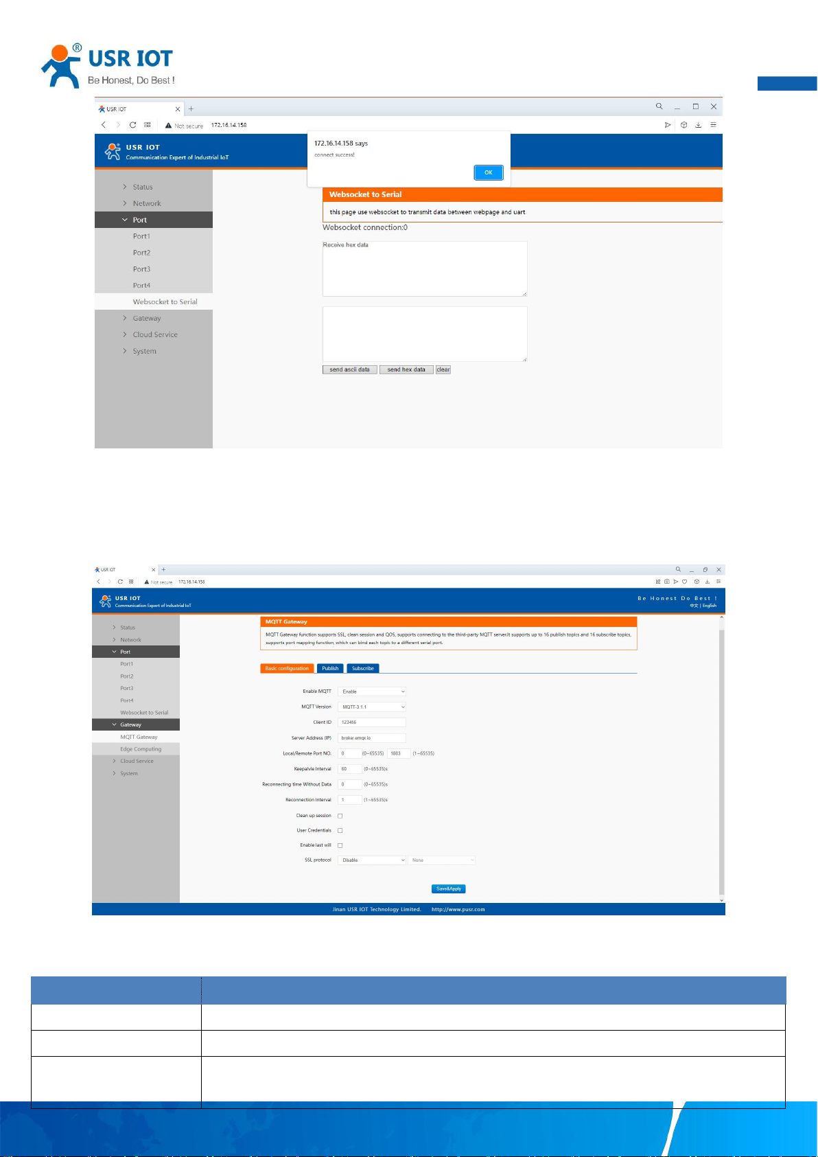
3.2.4. Websocket server
This function is that the serial server acts as a WebSocket server, and transparently transmits the data received by the serial to the
webpage in hexadecimal or ascii format. The WebSocket server can also send data to the serial device at any time.
Your TrustWorthy Industrial IoT Partner www.pusr.com
Page 34
33
Fig. 31 Websocket server
Parameter Item
Description
Enable
Turns MQTT gateway on or off.
Version
Select the mqtt protocol version. V3.1 and V3.1.1 are supported.
Client ID
The client ID defined the identifier of the N5X0 Gateway.
The IDs of the various MQTT clients have to be unique for the respective MQTT Broker. If two MQTT
User Manual
3.2.5. MQTT gateway
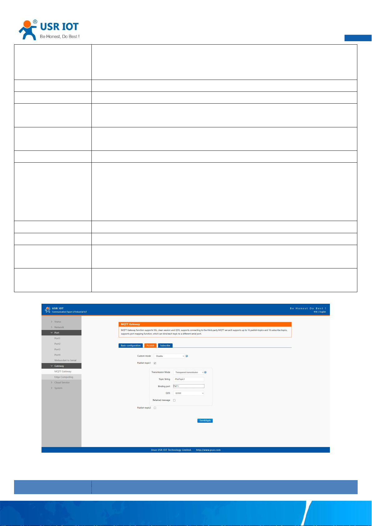
If you enable MQTT Broker as your northbound connection, the N5X0 will be configured as MQTT Client. In Client mode, you can
setup MQTT broker basic settings, general topic settings, TLS secure transmission, last will message, and advanced settings.
Fig. 32 MQTT connection profiles
Table 15 MQTT basic setting
Your TrustWorthy Industrial IoT Partner www.pusr.com
Page 35
User Manual
34
clients are using an identical ID, the connections of theses clients to the MQTT Broker are
disconnected. For an individual client, there is no way to find out whether a specific client ID is already
used by another client or not.
Server address
IP address or hostname of an MQTT broker.
Remote Port
Port number of the MQTT broker.
Keep alive interval
The Keep Alive is a time interval measured in seconds. It is the maximum time interval that the broker
permits between when a client finishes sending one MQTT packet and starts to send the next.
Re-connection time
Automatic reconnection when there are not data flow in the MQTT session in the setting time. If the
time is set 0, this function does not take effect.
Interval
Automatic reconnection interval after a fail network connection.
Clean session
Valid only for Qos1 and Qos2. When the clean session is checked, the client does not want a persistent
session. If the client disconnects for any reason, all information and messages that are queued from a
previous persistent session are lost.
When the clean session is unchecked, the broker creates a persistent session for the client. All
information and messages are preserved until the next time that the client requests a clean session.
User name
Username for authentication to the MQTT broker.
Password
Password for authentication to the MQTT broker.
Last will
The last will message is part of the Last Will and Testament (LWT) feature of MQTT. The will message
notifies other clients when a client disconnects ungracefully.
SSL/TLS
If you use a TLS connection, click the SSL/TLS tab, select Enable SSL/TLS, and then set
the Protocol parameter to TLSv1.2
Parameter Item
Description
Fig. 33 Topic to publish
Your TrustWorthy Industrial IoT Partner www.pusr.com
Table 16 Publish message setting
Page 36

User Manual
35
Transmission mode
Transparent transmission, just as its name implies,the gateway does not process any data, forward the
data directly.
Topic distribution,in this mode users should define a topic name when configuring the topic. After
receiving serial port data, the device pushes it to the associated topics based on the topic name. Topic
name and payload are separated by comma. For example, topic name, {"message": "Hello from
USR-N510 gateway"} as serial data. Different topics are allowed to have the same topic name. In this
way, data is pushed to all topics with the same topic name.
Custom mode, add topic, Qos(0,1,2), retain(ON,OFF) message before payload. After receiving the serial
data, N510 publishes the payload of the corresponding topic to cloud according to rules. This method
can be used to publish any topic at any time. For example, awsiot/test,0,ON,{"message": "Hello
from USR-N510 gateway"} as serial data.
TOPIC string
An MQTT topic is a UTF-8 string that the broker uses to filter messages for each connected client. To
receive messages, the client must subscribe to the topic. A topic can have one or more topic levels.
Each topic level is separated by a slash (Topic Level Separator).
Binding Port
The MQTT topic is bound to the serial port number of the device. Any data from the COM Port1 of the
gateway will send to all the TOPIC it bindings to.
Qos
QoS 0: at most once. In this case, the client publishes a message to the broker only once.
QoS 1: at least once. In this case, when a client publishes a message to the broker, the client expects
the broker to acknowledge whether or not a client has received the message. If the publisher does not
receive acknowledgement from the broker within a preset time interval, it will republish the message
again and again until acknowledgment is received.
QoS 2: exactly once. The MQTT protocol uses the confirmation of confirmations to ensure that a
message is delivered exactly once.
Retained message
By setting the Retain flag the MQTT Broker is instructed to save the most recent data value for the
topic. Data values without Retain flag are only transferred from the MQTT Broker to those MQTT
Subscribers that are registered at the broker and have subscribed to the appropriate topic in the
moment when sending the data to the broker.
Your TrustWorthy Industrial IoT Partner www.pusr.com
Page 37
36
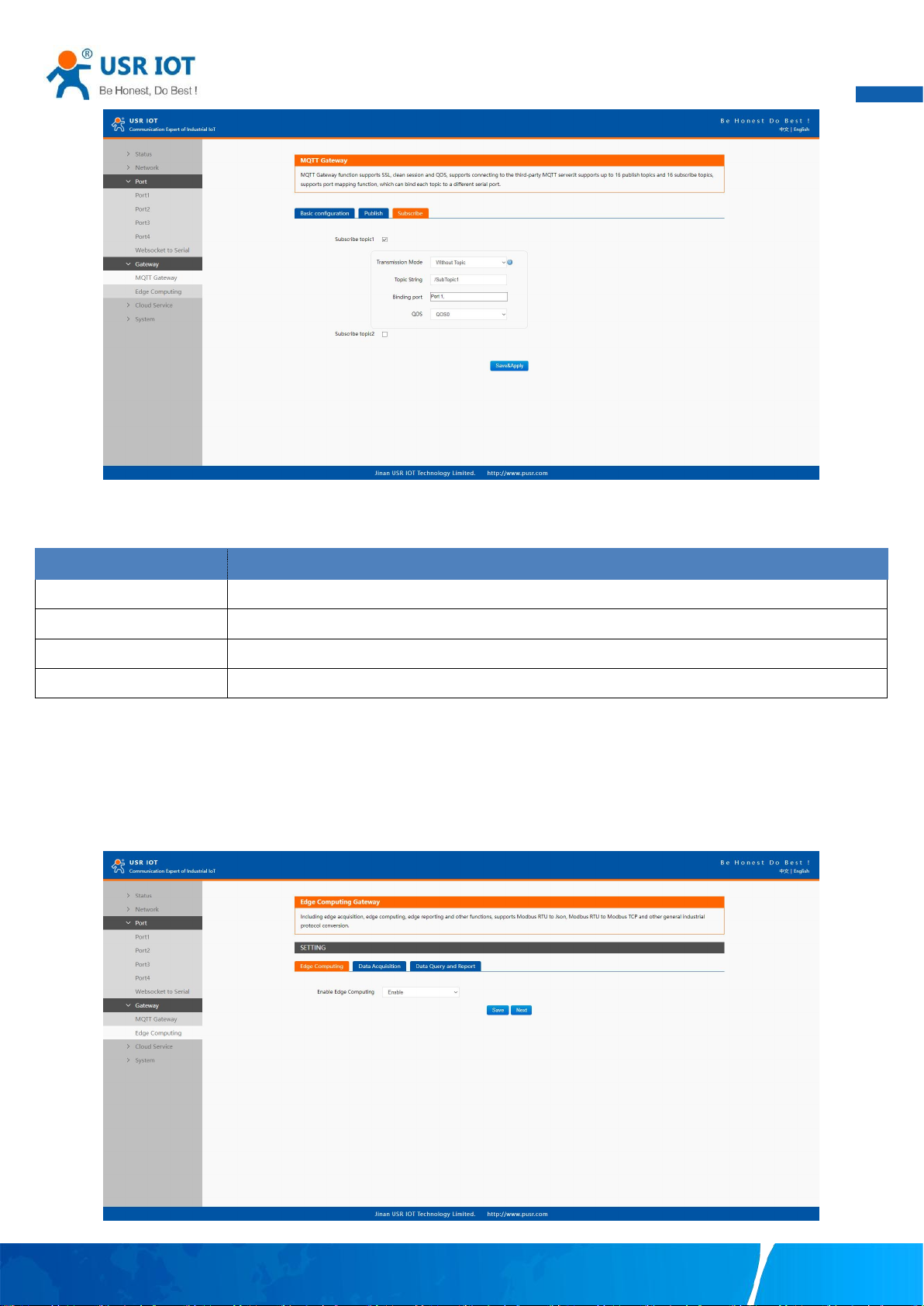
Fig. 34 Topic to subscribe
Parameter Item
Description
Transmission mode
The data printed to the serial port can be set whether to carry the Topic
Topic string
Same to Table 16
Binding port
Same to Table 16
QoS
Same to Table 16
Table 17 Subscribe message setting
User Manual
3.2.6. Edge computing
The N5X0 supports southbound fieldbus protocols of Modbus RTU protocols. It also supports northbound MQTT/ Cloud protocols of
MQTT Broker, TCP/UDP/HTTP in socket, AWS IOT, and Alibaba Cloud IoT Platform. The N5X0 fulfills a different role on each of its
sides. Each role is determined by your devices' settings. Therefore, set the role of each of your devices correctly.
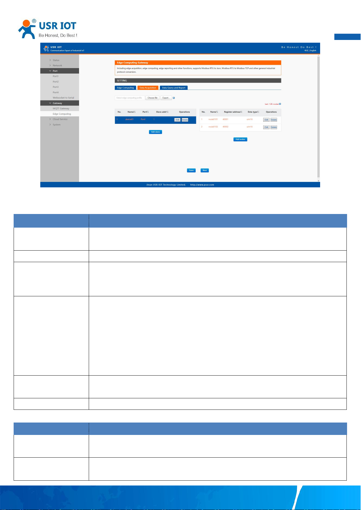
Fig. 35 Edge computing enabled
Your TrustWorthy Industrial IoT Partner www.pusr.com
Page 38
37
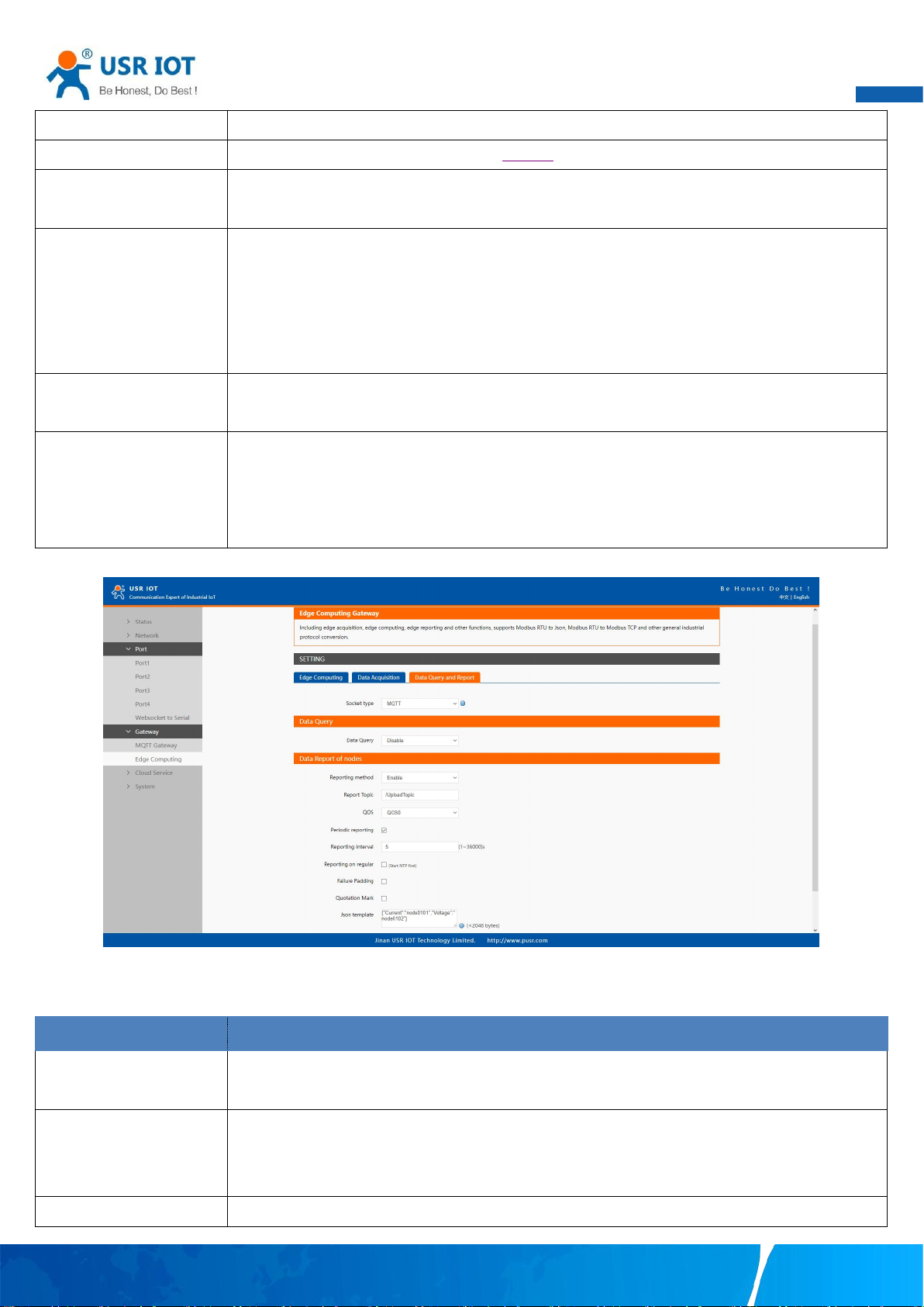
Fig. 36 Modbus slaves and datapoints configuration
Parameter Item
Description
Device name
The Modbus slave device identifier, which is unique for the current gateway. The device name must be
less than 30 characters in length, and can contain letters, digits, underscores (_).
COM Port
Which serial port the modbus slave device connected to. Select an option from the drop-down list.
Slave address
Slave ID. Each slave in a network is assigned a unique identifier ranging from 1 to 255. When the
master requests data from a slave, the first byte it sends is the Slave ID. When set to 0, the slave will
respond to requests addressed to any ID.
Polling interval
The interval at which data is collected. Modbus is a communications protocol with half-duplex
transmission. Gateways send requests to collect data from devices. Therefore, you must specify the
data collection interval. The unit is millisecond.
If 60 milliseconds is required to collect the data of each property, the total time required to collect the
data of all properties is calculated as follows:
Total required time = Time required to collect the data of each property (60 ms) × Number of
properties for the slave device.
Modbus address mapping
This function is usually combined with register mapping to realize a single modbus command query in
data query.
Merger collection
This function is used when the register address of many data points are sequential
Parameter Item
Description
Data point name
Identifier of the data point, which must be unique for the gateway. The name must be 1 to 30
characters in length and can contain letters, digits, and underscores (_).
Modbus function code
The Modbus RTU master supports the following Modbus functions: 1 Read Coils, 2 Read Discrete
Inputs,3 Read Multiple Holding Registers, 4 Read Input Registers.
Table 18 Modbus RTU poll configuration
User Manual
Table 19 Data point(node) configuration
Your TrustWorthy Industrial IoT Partner www.pusr.com
Page 39
User Manual
38
Register address
The address of the register from which data will be read.
Data type
Defines how read data will be stored. See table 26.
Response timeout
If the Modbus device does not receive a response within the time specified here, the communication
times out. Valid settings are from 10 – 65535ms.
Data report
The trigger of reporting data. Valid values:
On Change: The report is triggered if the collected data changes. You can use a tolerance to only log
the data point if the value changes more than X amount.
Interval: Collect the variable data at the poll interval and report the data at the specified report interval.
Timer: Collect the variable data at the poll interval and report the data at the regular time.
Register address mapping
This function is usually combined with modbus address mapping to realize a single modbus command
query in data query.
Formula
Modbus register store only whole numbers. For this reason a scale factor often needs to be applied.
For example a modbus register with a temperature value may read as 723 and a multiplier of 0.1 need
to be applied to get the correct value of 72.3 in the SCADA system,the formula is %s*0.1. If the data
type is a Float then the multiplier is not needed. This computation supports +, -, * and / operators.
Parameter Item
Description
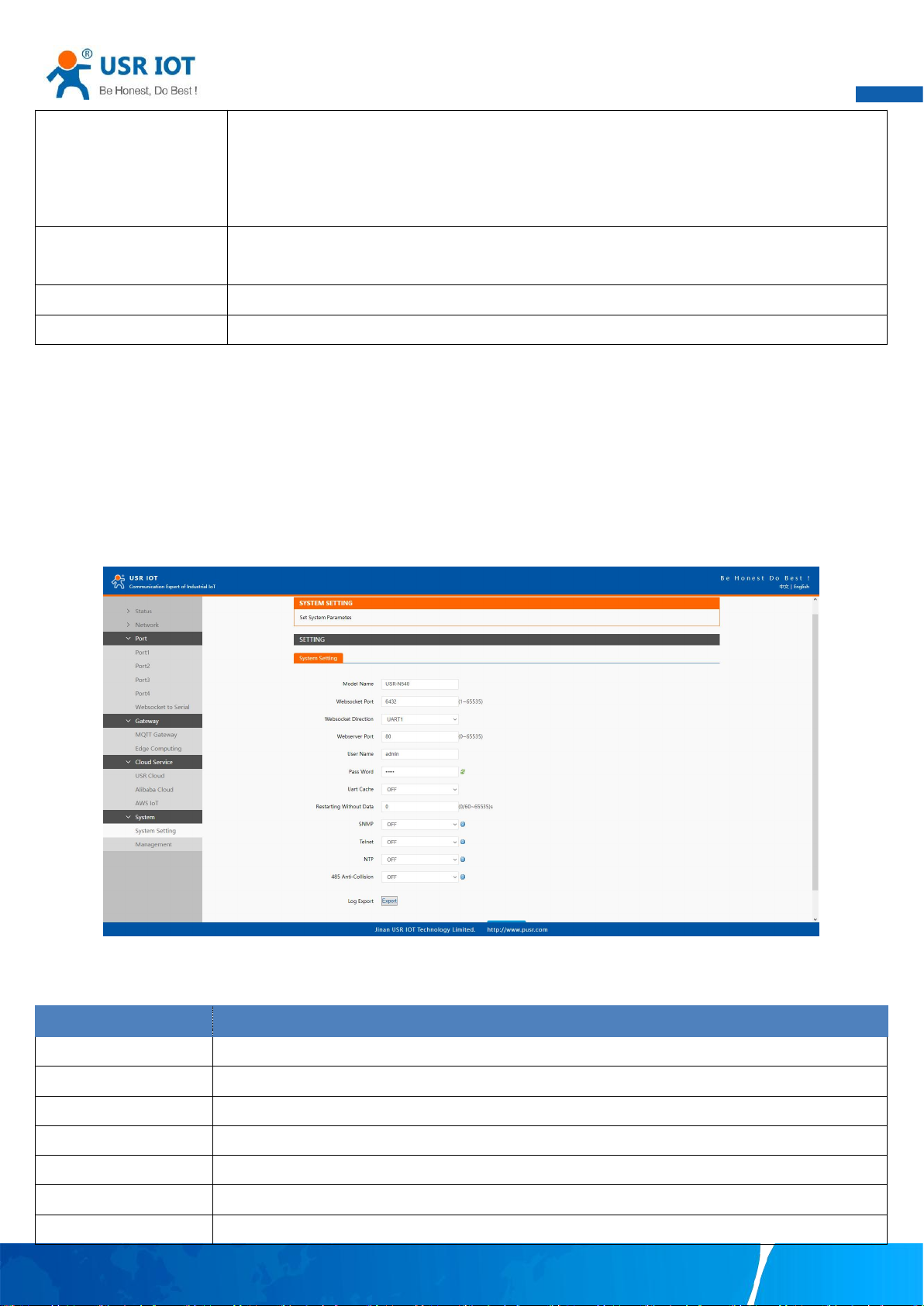
Communication channel
Select the channel in the socket type. You can choose TCP/UDP or HTTP in socket A of each serial
port, or MQTT you have added.
Data query
Query type. You can choose Modbus RTU, Modbus TCP or JSON. Users can send the right format
query command from remote modbus master or MQTT publisher to the N5X0 gateway. The data is
retrieved from the device's cache of corresponding modbus instructions.
Data report
The trigger of reporting data. Valid values:
Fig. 37 Transport channel and formatting
Table 20 Data Query and report
Your TrustWorthy Industrial IoT Partner www.pusr.com
Page 40
User Manual
39
On Change: The report is triggered if the collected data changes. You can use a tolerance to only log
the data point if the value changes more than X amount.
Interval: Collect the variable data at the poll interval and report the data at the specified report interval.
Timer: Collect the variable data at the poll interval and report the data at the regular time.
Failure padding
Exception handling. Any data point did not get the response in response timeout will be filled with this
string as key value into the template.
Quotation mark
Numeric values are quoted. It does not affect a string.
Json template
The payload format. Users can custom which data points should report to the server.
Parameter Item
Description
Module name
The name of the device, up to 32 characters,can’t be null
Websocket port
Websocket server listen port NO. Range 1-65535
Websocket direction
Click the drop-down menu to select websocket mapping direction: UART or Log.
Webserver port
Web server listen port NO. Range 1-65535
User name
The user name of web console and can be modified. up to 16 characters,can’t be NULL
Password
The password of web console and can be modified. up to 16 characters,can’t be NULL
UART cache
Click the option to enable serial buffer. By default, N5X0 will empty its serial buffer when a new TCP
3.2.7. Cloud service
Please refer to “USR-N5X0 Quick Start Guide with AWS IoT” for detail.
Please refer to “USR-N5X0 Quick Start Guide with PUSR cloud” for detail.
3.2.8. System setup
This system setting tab includes several system level settings, such as device name, websocket, system log, user name and password.
Most of these settings are optional.
Fig. 38 System settings
Table 21 System settings list
Your TrustWorthy Industrial IoT Partner www.pusr.com
Page 41
User Manual
40
connection is established. This means that the TCP application will not receive buffered serial data during
a TCP link breakage. To keep the serial data when there is no TCP connection and send out the buffered
serial data immediately after a TCP connection is established, you can disable this option.
Restarting without data
This function is used for the serial device server without any data transmission or reception for a long
time, and the serial server automatically restarts. If the restart time is set between 0 and 59 seconds, this
function does not take effect. Only when the time is set to be greater than or equal to 60 seconds, the
restart function of the device without data will take effect.
The configuration will save to flash memory after clicking Save button. All configurations take effect after a system reboot.
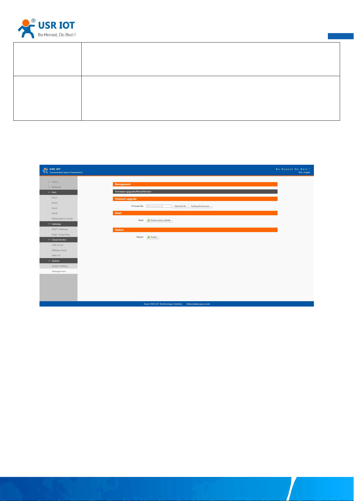
In management page users can perform some system operations on the N5X0 series serial server, including restarting, restoring
factory configuration, and upgrading. It is recommended that users use it with caution. Improper operation may damage the serial
server.
Fig. 39 Module management
Restart
This function is used to restart the USR-N5X0 series serial server by software. Before the serial server is completely restarted, the
device does not work and cannot forward any data packets. This restart is different from the hardware reset of power-on restart, but
the serial server system software is reset, just like the "warm restart" of the windows operating system. Once a new setting is changed,
you can use the Save function to accept the changes. You will need to reset the device to save the settings to flash memory. Click on
"restart" Button, the page pops up a prompt box, click "OK".
Restore factory defaults
This function is used to restore the USR N5X0 serial server to the factory settings and automatically restart the serial server at the
same time. Before the serial server restarts successfully, the serial server does not work and cannot forward any data packets. This
function is to restore the factory default configuration value once the user sets the wrong parameter and causes the serial port server
to work abnormally. Click the "Restore factory defaults" button, and a prompt box will pop up on the page. Click "OK".
Firmware upgrade
USR IoT continually upgrades its firmware to add new features and optimize performance. Please contact the sales to obtain the
latest version of the firmware. Before upgrading the firmware, please make sure that the device has a reliable power source that will
Your TrustWorthy Industrial IoT Partner www.pusr.com
Page 42
User Manual
41
not be powered off or restarted during the firmware upgrading process(please be patient as this whole process might take up to 1 -2
minutes).
Copy the new firmware file to your local computer. Note that the firmware file is a binary file with “.bin” extension. Before updating
the firmware, make sure that your host’s Network domain is as same as the serial device server.
Next, click “Select the file” button as shown in Figure to find and choose the new firmware file. Then, click "Flashing the firmware"
button to start the firmware upgrade process. After the progress bar in the page is read, the serial server software upgrade is
completed. Please wait until the uploading process is finished (the amount of time varies depending on the equipment used).
Finally, the device will then proceed to restart itself. In most cases, you might require to re-configure your device.
3.3. Configuration software
3.3.1. Discovering your device server
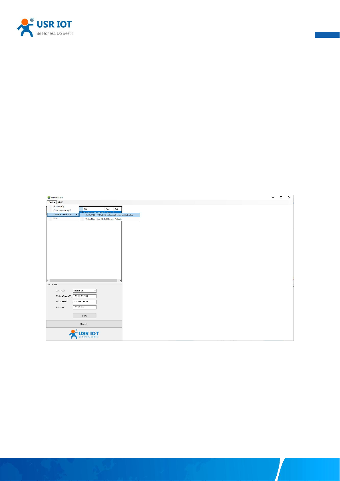
After you start EthernetTool software, if the USR-N5X0 Serial Device Server is already connected to the same gateway as your PC, the
device can be accessed via broadcast packets. Users can search all the USR-N5X0 Series device servers on the network and show
them on the Serial Device Server List Area of the utility. Please select the right Ethernet adapter if you did not see any serial device
server.
Fig. 40 Searching serial device server
3.3.2. Network setting
Sometime the USR-N5X0 device might not be in the same subnet as your PC, therefore, you will have to use this utility to locate it in
your environment. To configure each device, first click to select the desired device (default IP:192.168.0.7) in the list of configuration
utility, and then change the IP address to avoid any IP address conflict with other hosts on your LAN, save your change.
Your TrustWorthy Industrial IoT Partner www.pusr.com
Page 43
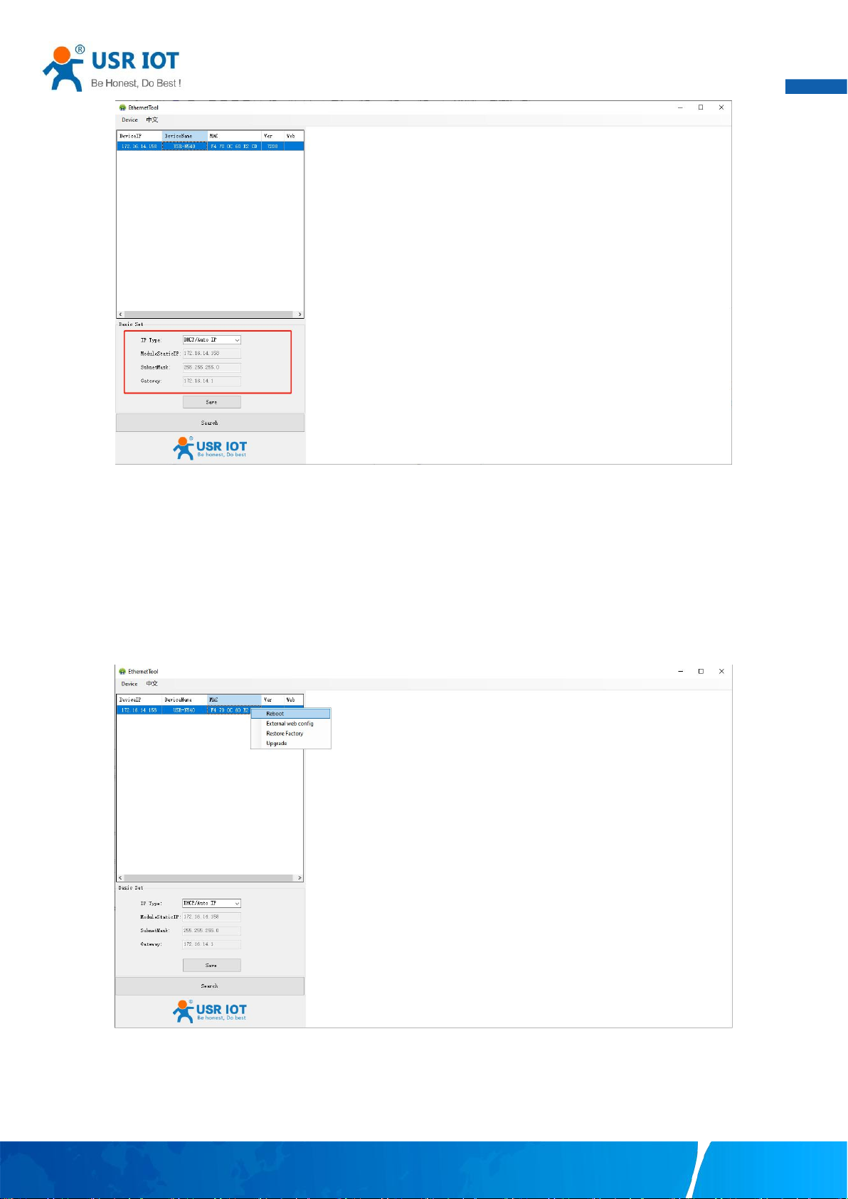
42
Fig. 41 Changing network settings
User Manual
3.3.3. Reboot the device
This function is available to allow you to reset the serial device server. The function disconnects both the ethernet and serial
connections. The function also allows the serial device server to save new configuration settings to flash memory. To reset the device:
1. Right-click a desired device to display the settings menu.
2. Select Reboot.
Press the Reboot button and the system will give a reset response.
Fig. 42 Reboot the device
3.3.4. Restore to factory default settings
The configuration utility provides the function to restore the serial device server to factory default settings. If you really want to
restore the serial device sever to factory default settings, please click restore factory button to continue.
Your TrustWorthy Industrial IoT Partner www.pusr.com
Page 44
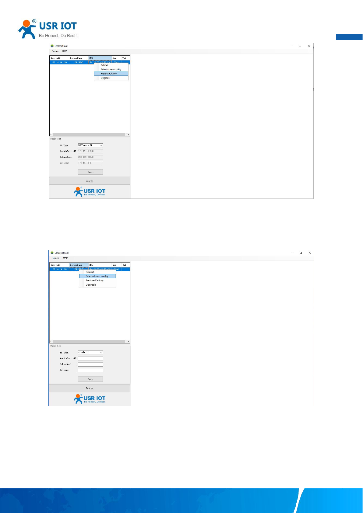
43
Fig. 43 Restore factory defaults
User Manual
3.3.5. Open web server
Users can visit the web server of serial device server conveniently with configuration tool. Select the device you want to visit and right
click,then click External web config ,you will open the web server with default browser such as Google Chrome.
Fig. 44 Open webpage in browser
3.4. AT command
In order to reduce the length of this document, we have organized this section into a special document. Please refer to “USR Cortex
M7 series serial to Ethernet device server AT command manual” for detail.
Your TrustWorthy Industrial IoT Partner www.pusr.com
Page 45
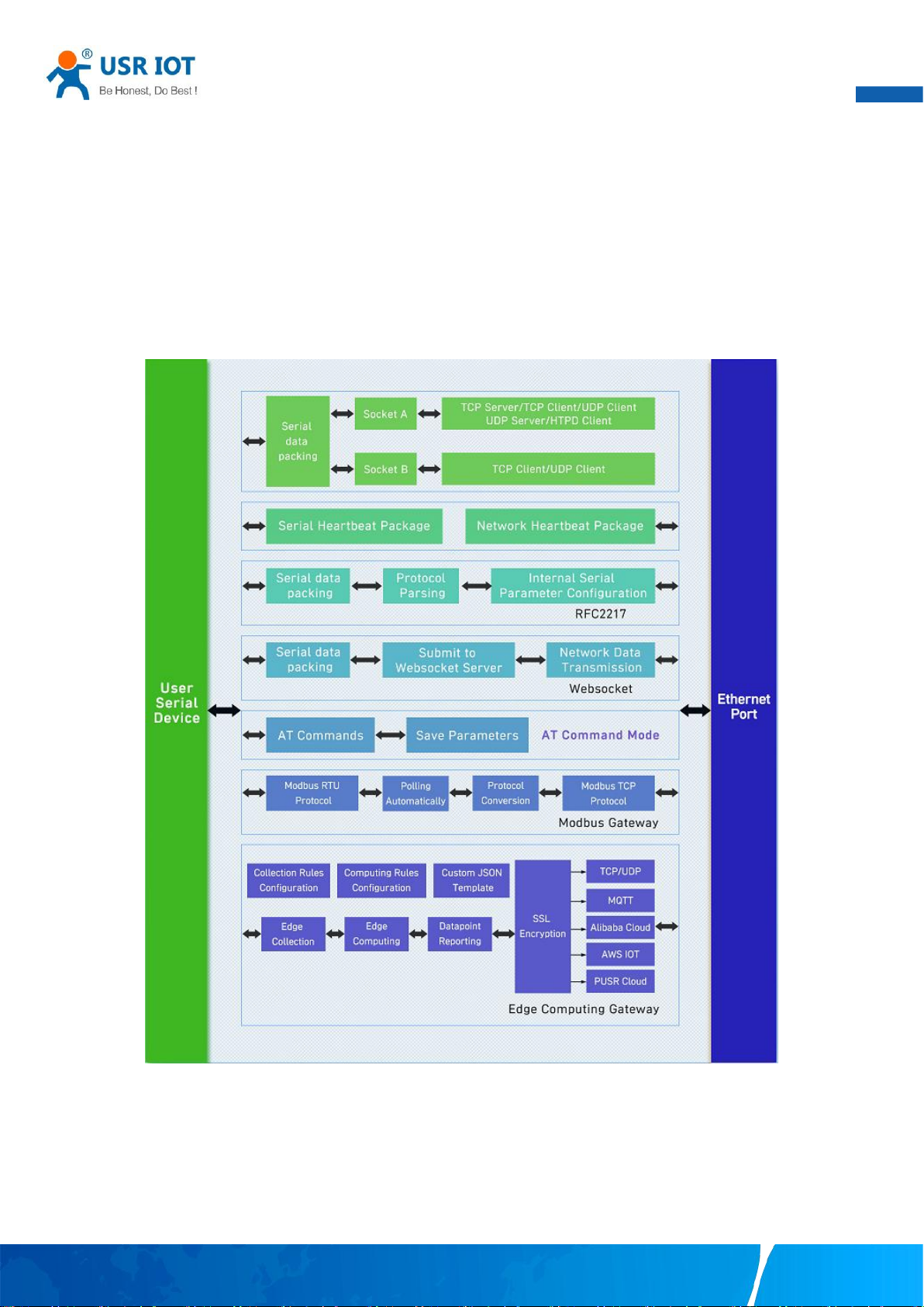
User Manual
44
4. Operation modes
The USR-N5X0 Series provides various operations: TCP Server/ Client mode, UDP mode, HTTP mode and Websocket mode. The
main difference between the TCP and UDP protocols is that TCP guarantees delivery of data by requiring the recipient to send an
acknowledgement to the sender. UDP does not require this type of verification, making it possible to offer speedier delivery. UDP also
allows unicast or multicast of data to only one IP or groups of IP addresses. Detailed descriptions of each operation are provided in
following sections. After choosing the proper operation mode in this chapter, refer to Chapter 3 for detailed configuration
parameter definitions. Because the V2 firmware contains all the function of V1 firmware, we describe the configuration in V2 firmware
as illustration in this chapter, users of V1 version can refer to it for reference.
Fig. 45 Block diagram
4.1. TCP Server
4.1.1. Properties
In TCP server mode, the TCP connection is initiated from the host to the USR-N5X0 Series device server. This operation mode
supports a maximum of 16 (except 8 for N580) simultaneous connections for each serial port on an device server from a single or
multiple hosts. After the connection is established between the serial device server and the remote host computer (remote TCP
Your TrustWorthy Industrial IoT Partner www.pusr.com
Page 46
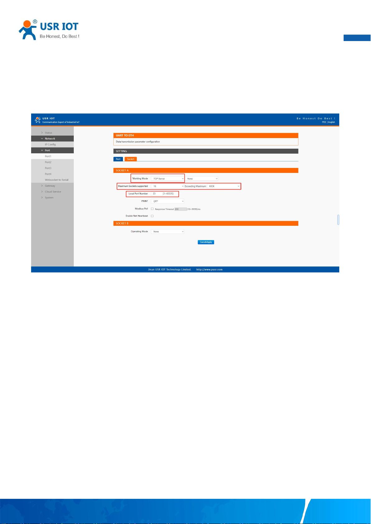
User Manual
45
client) , data can be transmitted in both directions. The COM port on the device will forward requests from all remote connected
hosts(Ethernet) to the serial device immediately and reply to all remote connected hosts once it receives data from the serial
device(RS-232/RS-422/RS-485).
The default operation mode of USR-N5X0 is the TCP Server mode. Fig.46 shows an example of configuration setting for TCP Server
working mode under the Port1 socket tab. You can configure other serial ports in the same way. There are additional connection
settings that can be configured as shown in Fig.46.
Fig. 46 TCP server work mode
Please follow the following steps to configure connection settings of the work mode for PORT1 port.
1. Click on the “Port1” tab on the menu frame on the left side of Web UI to go to Port1 page as shown in Fig.46.
2. For Serial Settings on the Port configuration page, please go to Section 3.2.3.
3. Click on the Socket tab in this page, select TCP Server in the working mode options. The local ports of different serial ports must
be different. After receiving network data, the device determines which serial port the data is sent to based on the local port. For
example, the default port number of the first serial port (Port1) is 23, the default port number of the second serial port (PORT2) is 26,
and so on.
4. After finishing configuring the working Mode, please scroll down to the bottom of the page and click on "Save & Apply" button to
save all the changes that you have made. All configurations take effect after a system reboot.
Fig.47 shows an example of test in this mode. By selecting the TCP Server work mode, a TCP client program on a remote host
computer should be prepared to connect to USR-N5X0. Server IP is IP address of USR-N5X0, server port is local port of USR-N5X0. In
this case, IP address of USR-N5X0 is 172.16.14.12.
Your TrustWorthy Industrial IoT Partner www.pusr.com
Page 47
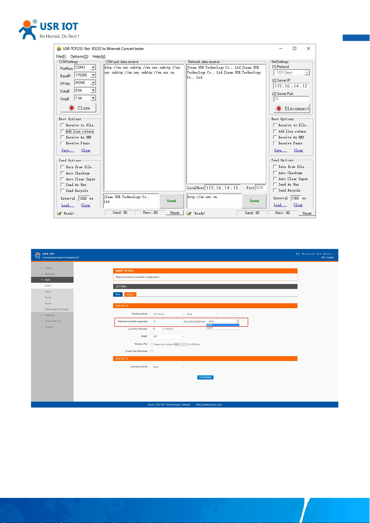
User Manual
46
4.1.2. Multihost setting
Fig. 47 Host initiating TCP connection
Fig. 48 Maximum socket connection
Maximum connection is usually used when the user needs to receive data from different hosts simultaneously. The factory default
allows 8 connection at a time. This option specifies the maximum number of remote devices/clients (with maximum of 16 clients) that
can be connected to the serial device on this COM port. And users can define the behavior when the connection established exceed
the maximum.
Kick: when the connection exceeds the maximum number, actively kick out the oldest connection(first in first kick out).
Keep: when the connection exceeds the maximum number, keep the old connection and reject new connections.
Your TrustWorthy Industrial IoT Partner www.pusr.com
Page 48
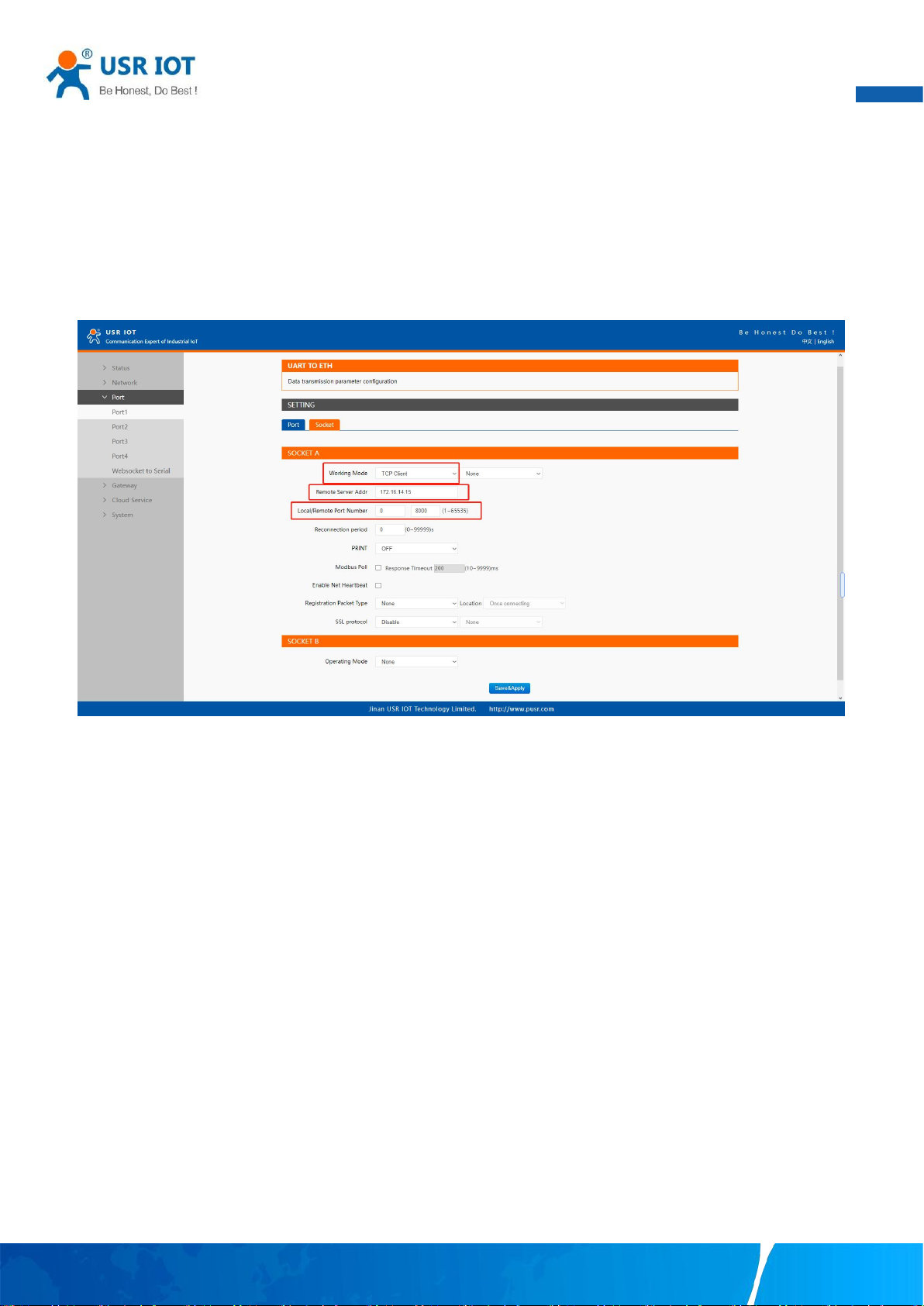
User Manual
47
4.2. TCP Client
4.2.1. Properties
When the working mode of this device is TCP Client, the remote device must work in TCP Server mode, and its IP address and port
number must be configured, which can be configured in the corresponding options of the network connection. The local port number
can be ignored and no configuration is required. USR-N5X0 supports SSL (TLS v1.0 or v1.2) data encryption in this operating mode.
Fig.49 shows an example of configuration setting for TCP Client working mode under the Port1 socket page. You can configure other
serial ports in the same way. There are additional connection settings that can be configured as shown in Fig.49.
Fig. 49 TCP client work mode
Please follow the following steps to configure connection settings of the work mode for PORT1 port.
1. Click on the “Port1” tab on the menu frame on the left side of Web UI to go to Port1 page as shown in Fig.49.
2. For Serial Settings on the Port configuration page, please go to Section 3.2.3.
3. Click on the Socket tab in this page, select TCP Client in the working mode options. Please specify the Destination IP address and
port number of the TCP server program on the remote host. This should match the IP settings of the TCP server program. The default
local port number is 0, N5X0 will assign a random TCP Port.
4. After finishing configuring the working Mode, please scroll down to the bottom of the page and click on "Save & Apply" button to
save all the changes that you have made. All configurations take effect after a system reboot.
Fig.50 shows an example of test in this mode. By selecting the TCP Client operation mode, a TCP server program on a remote host
computer should be prepared to accept a connection request from the device. In this case,Host IP address is 172.16.14.15.
Your TrustWorthy Industrial IoT Partner www.pusr.com
Page 49
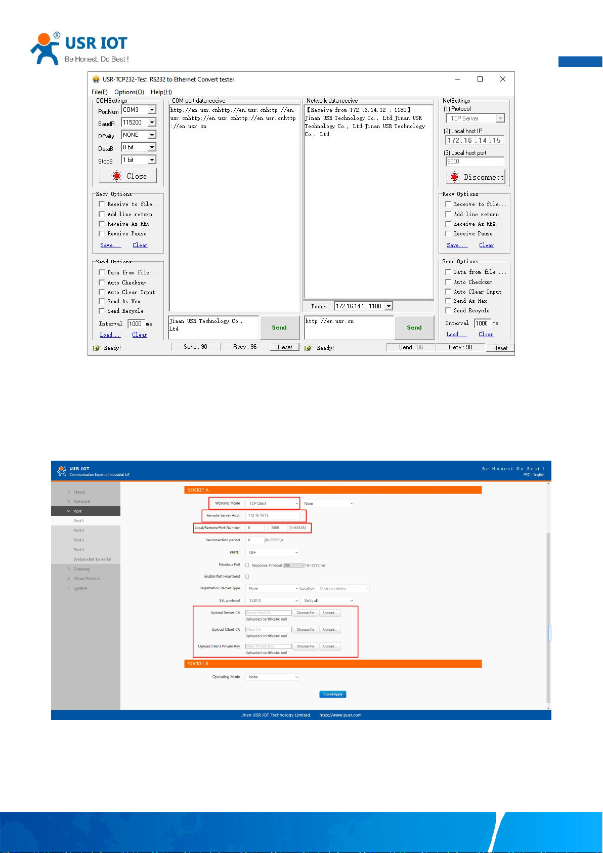
User Manual
48
Fig. 50 N5X0 initiating TCP connection
4.2.2. SSL/TLS
If SSL certificate authentication is enabled on the remote server, user need to configure SSL encryption parameters on N5X0. User
can select TLS1.0 or TLS1.2 version protocol. User can select None certificate Authentication, server certificate authentication and
bidirectional certificate authentication.
Fig. 51 SSL/TLS encryption
4.2.3. transient connection
This connection, called transitory due to its short-lived nature. If the serial port or network port receives none data within the setting
time, the connection will be automatically disconnected. The serial device servers used to send serial device data back to a control
Your TrustWorthy Industrial IoT Partner www.pusr.com
Page 50
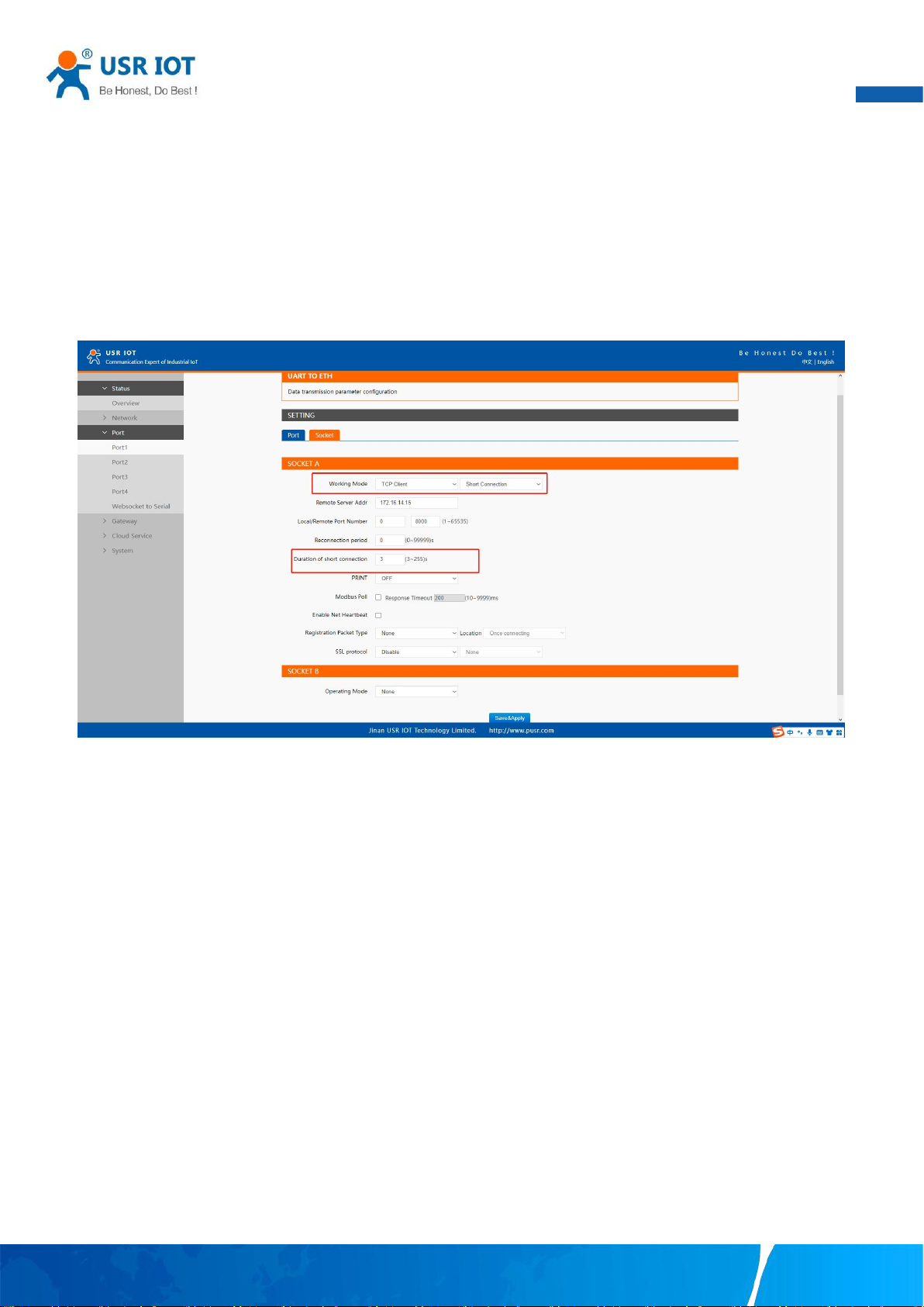
User Manual
49
room or a cloud application need to open a remote connection before they can transfer the serial data. If a large number of serial
devices are connected to the same network, the connection will require many resources in the control room or cloud application. To
handle these large numbers of remote connections properly, serial device servers should support flexible connection control. The
best way to do this is to open a connection only when serial data is received from a device. When the transmission is completed, the
serial device server should immediately close the connection. Without support for flexible connection control, you would need to
spend extra time handling connections at the central site or cloud application.
TCP transient connection is used primarily to save server resources. Fig.52 shows an example of configuration setting for transient
connection in TCP Client working mode under the socket page.
Fig. 52 Transient connection
4.3. UDP Server
4.3.1. Properties
User Datagram Protocol (UDP) is a faster and more efficient transport protocol than TCP but it is a connectionless transport protocol,
it does not guarantee the delivery of network datagram. In UDP mode, you can unicast or multicast data from the serial device to one
or multiple host computers, and the serial device can also receive data from one or multiple host computers. Please beware that even
though UDP provides better efficiency in terms of response time and resource usage, it does not guarantee data delivery. It is
recommended to utilize UDP only with cyclic polling protocols where each request is repeated and independent, such as Modbus
Protocol.
When the working mode of the device is UDP server, the remote device must also work in UDP mode. You only need to specify the
Local Port that USR-N5X0 should listen to. In UDP server mode, serial port data is always sent to the last peer UDP device(IP and port)
that communicates with the USR-N5X0, and the USR-N5X0 can record the IP and port number only after the peer UDP device sends
data to the USR-N5X0 first.
Fig.53 shows an example of configuration setting for UDP Server mode under the Port1 socket page. You can configure other serial
ports in the same way.
Your TrustWorthy Industrial IoT Partner www.pusr.com
Page 51
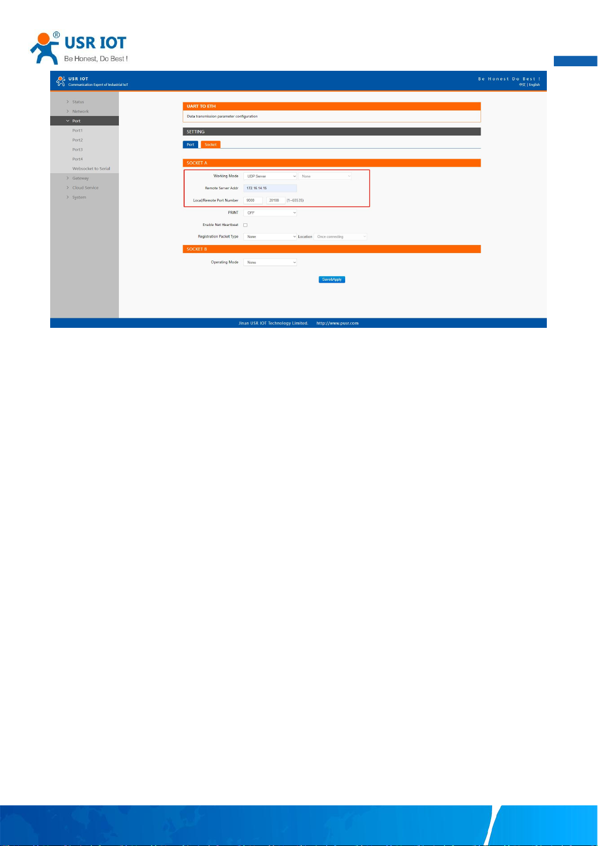
50
Fig. 53 UDP server work mode
User Manual
Please follow the following steps to configure connection settings of the operation mode for PORT1 port.
1. Click on the “Port1” tab on the menu frame on the left side of Web UI to go to Port1 page as shown in Fig.53.
2. For Serial Settings on the Port configuration page, please go to Section 3.2.3.
3. Click on the Socket tab in this page, select UDP Server in the working mode options.
4. Local Port specifies the local port number for UDP server mode on N5X0 which it will be listening to and it can be any number
between 1 and 65535. The local ports of different serial ports must be different. After receiving network data, the device determines
which serial port the data is sent to based on the local port.
5. After finishing configuring the working Mode, please scroll down to the bottom of the page and click on "Save & Apply" button to
save all the changes that you have made. All configurations take effect after a system reboot.
Serial port data is firstly sent to the preset destination IP/domain name and Destination port. After receiving a UDP packet, the system
updates the destination IP address and port number, and sends the data back to the latest IP address and port number. In this case, IP
address of USR-N5X0 is 172.16.14.12, host IP address is 172.16.14.15.
Your TrustWorthy Industrial IoT Partner www.pusr.com
Page 52
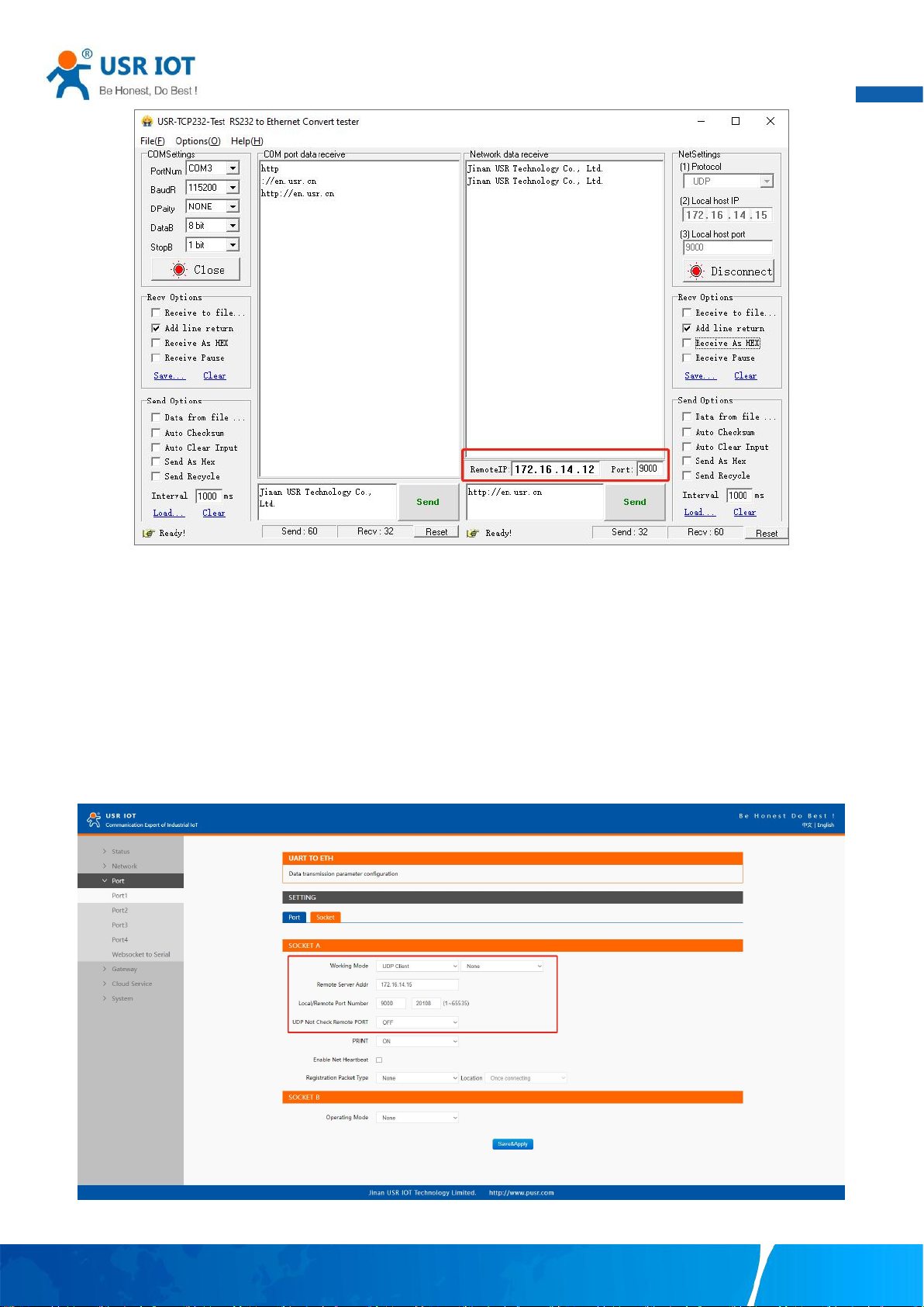
User Manual
51
Fig. 54 UDP transmission test
4.4. UDP Client
4.4.1. Properties
When the working mode of the device is UDP client, the remote device must also work in UDP mode. N5X0 supports remote IP
address and port verification. After verification is enabled(OFF), the N5X0 only communicates with the destination port of the
destination IP address. If the data is not from this channel, the N5X0 will discard the data. If verification is disabled(ON), N5X0 does
not filter the data of the destination IP address and destination port. Fig.55 shows an example of configuration setting for UDP Client
mode under the Port1 socket page. You can configure other serial ports in the same way.
Fig. 55 UDP client work mode
Your TrustWorthy Industrial IoT Partner www.pusr.com
Page 53
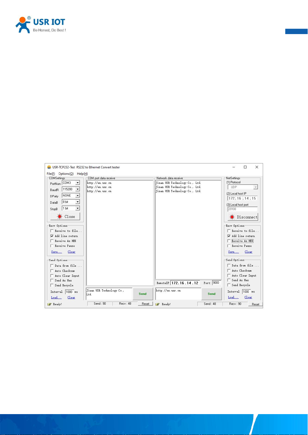
User Manual
52
Please follow the following steps to configure connection settings of the UDP client mode for PORT1 port.
1. Click on the “Port1” tab on the menu frame on the left side of Web UI to go to Port1 page as shown in Fig.55.
2. For Serial Settings on the Port configuration page, please go to Section 3.2.3.
3. Click on the Socket tab in this page, select UDP Client in the working mode options.
4. Please specify the Destination IP address and port number of the UDP program on the remote host. Local Port specifies the local
port number which socket A will be listening to and it can be any number between 1 and 65535. The local ports of different serial
ports must be different. After receiving network data, the device determines which serial port the data is sent to based on the local
port. Note that typically the port number that is larger than 1024 is recommended to avoid conflicting with the well-known port
numbers. You should match this setting with the remote UDP program. Note that this number is usually called destination port in the
remote UDP program.
5. After finishing configuring the working Mode, please scroll down to the bottom of the page and click on "Save & Apply" button to
save all the changes that you have made. All configurations take effect after a system reboot.
Fig.56 shows an example of test in this mode. In this case, IP address of USR-N5X0 is 172.16.14.12, host IP address is 172.16.14.15.
Fig. 56 UDP client test
4.4.2. UDP multicast
UDP also allows multicasting of data to groups of IP addresses. A multicast is a packet sent by one host to multiple hosts. In multicast
mode, each host that belongs to a specific multicast group will receive multicast packets for that group. For a host to be configured
as a multicast receiver over the Internet, the must inform the routers on its LAN. The Internet Group Management Protocol (IGMP) is
used to communicate group membership information between hosts and routers on a LAN. The USR-N5X0 Series supports IGMP
version 2.
Your TrustWorthy Industrial IoT Partner www.pusr.com
Page 54
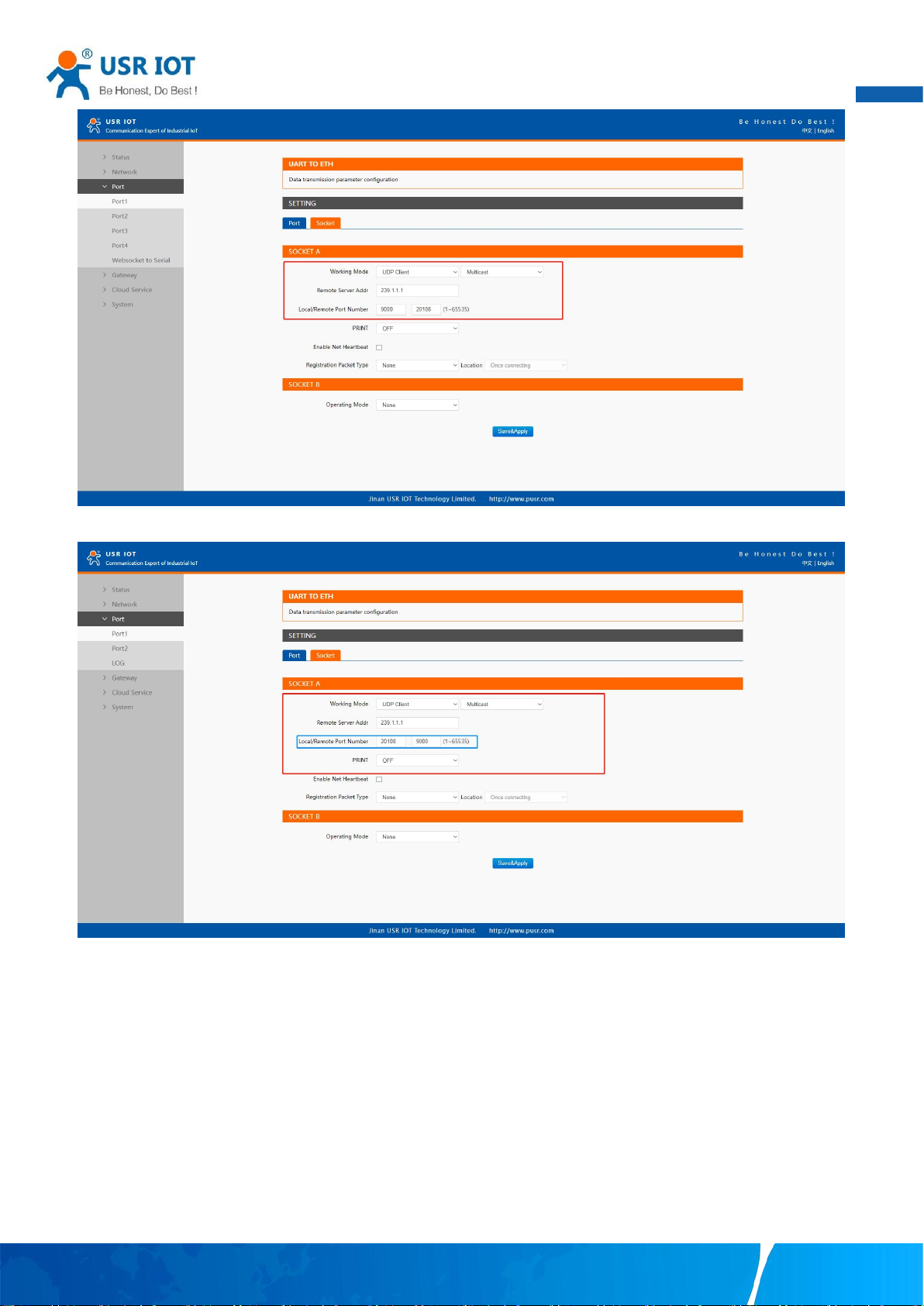
53
Fig. 57 USR-5X0 #1 UDP multicast setting
User Manual
Fig. 58 USR-N5X0 #2 UDP multicast setting
Fig.59 shows an example of test in this mode with two N5X0s.
Your TrustWorthy Industrial IoT Partner www.pusr.com
Page 55
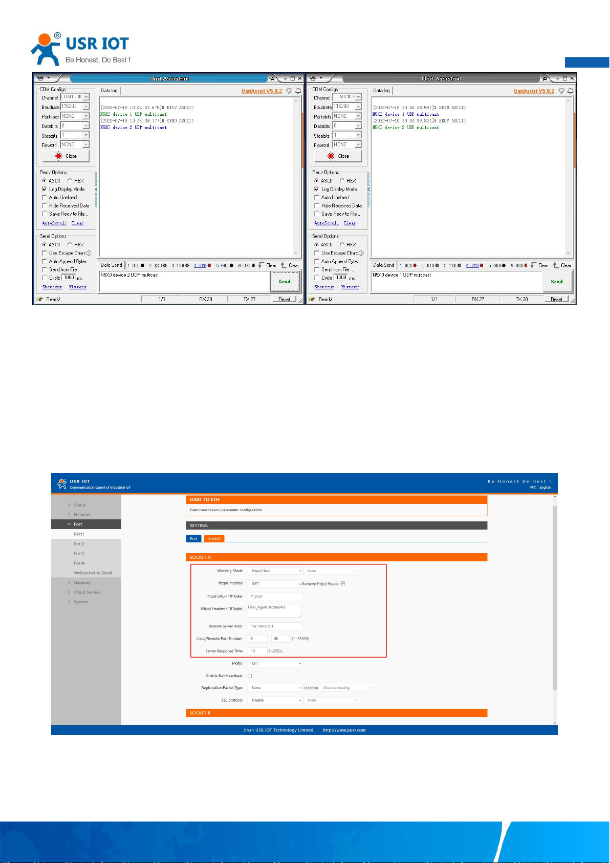
54
4.5. HTTP Client
User Manual
Fig. 59 UDP multicast transmission test
4.5.1. Properties
When the operation mode of this device is Httpd Client, users need to specify the remote httpd server's address, port, method and
other parameters. The device will submit the serially received data to the httpd server in the form of GET or POST. At the same time,
the data sent by the httpd server can be transparently transmitted to the serial port.
Fig.60 shows an example of configuration setting for HTTP Client working mode under the Port1 socket page. You can configure
other serial ports in the same way.
Fig. 60 HTTP client mode
Please follow the following steps to configure connection settings of the work mode for PORT1 port.
1. Click on the “Port1” tab on the menu frame on the left side of Web UI to go to Port1 page as shown in Fig.60.
2. For Serial Settings on the Port configuration page, please go to Section 3.2.3.
Your TrustWorthy Industrial IoT Partner www.pusr.com
Page 56
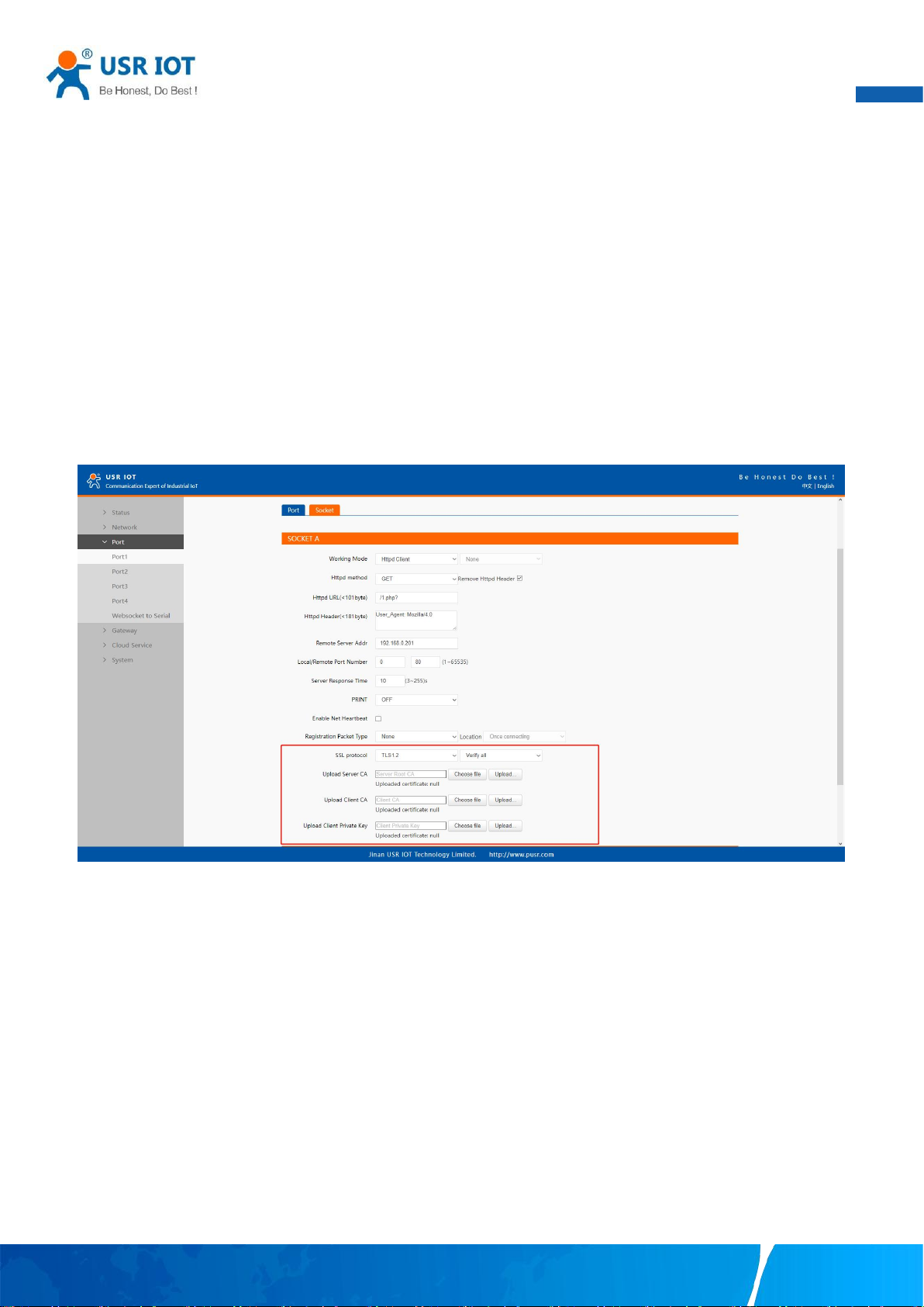
User Manual
55
3. Click on the Socket tab in this page, select Httpd Client in the working mode options.
4. The HTTPD method needs to fill in the correct URL path, and select the GET or POST method as needed.
5. Fill in the HTTPD request header as needed.
6. Fill in the HTTPD address, that is, the address of the HTTP server, which can be an IP address or a domain name (the ability to
connect to foreign countries is required).
7. Fill in the HTTPD port number. The default local port number is 0, N5X0 will assign a random TCP Port.
8. After finishing configuring the working Mode, please scroll down to the bottom of the page and click on "Save & Apply" button to
save all the changes that you have made. All configurations take effect after a system reboot.
4.5.2. HTTPS
If SSL certificate authentication is enabled on the remote server, user need to configure SSL encryption parameters on N5X0. User
can select TLS1.0 or TLS1.2 version protocol. User can select None certificate Authentication, server certificate authentication and
bidirectional certificate authentication.
Fig. 61 SSL/TLS encryption
4.6. Websocket server
When the operation mode of this device is WebSocket server, the user needs to specify the main parameters such as listening port,
forwarding direction. This function is that the serial server acts as a WebSocket server, and transparently transmits the data received
by the serial to the WebSocket client in hexadecimal format. The WebSocket server can also forward data to the serial device at any
time.
1. Click on the “system setting” tab on the menu frame on the left side of Web UI to go to system setting page as shown in Fig.62.
2. Fill in the WebSocket server listening port number,default 6432.
3. Select UART1 in websocket direction.
4. For Serial Settings on the Port configuration page, please go to Section 3.2.3.
Your TrustWorthy Industrial IoT Partner www.pusr.com
Page 57
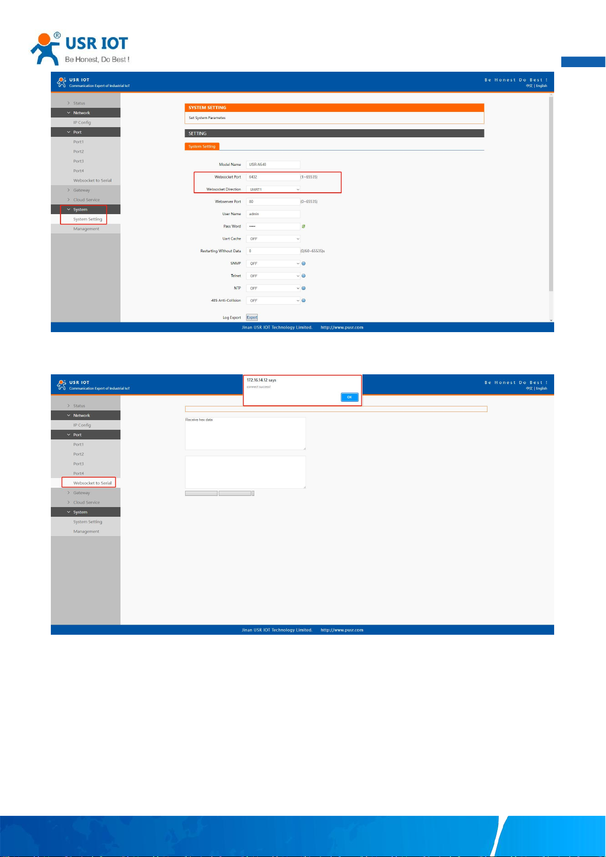
56
Fig. 62 Websocket server setting
User Manual
5. Click on the websocket to serial tab,browser will connect to the websocket server of N5X0 automatically.
Fig. 63 Browser as websocket client to connect N5X0
Fig.64 shows an example of test in this mode.
Your TrustWorthy Industrial IoT Partner www.pusr.com
Page 58
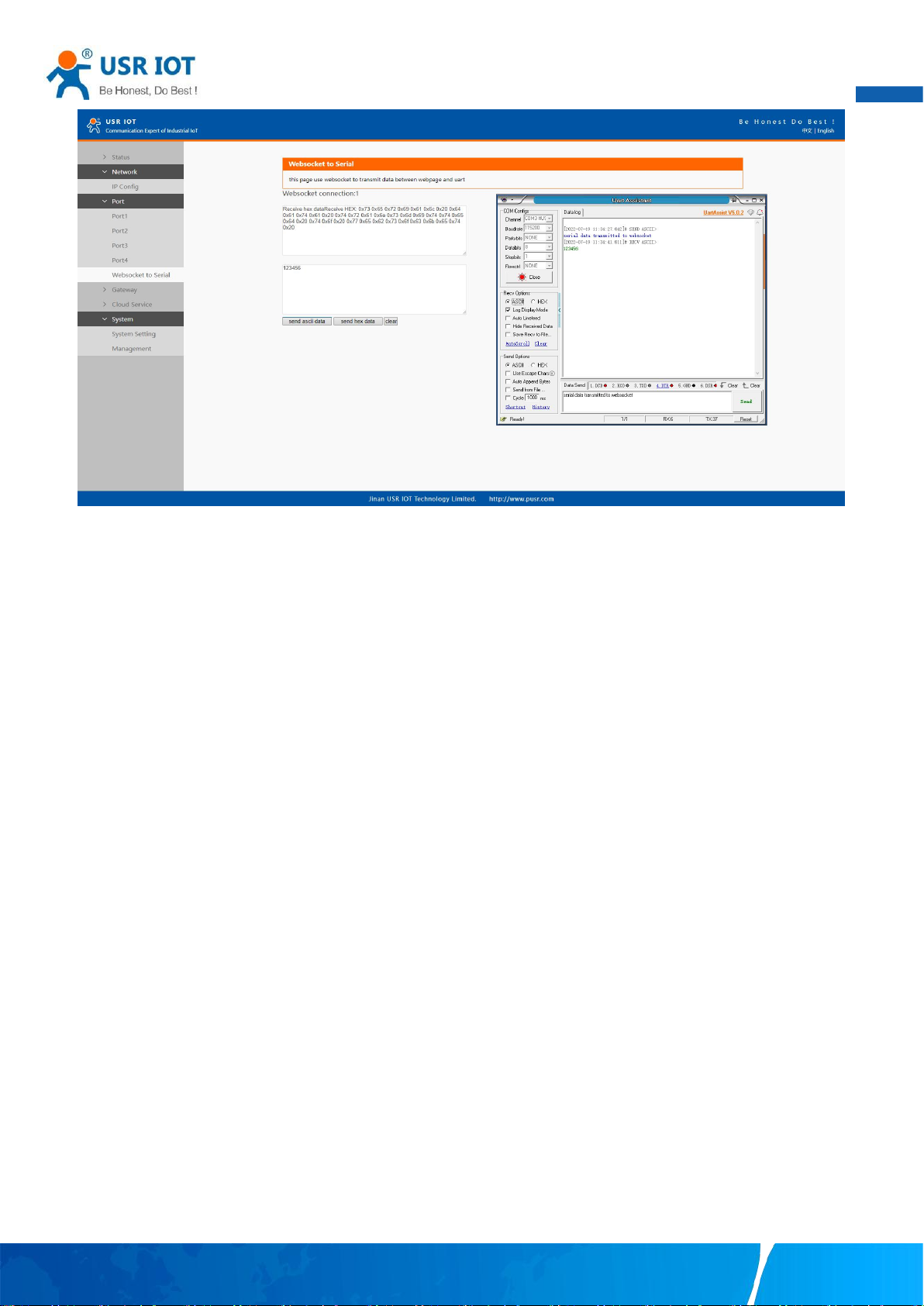
57
Fig. 64 Data transmission test
User Manual
Your TrustWorthy Industrial IoT Partner www.pusr.com
Page 59
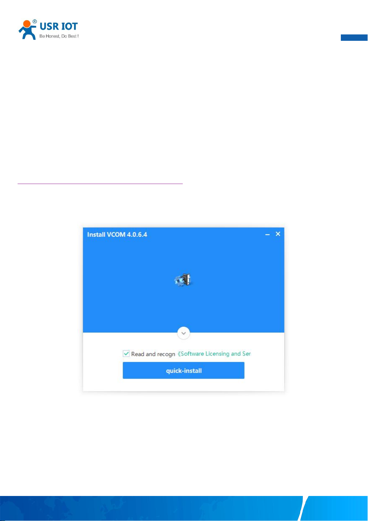
User Manual
58
5. Virtual COM port
Traditional SCADA and data collection systems rely on serial ports (RS-232/422/485) to collect data from various kinds of instruments.
Virtual COM ports on host computer allows remote access of serial devices over TCP/IP network that works like local native COM
ports. Since USR-N5X0 serial device servers enable network operation of instruments equipped with an RS-232/422/485
communication port, your SCADA and data collection system will be able to access all instruments connected to a standard TCP/IP
network, regardless of whether the instruments are used locally or at a remote site.
To enable Virtual COM on host computer, you will require a VCOM software to emulate the COM port. For Windows operating system,
a software utility called VCOM is supported by PUSR to be used for this purpose.
This function is useful with devices such POS terminals, Bar Code Readers, Serial printers, etc. since it allows you to use software that
was written for pure serial communication applications.
Download the software from PUSR’s website:
https://www.pusr.com/support/downloads/VCOM_Setup_exe.html
Execute the VCOM program, click quick-install to install program files in the default directory, or select an alternative location. The
Installing window reports the progress of the installation.
Fig. 65 Install wizard 1
Your TrustWorthy Industrial IoT Partner www.pusr.com
Page 60
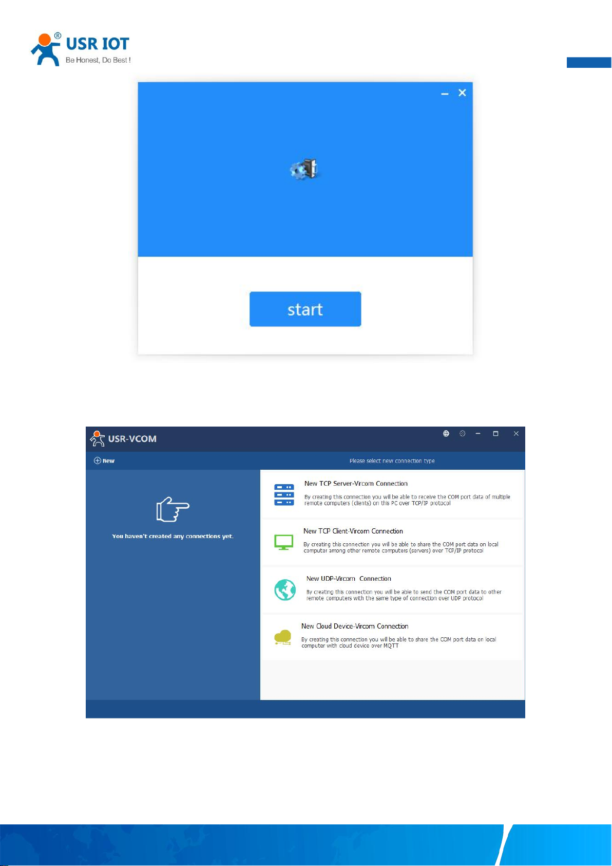
User Manual
59
Fig. 66 Install wizard 2
Once the installation of the package is finished a start screen displays. Click start to conclude the process and launch the VCOM
software.
Fig. 67 VCOM overview
5.1. TCP Server Application with Virtual COM
Virtual COM on host computer allows remote access of serial devices over TCP/IP networks through Serial/IP Virtual COM
ports that work like local native COM ports. Fig.68 is an example of Virtual COM application diagram. There are traditionally only two
Physical COM ports (COM 1 and COM 2) on the personal computer (PC) while there can be several Virtual COM ports such as COM 11,
Your TrustWorthy Industrial IoT Partner www.pusr.com
Page 61
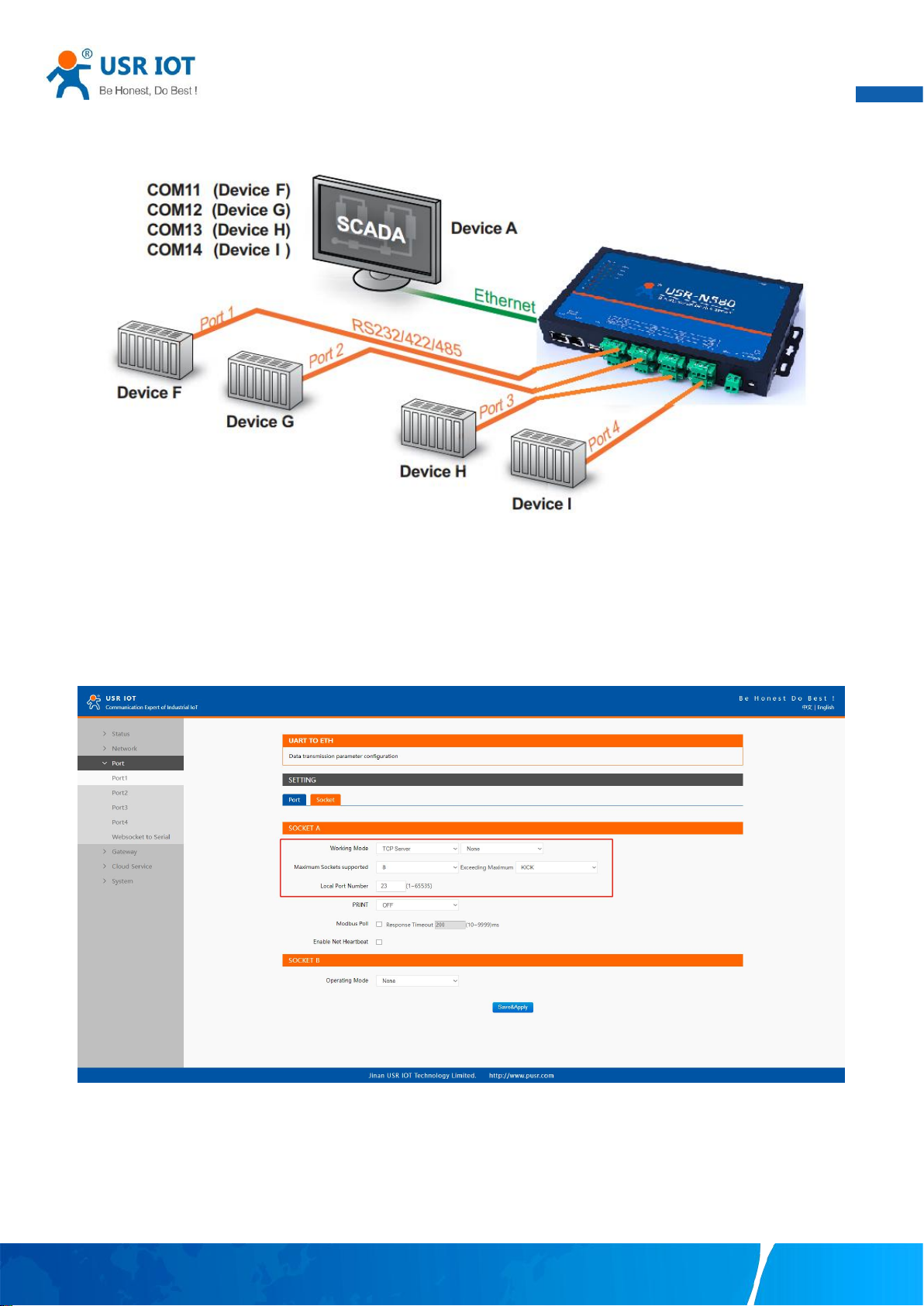
User Manual
60
12, 13, and so on. This section will provide the procedure to enable Virtual COM (VCOM) on Windows based PC. Please follow the
steps described here to configure your Virtual COM application.
Fig. 68 Diagram of Virtual COM Application over TCP/IP Network
1. If the serial device server is running in TCP Server Mode (recommended), the VCOM utility on the host computer should be
configured as the TCP client connecting to the serial device server. The characteristic of this mode is that the IP address of the host
can be changed (usually automatically assigned by the router), and the IP address of the serial server must be fixed.
Fig. 69 TCP server mode in USR-N5X0
Your TrustWorthy Industrial IoT Partner www.pusr.com
Page 62
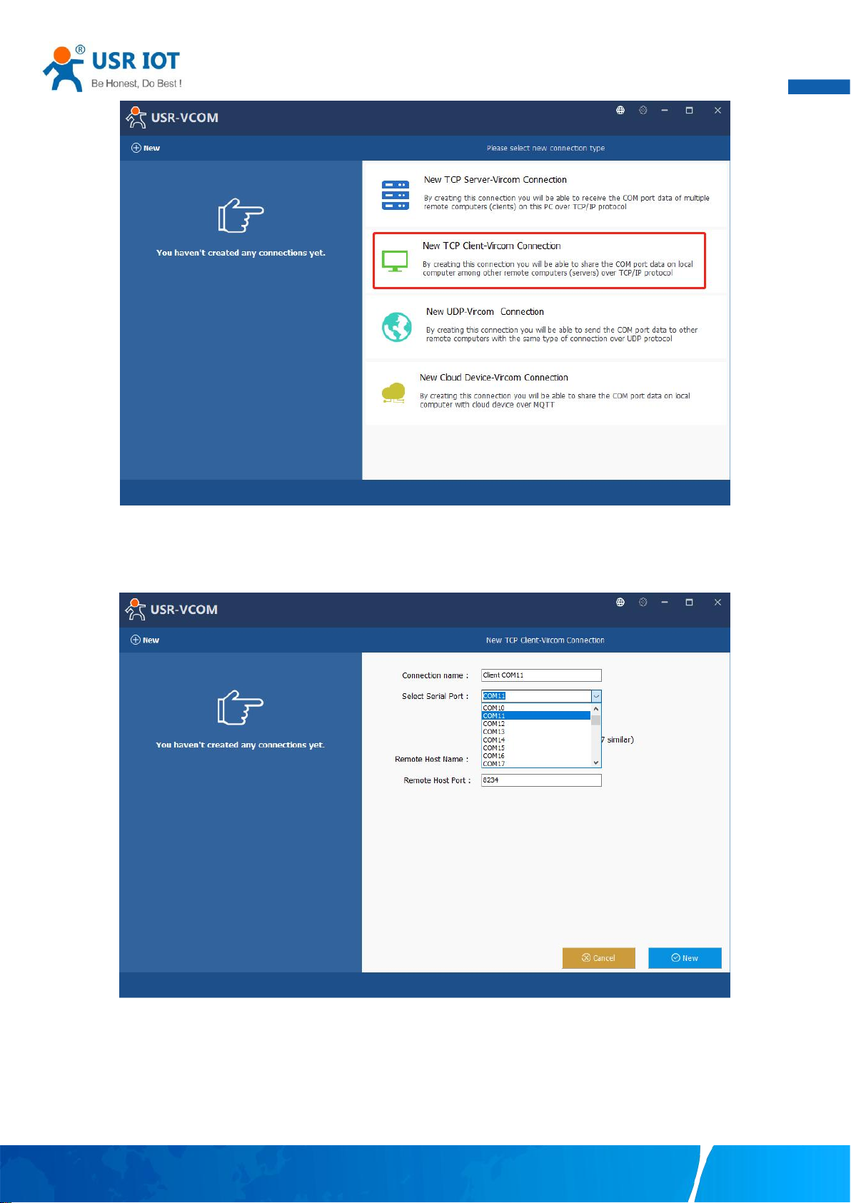
User Manual
61
Fig. 70 New Virtual COM connection
2. Select one COM port as the Virtual COM port before proceeding as shown in Fig.71. Note that if a COM port number is used by
other application or your operating system, you can not select it.
Fig. 71 Select one COM port
3. After selecting the virtual COM ports, please enter the IP Address of the serial device server with the specified Port Number. The
Port Number here is the Local Listening Port for the serial device server which is specified in the Local Port field of Fig.72.
Your TrustWorthy Industrial IoT Partner www.pusr.com
Page 63
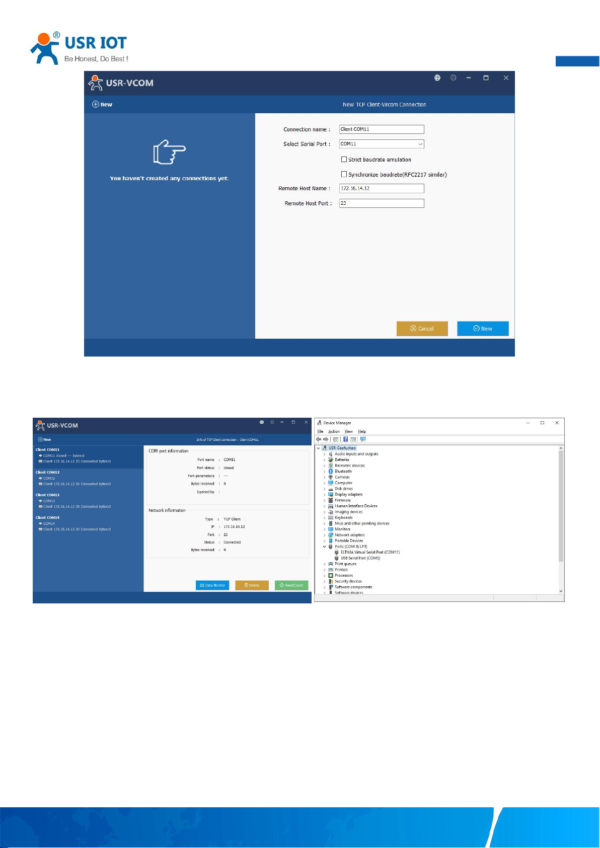
User Manual
62
Fig. 72 Virtual COM port mapping
4. Click new to add the Virtual COM11. Click client COM11 on the left side of VCOM panel to check the status. If status become
connected, the process is completed.
Fig. 73 Virtual COM11 status
5.2. TCP Client Application with Virtual COM
1. If the serial device server is running in TCP Client Mode, the VCOM utility on the host computer should be configured as the TCP
server waiting for a serial device server to connect to the host computer. The feature of this mode is that the IP address of the
computer cannot be changed, but the IP address of the serial device server can be changed (which can be automatically assigned by
the router).
Your TrustWorthy Industrial IoT Partner www.pusr.com
Page 64
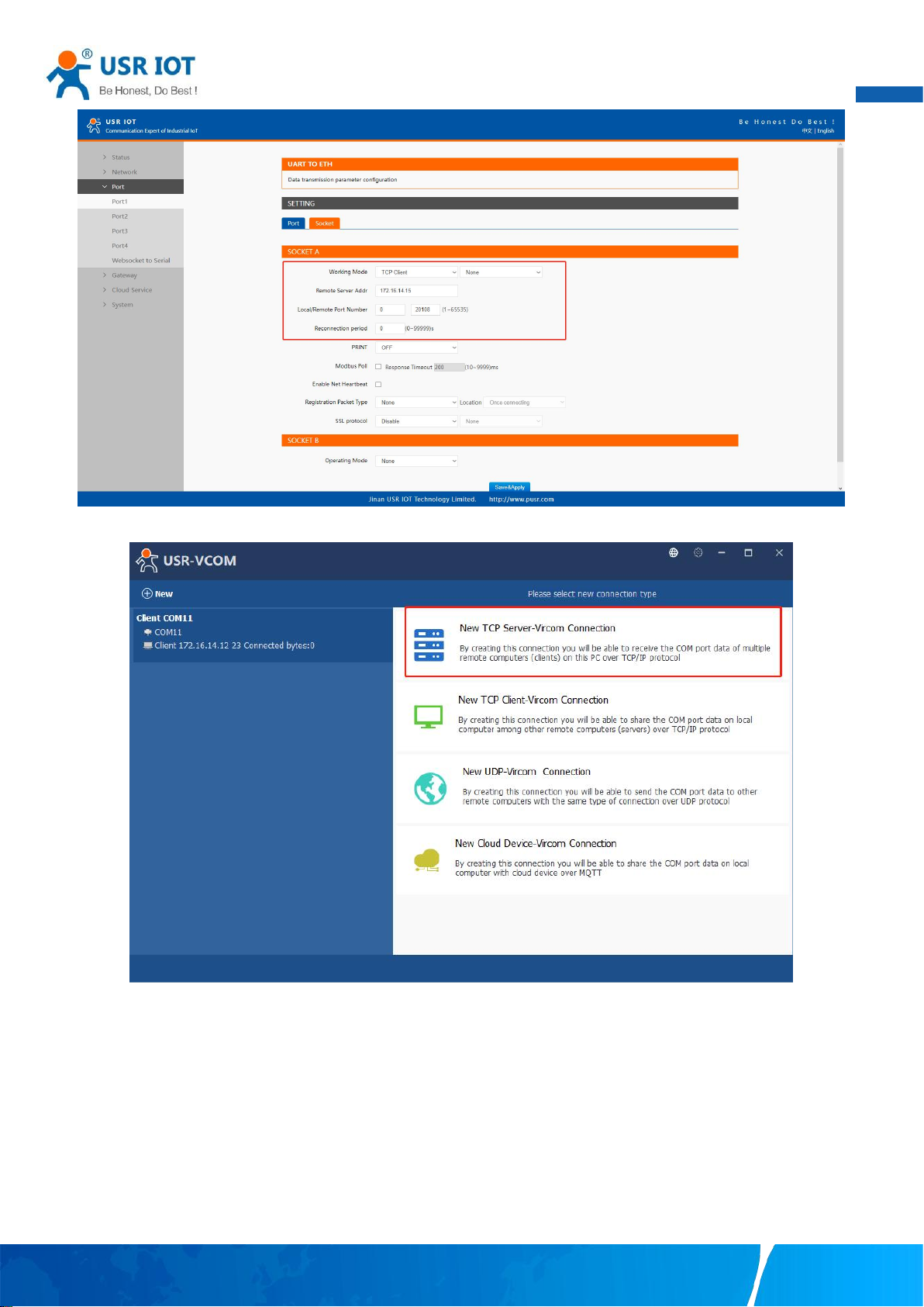
63
Fig. 74 TCP client mode in USR-N5X0
User Manual
Fig. 75 New Virtual COM connection
2. Select one COM port as the Virtual COM port before proceeding as shown in Fig.76. Note that if a COM port number is used by
other application or your operating system, you can not select it.
3. After selecting the virtual COM ports, please enter the specified Port Number. This Port Number is the Destination Port of the
serial device server.
Your TrustWorthy Industrial IoT Partner www.pusr.com
Page 65
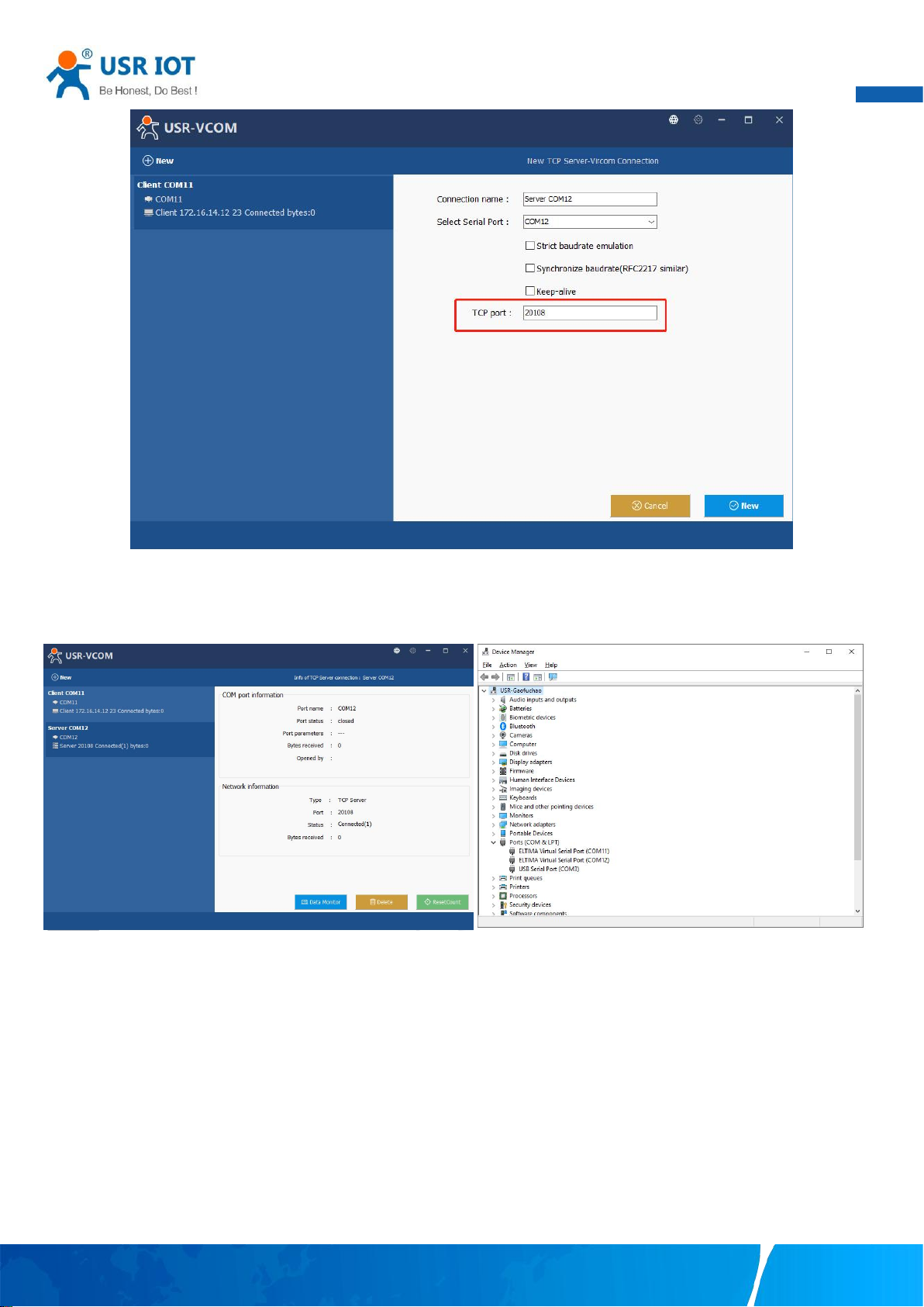
User Manual
64
Fig. 76 Virtual COM port mapping
4. Click new to add the Virtual COM12. Click client COM12 on the left side of VCOM panel to check the status. If status become
connected, the process is completed.
Fig. 77 Virtual COM12 status
5.3. Enable RFC2217 through Virtual COM
Enabling this function allows users to use customized RFC2217 commands on the network to dynamically modify the serial port's
baud rate, data bits, stop bits, and parity bits. This function is only allowed when the working mode is TCP Server and TCP Client. Note
that this protocol is used to change the serial port parameters of USR-N5X0.
Your TrustWorthy Industrial IoT Partner www.pusr.com
Page 66
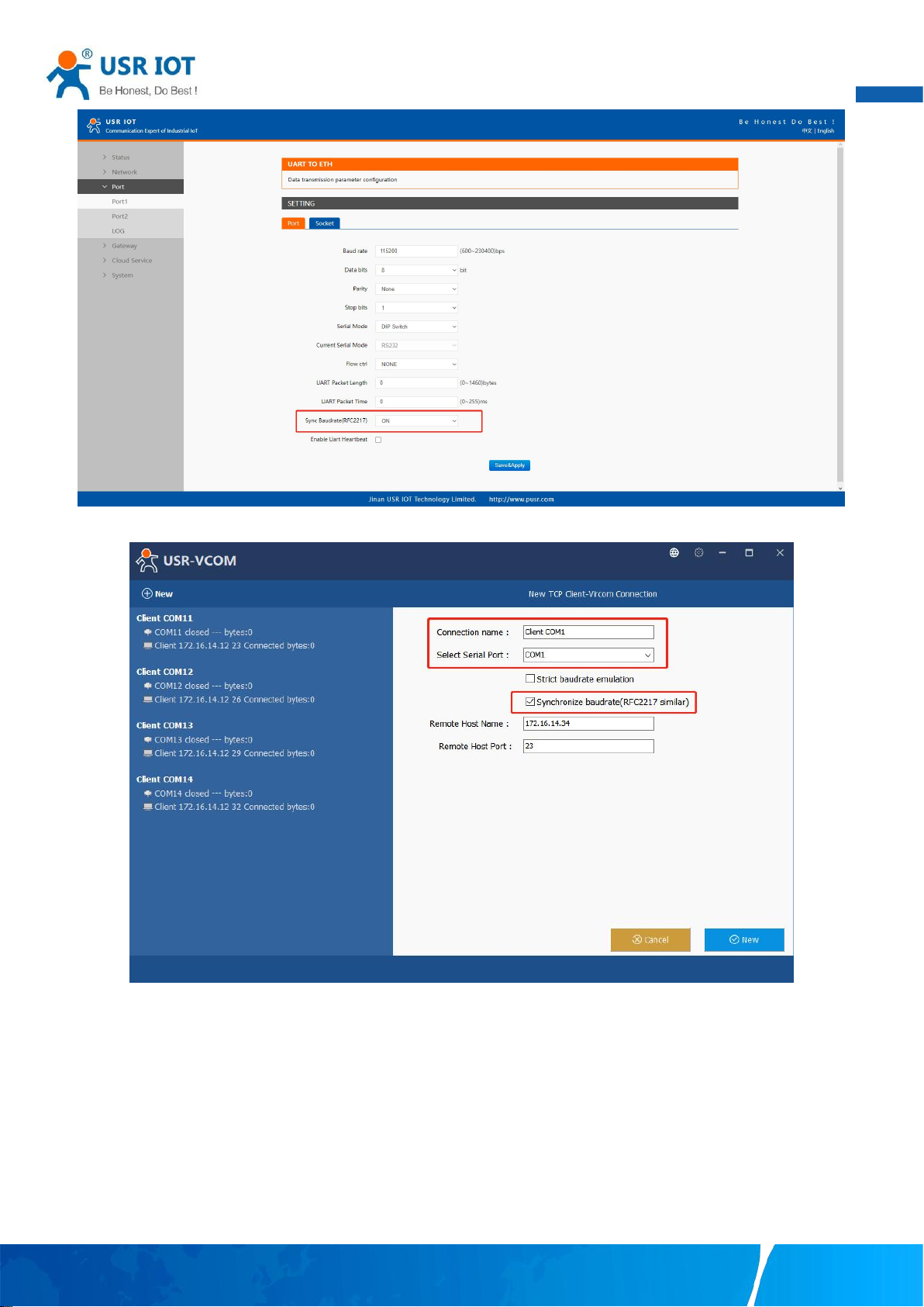
65
Fig. 78 RFC2217 enabled
User Manual
Fig. 79 enable RFC2217 in VCOM
When we change serial parameters in Virtual COM port 1, we can see these parameters have took effect in serial port of USR-N5X0.
Your TrustWorthy Industrial IoT Partner www.pusr.com
Page 67
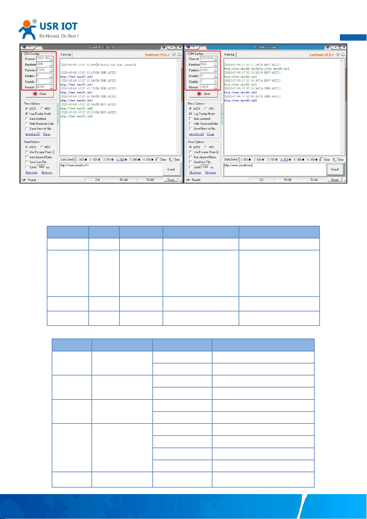
66
Fig. 80 Synchronizing serial port parameters
Name
Header
Baud rate
Serial parameter definition
Sum check
Length(bytes)
331
1
Description
Fixed
Big endian,
e.g.
600(00 02
58)
Data bits/stop bits/parity
bits setting.
AS shown in the table 23
below
Check sum of 4 bytes of
baud rate and serial
parameter definition, retain
the least significant byte
115200,N,8,1
55 AA 55
01 C2 00
03
C6
9600, N,8,1
55 AA 55
00 25 80
03
A8
Bit Position
Function
Value
Description
1:0
Data bits
10
7 Data bits
11
8 Data bits
2
Stop bits
0
1 Stop bits
1
2 Stop bits
3
Parity bit enable
0
disable the parity bit
1
Enable the parity bit
5:4
Parity bit type
00
ODD
01
EVEN
10
Mark
11
Space
7:6
undefinition
00
Please write 0
5.3.1. PUSR customized RFC2217 protocol
User Manual
Table 22 Com Port Control commands
Table 23 Serial parameter definition
Your TrustWorthy Industrial IoT Partner www.pusr.com
Page 68
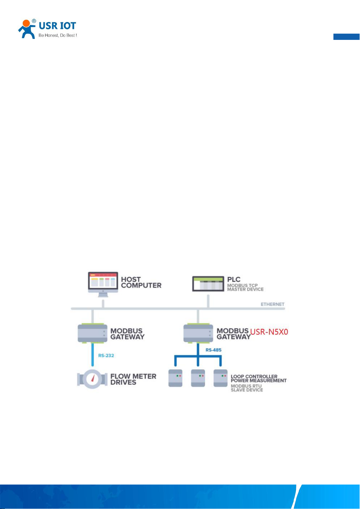
User Manual
67
6. Modbus TCP/RTU gateway
Modbus is one of the most popular automation protocols in the world, supporting traditional RS-232/422/485 devices and recently
developed Ethernet devices. Many industrial devices, such as PLCs, DCSs, HMIs, instruments, and meters, use Modbus as their
communication standard. In industrial applications, the most common protocol conversion is Modbus RTU to Modbus TCP conversion,
and it is usually required when legacy devices such as meters, mostly using Modbus RTU, need to be integrated with SCADA systems,
mostly using Modbus TCP.
Most modern PLCs and host computers support Modbus TCP over Ethernet. In order to access discrete Modbus RTU devices for data
collection and control, they can rely on the N5X0 Modbus gateway.
When connecting up Modbus devices via an RS485 network they should be daisy chained together, and a dual twisted pair cable are
recommended.The connections should be kept the same throughout the network: positive to positive, and negative to negative.
These may sometimes be labelled up as A and B. When wiring Modbus serial devices there is a limit of 32 per network,the master
device takes up an address on the network.The maximum length of the serial network cannot exceed 1200m regardless of boosters
and repeaters.
6.1. Ethernet masters with serial slaves
When the host computer or PLC is Modbus TCP Master, the Modbus TCP function must be enabled, the remote device must work in
Modbus RTU Slave mode. The N5X0(TCP Server mode) supports Modbus TCP with up to 16 simultaneous connections. The serial
interface supports both RS-232 and RS-422/485, selectable through software. Each serial port can be connected to one RS-232 or
RS-422 serial device, or to 32 RS-485 serial devices. When connected with more than one RS485 devices,please refer to section 7.5
for bus collision detection.
Fig. 81 Ethernet masters with multiple serial slaves
The device supports multiple hosts to query data from the slave in q&A mode. Please select modbus polling function as shown in
Fig.82. When USR-N5X0 Series serial device server does not receive a response from the serial port after a response timeout, the
device replies with an acknowledgement and then processes the next host request.
When you need to use long frame data frequently or have high data transmission requirements, please adjust the baud rate and
lengthen the sending interval appropriately to prevent the slow serial port from causing messy codes or packet loss.
Your TrustWorthy Industrial IoT Partner www.pusr.com
Page 69
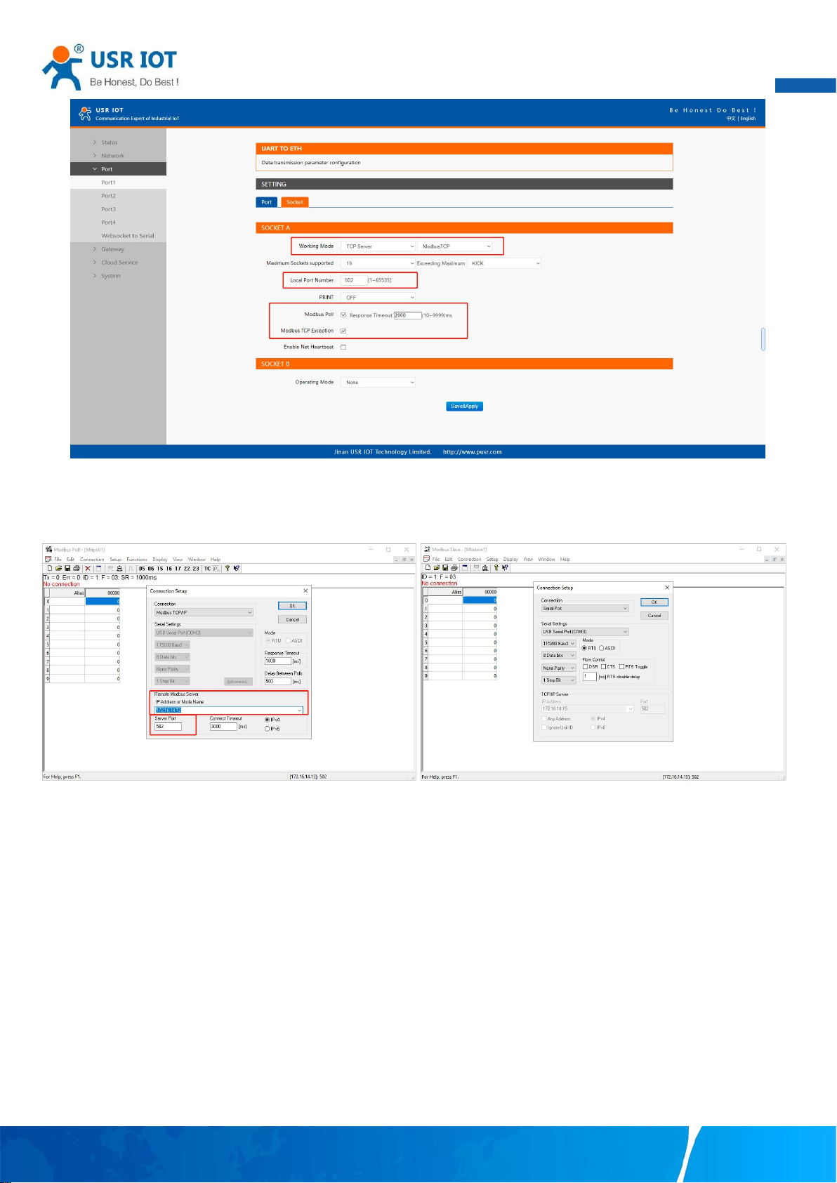
68
Fig. 82 Modbus TCP master settings
User Manual
Open the Modbus Poll and Modbus Slave software, go to "Connect" -> "Connect", and the connection parameters are configured as
follows, in this case, IP address of USR-N5X0 is 172.16.14.12.
Fig. 83 Modbus emulator settings(Ethernet master and serial slave)
6.2. Serial master with Ethernet slave
Many HMI (Human Machine Interface) systems use a serial interface to connect to a discrete DCS (Data Control System). However,
many DCSs are now Ethernet-based and operate as a Modbus TCP server device. The N5X0 Modbus gateway can link a serial-based
HMI to distributed DCSs over an Ethernet network.
When the host computer or HMI is Modbus RTU Master, if the remote device work in Modbus TCP Slave mode, the ModbusTCP
function must be enabled. The N5X0(TCP Client mode) supports only one Modbus TCP slave.
Your TrustWorthy Industrial IoT Partner www.pusr.com
Page 70
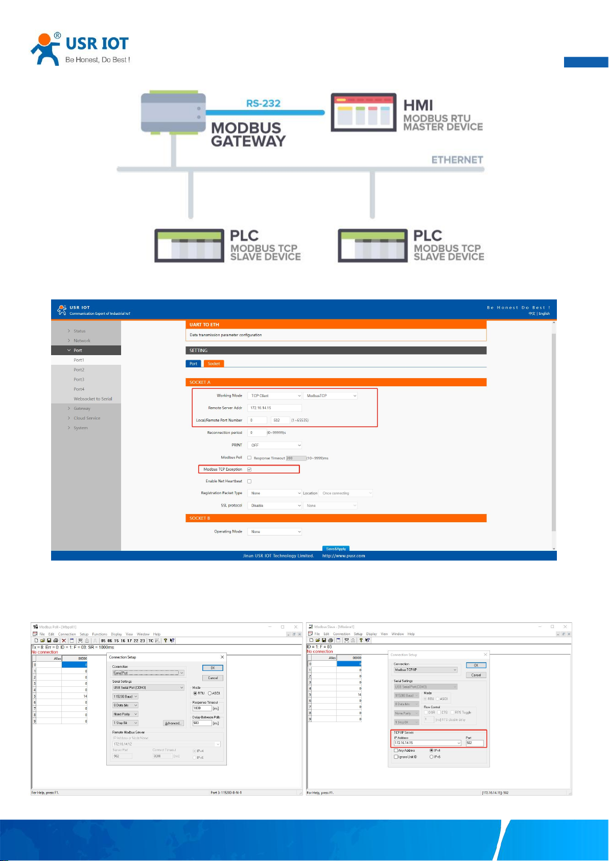
69
Fig. 84 Serial master with one Ethernet slave
User Manual
Fig. 85 Modbus TCP slave settings
Open the Modbus Poll and Modbus Slave software, go to "Connect" -> "Connect", and the connection parameters are configured as
follows, in this case, IP address of USR-N5X0 is 172.16.14.12, host IP address is 172.16.14.15.
Fig. 86 Modbus emulator settings(serial master and Ethernet slave)
Your TrustWorthy Industrial IoT Partner www.pusr.com
Page 71
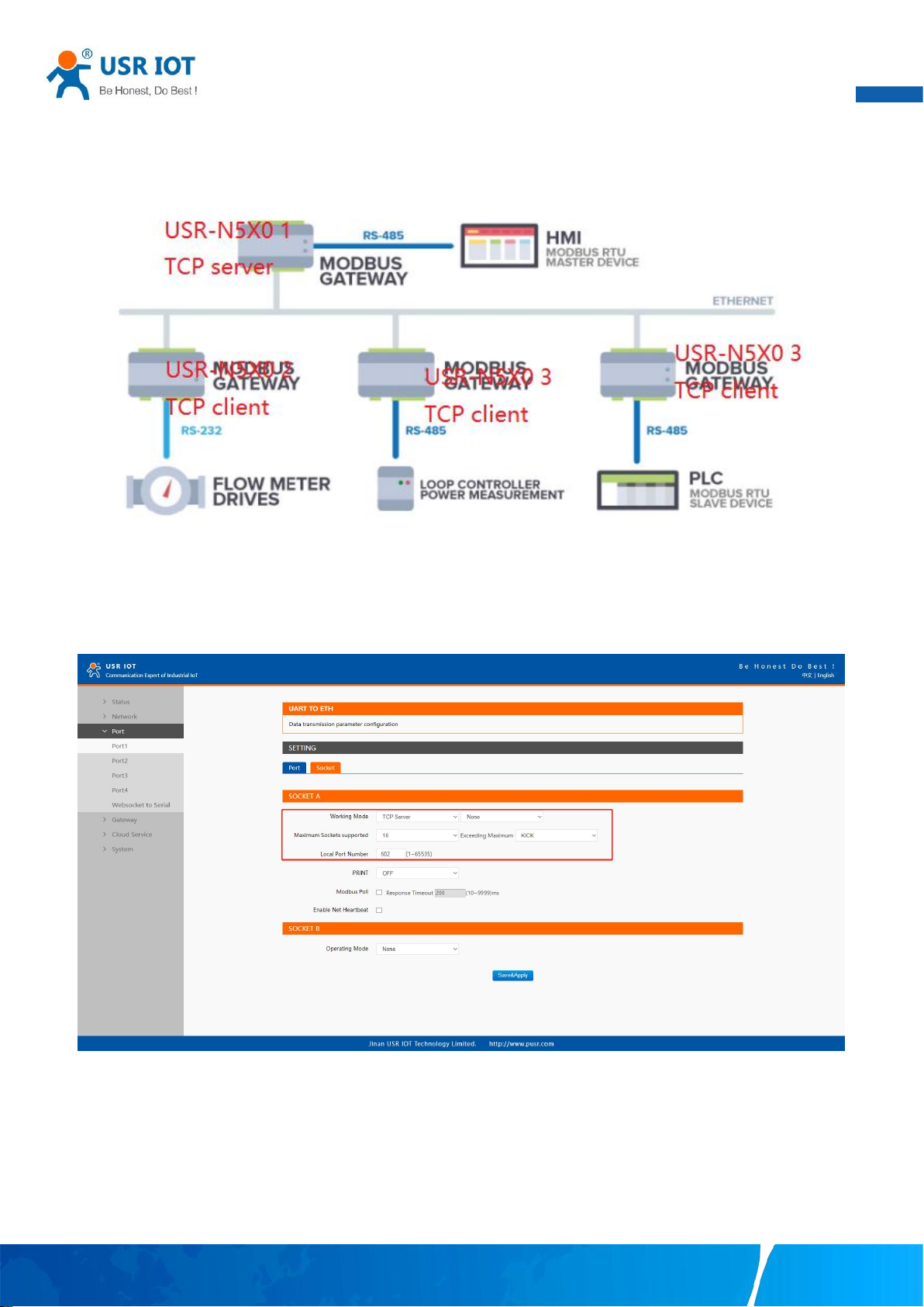
User Manual
70
6.3. Serial master with serial slaves
When the HMI is Modbus RTU Master, all N5x0 must enable or disable ModbusTCP function at the same time, the remote device
must work in Modbus RTU Slave mode. The N5X0 supports up to 16 simultaneous TCP connections.
Fig. 87 Serial master with multiple serial slaves
If there are more than one serial masters in RS485 network, users should select modbus poll function and configure response timeout
in Fig.88. please refer to section 7.5 for bus collision detection.
Fig. 88 Modbus RTU master settings(USR-N5X0 1)
Your TrustWorthy Industrial IoT Partner www.pusr.com
Page 72
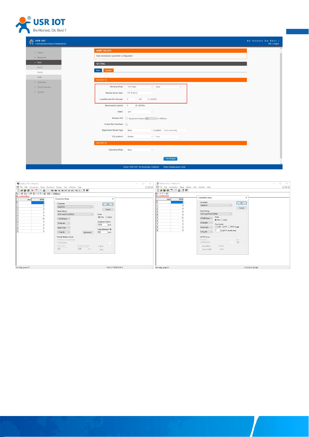
71
Fig. 89 Modbus RTU slave settings(USR-N5X0 2,3,4...)
User Manual
Fig. 90 Modbus emulator settings(serial master and serial slave)
6.4. Serial master via virtual COM with serial slaves
When the host computer is Modbus RTU master, if we use VCOM, the Modbus TCP function must be disabled, the remote device
must work in Modbus RTU Slave mode.
Your TrustWorthy Industrial IoT Partner www.pusr.com
Page 73
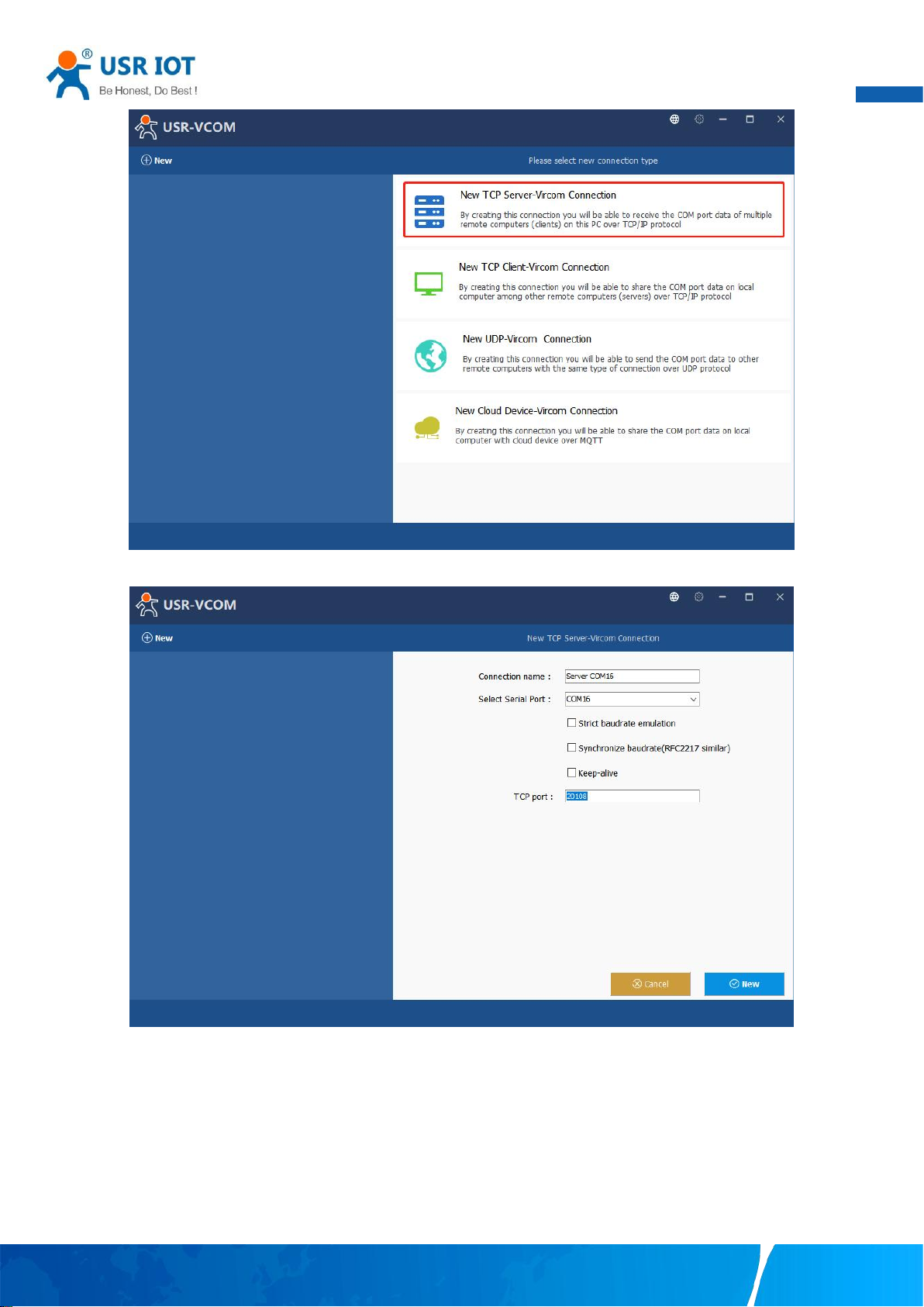
User Manual
72
Fig. 91 New virtual COM port mapping
Fig. 92 Mapping a virtual COM port
Your TrustWorthy Industrial IoT Partner www.pusr.com
Page 74
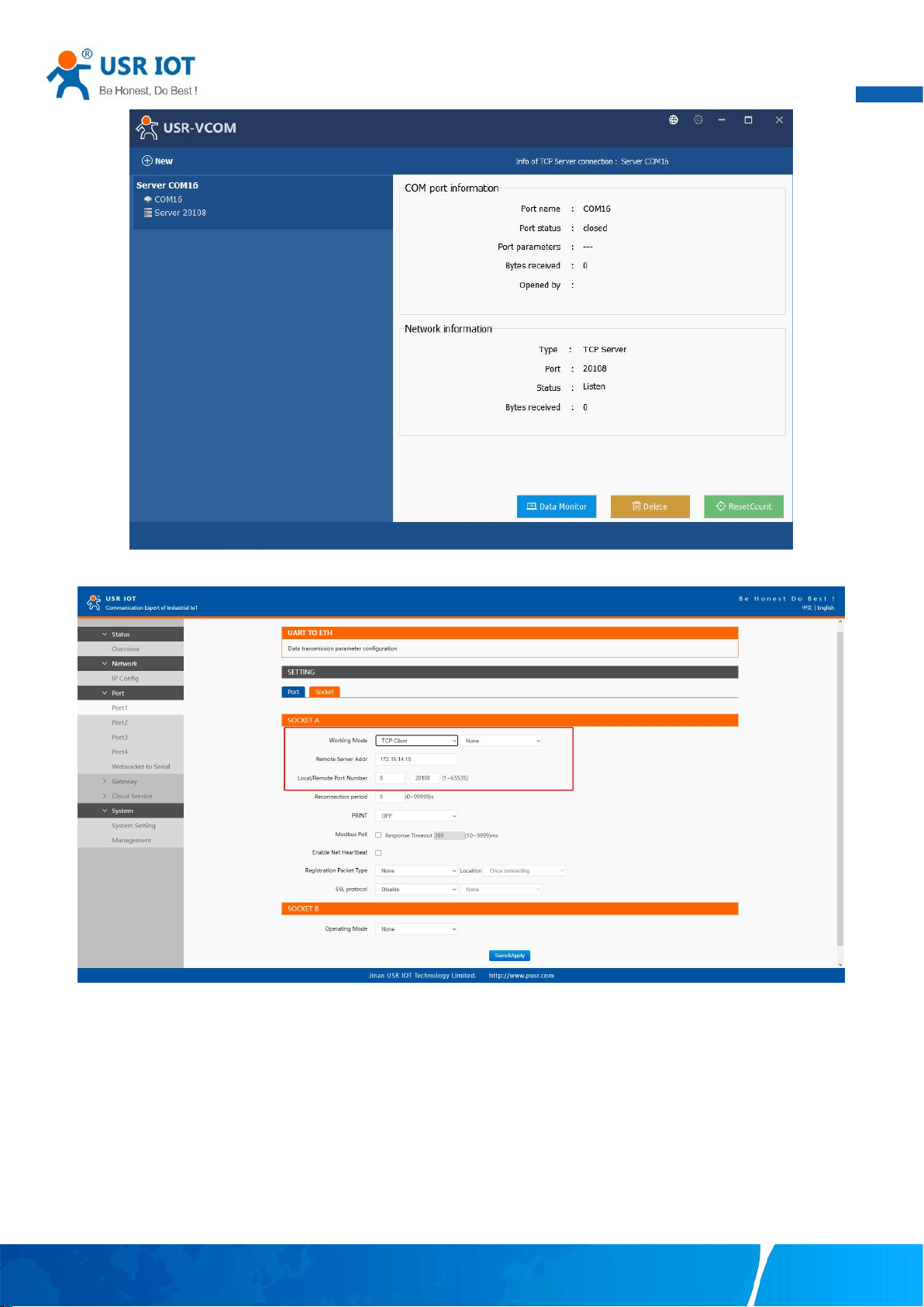
User Manual
73
Fig. 93 Virtual COM port mapping details
Fig. 94 Serial device settings
Your TrustWorthy Industrial IoT Partner www.pusr.com
Page 75
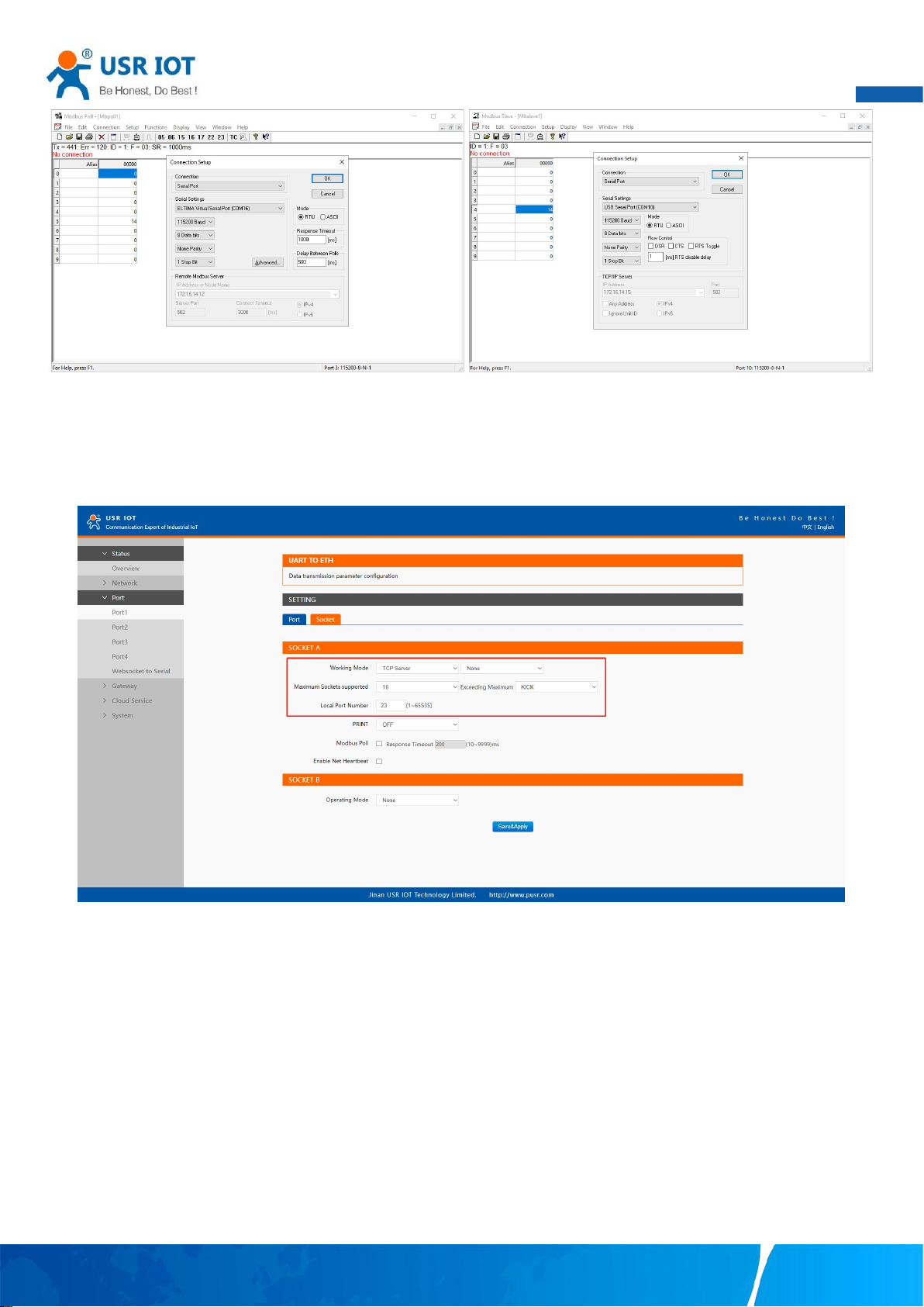
User Manual
74
Fig. 95 Modbus emulator settings(serial master and serial slave)
6.5. Modbus poll with serial heartbeat packet
When the N5X0 is Modbus RTU Master, the serial device work in Modbus RTU Slave mode, the ModbusTCP function must be
disabled. N5X0 works in TCP server mode, it supports up to 16 TCP connections.
Fig. 96 Modbus RTU master Settings
Your TrustWorthy Industrial IoT Partner www.pusr.com
Page 76
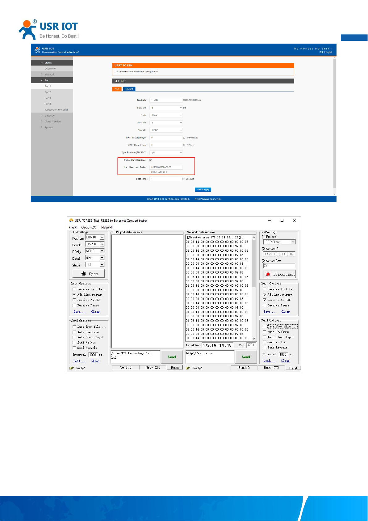
75
Fig. 97 Serial heartbeat packet as modbus command
User Manual
Fig. 98 Modbus response transparently transmission
Your TrustWorthy Industrial IoT Partner www.pusr.com
Page 77
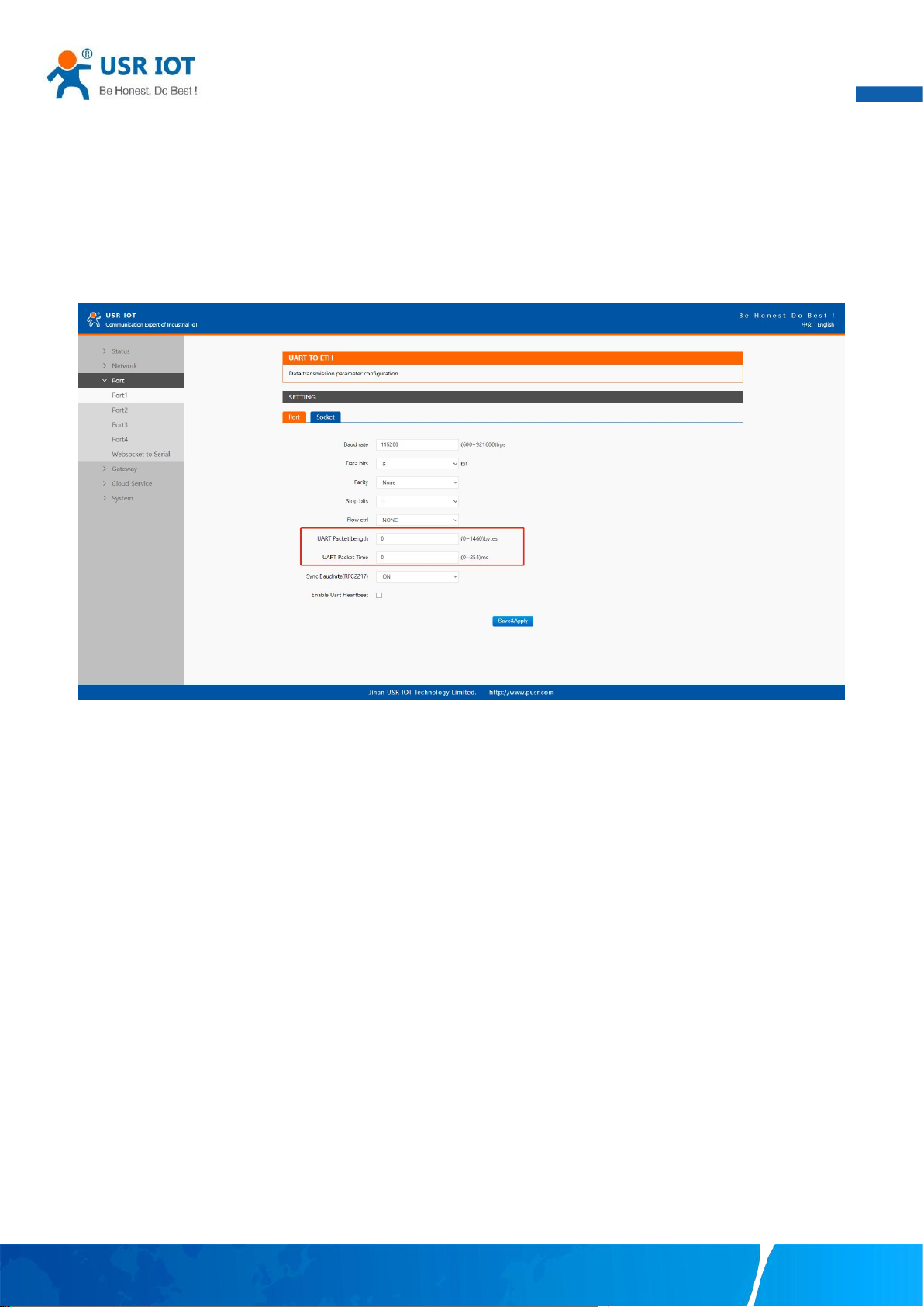
User Manual
76
7. Advanced features
7.1. Packing mechanism
Serial to Network Packet Delimiter: Packet delimiter is a way of packing data in the serial communication. It is designed to keep
packets intact. USR-N5X0 provides two types of delimiter: Time Delimiter, Maximum Bytes Delimiter. Note that the following
delimiters (time, length) when they are selected are programmed in the OR logic. Meaning that if any of the two conditions were met,
the device would transmit the serial data in its buffer over the network.
Fig. 99 Data packing mechanism
Packet time: USR-N5X0 will transmit the serial data in its buffer when the specified time interval has reached and no more serial data
comes in. The default value is calculated automatically based on the baud rate. If the automatic value results in chopped data, the
timeout could be increased manually by specifying a larger value in the text box above. Note that the maximum interval is 255
milliseconds. This option is disabled by default.
The optimal “ Interval timeout ” depends on the application, but it must be at least larger than one-character interval within the
specified baud rate. For example, assuming that the serial port is set to 1200 bps, 8 data bits, 1 stop bit, and no parity. In this case, the
total number of bits needed to send a character is 10 bits (included 1 start bit), and the time required to transfer one character is (10
(bits)/1200 (bits/s))*1000 (ms/s) = 8.3 ms. Therefore, you should set the “Interval timeout” to be larger than 8.3 ms. Rounding 8.3 ms
to the next integer would give you 9 ms. Which can be set as your interval timeout.
Packet length: USR-N5X0 will transmit the serial data in its buffer when the specified length in the unit of bytes has reached. If you
would like USR-N5X0 to queue the data until it reaches a specific length,the data length can be configured for 1 to 1460 bytes. If the
data length (in bytes) matches the configured value, the data will be forced out. Set to 0 if you do not need to limit the length.
7.2. Heartbeat packet
Network heartbeat packet: The serial device server sends a heartbeat packet regularly to notify the server that it is active and
maintains a normal network connection with the server. This function is only allowed when the working mode is UDP and TCP Client.
Serial heartbeat packet: The serial device server notifies the serial device it is active via packet, and this packet can also be used to
actively capture sensor data.
Your TrustWorthy Industrial IoT Partner www.pusr.com
Page 78
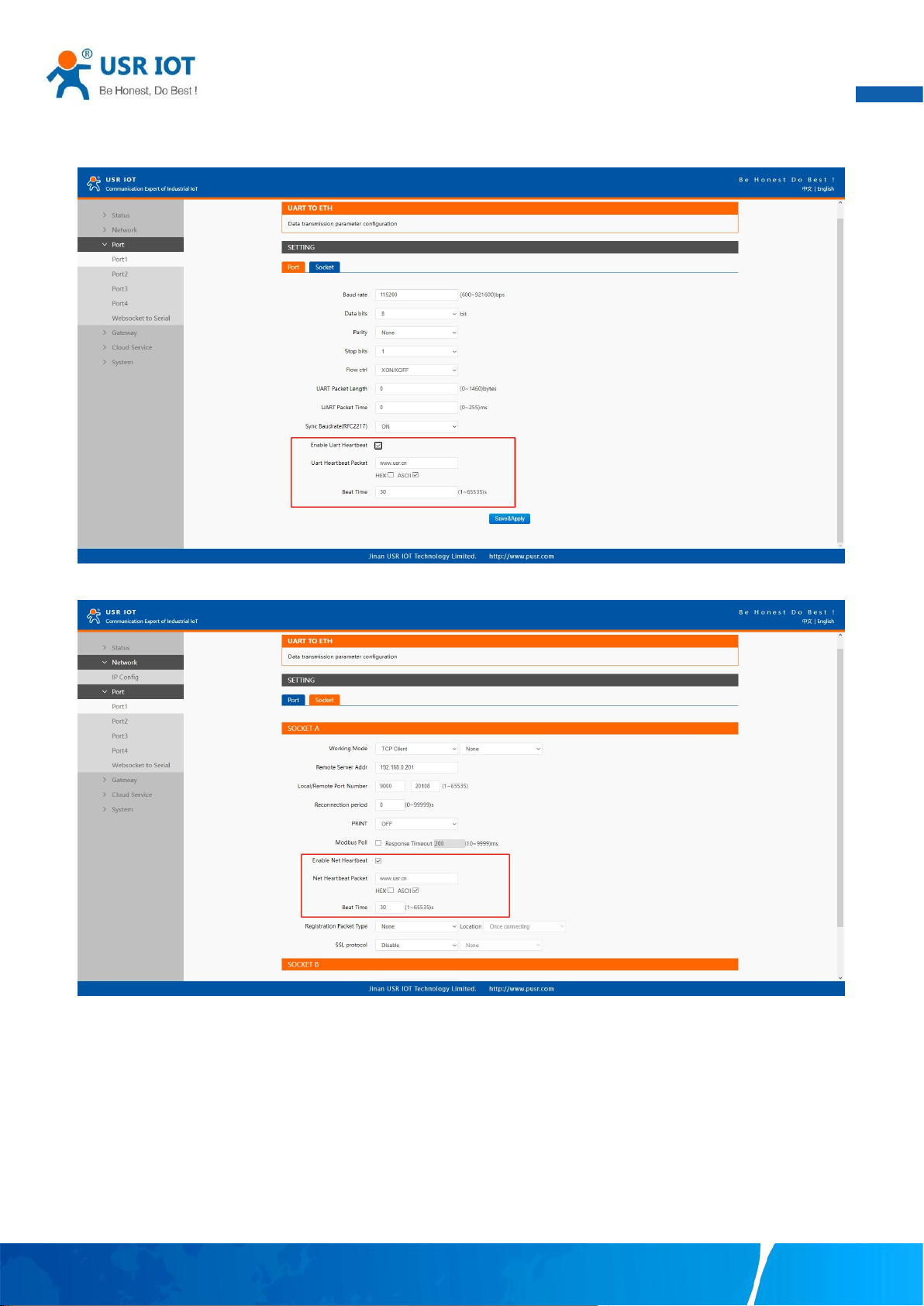
User Manual
77
Heartbeat packet only works in no data traffic in the setting direction. There are no data coming from serial port or internet in
heartbeat interval.
Fig. 100 Serial heartbeat packets
Fig. 101 Network heartbeat packets
7.3. Registration packet
This function is only allowed when the working mode is UDP and TCP Client. The content of the registration packet can be up to 40
bytes long. Users can choose to display this content in hexadecimal format or ASCII format.
Once connected: The registration packet is only sent once when the network connection is established;
Prefix of DATA: The registration packet is filled in front of the serial port data every time the serial port sends data to the network;
Your TrustWorthy Industrial IoT Partner www.pusr.com
Page 79
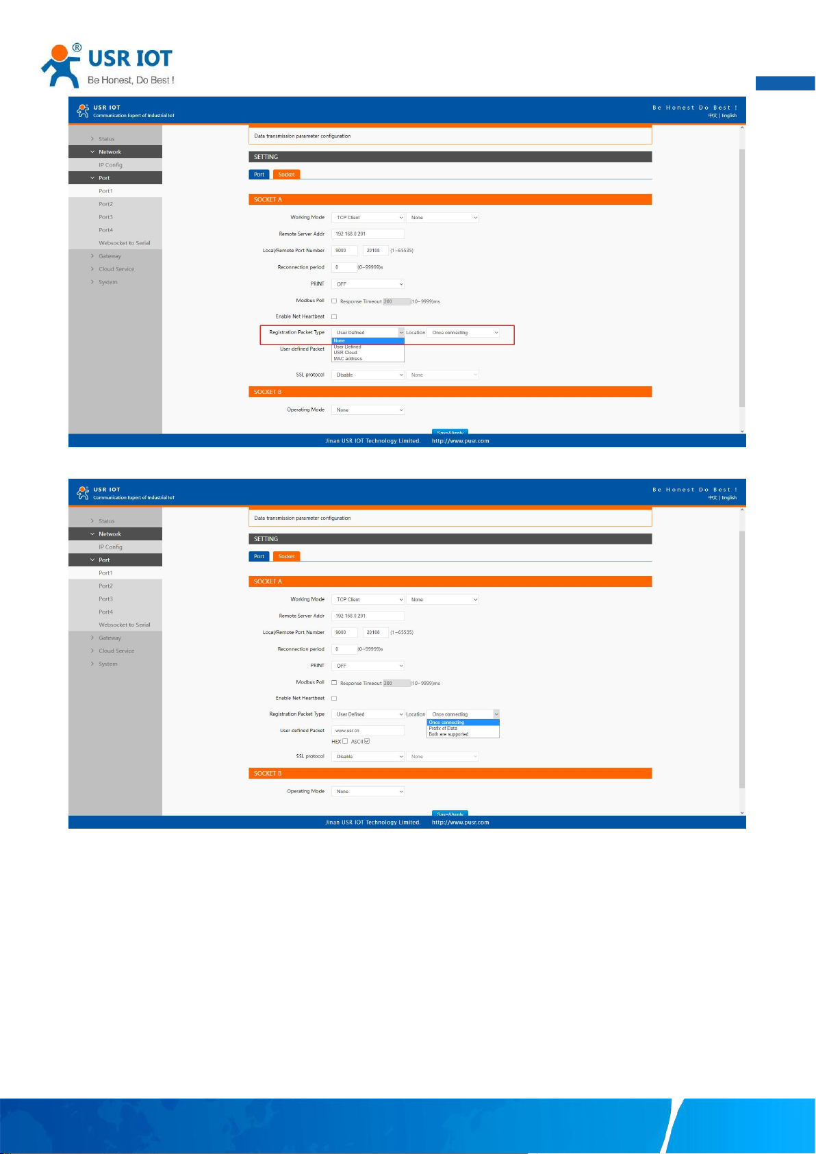
78
Fig. 102 Registration packet type
User Manual
Fig. 103 Registration packet method
7.4. Socket B
Socket B supports TCP Client and UDP Client. Socket B and Socket A share the registration packet and heartbeat packet. When
Socket B initiates a connection, it uses a random local port number to connect to the target server.
Your TrustWorthy Industrial IoT Partner www.pusr.com
Page 80
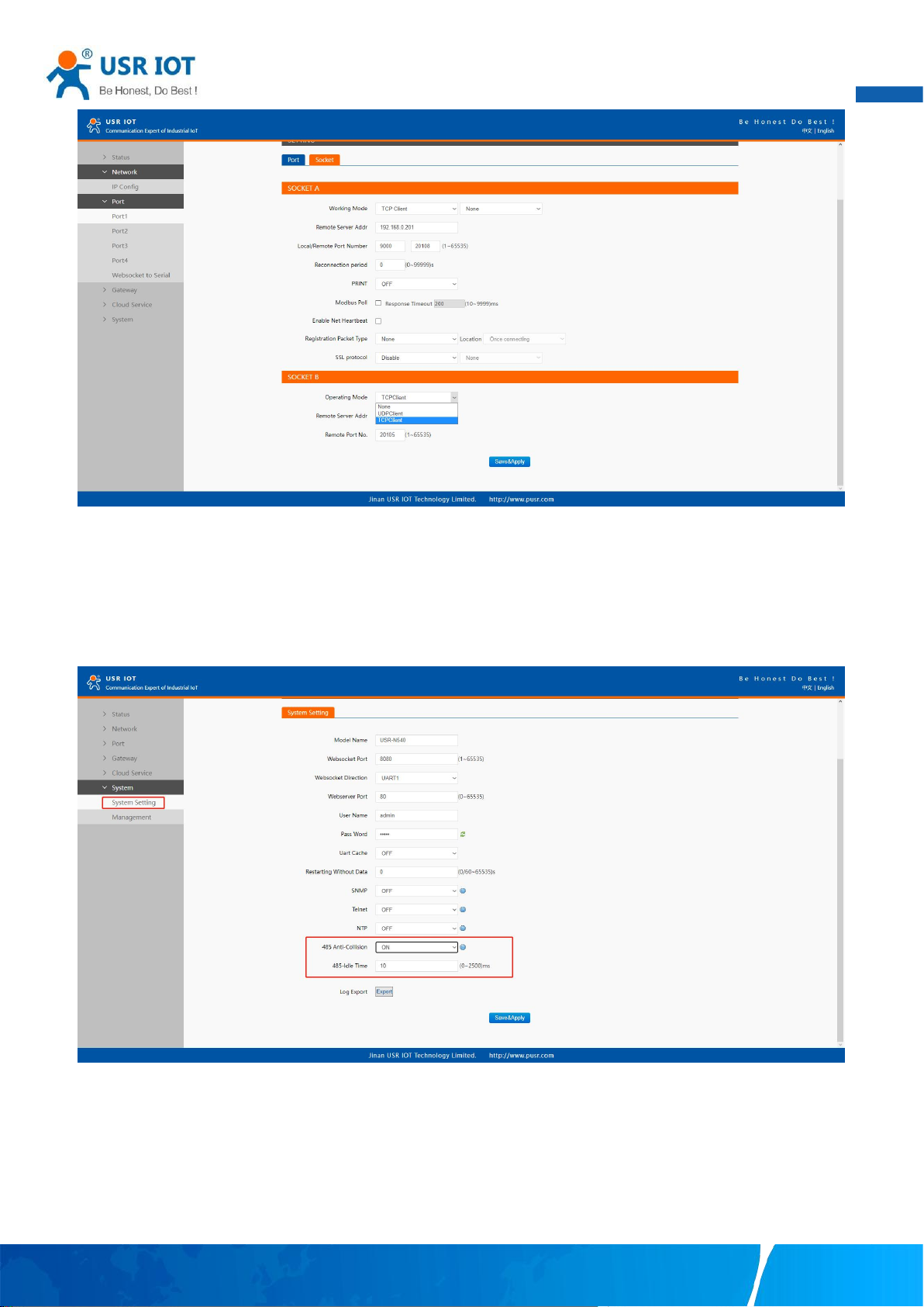
79
Fig. 104 Socket B operating mode
User Manual
7.5. Rs485 bus detection
If RS485 bus is in the receiving state, N5X0 can not output data to serial port to achieve the 485 bus anti-conflict function.
Idle time: the interval time when N5X0 is allowed to send data to RS485 bus after the receiver is idle. The value ranges from 0 to
65535 (ms). Default value: 10. This parameter is mandatory.
Fig. 105 RS485 bus detection
7.6. Serial Printer setting
Serial device servers transform any serial device into an Ethernet-capable device that can be used in a network. These servers allow
serial devices such as a printer, control mechanisms or control systems to be used in a network without relying on the serial port of a
computer for connectivity. This way, any serial device can be connected to the network and the internet and accessed from anywhere.
Sharing a printer among coworkers in the same physical office can be implemented with a simple serial server that does not need to
Your TrustWorthy Industrial IoT Partner www.pusr.com
Page 81
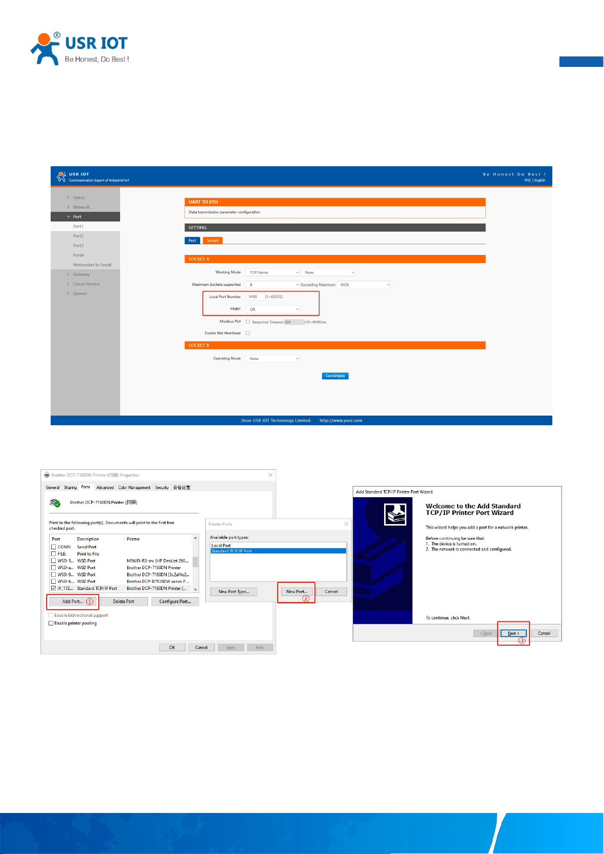
User Manual
80
offer security or authorization capabilities.
The serial device server, N5X0, features a Serial Printer option which functions in similar fashion to the Serial Printer option in the
(COM) Ports dialog box. This option allows the associated TCP port to be identified as a serial printer connection. The connection
does not consume a user license, is restricted to output only, and filters out the end-of-document marker correctly. In this case, IP
address of USR-N5X0 is 172.16.14.12.
Fig. 106 Serial printer option
Fig. 107 Serial printer setting wizard 1
Your TrustWorthy Industrial IoT Partner www.pusr.com
Page 82
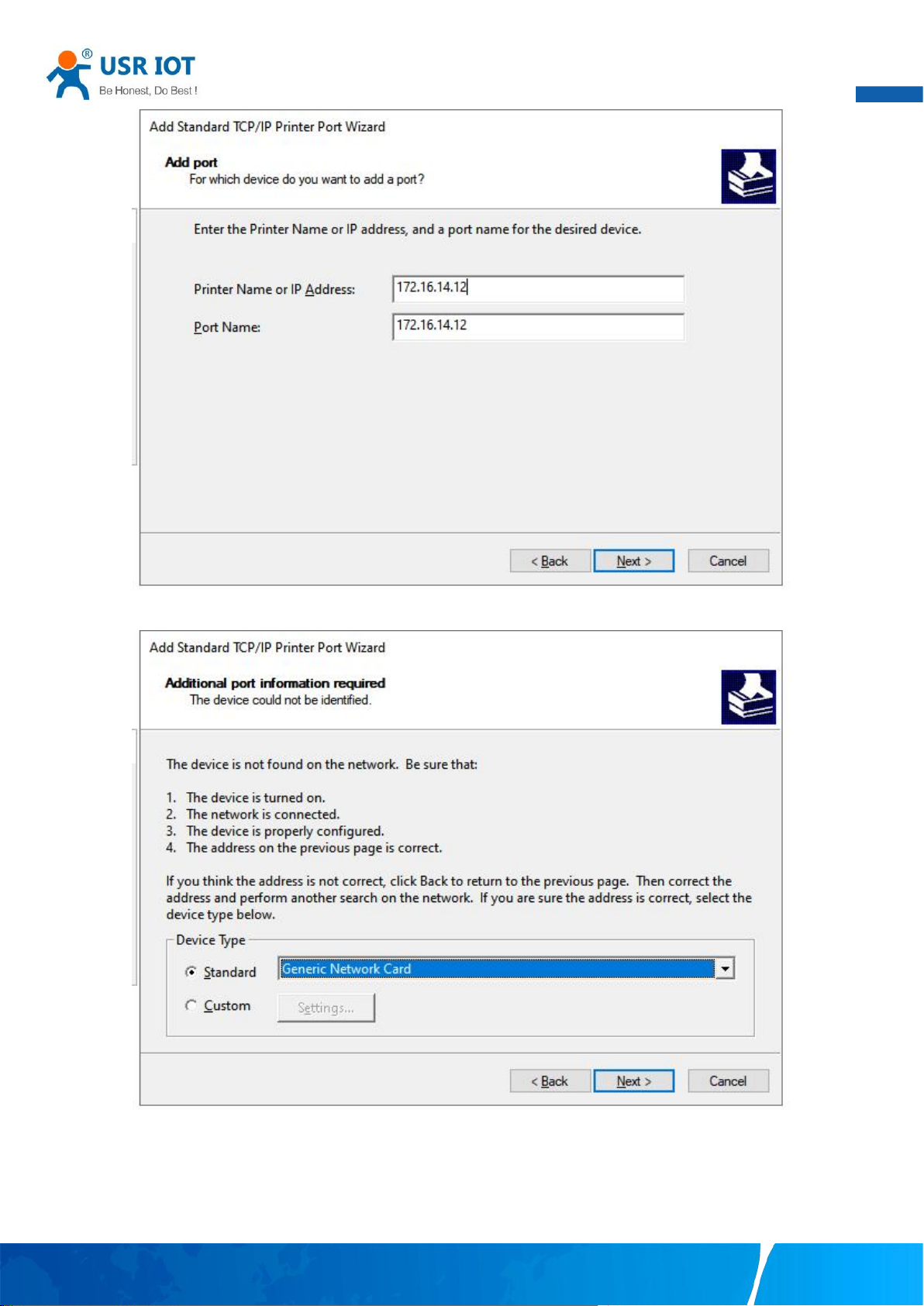
User Manual
81
Fig. 108 Serial printer setting wizard 1
Fig. 109 Serial printer setting wizard 1
Your TrustWorthy Industrial IoT Partner www.pusr.com
Page 83
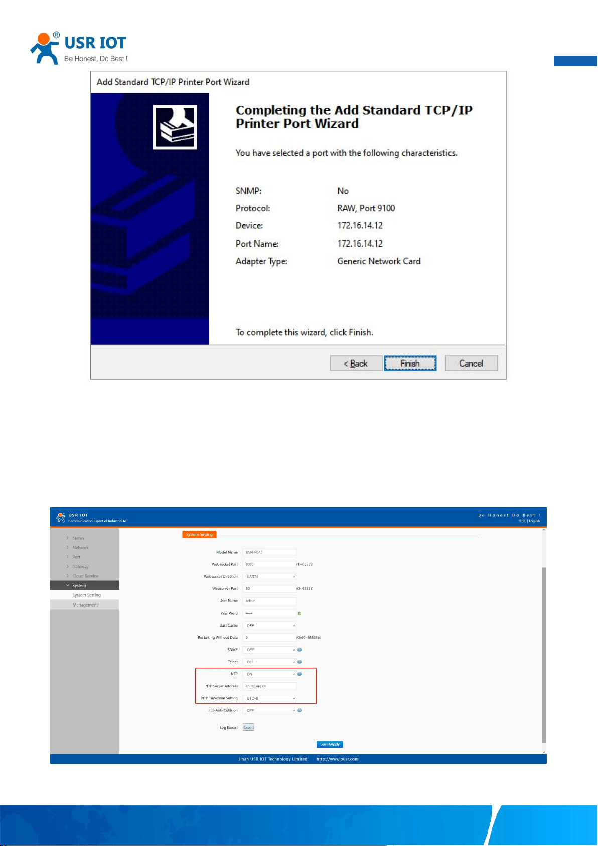
User Manual
82
Fig. 110 Serial printer setting wizard 1
7.7. NTP
If device is connected to the internet or to a local NTP server, the Date/time can be set automatically by enable NTP function. If this
option is chosen, the default value “cn.ntp.org.cn” should be shown in the NTP server field. User can select a proper Time Zone from
the dropdown box. If the N5X0 device is connected to the Internet and should connect to other servers over the Internet to get NTP
server, you will need to configure the DNS server in order to be able to resolve the host name of the NTP server.
Fig. 111 NTP settings
Your TrustWorthy Industrial IoT Partner www.pusr.com
Page 84
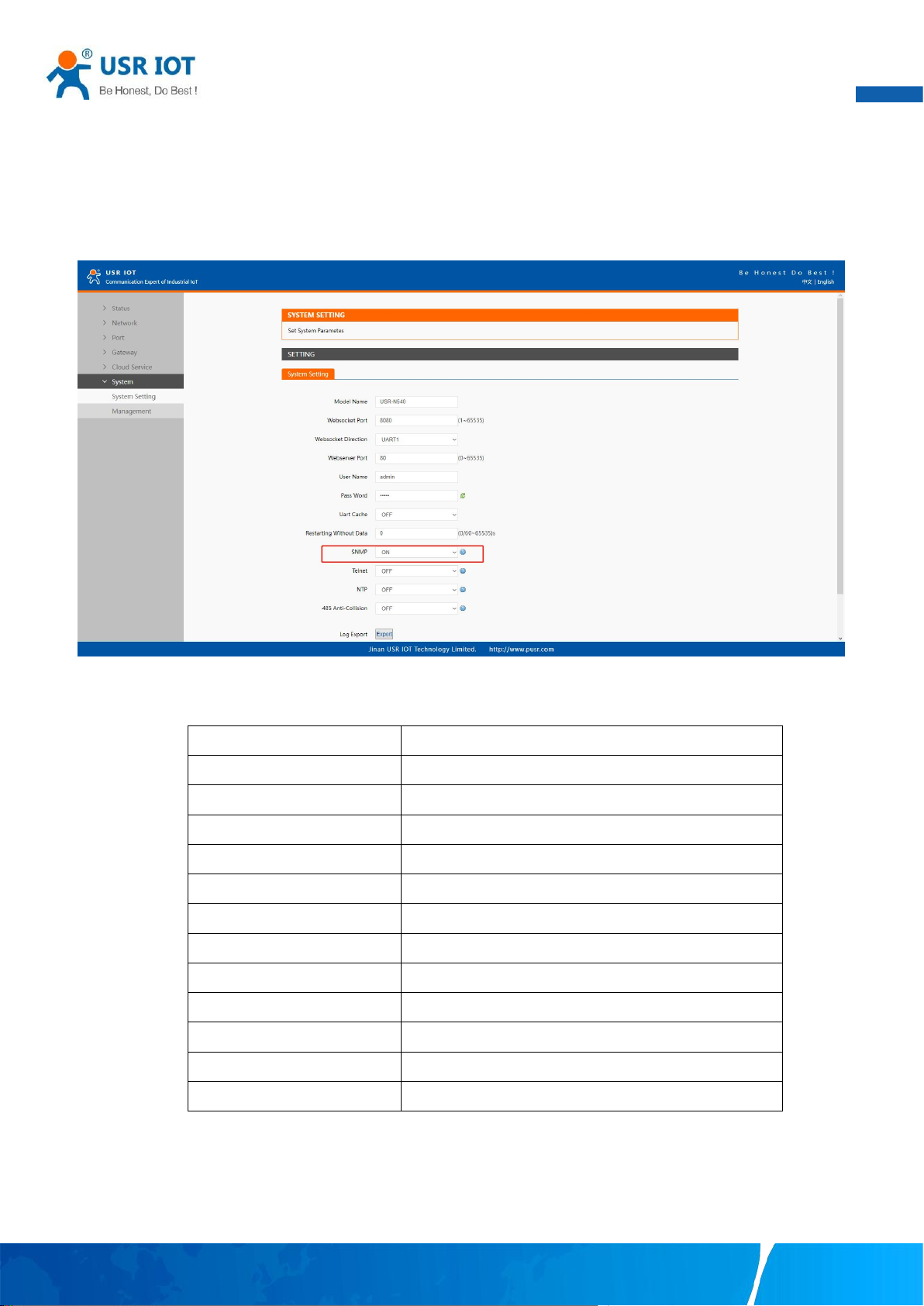
User Manual
83
Item
OID
IP address
.1.3.6.1.2.1.4.20.1.1.172.16.14.12
Subnet mask
.1.3.6.1.2.1.4.20.1.3.172.16.14.12
Preferred DNS
.1.3.6.1.2.1.12.5.0
Alternate DNS
.1.3.6.1.2.1.12.6.0
Gateway
.1.3.6.1.2.1.4.21.1.1.172.16.14.12
Running time
.1.3.6.1.2.1.1.3.0
Port1
.1.3.6.1.2.1.13.1.0
Port2
.1.3.6.1.2.1.13.2.0
...
...
Port8
.1.3.6.1.2.1.13.8.0
Firmware version
.1.3.6.1.2.1.12.1.0
Hardware version
.1.3.6.1.2.1.12.2.0
7.8. SNMP
The Simple Network Management Protocol (SNMP) is used by network management software to monitor devices in a network,
to retrieve network status information of the devices, and to configure network parameters of the devices.
To make the device’s information available for public viewing/editing, you can enable the SNMP function by checking the Enable box.
The supported SNMP Version:v1/v2c.The default SNMP Community Strings (or passphrases) is “admin”.
Fig. 112 Enable SNMP agent
Table 24 PUSR OID list
Your TrustWorthy Industrial IoT Partner www.pusr.com
Page 85
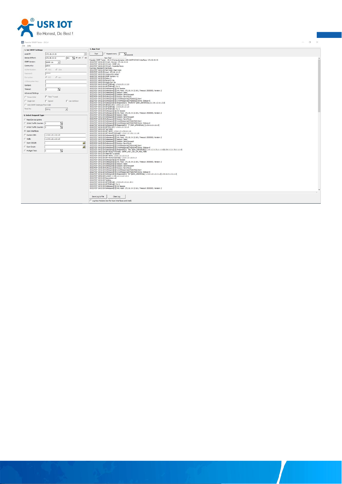
User Manual
84
Fig. 113 SNMP test
Your TrustWorthy Industrial IoT Partner www.pusr.com
Page 86
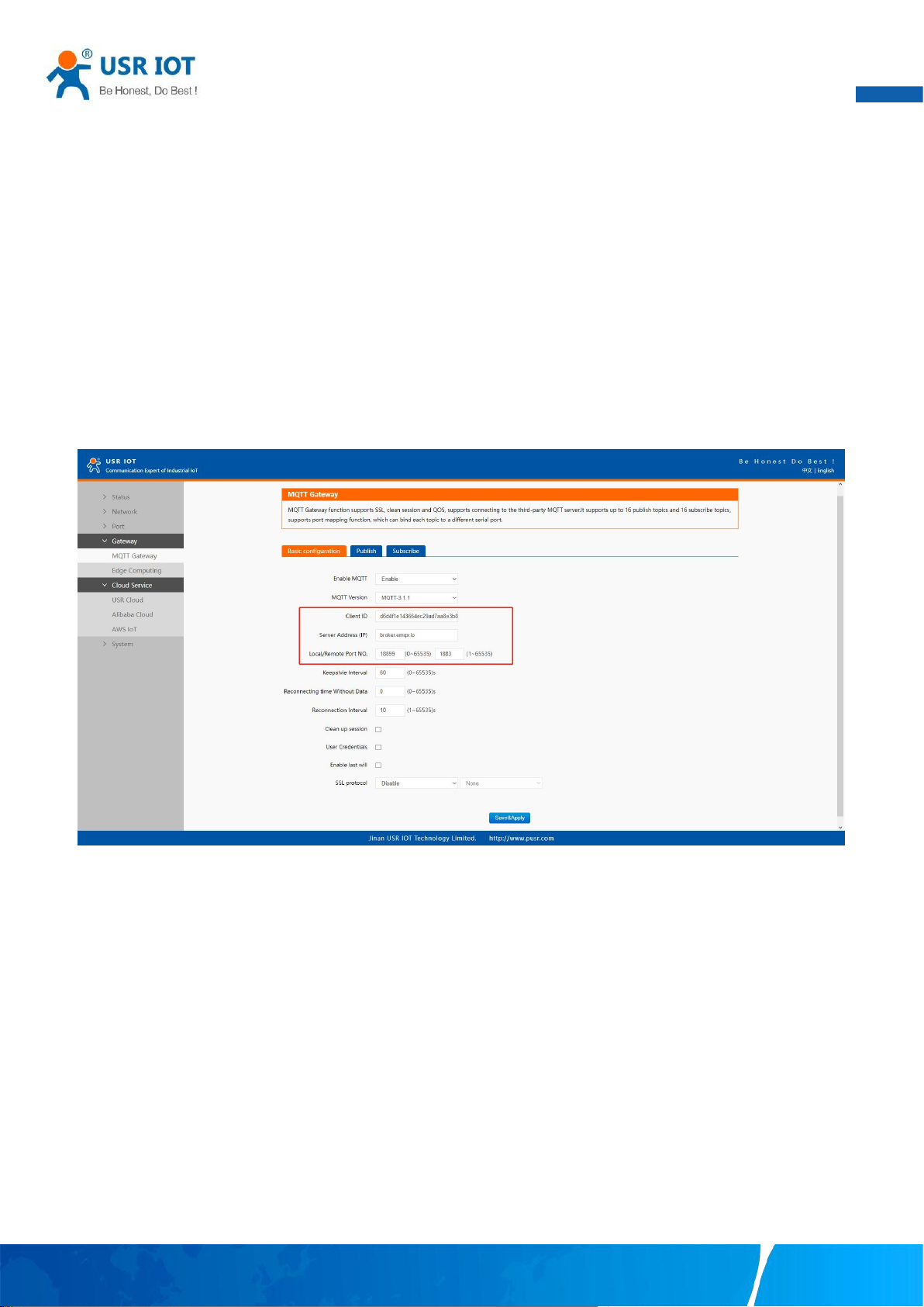
User Manual
85
8. MQTT gateway
Although the MQTT protocol has been around for nearly three decades, the design of the protocol makes it ideal for IIoT (Industrial
Internet of Things) applications, the latest trend in automation engineering. This is particularly true for applications that stress “active
notification,” in which devices provide data only when needed, as opposed to “passive notification,” in which devices are polled at
regular intervals. MQTT’s broker/client design eliminates the need for all devices in the system to be online at the same time. The
clients (i.e., “devices” or “things”) communicate directly with the broker, which plays the role of middleman to pass messages back
and forth between clients.
8.1. Basic settings
When configuring the Broker information,Client ID, Host, and Port are already filled in by default. You can also modify it by yourself
based on the actual Broker information. We will use Free Public MQTT Server provided by EMQX Cloud as the MQTT server address
for quick testing.
Fig. 114 MQTT broker setting
If your broker has enabled user authentication, you can fill in the information of Username and Password in the configuration item.
Your TrustWorthy Industrial IoT Partner www.pusr.com
Page 87
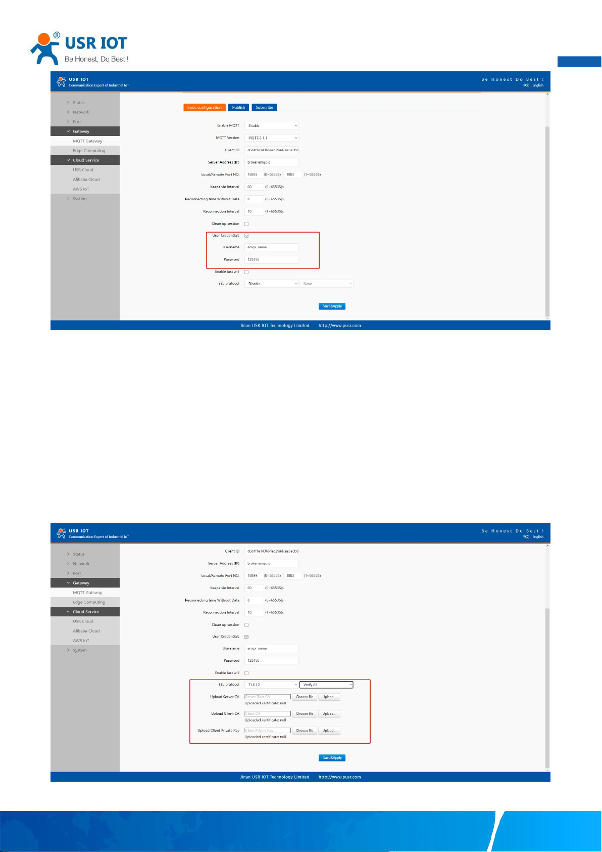
86
Fig. 115 User credential
User Manual
When you need to enable SSL/TLS authentication, you need to set the SSL/TLS configuration item. The two versions,TLS 1.0 and TLS
1.2 are provided. If SSL/TLS is selected, certificate configuration can be performed. If it is a one-way connection, you only need to
select your CA File. If it is a two-way authentication, you also need to select to configure Client Certificate File and Client key file. Click
the choose file button on the far right to select the certificates you have generated.
Uploads a Certificate Authority (CA) file. A Certificate Authority (CA) is an entity that issues digital certificates. A digital certificate
certifies the ownership of a public key by the named subject of the certificate.
Uploads a client certificate (cert) file. A certificate file is a type of digital certificate that is used by client systems to make
authenticated requests to a remote server.
Uploads a private key file.
Fig. 116 SSL/TLS connection
Your TrustWorthy Industrial IoT Partner www.pusr.com
Page 88
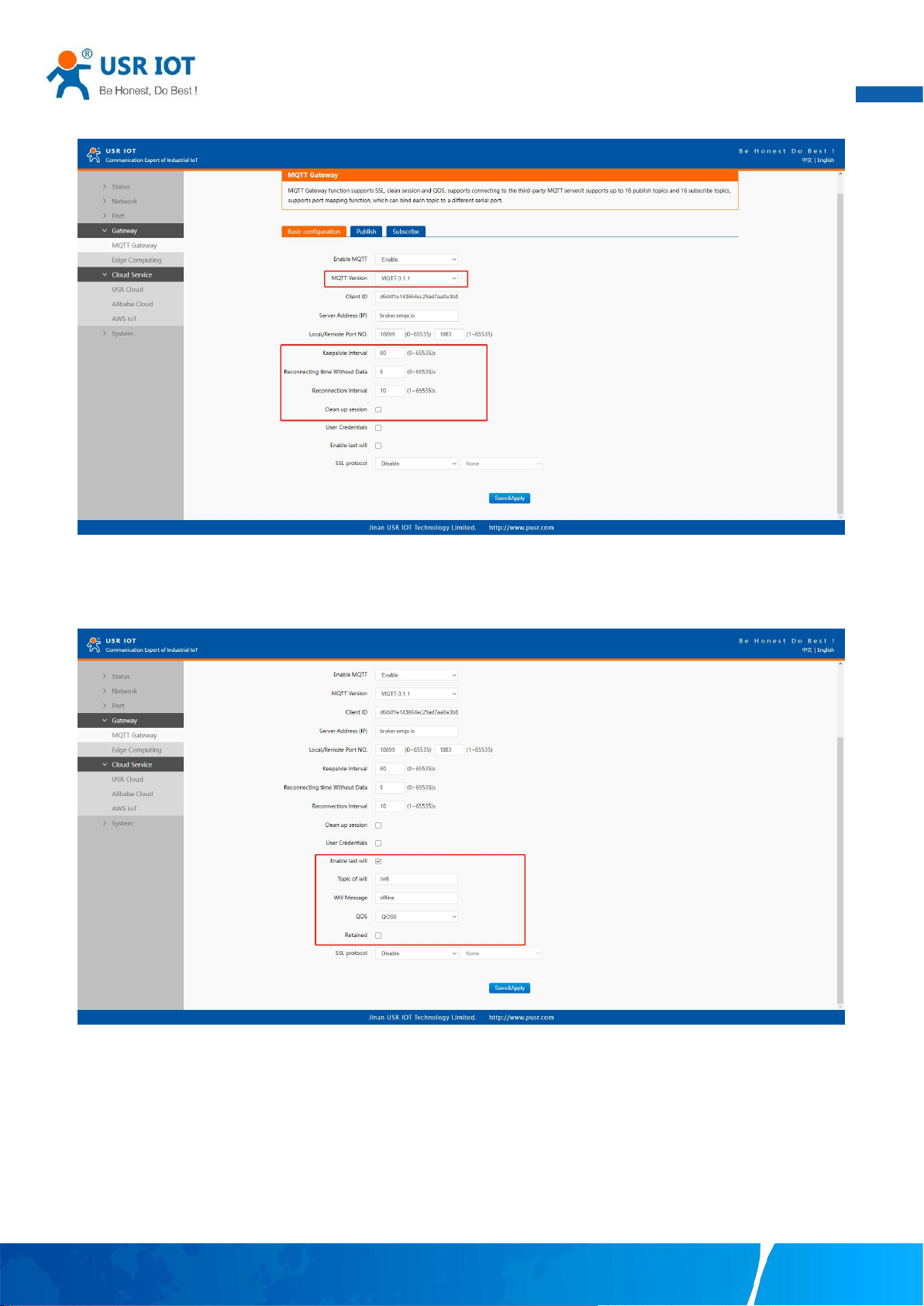
87
you can configure KeepAlive, Clean Session, Auto Reconnect, MQTT Version, etc.
User Manual
Fig. 117 Advanced configuration
You can configure the Will Message. The values of Last-Will-QoS and Last-Will-Retain are filled with 0 and False by default. When
you enter the values of Last-Will-Topic and Last-Will-Payload, you can complete the configuration of Will Message.
Fig. 118 Last will message
After finishing configuring the basic settings, please scroll down to the bottom of the page and click on "Save & Apply" button to save
all the changes that you have made. All configurations take effect after a system reboot. In this case we only finish the follow
parameters setting.
Your TrustWorthy Industrial IoT Partner www.pusr.com
Page 89
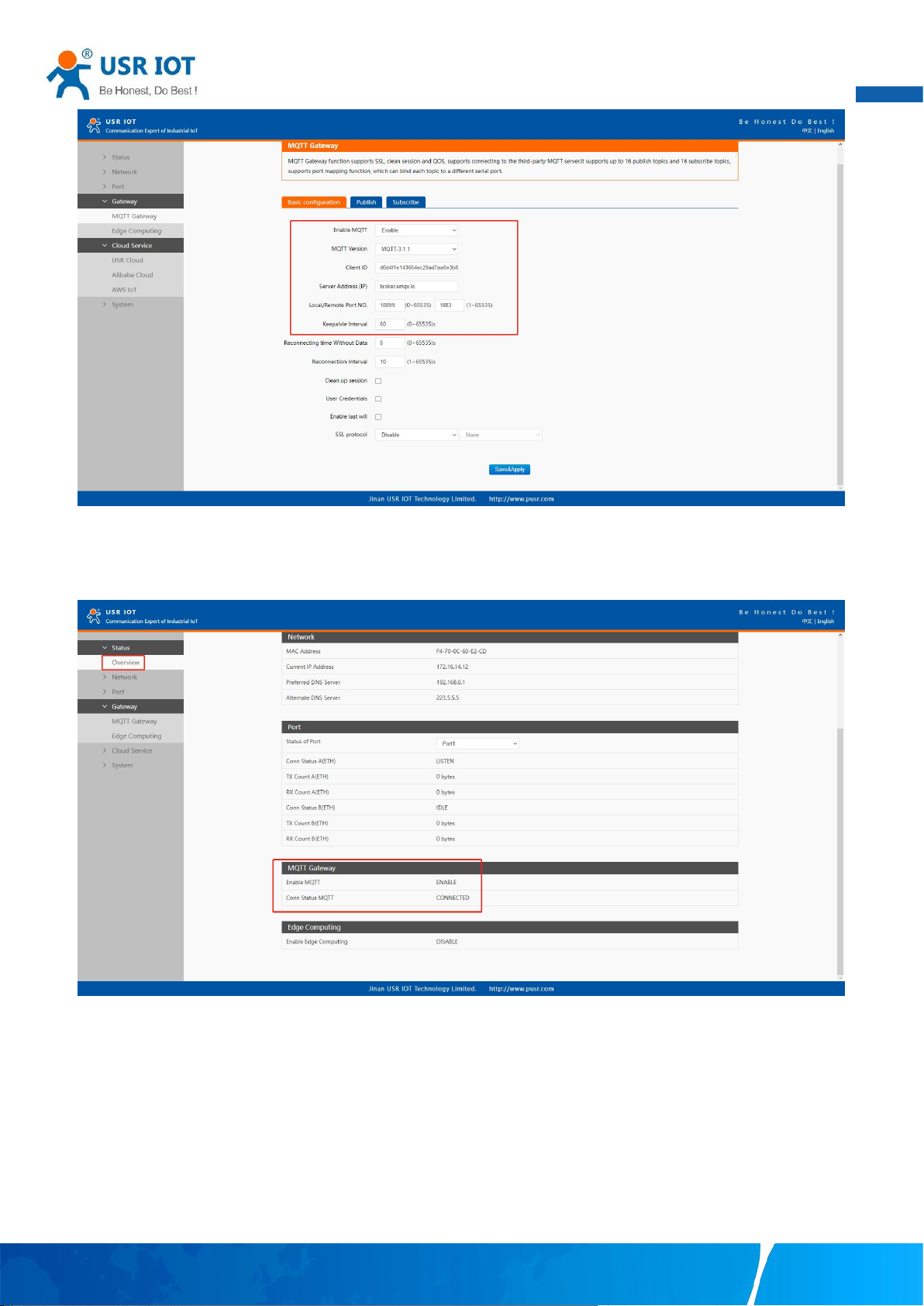
88
Fig. 119 EMQX broker connection
User Manual
To view the status of the device, choose Status>Overview, the device is in the CONNECTED state, the connection to IoT Hub is
successful, and publishing and subscribing operations can be performed.
Fig. 120 MQTT connection status
8.2. Publishing a message
8.2.1. MQTT.fx tool introduction
MQTT.fx is a mainstream MQTT desktop client. Compatible with Windows, macOS, and Linux, it can quickly verify whether it is
possible to connect to IoT Hub and publish or subscribe to messages. MQTT.fx in this article refers to version 1.7.1 without special
instructions.
The main page is shown in the figure below. The top part is the MQTT Broker connection address bar and its connection
configuration. The following function Tabs include Publish column, Subscribe column, Scripts column, Broker Status column, Log
Your TrustWorthy Industrial IoT Partner www.pusr.com
Page 90
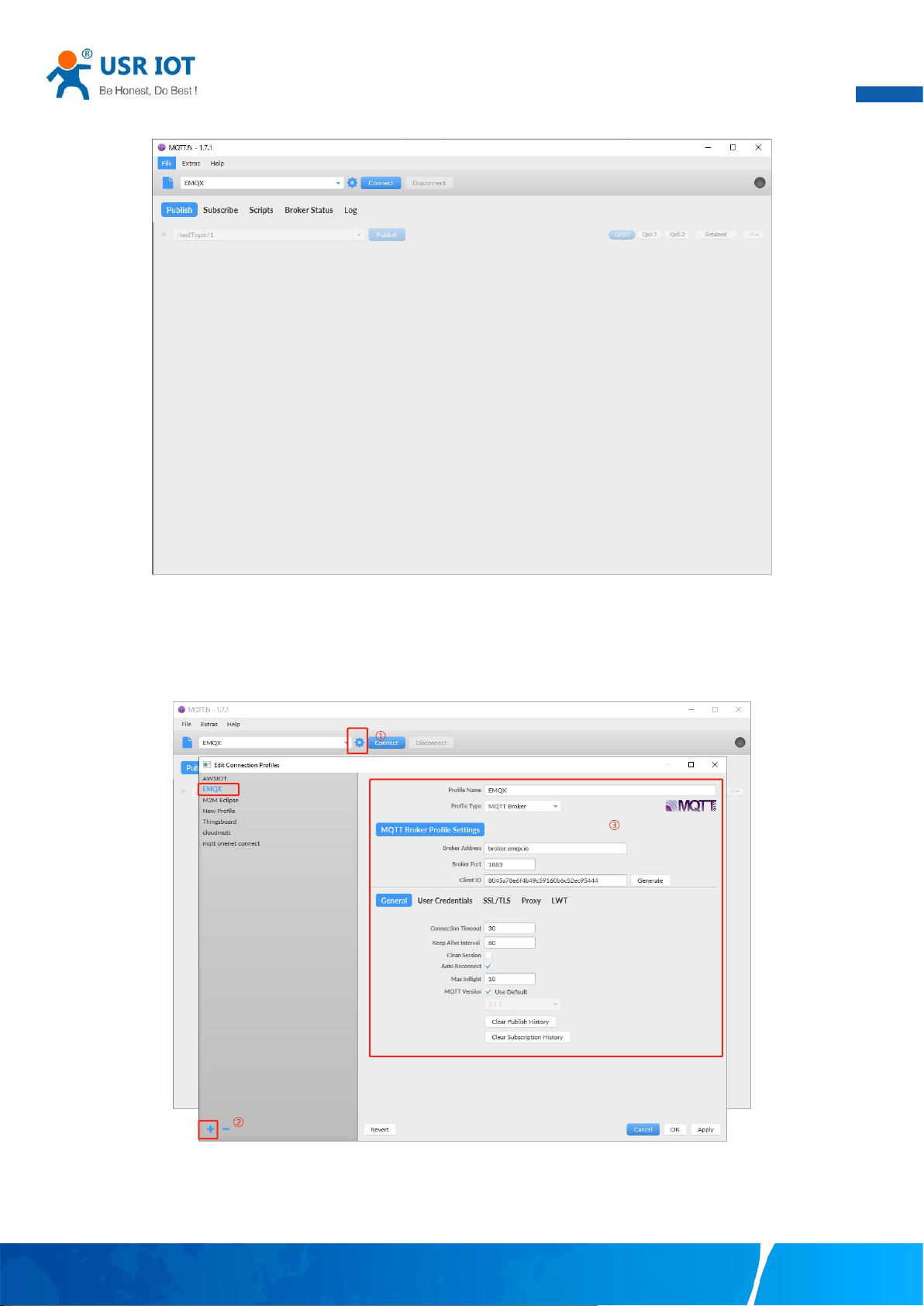
89
column for log information control.
User Manual
Fig. 121 MQTT.fx main page
First, the MQTT client and Broker need to establish a connection to communicate. Click the configuration icon on the right side of the
input box in the connection address bar to enter the specific connection configuration. Select the Profile Type as MQTT Broker. Fill
in broker.emqx.io for Broker Address and 1883 for Broker Port, as shown in the figure below:
Fig. 122 Connection Profiles
Click OK to confirm the configuration, return to the main interface, and click Connect. It can be seen that the indicator on the right
side turns to green, indicating that the current connection is successful, as shown in the following figure:
Your TrustWorthy Industrial IoT Partner www.pusr.com
Page 91
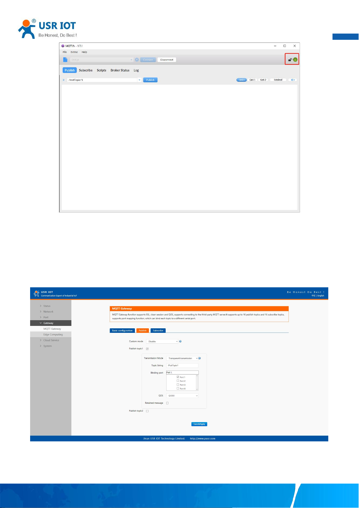
User Manual
90
Fig. 123 Successful connection
8.2.2. Transparent transmission
In the Publish field, select Publish topic1, enter the topic, bind to the Port1, select Qos 0, uncheck retained message. We use the
/PubTopic1 as an example to describe the process. After finishing configuring the Publish topic1, please scroll down to the bottom of
the page and click on "Save & Apply" button to save all the changes that you have made. All configurations take effect after a system
reboot.
Fig. 124 Add Publish topic
Click to enter the Subscribe Tab to enter /PubTopic1 in the topic box. Then, select a QoS level, click the Subscribe button, and the list
of subscribed topics will appear on the left. The current number of subscribed topics is 0, as shown in the following figure:
Your TrustWorthy Industrial IoT Partner www.pusr.com
Page 92
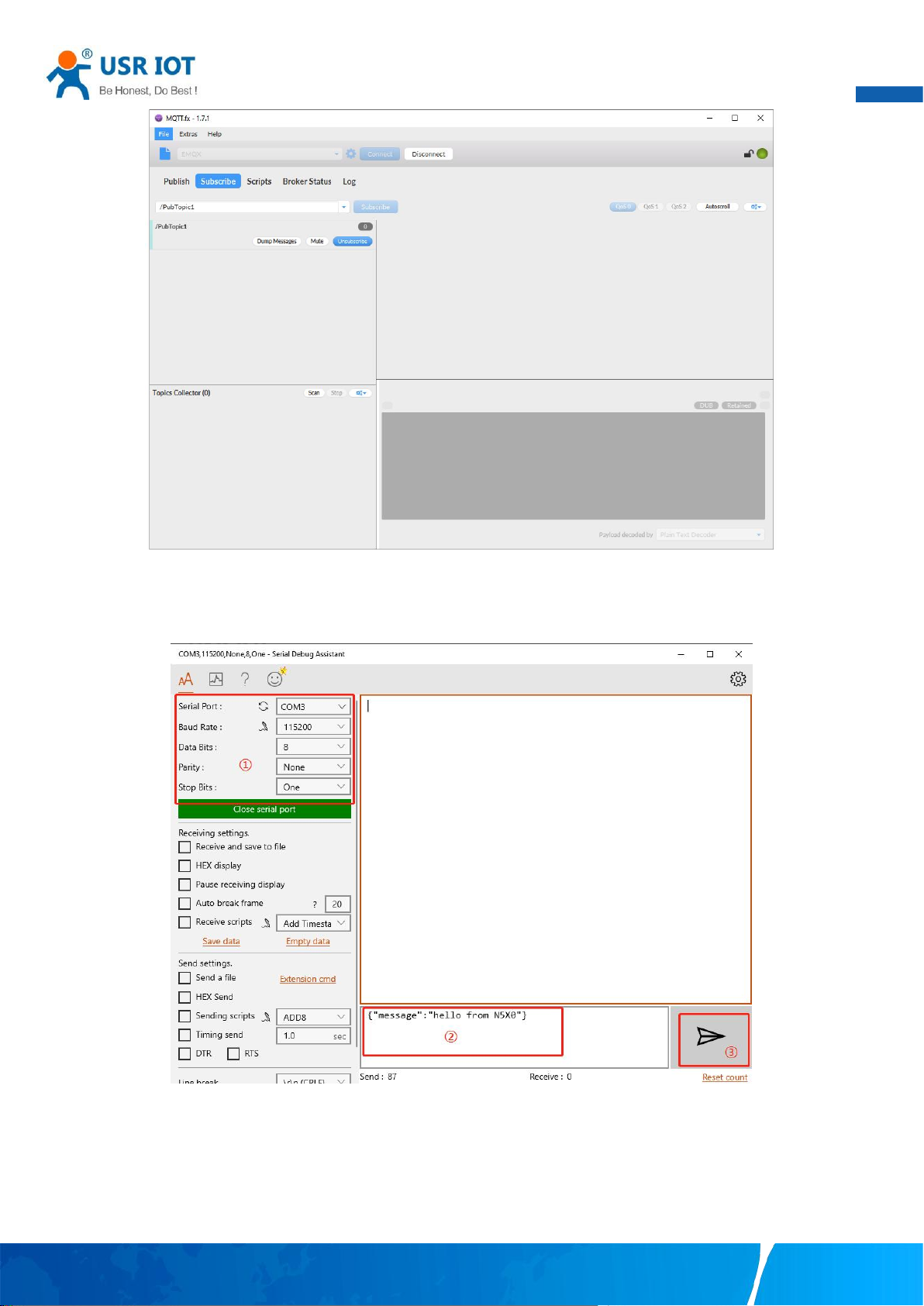
User Manual
91
Fig. 125 Subscribe to the N5X0 topic
Launch serial debug assistant on PC, and open COM Port with the N5X0’s serial default settings as below:
Fig. 126 Serial debug assistant setting
Click send button. On the MQTT.fx page, you will receive a message from the cloud that was sent from the N5X0. For Payload
decoded by select “JSON Pretty Format Decoder” to show the message.
Your TrustWorthy Industrial IoT Partner www.pusr.com
Page 93
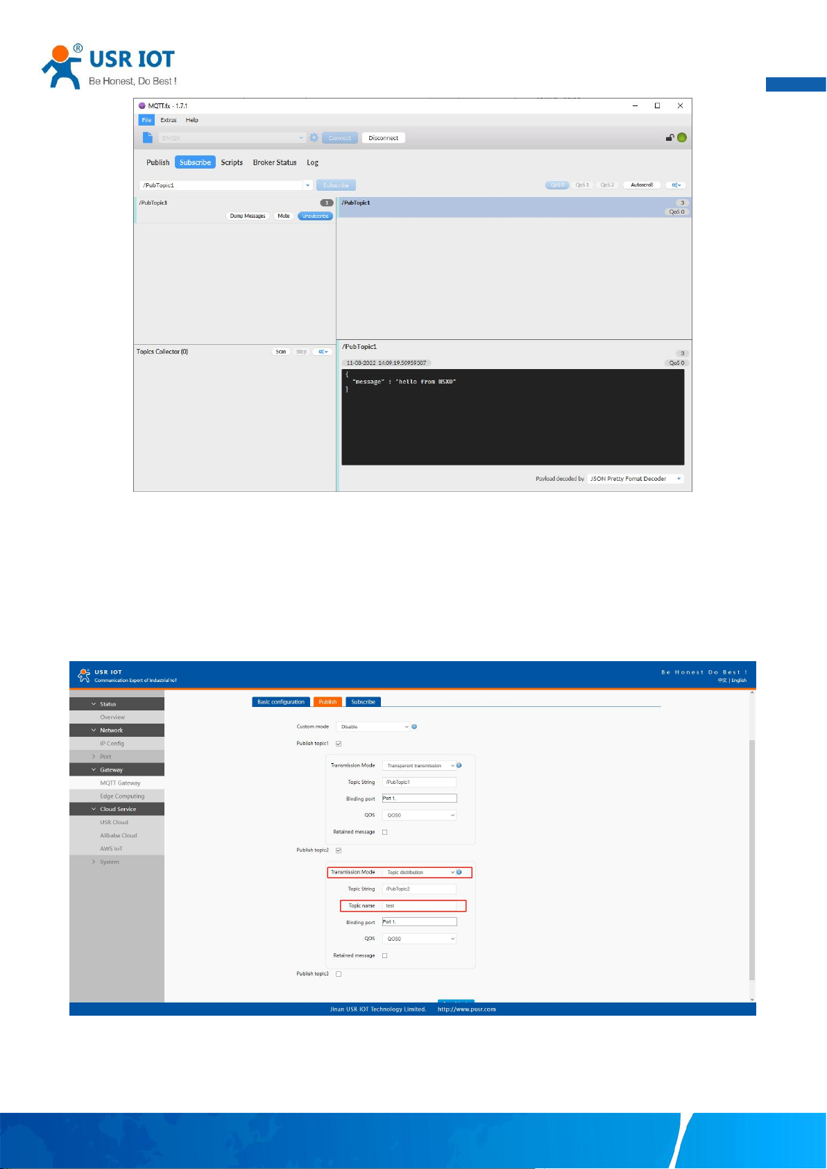
User Manual
92
Fig. 127 Receive message from N5X0
8.2.3. Topic distribution
In the Publish field, select Publish topic2, enter the topic, topic name, bind to the Port1, select Qos 0, uncheck retained message. We
use the /PubTopic2 as an example to describe the process. After finishing configuring the Publish topic2, please scroll down to the
bottom of the page and click on "Save & Apply" button to save all the changes that you have made. All configurations take effect after
a system reboot.
Fig. 128 Topic distribution mode
Click to enter the Subscribe Tab to enter /PubTopic2 in the topic box. Then, select a QoS level, click the Subscribe button, and the list
of subscribed topics will appear on the left. The current number of subscribed topics is 0, as shown in the following figure:
Your TrustWorthy Industrial IoT Partner www.pusr.com
Page 94
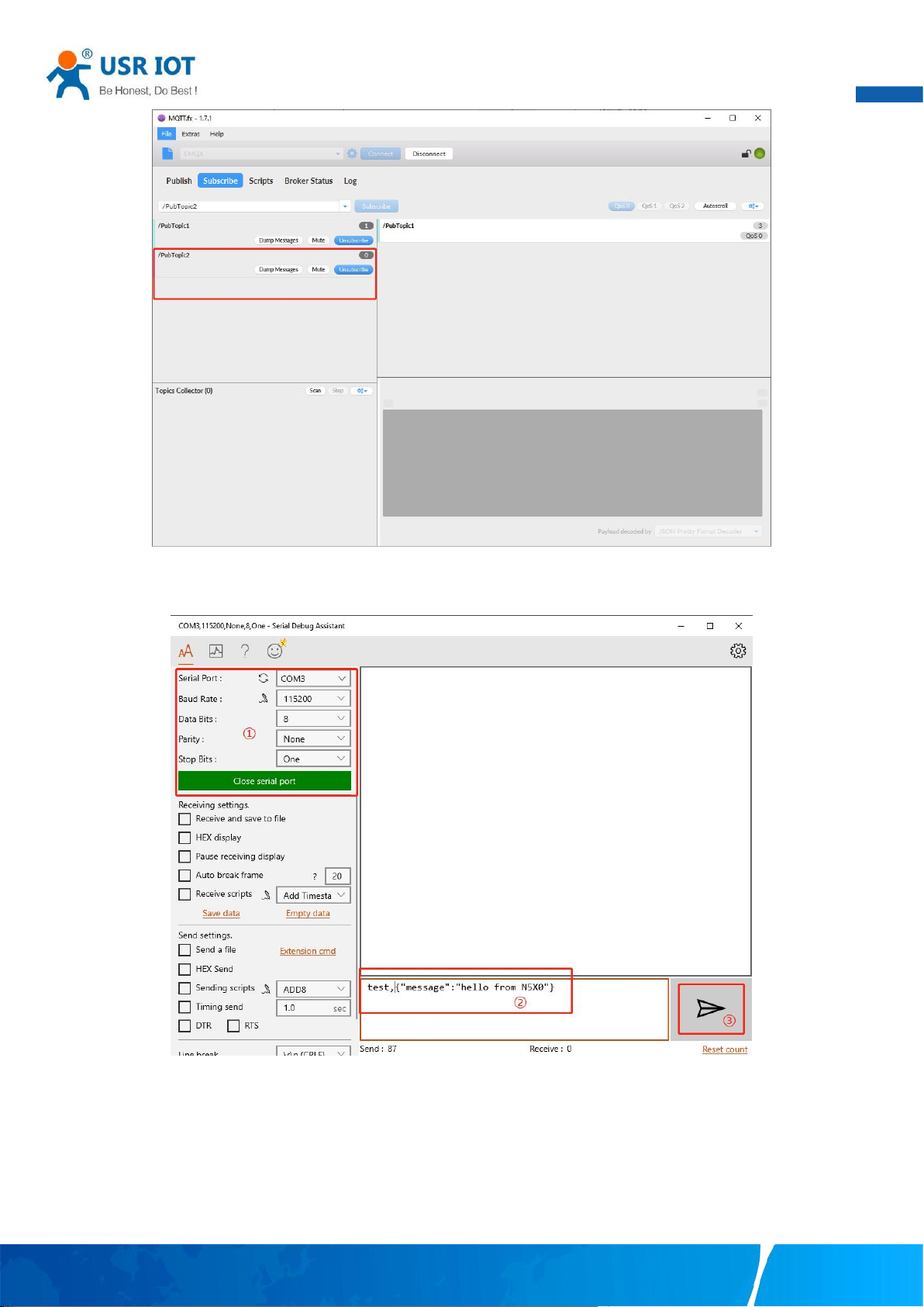
User Manual
93
Fig. 129 Subscribe to the N5X0 topic
Launch serial debug assistant on PC, and open COM Port with the N5X0’s serial default settings as below:
Fig. 130 Serial debug assistant setting
Enter the correct serial data format test,{"message":"hello from N5X0"}, Click send button. On the MQTT.fx page, you will receive a
message from the cloud that was sent from the N5X0.
Your TrustWorthy Industrial IoT Partner www.pusr.com
Page 95
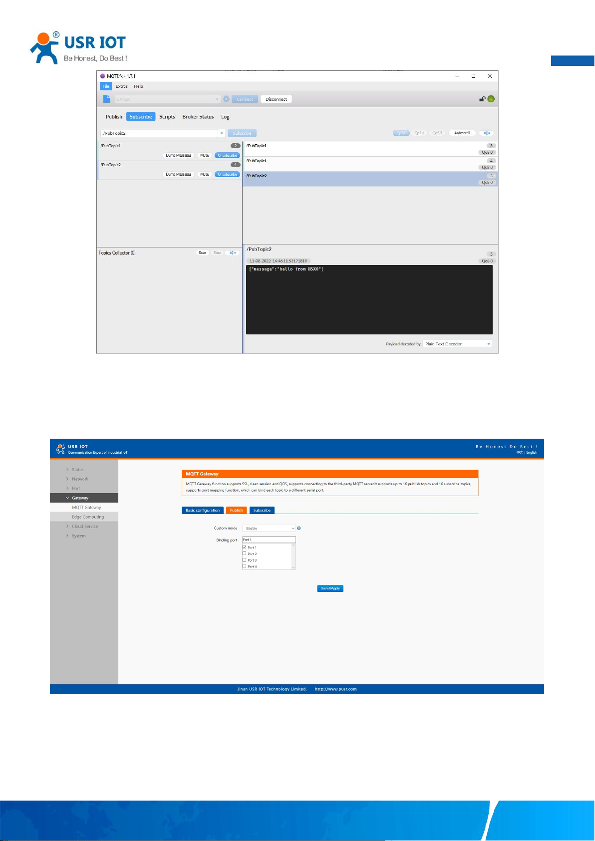
User Manual
94
Fig. 131 Receive message from N5X0
8.2.4. Custom mode
In the Publish field, select Custom mode, bind to the Port1. Click on "Save & Apply" button to save all the changes that you have made.
All configurations take effect after a system reboot.
Fig. 132 Custom mode
Click to enter the Subscribe Tab to enter /PubTopic3 in the topic box. Then, select a QoS level, click the Subscribe button, and the list
of subscribed topics will appear on the left. The current number of subscribed topics is 0, as shown in the following figure:
Your TrustWorthy Industrial IoT Partner www.pusr.com
Page 96
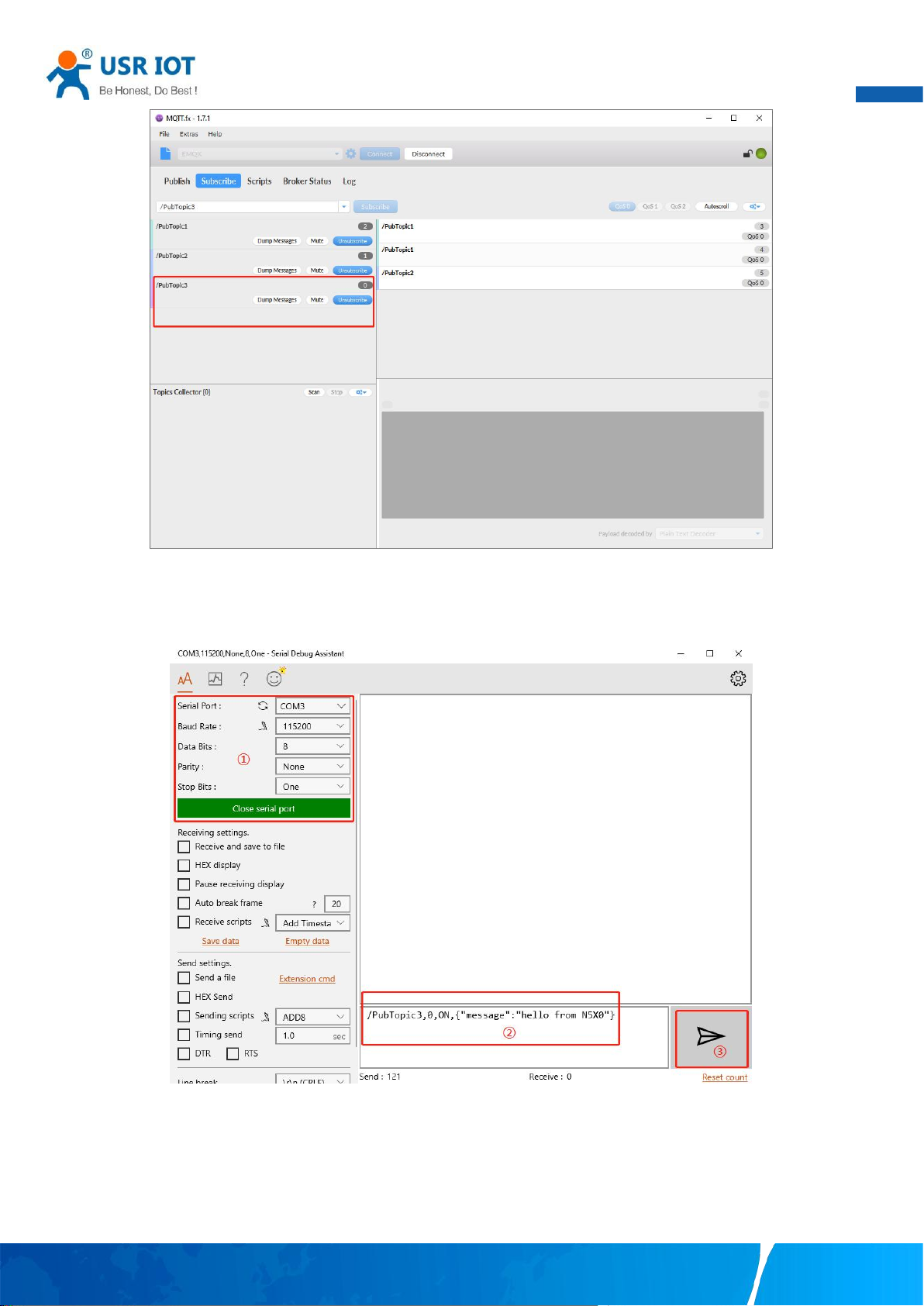
User Manual
95
Fig. 133 Subscribe to the N5X0 topic
Launch serial debug assistant on PC, and open COM Port with the N5X0’s serial default settings as below:
Fig. 134 Serial debug assistant setting
Enter the correct serial data format /PubTopic3,0,ON,{"message":"hello from N5X0"}, Click send button. On the MQTT.fx page, you will
receive a message from the cloud that was sent from the N5X0.
Your TrustWorthy Industrial IoT Partner www.pusr.com
Page 97
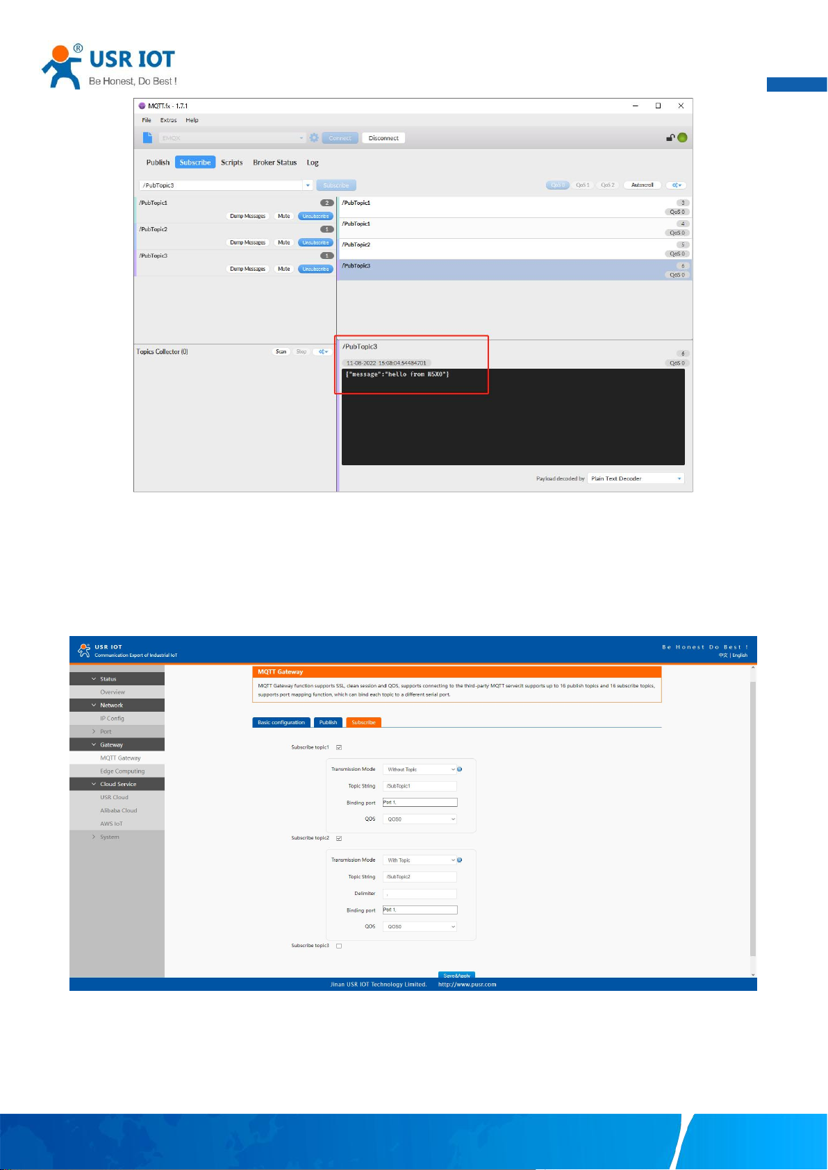
User Manual
96
Fig. 135 Receive message from N5X0
8.3. Subscribe to a topic
In the Subscribe field, select Subscribe topic1, enter the topic, bind to the Port1, select Qos 0. We use the /SubTopic1 as an example to
describe the process. After finishing configuring the Subscribe topic1, please scroll down to the bottom of the page and click on "Save
& Apply" button to save all the changes that you have made. All configurations take effect after a system reboot.
Fig. 136 Add subscribe topic
Click to enter the Publish Tab to enter /SubTopic1 in the topic box, and enter the message of "hello world" in the message input box,
select a QoS level, and click Publish to publish the message, as shown in the following figure:
Your TrustWorthy Industrial IoT Partner www.pusr.com
Page 98
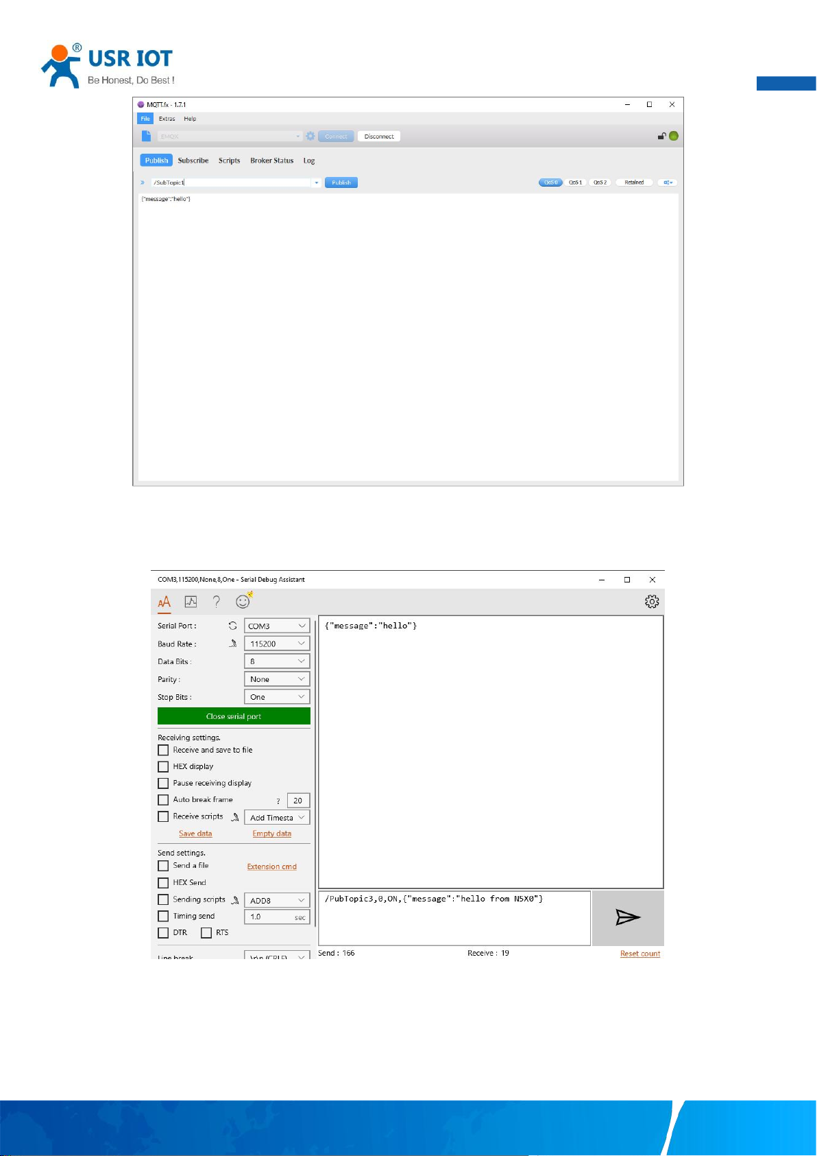
User Manual
97
Fig. 137 Publish message to N5X0
Click Publish to send the messages and return to the serial debug assistant. We can find that the serial port has received the message,
as shown in the following figure:
Fig. 138 Receive message from cloud
Your TrustWorthy Industrial IoT Partner www.pusr.com
Page 99
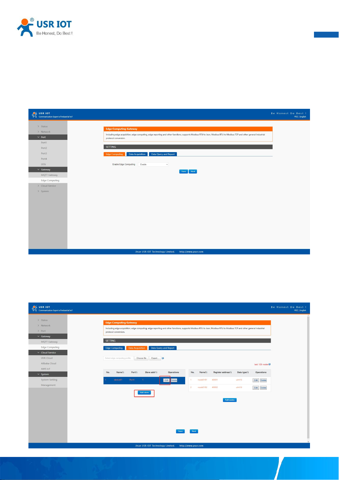
User Manual
98
9. Edge computing
The USR-N5X0 supports Modbus RTU Master for retrieving field site data from serial meters. After collecting data, users can convert
serial data to MQTT json format data, allowing users to get field site data. This two-in-one design reduces system complexity and the
amount of space required in the network topology, as well as overall installation time. In addition, you can extend the useful life of
legacy devices by connecting them to Ethernet and accessing the devices using a preferred protocol,TCP/UDP , HTTP , MQTT.
First,users need to enable edge computing function.
Fig. 139 Enable edge computing
9.1. Add modbus slave device
Connect serial device to the serial port of N5X0 gateway, and then configure the slave parameter on the data acquisition tab.
Click add slave to add a device, click edit to configure the device.
Fig. 140 Add a slave device
Your TrustWorthy Industrial IoT Partner www.pusr.com
Page 100
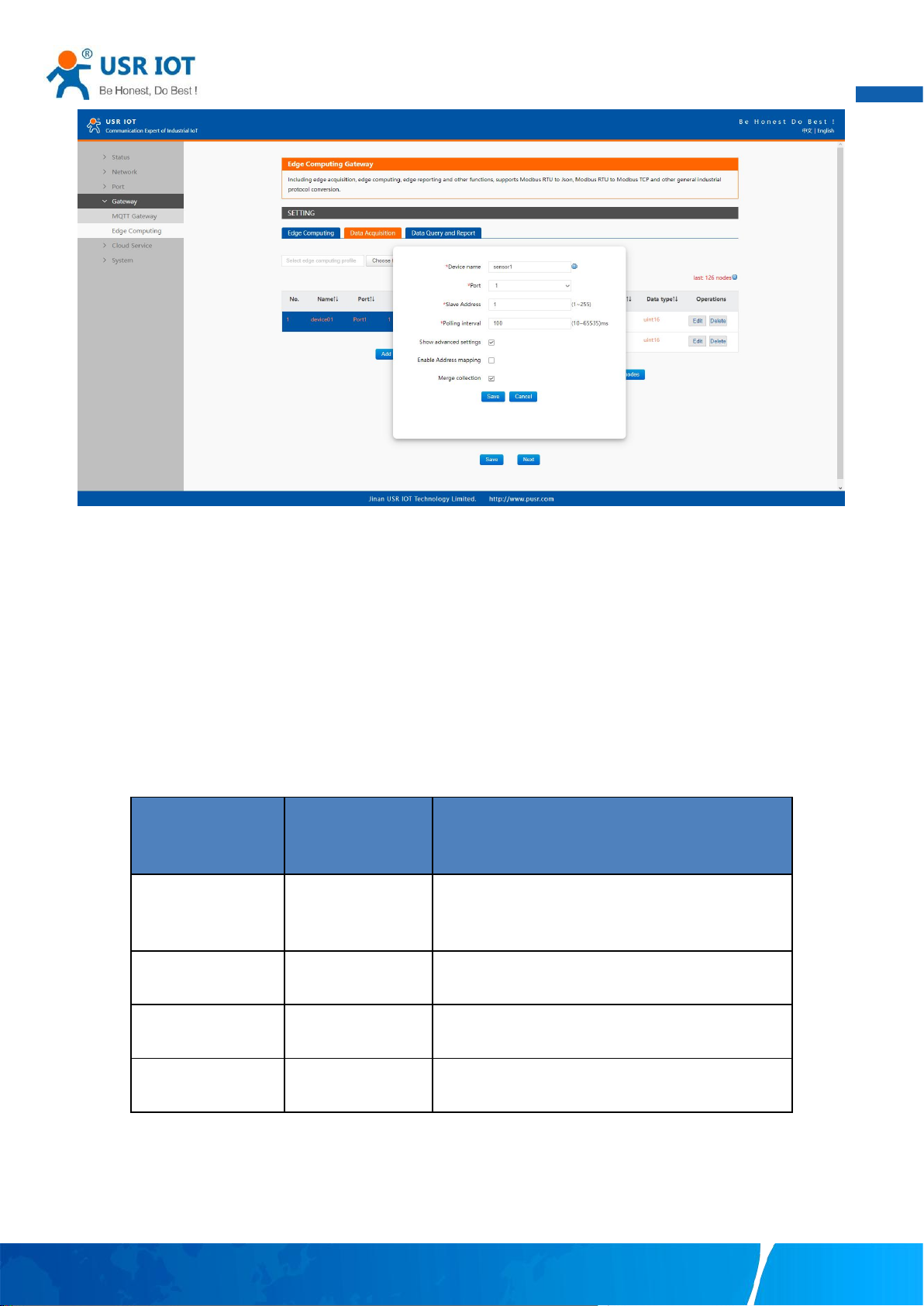
99
Fig. 141 Polling slave device configuration
Register type
Address range
Description
Coil points
00001 – 09999
Read, function code 0x1, bool values
Discrete inputs
10001 – 19999
Read only, function code 0x2, bool values
Input registers
30001 – 39999
Read only, function code 0x4, int,uint,float values
Holding registers
40001 – 49999
Read/Write, function code 0x3,int,uint,float values
User Manual
In the slave property, enter the device name, bind to the Port1, enter the slave address and polling interval, enable merge collection
function, the description of the configuration parameters on this interface is shown in table 18. We use the temperature and
humidity sensor1 as an example to describe the process. After finishing configuring the slave device, please scroll down to the bottom
of the page and click on "Save" button to save all the changes that you have made. All configurations take effect after a system
reboot.
9.2. Add modbus data points
9.2.1. Register type and offset
Table 25 Typical Register Tables
The Modbus register addressing starts with register 0, but some device manufacturers start with the number 1 in the device
documentation. In this case, the number minus 1 should give the correct register address. Offsets can be represented in different
ways. Sometimes as Hex values and sometime the offset will also contain the register type. For example Offsets in the Holding
Register range might start with a 4 such as 411001, in the SCADA this would be entered as 11001.
Your TrustWorthy Industrial IoT Partner www.pusr.com
 Loading...