

Page 1
USR-DR404 AT 指令集
1
USR-IOxx Series User Manual
Build a Smarter IoT world, Your Trustworthy Partner
Page 2

User Manual
Your TrustWorthy Industrial IoT Partner www.pusr.com
1
1. Introduction ....................................................................................................................................................... 2
1.1. Overview .............................................................................................................................................. 2
1.2. Ordering guide........................................................................................................................................ 2
1.3. Parameter specification ............................................................................................................................. 2
1.4. Dimension ............................................................................................................................................. 3
1.5. Status LEDs ........................................................................................................................................... 3
1.6. Physical interface .................................................................................................................................... 4
2. Modbus RTU Protocol.......................................................................................................................................... 4
2.1. Function code ......................................................................................................................................... 4
2.2. Modbus message format ............................................................................................................................ 4
2.3. RS485 parameters.................................................................................................................................... 5
2.4. Register for storing RS485 parameters .......................................................................................................... 5
2.5. Register for storing system parameters .......................................................................................................... 5
2.6. I/O register ............................................................................................................................................ 6
3. Combination of I/O modules ..................................................................................................................................... 6
3.1. Combination of extended I/O modules .......................................................................................................... 6
3.2. Combination of extended I/O modules and I/O host .......................................................................................... 7
4. Reset to factory settings ........................................................................................................................................... 7
5. Contact Us ......................................................................................................................................................... 8
Content
Page 3
User Manual
Your TrustWorthy Industrial IoT Partner www.pusr.com
2
1. Introduction
1.1. Overview
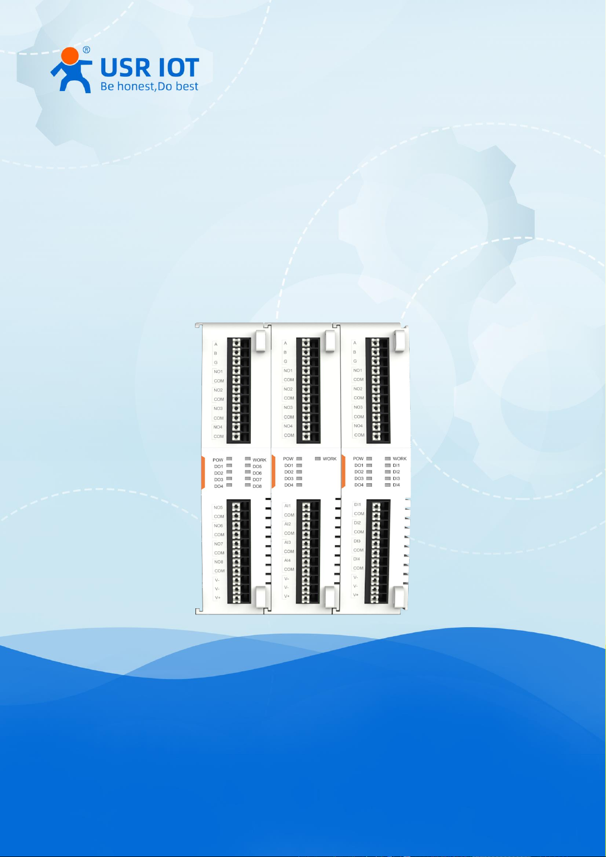
The USR-IOxx series controller are a brand-new generation of IO modules which support data acquisition and control
launched by USR. They adopt an expandable structure design, flexible matching, standard RS485 interface, and come with
standard Modbus RTU protocol which enables rapid application matching. The controllers are equipped with rich indicator
lights which can help users to determine the device status.
USR-IOxx series controllers have multiple models to choose from and can be flexibly combined according to different
on-sites needs. It can also be combined with USR-M100 and USR-M300 to provide rich and comprehensive features.
1.2. Ordering guide
Model
USR-IO4040
USR-IO0440
USR-IO0080
*USR-IO8000
Number of DI
4 0 0
8
Number of AI
0 4 0 0 Number of DO
4 4 8
0
Number of AO
0 0 0
0
Type of AI
/
Current
/
/
Signal range of AI
/
4~20mA
/
/
Voltage range of DI
9~36V
/ / 9~36V
Type of DO
Relay
Relay
Relay
/
Capability of DO
3A
3A
3A / Communication port
RS485
RS485
RS485
RS485
Support extendable
√ √ √
√
1.3. Parameter specification
Items
Description
Interface
RS485
Default: 9600, NONE, 8, 1
Options for band rate: 4800, 9600, 115200, 230400
Parity bit: NONE, EVEN, ODD
Data bits: 8
Stop bit(s): 1, 2
Physical
Specification
Dimensions
79.6*58*110(mm)
Installation
DIN rail mounting & Panel mounting
Status LEDs
POW
Steady on: Power supply is normal
Off: No power supply or abnormal power supply
WORK
Blinking: Power is on, and the device is ready. System is booted up and running
DO
Steady on: The channel output is activated
DI
Steady on: The channel is activated input signal
Power
2-pin socket
DC: 9~36V
Page 4
User Manual
Your TrustWorthy Industrial IoT Partner www.pusr.com
3
Temperature
Operation
temperature
-25℃ ~ +75℃
Storage
temperature
-40℃ ~ +105℃
Humility
Operation humility
5%~95% (non-condensing)
I/O
DI
Digital opto-isolated input (0 -2 V detected as logic low,9 -36 V detected as logic
high)
AI
Analog input 4-20mA
DO
Relays, the endurance is 100,000 operations.
DC contacts rating @R (at resistive load) 3A / 30V DC.
AC contacts rating @R (at resistive load) 3A / 250V AC, NO
Modbus
Slave address
Range: 1~255
Default: 1
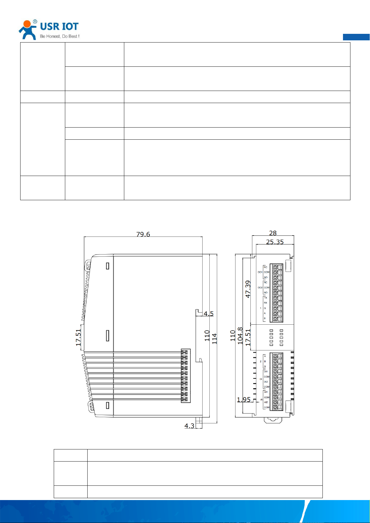
1.4. Dimension
1.5. Status LEDs
LED
Description
POW
Steady on: Power supply is normal
Off: No power supply or abnormal power supply
WORK
Blinking: Power is on, and the device is ready. System is booted up and running
Page 5
User Manual
Your TrustWorthy Industrial IoT Partner www.pusr.com
4
DO
Steady on: The channel output is activated
DI
Steady on: The channel is activated input signal
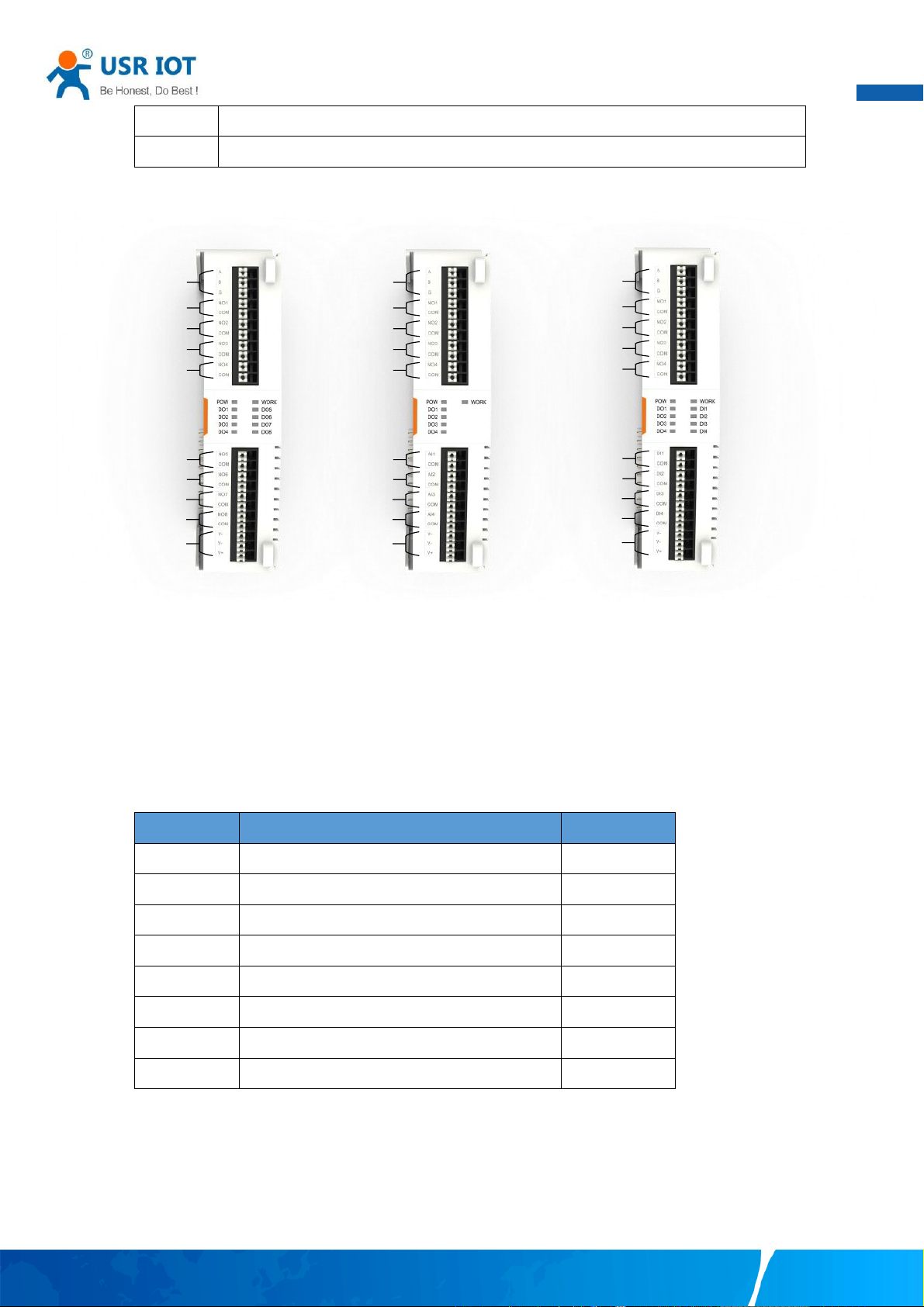
1.6. Physical interface
RS485
DO1
DO2
DO3
DO4
DO5
DO6
DO7
DO8
Power
9~36V
RS485
DO1
DO2
DO3
DO4
AI1
AI2
AI3
AI4
Power
9~36V
RS485
DO1
DO2
DO3
DO4
DI1
DI2
DI3
DI4
Power
9~36V
8DO 4AI+4DO 4DI+4DO
2. Modbus RTU Protocol
USR-IOxx series controller support standard Modbus RTU protocol. Users need to know some information about the
protocol.
2.1. Function code
Code (Hex)
Description
Data Access
01
Read Coil(s)
Bit access
02
Read Discrete Input(s)
Bit access
03
Read Single or Multiple Holding Register(s)
16-bit access
04
Read input status
16-bit access
05
Write Single Coil
Bit access
06
Write single holding register
16-bit access
0F
Write multiple coils
Bit access
10
Write Single or multiple holding registers
16-bit access
2.2. Modbus message format
Modbus RTU message contains query message and response message. Query message is from Master device to Slave
device, while the response message is from Slave device to Master device.
Query message (Hex):
Page 6
User Manual
Your TrustWorthy Industrial IoT Partner www.pusr.com
5
Device Address
Function Code
Starting Address
Quantity
Check Code
1 Byte
1 Byte
2 Bytes
2 Bytes
2 Bytes
01
03
00 00
00 02
C4 0B
Response message (Hex):
Device Address
Function Code
Data length
Data 1
Data 2
Check Code
1 Byte
1 Byte
2 Bytes
2 Bytes
2 Bytes
2 Bytes
01
03
04
00 01
00 02
2A 32
2.3. RS485 parameters
Name
Option(s)
Default
Baud rate
4800, 9600, 115200, 230400
9600
Data bits
8 8 Stop bit(s)
1,2
1
Parity bit
None, Even, Odd
None
2.4. Register for storing RS485 parameters
Register type: 4x means Holding Register.
Name
Register type
Register address (Dec)
Function code (Hex)
Bit(s)
Description
Baud rate
4x
0032~0033
03, 10
32 bits
Data bits
4x
0034
03, 06, 10
16 bits
Stop bit(s)
4x
0035
03, 06, 10
16 bits
Parity bit
4x
0036
03, 06, 10
16 bits
Example of reading and writing baud rate register:
Action
Read/write command
Response
Read baud rate
01 03 00 20 00 02 C5 C1
01 03 04 00 00 25 80 E1 03
Write band rate
01 10 00 20 00 02 04 00 01 C2 00 F1 17
01 10 00 20 00 02 40 02
Users need restart the USR-IOxx device to make the changed parameters take effect. Users can send reboot command or
power cycle device to restart it.
2.5. Register for storing system parameters
Name
Register type
Register address (Dec)
Function code (Hex)
Bit(s)
Description
Slave address
4x
0017
03,06
16
Default: 1
Reboot
4x
0016
06
16
Data field: 0xFF00
SN
4x
0112~0121
03
10 Words
Length: 20 strings
Filter time for DI
4x
0048~0055
03,10
16
Range: 10~65535ms
Examples:
Action
Read/Write command
Response
Page 7
User Manual
Your TrustWorthy Industrial IoT Partner www.pusr.com
6
Reboot
01 06 00 10 FF 00 C9 FF
01 06 00 10 FF 00 C9 FF
Read slave address:
01 03 00 11 00 01 D4 0F
01 03 02 00 01 79 84
Read SN
01 03 00 70 00 0A C4 16
01 03 14 0B D7 0C 9E 0D 02 0C A1 0B D9 0C 3E 0B D6 0D 0B
0D 69 0B D7 34 B8
2.6. I/O register
Name
Register type
Register address (Dec)
Function code (Hex)
Bit(s)
Description
DI
1x
0000~0007
02
1 bit
AI
3x
0000~000F
04
32 bits
DO
0x
0000~0007
01, 05, 0F
1 bit
ON: 0xFF00
OFF: 0x0000
AI: Float 32
Examples:
I/O Action
Read/Write command
Response
Write DO
01 05 00 00 FF 00 8C 3A
01 05 00 00 FF 00 8C 3A
Read DI
01 02 00 00 00 01 B9 CA
01 02 01 00 A1 88
Read AI
01 04 00 00 00 02 71 CB
01 04 04 00 00 00 00 FB 84
3. Combination of I/O modules
The USR-IOxx series controller support the combination of different models, and users can choose different combinations
according to their needs. The products come up with an extension guide rail and extension interface component. Just push
two modules together to achieve module connection.
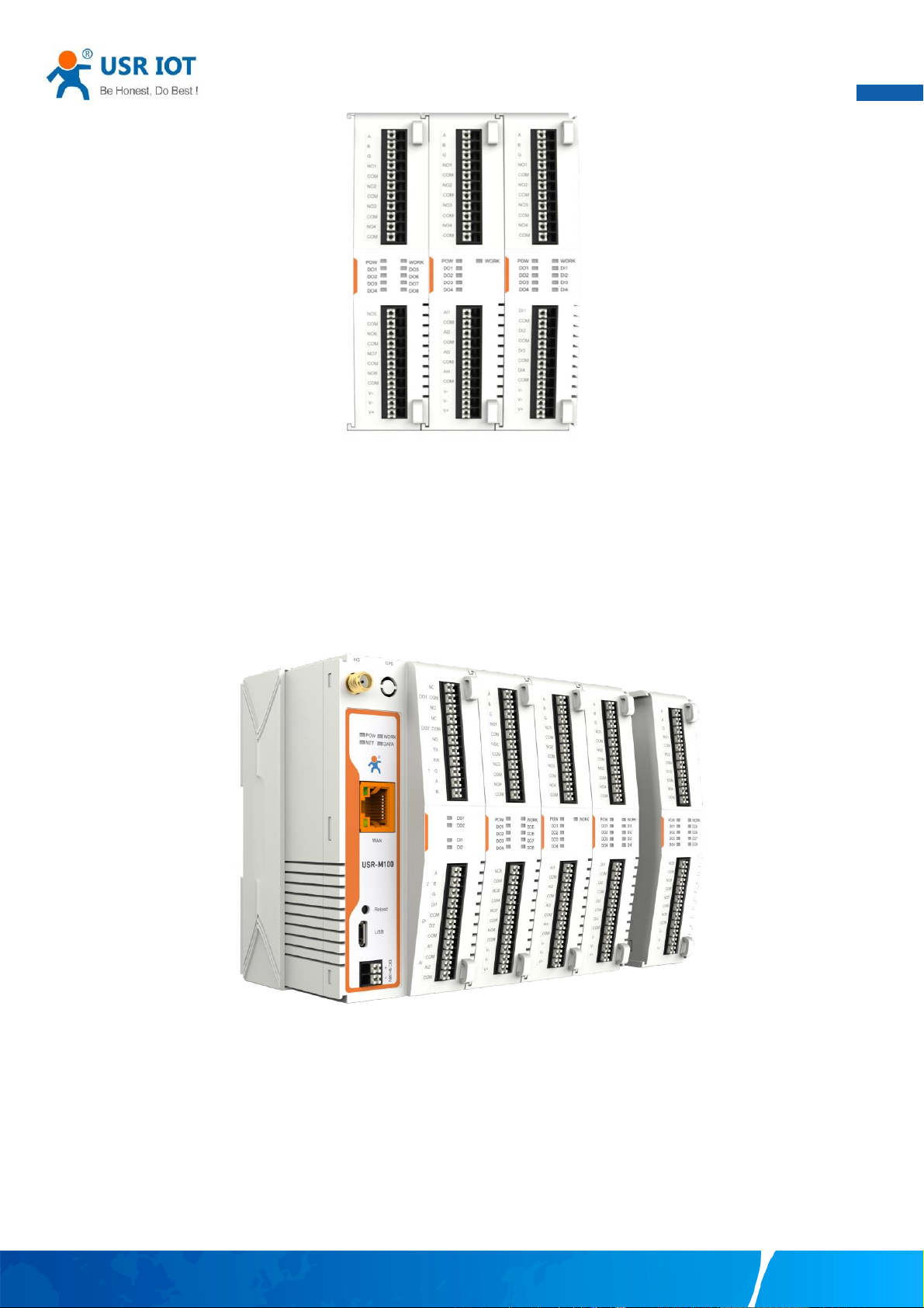
3.1. Combination of extended I/O modules
Using this combination, the leftmost I/O module functions as the first slave. It only needs to power the first slave to
implement all I/O modules. Additionally, access to all I/O modules can be achieved through the RS485 serial port of the first
slave and this design can reduce wiring requirements.
The principle of assigning slave address is to assign them from left to right. Users just need to set the first module’s slave
address, and the address of the modules on the right are incremented by one based on the left module. For example, if the
slave address of the first I/O module on the left is 10, then the second one is 11, and the third one is 12, and so on.
Page 8
User Manual
Your TrustWorthy Industrial IoT Partner www.pusr.com
7
3.2. Combination of extended I/O modules and I/O host
USR-IOxx series controllers can be combined with USR-M100 and USR-M300 to provide rich and comprehensive features.
After the I/O modules is connected to the host, the slave address and register address are uniformly allocated by the host,
and power supply and communication are also provided by the host. Power supply and communication cable do not need to
be connected. And all the I/O interface can be monitoring and debugging via the host’s built-in webpage.
Note: Facing the front of the I/O module, the left side is the first slave module.
4. Reset to factory settings
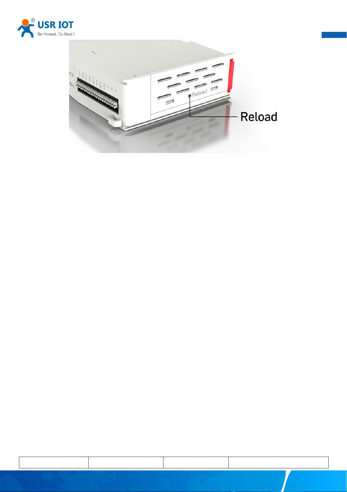
Users maybe forget the parameters they have changed during the using. In this case, using the “Reload” button can
restore the module to its factory default settings.
The “Reload” button is in the upside of the module. In the power-on state, pressing the “Reload” button and keeping
the button pressed for 3~15 seconds, the module will be reset to factory settings.
Page 9
User Manual
Your TrustWorthy Industrial IoT Partner www.pusr.com
8
5. Contact Us
Jinan USR IOT Technology Limited
Address : Floor 12 and 13, CEIBS Alumni Industrial Building, No. 3 Road of Maolingshan, Lixia District, Jinan, Shandong,
China
Official website:https://www.pusr.com
Official shop:https://shop.usriot.com
Technical support: http://h.usriot.com/
Email : [email protected]
Tel : +86-531-88826739
Fax : +86-531-88826739-808
6. Disclaimer
The information in this document provided in connection with Jinan USR IoT technology ltd. and/or its affiliates’ products.
No license, express or implied, by estoppel or otherwise, to any intellectual property right is granted by this document or in
connection with the sale of USR IoT products. EXCEPT AS SET FORTH IN THE TERMS AND CONDITIONS AS SPECIFIED IN THE
LICENSE AGREEMENT FOR THIS PRODUCT, USR IoT AND/OR ITS AFFILIATES ASSUME NO LIABILITY WHATSOEVER AND DISCLAIMS
ANY EXPRESS, IMPLIED OR STATUTORY WARRANTY RELATING TO ITS PRODUCTS INCLUDING, BUT NOT LIMITED TO, THE IMPLIED
WARRANTY OF MERCHANTABILITY, FITNESS FOR A PARTICULAR PURPOSE, OR NON‐INFRINGEMENT. IN NO EVENT SHALL USR IoT
AND/OR ITS AFFILIATES BE LIABLE FOR ANY DIRECT, INDIRECT, CONSEQUENTIAL, PUNITIVE, SPECIAL OR INCIDENTAL DAMAGES
(INCLUDING, WITHOUT LIMITATION, DAMAGES FOR LOSS OF PROFITS, BUSINESS INTERRUPTION OR LOSS OF INFORMATION)
ARISING OUT OF THE USE OR INABILITY TO USE THIS DOCUMENT, EVEN IF USR IoT AND/OR ITS AFFILIATES HAVE BEEN ADVISED
OF THE POSSIBILITY OF SUCH DAMAGES. USR IoT and/or its affiliates make no representations or warranties with respect to the
accuracy or completeness of the contents of this document and reserves the right to make changes to specifications and
product descriptions at any time without notice. USR IoT and/or its affiliates do not make any commitment to update the
information contained in this document.
7. Revision History
Version
Date
Author
Description
Page 10

User Manual
Your TrustWorthy Industrial IoT Partner www.pusr.com
9
1.0.0
2023.5.15
May, Liu
Initial
 Loading...