

Page 1
Technical Support:
1
USR-G809 User Manual
Document version: V1.0.1
h.usriot.com
Page 2

USR-G809 User Manual Technical Support:
Jinan USR IOT Technology Limited www.pusr.com
2
h.usriot.com
USR-G809 User Manual............................................................................................................................................................. 1
1. Introduction............................................................................................................................................................................. 4
1.1. Overview........................................................................................................................................................................ 4
1.2. Features.......................................................................................................................................................................... 4
1.3. Specification...................................................................................................................................................................5
1.4. Interface..........................................................................................................................................................................6
1.5. Indicator......................................................................................................................................................................... 7
1.6. Dimensions.....................................................................................................................................................................8
2. General Function..................................................................................................................................................................... 9
2.1. Web Interface............................................................................................................................................................... 10
2.2. Hostname......................................................................................................................................................................11
2.3. User Password Settings................................................................................................................................................ 11
2.4. Reboot Timer............................................................................................................................................................... 12
2.5. Backup/Upgrade...........................................................................................................................................................13
2.6. Reboot.......................................................................................................................................................................... 14
2.7. Reload Button.............................................................................................................................................................. 14
3. Interface..................................................................................................................................................................................15
3.1. WAN Interface............................................................................................................................................................. 16
3.2. LAN Interface.............................................................................................................................................................. 17
3.3. Cellular Network Interface...........................................................................................................................................18
3.4. WLAN Interface...........................................................................................................................................................20
3.5. VLAN...........................................................................................................................................................................23
3.6. DIDO............................................................................................................................................................................24
3.7. User-defined Indicator................................................................................................................................................. 27
4. Network.................................................................................................................................................................................. 28
4.1. Network Switch............................................................................................................................................................28
4.2. DHCP........................................................................................................................................................................... 29
4.3. Hostnames.................................................................................................................................................................... 29
4.4. Static Routes................................................................................................................................................................ 30
4.5. Diagnostics................................................................................................................................................................... 32
5. VPN.........................................................................................................................................................................................33
5.1. PPTP Client..................................................................................................................................................................33
5.2. L2TP Client..................................................................................................................................................................35
5.3. IPSec............................................................................................................................................................................ 36
5.4. OpenVPN..................................................................................................................................................................... 37
5.5. GRE..............................................................................................................................................................................39
6. Firewall................................................................................................................................................................................... 40
6.1. General Settings........................................................................................................................................................... 40
6.2. NAT............................................................................................................................................................................. 40
6.3. Traffic Rules.................................................................................................................................................................43
6.4. Access Restriction........................................................................................................................................................50
7. Serial Port...............................................................................................................................................................................52
7.1. Connecting Hardware...................................................................................................................................................52
Page 3

USR-G809 User Manual Technical Support:
Jinan USR IOT Technology Limited www.pusr.com
3
h.usriot.com
7.2. Serial Port Settings....................................................................................................................................................... 53
7.3. Operation Mode........................................................................................................................................................... 54
7.4. General Function..........................................................................................................................................................59
8. USR Cloud..............................................................................................................................................................................65
8.1. Cloud Monitor..............................................................................................................................................................65
8.2. Add device................................................................................................................................................................... 66
8.3. Network Status............................................................................................................................................................. 66
8.4. Parameter Configuration.............................................................................................................................................. 67
8.5. Firmware Upgrade....................................................................................................................................................... 68
8.6. Records of device......................................................................................................................................................... 69
8.7. Alarm............................................................................................................................................................................71
8.8. Remote Configuration..................................................................................................................................................73
9. Services................................................................................................................................................................................... 76
9.1. Syslog........................................................................................................................................................................... 76
9.2. NTP.............................................................................................................................................................................. 77
9.3. Email............................................................................................................................................................................ 78
9.4. SMS..............................................................................................................................................................................80
9.5. Alert..............................................................................................................................................................................80
9.6. Alert Examples.............................................................................................................................................................82
9.7. Call Reboot.................................................................................................................................................................. 92
9.8. Geolocation.................................................................................................................................................................. 92
9.9. DDNS........................................................................................................................................................................... 94
10. AT Commands Settings...................................................................................................................................................... 97
10.1. AT Command Mode.................................................................................................................................................. 97
10.2. Serial AT Commands................................................................................................................................................. 98
10.3. Network AT Commands............................................................................................................................................ 99
10.4. SMS AT Commands................................................................................................................................................ 100
Page 4

USR-G809 User Manual Technical Support:
Jinan USR IOT Technology Limited www.pusr.com
4
h.usriot.com
1. Introduction
1.1. Overview
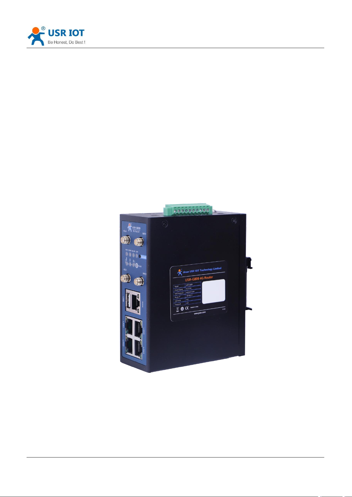
USR-G809 is a new generation of 4G LTE industrial router with rich interfaces and comprehensive functions.
It supports WIFI access point, serial to network, VLAN, DIDO, Email/SMS alert, USR Cloud service function.
G809 device adopts industrial design, with multiple hardware protection, built-in watchdog.
It has been widely used in the M2M industry in the Internet of Things, providing stable and reliable LTE
network for smart factories, photovoltaic industry, wind power generation, airport transportation, smart
medical care and other fields.
1.2. Features
Stable and Reliable
Industrial design, metal housing, protection class IP30.
Wide voltage DC 9-36V input, with reverse polarity protection
9-36V wide power supply range, anti-reverse protection.
ESD, surge and EFT protection.
Hardware watchdog, link detection mechanism make it self-recovery from unexpected failure and
guarantee system stability.
Flexible Networking
Provide 4G network, compatible with 3G/2G network.
Supports automatic network inspection, 4G/3G/2G network switching, APN/VPDN card.
Supports wired /4G multi-network online at the same time, multi-network backup function.
Supports 2.4GHz, 5GHz (Optional)WIFI.
Supports VPN (PPTP, L2TP, IPSEC, OpenVPN, GRE) and VPN encryption.
Powerful Functions
Supports multiple WAN connections, including static IP, DHCP, PPPoE, 2G/3G/4G.
Supports DDNS, static route, firewall, NAT and access restriction.
Supports RS232/RS485 serial port and multiple socket connections.
Supports VLAN function, different LAN port can be assigned different network segment.
Supports downloading/uploading the configuration files to achieve batch parameter settings.
Supports monitoring and upgrading via PUSR Cloud to achieve the remote maintenance.
Supports NTP function and restore via the “Reload” button.
Provides link detection mechanism, anti-drop mechanism to ensure that data terminals are always
online.
Supports email, SMS and DO alert function, to get the device status via the alarm information.
Supports DIDO function, simple hardware connection and flexible configuration.
Supports upgrading via USB port and custom indicator light.
Supports call reboot to achieve restart the device via the mobile phone.
Supports remote configuration via USR Cloud.
GPS positioning supported(Optional)
Page 5

Jinan USR IOT Technology Limited www.pusr.com
5
1.3. Specification
Cellular
Network
Region
EMEA/Korea/Thailand/India
Europe/Australia
Frequency
bands
LTE-FDD: B1/B3/B7/B8/B20
LTE-TDD: B38/B40/B41
WCDMA: B1/B5/B8
GSM/EDGE: B3/B8
LTE-FDD:B1/3/5/7/8/20/28
LTE-TDD:B38/40/41
WCDMA:B1/5/8
GSM/GPRS/EDGE:850/900/1800M
Hz
Theoretical
bandwidth
LTE-FDD:
Max. 150Mbps (DL)/50Mbps (UL)
LTE-TDD:
Max. 130Mbps (DL)/30Mbps (UL)
DC-HSPA+:
Max. 42Mbps (DL)/5.76Mbps (UL)
WCDMA:
Max. 384Kbps (DL)/Max.
384Kbps (UL)
EDGE:
Max. 296Kbps (DL)/Max.
236.8Kbps (UL)
GPRS:
Max. 107Kbps (DL)/Max.
85.6Kbps (UL)
LTE-FDD:
Max. 150Mbps (DL)/50Mbps (UL)
LTE-TDD:
Max. 130Mbps (DL)/30.5Mbps (UL)
DC-HSPA+:
Max. 42Mbps (DL)/5.76Mbps (UL)
WCDMA:
Max. 384Kbps (DL)/Max. 384Kbps
(UL)
EDGE:
Max. 296Kbps (DL)/Max. 236.8Kbps
(UL)
GPRS:
Max. 107Kbps (DL)/Max. 85.6Kbps
(UL)
Wireless
Parameters
Standards
IEEE802.11b/g/n, 2.4GHz, AP mode
Theoretical
bandwidth
IEEE802.11b/g, max. 54Mbps; IEEE802.11n, max. 150Mbps
Security
OPEN、WPA-PSK、WPA2-PSK
TKIP、AES
Distance
100m in open area
Serial Modem
Mode
NET, HTTPD, MODBUS
Heartbeat/R
egistry
packet
Support
Baud rate
1200/2400/4800/9600/19200/38400/57600/115200/230400
Data bits
8
Stop bits
1,2
Parity
NONE,ODD,EVEN
Serial type
RS232 or RS485
SOCKET
Socket A~D, support TCPS(Only socket A)/TCPC/UDPS/UDPC
USR-G809 User Manual Technical Support:
h.usriot.com
Page 6
USR-G809 User Manual Technical Support:
Jinan USR IOT Technology Limited www.pusr.com
6
Operating mode
Power
supply
Average
current
(mA)
Maximum
current
(mA)
Minimum
current
(mA)
LAN+WAN, full speed (4G +WLAN)
DC12V
522
811
392
LAN, full speed (4G+WLAN)
DC12V
510
801
380
LAN+WAN, full speed (WLAN)
DC12V
412
659
275
WAN, full speed (WLAN)
DC12V
366
565
246
No.
Item
Description
1
DC interface
DC:9~36V, standard 5.5*2.1mm round socket
2
WAN
1*10/100M, MDI/MDIX, 1.5KV electromagnetic isolation protection
3
LAN
4*10/100M, MDI/MDIX, 1.5KV electromagnetic isolation protection
Power
Power
supply
DC 12V/1A
Voltage
range
DC 9 ~ 36V
Operation
current
Avg. 522mA, max. 811mA/12V
Physical
characteristics
Housing
Metal, IP30 protection class
Dimensions
125.0*103.0*45.0mm (L*W*H, excluding mounting parts and antenna
base)
EMC
Level 3
Environmental
performance
Operating
temperature
-20℃~+70℃
Storage
temperature
-40℃~+125℃
Operating
humidity
5%~95%RH(non-condensing)
Storage
temperature
1%~95%RH(non-condensing)
h.usriot.com
Power consumption:
USR-G809 works at full speed, with 1 WIFI station access, 1 LAN port access, and 4G access to the external
network.
When G809 is powered by 12V and working at full speed: The average power consumption is 6.3W and the
maximum is 9.7W. The average current is 522mA and the maximum is 811mA.
Note: It is recommended to use the power adapter provided by our company.
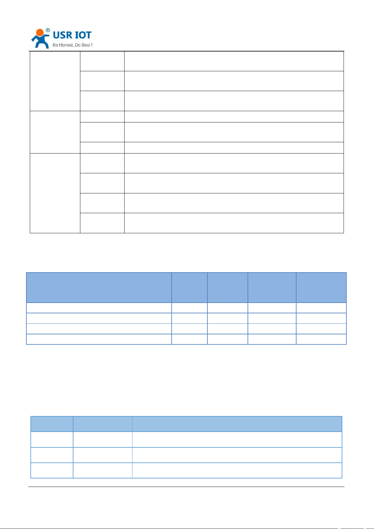
1.4. Interface
Page 7

USR-G809 User Manual Technical Support:
Jinan USR IOT Technology Limited www.pusr.com
7
4
USB interface
Firmware upgrading
5
Indicator lights
PWR、WORK、WLAN、USR、NET、SIG*3
6
SIM slot
3V/1.8V SIM card, ESD 15KV
7
Reload button
Restore to factory settings/restore the firmware/upgrade via USB port
8
WIFI antenna
interface
2* standard SMA male antenna connector
9
4G antenna
interface
2* standard SMA female antenna connector
4G-M is the main antenna, 4G-D is the auxiliary one.
10
Ground screw
Router grounding helps prevent the noise effect due to
electromagnetic interference (EMI). Connect the router to the
site ground wire by the ground screw before powering on.
11
TF card slot
Reserved interface.
12
Terminal interface
V+,V- : power interface, built-in anti-reverse protection
GNG: Ground terminal
Tx/B: RS232 or RS485, can be set via webpage
Rx/A: RS232 or RS485, can be set via webpage
DI1、DI2、DO1、DO2:DIDO terminal interface
COM: DO loop terminal.
13
TBD
Debug interface.
Item
Description
PWR
Power indicator, always on red after powered on.
WORK
Work indicator, 1 sec blink after booting.
WLAN
WiFi indicator, always on green when Wi-Fi is enabled and working properly.
USR
User-defined indicator, can be set via the webpage(socket, VPN...)
NET
Always on after connecting to the network. Two colors indicate 4G network, green
indicates 3G and red indicates 2G.
SIG(1-3)
Signal strength indicator, the more lights on, the stronger the signal.
h.usriot.com
1.5. Indicator
Page 8
Jinan USR IOT Technology Limited www.pusr.com
8
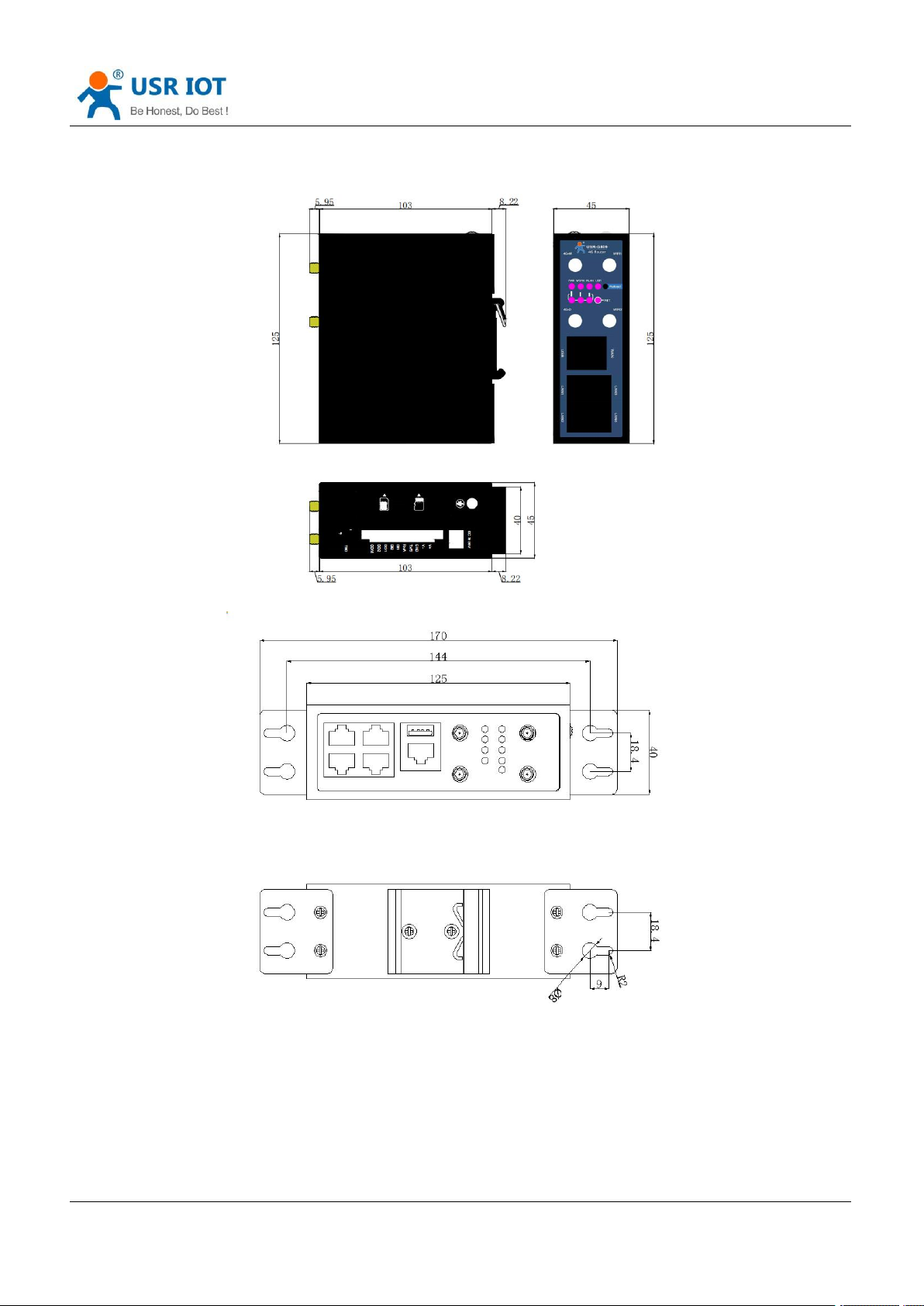
1.6. Dimensions
USR-G809 User Manual Technical Support:
h.usriot.com
Note:
Metal housing, support panel mounting and DIN-rail mounting.
Dimensions of DIN-rail mounting: 125.0*117.2*45.0mm(L*W*H, including DIN-rail parts and antenna
base).
Dimensions of panel mounting: 170.0*117.2*45.0mm(L*W*H, including DIN-rail parts, panel mounting
kits and antenna base).
Page 9
Jinan USR IOT Technology Limited www.pusr.com
9
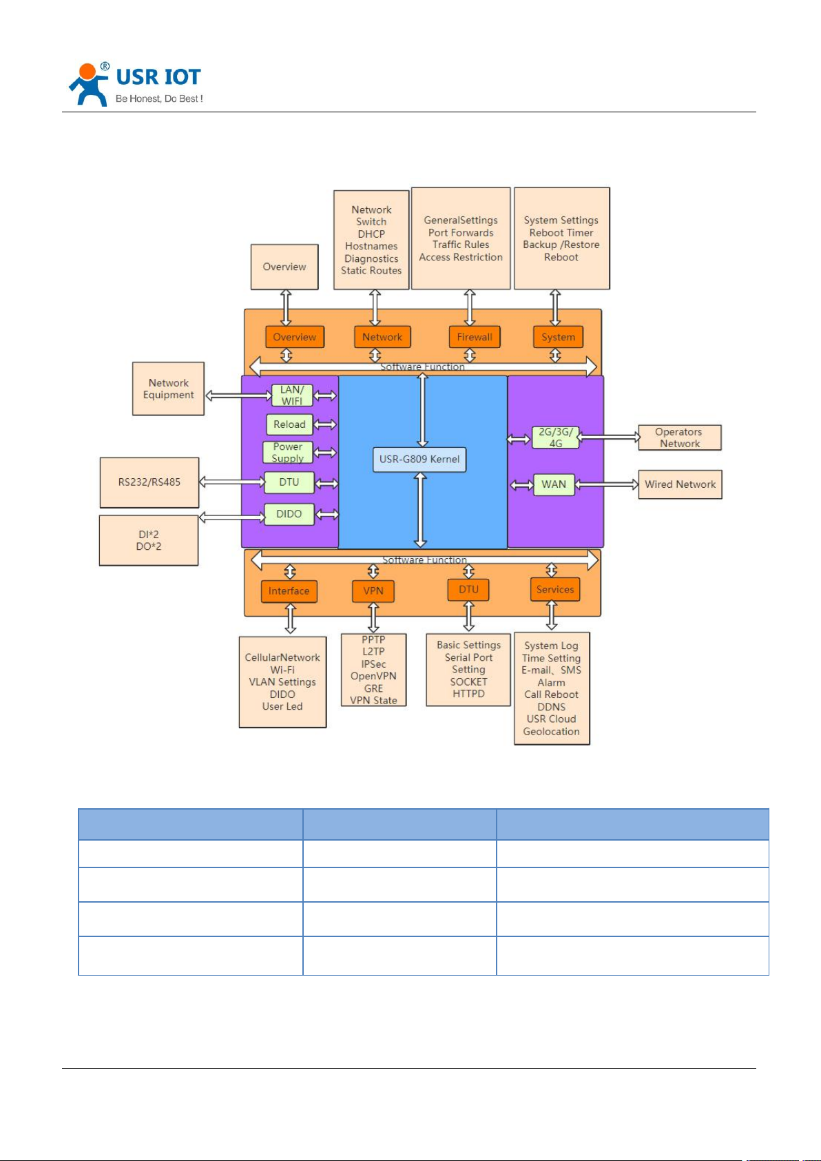
2. General Function
Network card
Code
Interface
LAN
br-lan
LAN
WIFI AP
br-lan
LAN
Wired WAN
eth0.2
WAN_WIRED
4G
eth1
WAN_4G
USR-G809 User Manual Technical Support:
h.usriot.com
Page 10
USR-G809 User Manual Technical Support:
Jinan USR IOT Technology Limited www.pusr.com
10
Parameters
Default
SSID
USR-G809-XXXX
LAN IP address
192.168.1.1
Username
root
Password
root
WiFi password
www.pusr.com
h.usriot.com
2.1. Web Interface
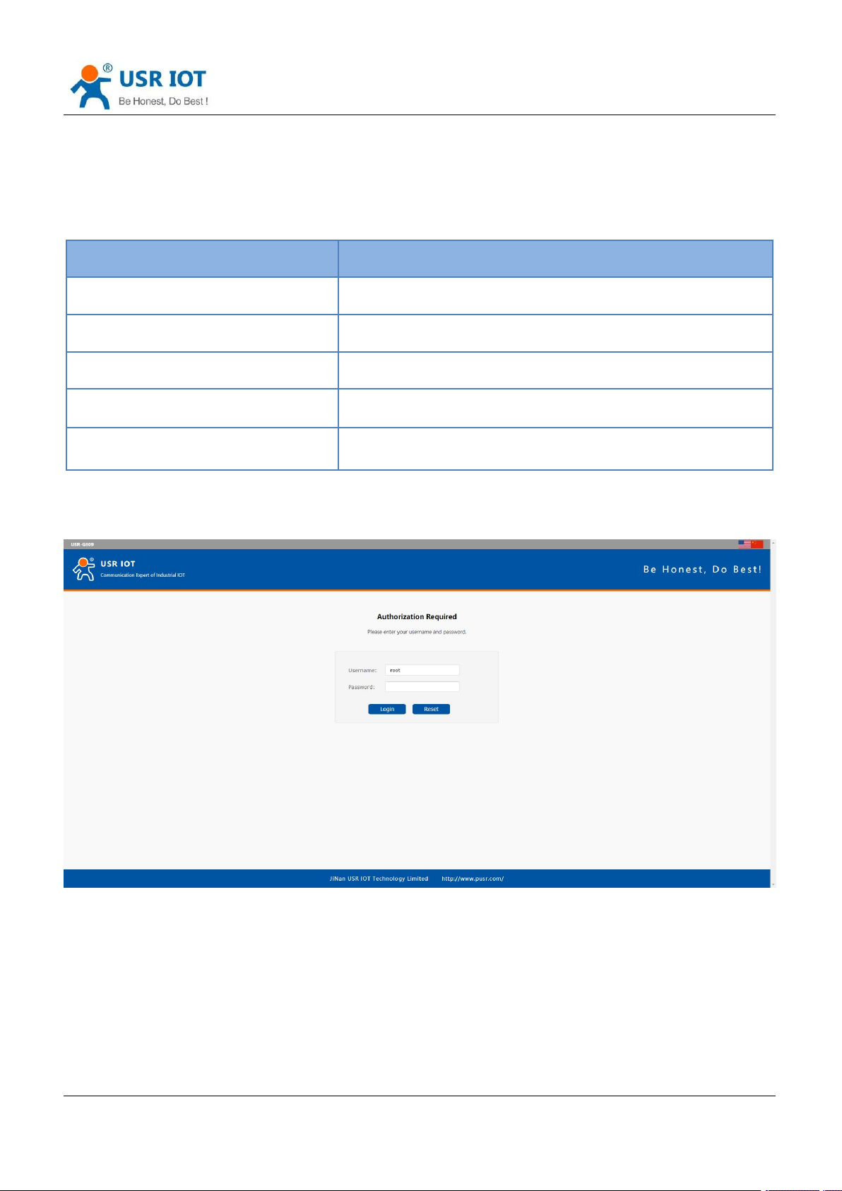
Connect PC to the LAN port of USR-G809 via a Ethernet cable, or directly connect the PC to the WiFi of the
G809. Default parameters are as below:
Enter 192.168.1.1 in the browser to log into the webpage of USR-G809, username and password are both
“root”, then click “Login”.
Page 11
Jinan USR IOT Technology Limited www.pusr.com
11
2.2. Hostname
USR-G809 User Manual Technical Support:
h.usriot.com
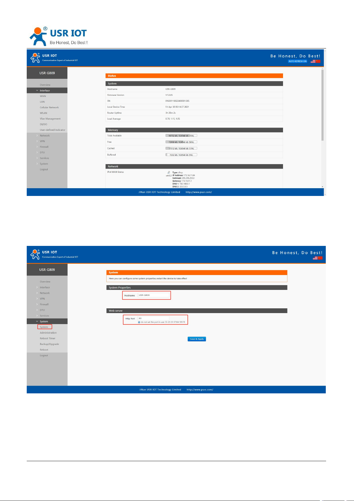
The hostname defaults to USR-G809 and the webpage port defaults to 80. After changing the parameters,
click “Save&Apply”.
2.3. User Password Settings
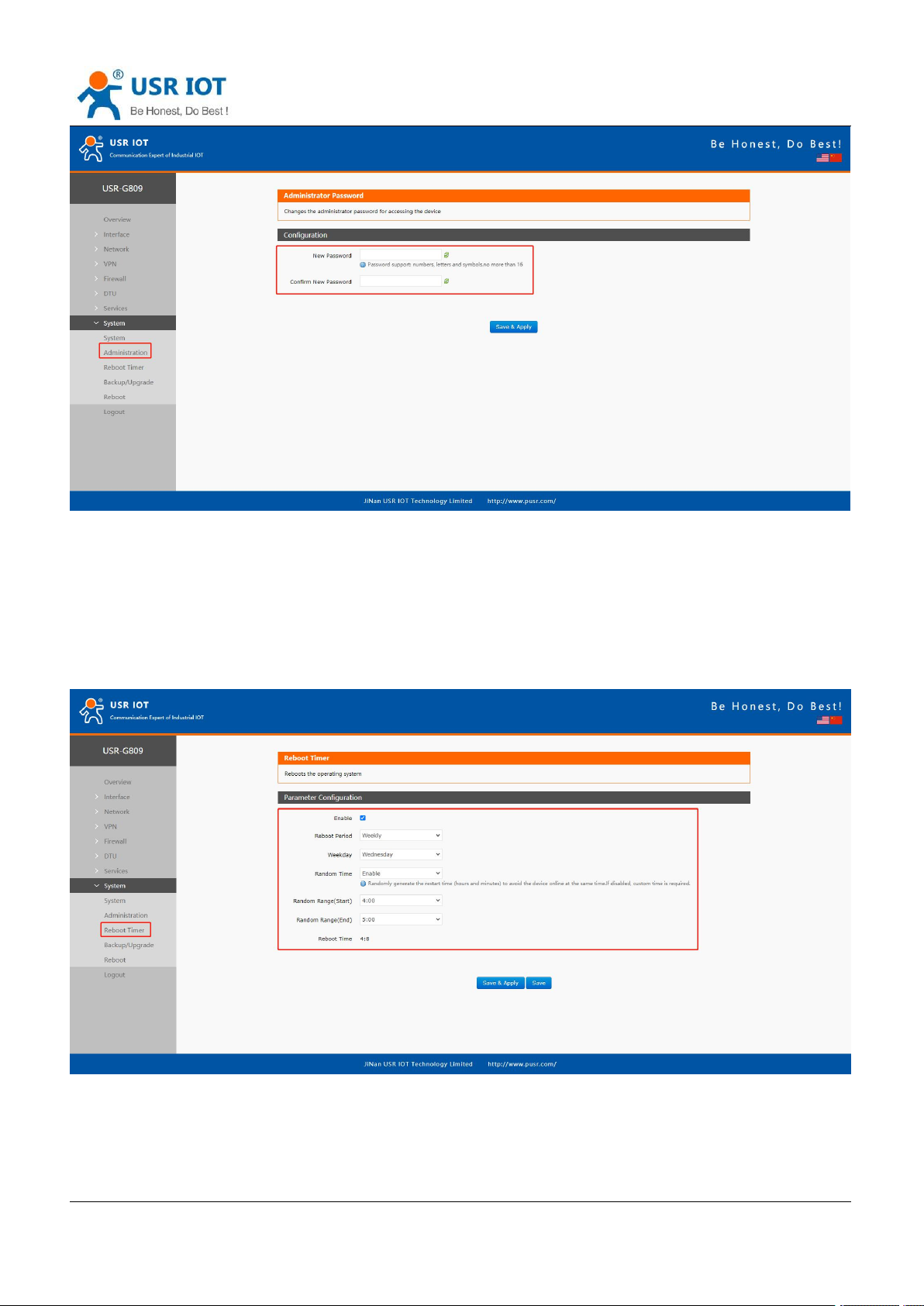
Username and password of USR-G809 default to “root”, password can be changed but the username is fixed.
This password can be used to login via Web/telnet/ssh.
Page 12
USR-G809 User Manual Technical Support:
Jinan USR IOT Technology Limited www.pusr.com
12
Note: It is recommended to change the original “root” password when login the router for the first time.
h.usriot.com
2.4. Reboot Timer
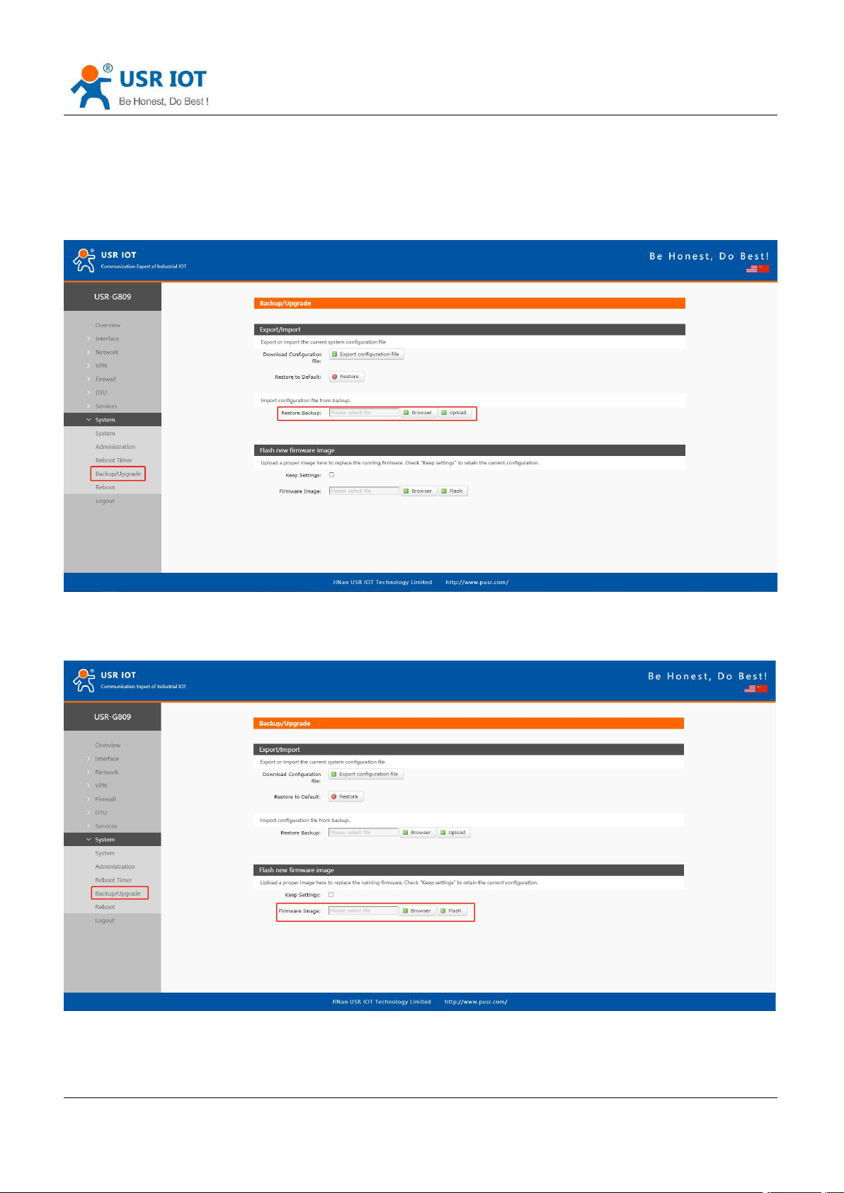
Users can restart the router at any time every day, every week and every month, and clear the running cache
regularly to improve the running stability.
Page 13
USR-G809 User Manual Technical Support:
Jinan USR IOT Technology Limited www.pusr.com
13
h.usriot.com
2.5. Backup/Upgrade
In this interface, click “Export configuration file” to download the current parameter settings to a zip file, like
backup-USR-G809-2020-08-09.tar.gz. Save and select this file, upload it to other devices to achieve batch
configuration.
USR-G809 supports upgrading firmware via webpage, after selecting the bin file, click “Flash”. It will last
about 3 minutes, please do not power off or disconnect the Ethernet cable during the upgrading. G809
defaults to upgrade without keeping the settings.
Users can also restore the device to factory settings via the “Restore” option.
Page 14
USR-G809 User Manual Technical Support:
Jinan USR IOT Technology Limited www.pusr.com
14
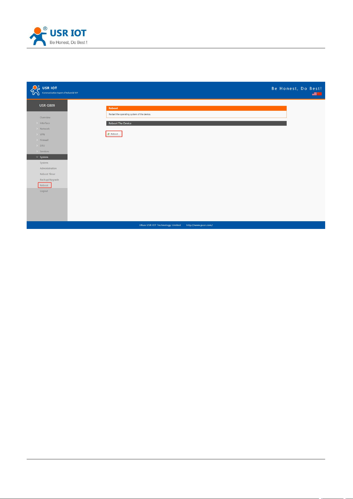
2.6. Reboot
Click “Reboot” to restart the router, same as power off. Restarting takes about 90s.
h.usriot.com
2.7. Reload Button
There is a “Reload” button in the device. Users can restore the device to factory settings, restore the firmware
and upgrade firmware via this button.
2.7.1.Hardware Reset
Users can restore the device to factory settings via below steps:
1. Power on the device. PWR will be always on and the WORK indicator will flash every 1 sec.
2. Press and hold the “Reload” button for 3~15s under the normal operation of the system.
3. Release the button for 1~2s, all the indicator lights will flash once means the device has been reset.
4. The WORK indicator will flash after the device restarting.
2.7.2.Restore the Firmware
This function can restore the device to the original firmware.
1. Press and hold the “Reload” button before power on the device.
2. Hold the “Reload” button and power on the device at the same time, release it when the NET indicator
flashes every 200ms.
3. Wait until all the indicator lights flash every 500ms, firmware is restoring now, please keep power on.
4. It will take about 2~3mins, firmware upgrade is completed when the WORK indicator flashes every 1s.
Page 15
USR-G809 User Manual Technical Support:
Jinan USR IOT Technology Limited www.pusr.com
15
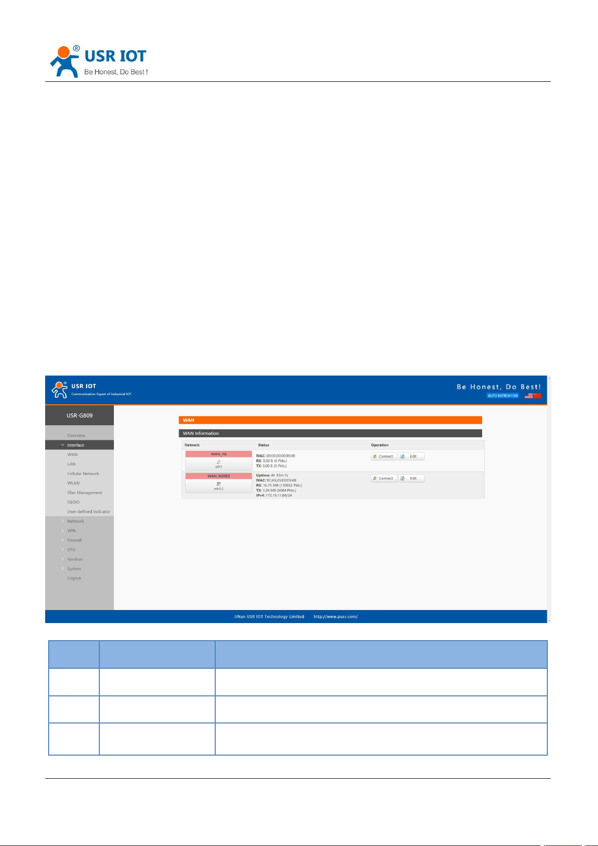
No.
Item
Description
1
Uptime
Time of this interface connected to the network.
2
MAC
MAC address of this interface.
3
RX/TX
Data received and sent of the this interface after connecting to the
network.
h.usriot.com
2.7.3.Upgrading via USB Port
USR-G809 supports upgrading via USB.
1. Place the firmware in the root directory of the U disk(FAT32 format).
2. Change the name of the firmware to “route_firmware.bin”.
3. Power off the device.
4. Insert the U disk to the USB port of the G809 device.
5. Press and hold the “Reload” button when the device is not powered on.
6. Press the “Reload” and power on the device simultaneously, release it when the NET indicator flashes
every 200ms.
7. Wait until all the indicator lights flash every 500ms, firmware is upgrading now, please keep power on.
8. Upgrading will take 2~3mins, firmware upgrade is completed when the WORK indicator flashes every 1s.
Note: The file system only supports FAT32, with up to 32GB of memory.
3. Interface
Click “Interface”, can check the network cards status, WLAN, DIDO and other information.
Page 16
Jinan USR IOT Technology Limited www.pusr.com
16
4
IPv4
Indicates this interface use the IPV4 protocol.
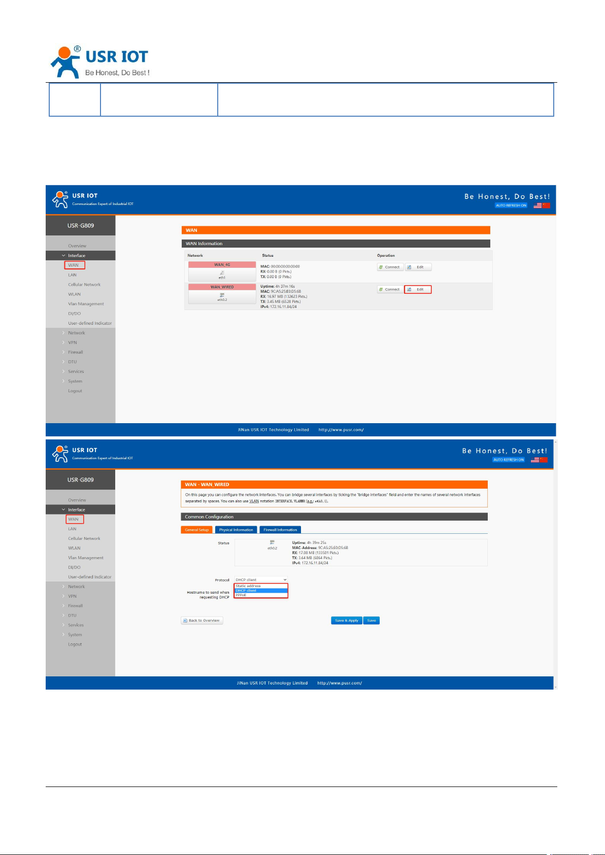
3.1. WAN Interface
USR-G809 User Manual Technical Support:
h.usriot.com
Description:
WAN interface: supports DHCP client, static IP address and PPPoE protocol. Defaults to DHCP client.
Page 17
Jinan USR IOT Technology Limited www.pusr.com
17
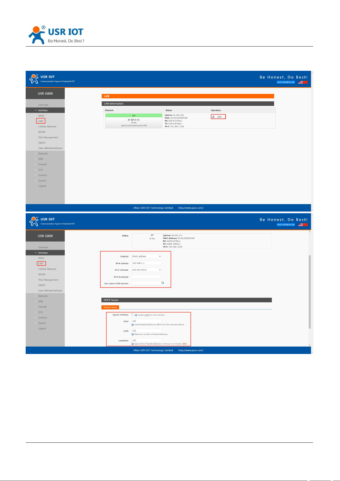
3.2. LAN Interface
USR-G809 User Manual Technical Support:
h.usriot.com
Description:
LAN interface: defaults to the IP address: 192.168.1.1, netmask 255.255.255.0.These parameters can
be modified. You need to use the new IP address to log into the webpage of the device if you have
changed it.
WiFi interface(WLAN) and wired LAN are in the same lan network.
When enable DHCP server function, all the devices connect to the LAN port of G809 will get IP
addresses automatically.
You can change the start/end address, lease time of the DHCP addresses.
The default IP address range for DHCP is 192.168.1.100 to 192.168.1.250. Default lease time is 12h.
Page 18
USR-G809 User Manual Technical Support:
Jinan USR IOT Technology Limited www.pusr.com
18
Item
Description
Default
APN
Please set the correct APN address.
Autocheck
Username
APN username
None
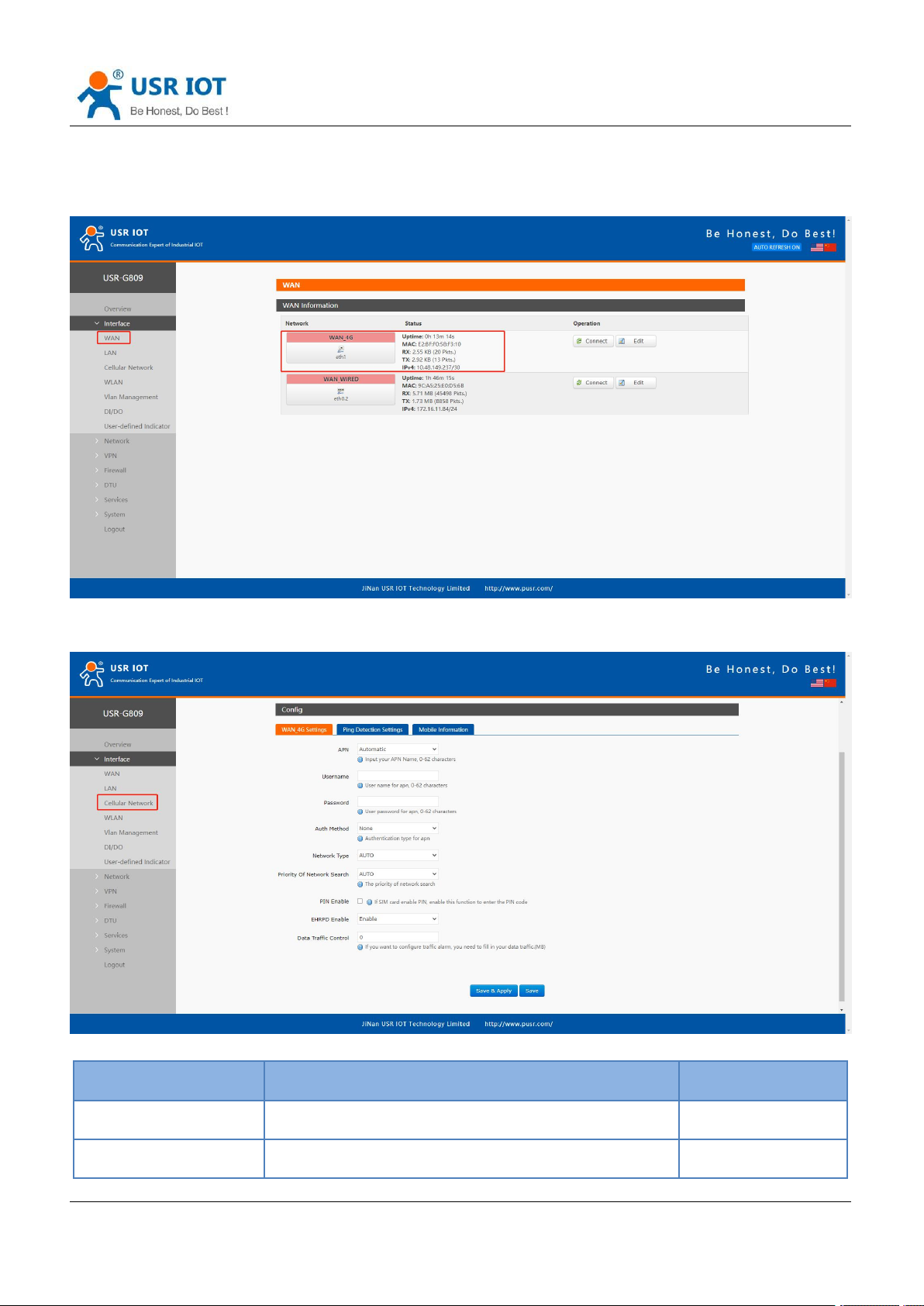
3.3. Cellular Network Interface
USR-G809 supports one 4G/3G/2G interface to access the network.
h.usriot.com
3.3.1.Cellular Network Settings
Please set the APN parameters here if the device cannot connect to the network automatically.
Page 19
USR-G809 User Manual Technical Support:
Jinan USR IOT Technology Limited www.pusr.com
19
Password
APN password
None
Auth Method
APN authentication type: None/PAP/CHAP
None
Network Type
Force 4G, 3G or 2G network
AUTO
Priority of network
search
Can set the priority of the network
AUTO
PIN Enable
Enable: Fill in the pin code of the SIM card.
Disable
EHRPD Enable
Enable/Disable
Disable
Data traffic control
0: Disable traffic alarm.
Other values: alarm when the traffic consumption
reaches this value.
0
h.usriot.com
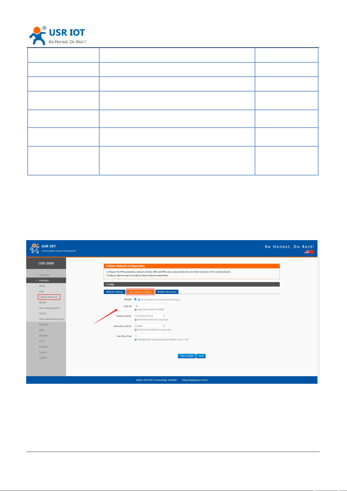
3.3.2.Ping Detection Settings
Ping detection is used to check the network status of the device, defaults to be disabled. After enable this
function, the device will try to ping the set address, dial again after reaching consecutive failures times.
It is recommended to enable the ping detection function to avoid being kicked by the base station if the device
will not transmit data for a long time.
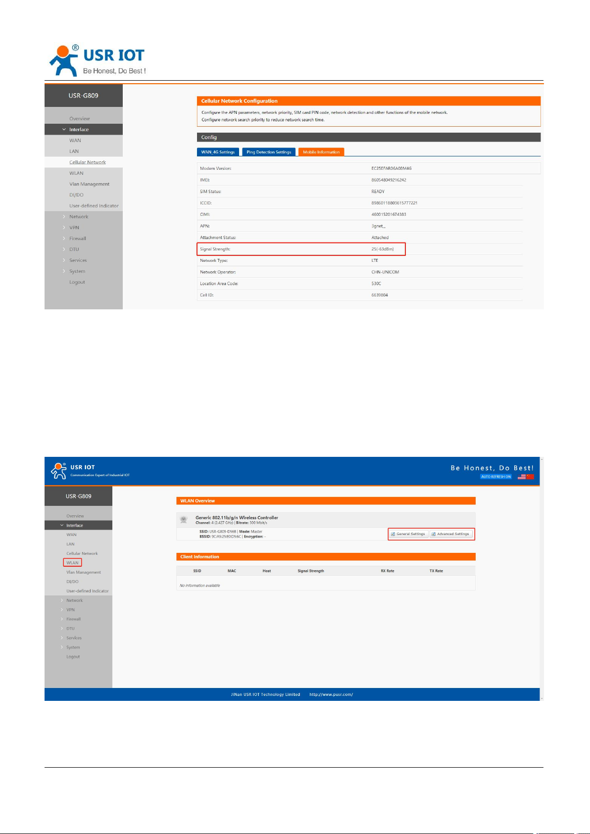
3.3.3.Mobile Information
Users can check the detailed configure information of the SIM card.
Page 20
USR-G809 User Manual Technical Support:
Jinan USR IOT Technology Limited www.pusr.com
20
Description:
Signal strength, the unit is dBm and asu. dBm=-113+2*asu.
USR-G809 supports display via dBm and asu. In 25(-63 dBm), 25 is the asu value. The range of asu is
0~31, the higher the value, the better the signal strength.
h.usriot.com
3.4. WLAN Interface
USR-G809 supports WiFi-AP function, 2.4GHz WiFi network. Users can modify the WiFi parameters in below
interface.
Description:
USR-G809 is an access point, other station devices can connect to its WiFi. It supports up to 20 WiFi
stations.
Page 21

USR-G809 User Manual Technical Support:
Jinan USR IOT Technology Limited www.pusr.com
21
Item
Description
Default
ESSID
Network name of the WiFi, can be modified.
USR-G809-8899
(8899=the last 4 bits of the
MAC)
Mode
Access Point
AP
Hide ESSID
Enable: None of client could scan the SSID. If
you want to connect to the router AP, must
enter the ESSID at WiFi client side manually.
Disable: Enable the SSID broadcasting. So that
the client can scan the SSID.
Disable
Encryption
WPA2-PSK/WPA-PSK/No Encryption
WPA2-PSK
Cipher
CCMP/TKIP/CCMP&TKIP
CCMP
Key
WiFi password, can be modified.
www.pusr.com
Radio Enable/Disable
Enable: open WiFi radio, AP can be used.
Disable: close WiFi radio, AP cannot be used,
“WLAN” indicator light will be off.
Enable
Network Mode
802.11b/g/n
802.11b/g/n
Channel
Auto, can be selected.
Auto
Bandwidth
40MHz/20MHz
40MHz
Regions
Optional
none
Channel
Optional
CH1~11
h.usriot.com
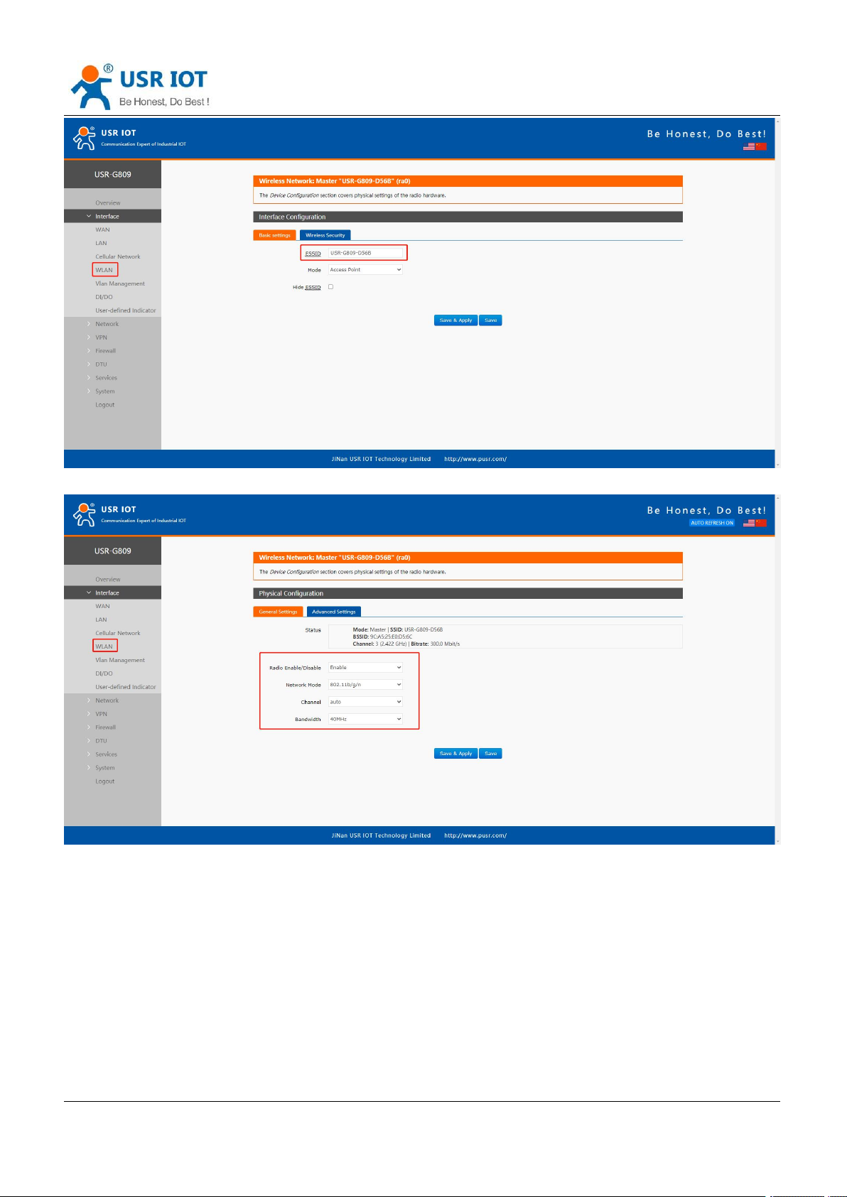
The maximum WiFi range is 100m in the open area, and within 40m in the office with obstacles.
In “WLAN---General Settings”, we can change the SSID and password.
Page 22
USR-G809 User Manual Technical Support:
Jinan USR IOT Technology Limited www.pusr.com
22
In “WLAN---Advanced Settings”, we can enable/disable the WiFi radio.
h.usriot.com
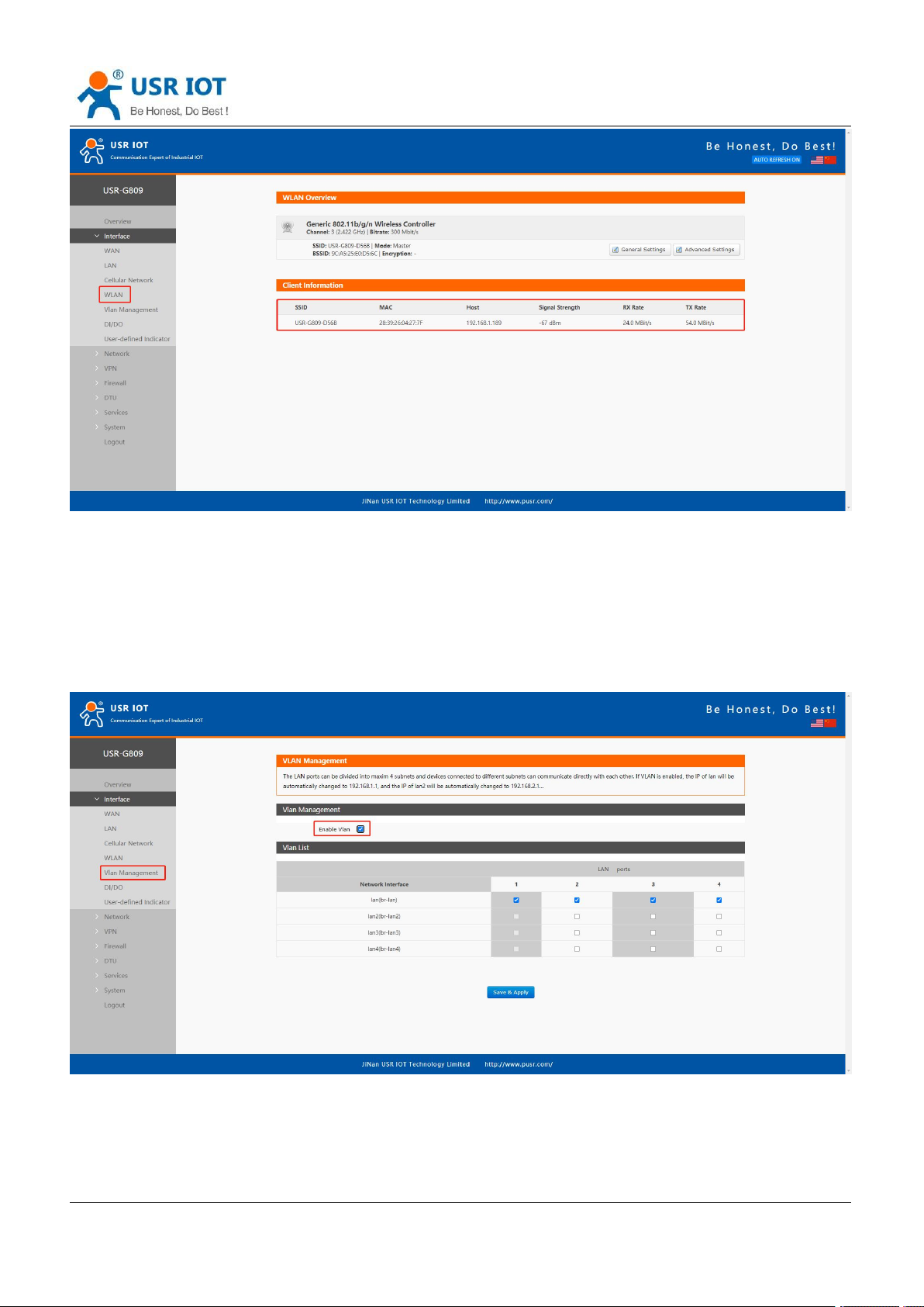
We can check the WiFi client information in below interface:
Page 23
Jinan USR IOT Technology Limited www.pusr.com
23
3.5. VLAN
USR-G809 User Manual Technical Support:
h.usriot.com
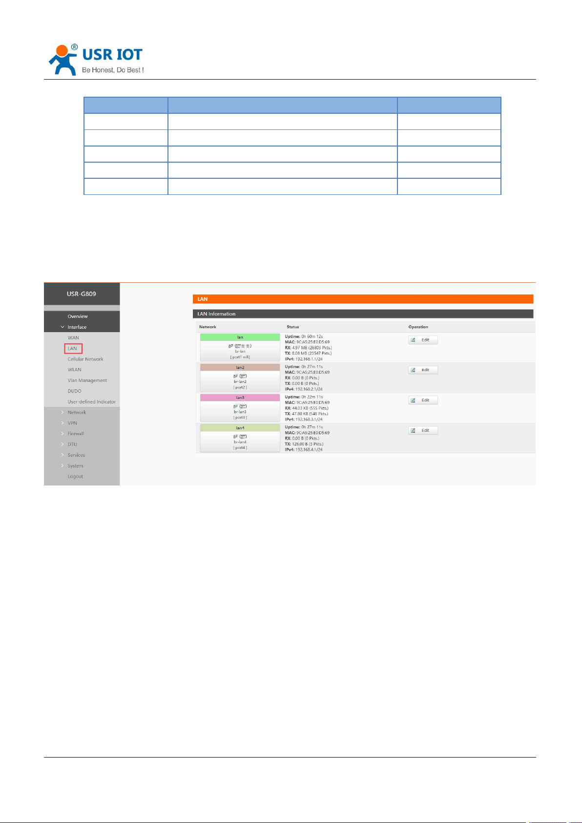
USR-G809 supports VLAN function. 4 LAN ports can be divided into multiple VLAN interfaces. If enable
VLAN function, LAN IP address will be changed to 192.168.1.1 automatically, and LAN 2 will be 192.168.2.1
and so on.
Page 24
USR-G809 User Manual Technical Support:
Jinan USR IOT Technology Limited www.pusr.com
24
Item
Description
Default
Enable VLAN
--
Disable
LAN 1 interface
Cannot modify.
lan
LAN 2 interface
Can choose between lan~lan4.
lan
LAN 3 interface
Can choose between lan~lan4.
lan
LAN 4 interface
Can choose between lan~lan4.
lan
Note:
WIFI is in lan interface, when connecting to the WIFI of G809 device, will get the IP address in the same
network segment with “br-lan”.
Users can change the network segment of VLAN in “Interface--LAN”.
h.usriot.com
3.6. DIDO
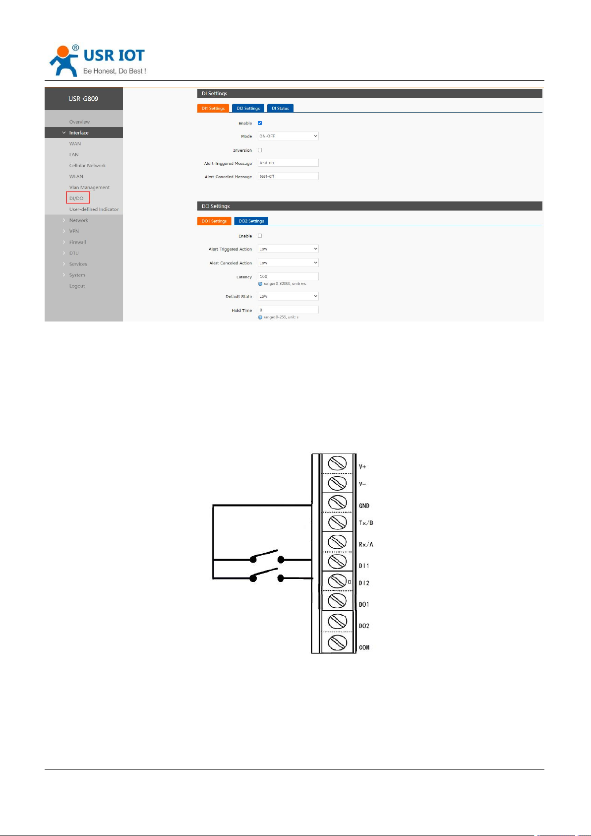
USR-G809 has DI and DO hardware interface. DI can be used to trigger the alarm, and the DO can be used
to control the device according to the trigger condition.
Page 25
USR-G809 User Manual Technical Support:
Jinan USR IOT Technology Limited www.pusr.com
25
3.6.1.Connecting Hardware
h.usriot.com
3.6.1.1. DI Hardware Connection
DI*2:Dry contact, volt-free contact, can operate as an ordinary ON/OFF switch. It is nonpolar, adaptable to
different wiring.
3.6.1.2. DO Hardware Connection
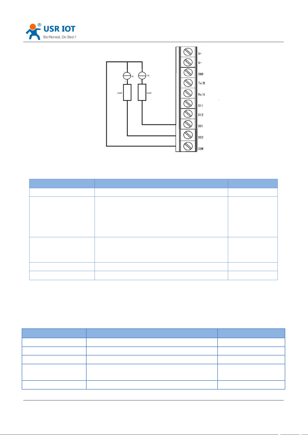
DO*2: Wet contact, active contact, can operate like a controlled switch. It is polar, and the wiring cannot be
reversed.
Page 26
USR-G809 User Manual Technical Support:
Jinan USR IOT Technology Limited www.pusr.com
26
Item
Description
Default
Enable
Check: Enable DI function
Disable
Mode
ON-OFF: DI level will trigger the alarm.
High level triggers alarm
Low level triggers alarm
Counter: DI in event counter mode.
Counting rising edges
ON-OFF
Inversion
When checking “Inversion”:
In ON-OFF mode, low level triggers alarm;
In Counter mode, counting falling edges.
Uncheck
Alert triggered message
Alert message sent after DI triggered.
None
Alert canceled message
Alert message sent after DI trigger canceled.
None
Item
Description
Default
Enable
Check: Enable DO function.
Disable
Alert triggered action
Can set to “High”, “Low”, “Pulse”.
Low
Alert canceled action
Can set to “High”, “Low”, “Pulse”.
Low
Latency (Unit: ms)
DO output alert delayed, set to 0 means output alert
immediately. (Can set to 0~30000ms)
100
Default state
Default level of DO, can be set to “High” or “Low”.
Low
3.6.2.DI Configuration
There are two DI interfaces in G809 device.
h.usriot.com
Note: When in counter mode, counting continues instead of zeroing out when the trigger value is reached.
3.6.3.DO Configuration
There are two DO interfaces in G809 device.
Page 27
USR-G809 User Manual Technical Support:
Jinan USR IOT Technology Limited www.pusr.com
27
Hold time (Unit: s)
Duration of the DO action, only valid in “High” and
“Low” of the alert triggered action. 0 means until the
next action, and other values represent the duration
of the DO action (0~255s can be set).
0
Low level width(Units: s)
Valid when the alert triggered action is “Pulse”, the
low level duration of this DO action can be set to
0~30000ms.
1000
High level width(Unit: s)
Valid when the alert triggered action is “Pulse”, the
high level duration of this DO action can be set to
0~30000ms.
1000
Alert source
DI1 or DI2 which triggers the action of this DO.
DI1
Item
Description
Default
Enable
Enable/Disable
Disable
Event
SOCKA~D、pptp、l2tp、gre、openvpn、ipsec
SOCKA
Note: The maximum voltage of DO is 36V, overcurrent protection is 300mA.
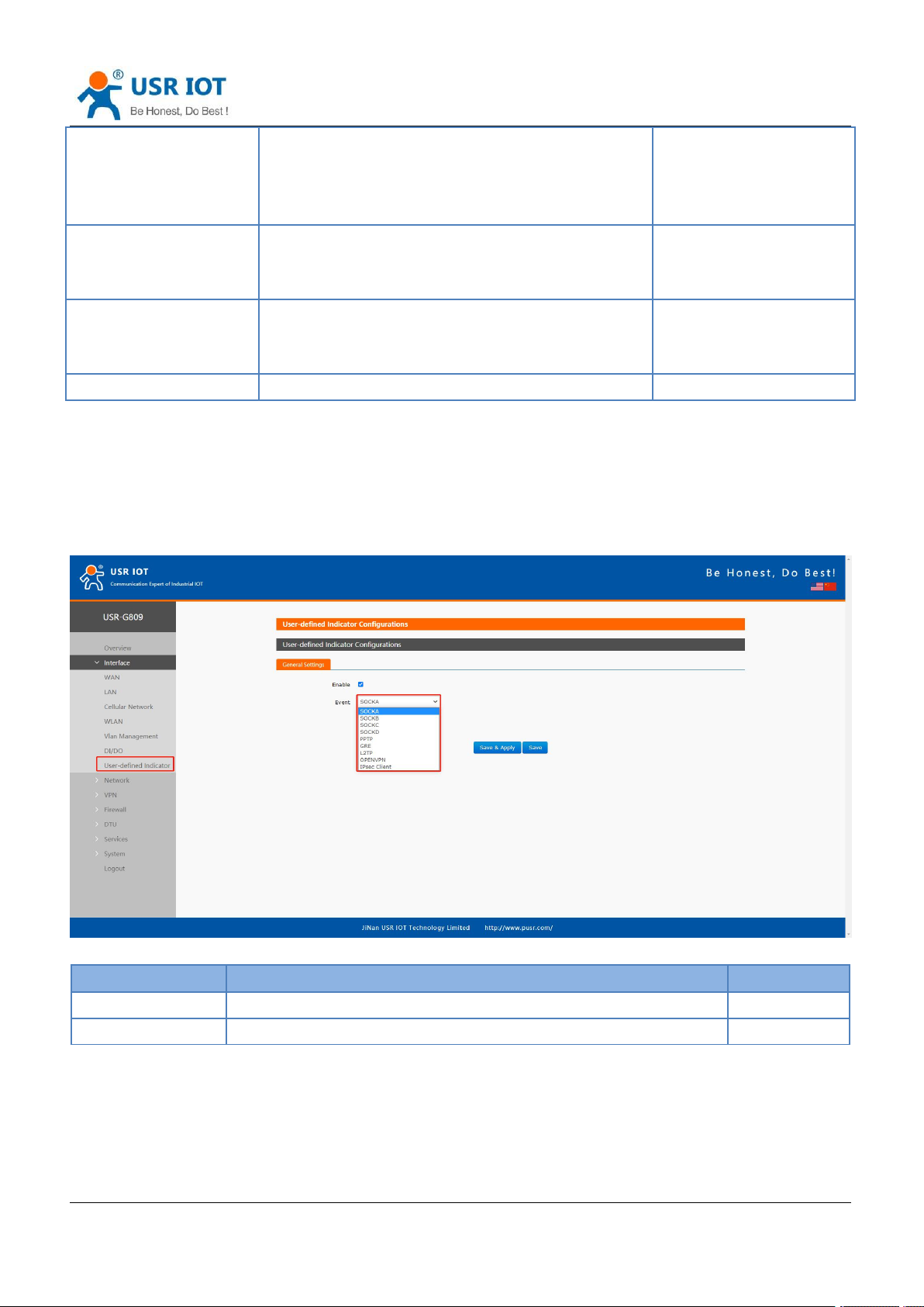
3.7. User-defined Indicator
Users can define the “USR” indicator according to the requirements.
h.usriot.com
Note:
SOCK: The light will be on when socket connection is established.
VPN: The light will be on when the VPN connection is established, only valid in Client mode(IPSEC).
TCPS: On when connecting to the clients.
TCPC/HTTPD: On when connecting to the server.
UDPC/UDPS: On when the socket connection is established.
Page 28
Jinan USR IOT Technology Limited www.pusr.com
28
4. Network
Item
Description
Default
Priority
ETH First: Select to make WAN Ethernet port as the
primary link.
4G First: Select to make SIM card as the primary wireless
link.
Disable: disable network switch function, access the
network with current link.
ETH First
Reference Mode
Custom: Router will ping the custom reference
address/domain name to check that if the current
connectivity is active.
Gateway: Router will ping the gateway to check if the
current connectivity is active.
Custom
Primary Server
IP address/domain name
114.114.114.114
Secondary Server
IP address/domain name
119.29.29.29
Thirdly Server
IP address/domain name
8.8.8.8
Ping interval (s)
Set the ping interval, 1-600s.
10
Package size(byte)
Set the ping package size, 32-1024 bytes.
100
Timeout (ms)
Ping timeout, 100-20000ms
2000
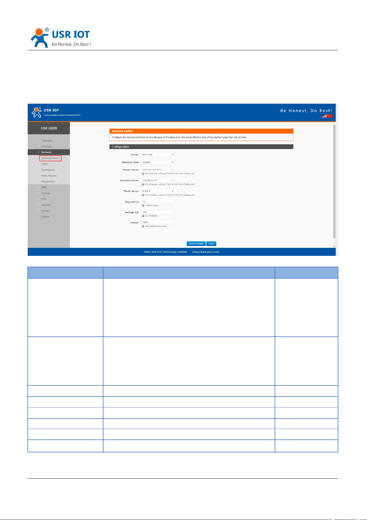
4.1. Network Switch
USR-G809 User Manual Technical Support:
h.usriot.com
Note: Router will ping the reference addresses one by one, it will not switch the network if can ping
successfully.
Page 29
USR-G809 User Manual Technical Support:
Jinan USR IOT Technology Limited www.pusr.com
29
h.usriot.com
4.2. DHCP
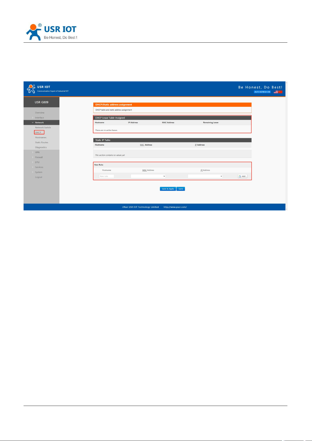
Static address assignment: In “Network -- DHCP”, we can assign a fixed IP address to a DHCP client device.
User can bind the MAC address with a fixed IP address, up to 20 binding rules can be added.
Note:
Hostname is empty means IP and MAC binding.
MAC is empty means hostname and IP binding.
To set all means to bind a MAC to an IP and set the hostname for this MAC.
IP address must be in the same network segment with the LAN IP address of USR-G809.
4.3. Hostnames
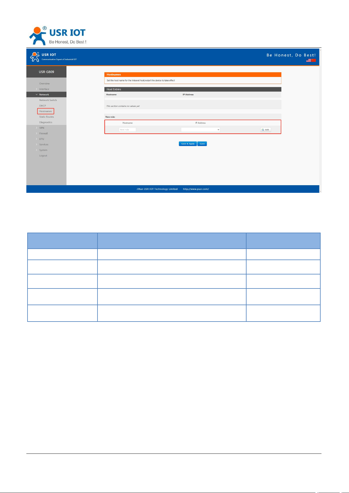
USR-G809 supports custom domain name resolution. Set the hostname and IP address in below interface, to
achieve the mapping between hostname and IP address.
The outside IP address can also be mapped(must be a unique public IP address). The hostname of DHCP
and static IP cannot be a number. After setting all parameters, restart the device to take the parameters
effect.
Page 30
Jinan USR IOT Technology Limited www.pusr.com
30
4.4. Static Routes
Item
Description
Default
Interface
Lan, wan_4G, wan_wired, vpn
lan
Target
Destination IP address or IP range
Null
Netmask
Netmask of the destination network
Null
Gateway
The IP address to forward to
Null
Metric
Used to make routing decisions
Null
USR-G809 User Manual Technical Support:
h.usriot.com
USR-G809 supports up to 20 static route rules.
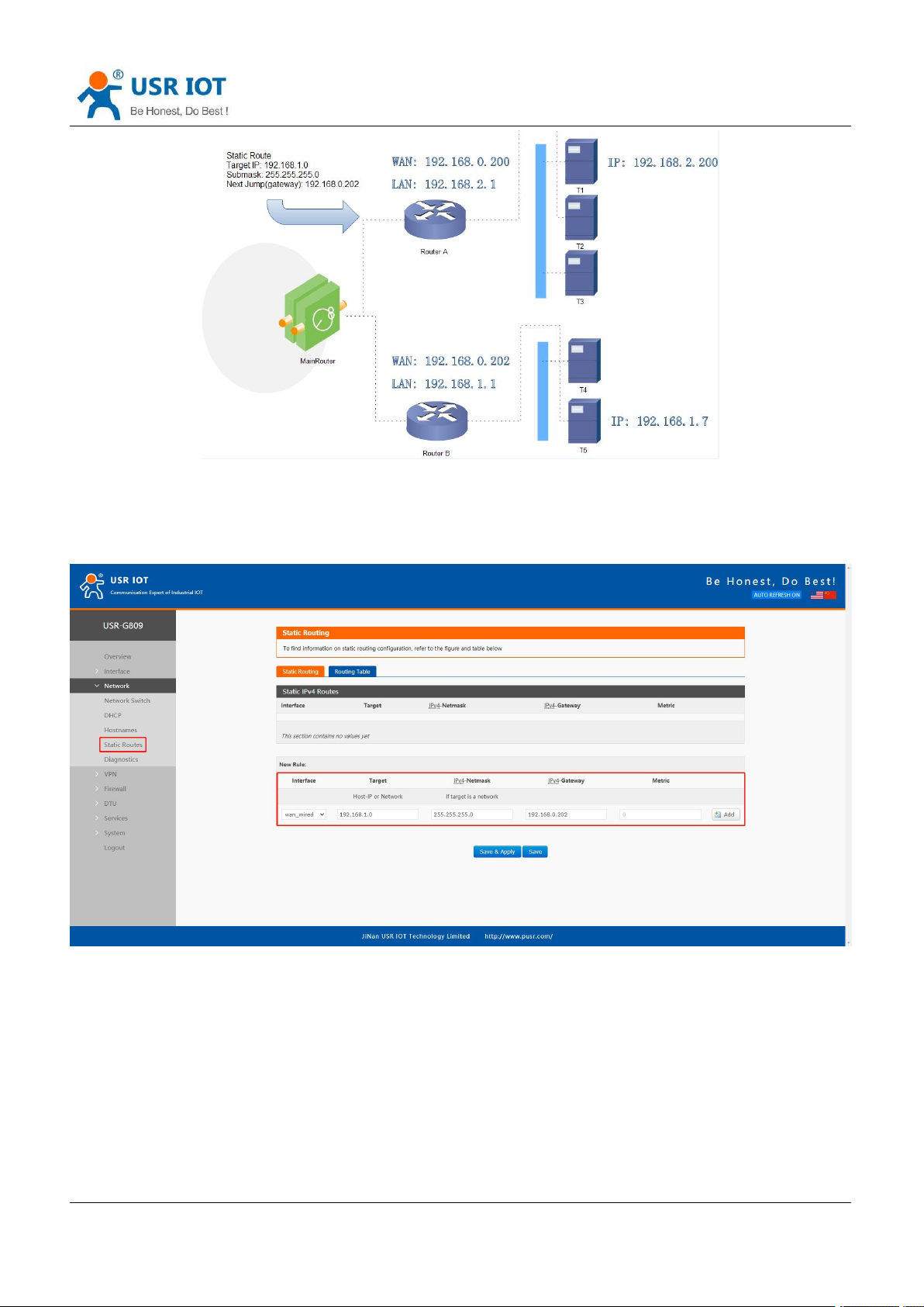
Test example:
Page 31
USR-G809 User Manual Technical Support:
Jinan USR IOT Technology Limited www.pusr.com
31
h.usriot.com
The WAN port of router A and router B are connected to the network 192.168.0.0, LAN network of router A is
192.168.2.0, LAN network of router B is 192.168.1.0.
Now we can do a static route in router A, when we access the 192.168.1.X, will automatically forward to
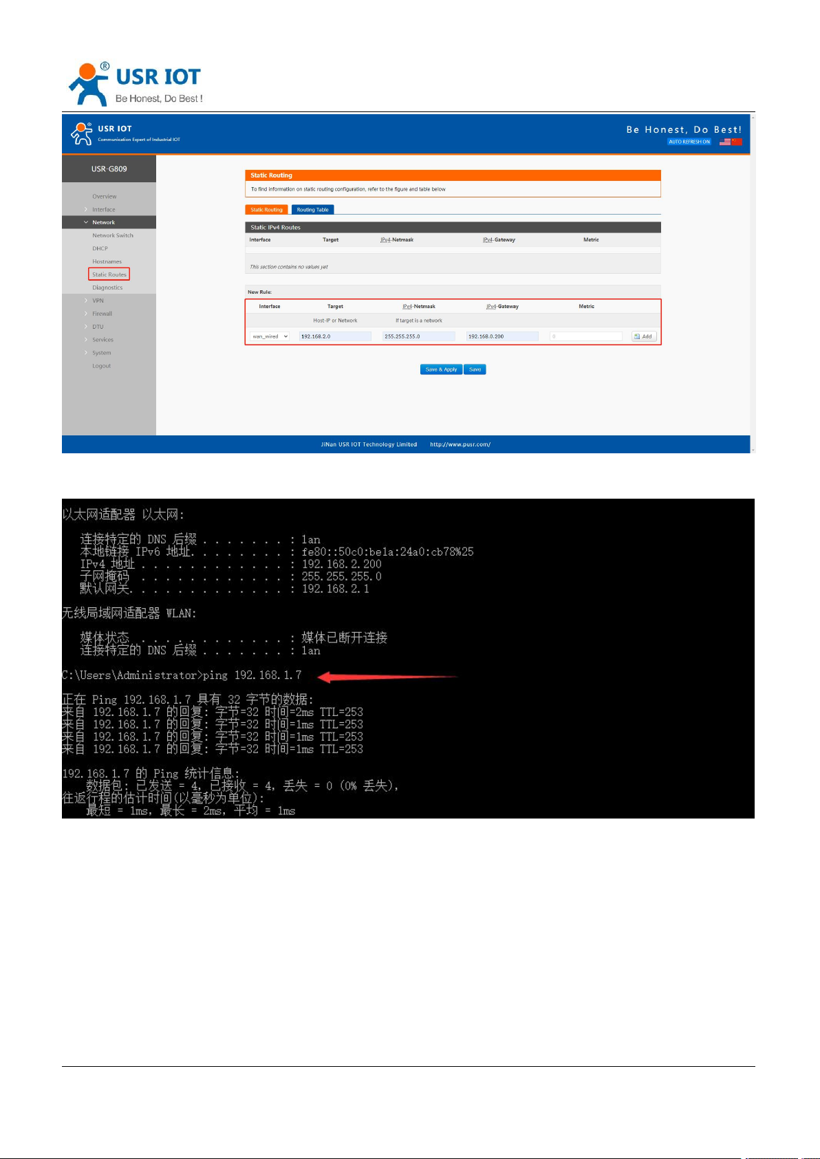
router B.
In router B:
Page 32
USR-G809 User Manual Technical Support:
Jinan USR IOT Technology Limited www.pusr.com
32
After setting all parameters, restart the device.
Ping from T1 to T5:
h.usriot.com
4.5. Diagnostics
Page 33
USR-G809 User Manual Technical Support:
Jinan USR IOT Technology Limited www.pusr.com
33
No.
Protocol
Version
1
PPTP
V1.10.0
2
L2TP
V1.3.15
3
IPSec
V5.3.3
4
OpenVPN
V2.3.18
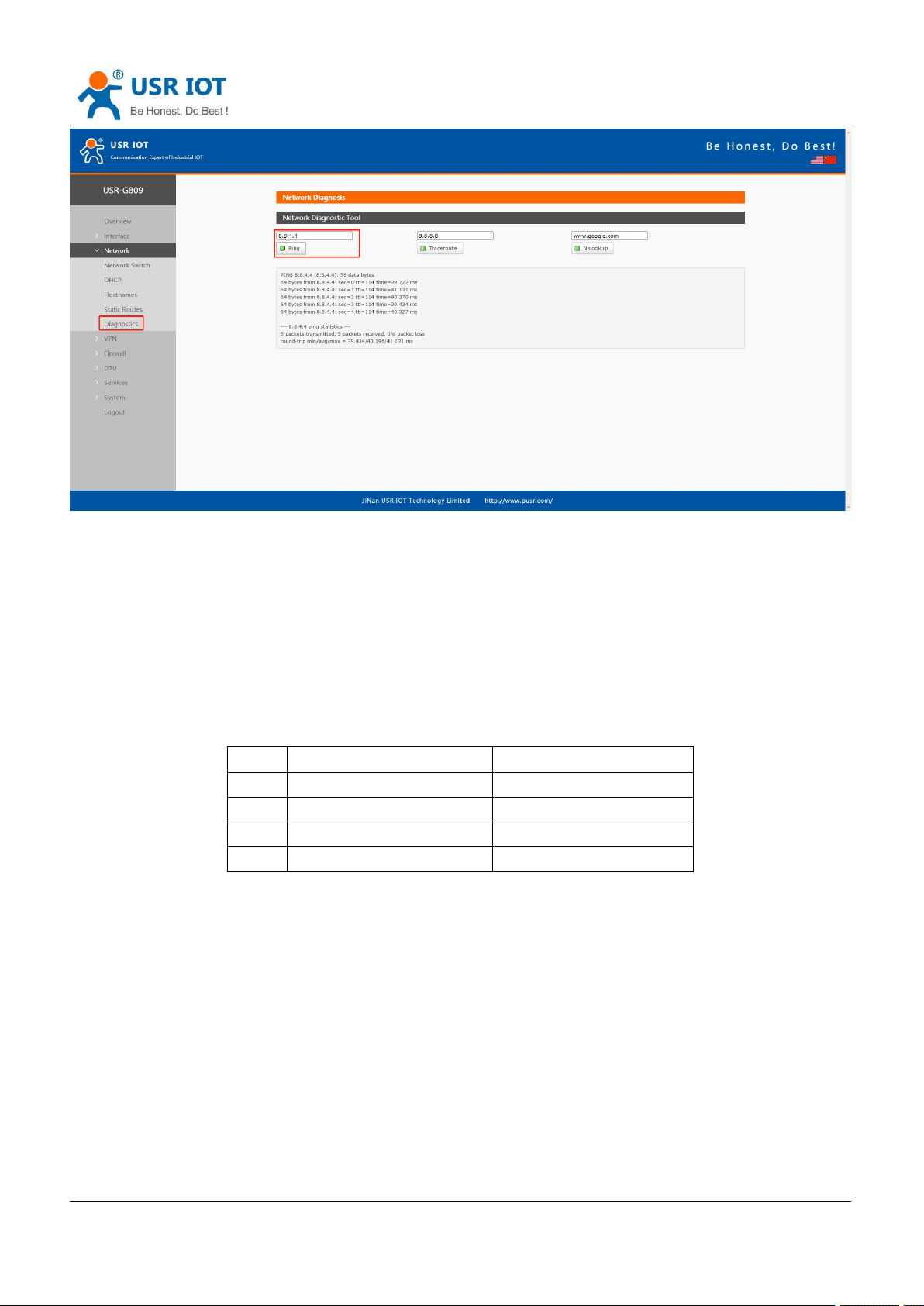
This interface provides users three tools: Ping, Traceroute and Nslookup.
Ping: Ping a destination address to check the network status.
Traceroute: Send traceroute request to a destination address.
Nslookup: Resolve the domain name to an IP address.
h.usriot.com
5. VPN
USR-G809 supports PPTP, L2TP, IPSEC, openVPN and GRE.
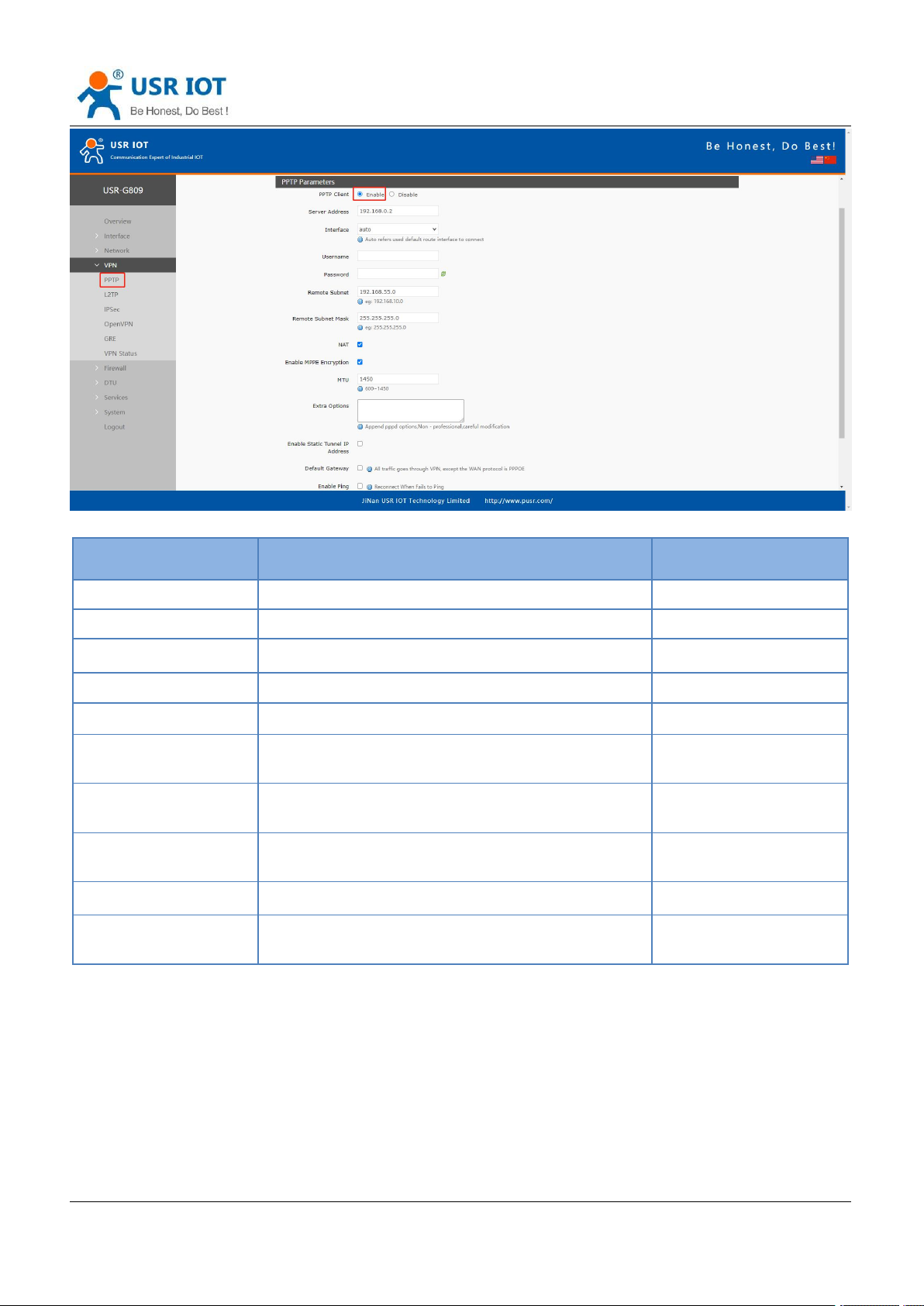
5.1. PPTP Client
This interface allows users to set the PPTP server parameters.
Page 34
USR-G809 User Manual Technical Support:
Jinan USR IOT Technology Limited www.pusr.com
34
Item
Description
Default
Server address
VPN server address or domain name
192.168.0.2
Interface
wan_4G, wan_wired or auto
auto
Username/Password
Get from the VPN server
Null
Encryption
MPPE or no encryption
MPPE
MTU
Consistent with the VPN server
1500
NAT
The source IP address of host behind G809 will be
disguised before accessing the remote address.
Enable
Remote Subnet/Mask
When NAT is enabled, can achieve the subnet
communication under VPN.
192.168.55.0/255.255.2
55.0
Enable Static Tunnel IP
Address
When it is disabled, VPN server will assign an IP
address dynamically.
Disable
Extra Options
Append pppd parameters, magic number.
Null
Enable ping
Real-time VPN online detection and reconnection
mechanism.
Disable
h.usriot.com
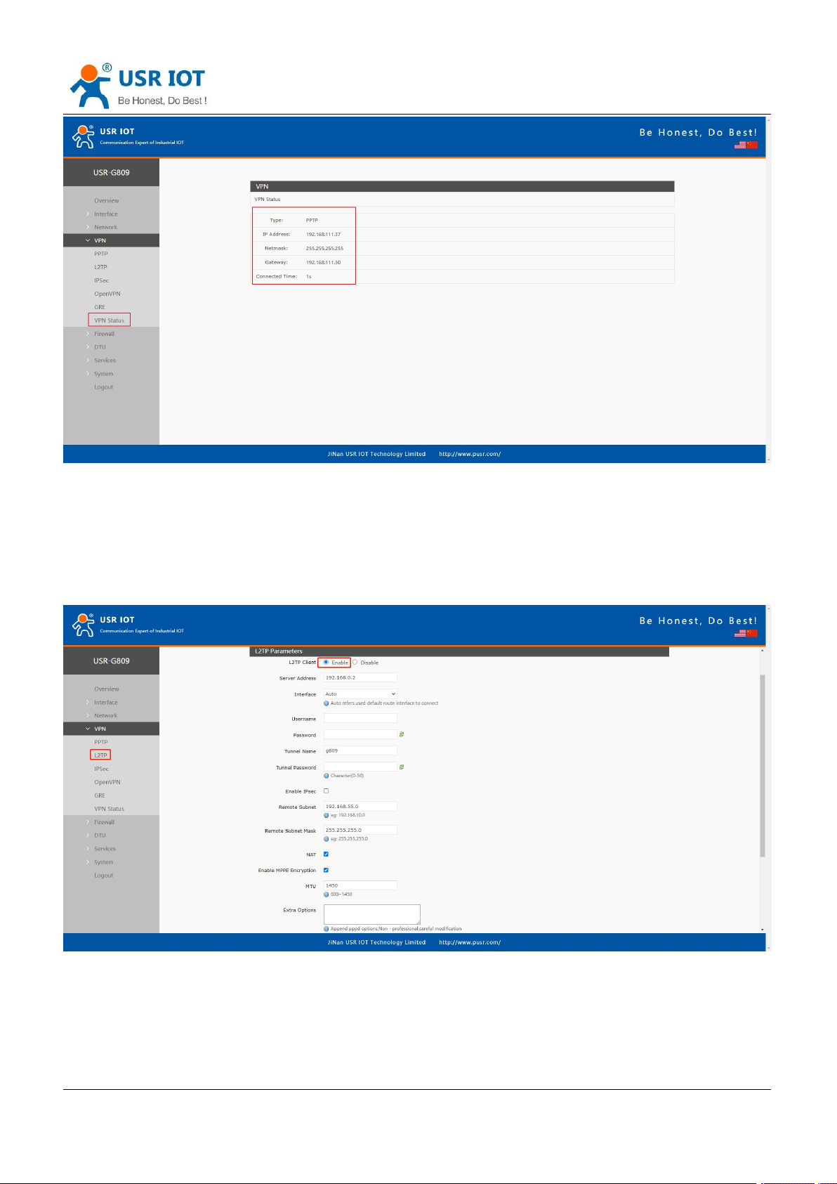
After connecting to PPTP server, we can check the connection status in “VPN Status”.
Page 35
Jinan USR IOT Technology Limited www.pusr.com
35
5.2. L2TP Client
USR-G809 User Manual Technical Support:
h.usriot.com
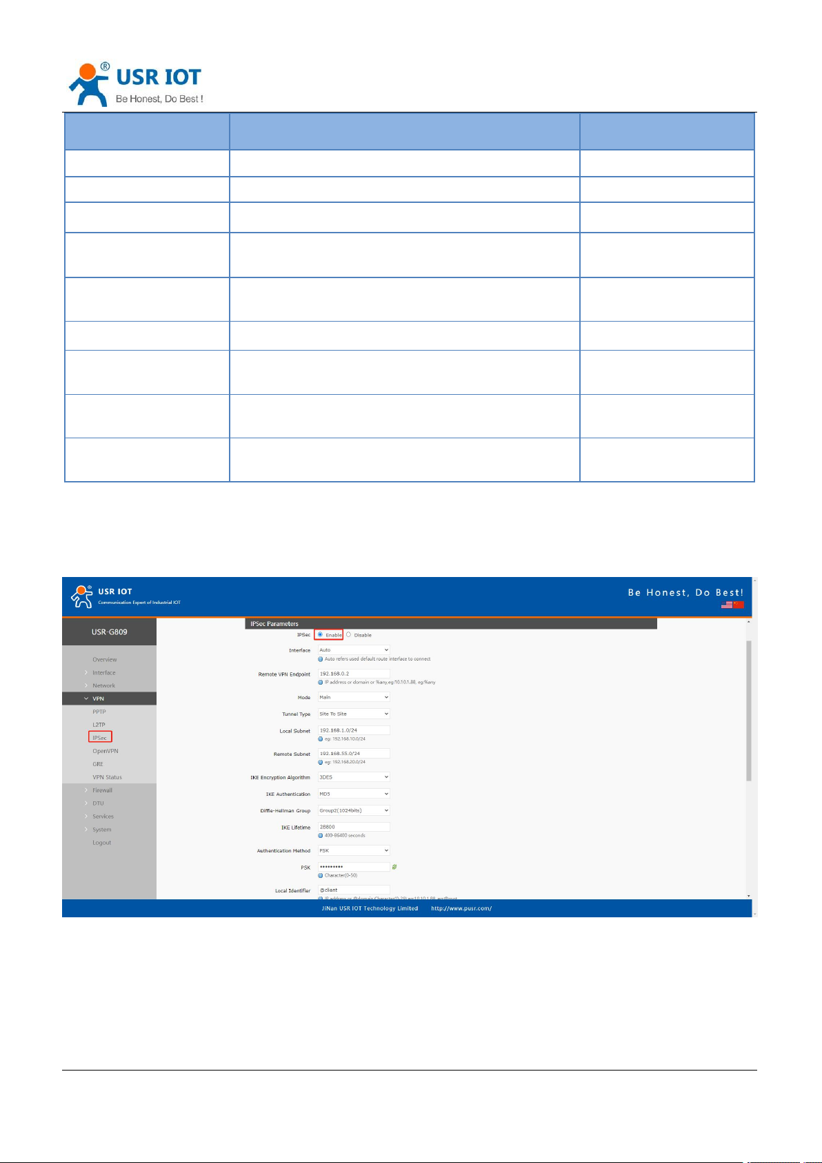
L2TP is the layer 2 tunneling protocol which similar to PPTP. G809 supports tunnel password authentication,
supports MPPE and L2TP over IPSEC encryption.
In “VPN---L2TP”, enable L2TP Client, set the related parameters.
Page 36
USR-G809 User Manual Technical Support:
Jinan USR IOT Technology Limited www.pusr.com
36
Item
Description
Default
Server address
VPN server address or domain name
192.168.0.2
Interface
wan_4G, wan_wired or auto
auto
Username/Password
Get from the VPN server
Null
Encryption/Authenticati
on
Tunnel password, MPPE, IPSEC, consistent with the
VPN server.
MPPE
Enable Static Tunnel IP
Address
When it is disabled, VPN server will assign an IP
address dynamically.
Disable
Extra Options
Append pppd parameters, magic number.
Null
NAT
The source IP address of host behind G809 will be
disguised before accessing the remote address.
Enable
Remote Subnet/Mask
When NAT is enabled, can achieve the subnet
communication under VPN.
192.168.55.0/255.255.2
55.0
Enable ping
Real-time VPN online detection and reconnection
mechanism.
Disable
After connecting to L2TP server, we can check the connection status in “VPN Status”.
h.usriot.com
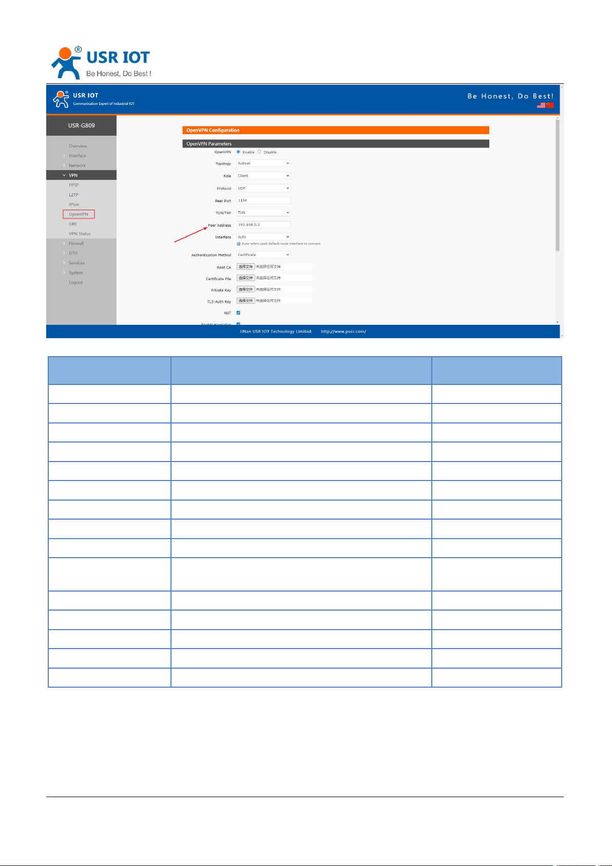
5.3. IPSec
Descriptions:
Page 37

USR-G809 User Manual Technical Support:
Jinan USR IOT Technology Limited www.pusr.com
37
Item
Description
Default
Interface
wan_4G, wan_wired or auto
auto
Remote VPN Endpoint
VPN Client/Server, remote endpoint IP/domain
192.168.0.2
Mode
Main, aggressive
main
Tunnel type
Site to site, site to host, host to host, host to site
Site to site
Local subnet
IPSec local subnet and mask
192.168.1.0/24
Remote subnet
IPSec remote subnet and mask
192.168.55.0/24
Local Identifier
IP address or FQDN preceded by @, e.g. @domain
@client
Peer Identifier
IP address or FQDN preceded by @, e.g. @domain
@server
IKE Encryption
Phase 1 IKE encryption algorithm, authentication
and DH group settings.
3DES/MD5/Group2
IKE Lifetime
Set the lifetime in IKE negotiation, 400~86400s
28800
Authentication Method
Pre-shared key
PSK
ESP encryption
3DES/AES-128/AES-192/AES-256
AES-128
ESP Authentication
SHA-1/SHA2-256/MD5
SHA-1
ESP Lifetime
Set the ESP lifetime/s
3600
PFS Group
None/DH1/DH2/DH5
DH2
DPD Interval
Set the interval after which DPD is triggered if no
IPsec protected packets is received from the peer/s
60
DPD Timeout
Set the timeout of DPD packets/s
60
DPD Action
Sets the action for connection detection,
None/Clear/Hold/Restart
Restart
h.usriot.com
After connected successfully, we can check the connection status in “VPN - VPN Status”.
5.4. OpenVPN
Page 38
USR-G809 User Manual Technical Support:
Jinan USR IOT Technology Limited www.pusr.com
38
Item
Description
Default
TUN/TAP
TUN/TAP
TUN
Protocol
TCP/UDP
UDP
Peer Port
Listening port of the OpenVPN server
1194
Peer Address
IP/domain name of the OpenVPN server
192.168.0.2
Interface
Auto/wan_wired/wan_4g
Auto
Root CA
Import the ca root file to the router
Null
Certificate File
Import the client certificate file to the router
Null
Private Key
Import the client private key to the router
Null
TLS-Auth Key
Import the TLS authentication key to the router
Null
Encrypt Algorithm
None/Blowfish-128/DES-128/3DES-192/AES-128/A
ES-192/AES-256
Blowfish-128
Hash Algorithm
None/SHA1/SHA256/SHA512/MD5
None
Enable LZO
Yes/No/Adaptive
Adaptive
Enable Keepalive
Defaults to 10,120, consistent with VPN server
On
MTU
Consistent with VPN server
1500
Enable Ping
Reconnect when fails to ping
Off
h.usriot.com
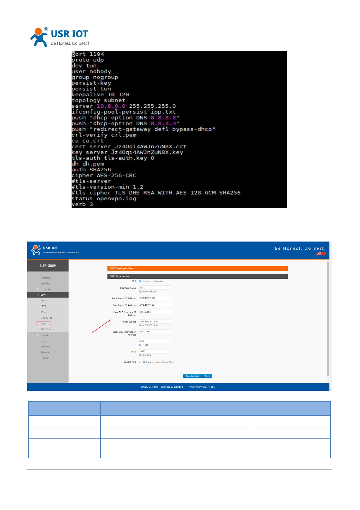
After connected successfully, we can check the connection status in “VPN - VPN Status”.
Attached: OpenVPN server configuration under Linux:
Page 39
USR-G809 User Manual Technical Support:
Jinan USR IOT Technology Limited www.pusr.com
39
Item
Description
Default
Local public IP address
Local wan_wired or wan_4g address
192.168.0.151
Peer public IP address
Remote GRE WAN IP address
192.168.0.10
Peer GRE Interface IP
Address
Remote GRE tunnel IP address
10.10.10.1
h.usriot.com
5.5. GRE
Page 40
Jinan USR IOT Technology Limited www.pusr.com
40
Peer Subnet
IP/Mask:
255.255.255.0: IP/24
255.255.255.255: IP/32
192.168.55.0/24
Local GRE Interface IP
Address
Local GRE tunnel IP address
10.10.10.2
TTL
Set the TTL parameters(1~255)
255
MTU
Set the MTU(600~1450)
1450
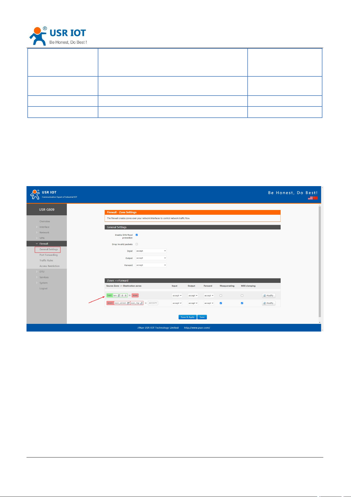
6. Firewall
6.1. General Settings
USR-G809 User Manual Technical Support:
h.usriot.com
Descriptions:
1. Input: Data packets access to the router’s IP.
2. Output: Data packets sent by the router’s IP.
3. Forward: Data forwarding between the interfaces, not go through the router.
4. Masquerading: WAN and 4G interface. The source IP address will be disguised before accessing the
external network.
5. MSS clamping: Limit the MSS packets, generally is 1460.
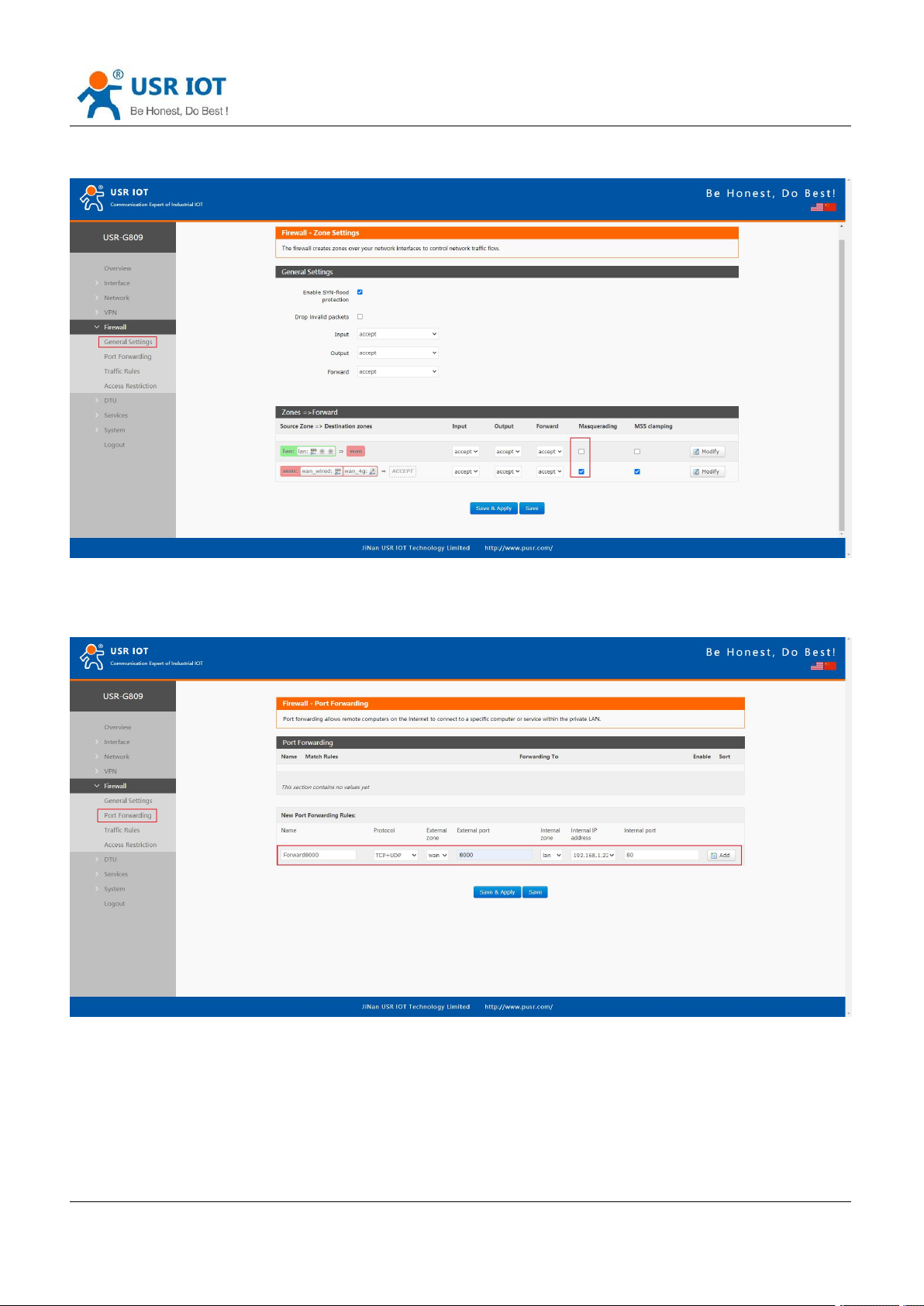
6.2. NAT
6.2.1.Masquerading
Masquerading will disguise the source IP address of the data packets to the WAN IP address of the router.
Page 41
USR-G809 User Manual Technical Support:
Jinan USR IOT Technology Limited www.pusr.com
41
h.usriot.com
The masquerading and MSS clamping of the WAN interface must be enabled, which must be disabled in the
LAN interface.
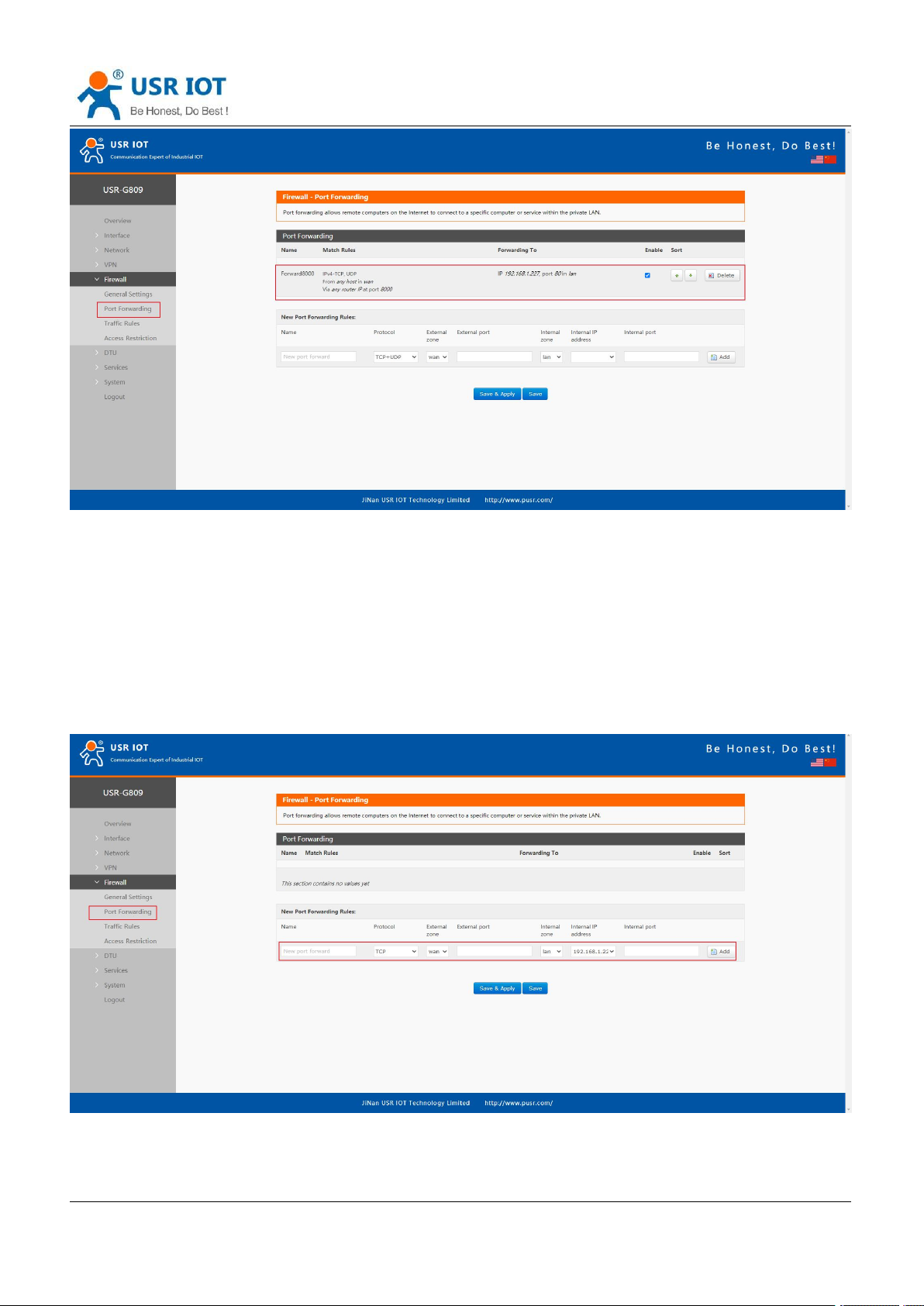
6.2.2.Port Forwarding
Port forwarding rules can map a specific port of the WAN interface to a intranet host.
Click “Save&Apply”.
Page 42
USR-G809 User Manual Technical Support:
Jinan USR IOT Technology Limited www.pusr.com
42
h.usriot.com
When we access the port 8000 of the WAN interface, it will be forwarded to 192.168.1.227, port 80.
Note: Users can also set the port number range in port forwarding interface(E.g: 8888-9999), the
external port number range must be same with the internal port number range.
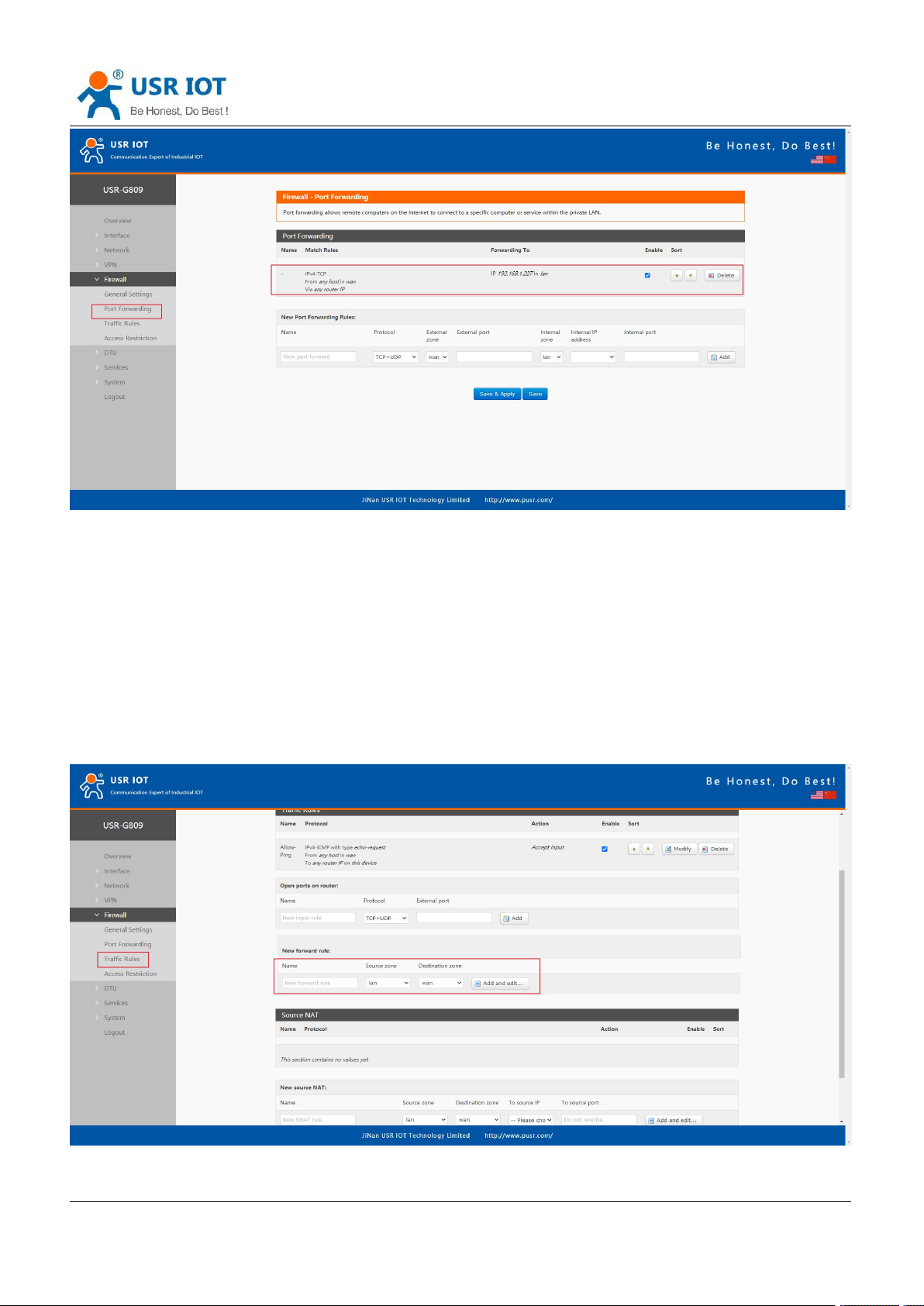
6.2.3.DMZ
Port forwarding rules map a specified WAN port to a intranet host, DMZ rules will map all ports of the WAN
interface to a intranet host.
DMZ rules are set in the port forwarding interface, in DMZ mode, do not need to set the external port and
internal port.
Click “Save&Apply”.
Page 43
USR-G809 User Manual Technical Support:
Jinan USR IOT Technology Limited www.pusr.com
43
All the ports of the WAN address will be forwarded to the intranet host 192.168.1.227.
Note: Port forwarding and DMZ cannot be used at the same time.
h.usriot.com
6.3. Traffic Rules
Traffic rules can filter specific internet data types and block internet access requests to enhance the security
of the network.
6.3.1.IP Address Blacklist
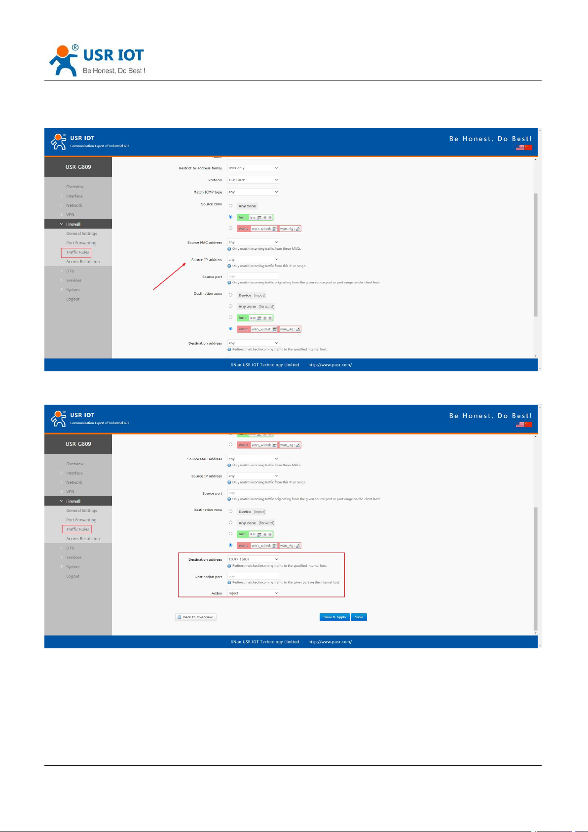
In “New forward rule”, enter the name then click “Add and edit”.
Page 44
USR-G809 User Manual Technical Support:
Jinan USR IOT Technology Limited www.pusr.com
44
h.usriot.com
In below interface, set the “Source zone” to “lan”, “Source MAC address” and “Source IP address” are
“any”(There are two methods to limit a specific LAN IP address to access a specific external IP address: fill in
the IP address or MAC address, the other one is any; or the IP address corresponds to the MAC address.)
Set the “Destination zone” to “wan”, “Destination address” is the IP address that restricted to be accessed.
Set the “Action” to “reject”, click “Save&apply”.
Page 45
Jinan USR IOT Technology Limited www.pusr.com
45
6.3.2.IP Address Whitelist
USR-G809 User Manual Technical Support:
h.usriot.com
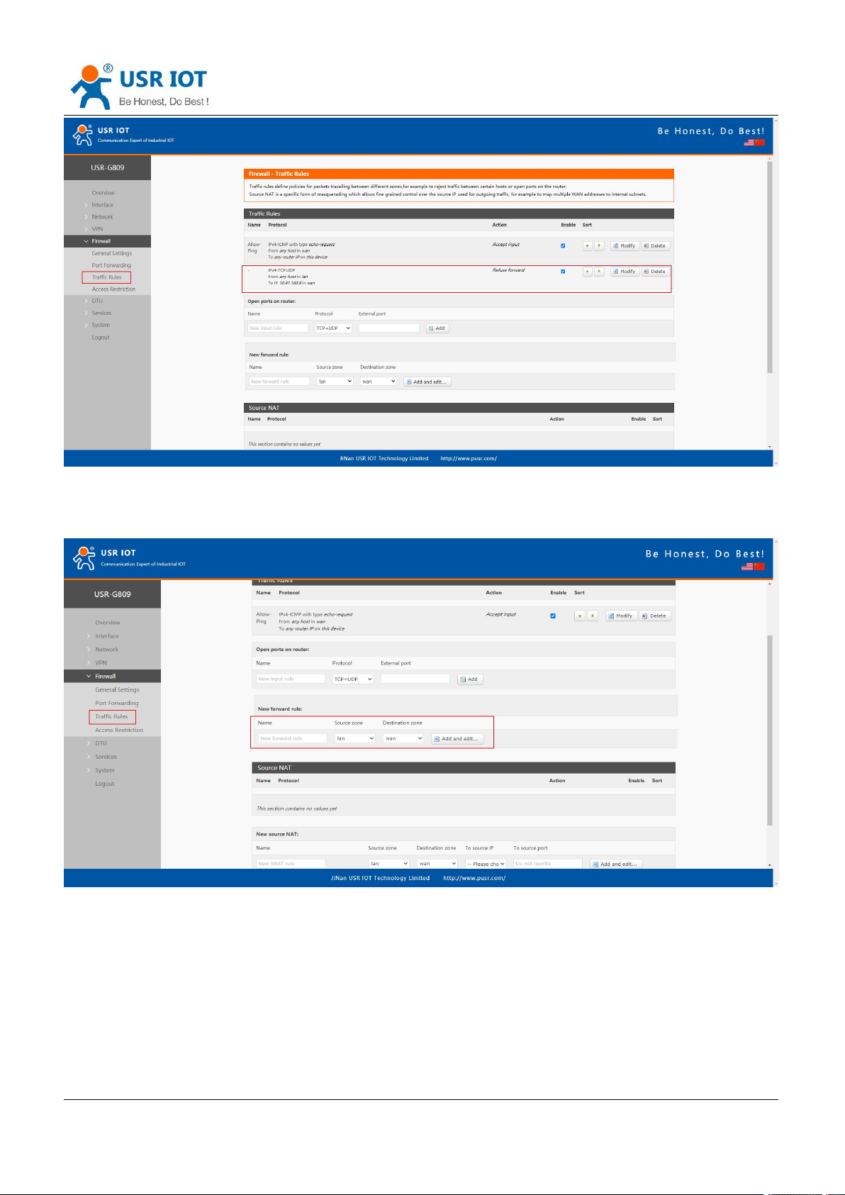
Enter the rule’s name, click “Add and edit” to create a whitelist.
In below interface, set the “Source zone” to “lan”, “Source MAC address” and “Source IP address” are
“any”(There are two methods to limit a specific LAN IP address to access a specific external IP address: fill in
the IP address or MAC address, the other one is any; or the IP address corresponds to the MAC address.)
Page 46
USR-G809 User Manual Technical Support:
Jinan USR IOT Technology Limited www.pusr.com
46
h.usriot.com
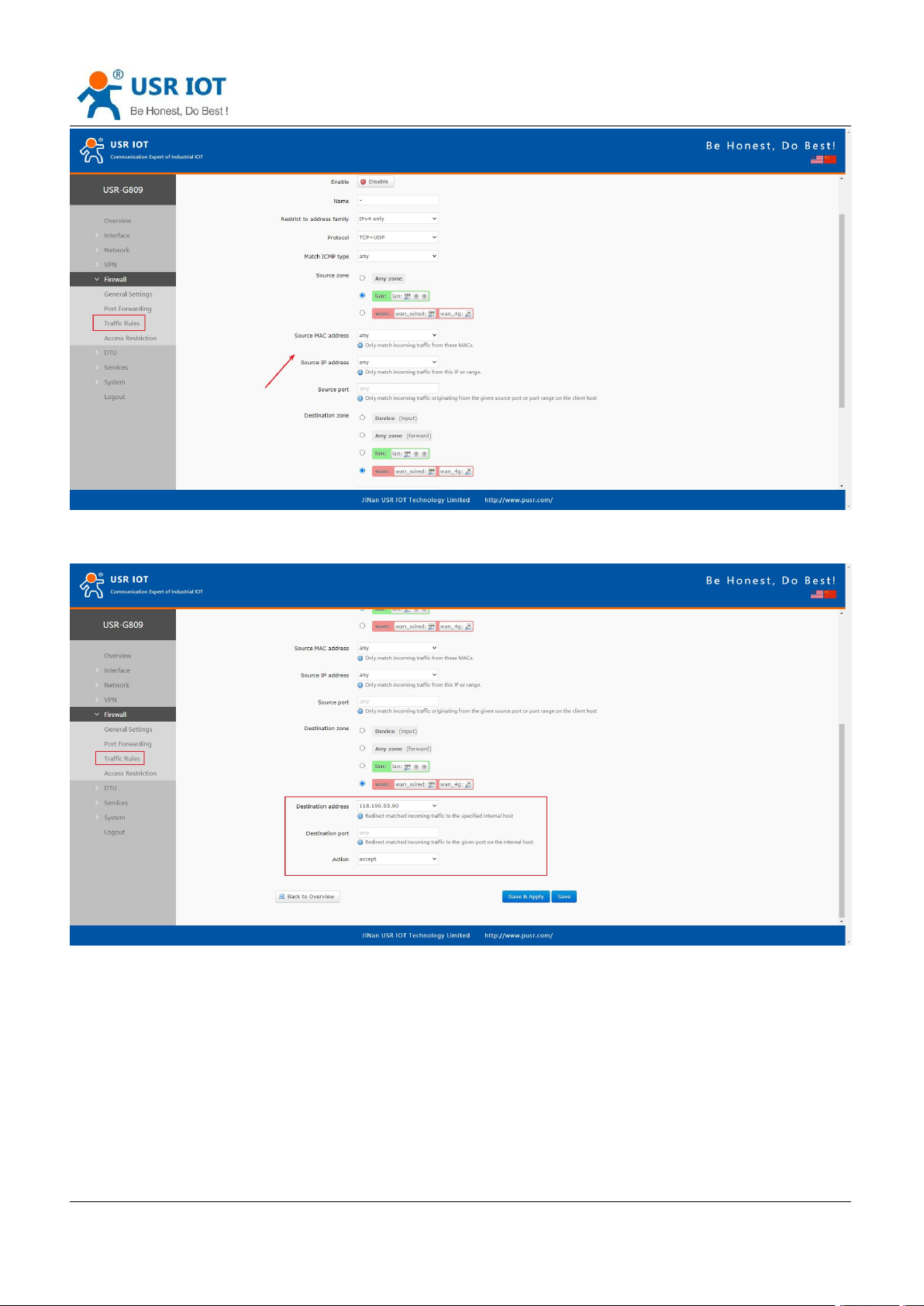
Set the “Destination zone” to “wan”, “Destination address” is the IP address that allowed to be accessed. Set
the “Action” to “accept”, click “Save&apply”.
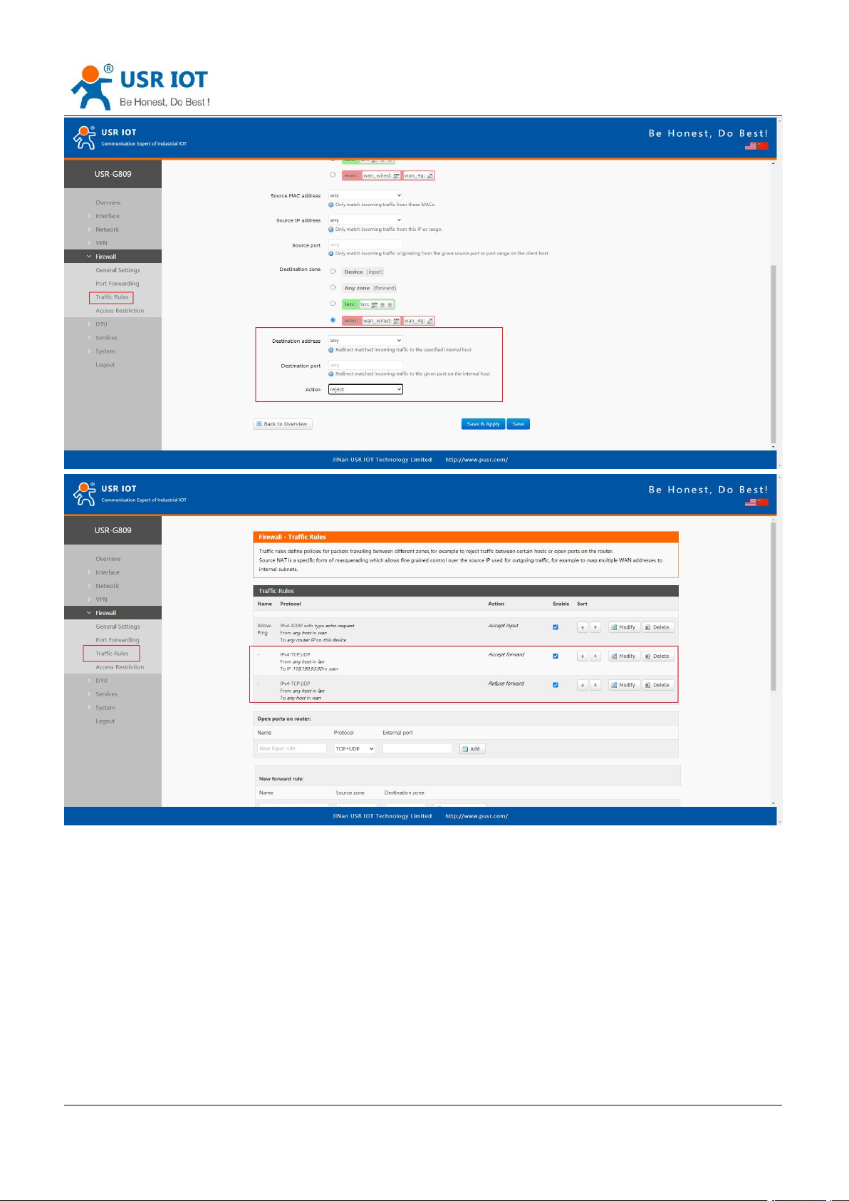
Then we need to set another rule to reject all the communication, the source IP address and destination IP
address are “any”, set the action to “reject”. Please note the order of the two rules, the accepted rule must
come before the rejected rule.
Page 47
USR-G809 User Manual Technical Support:
Jinan USR IOT Technology Limited www.pusr.com
47
h.usriot.com
6.3.3.IP and Port Access Restrictions
Add a forward rule.
Page 48
USR-G809 User Manual Technical Support:
Jinan USR IOT Technology Limited www.pusr.com
48
h.usriot.com
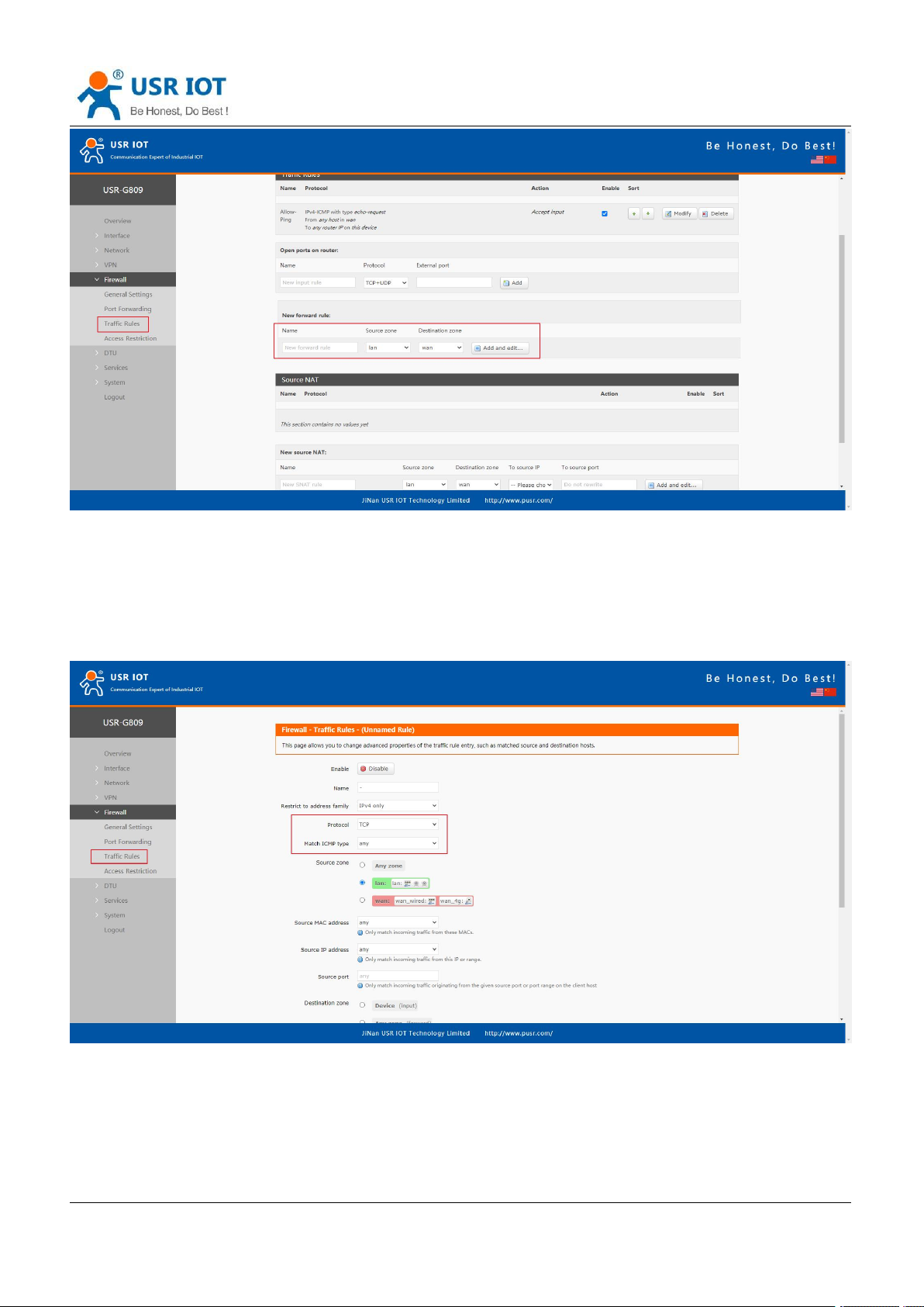
Protocol TCP+UDP: the specified source IP can ping the destination IP address, but cannot establish
TCP/UDP connection.
Protocol ICMP: the specified source IP cannot ping the destination IP address, but can establish
TCP/UDP connection.
Here we test with TCP protocol to disable a port of the LAN device from accessing a specified port of the
destination IP.
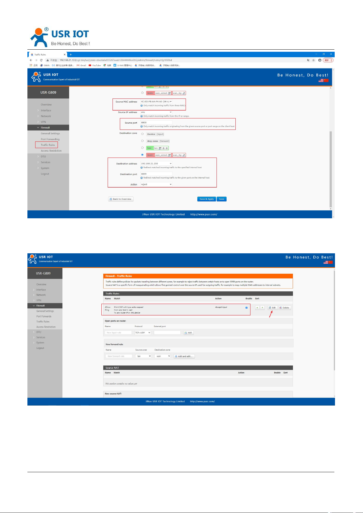
Leave the source zone as default, fill in the source IP address or MAC address.
Here we disable a device with the MAC 4C:ED:FB:6A:F4:60 and port 8800 from establishing TCP connection
with the destination IP 192.168.21.200 and port 8899.
Leave the source port and destination port to null means disable the TCP connection between the source
device(4C:ED:FB:6A:F4:60) and the destination address 192.168.21.200.
Page 49
USR-G809 User Manual Technical Support:
Jinan USR IOT Technology Limited www.pusr.com
49
h.usriot.com
6.3.4.Ping Restrictions
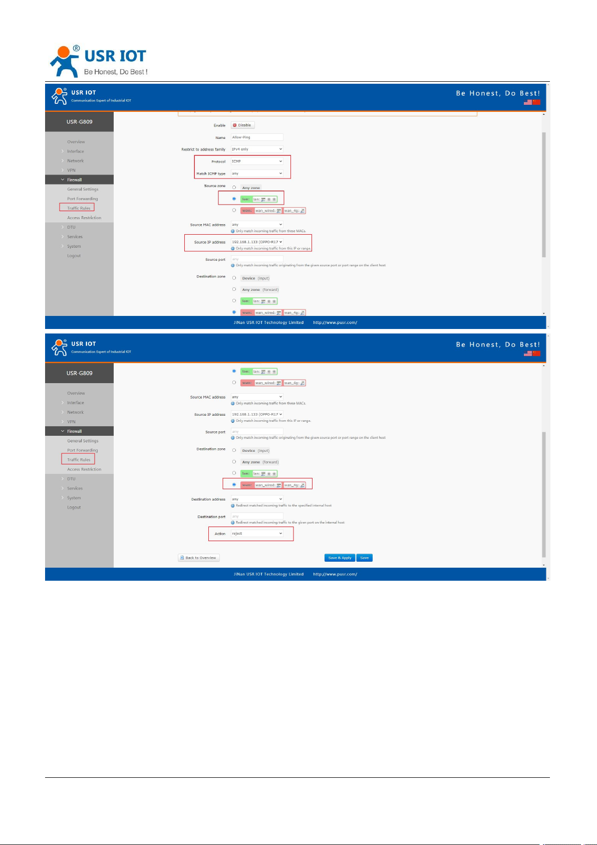
The device can be ping by default, users can disable the ping function by changing the default rules.
In below example, we disable the ping function from the LAN IP 192.168.1.133 to all the destination IP
addresses.
Page 50
USR-G809 User Manual Technical Support:
Jinan USR IOT Technology Limited www.pusr.com
50
h.usriot.com
Click “Save&Apply” to take the parameters effect.
6.4. Access Restriction
6.4.1.Black List
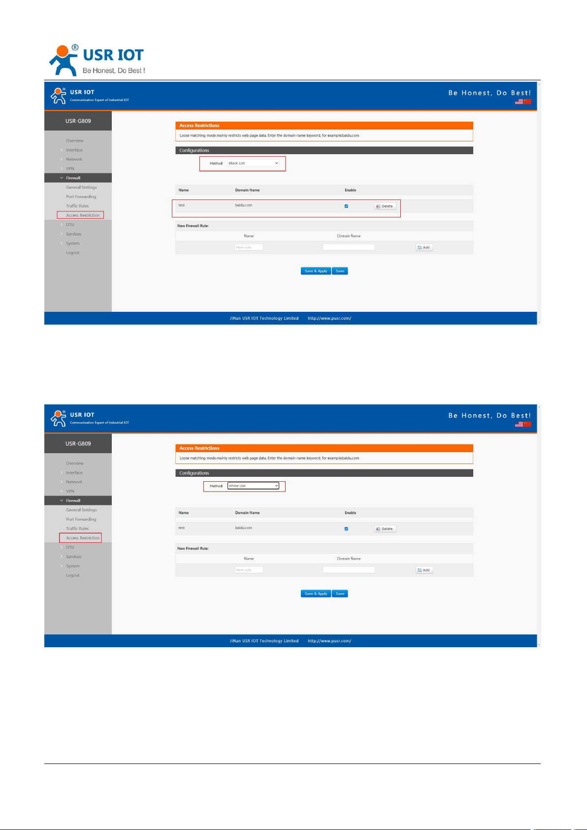
When we choose “Black list”, the devices connected to the router cannot access the domain name in blacklist,
but can access all other domain names. Here, the device can access the domain name except baidu.com.
Page 51
Jinan USR IOT Technology Limited www.pusr.com
51
6.4.2.White List
USR-G809 User Manual Technical Support:
h.usriot.com
After enable “White List”, the devices connected to the router can only access the domain name within
whitelist. If just enable white list but do not add the rules, the device cannot access any domain name. Here,
the device can only access baidu.com.
Page 52
USR-G809 User Manual Technical Support:
Jinan USR IOT Technology Limited www.pusr.com
52
h.usriot.com
7. Serial Port
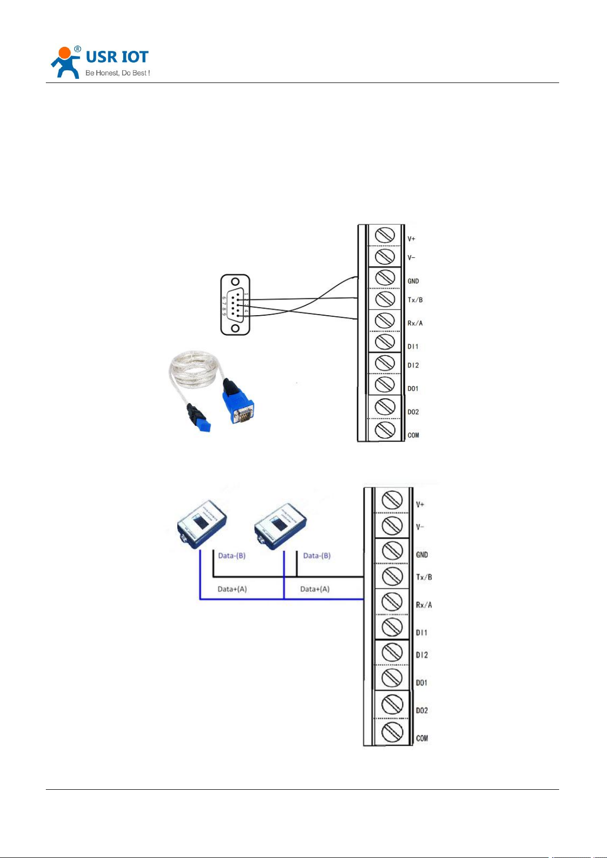
USR-G809 supports DTU function, which can achieve RS232 or RS485 serial data transmission.
7.1. Connecting Hardware
RS232:
RS485:
Page 53
Jinan USR IOT Technology Limited www.pusr.com
53
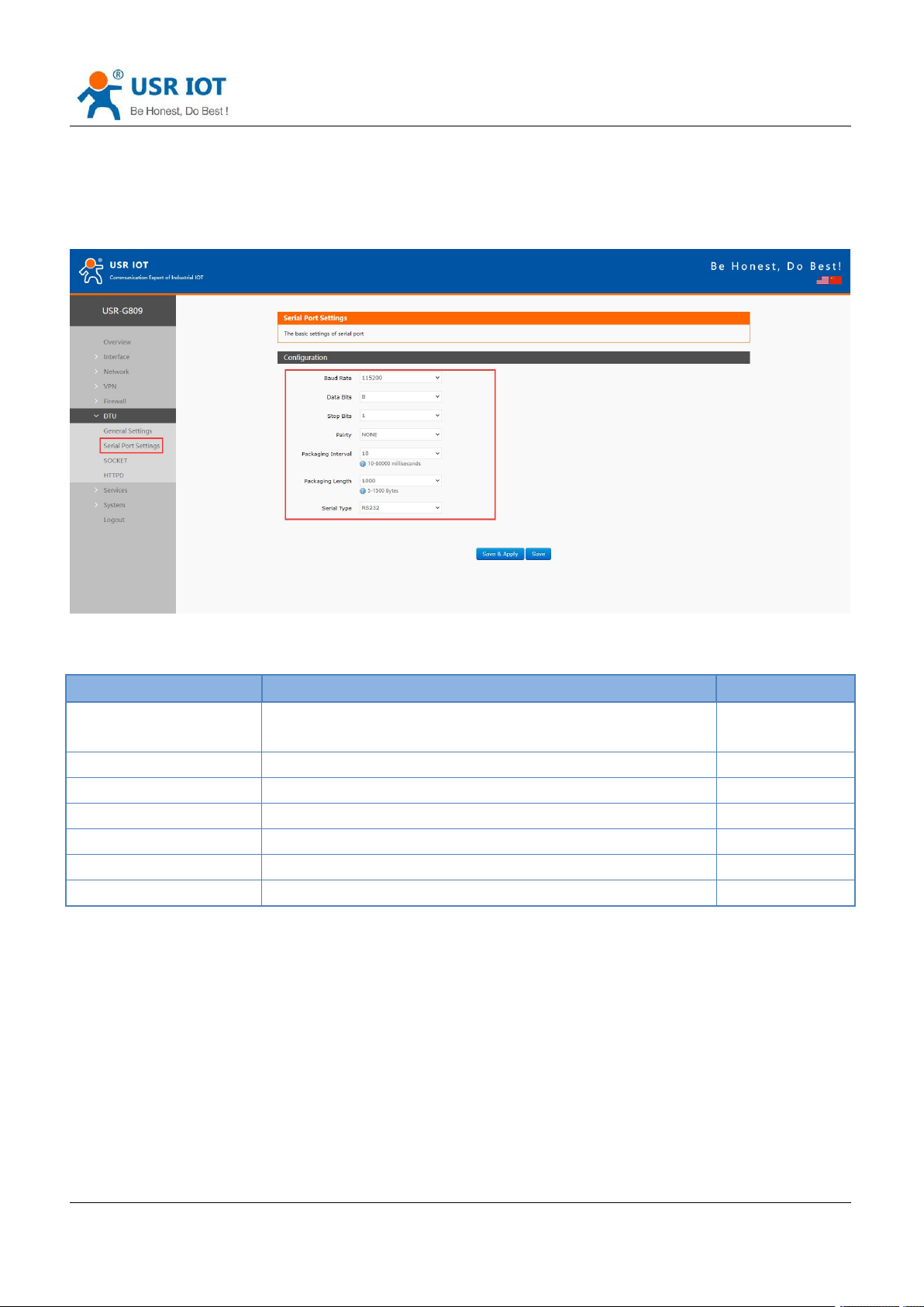
7.2. Serial Port Settings
Item
Description
Default
Baud rate
Supports
1200/2400/4800/9600/19200/38400/57600/115200/230400
115200
Data bits
8
8
Stop bits
1 /2
1
Parity
NONE/ODD/EVEN
NONE
Packaging interval (ms)
10-60000
10
Packaging length(byte)
5-1500
1000
Serial type
RS232/RS485
RS232
7.2.1.Basic Settings
USR-G809 User Manual Technical Support:
h.usriot.com
Serial parameters of USR-G809 must be consistent with the RS232 or RS485 serial device. Otherwise, they
cannot communicate with each other.
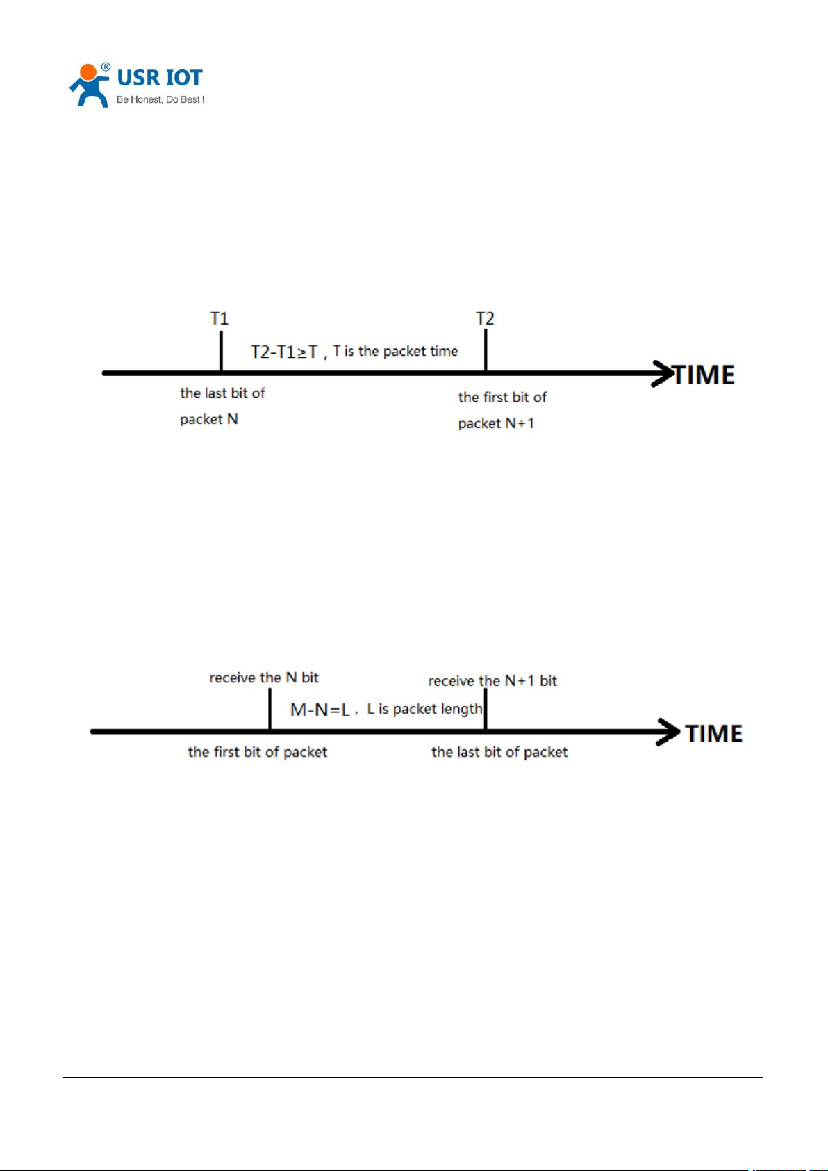
7.2.2.Framing Mechanism
Page 54
USR-G809 User Manual Technical Support:
Jinan USR IOT Technology Limited www.pusr.com
54
7.2.2.1. Time Trigger
When G809 receives data from the UART, it continuously checks the interval of two adjacent bytes. If the
interval time is greater or equal to a certain "time threshold", then a frame is considered finished, otherwise
the data is received until greater or equal to the packet length byte set (Defaults to 1000 bytes). This frame is
sent to the network as a TCP or UDP packet. The "time threshold" here is the time between packages. The
range of settable is 10ms~60000ms.Factory default: 10ms.
This parameter can be set by AT command, AT+UARTFT=<time>.
7.2.2.2. Length Trigger
h.usriot.com
When G809 receives data from the UART, it constantly checks the number of bytes received. If the number of
bytes received is equal to a certain "length threshold", a frame is considered to have ended, then this frame is
sent to the network as a TCP or UDP packet. The "length threshold" here is the package length. The settable
range is 5~1500 bytes. Factory default 1000.
This parameter can be set by AT command, AT+UARTFL=<length>.
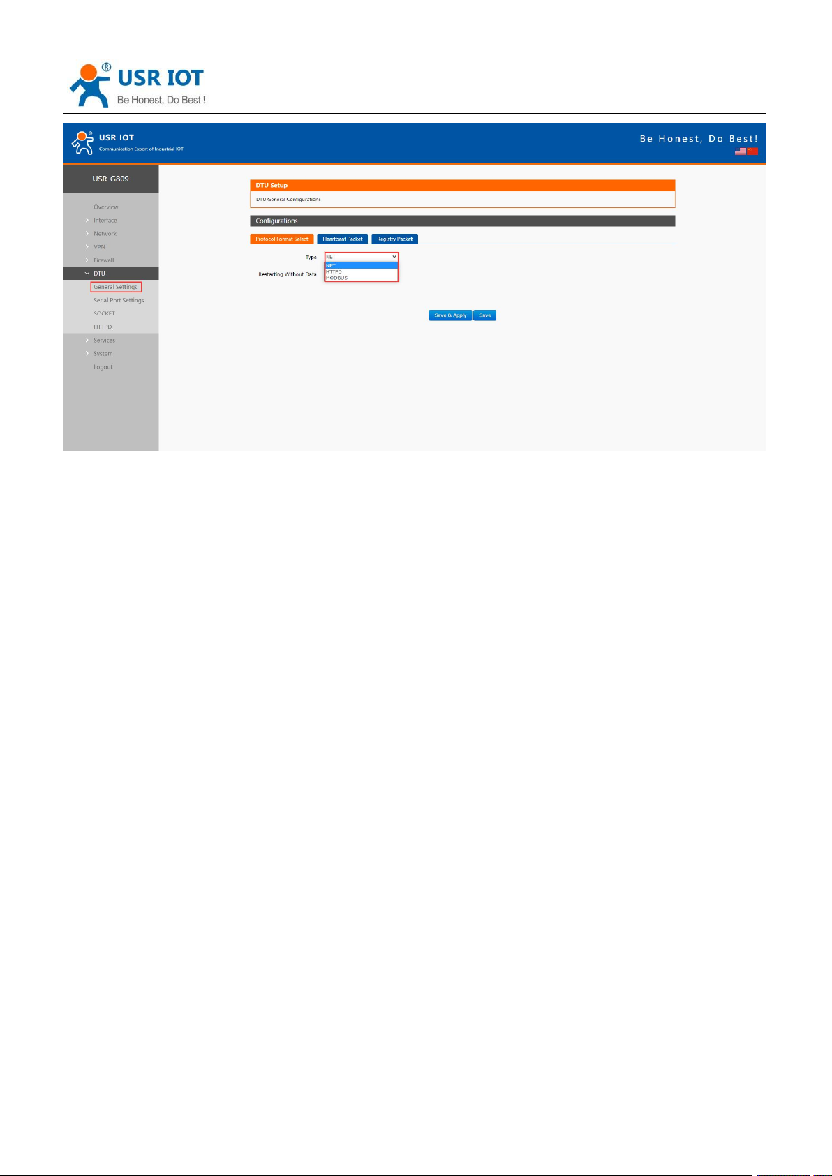
7.3. Operation Mode
USR-G809 supports three operation modes: NET(Transparent transmission), MODBUS(MODBUS RTU to
MODBUS TCP), HTTPD(HTTP Client mode).
Page 55
Jinan USR IOT Technology Limited www.pusr.com
55
7.3.1.NET Mode
USR-G809 User Manual Technical Support:
h.usriot.com
In this mode, user can achieve transparent data transmission between the serial device and the network
server with simple parameter settings.
USR-G809 supports 4 socket connections, socket A~socket D, which are independent with each other.
Socket A supports TCP client/TCP server, UDP client/server, socket B/C/D supports TCP client, UDP
client/server.
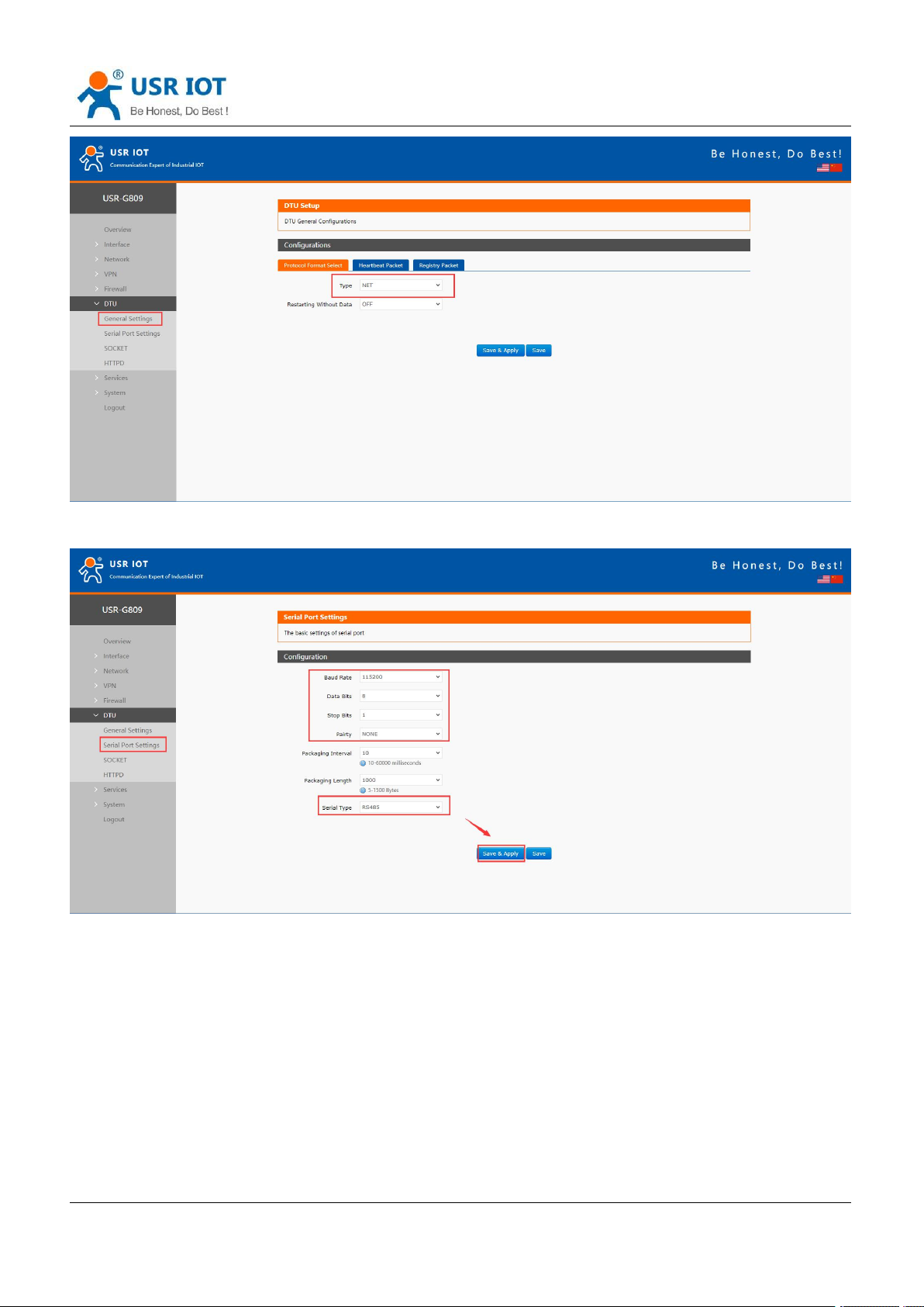
Here we connect the RS485 port to the computer via a serial to USB adaptor to test:
1. Set the operation mode to NET.
Page 56
Jinan USR IOT Technology Limited www.pusr.com
56
2. Set the serial port parameters.
USR-G809 User Manual Technical Support:
h.usriot.com
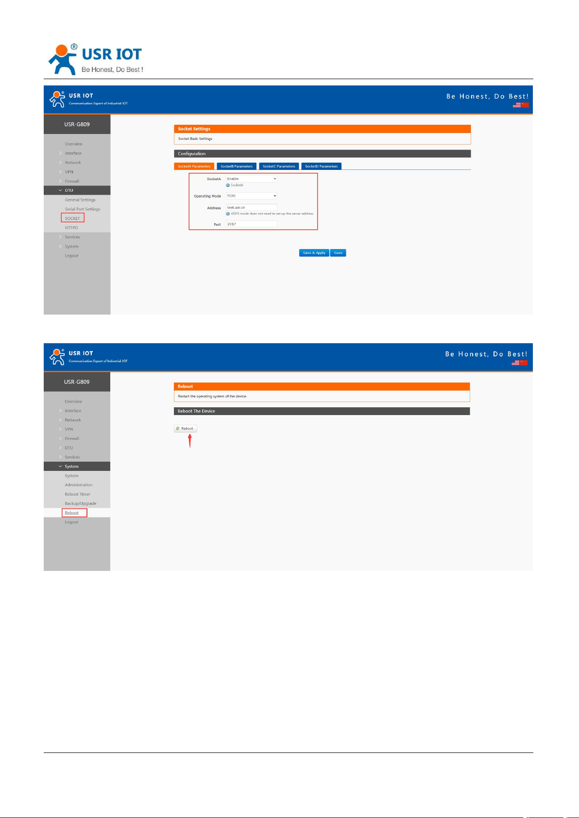
3. Set the device to TCP client, server address to test.usr.cn, port 2317.
Page 57
USR-G809 User Manual Technical Support:
Jinan USR IOT Technology Limited www.pusr.com
57
4. After setting all parameters, restart the device to take the parameters effect.
h.usriot.com
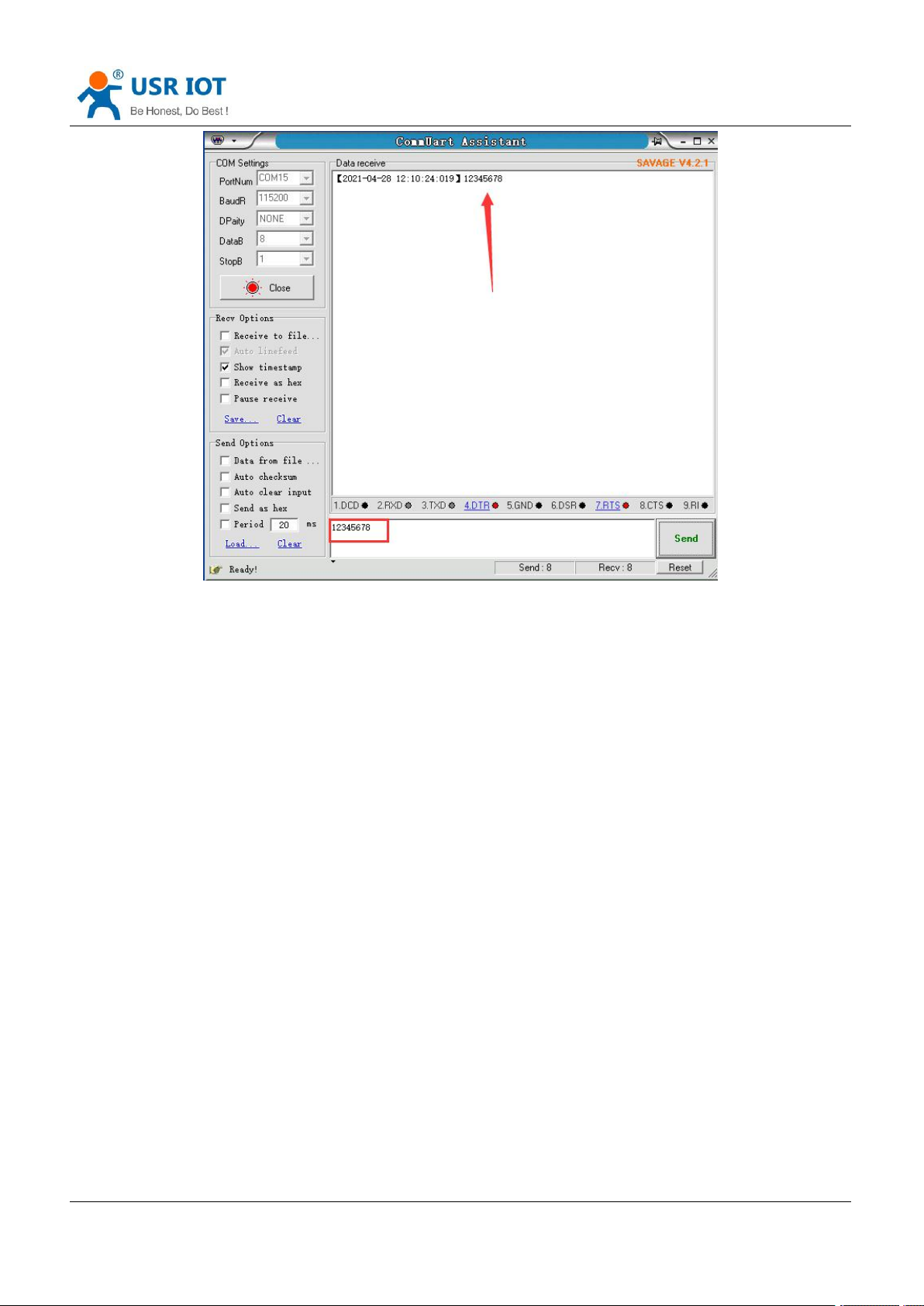
5. After the device restarts, when we send data from the serial port, will receive the same data replied by
the test server.
Page 58
USR-G809 User Manual Technical Support:
Jinan USR IOT Technology Limited www.pusr.com
58
h.usriot.com
7.3.2.MODBUS Mode
In this mode, USR-G809 can achieve bidirectional protocol conversion between serial MODBUS RTU data
and network MODBUS TCP data.
MODBUS mode supports 4 socket connections, which are independent with each other.
Socket A supports TCP client/server, socket B/C/D only supports TCP client.
7.3.3.HTTPD Mode
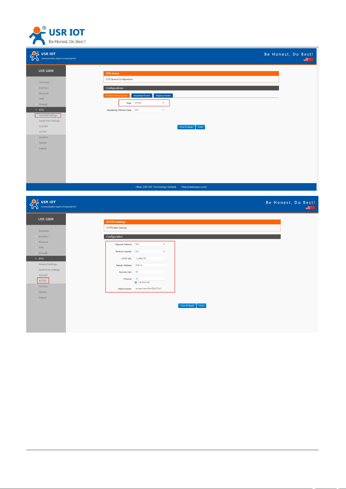
In this mode, user’s serial device can send request data to the HTTP server. USR-G809 will resolve the
server data then send to serial device. It will remove the HTTP header of the server data by default, users can
set whether to enable this function via AT commands.
Page 59
USR-G809 User Manual Technical Support:
Jinan USR IOT Technology Limited www.pusr.com
59
h.usriot.com
7.4. General Function
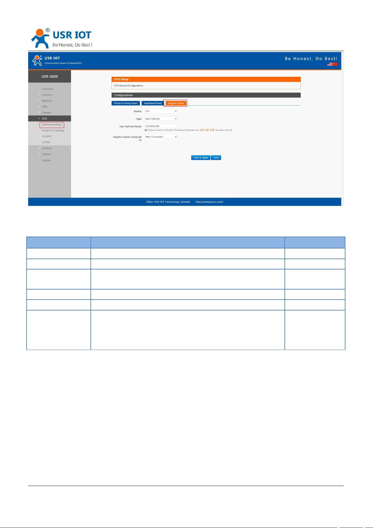
7.4.1.Registry Packet
Registry packet is intended to allow the server to identify the data from which device or to use it as a
password to obtain authorization for the server's functions. Registry packet can be sent when the module
establishes a connection with the server, or be added as the prefix of each data package. Registry packet
data can be ICCID code, IMEI code, or User-defined data.
Page 60
USR-G809 User Manual Technical Support:
Jinan USR IOT Technology Limited www.pusr.com
60
Item
Description
Default
Enable
ON/OFF
OFF
Type
IMEI, ICCID, USR Cloud, User-Defined
User-Defined
User-Defined
packet
A-F, a-f, 0-9, hex data, even bit
0123456789
Cloud ID
Registry packet parameters of USR Cloud
SN code
Cloud psw
Registry packet parameters of USR Cloud
12345678
Registry packet
contained in
After connection: Send once when establish a connection with
the server.
Prefix of data: Registry packet is added as the prefix of each
data packet.
After connection
h.usriot.com
Note: Registry packet is only valid in TCPC, UDPC mode.
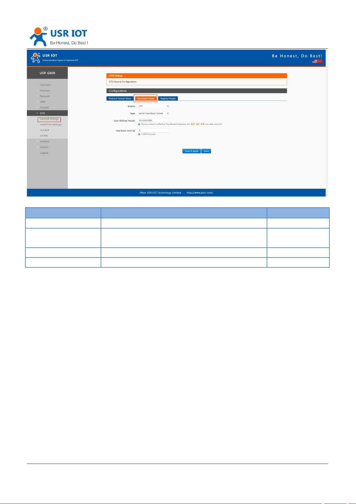
7.4.2.Heartbeat Packet
Heartbeat package can be sent to the network or serial port device. G809 defaults to send to the network to
keep the connection stable and reliable.
Page 61
USR-G809 User Manual Technical Support:
Jinan USR IOT Technology Limited www.pusr.com
61
Item
Description
Default
Enable
ON/OFF
OFF
Type
Serial heartbeat packet/Network heartbeat packet
Network heartbeat
packet
User-defined packet
A-F, a-f, 0-9, hex data, even bit
0123456789
Heartbeat interval (s)
1-6000s
3
h.usriot.com
Note: Heartbeat packet is only valid in TCPC, UDPC mode.
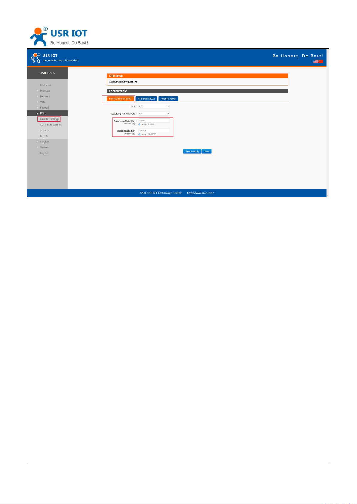
7.4.3.Restarting Without Data
This function defaults to be disabled. When it is enabled, the device can actively disconnect the connection
with the server and reconnect when there is no data from network side within the reconnect detection interval,
which can prevent pseudo-connection due to an abnormal socket disconnection.
When the time reaches the restart detection interval, the device will restart automatically to recover the
connection.
Page 62
USR-G809 User Manual Technical Support:
Jinan USR IOT Technology Limited www.pusr.com
62
Note:
After parameters settings, restart the device to take the parameters effect.
This function is only valid in NET/MODBUS mode.
h.usriot.com
7.4.4.RFC2217
Page 63
USR-G809 User Manual Technical Support:
Jinan USR IOT Technology Limited www.pusr.com
63
Item
Header
Baud rate
Bit
Parity
Bytes
331
1
Description
3 bytes reduce
misjudgment
A baud rate
value, high first
Please check below
table
Parity of the first
four digits,
ignoring carry.
h.usriot.com
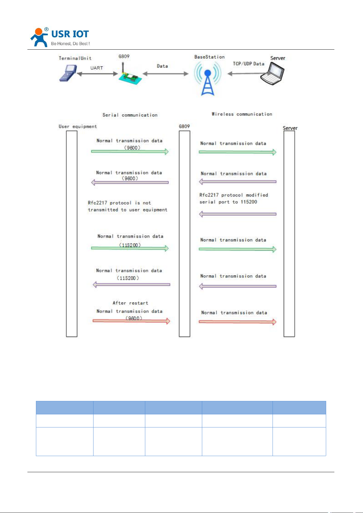
This function is similar to RFC2217, when we send the specific protocol data from the network side, can
change the serial parameters in real time. Parameters take effect immediately, but it will be restored to the
original after restarting.
Protocol description:
The protocol length is 8 bytes in HEX:
Page 64

USR-G809 User Manual Technical Support:
Jinan USR IOT Technology Limited www.pusr.com
64
Example:
(115200,N,8,1)
55 AA 55
01 C2 00
83
46
Example:
(9600,N,8,1)
55 AA 55
00 25 80
83
28
Bit
Description
Value
Description
1:0
Data bit
00
5
01
6
10
7
11
8
2
Stop bit
0
1
1
2
3
Parity
0
Disable
1
Enable
5:4
Parity type
00
ODD
01
EVEN
10
Mark
7:6NC00
0
h.usriot.com
Note: This function needs to be enabled via AT command: AT+RFCEN.
Page 65
USR-G809 User Manual Technical Support:
Jinan USR IOT Technology Limited www.pusr.com
65
h.usriot.com
8. USR Cloud
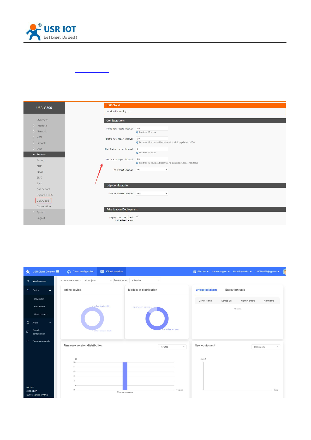
USR Cloud address: mp.usriot.com (Please register an account first)
USR-G809 enables USR Cloud service by default. User can configure the traffic flow record parameters, net
status parameters and heartbeat parameters. It also support reporting the device status to the USR Cloud
with privatization.
8.1. Cloud Monitor
Cloud monitor displays the online devices, models, firmware version, alarm information and new device.
Page 66
USR-G809 User Manual Technical Support:
Jinan USR IOT Technology Limited www.pusr.com
66
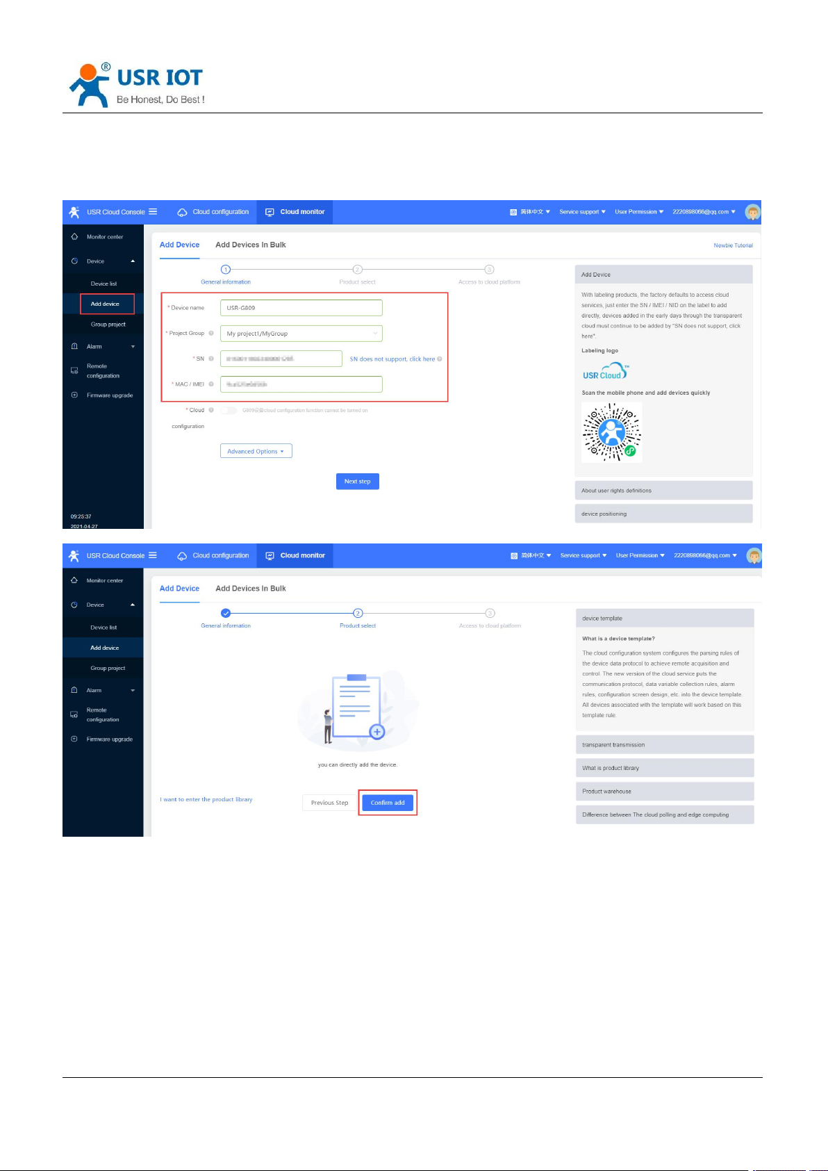
8.2. Add device
Please add the device according to the device MAC/IMEI and SN in the label.
h.usriot.com
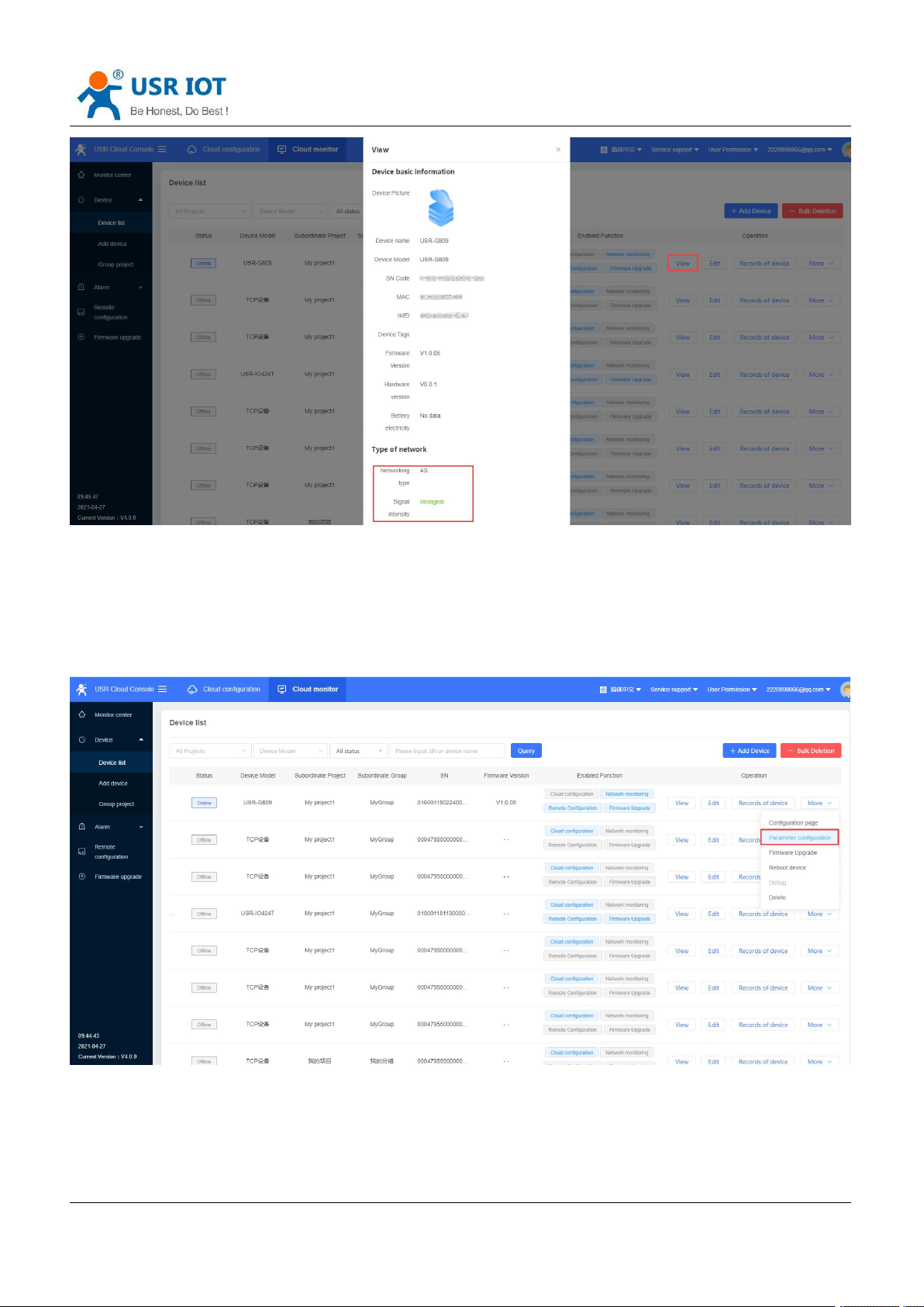
8.3. Network Status
In “Device List”, click “View”, it will show the network status of the device.
Page 67
USR-G809 User Manual Technical Support:
Jinan USR IOT Technology Limited www.pusr.com
67
h.usriot.com
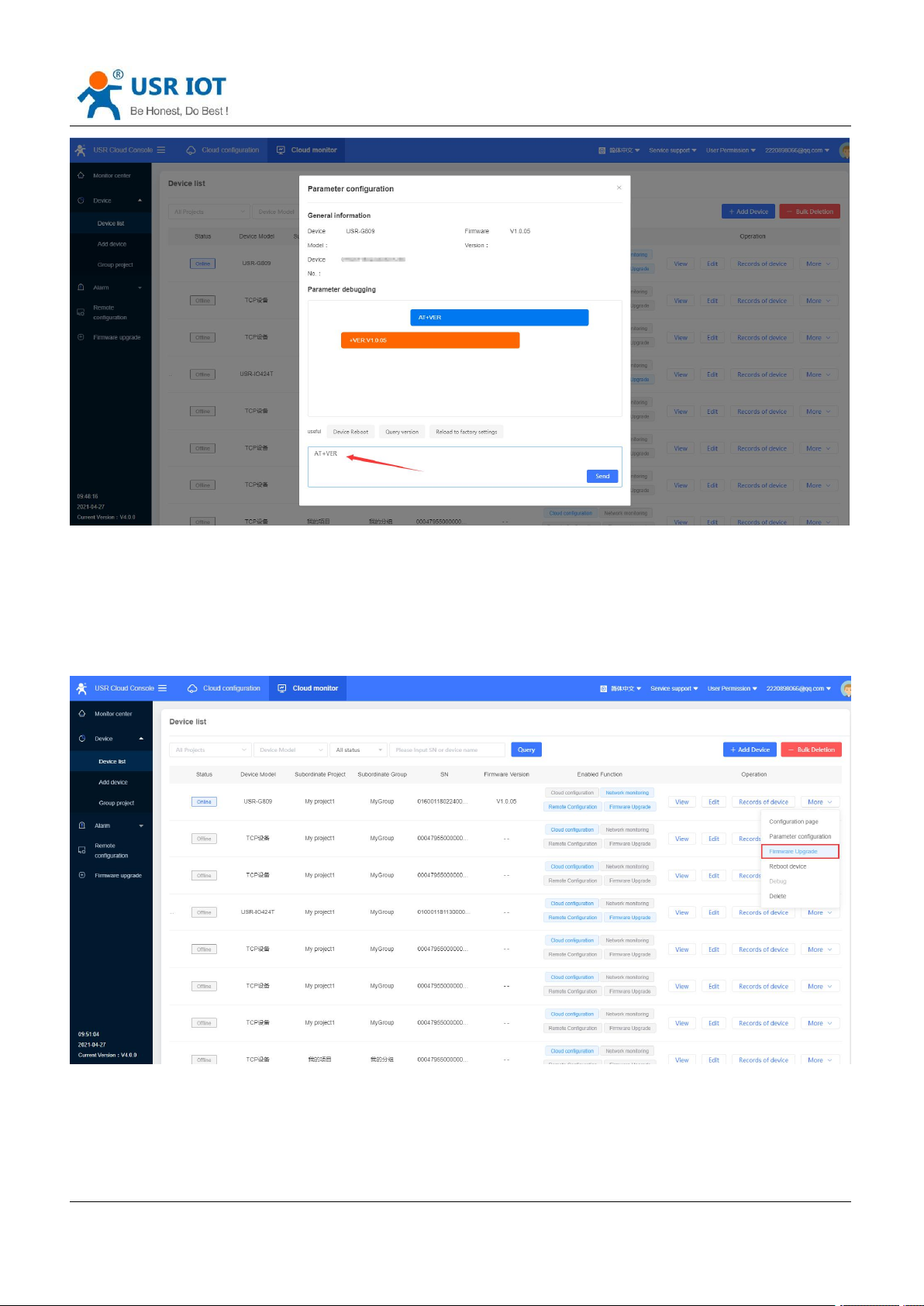
8.4. Parameter Configuration
Users can configure the device parameters via AT commands from USR Cloud.
1. In “Cloud monitor---Device list--More”, click “Parameter configuration”.
2. Can send AT commands to query or configure the device parameters via AT commands.
Page 68
USR-G809 User Manual Technical Support:
Jinan USR IOT Technology Limited www.pusr.com
68
h.usriot.com
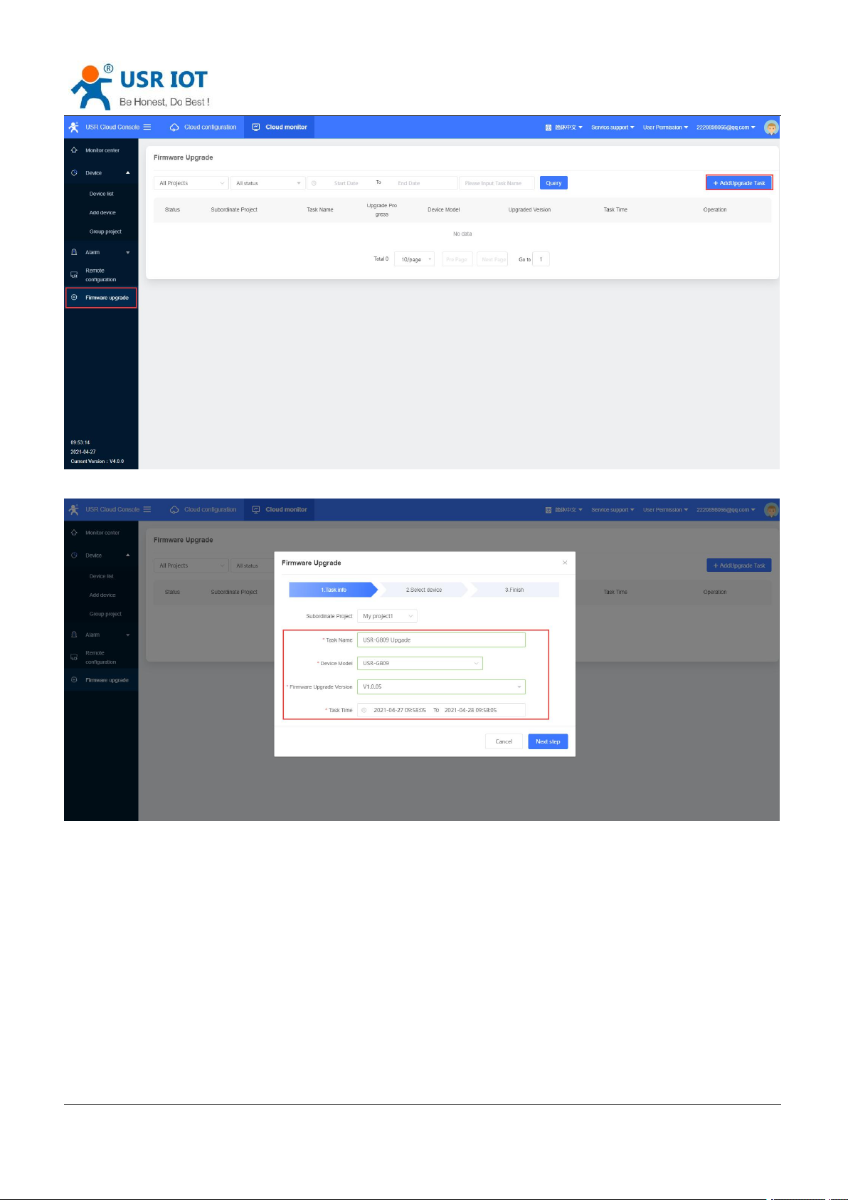
8.5. Firmware Upgrade
USR-G809 supports upgrading firmware via USR Cloud.
1. In “Device list---More”, click “Firmware Upgrade”.
Or can directly click “Firmware Upgrade” under “Cloud Monitor”, then click “Add upgrade task”.
Page 69
USR-G809 User Manual Technical Support:
Jinan USR IOT Technology Limited www.pusr.com
69
2. Fill in the task name, device model, firmware version, task name, then click “Save”.
h.usriot.com
3. You can also check the current firmware upgrade progress in “Upgrade Details”.
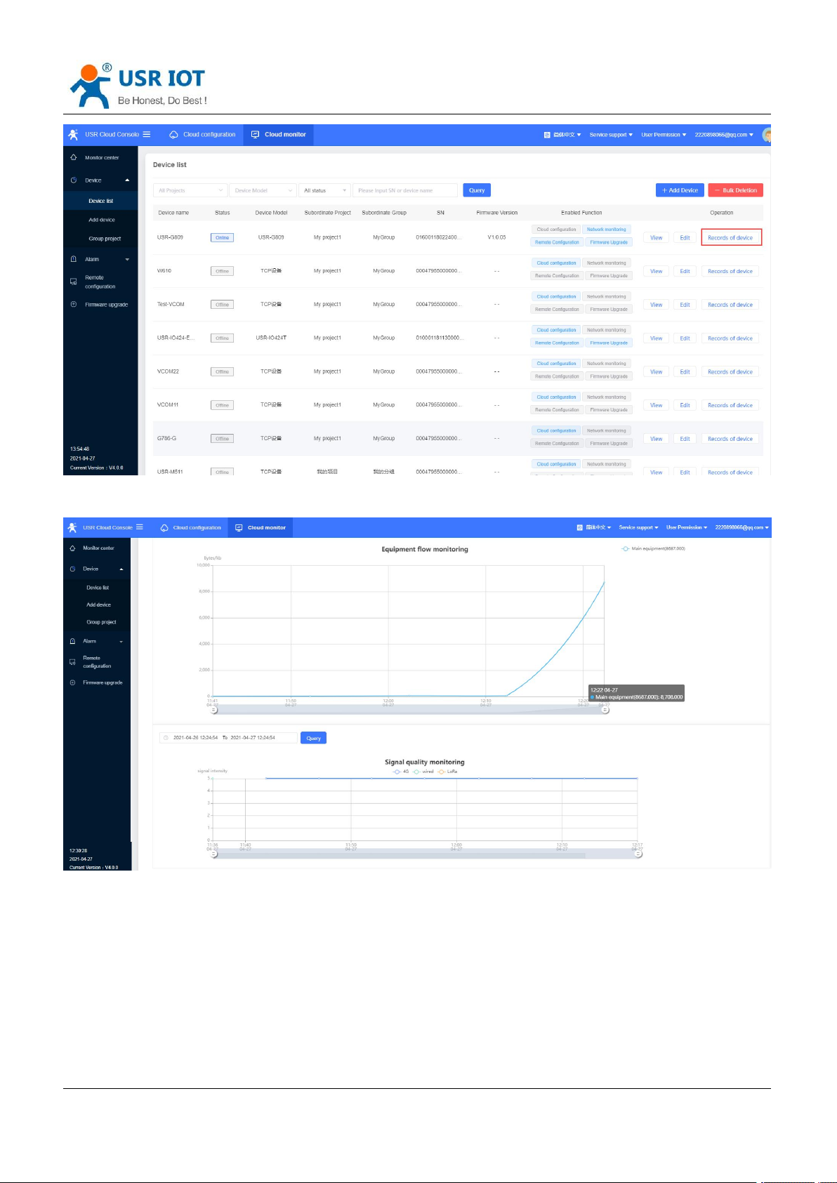
8.6. Records of device
USR Cloud can record all the status information during the operation of the device, including configuration
records, update records, signal strength and so on.
In “Cloud monitor--Device List”, click “Records of device”.
Page 70
USR-G809 User Manual Technical Support:
Jinan USR IOT Technology Limited www.pusr.com
70
You can check the traffic curve, signal strength curve under “Device Monitoring”.
h.usriot.com
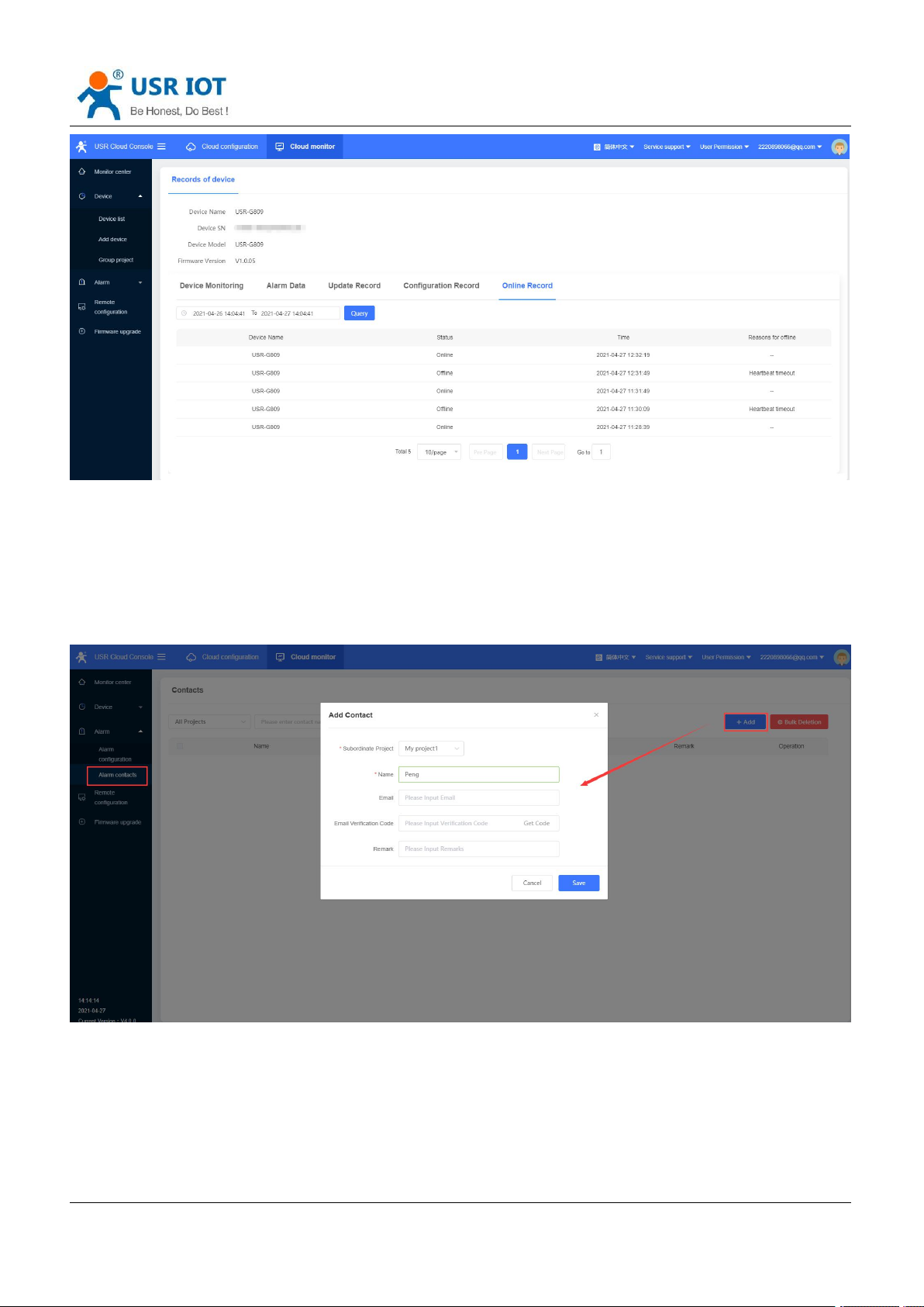
Online Record:
Page 71
Jinan USR IOT Technology Limited www.pusr.com
71
8.7. Alarm
USR-G809 User Manual Technical Support:
h.usriot.com
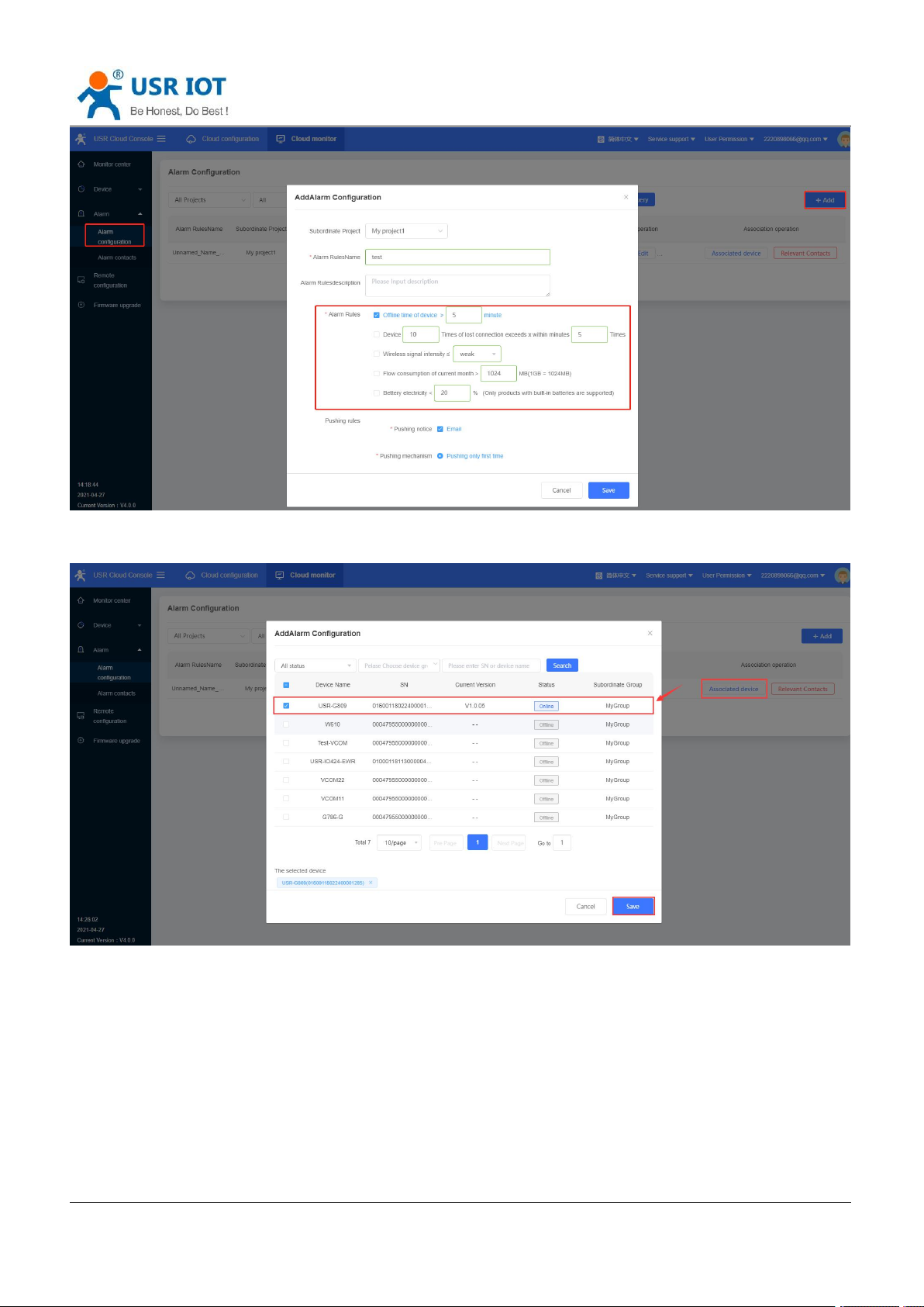
USR Cloud can achieve alarm via device status, like device offline, weak signal strength, traffic consumption
exceeds the set value.
1. Add the alarm contacts in “Cloud Monitor--Alarm contacts”.
2. Add alarm configuration in “Device monitor--Alarm configuration”. Here we can set the alarm rules to
“Offline time of device >5min”, push it via email.
Page 72
USR-G809 User Manual Technical Support:
Jinan USR IOT Technology Limited www.pusr.com
72
3. Add the associated device, then click “Save”.
h.usriot.com
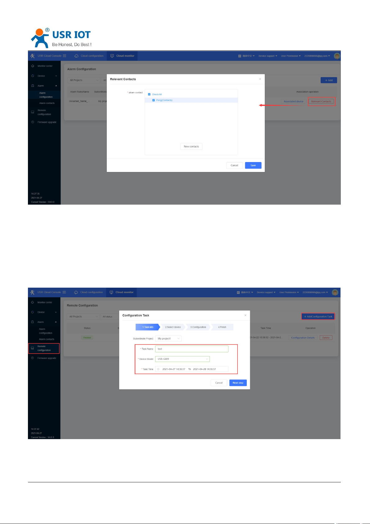
4. Add the relevant contacts.
Page 73
USR-G809 User Manual Technical Support:
Jinan USR IOT Technology Limited www.pusr.com
73
5. Power off the device, we will receive the alarm email from USR Cloud.
h.usriot.com
8.8. Remote Configuration
8.8.1.Configure via AT Commands
USR-G809 supports remote configuration via AT commands.
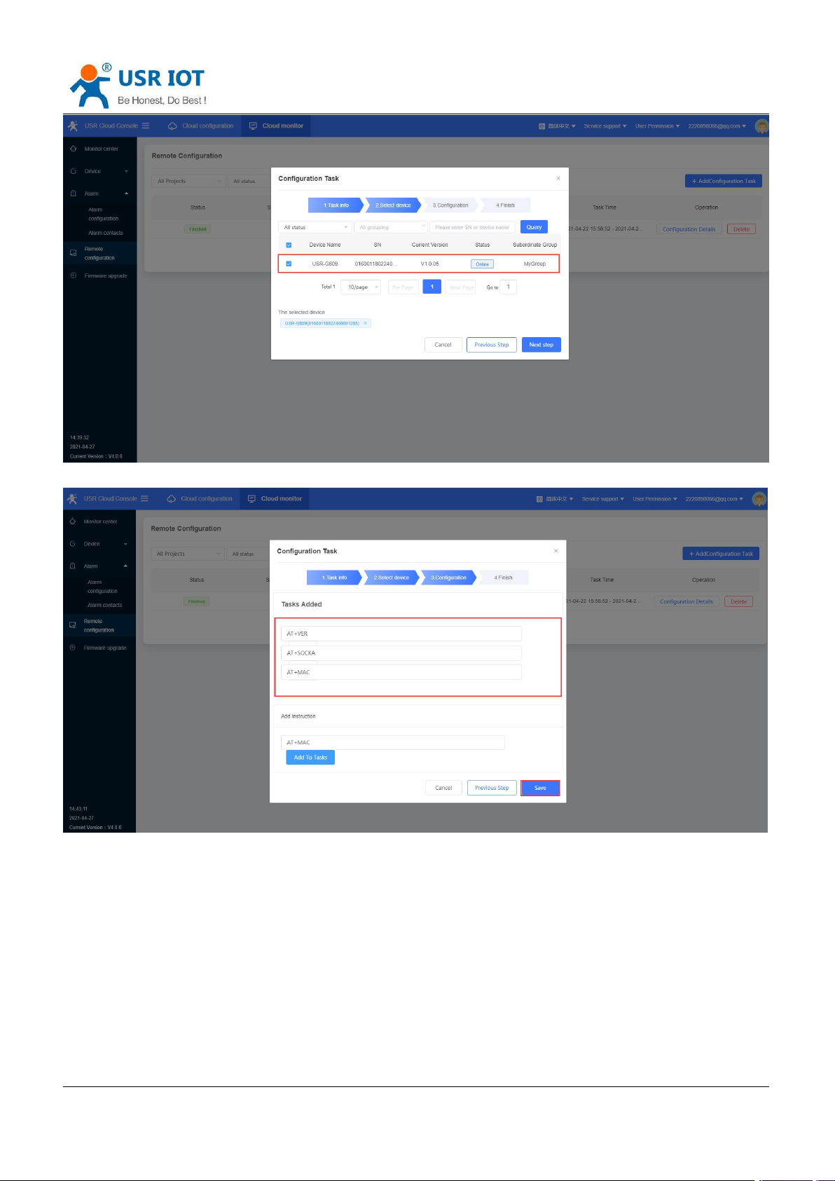
1. Add tasks in “Remote Configuration”. Set the device model to “USR-G809”.
2. Click “Next step”, it will show all the devices with this model.
Page 74
USR-G809 User Manual Technical Support:
Jinan USR IOT Technology Limited www.pusr.com
74
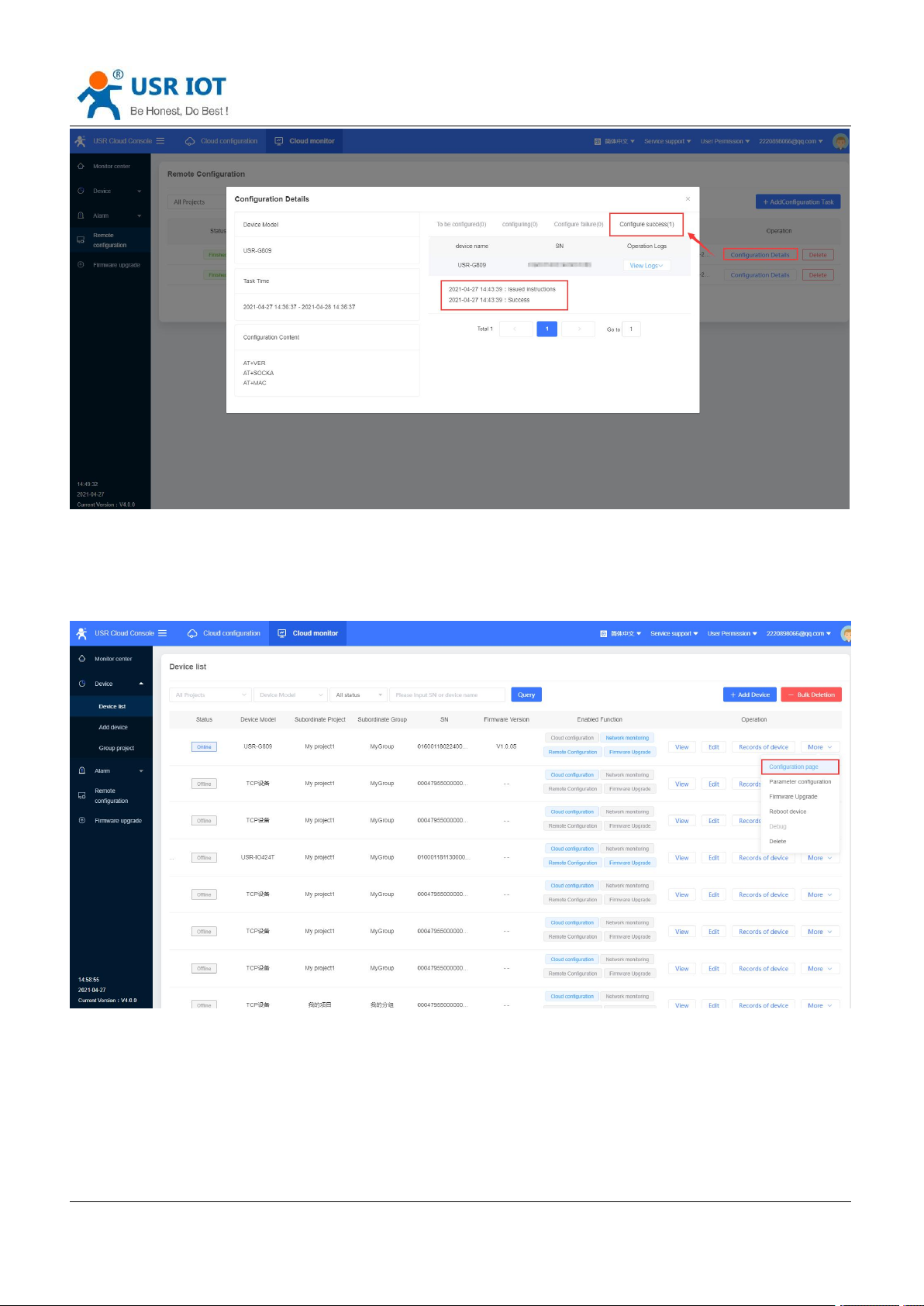
3. Add the commands to tasks, then click “Save”.
h.usriot.com
4. We can check the logs in “Configuration Details”.
Page 75
USR-G809 User Manual Technical Support:
Jinan USR IOT Technology Limited www.pusr.com
75
8.8.2.Configure via Webpage
h.usriot.com
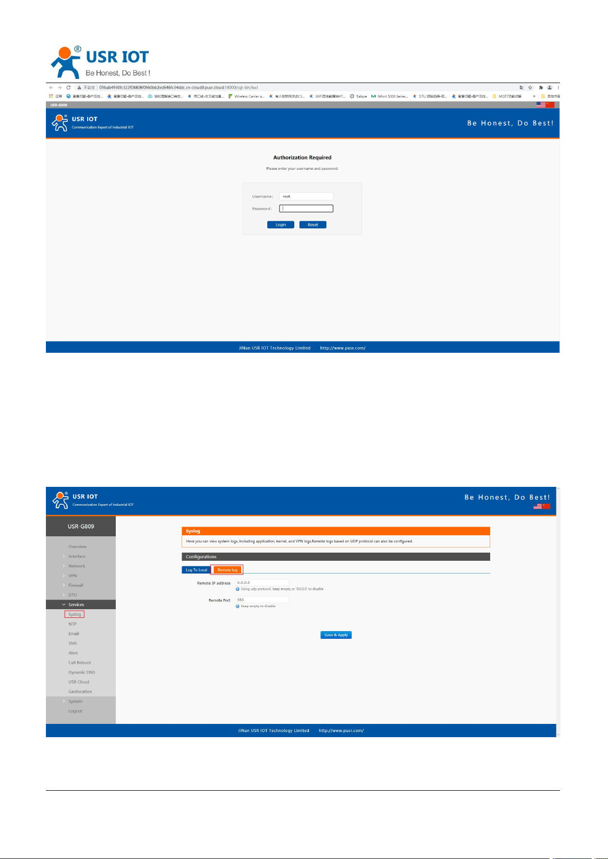
Users can log into G809’s webpage to configure the device via USR Cloud.
In “Device Monitor--Device list”, click “More”, select “Configuration page”.
Page 76
USR-G809 User Manual Technical Support:
Jinan USR IOT Technology Limited www.pusr.com
76
h.usriot.com
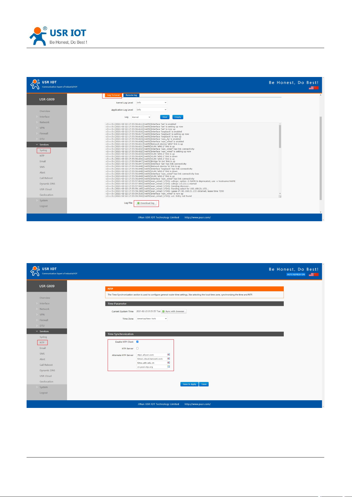
9. Services
9.1. Syslog
9.1.1.Remote Log
Remote IP address: Remote UDP server IP/domain name, this function is disabled when the IP is 0.0.0.0.
Remote port: Remote UDP server port.
Page 77
USR-G809 User Manual Technical Support:
Jinan USR IOT Technology Limited www.pusr.com
77
9.1.2.Local Log
We can view and download the router logs in below interface.
h.usriot.com
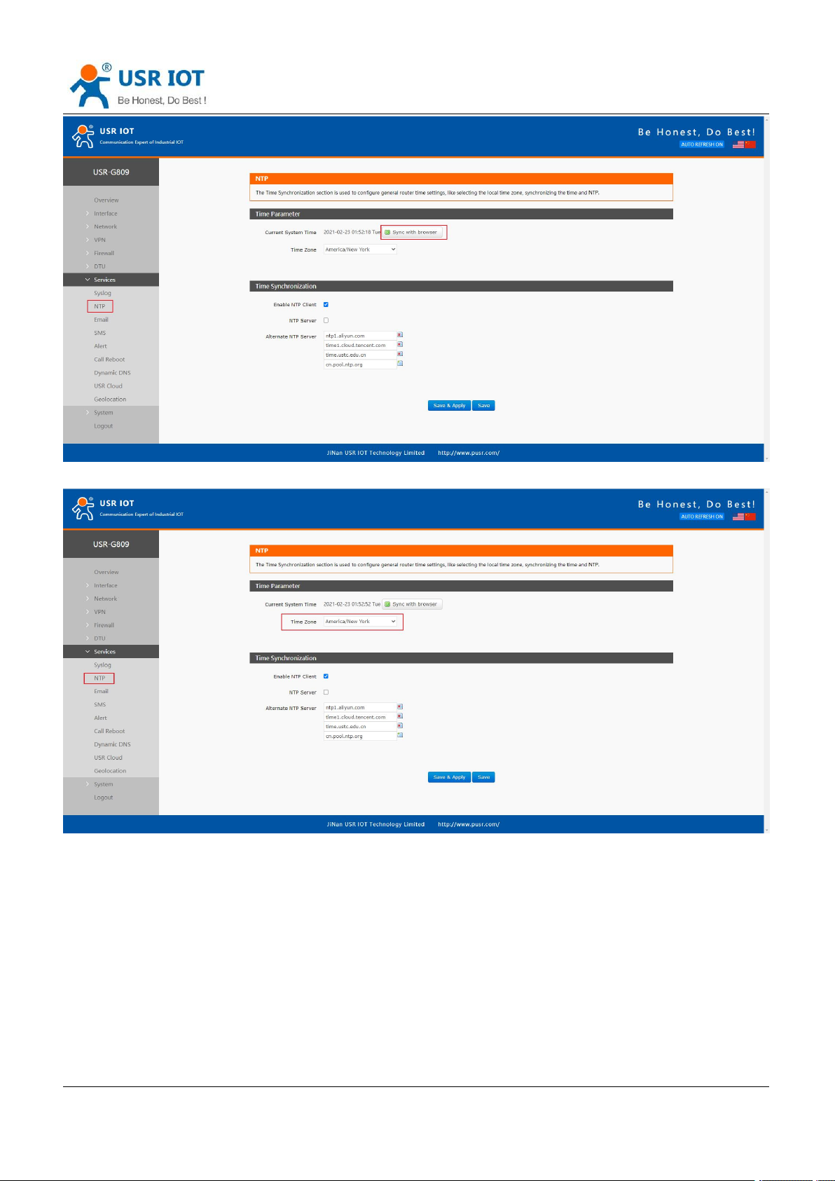
9.2. NTP
NTP client function is enabled by default, user can also set the NTP server addresses.
Click “Sync with browser” to synchronize the time of the browser.
Page 78
Jinan USR IOT Technology Limited www.pusr.com
78
Change the time zone:
USR-G809 User Manual Technical Support:
h.usriot.com
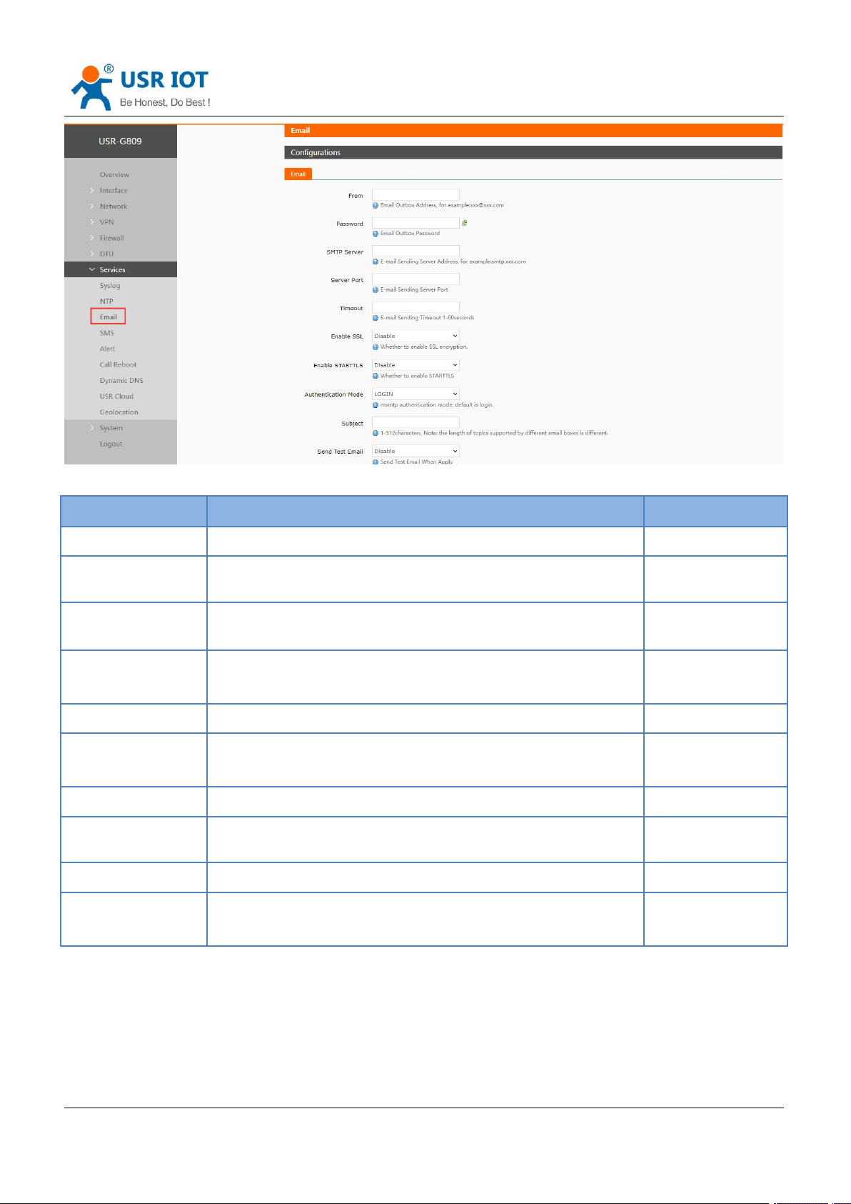
9.3. Email
After connecting to the network, this mailbox will be used as the sender to send a specific alarm email to the
set email address.
Page 79
USR-G809 User Manual Technical Support:
Jinan USR IOT Technology Limited www.pusr.com
79
Item
Description
Default
From
Sender mail of the alarm
None
Password
Sender mail password or the set third party mailbox
authorization code
None
SMTP server
Outgoing mail server. Can check in “Set--Client Settings” of the
mail.
None
Server port
Outgoing mail server port. Can check in “Set--Client Settings” of
the mail.
None
Timeout(Units: s)
Email sending timeout: 1~60s
None
Enable SSL
Whether to enable SSL encryption. Can check in “Set--Client
Settings” of the mail.
Disable
Enable STARTTLS
Whether to enable STARTTLS.
Disable
Authentication
Mode
LOGIN/PLAIN/Custom
LOGIN
Subject
Subject when sending the email.
None
Send test email
Whether to enable sending test email
Disable
h.usriot.com
Note:
1. If fails to send the email with the correct configuration, please check if the authorization code is needed.
The authorization code is a special password used by the third party to log in the mail client.
2. Outlook and Tencent Exmail have been validated for this function.
Page 80
USR-G809 User Manual Technical Support:
Jinan USR IOT Technology Limited www.pusr.com
80
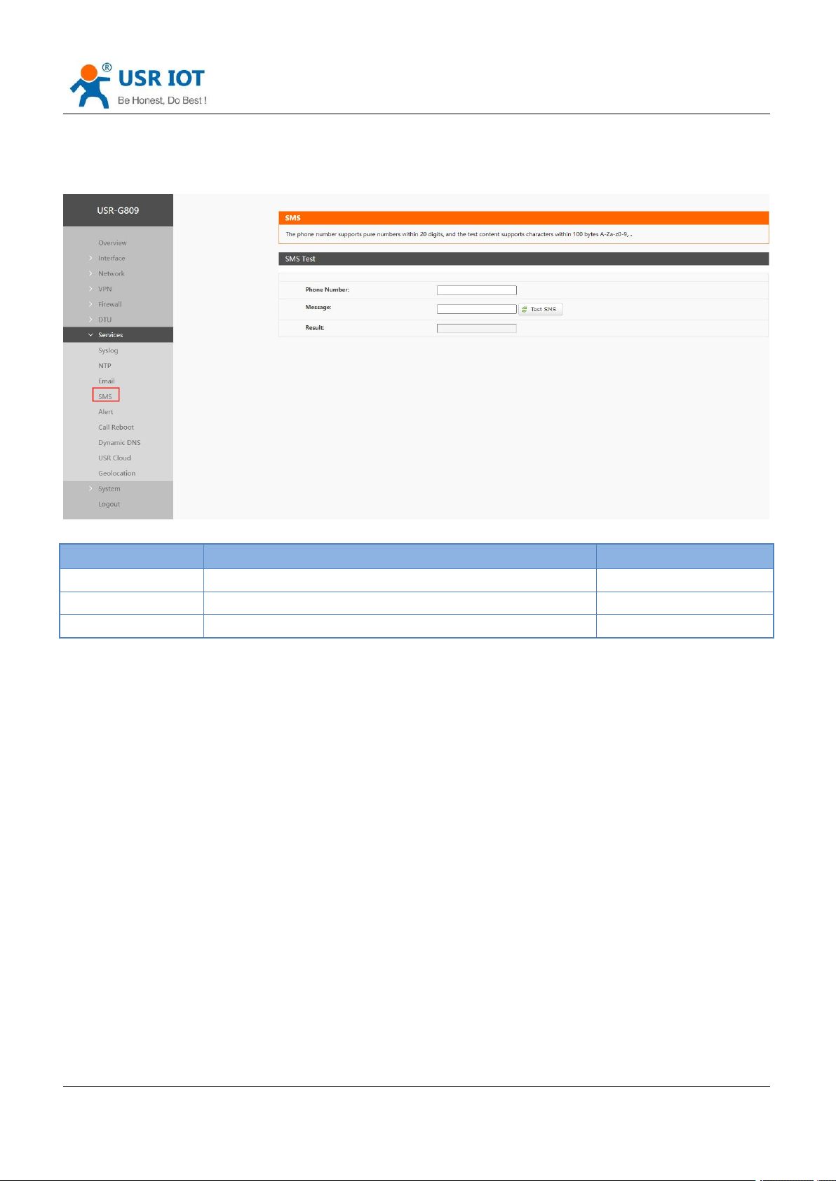
Item
Description
Default
Phone number
Send SMS to this phone number
None
Message
SMS content
None
Result
Success or Fail
-
9.4. SMS
This function is just for SMS test. Please waiting 2~15s after clicking “Test SMS”.
h.usriot.com
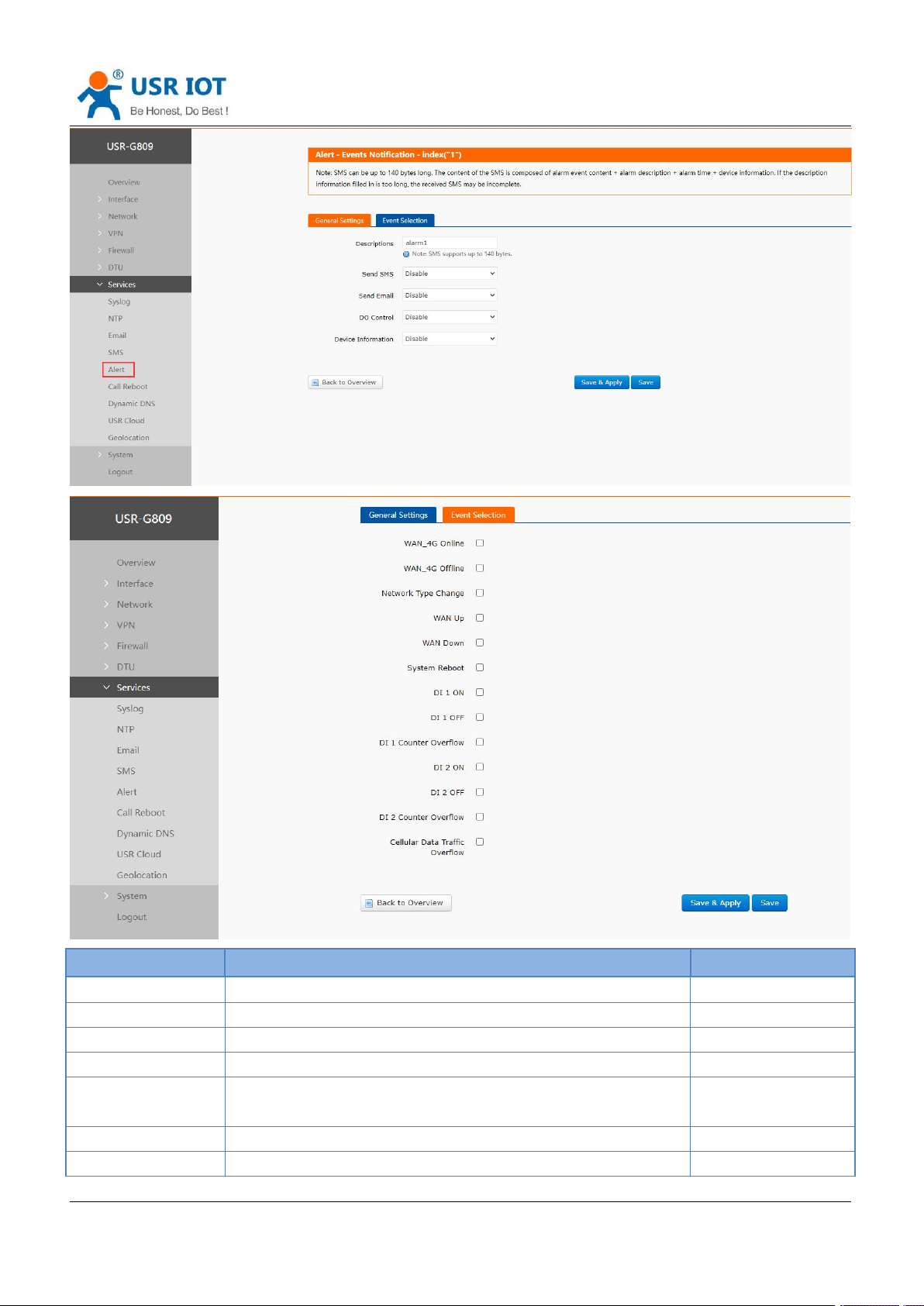
9.5. Alert
G809 supports alerting via SMS, Email and triggering DO, supports carrying device information.
It supports up to 20 alert messages with many different device status.
Page 81
USR-G809 User Manual Technical Support:
Jinan USR IOT Technology Limited www.pusr.com
81
Item
Description
Default
Description
Alarm content
alarmx
Send SMS
Disable/Enable
Disable
Phone number
Phone number to receive the alarm message
None
Send email
Disable/Enable
Disable
Email address
Email address to receive the alarm message, please set the
correct email information in “Email” interface before using it.
None
DO Control
Disable/DO1/DO2
Disable
DO level
Alarm trigger action is "High" or "Low"
High
h.usriot.com
Page 82

USR-G809 User Manual Technical Support:
Jinan USR IOT Technology Limited www.pusr.com
82
Device information
Disable/IMEI/SN/MAC/ICCID
Disable
Event
13 event status
Uncheck
Description:
1. DO control cannot be used simultaneously with DO function in DI/DO. If only enable DO1 in DI/DO,
please select DO2 here.
2. SMS supports up to 140 bytes, including the description, event, time and the message. Do not make the
description too long to avoid receiving incomplete messages.
3. Please ensure the device has connected to the 4G network and the SIM card supports SMS function
before sending SMS.
4. Please ensure the device has connected to the network before sending email.
5. DO alarm is triggered continuously until the next DO is triggered.
6. WAN-4G online: Alarm after successful 4G networking.
7. WAN-4G offline: Alarm after connecting to the 4G network again.
8. Network type change: Alarm when changing the network.
9. WAN up: Alarm when connecting to wired network.
10. WAN down: Alarm when the wired network disconnect.
11. System reboot: Alarm if the device restart without power off.
12. DI 1 ON: Valid when DI1 mode is ON-OFF in “DIDO”, alarm when DI1 is triggered.
13. DI 1 OFF: Valid when DI1 mode is ON-OFF in “DIDO”, alarm when DI1 trigger is canceled.
14. DI1 counter overflow: Valid when DI1 mode is Counter in “DIDO”, alarm when DI1 reaches the threshold
value.
15. DI 2 ON: Valid when DI2 mode is ON-OFF in “DIDO”, alarm when DI2 is triggered.
16. DI 2 OFF: Valid when DI2 mode is ON-OFF in “DIDO”, alarm when DI2 trigger is canceled.
17. DI2 counter overflow: Valid when DI2 mode is Counter in “DIDO”, alarm when DI2 reaches the threshold
value.
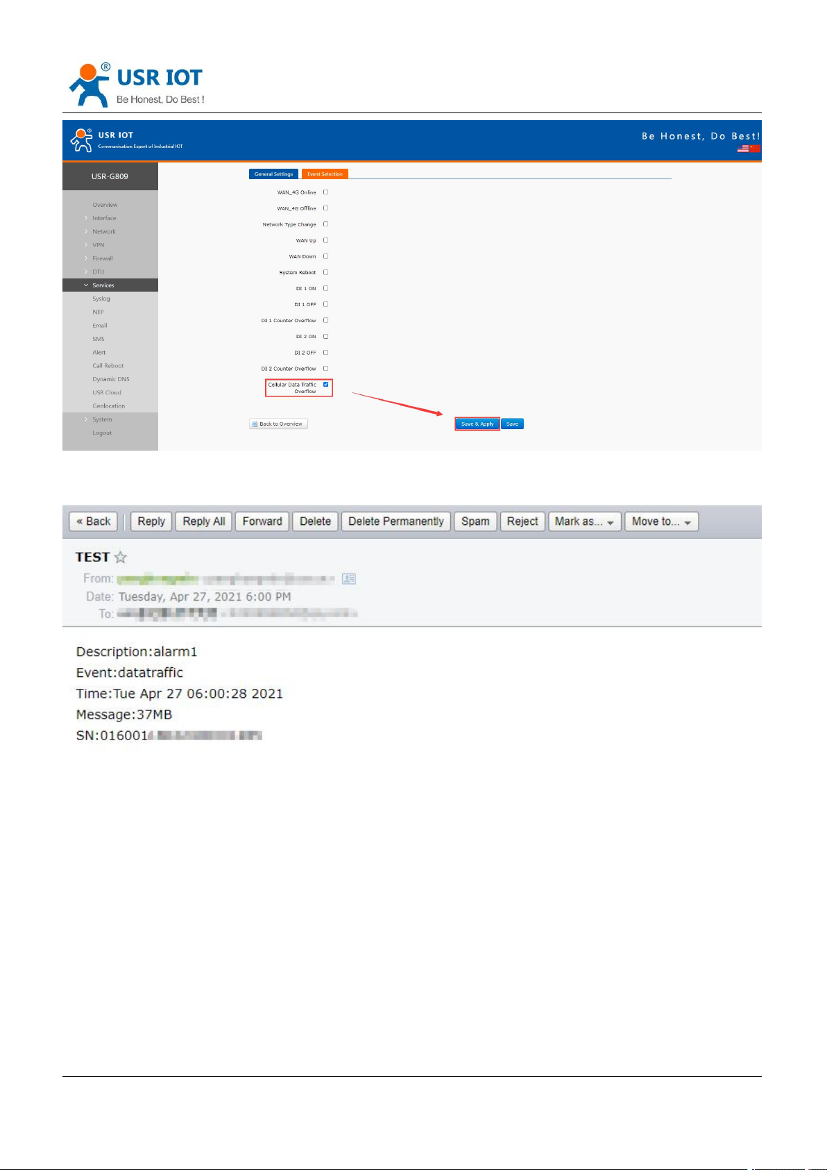
18. Cellular data traffic overflow: This function needs the device to be added in USR Cloud, and enable
“Data traffic control” in “Cellular Network”.
h.usriot.com
9.6. Alert Examples
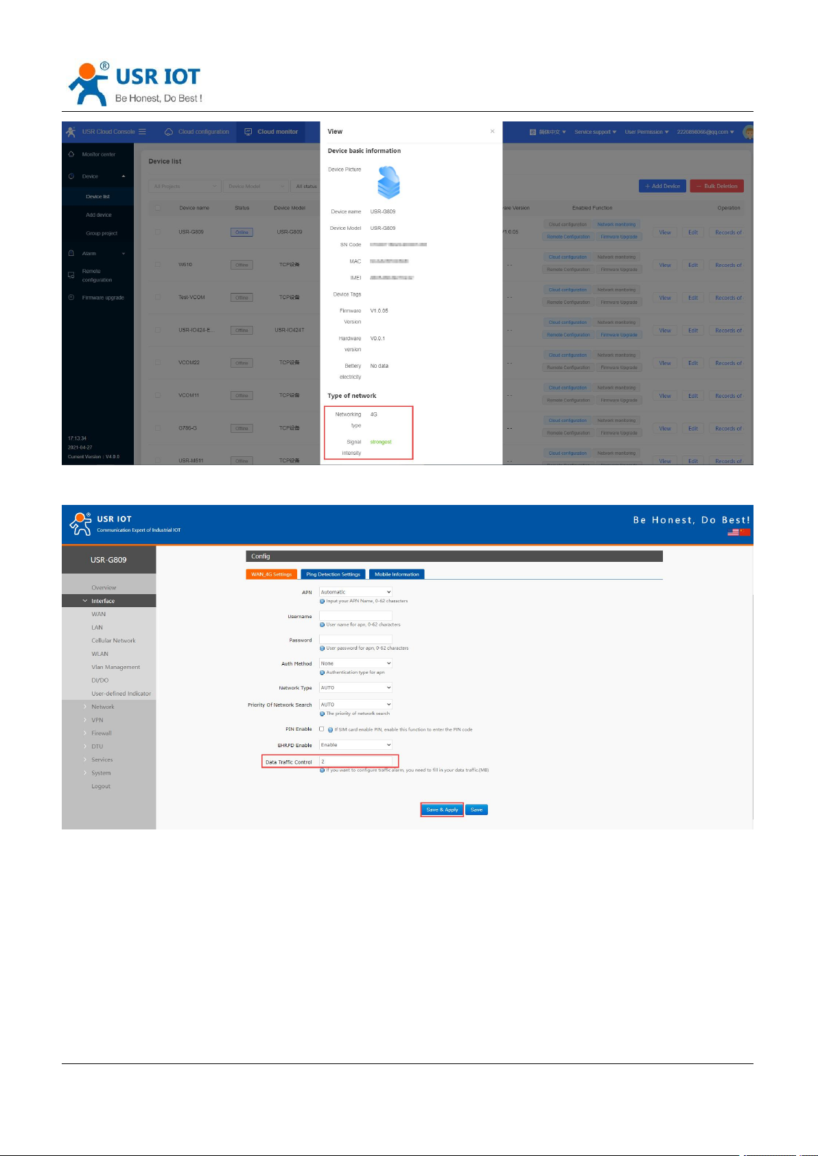
9.6.1.Flow Consumption Alarm via Email
1. Add the device in USR Cloud, please refer to Add device.
Page 83
USR-G809 User Manual Technical Support:
Jinan USR IOT Technology Limited www.pusr.com
83
2. Set the traffic limit to 2MB in a month. Save and apply.
h.usriot.com
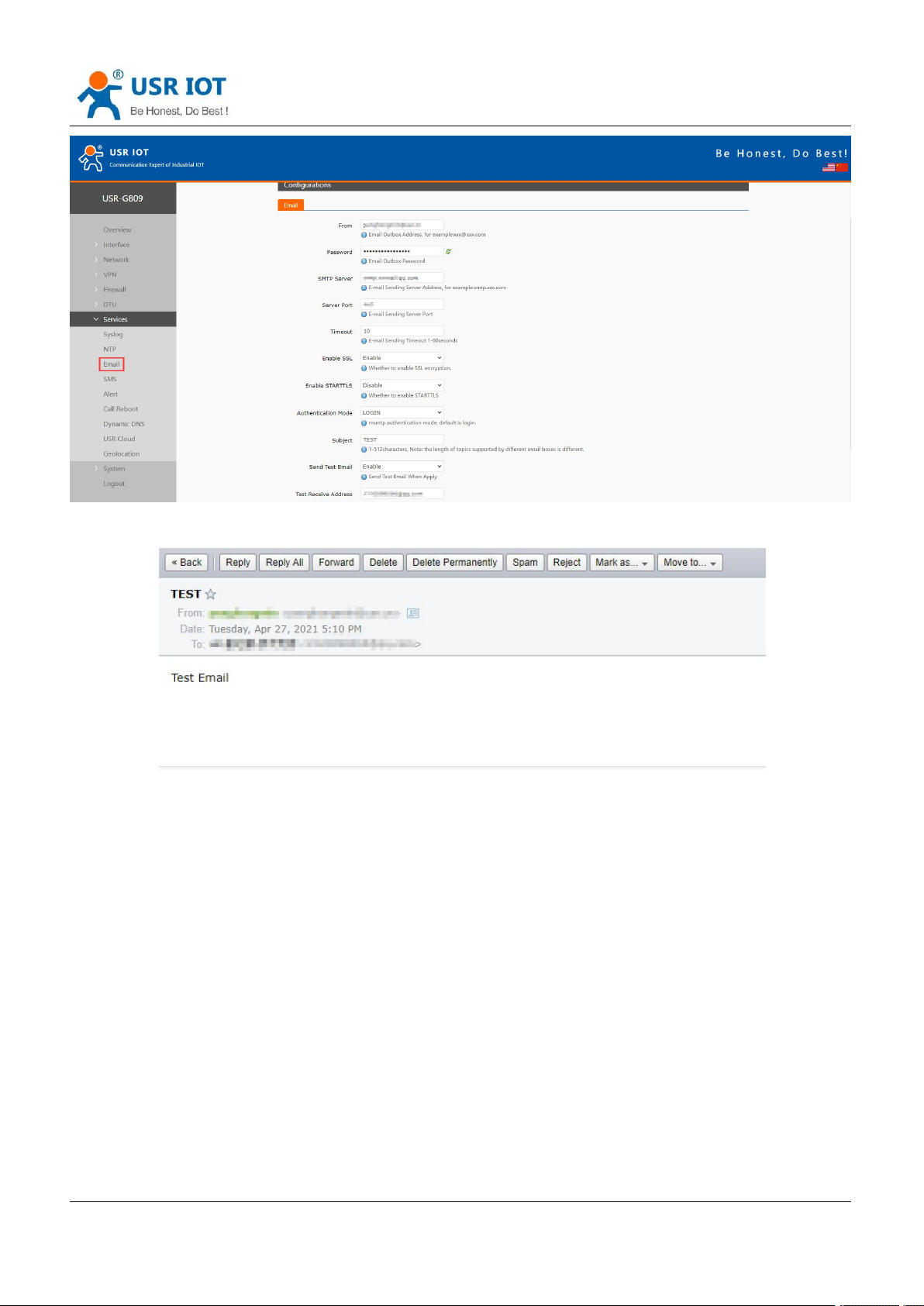
3. Set the mail information in “Email”.
Page 84
USR-G809 User Manual Technical Support:
Jinan USR IOT Technology Limited www.pusr.com
84
When enable “Send test email”, we can receive the test email.
h.usriot.com
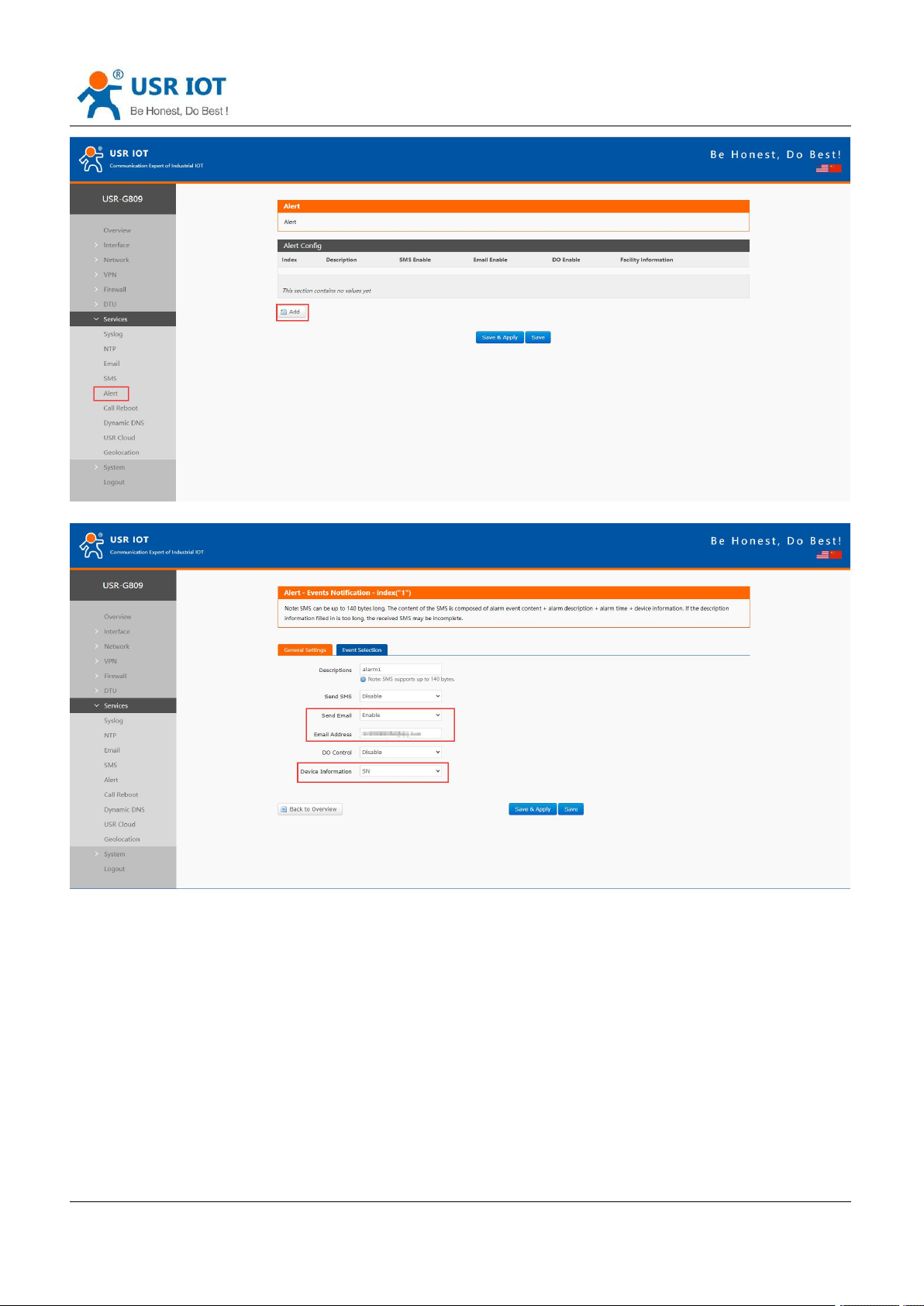
4. Add a alert, enable email alert and carry device SN information. After setting all parameters, click “Save
&Apply”.
Page 85
USR-G809 User Manual Technical Support:
Jinan USR IOT Technology Limited www.pusr.com
85
h.usriot.com
Page 86
USR-G809 User Manual Technical Support:
Jinan USR IOT Technology Limited www.pusr.com
86
h.usriot.com
5. After setting all parameters, restart the device. When the traffic is more than 2M, will receive the alert
email like below:
9.6.2.DI 1 ON SMS Alarm
1. Insert the SIM card that supports SMS function, install the antenna.
2. Please refer to Connecting Hardware for the wiring of DI.
3. Power on the device with the 12V power adaptor.
4. After connecting to the network, the “NET” and “RSSI” indicator lights will be on.
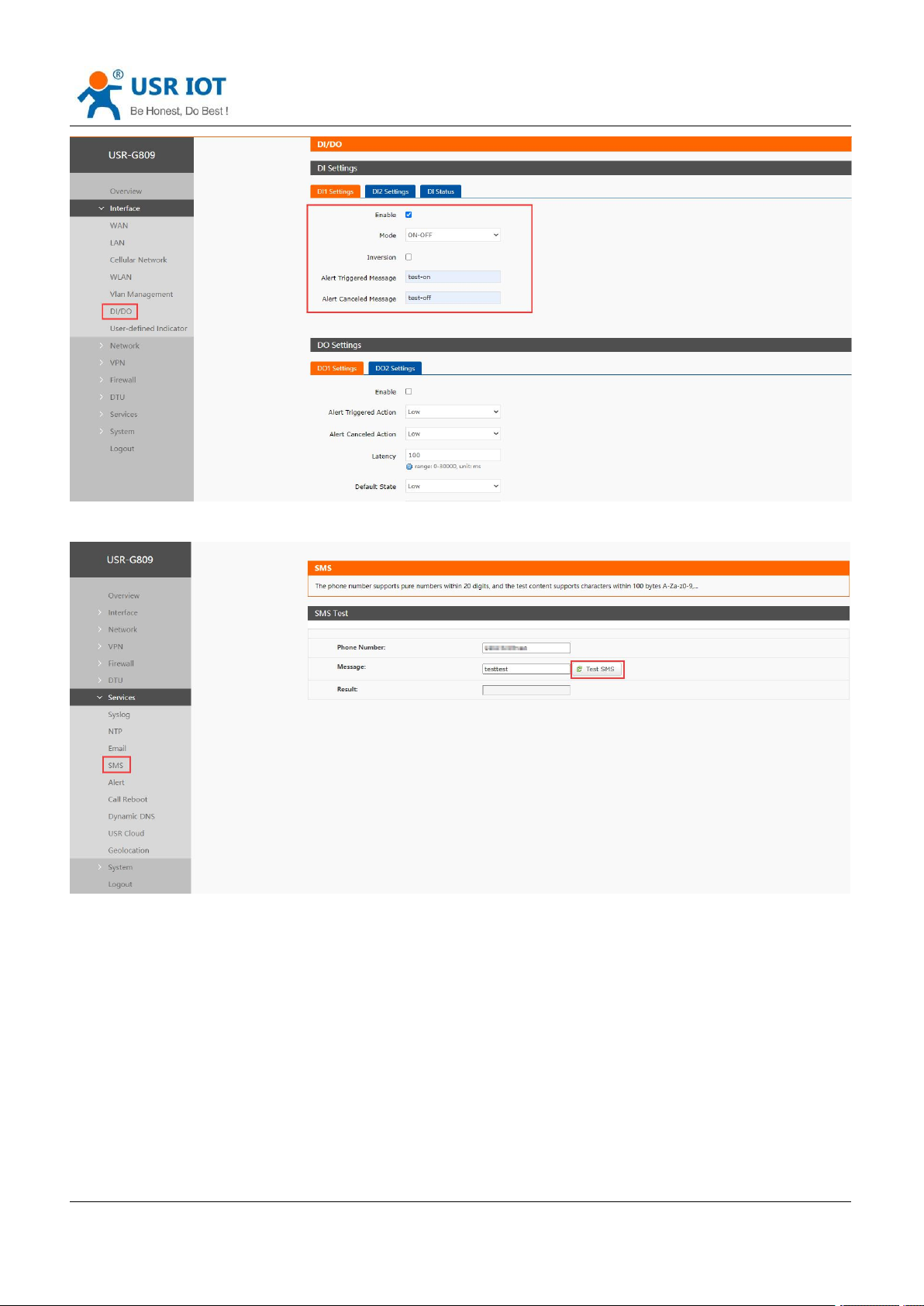
5. Enable DI1, set the mode to “ON-OFF”. Click “Save&Apply”.
Page 87
Jinan USR IOT Technology Limited www.pusr.com
87
6. Send the test SMS.
USR-G809 User Manual Technical Support:
h.usriot.com
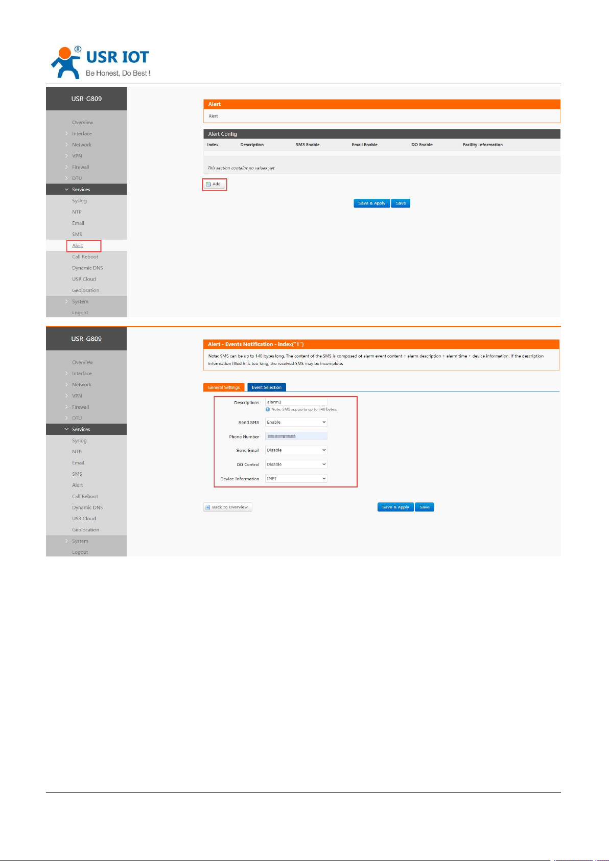
7. Add an alert. Enable SMS alarm, carrying the IMEI of the device.
Page 88
USR-G809 User Manual Technical Support:
Jinan USR IOT Technology Limited www.pusr.com
88
h.usriot.com
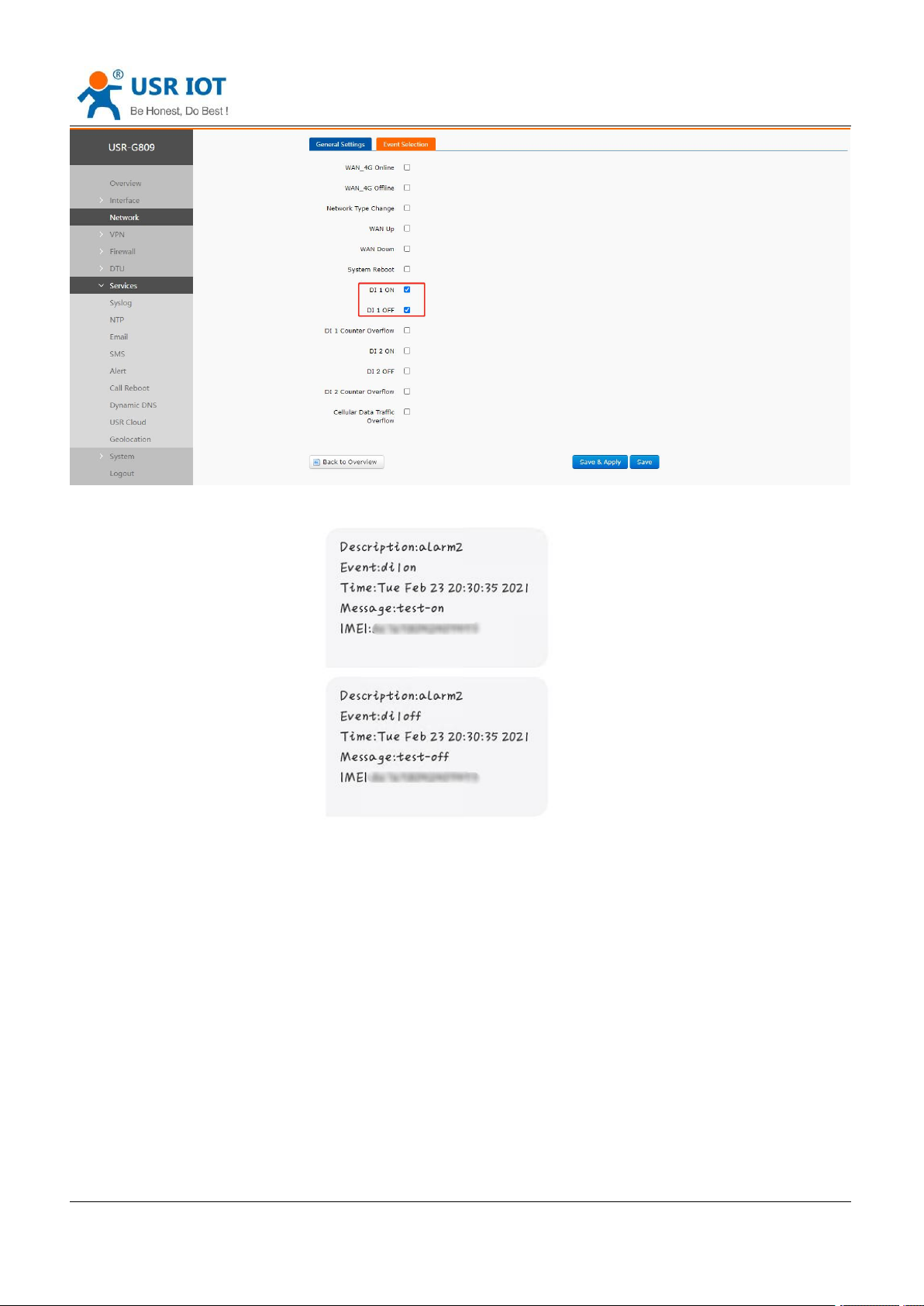
Set the event to DI 1 ON, DI 1 OFF, when DI 1 action, SMS will be sent according to the content set in step 5.
Click “Save&Apply”.
Page 89
USR-G809 User Manual Technical Support:
Jinan USR IOT Technology Limited www.pusr.com
89
h.usriot.com
9.6.3.4G Online/Offline Triggers DO
1. Install the SIM card and antenna.
2. Please refer to Connecting Hardware for the wiring of DO.
3. Power on the device with the 12V power adaptor.
4. After connecting to the network, the “NET” and “RSSI” indicator lights will be on.
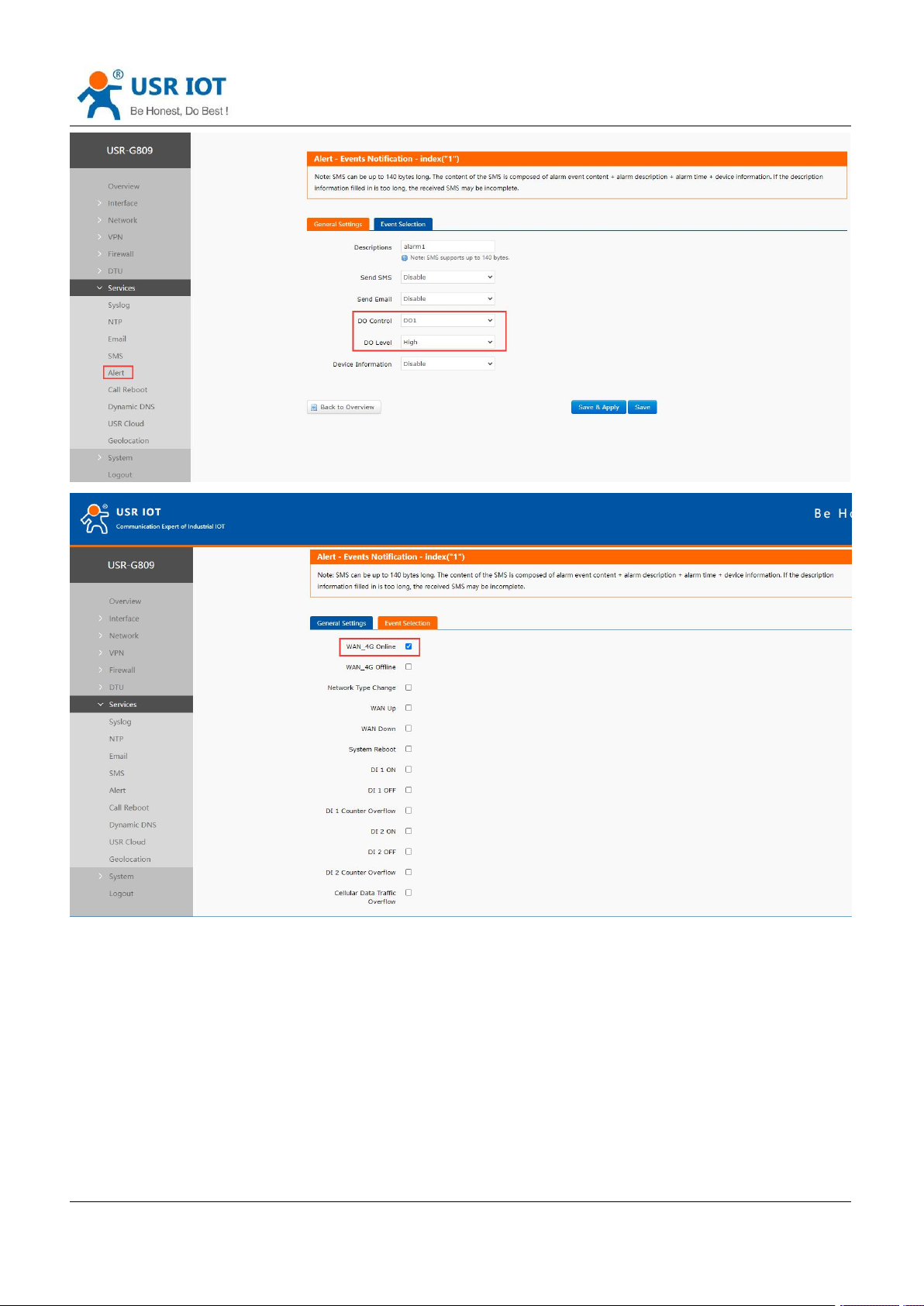
5. Enable “DO Control”, set the output level to “High”. Set the event to “WAN_4G online”.
Page 90
USR-G809 User Manual Technical Support:
Jinan USR IOT Technology Limited www.pusr.com
90
h.usriot.com
Note:
When enable DO1 control, please do not enable DO1 in “DIDO” interface to avoid the conflict.
Please select only one event since the output is DO status.
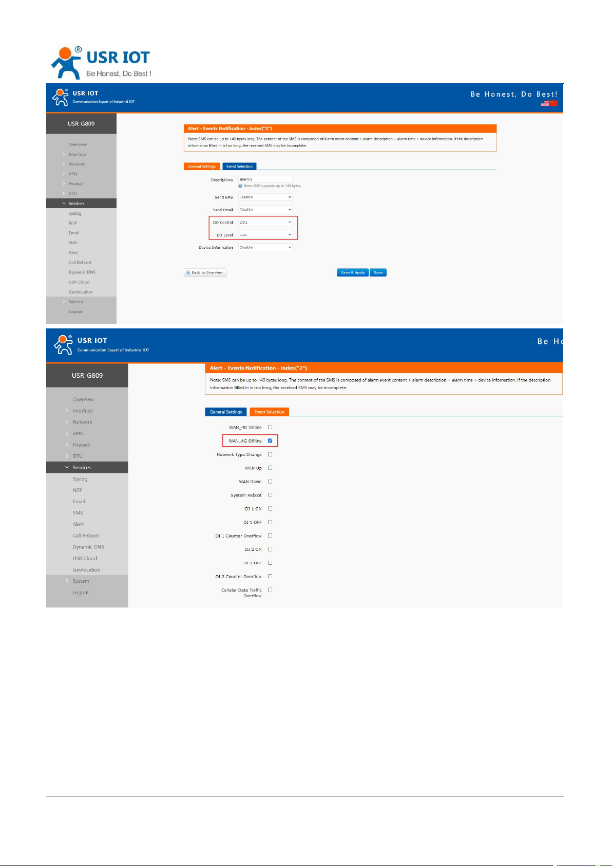
6. Add the second alarm. Set the DO1 output level to Low, the event to WAN_4G offline. After that, click
“Save&Apply”.
Page 91
USR-G809 User Manual Technical Support:
Jinan USR IOT Technology Limited www.pusr.com
91
h.usriot.com
7. When connect to the 4G network successfully, the DO1 will always be set to a high level;
When 4G network is disconnected, the DO1 will always be set to a low level;
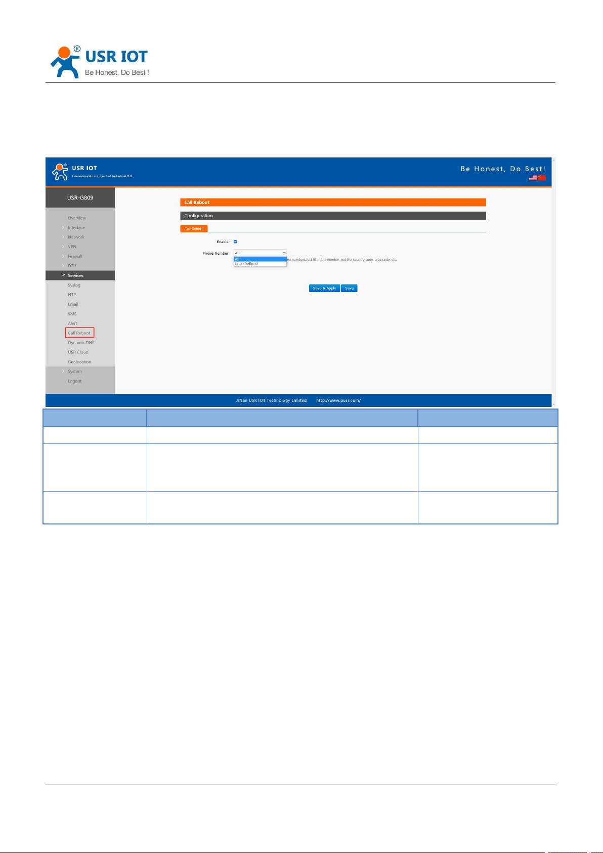
When connecting DO1 to a LED, can control the LED light on and off.
Page 92
USR-G809 User Manual Technical Support:
Jinan USR IOT Technology Limited www.pusr.com
92
Item
Description
Default
Enable
On/Off
Off
Phone number
ALL: Call from any phone number can restart the
device.
User-Defined: Specified phone number, up to 20.
ALL
Custom phone
number
Click “+” to add more numbers
Null
h.usriot.com
9.7. Call Reboot
After installing a SIM card that supports SMS function, when calling the SIM card in device, the device will
restart and send a SMS to the caller.
9.8. Geolocation
9.8.1.GPS Configurations
This feature is not supported in regular versions, optional.
Page 93
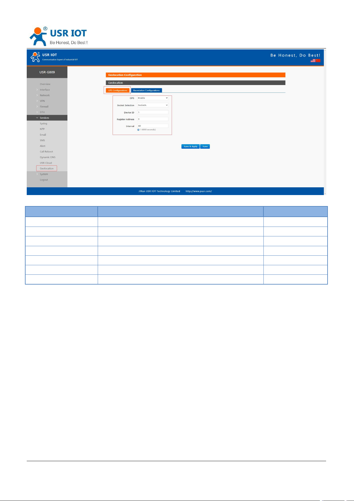
USR-G809 User Manual Technical Support:
Jinan USR IOT Technology Limited www.pusr.com
93
Item
Description
Default
GPS
Enable/Disable
Disable
Socket selection
SocketA or Custom
SocketA
Device ID
Modbus RTU device ID
1
Register address
Modbus RTU register address
0
Interval (s)
Uploading interval, 1-6000s
60
Server custom address
Custom GPS server address, IP or domain Item.
clouddata.usr.cn
Server port
Custom GPS server port
15000
h.usriot.com
GPS frame format:
(When the GPS sensor is abnormal and cannot locate the coordinate information, the latitude and longitude
in the frame are (0.00, 0.00)).
USR-G809 will report the location data in Modbus RTU to the GPS server actively.
Data reported by G809:
01 46 00 00 00 12 24 00 06 00 01 68 90 E7 27 48 C9 40 5D C4 FD 85 AA 56 7E 40 42 01 CC 00 00 00 64 00
00 F2 59 5C 87 13 56 2D 2E
Longitude: 68 90 E7 27 48 C9 40 5D
Latitude: C4 FD 85 AA 56 7E 40 42
10 bytes base station positioning: 01 CC 00 00 00 64 00 00 F2 59
Timestamp: 5C 87 13 56
CRC: 2D 2E
Page 94
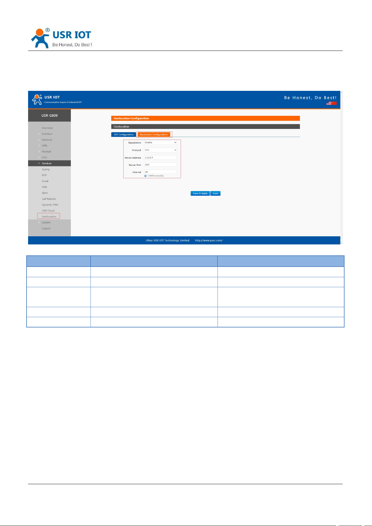
USR-G809 User Manual Technical Support:
Jinan USR IOT Technology Limited www.pusr.com
94
Item
Description
Default
Base station
Enable/Disable
Disable
Protocol
TCP /UDP
TCP
Server address
Specified server address, IP or domain
Item
1.2.3.4
Server port
Specified server port
654
Interval (s)
Reporting interval, 1-6000s
60
h.usriot.com
9.8.2.Base Station Configurations
After enable this function, G809 will send the base station information to the server via the specified protocol
format.
9.9. DDNS
DDNS function allows remote access to the router directly through the domain Item instead of your dynamic
IP address, which changes from time to time.
9.9.1.Supported Services
If you are using the DNS service provider can be found in the "Services" drop-down box, please configure like
below:
Page 95
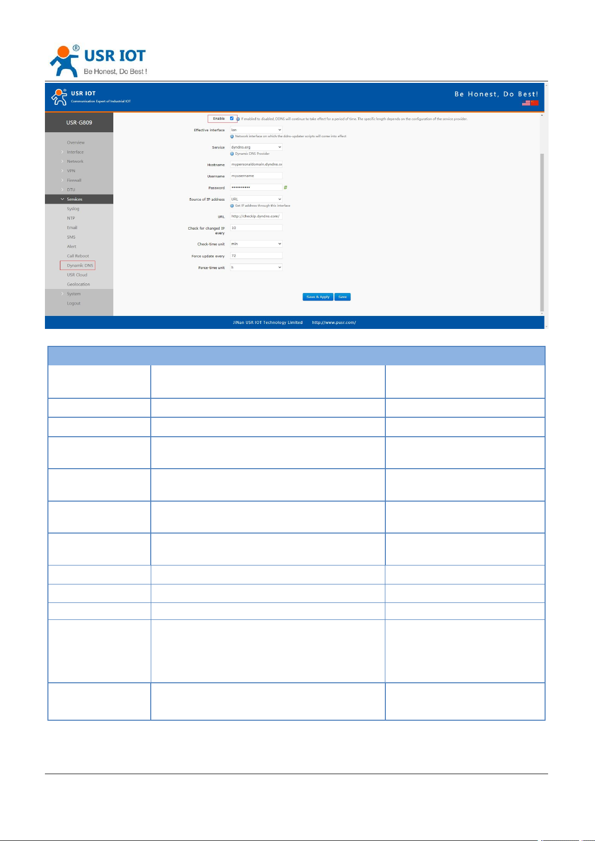
USR-G809 User Manual Technical Support:
Jinan USR IOT Technology Limited www.pusr.com
95
Item
Description
Default
Enable
On/Off
Off
Effective interface
lan/wan_wired/wan_4g
lan
Service
DDNS server address
dyndns.org
Hostname
Enter the hostname provided by the DDNS
server.
mypersonaldomain.dyndns.org
Username
Enter the username provided by the DDNS
server
myusername
Password
Enter the password provided by the DDNS
server
mypassword
Source of IP
address
Network/Interface/URL
URL
Interface
eth0.2/eth1
Eth0.2
URL
Set the IP source URL address
http://checkip.dyndns.com/
Network
wan_wired/wan_4g
wan_wired
Check for changed
IP every/unit
The interval at which IP address changes are
detected. The IP binding of the domain name
may change frequently, and the lower the value,
the more frequent the detection.
10 min
Force update
every/unit
The time interval for forced updates.
72 h
h.usriot.com
Page 96
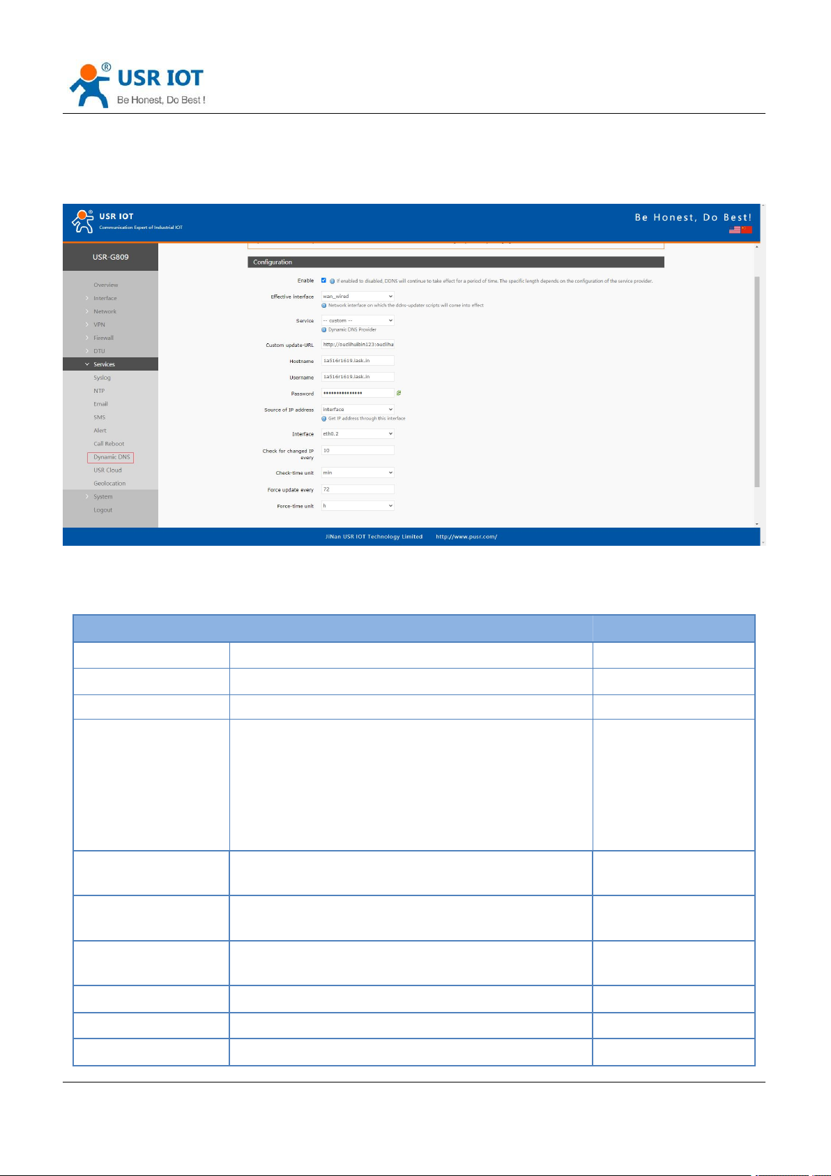
USR-G809 User Manual Technical Support:
Jinan USR IOT Technology Limited www.pusr.com
96
Item
Description
Default
Enable
On/Off
Off
Effective
lan/wan_wired/wan_4g
lan
Service
Custom
---
Custom update-URL
DDNS server address, here we take “ddns.oray.com”
as an example. Please enter with the format of
“http://username:[email protected]/ph/updat
e?hostname=hostname provided by the DDNS
server”
Example:
http://ouclihuibin123:o
uclihuibin1231@ddns.
oray.com/ph/update?h
ostname=1a516r1619.
iask.in
Hostname
Enter the hostname provided by the DDNS server
Example:
1a516r1619.iask.in
Username
Enter the username provided by the DDNS server
Example:
ouclihuibin123
Password
Enter the password provided by the DDNS server
Example:
ouclihuibin123
Source of IP address
Network/Interface/URL
URL
Interface
eth0.2/eth1
Eth0.2
URL
Set the IP source URL address
http://checkip.dyndns.
h.usriot.com
9.9.2.Custom Services
If you are using the DNS service provider can not be found in the "Services" drop-down box, please select
“Custom”, then configure like below:
Here we use “ddns.oray.com” as an example, the hostname is “1a516r1619.iask.in”, username is
“ouclihuibin123”, password “ouclihuibin123”.
Page 97
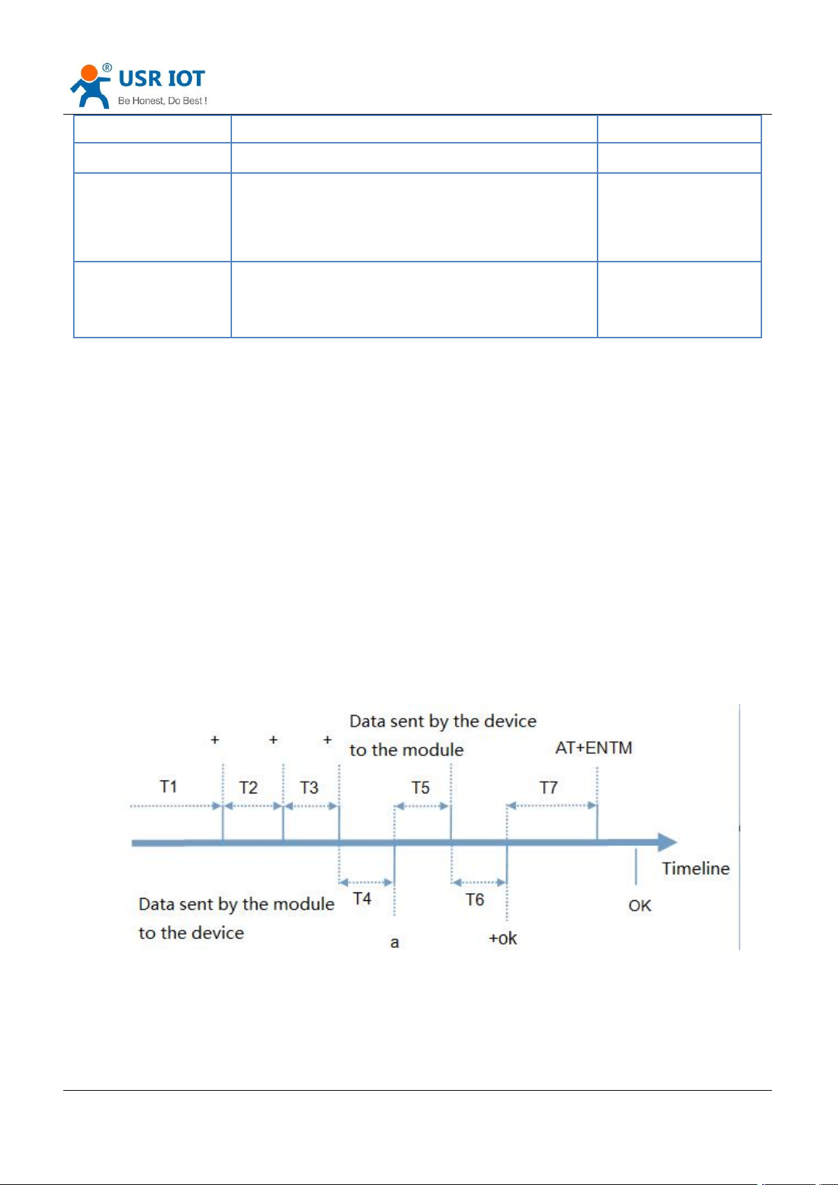
USR-G809 User Manual Technical Support:
Jinan USR IOT Technology Limited www.pusr.com
97
com/
Network
wan_wired/wan_4g
wan_wired
Check for changed IP
every/unit
The interval at which IP address changes are
detected. The IP binding of the domain name may
change frequently, and the lower the value, the more
frequent the detection.
10 min
Force update
every/unit
The time interval for forced updates.
72 h
Note:
After setting all parameters, please restart the device to take the parameters effect.
Dynamic domain names work even if the router is in subnet.
DDNS + port forwarding can realize remote access to the router subnet.
This function requires the router's network to be assigned to a separate public IP.
h.usriot.com
10. AT Commands Settings
10.1. AT Command Mode
When the device works in network transparent mode or HTTP mode, can switch to "AT command mode" by
sending time-specific data by serial port. When the operation is completed in "AT command mode", send
specific commands to return to the previous working mode.
Toggles the timing of command mode:
In the figure above, the horizontal axis is time, data above the time axis is sent by the serial device to G809,
data below the time axis is sent by G809 to the serial port.
Time requirement:
Page 98
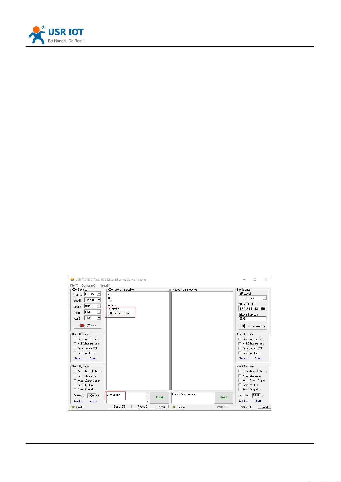
USR-G809 User Manual Technical Support:
Jinan USR IOT Technology Limited www.pusr.com
98
T1 > current serial port packaging interval
T2 < current serial port packaging interval time
T3 < current serial port packaging interval time
T4 = current serial port packaging interval time
T5 < 3 s
T6 = current serial port packaging interval time
The time sequence of switching from transparent mode/HTTP mode to “AT Command mode” :
1. Serial device continuously sends "+++" to the device. After receiving "+++", the device will send an "a" to
the serial device. No data can be sent during a packaging cycle before sending "+++".
2. When the serial device receives “a”, a “a” must be sent to the device within 3 seconds.
3. After receiving 'a', the device returns "+ok" and enter “temporary command mode”.
4. After receiving "+ok", the device has enter "temporary command mode" and now can send AT command
to it.
Time sequence of switching from AT command mode to transparent mode.HTTP mode:
1. Serial device sends "AT+ENTM" to G809.
2. After receiving the command, sends "OK" to the serial device and returns to the previous working mode.
3. After the serial device receives "OK", it knows that the device has returned to its previous working mode.
h.usriot.com
10.2. Serial AT Commands
In transparent mode, do not need to switch to the command mode, we can use “Command password + AT
command” to query and set parameters. It does not need complicated “+++” timing sequence to enter AT
command mode, so as to quickly query or set parameters.
Before sending, enter AT command mode, query the command password firstly. It defaults to “test.cn#”.
Restart the device after setting.
Send “test.cn#AT+MAC” from the serial port (there is an “Enter” after the command), then can receive the
response from the device:
Page 99
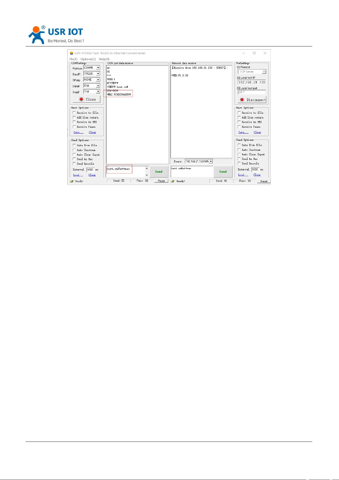
USR-G809 User Manual Technical Support:
Jinan USR IOT Technology Limited www.pusr.com
99
h.usriot.com
10.3. Network AT Commands
Network AT command refers to set and query parameters by sending “Command password + AT command”
through the network when working in transparent mode. Here we query the firmware version of the device,
there is an “Enter” after the command.
Page 100
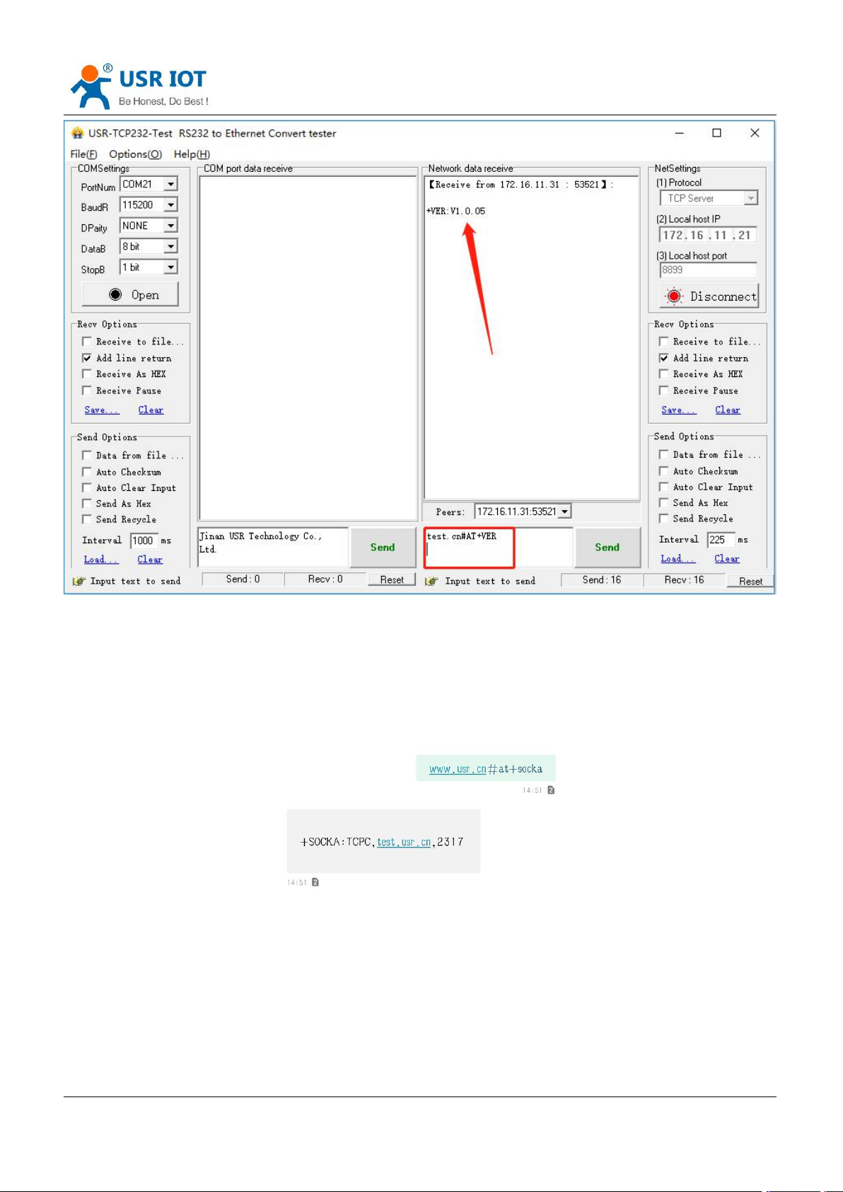
USR-G809 User Manual Technical Support:
Jinan USR IOT Technology Limited www.pusr.com
100
h.usriot.com
10.4. SMS AT Commands
In transparent mode, we can also send SMS to query and set the device parameters. Here we send
“Command password+AT Commands” to query the socket connection status.
For detailed AT Commands, please refer to AT Command set.
 Loading...