

Page 1
Technical Support: h.usriot.com
1
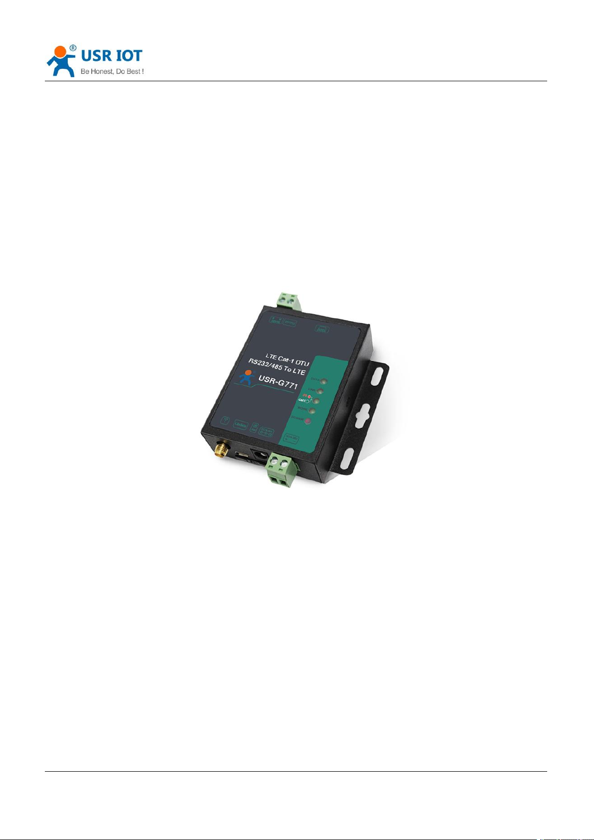
USR-G771-E User Manual
Document version: V1.0.5
Page 2

USR-G771-E User Manual Technical Support: h.usriot.com
Jinan USR IOT Technology Limited www.pusr.com
2
1. Introduction ............................................................................................................................................................. 3
1.1. Overview ...................................................................................................................................................... 3
1.2. Features ....................................................................................................................................................... 3
2. Get Started ..............................................................................................................................................................4
2.1. Specification .................................................................................................................................................4
2.2. Hardware ......................................................................................................................................................5
2.2.1. Dimensions ........................................................................................................................................5
2.2.2. Indicators ........................................................................................................................................... 6
2.2.3. Connecting Hardware ........................................................................................................................6
3. Utility Configuration .................................................................................................................................................7
3.1. Download the Utility ..................................................................................................................................... 7
3.2. Starting the Configuration Utility .................................................................................................................. 7
4. Serial Port ............................................................................................................................................................... 9
4.1. Basic Parameters .........................................................................................................................................9
4.2. Frame forming mechanism ........................................................................................................................ 10
4.2.1. Time Trigger .................................................................................................................................... 10
4.2.2. Length trigger .................................................................................................................................. 10
5. Selecting an Operating Mode ............................................................................................................................... 11
5.1. Transparent Mode ......................................................................................................................................11
5.2. HTTPD Client Mode ................................................................................................................................... 14
5.3. SMS Mode ..................................................................................................................................................16
5.4. MQTT Mode ...............................................................................................................................................18
5.4.1. Generic MQTT .................................................................................................................................19
5.4.2. Subscribe/Public Topics .................................................................................................................. 21
5.4.3. AWS IoT Service ............................................................................................................................. 22
6. General Function .................................................................................................................................................. 31
6.1. Identity Package .........................................................................................................................................31
6.2. Heartbeat Package .................................................................................................................................... 33
6.3. Socket Distribution Protocol .......................................................................................................................34
6.4. Backup Socket ........................................................................................................................................... 35
6.5. SSL/TLS Encryption ...................................................................................................................................36
6.6. Security ...................................................................................................................................................... 37
6.7. NTP ............................................................................................................................................................ 39
6.8. FTP Upgrade ..............................................................................................................................................40
6.9. Base Station Geolocation ...........................................................................................................................40
6.10. Firmware Upgrade ................................................................................................................................... 40
6.11. Restore to Factory Default Settings .........................................................................................................41
6.12. Timeout Restart ........................................................................................................................................42
7. AT Commands ......................................................................................................................................................42
7.1. AT Command Settings ...............................................................................................................................42
7.2. Serial AT Commands .................................................................................................................................43
7.3. Network AT Commands .............................................................................................................................43
7.4. SMS AT Commands .................................................................................................................................. 44
Page 3
USR-G771-E User Manual Technical Support: h.usriot.com
Jinan USR IOT Technology Limited www.pusr.com
3
1. Introduction
1.1. Overview
USR-G771-E is a LTE CAT 1 communication modem, which supports LTE and GSM, covers the mainstream
frequency bands of European operators. It has perfect software function, supports TCP/UDP transparent
transmission, SMS transmission, HTTPD Client mode and AT command configuration. In addition, it is simple
to configure, has high reliability and built-in hardware watchdog, supports FOTA upgrading.
USR-G771-E supplies a wide voltage range power through terminal and DC interface, RS232 and RS485
standard interfaces, meets the needs of different application scenarios.
1.2. Features
Equipped with CAT-1 network, 10Mbps download rate, 5Mbps upload rate, meeting 80% of the data
transmission application scenarios
Low latency in milliseconds
Multiple modes, supports LTE CAT 1 and GPRS
Wide coverage, high stability based on existing 4G network
Supports TCP/UDP, HTTPD and SMS transparent transmission
Each socket supports buffering 20 packets of serial port data, each packet is up to 4K
Supports parameter configuration via network, serial and SMS AT command
Supports base station geolocation and NTP function
Support 9~36V wide voltage supply
Page 4

USR-G771-E User Manual Technical Support: h.usriot.com
Jinan USR IOT Technology Limited www.pusr.com
4
Parameters
Description
Basic Parameters
USR-G771-E
Supports B1/B3/B7/B8/B20
Power
DC 9V~36V
Operating current
Average: 21mA-50mA, maximum: 54mA (12V)
Indicators
POWER: Power indicator, always on after normal power supply.
WORK: Working status indicator, flashes every second.
NET: Network status indicator, green means 4G, red means 2G.
LINK: Socket A connection status indicator, always on after connecting.
DATA: Data transmission indicator, on when there is data transmission.
SIM/USIM
3V/1.8V SIM slot, 2FF
USB interface
Slave, MicroUSB, USB 2.0 High speed
UART interface
RS232 and RS485, baud rate 1200~230400 bps.
Antenna interface
SMA female cellular antenna connector
Environmental
Dimensions(mm)
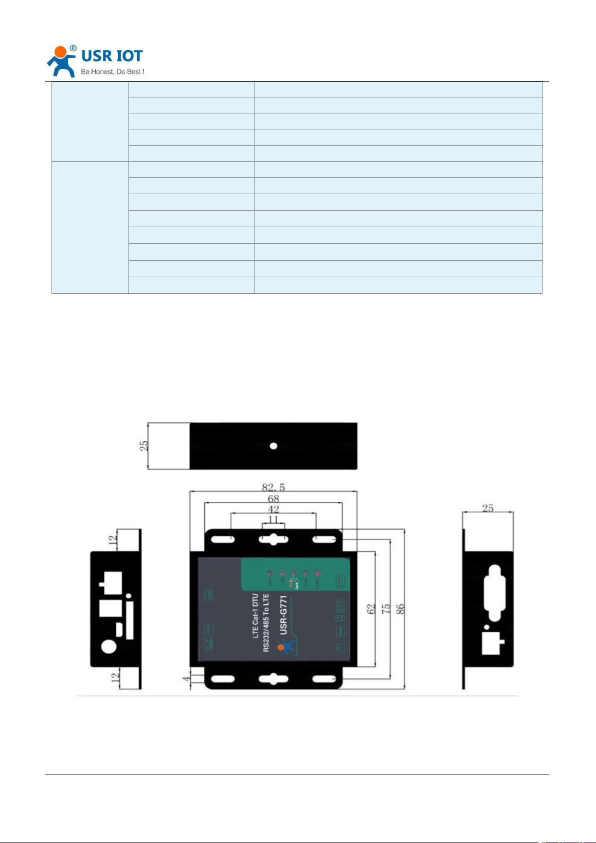
82.6 × 86 × 25
Weight(g)
<110g
Temperature
Operating temperature
-30℃~ +75℃
Storage temperature
-40℃~ +90℃
Humidity
Operating humidity
5%~95% (non-condensing)
Transmission
speed
LTE FDD Rel.13
10MbpsDL/5Mbps UL
GPRS
85.6KbpsDL/85.6Kbps UL(multi-slot class 12)
Bands
LTE FDD
B1/B3/B7/B8/B20
GSM
900/1800MHz
TX Power
FDD:B1/3/7/8/20/28
23dBm±2dB
GSM:900MHz
33dBm±2dB
GSM:1800MHz
30dBm±2dB
Rx Sensitivity
GSM:900MHz
-109.5dBm
GSM:1800MHz
-108dBm
FDD:B1/3/20
-98dBm
FDD:B7
-97.5dBm
FDD:B8/B28
-98.5dBm
Multiple indicator lights, convenient and accurate to check the device status
Industrial grade, hardware watchdog, high reliability
2. Get Started
2.1. Specification
Page 5
Jinan USR IOT Technology Limited www.pusr.com
5
Software
Operating mode
TCP/UDP/HTTPD/SMS transparent transmission, CMD mode
Configuration command
AT+command
Network protocol
TCP/UDP/DNS/FTP/HTTP/IPV4/IPV6
Socket number
4
User configuration
Serial/Network/SMS AT command
Features
Socket distribution protocol
Support
Heartbeat package
Support ICCID/IMEI/SN/User-defined/LBS
Identity package
Support ICCID/IMEI/SN/User-defined/CLOUD
FOTA self upgrade
Support
Backup socket
Support
Base station geolocation
Support
FTP upgrade
Support
NTP
Support
2.2. Hardware
USR-G771-E User Manual Technical Support: h.usriot.com
2.2.1.Dimensions
Page 6
USR-G771-E User Manual Technical Support: h.usriot.com
Jinan USR IOT Technology Limited www.pusr.com
6
Indicator
Function
Status
POWER
Power indicator
Always on after normal power
supply.
WORK
Working status indicator.
Flashes every second.
NET
Network status indicator
Green means 4G network, red
means 2G network.
LINKA
Socket A connection status indicator
Always on after socket A is
connected
DATA
Data transmission indicator
On when there is data
transmission
USR-G771-E
Antenna
Power adapter
Female to female
adaptor
2.2.2.Indicators
There are five indicators on USR-G771-E, PWR, WORK, NET, LINKA, DATA.
2.2.3.Connecting Hardware
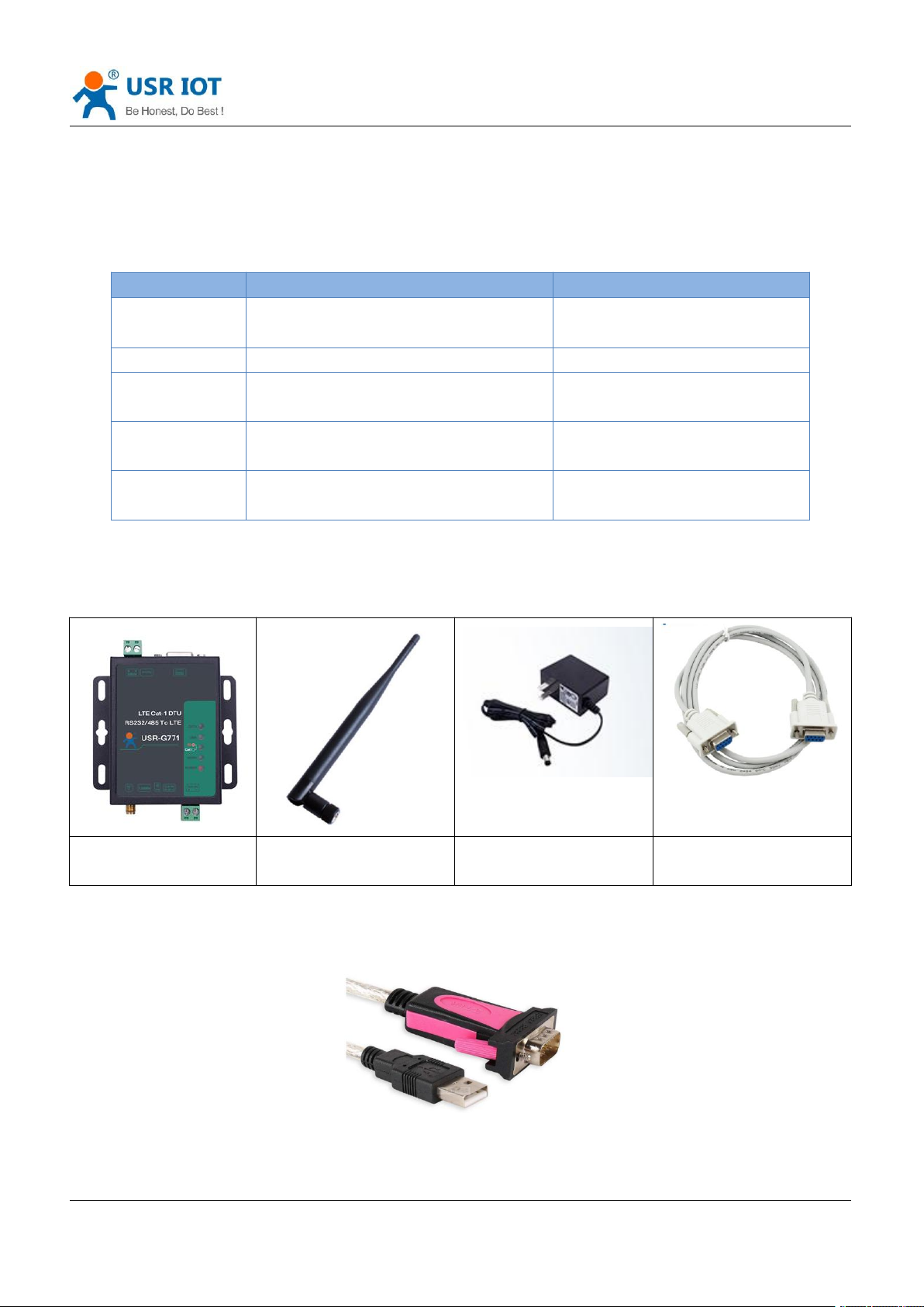
If you have purchased, there will be the following accessories:
Required additional equipment:
RS232 serial to USB cable
Page 7

USR-G771-E User Manual Technical Support: h.usriot.com
Jinan USR IOT Technology Limited www.pusr.com
7
PC
1. Installing SIM card and antenna:
Press the yellow button and the SIM card slot will pop up. Then Install the antenna.
2. Serial Connecting:
RS232: Using the standard RS232 to USB cable, connect the RS232 male connector into the RS232 port
on the G771-E. Connect the USB connector (other end of the cable) into the PC.
RS485: Connect pin A of the RS485 interface of the G771-E to pin A of the RS485 to USB adaptor, pin B of
G771-E to pin B of the adaptor.
3. Power Supply:
Connect 9-36V DC power adapter to power G771-E. Then “POWER” indicator will always on and the
“WORK” indicator will flash.
3. Utility Configuration
3.1. Download the Utility
Please download the utility in this link:
https://www.pusr.com/products/RS232/RS485-serial-to-Cat-1-771.html
3.2. Starting the Configuration Utility
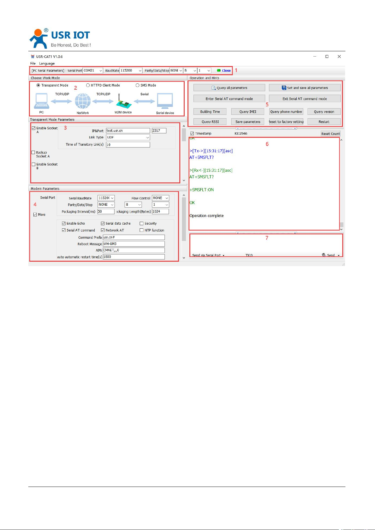
USR-G771-E utility is shown as following:
Page 8
USR-G771-E User Manual Technical Support: h.usriot.com
Jinan USR IOT Technology Limited www.pusr.com
8
Description:
1. In PC serial parameter setting area, it is necessary to set the serial parameters consistent with the serial
device, otherwise they cannot communicate with each other.
2. Working mode selection area, select the work mode of the modem.
3. In the parameter setting area of characteristic functions, set parameters related to modem's featured
functions.
4. Modem parameter area, setup some basic global parameters.
5. Common command button, click to send the self-input command.
6. Data receiving and display area, displaying the data sent and received.
7. Data sending area, input the data and click Send.
Page 9
Jinan USR IOT Technology Limited www.pusr.com
9
4. Serial Port
Item
Parameter
Baud rate
1200~230400bps
Data bit
8
Stop bit
1,2
Check bit
NONE
EVEN
ODD
4.1. Basic Parameters
USR-G771-E User Manual Technical Support: h.usriot.com
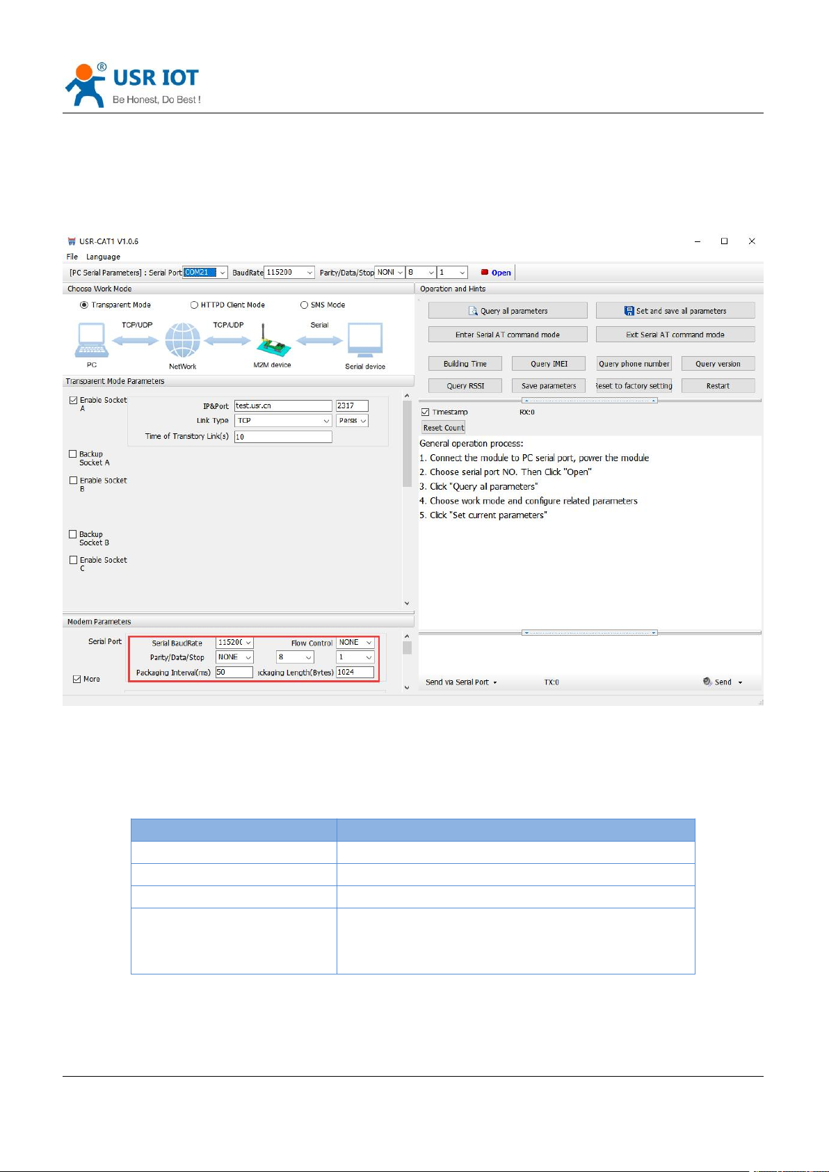
Serial parameters of USR-G771-E must be consistent with the parameters of the serial device. Serial port
parameters include basic parameters and framing parameters.
Page 10
USR-G771-E User Manual Technical Support: h.usriot.com
Jinan USR IOT Technology Limited www.pusr.com
10
4.2. Frame forming mechanism
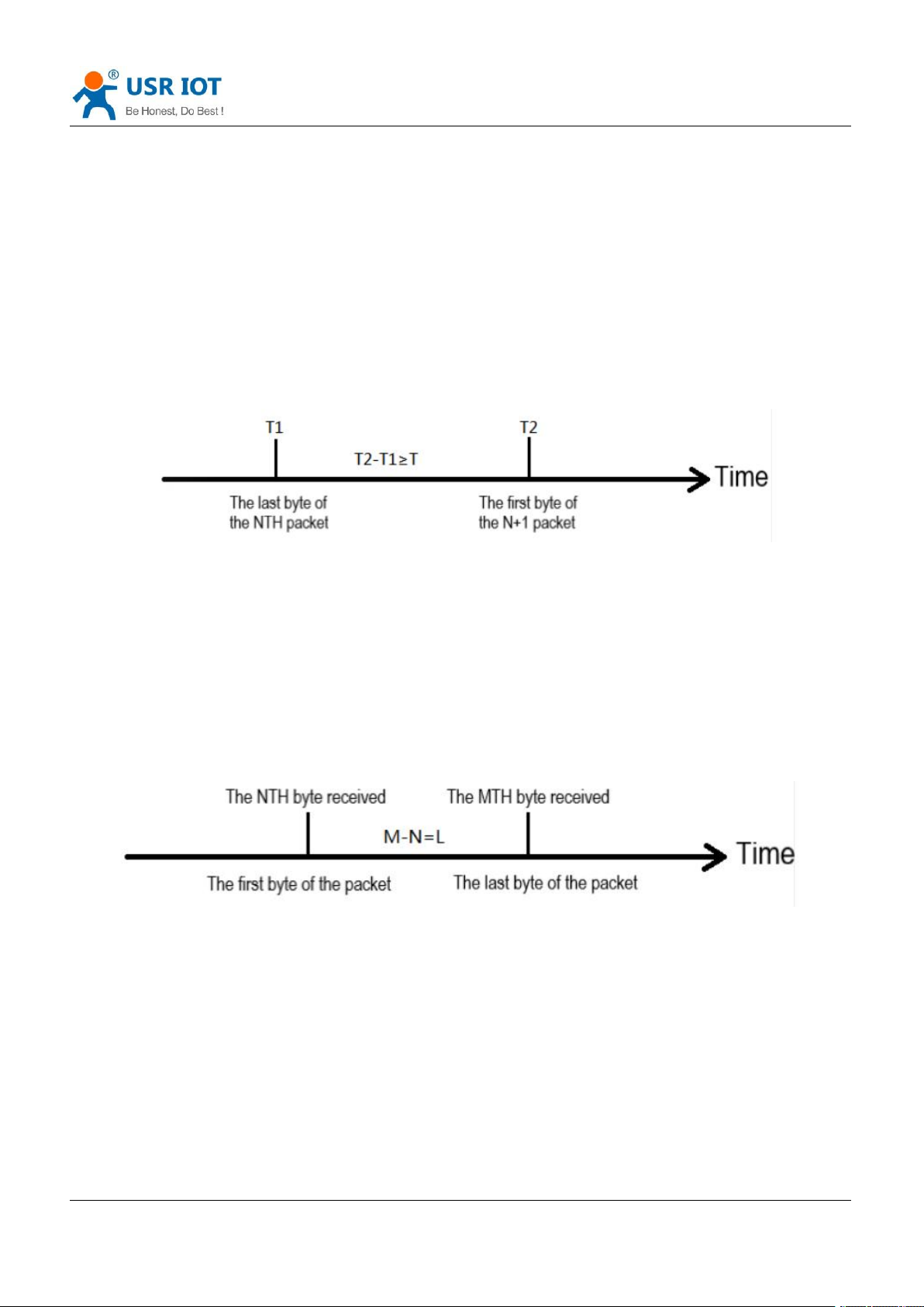
4.2.1.Time Trigger
When G771-E receives data from the UART, it continuously checks the interval of two adjacent bytes. If the
interval time is greater or equal to a certain "time threshold", then a frame is considered finished, otherwise
the data is received until greater or equal to the packet length byte set. This frame is sent to the network as a
TCP or UDP packet. The "time threshold" here is the time between packages. The range of settable is
10ms~500ms. Factory default: 50ms.
This parameter can be set by AT command, AT+UARTFT=<time>.
Note: T is the packing interval time.
4.2.2.Length trigger
When G771-E receives data from the UART, it constantly checks the number of bytes received. If the number
of bytes received is equal to a certain "length threshold", a frame is considered to have ended, otherwise the
packaging time is waiting for the end. This frame is sent to the network as a TCP or UDP packet. The "length
threshold" here is the package length. The settable range is 5~4096. Factory defaults to 1024.
This parameter can be set by AT command, AT+UARTFL=<length>.
Note: L is the packaging length.
Page 11
USR-G771-E User Manual Technical Support: h.usriot.com
Jinan USR IOT Technology Limited www.pusr.com
11
5. Selecting an Operating Mode
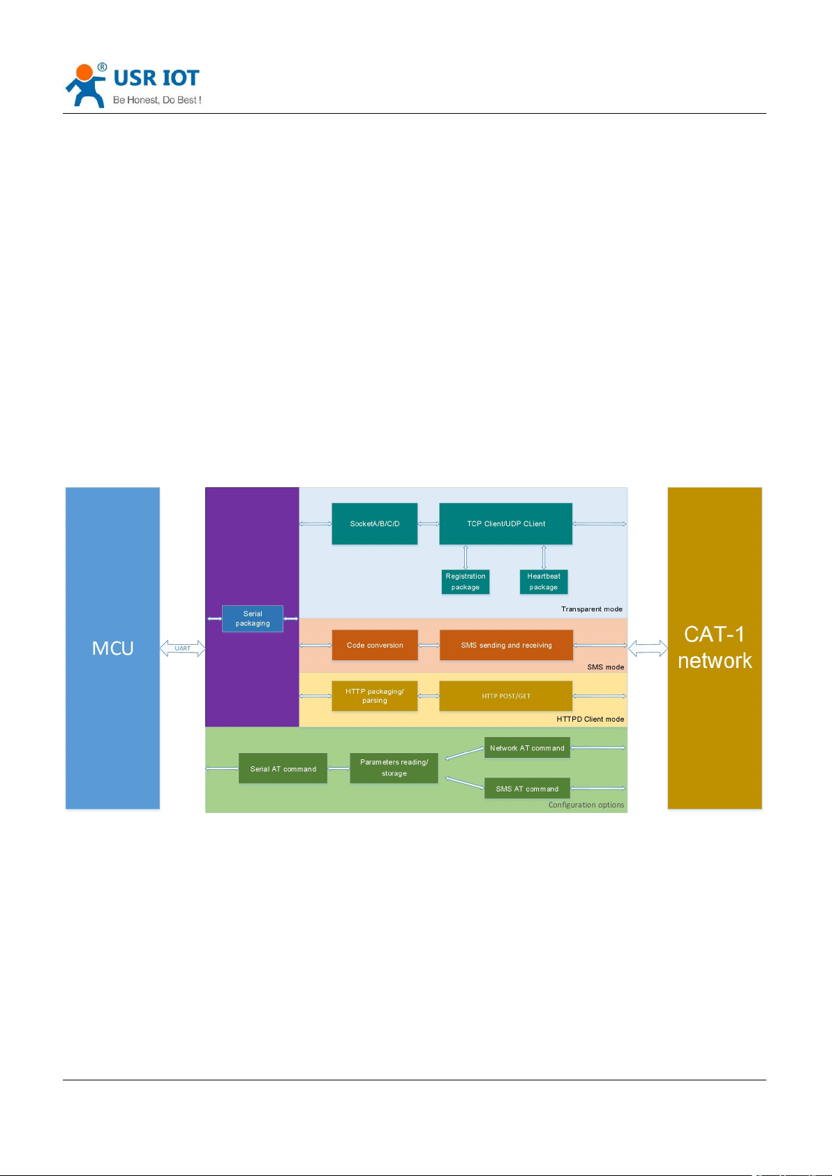
USR-G771-E has three operating modes: transparent mode, HTTPD Client mode and SMS mode.
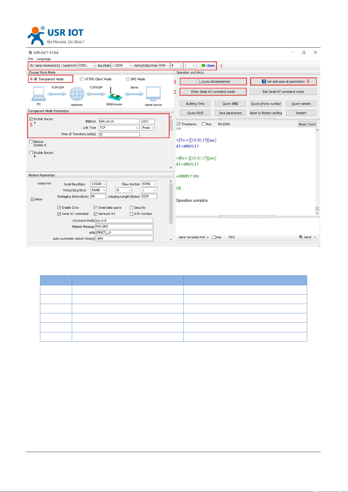
5.1. Transparent Mode
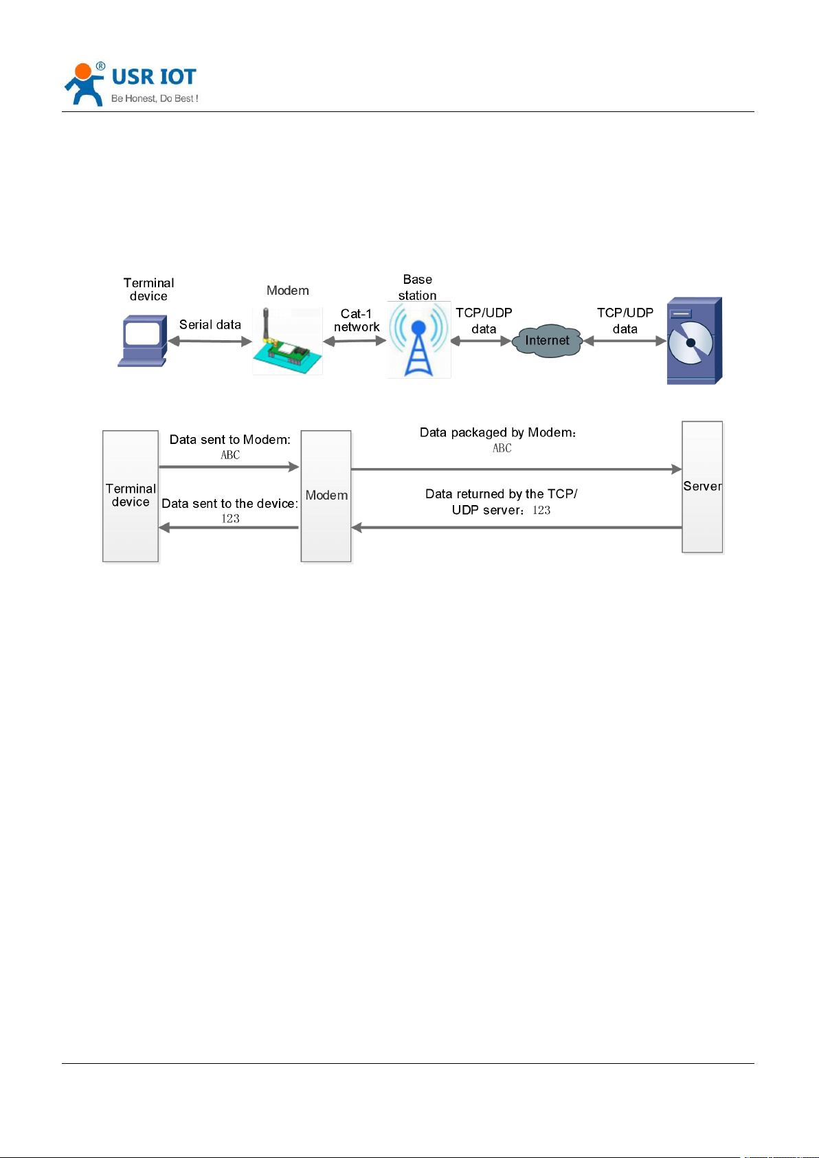
In this mode, users do not need to pay attention to the data conversion process, can realize the bidirectional
data transparent transmission between serial devices and network servers.
G771-E supports 4 socket connections, Socket A, Socket B, socket C and socket D, which are independent with
each other. Each socket supports TCP Client and UDP Client.
Set parameters by the utility:
Page 12
USR-G771-E User Manual Technical Support: h.usriot.com
Jinan USR IOT Technology Limited www.pusr.com
12
Command
Operation
1
+++a
Enter serial AT command mode
2
AT+WKMOD=NET
Set the work mode to Transparent mode
3
AT+SOCKAEN=ON
Enable Socket A
4
AT+SOCKASL=LONG
Set Socket A to persistent link
5
AT+SOCKA=TCP,test.usr.cn,2317
Set the remote IP and port of Socket A
6
AT+S
Save all parameters and restart
Set by AT command:
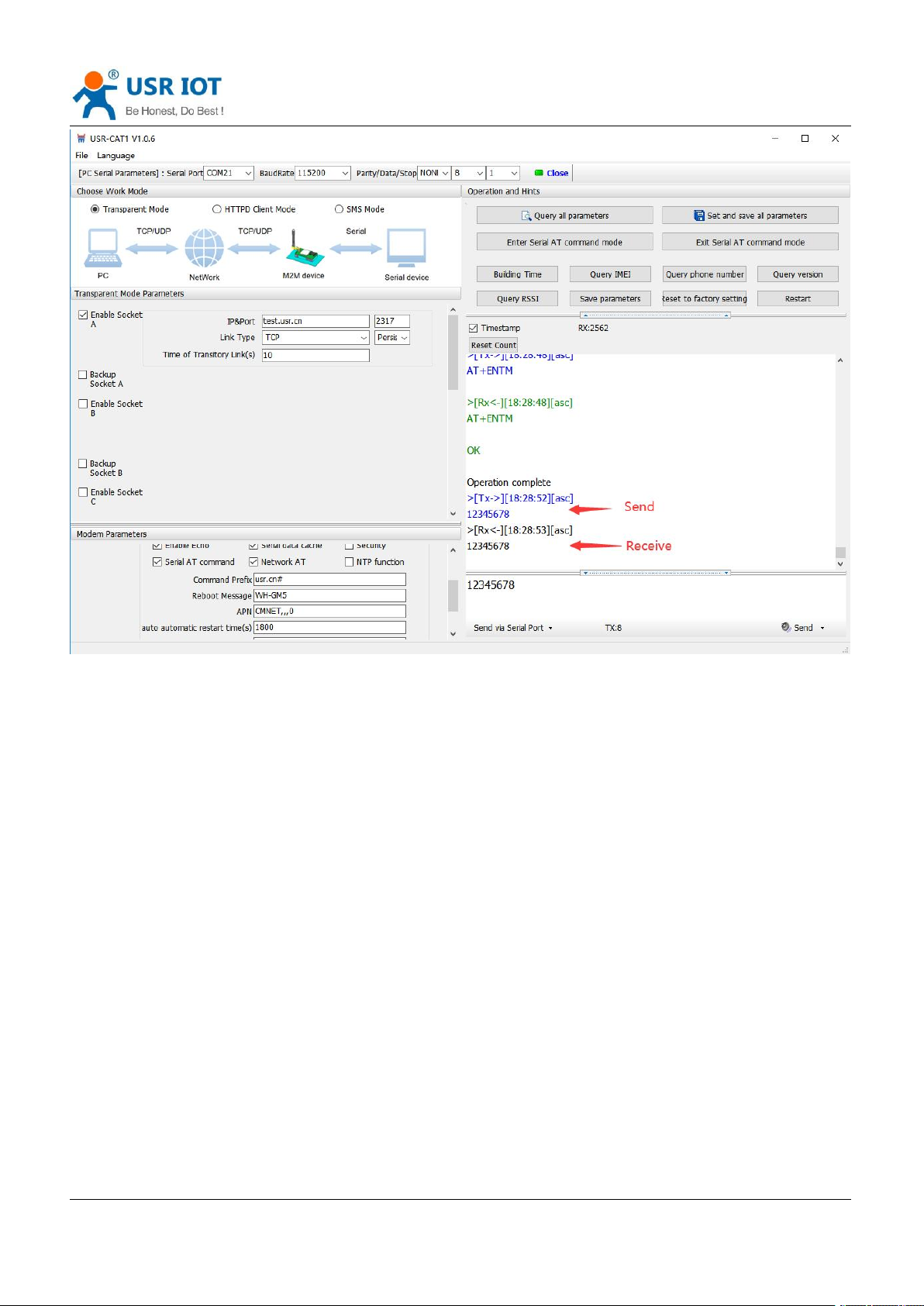
Test
Connect the serial port of USR-G771-E to the computer via a RS232 serial to USB cable, send data from the
utility, the test server will return the same data to serial port.
Page 13
USR-G771-E User Manual Technical Support: h.usriot.com
Jinan USR IOT Technology Limited www.pusr.com
13
Page 14
Jinan USR IOT Technology Limited www.pusr.com
14
5.2. HTTPD Client Mode
USR-G771-E User Manual Technical Support: h.usriot.com
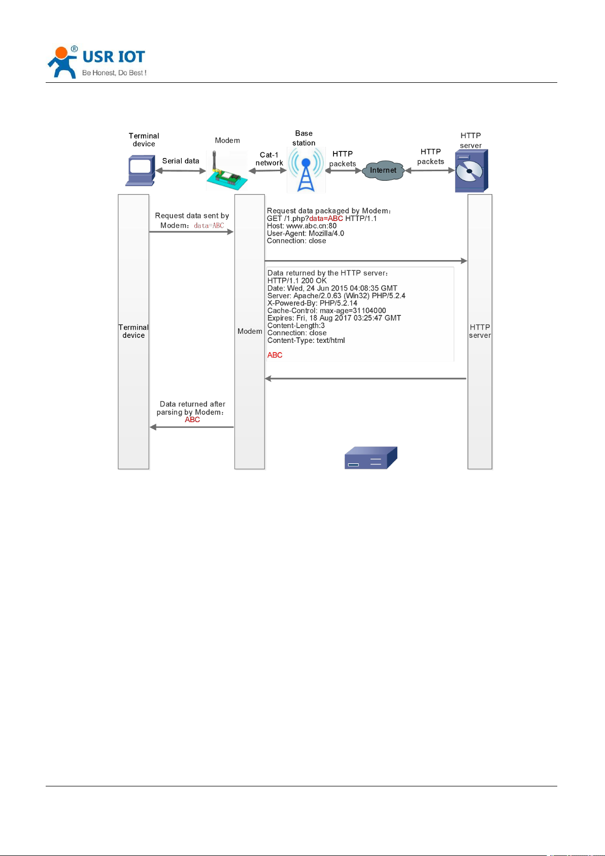
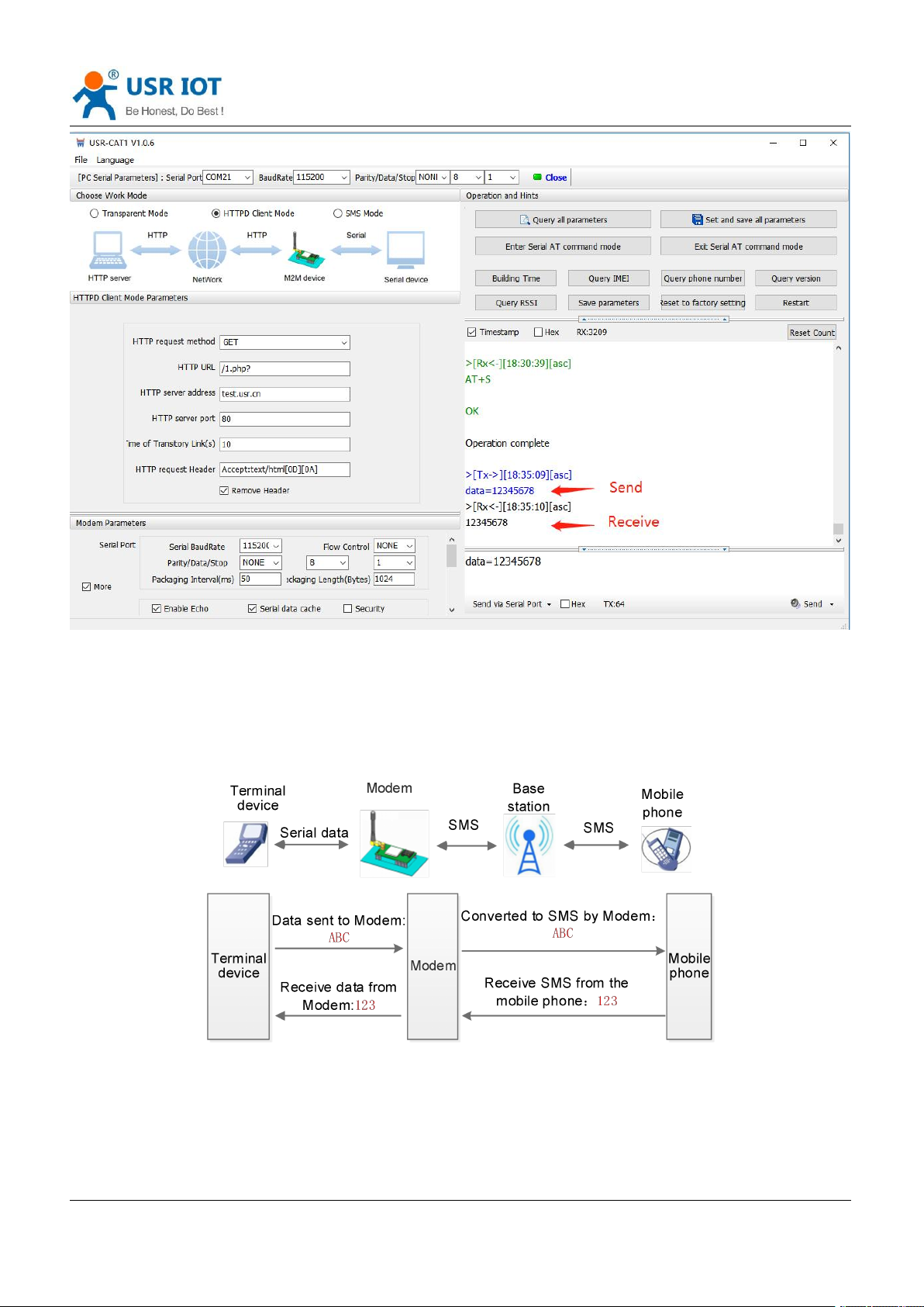
In this mode, user’s terminal device can send request data to the specified HTTP server through this modem,
then the modem receives data from HTTP server, parses and sends data to the serial device.
User does not need to pay attention to the data conversion process between the serial data and the network
data packet, and can achieve the data request from the serial device to the HTTP server through simple
parameter settings.
The modem will filter out the received HTTP protocol header data by default, only output user data to the
serial port. Users can choose whether to filter by AT command.
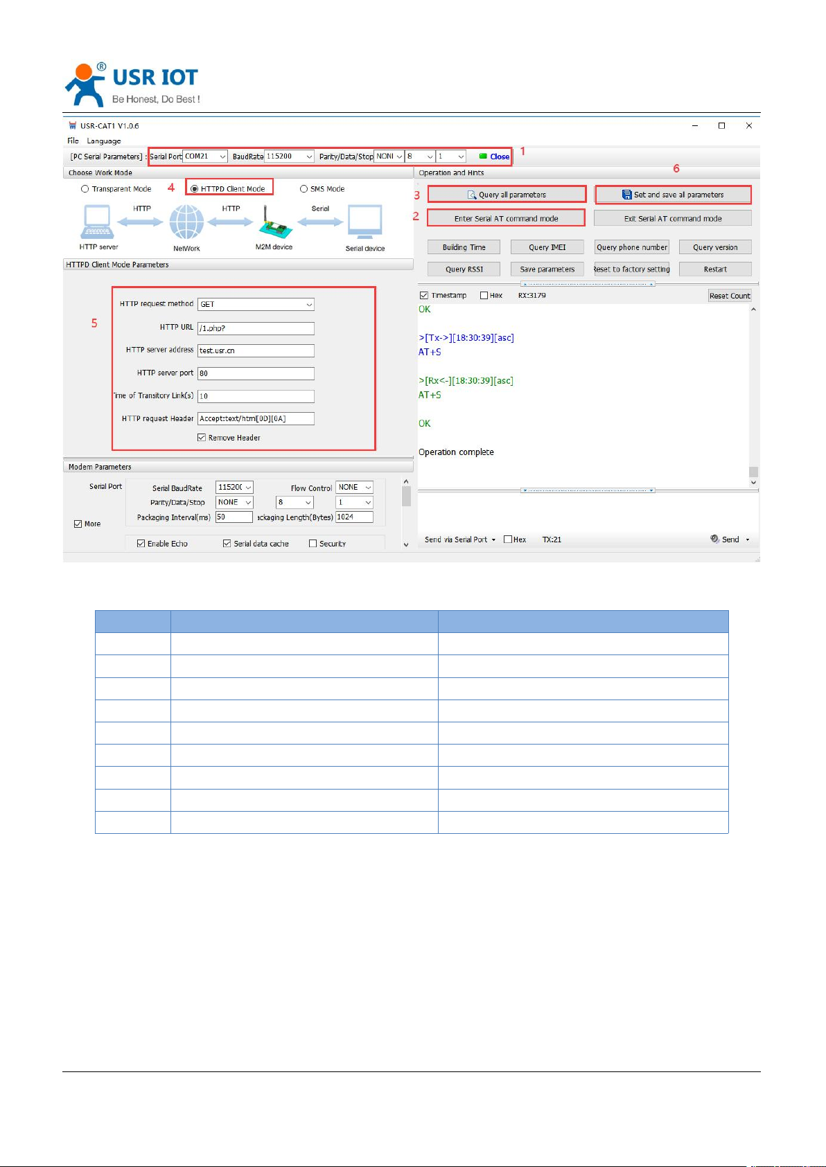
Set parameters by the utility:
Page 15
USR-G771-E User Manual Technical Support: h.usriot.com
Jinan USR IOT Technology Limited www.pusr.com
15
Command
Operation
1
+++a
Enter serial AT command mode
2
AT+WKMOD=HTTPD
Set the work mode to HTTPD Client
3
AT+HTPTP=GET
Set the HTTP request type to GET
4
AT+HTPURL=/1.php?
Set the HTTP URL
5
AT+HTPSV=test.usr.cn,80
Set the HTTP server address and port
6
AT+HTPHD=Accept:text/html[0D][0A]
Set the HTTP request header
7
AT+HTPTO=10
Set the time of transitory link
8
AT+HTPPK=ON
Set whether to filter HTTP header
9
AT+S
Save parameters and restart the modem
Set by AT command:
Test
After the NET light is on, send the data in the format of "data =". After the data is sent successfully, server will
return the data.
Page 16
USR-G771-E User Manual Technical Support: h.usriot.com
Jinan USR IOT Technology Limited www.pusr.com
16
5.3. SMS Mode
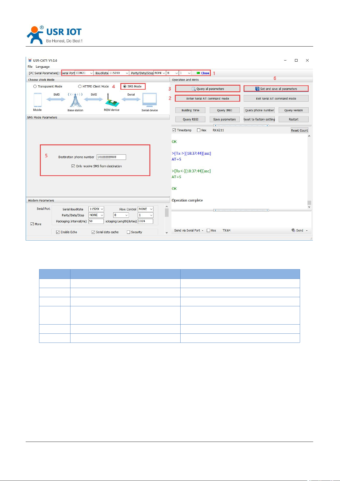
In this mode, user's serial device can send SMS to the specified mobile phone and receive SMS from any
mobile phone. User can decide whether to transmit the data of the specified mobile phone to the serial
device through settings.
Users can send and receive SMS to check the serial device status remotely via G771-E.
Page 17
Jinan USR IOT Technology Limited www.pusr.com
17
Set by the utility:
Command
Operation
1
+++a
Enter serial AT command mode
2
AT+WKMOD=SMS
Set the work mode to SMS
3
AT+DSTNUM=10086
Set the destination phone number
4
AT+SMSFLT=ON
Enable only receive SMS from source
number
5
AT+VOLTEEN=ON
Enable VOLTE function
6
AT+S
Save the parameters and restart
USR-G771-E User Manual Technical Support: h.usriot.com
Set by AT command:
Note:
1. You need to add the international number before the destination phone number.
2. When only receive SMS from source number is enabled, other phone numbers can still query or set parameters.
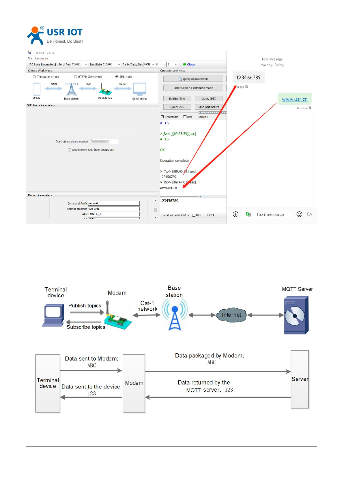
Test
When the NET light is on, we can send and receive data in both directions via SMS with destination phone
number.
Page 18
USR-G771-E User Manual Technical Support: h.usriot.com
Jinan USR IOT Technology Limited www.pusr.com
18
5.4. MQTT Mode
Note: This function is only supported by firmware version 1.3.25 and above.
Page 19
USR-G771-E User Manual Technical Support: h.usriot.com
Jinan USR IOT Technology Limited www.pusr.com
19
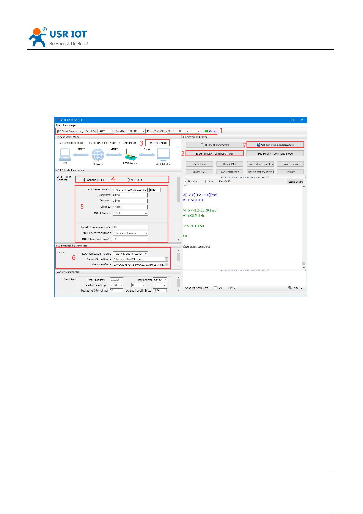
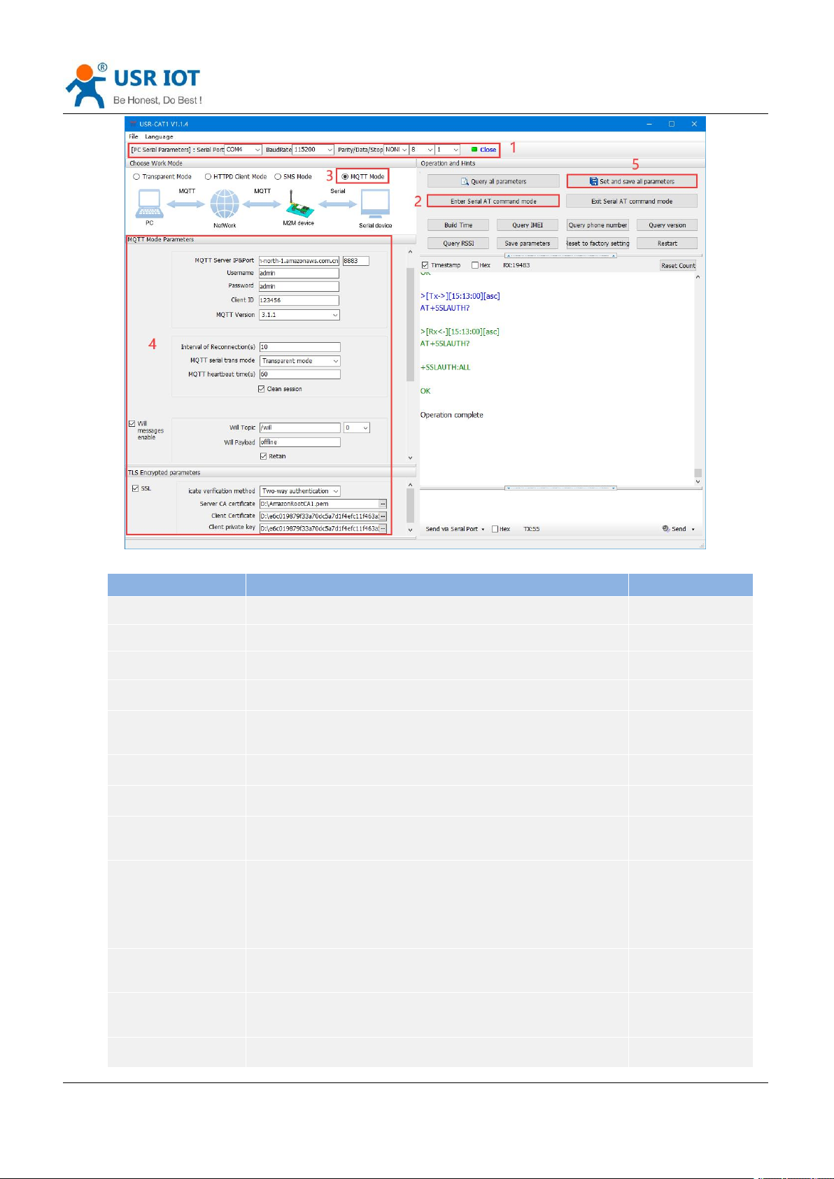
In this mode, USR-G771 works as an MQTT Client, which can help users quickly access the built private MQTT
server or public MQTT IoT cloud platform. Users do not need to pay attention to the data conversion process
between serial port data and network data packets, and can realize data transparent transmission between
serial port and server only through simple parameter settings.
USR-G771 supports quick access to general MQTT server and Alibaba Cloud, and supports multi-topic data
publishing and data subscription.
Setup software is like below:
5.4.1.Generic MQTT
USR-G771 supports connection to standard MQTT protocol IoT platforms, such as Baidu Cloud, Tencent
Cloud, Huawei Cloud, AWS Cloud, etc., and supports reconnection interval configuration to adapt to different
MQTT servers. Support SSL/TLS encryption, and the authentication mode can choose not to verify the
certificate, one-way authentication certificate and two-way authentication certificate.
Page 20
USR-G771-E User Manual Technical Support: h.usriot.com
Jinan USR IOT Technology Limited www.pusr.com
20
Options
Descriptions
Default
MQTT Mode
Whether to enable MQTT mode
OFF
MQTT Version
V3.1, V3.1.1
V3.1.1
MQTT Server IP
MQTT server domain name or IP address
cloudmqtt.usr.cn
Port
MQTT server port
1883
Client ID
MQTT client identifier. Not repeatable when connected to the
same MQTT server.
123456
Username
Username for MQTT connection authentication
admin
Password
Password for MQTT connection authentication
admin
Interval of
Reconnection
Interval between next reconnection after MQTT disconnection,
unit: s.
5
MQTT heartbeat time
MQTT protocol heartbeat time, unit: s.
Note: Alibaba Cloud requires that the heartbeat can be set within
30--1200 seconds, and it is recommended to set it to 300 seconds
when connecting to Alibaba Cloud.
60
MQTT serial trans
mode
Transparent mode, distribution mode
Transparent mode
Clean session
MQTT protocol connection flag, used to control the lifetime of
session state.
Enable
Will messages enable
MQTT connection flag, when the network connection is closed, the
Enable
Page 21

USR-G771-E User Manual Technical Support: h.usriot.com
Jinan USR IOT Technology Limited www.pusr.com
21
server must publish the will message, and the client subscribing to
the will topic will receive the set will.
Will topic
Will topic
/will
Will payload
Will content
offline
QOS
QOS of the will, can be set:
0: at most once.
1: at least once.
2: Accurate once.
0
Retain
Keep will message
Enable
SSL
Support SSL3.0, TLS1.0, TLS1.1 and TLS1.2 version protocols.
Authentication methods can be selected:
Do not verify certificate: Only implement data layer
transmission decryption, and do not verify the identity of the
other party during the handshake process.
Verify server certificate: the client will verify the server
certificate during the handshake, and the client needs to
preset the root certificate of the server.
Two-way authentication: The client and the server verify each
other's identity, and the server root certificate, client
certificate, and client private key need to be preset.
Do not verify
certificate
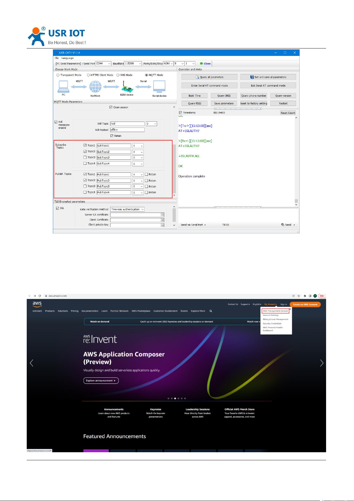
5.4.2.Subscribe/Public Topics
Users can configure the subscribe topics, public topics, topic numbers, QOS, whether to retain will message
via the setup software. G771-E supports two MQTT modes, transparent mode and distribution mode.
In transparent mode, the data received by the serial port is transparently transmitted to the associated topic
as the payload of the topic, and up to 4 publish/subscribe topics are supported. Add the identifier of the topic
in the distribution mode, and after the module receives the serial port data, it will push it to the associated
topic according to the identifier. The identifier defaults to the topic number, and the identifier and payload are
separated by commas. The message format is: symbol, <payload>
Page 22
USR-G771-E User Manual Technical Support: h.usriot.com
Jinan USR IOT Technology Limited www.pusr.com
22
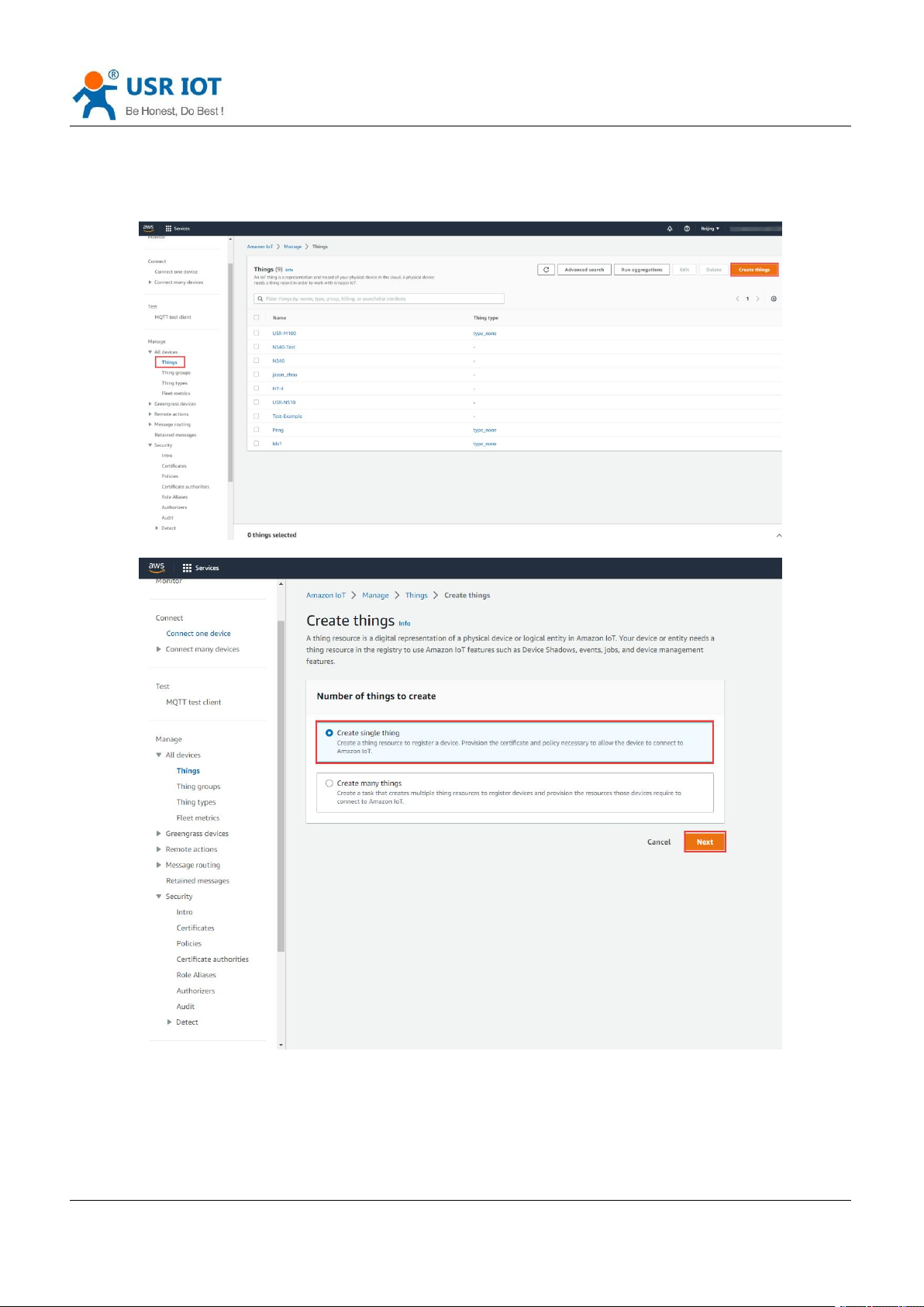
5.4.3.AWS IoT Service
G771-E supports connecting to AWS IoT platform via MQTT.
Visit https://aws.amazon.com/, log in to the IoT console, choose AWS Management Console.
Page 23
USR-G771-E User Manual Technical Support: h.usriot.com
Jinan USR IOT Technology Limited www.pusr.com
23
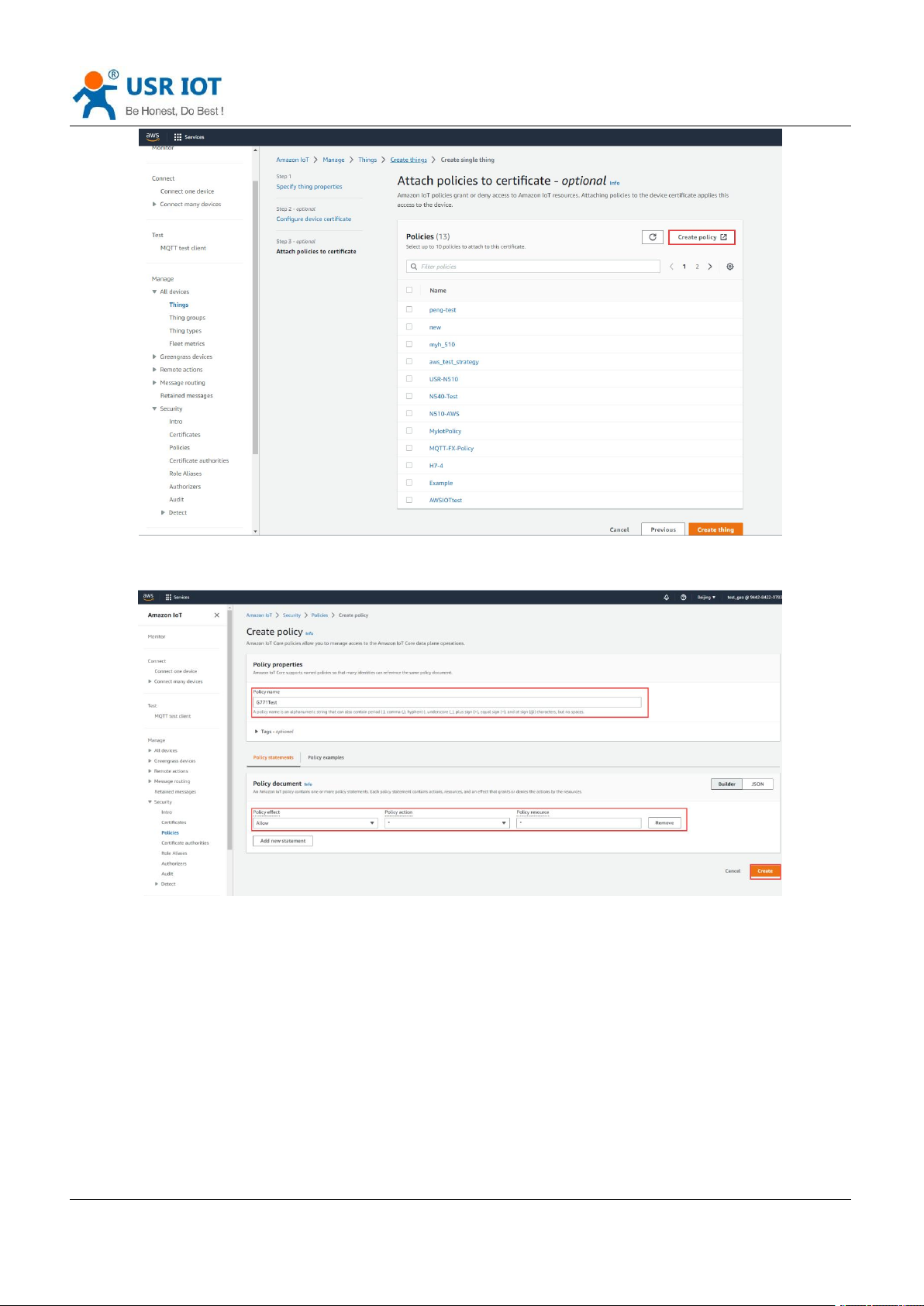
5.4.3.1. AWS IoT Configuration
1. In Things, click to Create things--Create single thing.
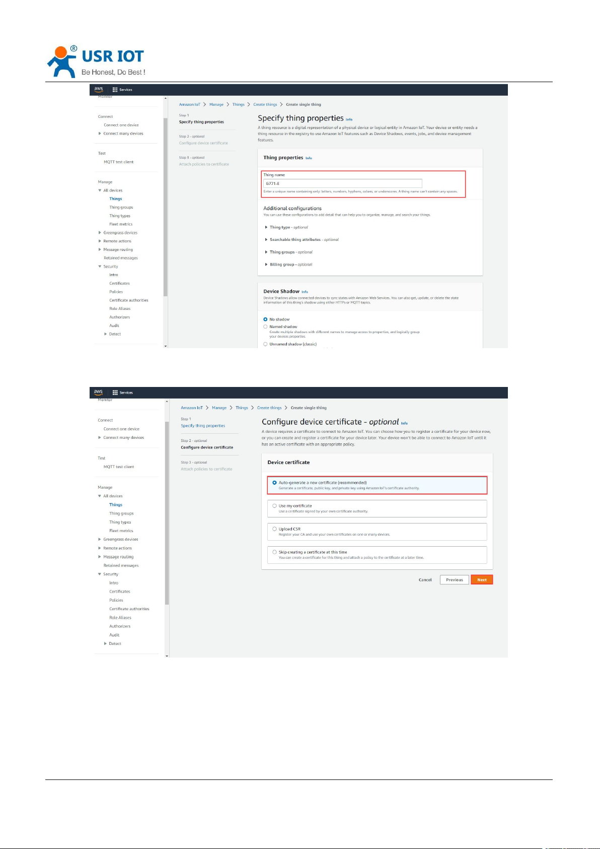
2. Edit the Thing name, click Next.
Page 24
USR-G771-E User Manual Technical Support: h.usriot.com
Jinan USR IOT Technology Limited www.pusr.com
24
3. Choose Auto-generate a new certificate. Then click Next.
4. Create Policy.
Page 25
USR-G771-E User Manual Technical Support: h.usriot.com
Jinan USR IOT Technology Limited www.pusr.com
25
5. Edit the Policy name, change the Policy effect to Allow, the Policy action and Policy resource to *.
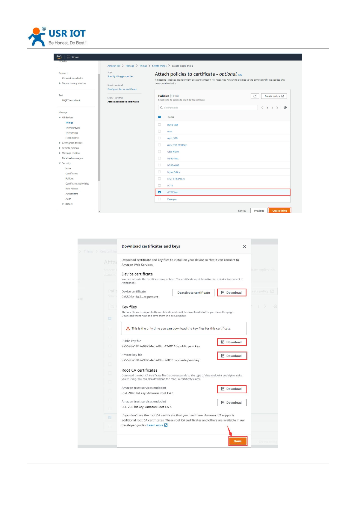
6. After created, return to the previous certificate interface, attach the new created policy to this certificate.
Then click Create thing.
Page 26
USR-G771-E User Manual Technical Support: h.usriot.com
Jinan USR IOT Technology Limited www.pusr.com
26
7. Download 4 certificates in below interface. Then click Done.
Page 27
USR-G771-E User Manual Technical Support: h.usriot.com
Jinan USR IOT Technology Limited www.pusr.com
27
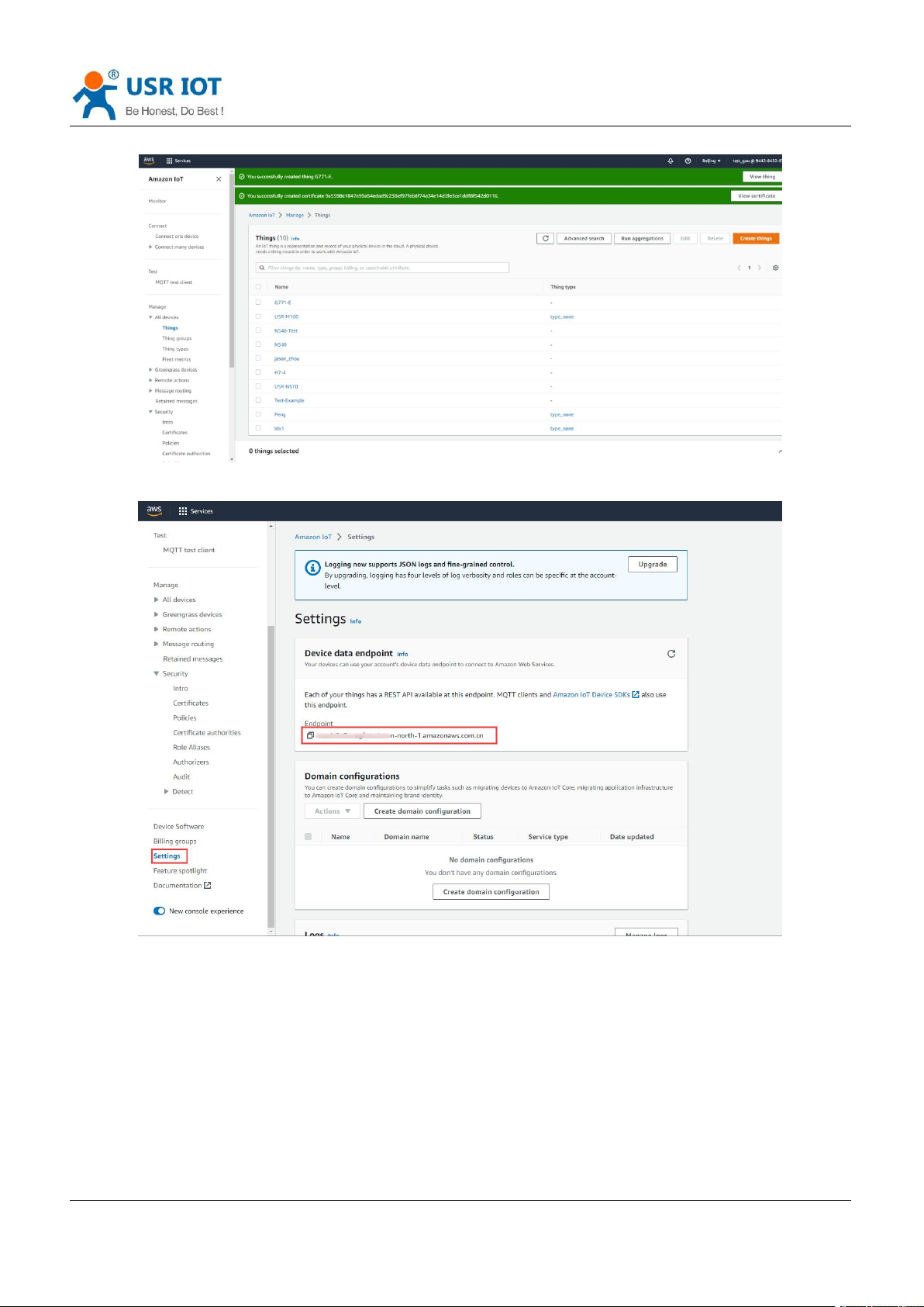
8. Now new thing has been added successfully.
9. In Settings, copy the AWS server address that needs to be filled in G771-E device.
Page 28

USR-G771-E User Manual Technical Support: h.usriot.com
Jinan USR IOT Technology Limited www.pusr.com
28
5.4.3.2. G771-E Device Configuration
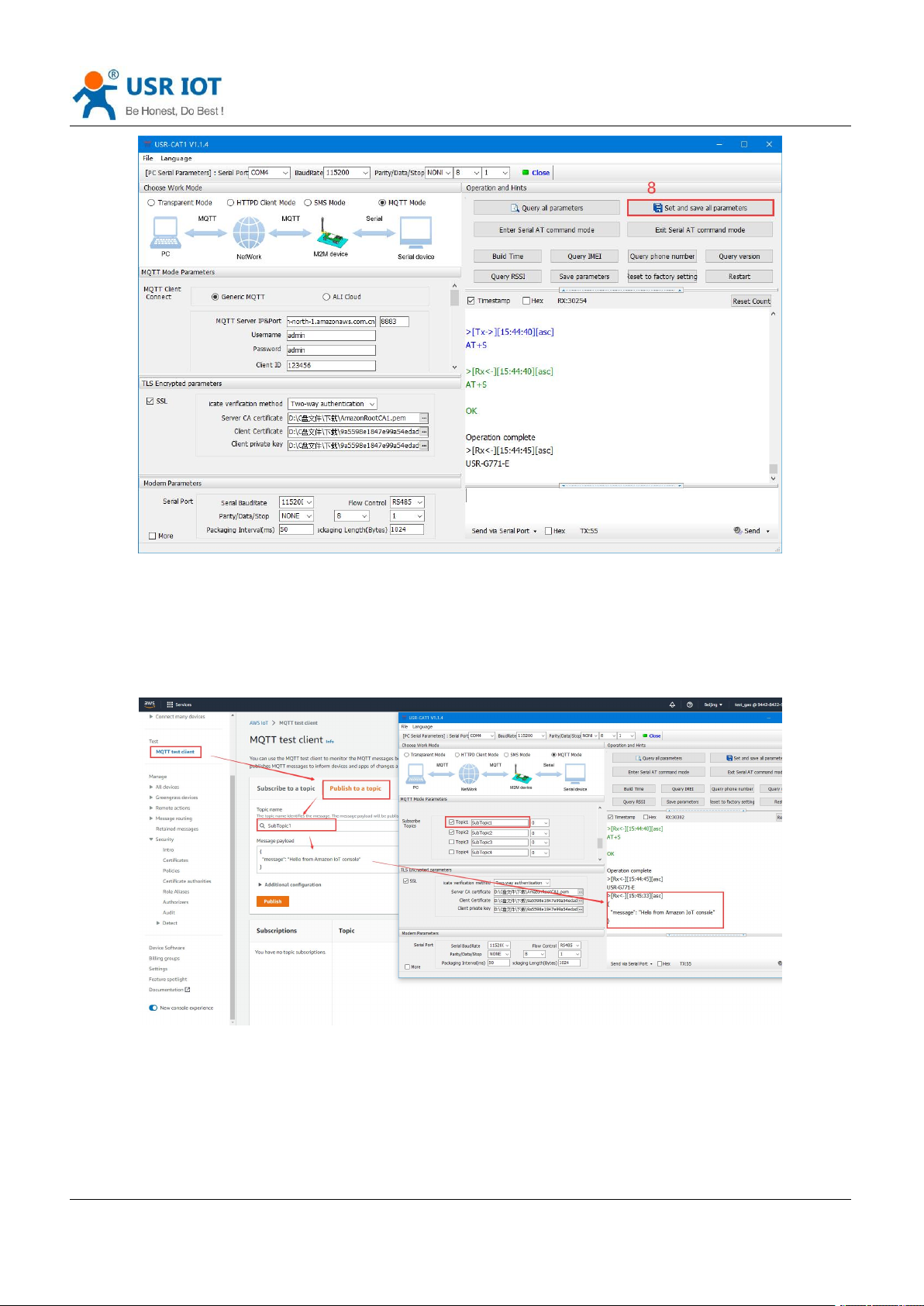
You can use an RS232 or RS485 to USB adaptor to connect the serial port of G771-E device to the computer.
Then open the CAT1 setup software to configure the MQTT parameters.
1. Here we choose Generic MQTT mode, the MQTT server IP should be the one that we copied in AWS
Cloud, and the MQTT port is 8883. Username and password can be any value. Configure the subscribe
and publish topics.
2. Upload the created certificates to G771-E device. We need to upload the Server CA
certificate(rootCA.pem), Client certificate(certificate.pem.crt) and Client private key(private.pem.key).
3. After configuring all parameters, click to Set and save all parameters. The device will restart automatically.
Page 29
USR-G771-E User Manual Technical Support: h.usriot.com
Jinan USR IOT Technology Limited www.pusr.com
29
5.4.3.3. Data Transmission Test
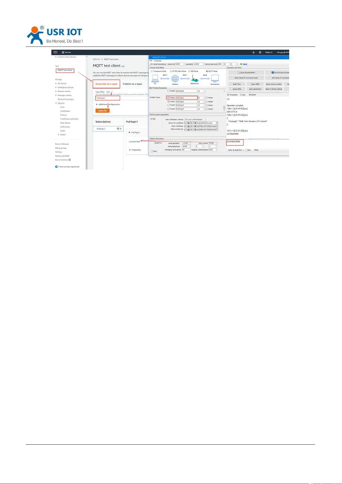
In AWS IoT platform, click MQTT test client, publish data from AWS to the subscribed topic of G771 device ,
we can receive it from the serial port of G771-E device.
Subscribe the publish topics of G771-E device in AWS, we can receive the data sent from the serial port of
G771-E device.
Page 30
USR-G771-E User Manual Technical Support: h.usriot.com
Jinan USR IOT Technology Limited www.pusr.com
30
In this way, we can achieve the bi-directional communication between serial device and AWS cloud via
G771-E device.
Page 31
USR-G771-E User Manual Technical Support: h.usriot.com
Jinan USR IOT Technology Limited www.pusr.com
31
6. General Function
6.1. Identity Package
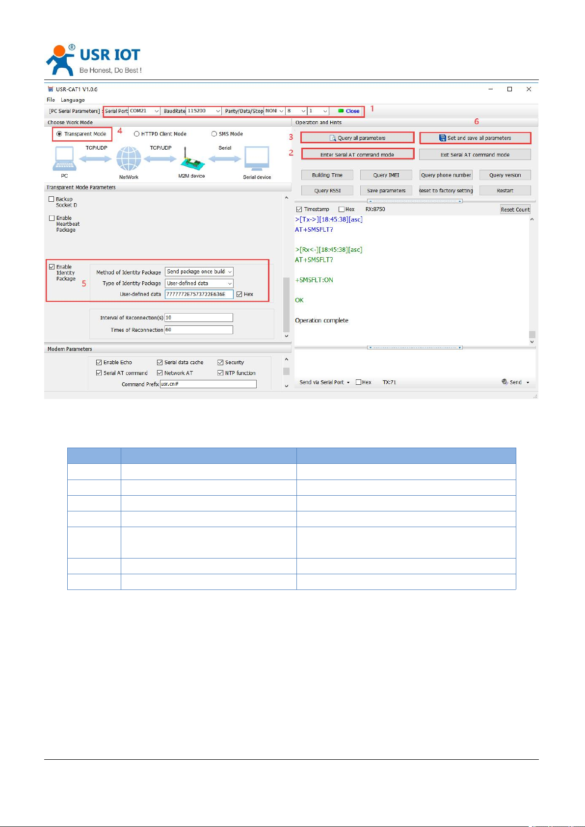
In transparent mode, user can set the device to send identity package to the server. Identity package is
intended to allow the server to identify the data from which device or to use it as a password to obtain
authorization for the server's functions.
Identity package can be sent when the modem establishes a connection with the server, or as the prefix of
each data packet or both.
Identity package data can be ICCID code, IMEI code, SN, CLOUD or User-defined data.
ICCID: Unique SIM identification code, for applications based on SIM card identification.
IMEI: Unique identification code of the Internet modem, which is mainly used in device identification, has
nothing to do with SIM card.
SN: Serial number.
USER: User-defined data.
CLOUD: Set the device ID and password when connecting to USR Cloud, sent when building connection.
Set by the utility:
Page 32
USR-G771-E User Manual Technical Support: h.usriot.com
Jinan USR IOT Technology Limited www.pusr.com
32
Command
Operation
1
+++a
Enter AT command mode
2
AT+WKMOD=NET
Set the work mode to NET
3
AT+REGEN=ON
Enable identity package function
4
AT+REGTP=USER
Set the type to User-defined
5
AT+REGDT=7777772E7573722E636
E
Set the User-defined data in HEX.
6
AT+REGSND=LINK
Send the package as the prefix of the data
7
AT+S
Save parameters and restart
Set by AT command:
Page 33
USR-G771-E User Manual Technical Support: h.usriot.com
Jinan USR IOT Technology Limited www.pusr.com
33
6.2. Heartbeat Package
In transparent mode, user can send the heartbeat package from the module to the network side or serial port
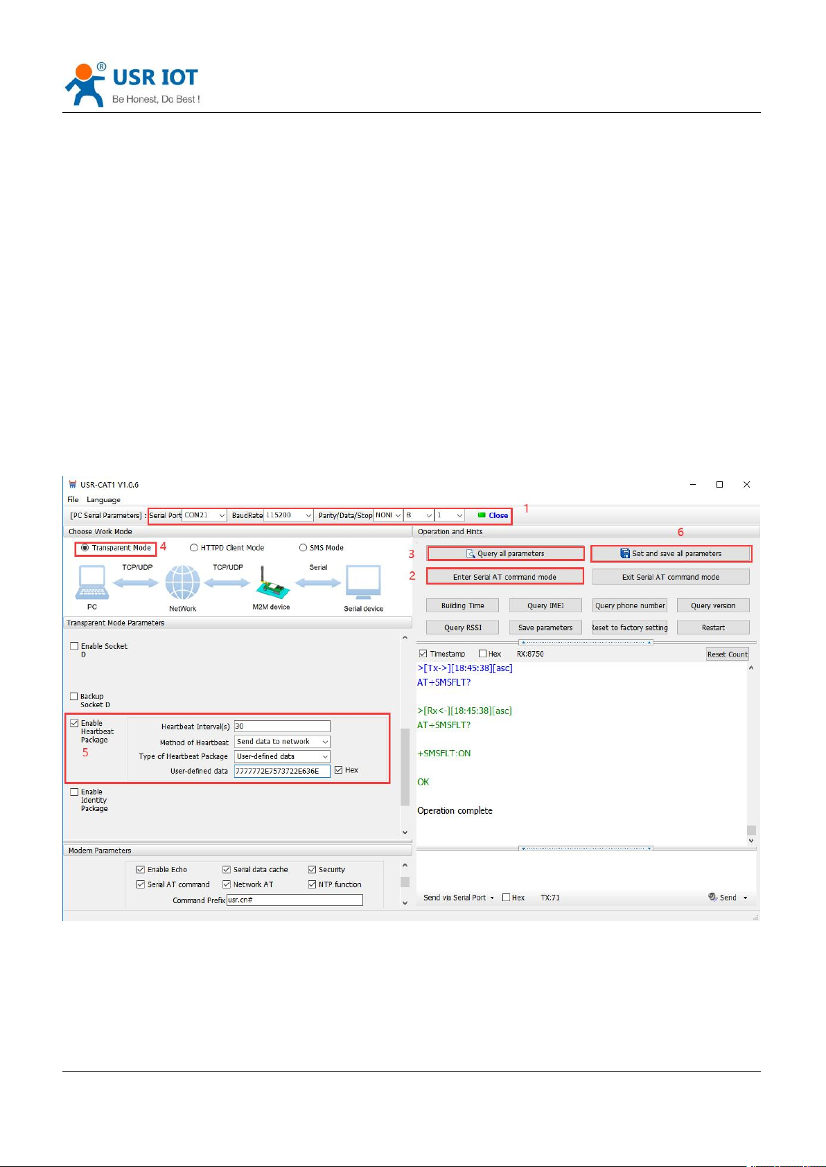
device .
Sending to the network is to ensure the normal connection of the module and let the server know the online
status of the module. User can also set the serial heartbeat to a fixed query command instead of sending from
server to save the traffic.
Heartbeat package can be ICCID code, IMEI code, SN, LBS or user-defined data.
ICCID: Unique SIM identification code, for applications based on SIM card identification.
IMEI: Unique identification code of the Internet modem, which is mainly used in device identification, has
nothing to do with SIM card.
SN: Serial number.
USER: User-defined data.
LBS: Current latitude, longitude of the device and time.
Set by the utility:
Page 34

USR-G771-E User Manual Technical Support: h.usriot.com
Jinan USR IOT Technology Limited www.pusr.com
34
Command
Operation
1
+++a
Enter AT command mode
2
AT+HEARTEN=ON
Enable heartbeat package function
3
AT+HEARTTP=NET
Send the heartbeat package to network side
4
AT+HEARTSORT=USER
Set the type to User-defined
5
AT+HEARTDT=7777772E7573722E6
36E
Set the User-defined data in HEX.
6
AT+HEARTTM=30
Set the heartbeat interval
Set by AT command:
You also need to set the socket parameters. After setting all parameters, save and restart the modem.
Note:
1, Network heartbeat package: In transparent mode, it will only be sent when there is no data sent to network
within one heartbeat interval.
2, Serial heartbeat package: In transparent mode, it will always be sent to serial port according to the set
interval.
6.3. Socket Distribution Protocol
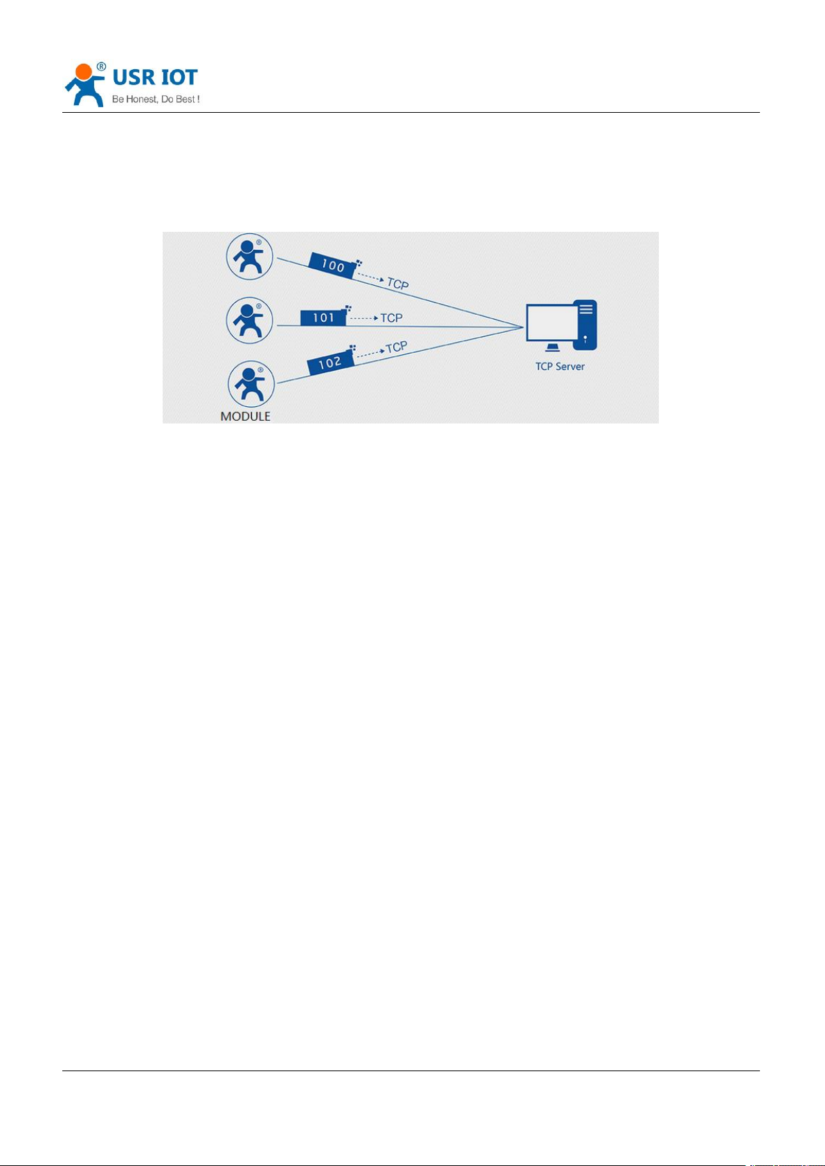
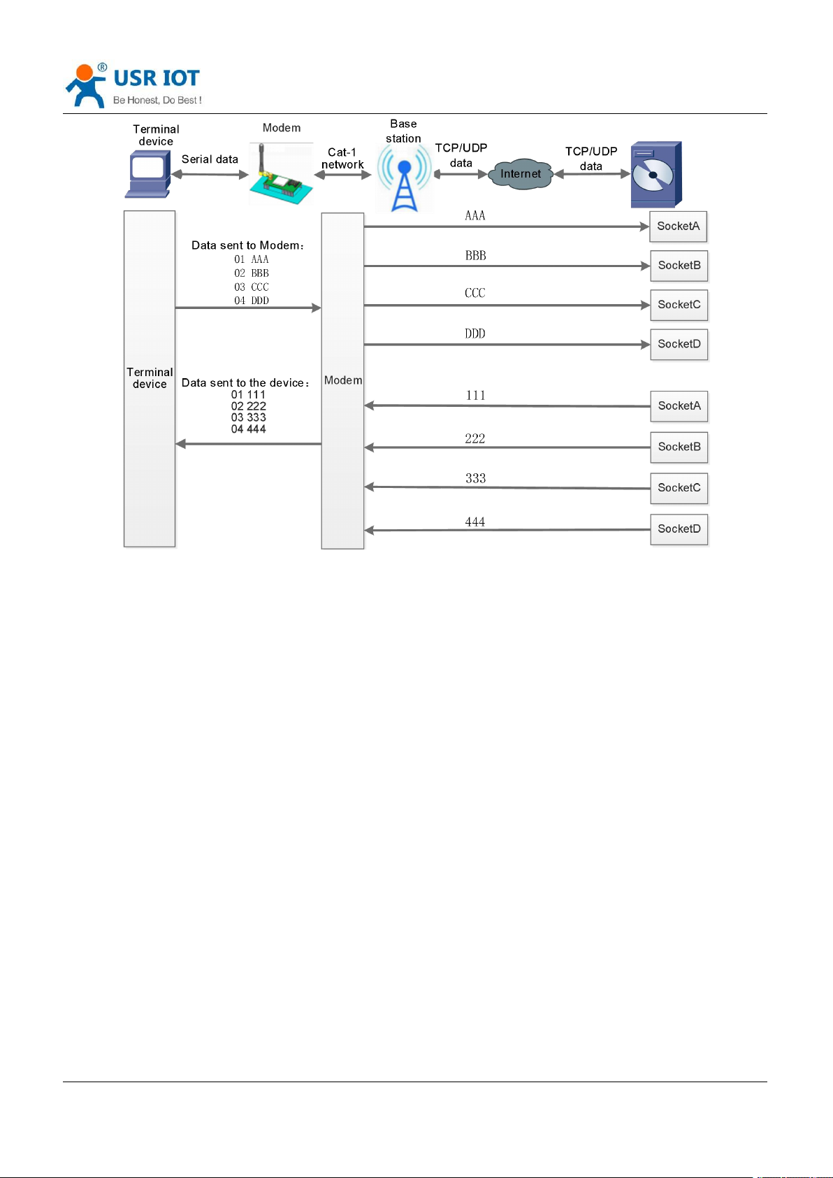
USR-G771-E supports socket distribution protocol. When a device is connected to multiple sockets, can send
different serial data to different servers via this protocol. Data returned from different server will also be sent
to the serial port with the socket distribution protocol.
For detailed protocol, please refer to another document Socket distribution protocol.
Page 35
USR-G771-E User Manual Technical Support: h.usriot.com
Jinan USR IOT Technology Limited www.pusr.com
35
Socket distribution protocol data follows the packaging mechanism, the total length of the real data and
socket distribution protocol must be less than the packaging length.
This function is valid in transparent mode, disabled by default, can be set via AT command: AT+SDPEN.
6.4. Backup Socket
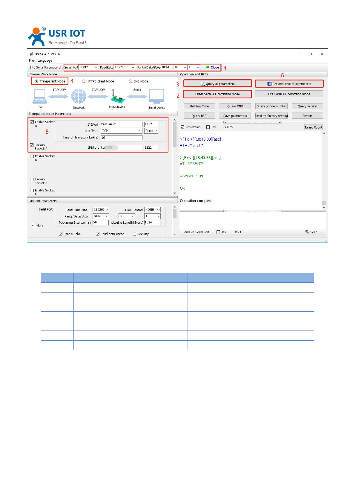
In transparent mode, you can set one backup socket for each socket, the modem will try to connect to backup
server when cannot connect to the main server. This function defaults to be unchecked.
Set by the utility:
Page 36
USR-G771-E User Manual Technical Support: h.usriot.com
Jinan USR IOT Technology Limited www.pusr.com
36
Command
Operation
1
+++a
Enter serial AT command mode
2
AT+WKMOD=NET
Set the work mode to Transparent mode
3
AT+SOCKAEN=ON
Enable Socket A
5
AT+SOCKA=TCP,test.usr.cn,2317
Set the remote IP and port of Socket A
6
AT+SOCKABKEN=ON
Enable Socket backup function
7
AT+SOCKABK=TCP,test.usr.cn,2317
Set the backup server address and port
8
AT+S
Save all parameters and restart
Set by AT commands:
6.5. SSL/TLS Encryption
Note: This function is only supported by firmware version V1.3.25 and above.
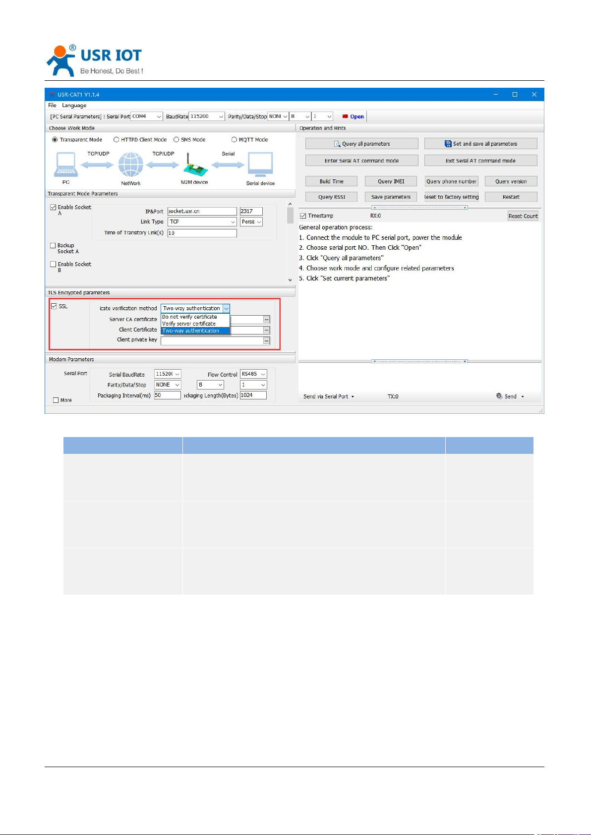
In HTTPD Client mode and MQTT mode, the device supports SSL/TLS encryption. If the target server enables
SSL certificate verification, you need to configure the SSL encryption parameters. It supports SSL3.0, TLS1.0,
TLS1.1, and TLS1.2 versions, and the authentication method can choose not to verify certificate, verify server
certificate, and two-way verification authentication.
Page 37
USR-G771-E User Manual Technical Support: h.usriot.com
Jinan USR IOT Technology Limited www.pusr.com
37
Authentication mode
Descriptions
Recommendations
Not to verify certificate
It only implements data layer transmission decryption, and does
not verify the identity of the other party during the handshake
process.
No encryption
required.
Verify server certificate
During the handshake, the client will verify the server certificate,
and the client needs to preset the root certificate of the server.
Scenario for
verifying device
legitimacy
Two-way verification
authentication
The client and the server verify each other's identity, and the
server root certificate, client certificate, and client private key
need to be preset.
Data transmission
scenarios with
strong security
6.6. Security
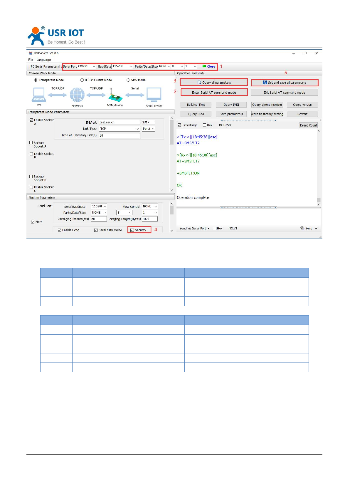
When enable Security function, after enter AT command mode, you need to input the correct password to
login. After logging, you can also change the password by sending the login command again.
The modem will automatically exit AT command mode if there is no login command within 30s.
Set by the utility:
Page 38
USR-G771-E User Manual Technical Support: h.usriot.com
Jinan USR IOT Technology Limited www.pusr.com
38
Command
Operation
1
+++a
Enter serial AT command mode
2
AT+SAFEATEN=ON
Enable security function
3
AT+S
Save all parameters and restart
Command
Operation
1
+++a
Enter serial AT command mode
2
AT+SIGNINAT=usr_cn
Login command
3
AT+VER
Query the firmware version
4
AT+SIGNINAT=usr_cn#
Change the password
5
AT+S
Save all parameters and restart
Set by AT commands:
Enable:
Change the password:
Page 39
USR-G771-E User Manual Technical Support: h.usriot.com
Jinan USR IOT Technology Limited www.pusr.com
39
Command
Operation
1
+++a
Enter serial AT command mode
2
AT+NTPEN=ON
Enable NET function
3
AT+NTPSVR=cn.ntp.org.cn,us.ntp.org.c
n
Set the NTP server address
4
AT+NTPTM=60
Set the NTP calibration interval
5
AT+S
Save all parameters and restart
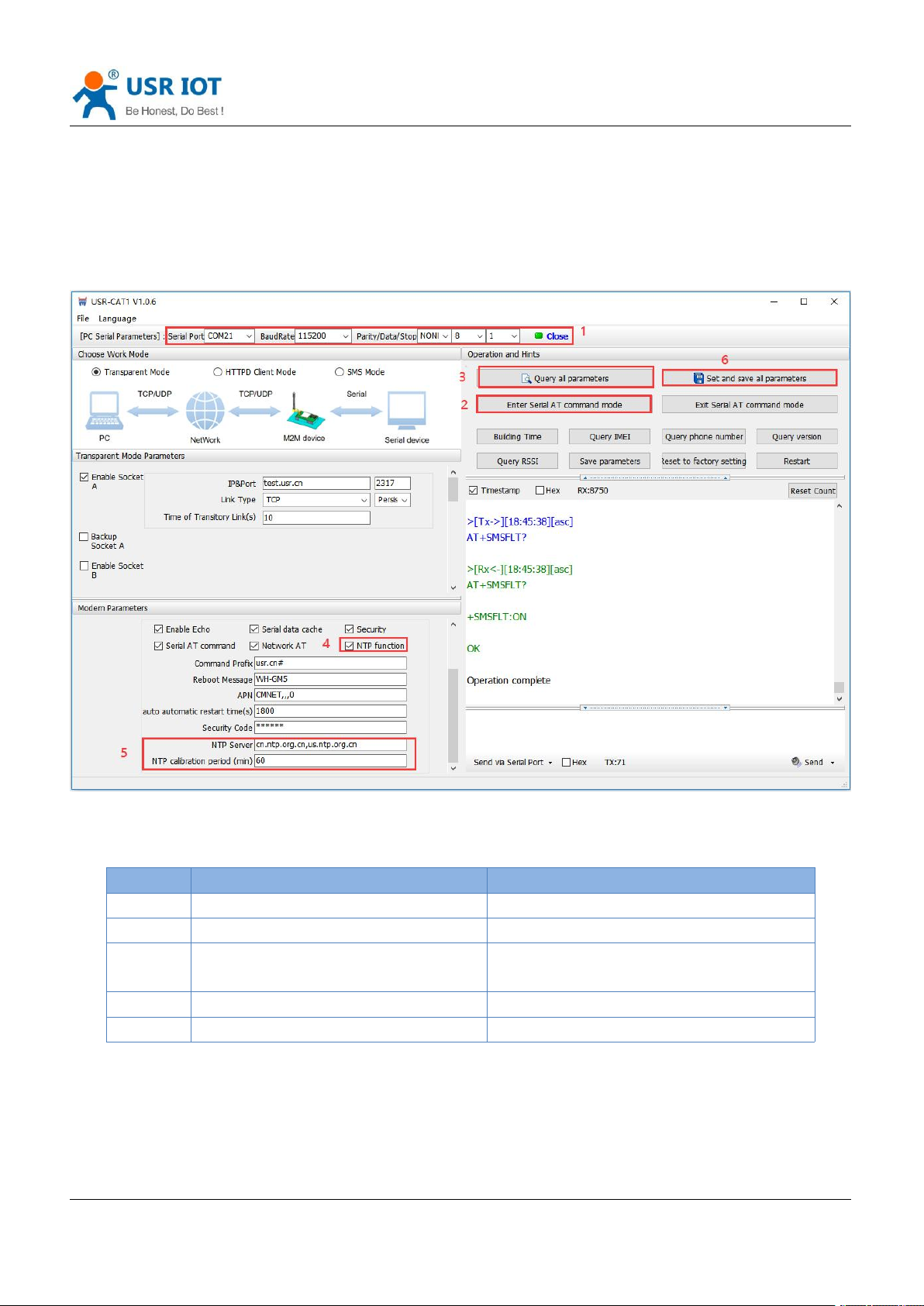
6.7. NTP
USR-G771-E supports connecting to the NTP server for time synchronization.
This function defaults to be disabled, support connecting to up to 4 NTP servers. User can send “AT+CCLK” or
“AT+CCLK?” to query the current time.
Set by the utility:
Set by AT commands:
Page 40
USR-G771-E User Manual Technical Support: h.usriot.com
Jinan USR IOT Technology Limited www.pusr.com
40
Command
Function
Default parameter
AT+LBS
Query station geolocation information
Empty
6.8. FTP Upgrade
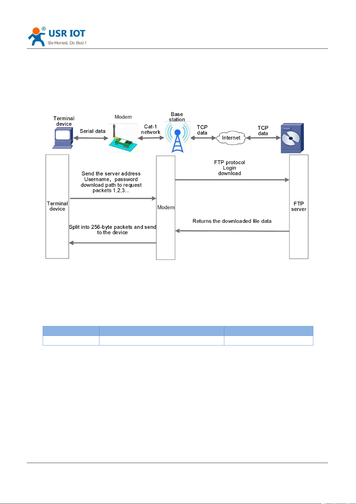
G771-E supports FTP upgrade protocol, user's device can request files on FTP server by special protocol
through serial port. The file of the server can be split into small packets with a maximum size of 256 bytes for
transmission, which is convenient for customer device to upgrade or download large files remotely.
For details, please refer to USR FTP Upgrade protocol.
6.9. Base Station Geolocation
USR-G771-E supports base station geolocation function, and can obtain general location of the device
through the operator's network. Base station positioning information can be obtained through serial AT
command or SMS AT command.
6.10. Firmware Upgrade
G771-E supports upgrading via FOTA or USB. For FOTA upgrading, please contact us for technical support.
Please also provide the IMEI and the firmware version of the device after connecting the device to the
network.
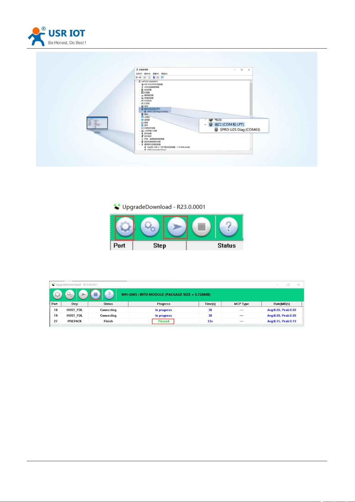
Here we introduce how to upgrade via USB port:
1. Hardware connection: Connect the USB port (only for upgrading) of G771-E to the computer.
2. Install the driver.
3. Press the “Reload” button and power on the device at the same time, release it and the device will be in
downloading mode. Download port is showing like below:
Page 41
USR-G771-E User Manual Technical Support: h.usriot.com
Jinan USR IOT Technology Limited www.pusr.com
41
4. Please contact the sales for upgrading tool. Find “UpgradeDownload.exe” under
UPGRADEDOWNLOAD\Bin.
5. Download the firmware.
6. Upgrade successfully. You can directly change to another device to upgrade. After all the devices are
upgraded, click “Stop”, then close the tool.
6.11. Restore to Factory Default Settings
1. Hardware reset: After power on, press the “Reload” button in the device for 3~15S to restore the device
to factory parameters.
2. Software reset: After enter AT command mode, send “AT+CLEAR” from the serial port to restore the
device.
Page 42
USR-G771-E User Manual Technical Support: h.usriot.com
Jinan USR IOT Technology Limited www.pusr.com
42
6.12. Timeout Restart
USR-G771-E supports timeout restart function, defaults to be enabled, 1800s. When there is no data in 30min,
the device will restart automatically. You can change it via AT command: AT+RSTIM.
7. AT Commands
AT command is used for controlling modem, for USR devices in transparent mode normally, you must enter
AT command mode at first, then you can send AT commands to configure or query the parameter settings.
After setting all parameters, restart the modem to make the settings take effect. Every time the modem
restart will work in work mode rather AT command mode.
Every AT command must add character carriage return <CR> and line feed <LF>. In Hex, <CR> is 0x0D
<LF> is 0x0A.
For detailed AT command set, please check in this link:
https://www.pusr.com/products/RS232/RS485-serial-to-Cat-1-771.html
7.1. AT Command Settings
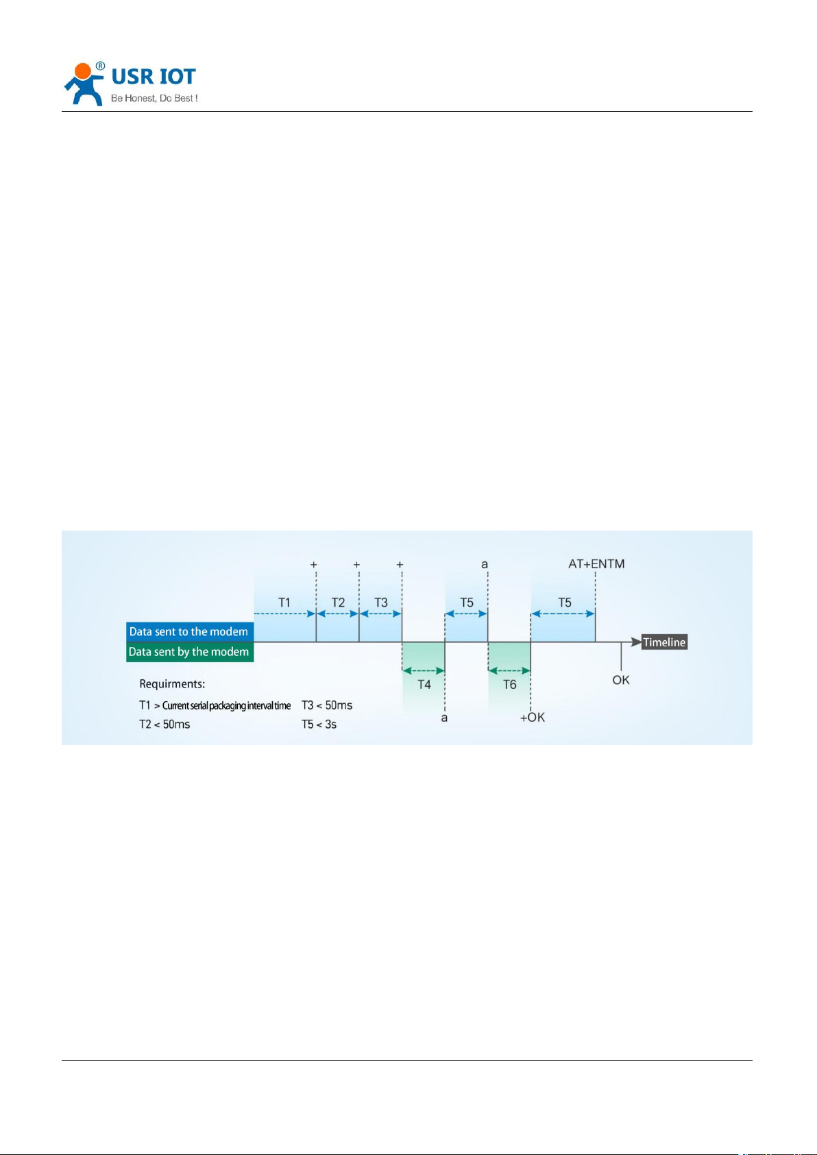
Enter AT command mode:
1. Send “+++” from the serial port, it will be a “a” returned.
2. Do not send any data within a serial port packaging interval before sending "+++".
3. After receiving “a”, send another “a” within 3s.
4. Receiving “+ok” means the device has changed to AT command mode.
5. Then can send AT commands to the device.
Exit AT command mode:
1. Send “AT+ENTM” from the serial port.
2. Receiving “+ok” means the device has exited AT command mode.
Page 43
USR-G771-E User Manual Technical Support: h.usriot.com
Jinan USR IOT Technology Limited www.pusr.com
43
7.2. Serial AT Commands
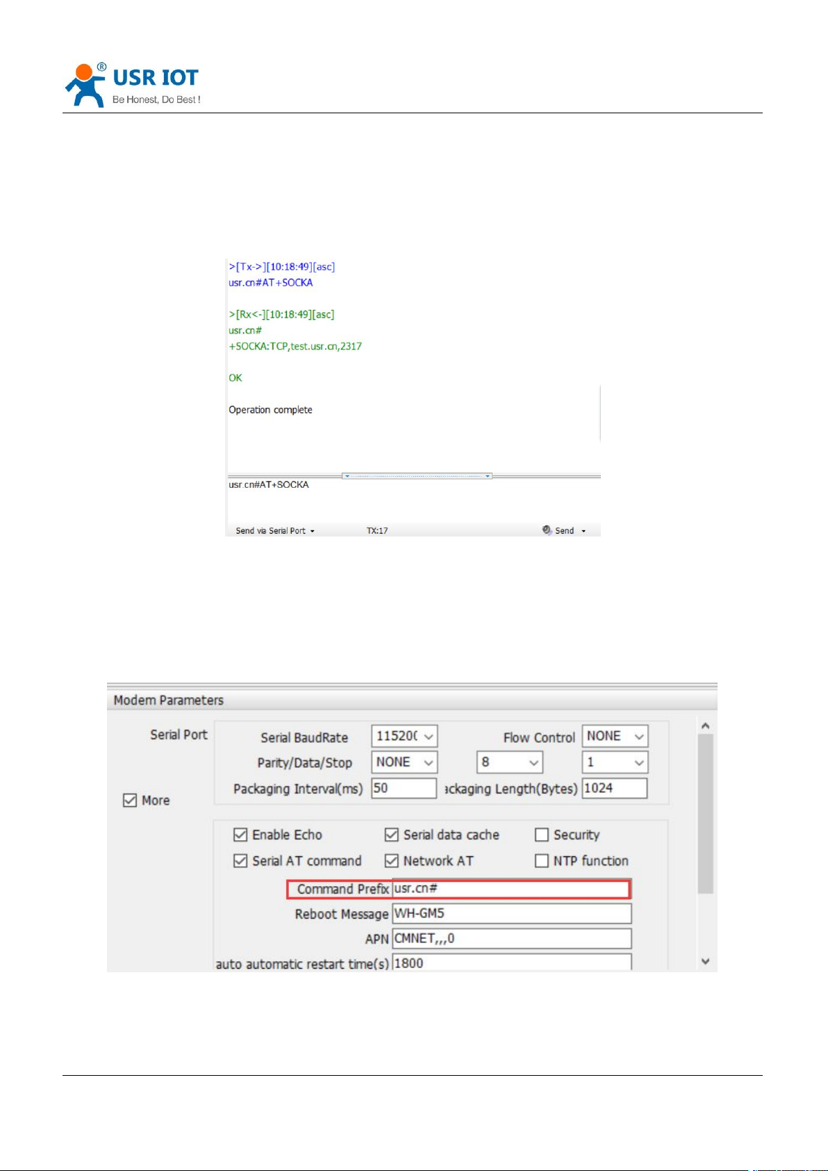
When enable “Serial AT command” function, you can directly send “Command prefix+AT command”in
transparent mode without changing to AT command mode. Command prefix defaults to “usr.cn#”.
Example: query socket A status, there is a carriage return and line feed after the AT command.
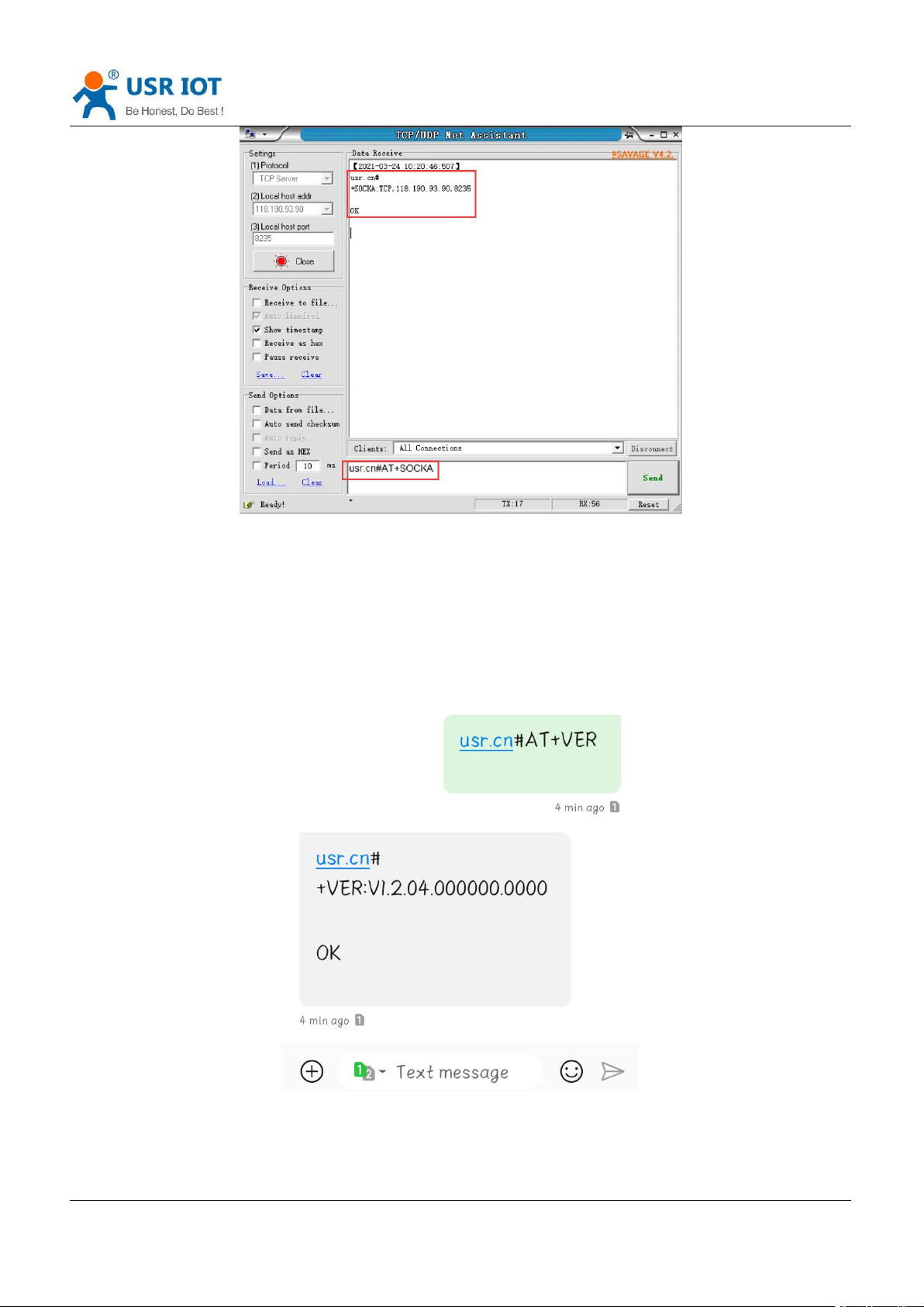
7.3. Network AT Commands
In transparent mode, you can also send “Command Prefix+AT command” from the network side to query or
change the modem’s parameter settings.
Example: query socket A status, there is a carriage return and line feed after the AT command.
Page 44
USR-G771-E User Manual Technical Support: h.usriot.com
Jinan USR IOT Technology Limited www.pusr.com
44
7.4. SMS AT Commands
If we know the phone number of the SIM card in G771-E, we can also query or modify the parameters of it by
sending SMS AT command.
For example: query firmware version, there is a carriage return and line feed after the AT command.
 Loading...