

Page 1
INSTALLATION AND
OPERATION MANUAL
“REGAL” SERIES
SALAMANDER BROILERS
FOR YOUR SAFETY:
DO NOT STORE OR USE GASOLINE
OR OTHER FLAMMABLE VAPORS OR
LIQUIDS IN THE VICINITY OF
THIS OR ANY OTHER
APPLIANCE
WARNING:
IMPROPER INSTALLATION, ADJUSTMENT,
ALTERATION, SERVICE OR MAINTENANCE
CAN CAUSE PROPERTY DAMAGE, INJURY,
OR DEATH. READ THE INSTALLATION,
OPERATING AND MAINTENANCE
INSTRUCTIONS THOROUGHLY
BEFORE INSTALLING OR
SERVICING THIS EQUIPMENT
AND RETAIN FOR FUTURE REFERENCE.
THIS PRODUCT HAS BEEN CERTIFIED AS
COMMERCIAL COOKING EQUIPMENT AND
MUST BE INSTALLED BY PROFESSIONAL
PERSONNEL AS SPECIFIED.
IN THE COMMONWEALTH OF MASSACHUSETTS
THIS PRODUCT MUST BE INSTALLED BY A
LICENSED PLUMBER OR GAS FITTER. APPROVAL
NUMBER: G-1-07-05-28
For Your Safety:
Post in a prominent location, instructions to be
followed in the event the user smells gas. This
information shall be obtained by consulting
your local gas supplier.
Users are cautioned that maintenance and repairs must be performed by a Garland authorized service agent
using genuine Garland replacement parts. Garland will have no obligation with respect to any product that has been
improperly installed, adjusted, operated or not maintained in accordance with national and local codes or installation
instructions provided with the product, or any product that has its serial number defaced, obliterated or removed,
or which has been modified or repaired using unauthorized parts or by unauthorized service agents.
For a list of authorized service agents, please refer to the Garland web site at http://www.garland-group.com.
The information contained herein, (including design and parts specifications), may be superseded and is subject
to change without notice.
PLEASE READ ALL SECTIONS OF THIS MANUAL
GARLAND COMMERCIAL INDUSTRIES
185 East South Street
Freeland, Pennsylvania 18224
Phone: (570) 636-1000
Fax: (570) 636-3903
Part # 1844033 Rev3 (02/22/08) © 2004 Garland Commercial Industries, Inc.
Part # Rev 3 1844033 (02/22/08) Page 1
GARLAND COMMERCIAL RANGES, LTD.
1177 Kamato Road, Mississauga, Ontario L4W 1X4
CANADA
Phone: 905-624-0260
Fax: 905-624-5669
Enodis UK LTD.
Swallow eld Way, Hayes, Middlesex UB3 1DQ ENGLAND
Telephone: 081-561-0433
Fax: 081-848-0041
Page 2

IMPORTANT INFORMATION
WARNING:
This product contains chemicals known to the state of California to cause cancer and/or birth defects
or other reproductive harm. Installation and servicing of this product could expose you to airborne
particles of glass wool/ceramic fibers. Inhalation of airborne particles of glass wool/ceramic fibers
is known to the state of California to cause cancer. Operation of this product could expose you to
carbon monoxide if not adjusted properly. Inhalation of carbon monoxide is known to the state of
California to cause birth defects or other reproductive harm.
Keep appliance area free and clear of combustibles.
Part # Rev 3 1844033 (02/22/08)Page 2
Page 3

Part # Rev 3 1844033 (02/22/08) Page 3
TABLE OF CONTENTS
IMPORTANT INFORMATION..........................................2
INTRODUCTION.....................................................4
Uncrating........................................................................4
Rating Plate......................................................................4
INSTALLATION......................................................4
Clearances.......................................................................4
Position and Setup...............................................................4
Wall Mounting...............................................................4
Range Mounting............................................................. 5
Counter Installation ..........................................................5
Air Supply and Ventilation........................................................5
Gas Supply ......................................................................5
National Code Requirements .....................................................6
Manual Shut-O Valve...........................................................6
Pressure Regulator...............................................................6
Rigid Connections ...............................................................6
Flexible Couplings & Connectors..................................................6
Manual Pilot Valve...............................................................7
Testing and Adjustments.........................................................7
INITIAL OPERATION.................................................8
Initial Pilot Light .................................................................8
Final Preparation.................................................................8
CLEANING AND MAINTENANCE......................................9
General Cleaning ................................................................9
Cleaning Stainless Steel ..........................................................9
SERVICE AND PARTS ................................................9
Page 4

INTRODUCTION
All units are shipped completely assembled, with wall
mounting clips and pressure regulator packed inside the unit
with the broiler grates. These are individually wrapped and
secured to the oor of the broiler. All units are inspected at
the factory prior to shipment.
The appliance should be given regular care and
maintenance. Periodic inspections by your dealer or a
qualied service agency are recommended.
Uncrating
After uncrating, immediately check the equipment for visible
signs of shipping damage.
If such damage has occurred, do not refuse shipment, but
contact the shipper and le the appropriate freight claims.
Rating Plate
The rating plate is attached to the Salamander’s body, behind
the upper stainless steel trim. It is accessible after removing
that trim (two screws at each end).
When corresponding with the factory or your local
authorized factory service center regarding service problems
or replacement parts, be sure to refer to the particular unit
by the correct model number (including the prex and sux
letters and numbers) and the warranty serial number. The
rating plate axed to the unit contains this information.
Other information on this plate is the BTU/hr input to the
burners, outlet gas pressure in inches WC, and whether
oriced for natural or propane gas.
WARNING All U.S. Range Salamander broilers must be
connected only to the type of gas identied on the rating
plate! Installation must be in accordance with ANSI 283.11
(latest edition) of the American national Standards Institute,
Inc.
INSTALLATION
Clearances
The appliance area must be kept free and clear of all
combustibles.
These units are design-certied for the following
installations:
1. Intended for other than household use.
2. For use in non combustible locations only.
Type of Construction
Minimum Clearance
Combustible Non-Combustible
Rear 6” (152mm) Rear 0”
Sides 12” (304mm) Sides 0”
Position and Setup
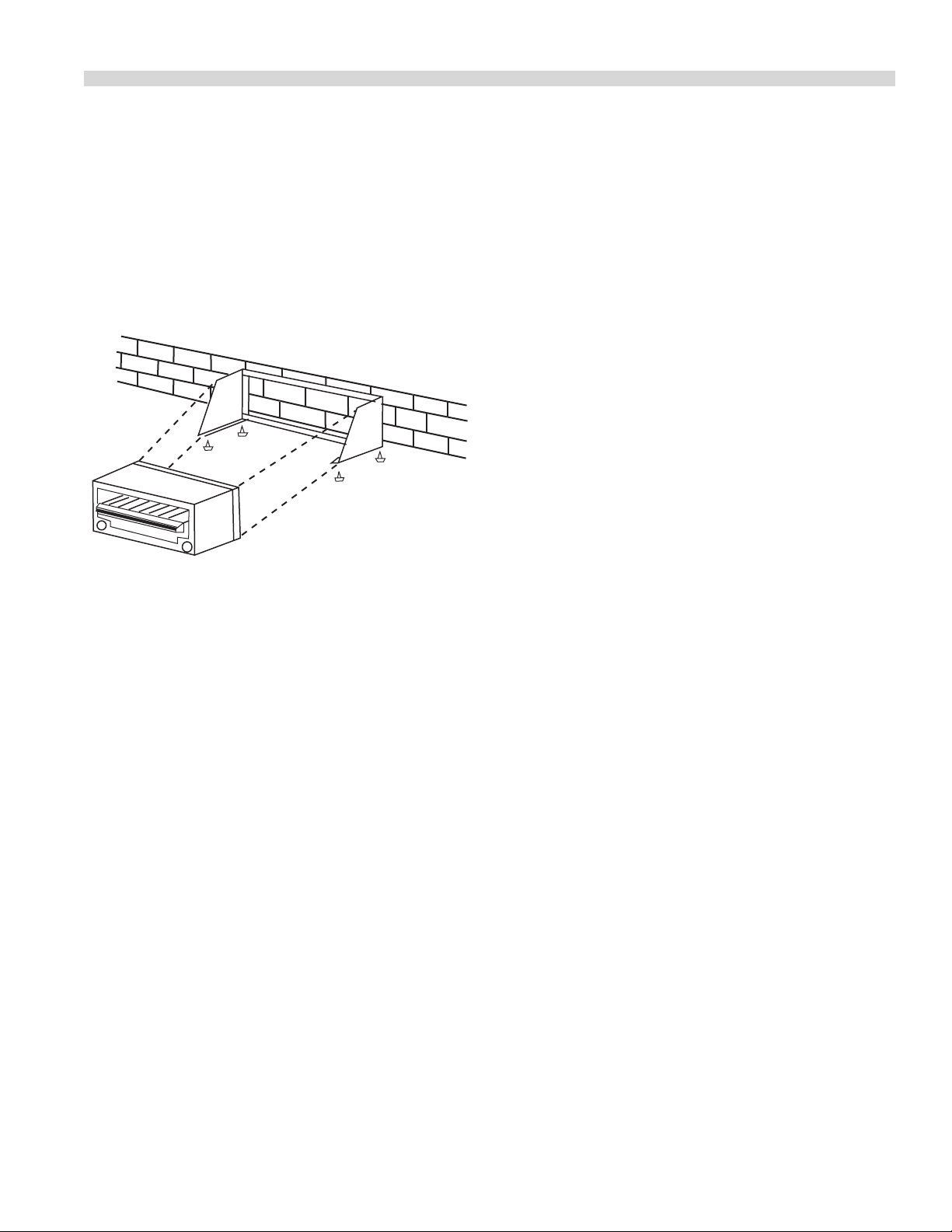
Wall Mounting
1. If the unit is to be mounted on a non-combustible wall
contact the local building department for local codes.
2. Each gas appliance must be located with respect to
building construction and other equipment so as to
permit access to the appliance, Such access and clearance
may be necessary for servicing and cleaning.
3. Salamanders intended for wall mounting are shipped
with the mounting kit already attached.
4. Provisions for gas connections, bottom or rear should be
taken into consideration.
. Position, level, and mark location of assembled wall
mount kit.
Part # Rev 3 1844033 (02/22/08)Page 4
Page 5
Part # Rev 3 1844033 (02/22/08) Page 5
INSTALLATION Continued
. Drill wall (locating wall studs if necessary) to accept
suitable fastening devices.
. Drill angle iron bars of wall mounting kit to match holes
drilled in wall.
. Install wall mounting kit to wall.
. Install and secure broiler with bolts supplied.
Range Mounting
Salamanders my not be mounted onto an already existing
high shelf or high riser with out internally bracing the vertical
panel. The back sheet of a range is not designed to carry that
much weight, and the outside body panels of a salamander
intended for wall mounting are dierent. It is important that
the factory be notied at the time of order/purchase that
the salamander is intended for range mount retrot. Range
mounted Salamanders are normally mounted at the factory
during manufacture.
A salamander intended for eld installation onto an existing
high shelf or high riser will be delivered with two pieces
of at bar steel, each of which has one end bent into a tab.
Install in the fallowing sequence.
1. Slide the at bars into the ue of the high riser (or shelf)
ush to the outside ends with the tabs facing to the
center.
2. Secure these stieners to the sides of the ue with bolts
or heavy self-tapping screws, with the top of the stiener
extending 18” (457mm) above the shelf or 16” (406mm)
above the top of the high riser.
3. Slide the Salamander down over the at bars and secure
with bolts from the at bar tab onto the Salamander.
Counter Installation
Salamanders intended for counter use are manufactured
with leg couplings in the bottom corners and are furnished
with 4” (102mm) legs. Units are not to be installed without
the legs, as the bottom clearance is necessary for heat
dissipation. Level the unit with a carpenter’s level, using the
screw thread of the legs for minor adjustments.
Air Supply and Ventilation
The area around the appliance must be kept clear to avoid
any obstruction to the ow of combustion and ventilation
air, as well as, for ease of maintenance and service. Under
no conditions should anything be stored on top or over the
Salamander, as ue gas temperatures are in the vicinity of
500°-700°F (260°-371°C).
Means must be provided for any commercial, heavy-duty
cooking appliance to exhaust combustion waste products to
the outside of the building. Usual practice is to place the unit
under an exhaust hood; the minimum should be an exhaust
fan mounted above the unit. Filters and drip troughs should
be part of any industrial hood, but consult local codes before
constructing and installing a hood.
Strong exhaust fans in this hood or in the overall air
conditioning system can produce a slight vacuum in the
room and/or cause air drafts, either of which can interfere
with pilot or burner performance and be hard to diagnose.
Air movement should be checked during installation; if
pilot/burner outage problems persist make-up air openings
or baes may have to be provided in the room.
Gas Supply
1. Installation of the equipment should be made by a
licensed plumber.
2. A gas shut-o valve must be installed in the gas supply
line ahead or the appliance for safety and for ease of
future service.
3. A gas pressure regulator must be installed at the
appliance prior to connecting the equipment to the gas
line. Failure to install a regulator will void the equipment
warranty.
NOTE: The gas supply (service) line must be the same size
or greater than the inlet line of the appliance. U.S. Range
Salamander use a 3/4” NPT inlet. Sealant on all pipe joints
must be resistive to LP gas.
Page 6

INSTALLATION Continued
National Code Requirements
Safe and satisfactory operation of your equipment depends,
to a great extent, on its proper installation. Installation must
conform to local codes or, in the absence of local codes with
the National Fuel code, ANSI Z223.1, Natural Gas Installation
Code, CAN/CGA-B149.1, or the Propane Installation Code,
CAN/CGA-B149.2, as applicable, including:
1. The appliance and its individual shuto valve must be
disconnected from the gas supply piping system during
any pressure testing of that system at test pressures in
excess of 1/2 psi (3.45 kPa).
2. The appliance must be isolated from the gas supply
piping system by closing its individual manual shuto
valve during any pressure testing of the gas supply piping
system at test pressures equal to or less than 1/2 psi
(3.45 kPa)
Manual Shut-O Valve
This installer-supplied valve must be installed in the gas
service line ahead of the appliance and regulator in the gas
stream and in a position where it can be reached quickly
in the event of an emergency. If the Salamander is ranged
mounted, a separate shut-o valve should be on the line to
the unit.
Pressure Regulator
All heavy-duty, commercial cooking equipment must have
a pressure regulator in the incoming service line for safe and
ecient operation, since service pressure may uctuate with
local demand. The manual shut-o valve is normally supplied
by the installer, but pressure regulators are shipped from U.S.
Range with every hot plate.
Regulators are pre-set at the factory for 5” WC (natural gas)
or 10” WC (propane) according to the customer’s ordering
instructions.
Prior to connecting the regulator, check the incoming line
pressure, as these regulators can withstand a maximum
pressure of 1/2 psi (14” WC). If the Line pressure is beyond
this limit, a step-down regulator will be required. Doublecheck the arrow forged onto the bottom of the regulator
body which shows gas ow directions; it should point
downstream to the appliance. The red air-vent cap is part of
the regulator and should not be removed unless local codes
require external venting.
Regulators can be adjusted in the eld, but it is
recommended that they not be tampered with unless that
part is known to be out of adjustment or serious pressure
uctuations are found to exist and can be solved no other
way. Any adjustments to regulators must be made by
qualied service personnel with proper test equipment.
WARNING Do not connect the regulator inside the unit’s
body or directly on top of the salamander, as temperatures
are high enough in these areas to destroy the regulator.
Failure to install a pressure regulator will void the
equipment warranty!
Rigid Connections
Double-check any installer-supplied intake pipes visually
and clear any dirt particles, threading chips, or other foreign
matter before installing in a service line. Those particles will
clog orices when gas pressure is applied.
WARNING All connections must be sealed with a joint
compound suitable for LP gas, and all connections must be
tested with a soapy solution before lighting any pilots!
Flexible Couplings & Connectors.
If the unit is to be installed with exible couplings and/or
quick-disconnect ttings, for an appliance equipped with
casters, the installation shall be made with a connector that
complies with the Standard for Connectors for Movable Gas
Appliances, ANSI Z21.69 /CSA 6.16, and a quick-disconnect
device that complies with the Standard for Quick-Disconnect
Devices for Use With Gas Fuel, ANSI Z21.41 / CSA 6.9, and
adequate means must be provided to limit the movement
of the appliance without depending on the connector and
the quick-disconnect device or its associated piping to limit
the appliance movement and the location(s) where the
restraining means may be attached to the appliance shall be
specied.
Further, if the unit is to be installed on a non-combustible
surface that is equipped with casters, means must be
provided to limit the movement of the unit on this surface.
Manual Pilot Valve
Part # Rev 3 1844033 (02/22/08)Page 6
Page 7

Part # Rev 3 1844033 (02/22/08) Page 7
INSTALLATION Continued
All burners are equipped with constant-burning pilots. These
should be manually lighted immediately after the gas is
turned on and the system is checked for leaks. An adjustment
screw for each pilot is located on the gas manifold and can
be accessed through openings in the valve panel between
the valve knobs.
Testing and Adjustments
Check all gas connections for leaks using a soapy solution
before lighting any pilots. DO NOT USE OPEN FLAME
TO CHECK FOR LEAKS! Putting open ame beside a new
connection is not only dangerous, but will often miss small
leaks that a soapy solution would nd.
All U.S. Range appliances are adjusted and tested before
leaving the factory, eectively matching them to sea
level conditions. Adjustments and calibrations to assure
proper operation may be necessary on installation to meet
local conditions, low gas pressure, dierences in altitude;
variations in gas characteristics, to correct possible problems
caused by rough handling or vibration during shipment, and
are to be performed only by qualied service personnel.
These adjustments are the responsibility of the customer,
installer and/or dealer and are not covered by the U.S. Range
warranty.
Page 8

INITIAL OPERATION
Initial Pilot Light
Initial pilot light is in the following sequence:
1. Turn the manual shut-o valve on the incoming service
line “OFF”.
2. Turn all burner valves “OFF”.
3. Close all pilot adjusting screws (clockwise turn all the
way in).
4. Wait for any accumulated gas to disperse.
5. Open the manual shut-o valve.
6. Apply a lighted match or taper to a pilot burner and open
that pilot’s adjustment screw gradually until the pilot
lights.
7. Adjust the pilot ame for the desired characteristics.
8. Turn “ON” that main burner and watch to make sure it
lights from the pilot, then turn the burner “OFF”.
9. Repeat steps 6 through 8 to light all remaining pilots.
If only one pilot has gone out, it is not necessary to follow
the entire procedure outlined above. Merely apply a lighted
match or taper to the pilot until it lights, then adjust the pilot
valve. If the pilot will not light, close the adjustment valve
completely, do not use that burner, and call for service.
NOTE: It may be necessary to re-light the pilots several
times until the new lines are purged of any trapped air and
constant gas ow is attained.
WARNING
The tiles on the face of an infrared burner are porous and
extremely delicate when hot. If these tiles are bumped
roughly with normal hand tools, they can easily crack,
destroying the eectiveness of the burner. The only repair
to a cracked tile is to replace the entire burner.
Final Preparation
New units are wiped clean with solvent at the factory to
remove any visible signs of dirt, oil, grease, etc., remaining
from the manufacturing process. They should be washed
with hot, soapy water to remove any solvent or oil residue or
installation dust or debris before using for food preparation.
A “J” hook reaching to the rear is built into the carriage
assembly, which supports the cast iron broiling grates. This
hook normally catches onto the front cross bar connecting
the right and left-hand grid runners. When the Salamander
is packed for shipment this “J” hook is latched onto the rear
connecting cross bar to limit accidental travel of the carriage.
This can be seen only with the grates removed.
Lift the “J” hook and cautiously slide the carriage out a few
inches, then let the hook drip. Slide the carriage the rest of
the way out and make sure the “J” hook catches on the front
cross bar. If this is not done, the carriage will move only
about two or three inches; if the “J” hook misses the front bar,
the carriage assembly will slide completely out.
Part # Rev 3 1844033 (02/22/08)Page 8
Page 9

Part # Rev 3 1844033 (02/22/08) Page 9
CLEANING AND MAINTENANCE
WARNING If gas odors are detected, the gas supply must
be turned “OFF’ at the main shut-o valve and the local
gas company or authorized service agency contacted for
service.
General Cleaning
Any piece of equipment works better and lasts longer when
maintained properly and kept clean. Cooking equipment is
no exception. Your U.S. Range hot plate must be kept clean
during the working day and thoroughly cleaned at the end
of each day.
Daily
1. Remove the broiler grates. Wire brush them clean of any
encrusted materials and wash in hot, soapy water.
2. The drip pan should be cleaned regularly in the course
of the working day, wiping up spills as they occur. At the
end of the day, remove the pan and wash in hot, soapy
water.
3. Wash the reminder of the Salamander’s interior while the
drip pan and grates are removed, then reassemble.
4. Wipe the outside of the Salamander’s body.
CAUTION The drawer assembly is spring loaded to carry
the eight of the carriage and grates. If the handle is released
without the grates on the carriage, the carriage will slam to
the “UP” position.
Periodic
Your U.S. Range Salamander should be checked and adjusted
periodically by qualied service personnel as part of a regular
kitchen maintenance program.
Cleaning Stainless Steel
All stainless steel body parts should be wiped regularly with
hot, soapy water during the day, and with a liquid cleaner
designed for this material at the end of each day. Do not
use steel wool, abrasive cloths, cleansers, or powders! If it
is necessary to scrape stainless steel to remove encrusted
materials, soak the encrusted area with wet cloths to loosen
the material, then use a wood or nylon scraper. Do not use
a metal knife, spatula, or any other metal tools to scrape
stainless steel. Scratches are almost impossible to remove.
SERVICE AND PARTS
Installation, maintenance and repairs should be performed
by your local authorized U.S. Range service agency listed in
your information manual pamphlet.
Page 10

Page 11

Page 12

Pièce n° Rev 3 1844033 (02/22/08) Page 9
sur la liste du manuel.
par l’agence de service locale autorisée U.S. Range, gurant
L’installation, l’entretien et les réparations doivent être faits
SERVICE ET PIECES DE RECHANGE
rayures sont presque impossibles à retirer.
autre outil métallique pour gratter l’acier ixodydable. Les
N’utilisez pas de couteau ni de spatule en métal ni aucun
décoller et utilisez ensuite un grattoir en bois ou en nylon.
trempez le produit incrusté avec un chi on mouillé pour le
gratter l’acier inoxydable pour retirer des produits incrustés,
abrasifs ni de poudres de nettoyage! S’il est nécessaire de
n de chaque journée. N’utilisez pas de laine d’acier, de tissus
journée et avec un produit de nettoyage liquide spécial à la
régulièrement avec de l’eau chaude savonneuse pendant la
Toutes les pièces en acier inoxydable devront être lavées
Nettoyage De L’acier Inoxydable
cuisine.
dans le cadre d’un programme d’entretien régulier de la
réglée périodiquement par du personnel d’entretien quali é
Votre gril à Salamandre U.S. Range devra être véri ée et
Périodique
position “UP”.
lâchée sans les grilles sur le chariot, le chariot va se fermer en
supporter le poids du chariot et des grilles. Si la poignée est
ATTENTION : L’ensemble de tiroir est muni d’un ressort pour
4. Essuyer l’extérieur de la carrosserie de la salamandre.
place.
lèchefrites et les grilles sont enlevées, puis les remettre en
3. Laver le reste de l’intérieur de la salamandre lorsque les
et la laver à l’eau savonneuse chaude.
se produisent. À la n de la journée, enlever la lèchefrite
journée de travail et les déversements essuyés dès qu’ils
2. La lèchefrite doit être régulièrement nettoyée durant la
laver dans l’eau savonneuse chaude.
métallique pour en enlever tout aliment incrusté. Les
1. Enlever les grilles du gril. Les nettoyer à la brosse
Quotidien
jour.
journée de travail et être nettoyée à fond à la n de chaque
Salamandre U.S. Range doit être maintenue propre durant la
L’équipement de cuisson ne fait pas exception. Votre gril à
s’il est correctement entretenu et maintenu propre.
Tout équipement fonctionne mieux et dure plus longtemps
Nettoyage Général
ou un service de réparation autorisé.
principal et l’on doit contacter la compagne locale de gaz
l’alimentation en gaz doit être coupée au robinet d’arrêt
AVERTISSEMENT : Si l’on détecte une odeur de gaz,
NETTOYAGE ET ENTRETIEN
Page 13

Pièce n° Rev 3 1844033 (02/22/08)Page 8
complètement à l’extérieur.
ne s’engage pas dans la barre transversale, le chariot sortira
déplacera que de deux ou trois pouces. Si le crochet en “J”
transversale avant. Si ce n’est pas le cas, le chariot ne se
et s’assurer que le crochet en “J” s’engage dans la barre
crochet. Tirer sur toute sa course le chariot vers l’extérieur
vers l’extérieur de quelques pouces, puis laisser tomber le
Soulever le crochet en “J” et faire doucement glisser le chariot
fois les grilles enlevées.
déplacement accidentel du chariot. On ne peut le voir qu’une
en “J” est xé à la barre transversale arrière pour limiter tout
de l’emballage de la salamandre pour l’expédition, ce crochet
avant reliant les coulisseaux gauche et droit des grilles. Lors
crochet s’engage normalement dans la barre transversale
l’ensemble de chariot, qui soutient les grilles en fonte. Ce
Un crochet en “J” orienté vers l’arrière est intégré dans
cuisson d’aliments.
d’huile et de solvant ou les débris avant de les utiliser pour la
être lavés à l’eau chaude savonneuse pour retirer les résidus
etc., restant du processus de fabrication. Ils devront donc
pour éliminer toute trace visible de saleté, d’huile, de graisse,
Les appareils neufs sont nettoyés avec du solvant en usine
réparateur.
soupape de réglage, n’utilisez pas ce brûleur et appelez le
Si la veilleuse ne s’allume pas, fermez complètement la
la veilleuse jusqu’à ce qu’elle s’allume, puis réglez la veilleuse.
simplement une allumette ou une mèche en ammée près de
suivre toute la procédure indiquée ci-dessus. Appliquez
Si une seule veilleuse s’est éteint, il est nécessaire de
restantes.
9. Répéter les étapes 6 à 8 pour allumer toutes les veilleuses
bout d’environ trente secondes.
être di cile à voir, mais qui deviendra rouge cerise au
début, le brûleur brûle avec une amme bleue qui peut
brûleur s’allume par la veilleuse, puis arrêter le brûleur. Au
8. Mettre le brûleur infrarouge sur “ON” et s’assurer que le
souhaitées.
7. Régler la amme de veilleuse pour les caractéristiques
réglage de cette veilleuse jusqu’à ce qu’elle s’allume.
brûleur infrarouge) et ouvrez progressivement la vis de
xée sur le côté de l’appareil, juste dessous et à droite du
veilleuse (ceci est monté sur une languette fabriquée,
6. Appliquez une allumette ou une mèche près d’une
Préparation Finale
5. Ouvrez le robinet d’arrêt manuel.
un carreau ssuré est de remplacer tout le brûleur.
annulera l’e cacité du brûleur. La seule façon de réparer
de cuisine, elles peuvent se ssurer facilement, ce qui
chaudes. Si ces carreaux subissent le choc d’un ustensile
poreuses et extrêmement fragiles lorsqu’elles sont
Les carreaux de la façade du brûleur à infrarouge sont
4. Attendez que le gaz accumulé se disperse.
vissant complètement à droite).
3. Fermez toutes les vis de réglage des veilleuses (en les
2. Fermez tous les robinets de brûleurs.
AVERTISSEMENT
gaz constant.
purgées de toute trace d’air et qu’on obtienne une débit de
plusieurs fois jusqu’à ce que les nouvelles conduites soient
NOTA : Il peut être nécessaire de réallumer les veilleuses
d’alimentation en gaz.
1. Fermez le robinet d’arrêt manuel sur la conduite
Procédez à l’allumage des veilleuses dans l’ordre suivant :
Allumage Initial Des Veilleuses
UTILISATION INITIALE
Page 14

Pièce n° Rev 3 1844033 (02/22/08) Page 7
la garanties U.S. Range.
l’installateur et/ou du revendeur et ne sont pas couverts par
Ces réglages sont de la responsabilité du client, de
e ectués par du personnel d’entretien quali é.
ou des vibrations pendant le transport, et ils doivent être
du gaz, a n de corriger des problèmes causés par des chocs
di érences d’altitude, aux variations des caractéristiques
aux conditions locales, à une faible pression du gaz, aux
peuvent être nécessaire lors de l’installation pour répondre
réglages et étalonnages pour fonctionner correctement
quitter l’usine, pour correspondre au niveau de la mer. Des
Tous les appareils U.S. Range sont réglés et testés avant de
que l’eau savonneuse pourrait détecter.
dangereux, mais on manquera souvent ainsi de petites fuites
nue près d’une nouvelle connexion est non seulement
LA PRÉSENCE DE FUITES! Le fait de placer une amme
veilleuses. N’UTILISEZ PAS DE FLAMME NUE POUR VÉRIFIER
en utilisant une solution savonneuse avant d’allumer les
Véri ez toutes les connexions du gaz pour déceler les fuites
robinets entre les boutons.
peut y accéder par les ouvertures dans le panneau des
chaque veilleuse est situé dans le collecteur de gaz et on
système comportait des fuites. Une vis de réglage pour
immédiatement après avoir ouvert le gaz et véri é si le
constante. Elles devront être allumées manuellement
Tous les brûleurs sont équipés de veilleuses à amme
Robinet Manuel De Veilleuse
surface.
prévus pour limiter les déplacements de l’appareil sur cette
combustible équipée de roulettes., des moyens doivent être
De plus, si l’appareil doit être installé sur une surface non
l’appareils seront spéci és.
emplacements où les moyens de retenue peuvent être xés à
connexe pour limiter les déplacements de l’appareil et les
et le dispositif de débranchement rapide ou sa tuyauterie
le déplacement de l’appareil sans utiliser le connecteur
ANSI Z21.41 / CSA 6.9, et un dispositif sera prévu pour limiter
pour les Dispositifs à débranchement rapide pour le gaz,
dispositif de débranchement rapide conforme à la norme
pour appareils mobiles, ANSI Z21.69 / CSA 6.16, et un
connecteur conformément à la norme pour connecteurs
équipés de roulettes, l’installation doit être faite avec un
exibles et/ou des raccords rapides pour les appareils
Si l’unité doit être installée avec des accouplements
Essais Et Réglages
Raccords Et Connecteurs Souples
INSTALLATION suite
Page 15

Pièce n° Rev 3 1844033 (02/22/08)Page 6
savonneuse avant d’allumer les vielleuses!
le GPL et toutes connexions doivent être testées à l’eau
étanchéi ées, avec un composé à joint convenable pour
AVERTISSEMENT : Toutes les connexions doivent être
boucheront les ori ces une fois la pression de gaz appliquée.
d’installer une conduite d’alimentation. Ces particules
copeaux de letage et autres matières étrangères avant
par l’installateur et nettoyez toutes les particules de saleté,
Véri ez bien visuellement les tuyaux d’alimentation fournis
Connexions Rigides
annulera la garantie de l’équipement!
le régulateur. Toute absence de régulateur de pression
su samment élevées dans ces endroits pour détruire
la Salamandre étant donné que les températures sont
l’intérieur de l’appareil ou directement au-dessus de
AVERTISSEMENT : Ne branchez pas le régulateur à
l’équipement d’essai approprié.
doit être e ectué par du personnel d’entretien quali é avec
être résolu d’une autre façon. Tout réglage du régulateur
uctuations de pression et que le problème ne puisse pas
que le régulateur est déréglé ou qu’il existe d’importantes
recommandé de ne pas les modi er à moins que l’on sache
Les régulateurs peuvent être ajustés sur place, mais il est
une mise à l’air libre extérieure.
ne devra pas être retiré à moins que les codes locaux exigent
Le bouchon d’évent d’air rouge fait partie du régulateur et
sens du débit du gaz; elle devra être orientée vers l’appareil.
bien la èche forgée sur le corps du régulateur qui montre le
régulateur abaissseur de pression sera nécessaire. Véri ez
pression de la conduite est supérieure à cette limite, un
à une pression maximale de 0,5 lb/po2 (14 po C.E.). Si la
du gaz, étant donné que ces régulateurs peuvent résister
Avant de brancher le régulateur, véri ez la pression d’arrivée
conduite de gaz à l’appareil.
unité autonome, prévoir une soupape d’arrêt séparée sur la
facilement en cas d’urgence. Si la salamandre est montée en
régulateur de pression, à un endroit où on peut l’atteindre
la conduite d’alimentation en gaz avant l’appareil et le
Le robinet fourni par l’installateur doit être monté sur
Robinet D’arrêt Manuel
inférieures à 0,5 lb/po2 (3,45 kPa).
essai de pression du système à des pressions égales ou
gaz en fermant son robinet d’arrêt individuel lors de tout
2. L’appareil doit être isolé du système d’alimentation en
(3,45 kPa).
pression du système à des pressions dépassant 0,5 lb/po2
débranchés de l’alimentation en gaz lors de tout essai de
1. L’appareil et son robinet d’arrêt individuel doivent être
y compris :
Code d’installation du propane CAN/CGA-B149.2, selon le cas,
Code d’installation du gaz naturel, CAN/CGA-B149.1 ou au
l’absence de codes locaux, au National Fuel code, ANSI Z223.1,
L’installation doit être conforme aux codes locaux ou, en
dépend, dans une grande mesure, de son installation correcte.
Le fonctionnement sécuritaire et satisfaisant de l’équipement
Exigences Des Codes Nationaux
appliqué sur tous les raccords doivent résister au GPL.
utilisent une entrée 3/4 po NPT. Le produit d’étanchéité
d’entrée de l’appareil. Des grils U.S. Range à Salamandre
diamètre ou d’un diamètre supérieur à celui de la conduite
NOTA : La conduite d’alimentation de gaz doit être du même
du client.
naturel) ou 10 po C.E. (propane) en fonction de la commande
Les régulateurs sont préréglés en usine pour 5 po C.E. (gaz
expédiés par U.S. Range avec chaque Salamandre.
fourni par l’installateur, mais les régulateurs de pression sont
de la demande. Le robinet d’arrêt manuel est normalement
donné que la pression d’alimentation peut varier en fonction
en gaz pour un fonctionnement sécuritaire et e cace, étant
d’un régulateur de pression sur la conduite d’alimentation
Tout gros équipement de cuisson commercial doit être doté
Régulateur De Pression
l’équipement.
de gaz. L’absence de régulateur annulera la garantie sur
l’appareil avant de brancher l’équipement à la conduite
3. Un régulateur de pression du gaz doit être installé sur
sécurité et pour faciliter les réparations ultérieures.
conduite d’alimentation en amont de l’appareil pour la
2. Un robinet de fermeture du gaz doit être installé sur la
plombier licencié..
1. L’installation de l’équipement devra être faite par un
Alimentation En Gaz
INSTALLATION suite
Page 16

ouvertures ou dé ecteurs d’air dans la pièce.
brûleurs persistent, il est possible que l’on doive prévoir des
véri é lors de l’installation; si les problèmes de veilleuses/
di ciles à diagnostiquer. Tout mouvement d’air devra être
avec les performances des brûleurs ou des veilleuses et être
dans la pièce et/ou des courants d’air, qui peuvent interférer
le système d’air conditionné peuvent causer un léger vide
Des ventilateurs d’extraction puissants dans la hotte ou dans
les codes locaux avant de construire une hotte.
de ltres et d’ori ce d’écoulement, mais vous devez consulter
est un minimum. Toute hotte industrielle devrait être dotée
présence d’un ventilateur d’extraction au-dessus de l’appareil
On place généralement l’unité une hotte d’extraction; la
d’évacuer les produits de cuisson à l’extérieur du bâtiment.
Pour tout appareil de cuisson commercial, il est nécessaire
conduit de fumée est voisine de 500°-700°F (260°-371°C).
ou au dessus de la salamandre car la température des gaz du
réparations. En aucun cas, il ne faut rien poser sur le dessus
de ventilation, ainsi que pour faciliter l’entretien et les
éviter toute obstruction du ux d’air de combustion et
La zone autour de l’appareil doit être dégagée pour
Pièce n° Rev 3 1844033 (02/22/08) Page 5
fabrication.
sont normalement montées en usine au moment de la
autonome. Les salamandre montées en unités autonomes
achat que la salamandre est destinée à un montage en unité
important de noti er à l’usine au moment de la commande/
salamandre destinée au montage mural sont di érents . Il est
important et les panneaux de carrosserie extérieurs d’une
d’une cuisinière n’est pas conçue pour soutenir un poids
renforcer intérieurement le panneau vertical. La paroi arrière
étagères hautes ou des colonnes montantes existantes sans
Les salamandres ne doivent pas être montées sur des
Montage en unité autonome
Alimentation En Air Et Ventilation
charpentier et les vis des pieds pour le réglage.
faut mettre l’appareil de niveau en utilisant un niveau de
inférieur est nécessaire pour la dissipation de la chaleur. Il
doivent pas être installées sans les pieds, parce que l’espace
inférieurs et sont livrées avec des pieds de 4 po. Ces unités ne
sont fabriquées avec des supports de pieds dans les coins
Les salamandres destinées à être utilisées sur un comptoir
Installation Sur Comptoir
plat vers la salamandre.
et xer les boulons depuis la languette de la pièce d’acier
3. Faire glisser la salamandre vers le bas sur les barres plates
haut de la colonne montante.
dessus de l’étagère ou de 16 po (406 mm) au dessus du
dessus du raidisseur dépassant de 18 po (457 mm) au
des boulons ou de grosses vis autotaraudeuses, avec le
2. Fixer ces raidisseurs aux côtés du conduit de fumée avec
vers le centre.
avec les bords extérieurs, avec les languettes orientées
fumée de la colonne montante ou de l’étagère de niveau
1. Faire glisser les pièces d’acier plat dans le conduit de
languette. Procéder au montage dans l’ordre suivant :
pièces en acier plat ayant chacune une extrémité pliée en
ou une colonne montante existants seront livrées avec deux
Une salamandre destinée au montage sur une étagère haute
9. Installer et xer le grilloir avec des boulons fournis
8. Installer le nécessaire d’accrochage au mur sur le mur.
perforés dans le mur.
d’accrochage au mur pour correspondre aux trous
7. Perforer les barres de fer d’angle du nécessaire
appropriés.
nécessaire) pour accepter les dispositifs d’attache
6. Perforer le mur (en localisant des goujons de mur si
nécessaire d’accrochage au mur assemblé.
5. Position, niveau, et emplacement de la marque du
dessous ou de l’arrière devraient être prises en compte.
4. Des dispositions pour des raccordements du gaz, du
transportées avec le nécessaire d’accrochage déjà joint.
3. Des salamandres prévues pour l’accrochage au mur sont
entretenir et nettoyer.
tel accès et dégagement peuvent être nécessaires pour
équipements a n de permettre l’accès à l’appareil. Un
respectant la construction de bâtiments et d’autres
2. Chaque appareil d’utilisation du gaz doit être situé en
INSTALLATION suite
Page 17

Pièce n° Rev 3 1844033 (02/22/08)Page 4
pour des codes locaux.
contactez le service des bâtiments et de l’entretien local
1. Si l’unité doit être montée sur un mur non combustible
Accrochage au Mur
Côtés 0 po
Arrière 0 po
combustible:
Construction non-
(304 mm)
12 po
(152 mm)
6 po
Dégagement minimum
Type de construction
Positionnement Et Installation
Côtés
Arrière
Construction combustible:
combustibles uniquement.
2. Pour une utilisation dans des emplacements non
1. Pour une utilisation autre que ménagère
installations suivantes ;
Ces appareils sont homologués par conception pour les
combustibles.
L’appareil doit être tenu à l’écart de tous les produits
Dégagements
INSTALLATION
l’American national Standards Institute, Inc.
conforme à la norme ANSI 283.11 (dernière édition) de
identi é sur la plaque signalétique ! L’installation doit être
Range doivent être branchées uniquement au type de gaz
AVERTISSEMENT : Toutes les rôtissoires salamandre U.S.
ou le propane.
de sortie de gaz en pouces C.E. et ori ces pour le gaz naturel
suivantes : débit calori que des brûleurs en BTU/h, pression
Les autres informations gurant sur cette plaque sont les
signalétique xée à l’appareil contient ces renseignements.
et du su xe) et le numéro de série de garantie. La plaque
modèle correct (comprenant les lettres et chi res du pré xe
rechange, bien faire référence à l’appareil avec le numéro de
local concernant des problèmes de service ou des pièces de
Pour correspondre avec l’usine ou le centre de service agréé
transport appropriées.
contacter l’expéditeur et remplir les réclamations de
En cas de dommages, ne pas refuser l’expédition, mais
dommages dus au transport sur l’équipement.
Après le déballage, véri er immédiatement les signes de
Déballage
par le concessionnaire ou une agence de services quali ée.
recommandé de faire e ectuer des inspections périodiques
L’appareil doit être nettoyé et entretenu régulièrement. Il est
chaque extrémité).
est accessible après avoir retiré cette garniture (deux vis à
derrière la garniture supérieure en acier inoxydable. Elle
La plaque signalétique est xée au corps de la salamandre,
Plaque Signalétique
usine avant l’expédition.
à la sole de la rôtissoire. Tous les appareils sont inspectés en
rôtissoire. Ces articles sont emballés individuellement et xés
emballés à l’intérieur de l’appareil avec les grilles de la
les clips de montage mural et les régulateurs de pression
Tous les appareils sont expédiés complètement montés, avec
INTRODUCTION
Page 18

Pièce n° Rev 3 1844033 (02/22/08) Page 3
SERVICE ET PIECES DE RECHANGE . . . . . . . . . . . . . . . . . . . . . . . . . . . . . . . . . . . 9
Nettoyage De L’acier Inoxydable . . . . . . . . . . . . . . . . . . . . . . . . . . . . . . . . . . . . . . . . . . . . . . . . . .9
Nettoyage Général . . . . . . . . . . . . . . . . . . . . . . . . . . . . . . . . . . . . . . . . . . . . . . . . . . . . . . . . . . . . . . .9
NETTOYAGE ET ENTRETIEN . . . . . . . . . . . . . . . . . . . . . . . . . . . . . . . . . . . . . . . . . . 9
Préparation Finale . . . . . . . . . . . . . . . . . . . . . . . . . . . . . . . . . . . . . . . . . . . . . . . . . . . . . . . . . . . . . . .8
Allumage Initial Des Veilleuses . . . . . . . . . . . . . . . . . . . . . . . . . . . . . . . . . . . . . . . . . . . . . . . . . . .8
UTILISATION INITIALE . . . . . . . . . . . . . . . . . . . . . . . . . . . . . . . . . . . . . . . . . . . . . . . 8
Essais Et Réglages . . . . . . . . . . . . . . . . . . . . . . . . . . . . . . . . . . . . . . . . . . . . . . . . . . . . . . . . . . . . . . . .7
Robinet Manuel De Veilleuse . . . . . . . . . . . . . . . . . . . . . . . . . . . . . . . . . . . . . . . . . . . . . . . . . . . . .7
Raccords Et Connecteurs Souples . . . . . . . . . . . . . . . . . . . . . . . . . . . . . . . . . . . . . . . . . . . . . . . .7
Connexions Rigides . . . . . . . . . . . . . . . . . . . . . . . . . . . . . . . . . . . . . . . . . . . . . . . . . . . . . . . . . . . . .6
Régulateur De Pression . . . . . . . . . . . . . . . . . . . . . . . . . . . . . . . . . . . . . . . . . . . . . . . . . . . . . . . . . .6
Robinet D’arrêt Manuel . . . . . . . . . . . . . . . . . . . . . . . . . . . . . . . . . . . . . . . . . . . . . . . . . . . . . . . . . .6
Exigences Des Codes Nationaux . . . . . . . . . . . . . . . . . . . . . . . . . . . . . . . . . . . . . . . . . . . . . . . . . .6
Alimentation En Gaz . . . . . . . . . . . . . . . . . . . . . . . . . . . . . . . . . . . . . . . . . . . . . . . . . . . . . . . . . . . . .6
Alimentation En Air Et Ventilation . . . . . . . . . . . . . . . . . . . . . . . . . . . . . . . . . . . . . . . . . . . . . . . . .5
Installation Sur Comptoir . . . . . . . . . . . . . . . . . . . . . . . . . . . . . . . . . . . . . . . . . . . . . . . . . . . . . 5
Montage en unité autonome . . . . . . . . . . . . . . . . . . . . . . . . . . . . . . . . . . . . . . . . . . . . . . . . . 5
Accrochage au Mur . . . . . . . . . . . . . . . . . . . . . . . . . . . . . . . . . . . . . . . . . . . . . . . . . . . . . . . . . . 4
Positionnement Et Installation . . . . . . . . . . . . . . . . . . . . . . . . . . . . . . . . . . . . . . . . . . . . . . . . . . . .4
Dégagements . . . . . . . . . . . . . . . . . . . . . . . . . . . . . . . . . . . . . . . . . . . . . . . . . . . . . . . . . . . . . . . . . . .4
INSTALLATION . . . . . . . . . . . . . . . . . . . . . . . . . . . . . . . . . . . . . . . . . . . . . . . . . . . . . . 4
Plaque Signalétique . . . . . . . . . . . . . . . . . . . . . . . . . . . . . . . . . . . . . . . . . . . . . . . . . . . . . . . . . . . . .4
Déballage . . . . . . . . . . . . . . . . . . . . . . . . . . . . . . . . . . . . . . . . . . . . . . . . . . . . . . . . . . . . . . . . . . . . . . . 4
INTRODUCTION. . . . . . . . . . . . . . . . . . . . . . . . . . . . . . . . . . . . . . . . . . . . . . . . . . . . . 4
INFORMATIONS IMPORTANTES . . . . . . . . . . . . . . . . . . . . . . . . . . . . . . . . . . . . . . 2
TABLE DES MATIÈRES
Page 19

Pièce n° Rev 3 1844033 (02/22/08)Page 2
AVERTISSEMENT
dégagés et ne pas y stocker de produits combustibles
Maintenir les abords de l’appareil
d’autres problèmes reproductifs.
est reconnue par l’état de Californie comme pouvant causer des malformations congénitales ou
exposer au monoxyde de carbone en cas de mauvais réglage. L’inhalation de monoxyde de carbone
est reconnue par l’état de Californie comme causant le cancer. L’utilisation de ce produit peut vous
verre/fibres céramiques. L’inhalation de ces particules de laine de verre ou de fibres céramiques
L’installation et l’entretien de ce produit peut vous exposer aux poussières de laine de
le cancer et/ou des malformations congénitales ou d’autres problèmes de reproduction.
Ce produit contient des produits chimiques reconnus par l’état de Californie comme causant
INFORMATIONS IMPORTANTES
Page 20

Pièce n° Rev 3 1844033 (02/22/08) Page 1
Pièce nº 1844033 Rev 3 (02/22/08) © 2004 Garland Commercial Industries, Inc.
Télécopieur : 081-848-0041
Téléphone : 081-561-0433
ANGLETERRE
Swallow eld Way, Hayes, Middlesex UB3 1DQ
Enodis UK LTD.
.
être obtenue auprès du fournisseur de gaz local
détectée par l’utilisateur. Cette information peut
instructions à suivre en cas d’odeur de gaz
Placer dans un endroit bien en vue les
Pour votre sécurité
D’AUTORISATION : G-1-07-05-28
MONTEUR D’INSTALLATION AU GAZ. NUMÉRO
DOIT ÊTRE INSTALLÉ PAR UN PLOMBIER OU UN
DANS L’ÉTAT DU MASSACHUSETTS, CE PRODUIT
Télécopieur : 905-624-5669
Téléphone : 905-624-0260
CANADA
1177 Kamato Road, Mississauga, Ontario L4W 1X4
GARLAND COMMERCIAL RANGES, LTD.
L’ÉQUIPEMENT.
AVANT D’INSTALLER OU DE RÉPARER
D’UTILISATION ET D’ENTRETIEN
MENT LES INSTRUCTIONS D’INSTALLATION,
SURES OU LA MORT. LIRE SOIGNEUSE-
DES DOMMAGES MATÉRIELS, DES BLES-
ENTRETIEN MAL FAITS PEUVENT CAUSER
MODIFICATIONS, DES RÉPARATIONS OU UN
UNE INSTALLATION, DES RÉGLAGES, DES
AVERTISSEMENT
Télécopieur : (570) 636-3903
Téléphone : (570) 636-1000
Freeland, Pennsylvanie 18224
185 East South Street
GARLAND COMMERCIAL INDUSTRIES
conception et les spéci cations des pièces) peuvent être remplacés ou modi és sans préavis.
de Garland à : http://www.garland-group.com. Les renseignements contenus dans le présent document (y compris la
ou par des agents d’entretien non autorisés. Pour obtenir la liste des agents de service autorisés, consulter le site web
numéro de série aurait été mutilé, oblitéré ou supprimé ou qui aurait été modi é ou réparé avec des pièces non autorisées
codes nationaux et locaux ou aux instructions d’installation fournies avec le produit ou n’importe quel produit dont le
en ce qui concerne n’importe quel produit mal installé, réglé, utilisé ou qui n’aurait pas été entretenu conformément aux
d’entretien autorisé par Garland utilisant des pièces de rechange d’origine Garland. Garland n’aura aucune obligation
L’attention des utilisateurs est attirée sur le fait que l’entretien et les réparations doivent être e ectués par un agent
PROFESSIONNEL TEL QUE SPÉCIFIÉ.
ET DOIT ÊTRE INSTALLÉ PAR DU PERSONNEL
QU’ÉQUIPEMENT PROFESSIONNEL DE CUISSON
CE PRODUIT A ÉTÉ HOMOLOGUÉ EN TANT
ULTÉRIEUREMENT.
MANUEL ET LE CONSERVER POUR S’Y REPORTER
APPAREIL OU DE TOUT AUTRE APPAREIL
INFLAMMABLES À PROXIMITÉ DE CET
OU D’AUTRES VAPEURS OU LIQUIDES
NE PAS STOCKER NI UTILISER D’ESSENCE
POUR VOTRE SÉCURIT:
LIRE TOUTES LES SECTIONS DU PRÉSENT
»
SÉRIE «REGAL
GRILS À SALAMANDRE
ET D’INSTALLATION
MANUEL D’UTILISATION
 Loading...