

Page 1
INSTALLATION INSTRUCTIONS
"REGAL" Series of
Stock Pot Stoves
All U.S. Range equipment is manufactured for use with the type of gas specified on the
rating plate and for installation in accordance with ANSI Z-223.1 (latest edition) of the
National Fuel Gas Code. Copies may be obtained from the American Gas Association,
1515 Wilson Blvd., Arlington, VA - 22209.
FOR YOUR SAFETY
Do not store or use gasoline or other flammable
vapors and liquids in the vicinity of this or any
other appliance.
Instructions to be followed in case the user smells gas are to be posted in a prominent location. This information shall be obtained by contacting the local gas company
or gas supplier.
PLEASE RETAIN THIS MANUAL FOR FUTURE REFERENCE.
Page 2
IMPORTANT
Safe and satisfactory operation of your equipment depends to a great
extent on its proper installation. Installation must conform to local codes or,
in the absence of local codes, with the National Fuel Code, ANSI Z-223.1-
1980 (or latest edit ion).
U.S. Range manufactures the "Regal" Stock Pot (SP-1845) in one size only, roughly 18" square.
This is a single-grate unit, fired by a pair of nested ring burners, which produce 45,000 BTU/hr. All stock
Pots are shipped completely assembled, with the pressure regulator and adjustable legs packed on the
drip pan. The burners are tied to their hangers to prevent vibration damage. All units are adjusted, tested
and inspected at the factory prior to shipment.
After uncrating, immediately check the equipment for visible signs of
shipping damage. If such damage has occurred, do not refuse shipment, but
contact the shipper and file the appropriate freight claims.
1
General
1. Installation of the equipment should be made by a licensed plumber.
2. A manual shut-off valve must be installed in the gas supply line ahead of the appliance in the gas
stream for safety and for ease of future service.
3. A gas pressure regulator must be installed at the appliance prior to connecting the equipment to the
gas supply line. Failure to install a regulator will void the equipment warranty.
Rating Plate
This is on the inside of the body side and is accessible after removing the burner
knobs and valve cover.
Information on this plate includes the model and serial numbers ... when
Page 3
communicating with the factory about a unit or requesting special parts or information, this data is
2
essential for proper identification. Other information on this plate is the BTU/hr output of the burners,
outlet gas pressure in inches WC, and whether orificed for natural or propane gas.
Clearances
The appliance area must be kept free and clear of all combustibles. This unit is design-certified for
the following installations:
1. For installation on combustible-type flooring; and
2. Adjacent to combustible walls with the following minimum clearances:
a) Side walls - six inches
b) Back wall - six inches
Mechanical
There is no mechanical installation required beyond levelling. Place a carpenter's spirit level left -toright on the landing ledge and also front-to-back on the center finger of the top grate. Level to the high
corner with the screw adjustment built into the foot of each leg.
Air Supply & Ventilation
The area around the appliance must be kept clear to avoid any obstruc tion to the flow of
combustion and ventilation air as well as for ease of maintenance and service.
Means must be provided for any commercial, heavy-duty cooking appliance to exhaust combustion
waste products to the outside of the building. Usual practice is to place the unit under an exhaust hood;
the minimum should be an exhaust fan mounted above the unit. Filters and drip troughs should be part
of any industrial hood, but consult local codes before constructing and installing a hood.
Strong exhaust fans in this hood or in the overall air conditioning system can produce a slight
vacuum in the room and/or cause air drafts, either of which can interfere with pilot or burner
performance and be hard to diagnose. Air movement should be cheeked during installation; if pilot or
Page 4
burner outage problems persist, make -up air openings or baffles may have to be provided in the
3
room.
Gas Connection
NOTE: The gas supply (service) line must be the same size or greater than the inlet line of the
appliance. "Regal" Stock Pots use a 3/4" NPT inlet. Sealant on all pipe joints must be
resistive to LP gas.
Manual Shut-off Valve
This installer-supplied valve must be installed in the gas service line ahead of the appliance and
regulator in the gas stream and in a position whe re it can be reached quickly in the event of an
emergency.
Pressure Regulator
All heavy-duty, commercial cooking equipment must have a pressure regulator on the incoming
service line for safe and efficient operation, since service pressure may fluctuate with local demand. The
manual shut-off valve is normally supplied by the installer, but pressure regulators are shipped from
U.S.Range with every "Regal" Stock Pot.
Failure to Install a pressure regulator will void the equipment warranty!
Regulators are pre-set at the factory for 5" WC (natural gas) or 10" WC (propane) according to the
customer's ordering instructions.
Prior to connecting the regulator, check the incoming line pressure, as these regulators can
withstand a maximum pressure of 1/2 psi (14"WC). If the line pressure is beyond this limit, a step-down
regulator will be required. Double-check the arrow forged into the bottom of the regulator body which
shows gas flow direction; it should point downstream to the appliance. The red air vent cap is part of the
regulator and should not be removed.
Regulators can be adjusted in the field, but it is recommended that they not be tampered with
unless the part is known to be out of adjustment or
Page 5
4
serious pressure fluctuations are found to exist and can be solved no other way. Any adjustments to
regulators must be made only by qualified service personnel with the proper test equipment.
Rigid Connections
Double-check any installer-supplied intake pipes visually and/or blow them out with compressed air
to clear any dirt particles, threading chips, or other foreign matter before installing in a service line.
Those particles will clog orifices when gas pressure is applied.
All connections must be sealed with a joint compound suitable for LP gas,
and all connections must be tested with a soapy solution before lighting any
pilots!
Flexible Couplings, Connectors, Casters
If the unit is to be installed with flexible couplings and/or quick-disconnect fittings, the installer must
use a heavy-duty, AGA design-certified conmercial flexible connector of at least 3/4" MPT (with suitable
strain reliefs) in compliance with ANSI Z-21.69-1979. Domestic connectors are not suitable!
If the unit is to be installed on casters, the same ANSI Standard applies and, in addition, some
means must be provided to limit the movement of the appliance without depending on the connectors or
associated piping.
Initial Pilot Light
Check all gas connections for leaks using a soapy solut ion before lighting any pilots. DO NOT USE
AN OPEN FLAME TO CHECK FOR LEAKS! Putting an open flame beside a new connection is not only
dangerous, but will often miss small leaks that a soapy solution would find.
All U.S. Range appliances are adjusted and tested before leaving the factory, effectively
matching them to sea level conditions. Adjustments and calibrations to assure proper
operations may be necessary on installation to meet local conditions, low gas pressure,
differences in altitude, variations in gas characteristics to correct possible problems caused by
rough handling or vibration during shipment, and are to be
Page 6
performed only by qualified service personnel with the proper test equipment. These are the
5
responsibility of the customer and/or dealer and are not covered by U.S. Range warranty.
Both burners of the ring burner pair are lighted from one constant-burni ng pilot. This should be
manually lighted immediately after the gas is turned on and the system checked for leaks. The pilot
burner is located be tween the two nested ring burners, at the right rear, and is reached from the top
through the burner grate. Adjustments are through the opening in the valve cover between the burner
valve knobs.
Initial pilot light is in the following sequence:
1. Turn the manual shut -off valve on the incoming service line "off".
2. Turn all burner valves "off".
3. Close all pilot adjusting screws (right -hand turn all the way in).
4. Wait for any accumulated gas to disperse.
5. Open the manual shut -off valve.
6. Apply a lighted match or taper to the pilot burner and open the pilot's adjustment screw gradually
until the pilot lights.
7. Adjust the pilot flame for the desired characteristics.
8. Turn on each burner individually and watch to make sure it lights from the pilot, then turn the
burner "off".
When relighting a pilot which has gone out, it is not necessary to follow the entire procedure
outlined above. Merely apply a lighted match or taper to the pilot until it lights, then adjust the pilot valve.
If the pilot will not light, close the adjustment valve completely, do not use the Stock Pot, and call for
service.
Note: It may be necessary to relight the pilots several times until the new lines are purged of any
trapped air and a constant gas flow is attained.
Final Preparation
New units are wiped clean with solvent at the factory to remove any visible signs of dirt, oil, grease,
etcetera remaining from the manufac -
Page 7
turing process, then given a light coat of mineral oil prior to crating. They should be washed with hot,
6
soapy water to remove any solvent or oil residue or installation dust or debris before using for food
preparation.
Cleaning & Maintenance
Any piece of equipment works better and lasts longer when maintained properly and kept clean.
Cooking equipment is no exception. Your "Regal" Stock Pot must be kept clean during the working day
and thoroughly cleaned at the end of each day.
Daily
1. Check the drip pan frequently during the day, wiping up spills as they occur and before they have a
chance to bake solid. Drain the pan as necessary during the day, but at least once (at the end of
the day). Wash in hot, soapy water.
2. Remove the burners and wash in hot , soapy water. Remove the outer burner first by lifting slightly
to clear the inner burner, sliding to the rear -to clear the burner valve orifice, then lifting out.
Remove the inner burner in the same manner.
Weekly
If daily maintenance is performed as recommended above, weekly maintenance will not be
required beyond the daily cleaning for the last day of the working week.
Periodic
The Stock Pot should be checked and adjusted regularly by qualified service personnel as part of
a regular kitchen maintenance program.
Stainless Steel
All stainless steel body parts should be wiped regularly with hot, soapy water during the day and
with a liquid cleaner designed for this material at the end of each day. Do not use steel wool, abrasive
cloths, cleansers, or powders! If it is necessary to scrape stainless steel to remove encrusted
materials, soak the encrusted area with hot, wet cloth to loosen the material, then use a wood or nylon
scraper. Do not use a metal knife, spatula, or any other metal tool to scrape stainless steel. Scratches
are almost impossible to remove.
Page 8
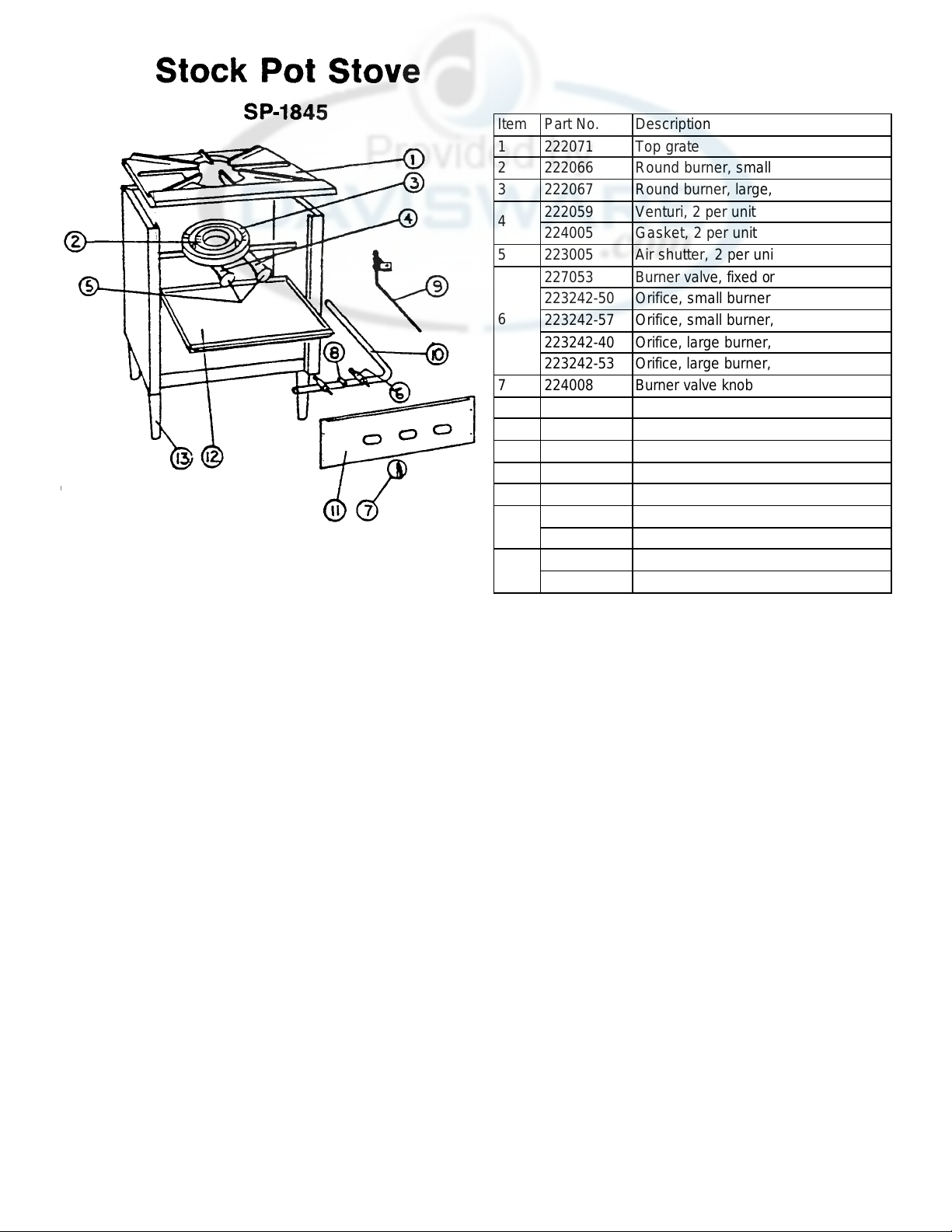
Item Part No. Description
1 222071 Top grate
2 222066 Round burner, small, head only
3 222067 Round burner, large, head only
222059 Venturi, 2 per unit
4
224005 Gasket, 2 per unit
5 223005 Air shutter, 2 per unit
227053 Burner valve, fixed orifice
223242-50 Orifice, small burner, nat gas
6
223242-57 Orifice, small burner, propane
223242-40 Orifice, large burner, nat gas
223242-53 Orifice, large burner, propane
7 224008 Burner valve knob
8 227199 Pilot valve
9 253193 Pilot tubing ass'y, complete
10 223037 Manifold pipe
11 253185 Valve cover
12 253184 Drip pan
223231 Adj legs (each), after 7/15/82
13
223006 Adj legs (each), before 7/15/82
228052-1 Pressure regulator, nat gas
**
228052-2 Pressure regulator, propane
 Loading...