

Page 1
USR-N668 User Manual Technical Support: h.usriot.com
USR-N668 User Manual
File Version: V1.0.4
Jinan USR IOT Technology Limited 1
Page 2

USR-N668 User Manual Technical Support: h.usriot.com
Contents
USR-N668 User Manual ........................................................................................................................................... 1
Features ...................................................................................................................................................................... 4
1. Get Start ............................................................................................................................................................. 5
1.1.Hardware Test ............................................................................................................................................... 5
1.2.NTE Network Test Environment .................................................................................................................... 7
1.3. Default parameter test ................................................................................................................................ 7
2. Product overview ................................................................................................................................................ 9
2.1. Basic parameters ....................................................................................................................................... 10
3. Hardware Design .............................................................................................................................................. 11
3.1. Hardware Dimensions ........................................................................................................................ 11
3.2. Pin definition ..................................................................................................................................... 11
3.2.2. Pin definition .................................................................................................................................. 14
3.2.3. LED Indicator ................................................................................................................................... 14
4. Product Functions ............................................................................................................................................. 15
4.1. Basic Functions .......................................................................................................................................... 15
4.1.1. IP address / Subnet mask / Gateway ............................................................................................... 15
4.1.2. DNS ................................................................................................................................................. 17
4.1.3. VPN-PPTP ........................................................................................................................................ 17
4.1.4. VPN-GRE ......................................................................................................................................... 18
4.1.5. Network diagnosis .......................................................................................................................... 19
4.1.6. Restore factory settings .................................................................................................................. 20
4.1.7. Web Server ..................................................................................................................................... 20
4.1.8. Firmware upgrade........................................................................................................................... 21
4.2. Transtransmission function ........................................................................................................................ 22
4.2.1. TCP Client ........................................................................................................................................ 22
4.2.2. TCP Server ....................................................................................................................................... 24
4.2.3. UDP Client ....................................................................................................................................... 26
4.2.4. UDP Server ...................................................................................................................................... 28
4.2.5. Httpd Client..................................................................................................................................... 29
4.2.6. SSL Client ........................................................................................................................................ 31
4.2.7. V-COM ............................................................................................................................................ 32
4.3. Serial port Functions .................................................................................................................................. 33
4.3.1. Serial port framing mechanism ....................................................................................................... 33
4.3.2. RFC2217-like ................................................................................................................................... 33
4.4. Characteristic function ............................................................................................................................... 34
4.4.1. Socket B .......................................................................................................................................... 34
4.4.2. Heartbeat Packet Function ............................................................................................................. 35
4.4.3. Registration package ....................................................................................................................... 36
4.4.4. Modbus TCP .................................................................................................................................... 37
4.4.5. No data reconnection ..................................................................................................................... 38
4.4.6. DDNS ............................................................................................................................................... 39
4.4.7. Remote management and remote monitoring ............................................................................... 39
Jinan USR IOT Technology Limited 2
Page 3

USR-N668 User Manual Technical Support: h.usriot.com
4.4.8. Scheduled task ................................................................................................................................ 40
5.Parameter setting .................................................................................................................................................. 41
5.1. Network protocol settings parameters ...................................................................................................... 41
5.1.1. Software setting parameters ........................................................................................................... 41
5.1.2. Setting protocol settings parameters .............................................................................................. 43
5.2. Web settings parameters ........................................................................................................................... 43
5.3. AT command .............................................................................................................................................. 46
5.3.1. AT command ................................................................................................................................... 46
5.3.2. Error code ....................................................................................................................................... 47
6.Contact Us ............................................................................................................................................................. 48
7.Disclaimer .............................................................................................................................................................. 48
8.Update History ....................................................................................................................................................... 48
Jinan USR IOT Technology Limited 3
Page 4

USR-N668 User Manual Technical Support: h.usriot.com
Features
Two 10/100Mbps Ethernet port, support Auto-MDI/MDIX.
8 serial ports all support RS232/RS485/RS422.
Support Static IP or DHCP.
TCP Server, TCP Client, UDP Client, UDP Server, HTTPD Client .
8 serial ports all support two sockets ,and all can send data to two different servers when work as Client.
It works as TCP client, supports to 16(max) TCP Client.
Keep-alive & Registration-package.
Modbus TCP to Modbus RTU.
User-defined overtime Reload (no data reload)and overtime connection.
The modifiable , one and only MAC.
DNS domain name resolution ,user-defined DNS server address.
Remote monitoring and remote firmware upgrading.
Network time synchronization +RTC real time clock.
User-defined Task Scheduler.
Supports web server configuration.
Supports V-COM.
Reload by hardware and software.
Run across gateways, switches and routers.
Work in LAN or external network.
Jinan USR IOT Technology Limited 4
Page 5
USR-N668 User Manual Technical Support: h.usriot.com
Jinan USR IOT Technology Limited www.usriot.com
5
1. Get Start
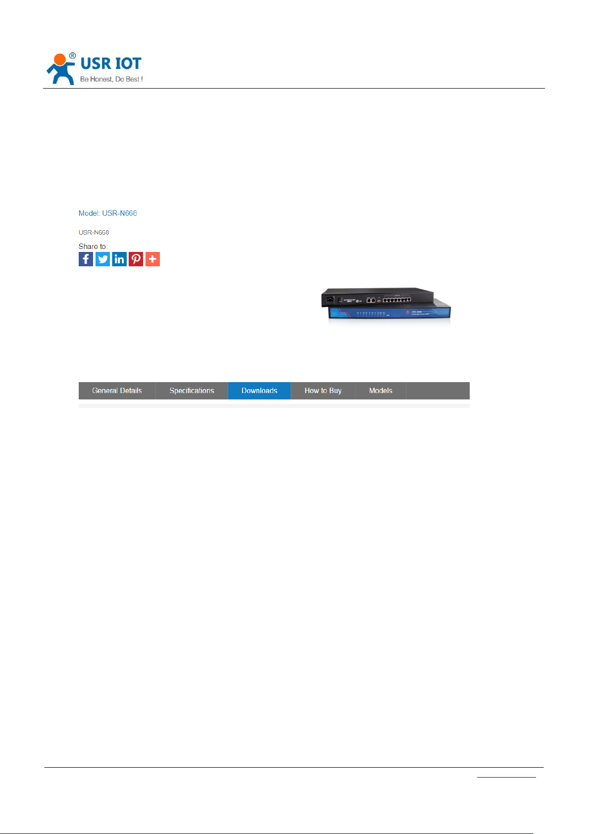
Product link:
http://usriot.com/products/8-ports-serial-to-ethernet-converter.html
Figure 1 Download Page
If you have any question, please submit it back to customer center: http://h.usriot.com
1.1.Hardware Test
1.1.1. Hardware Preparation
You need:
1. USR-N668 for one;
2. Power cord (85V~265V)for one;
3. Female to female serial cable for one;
4. DB9-M to RJ45 for one;
5. Network line for two;
6. PC(with RS232,or USB to 232)
1.1.2. Hardware Connection
For test the communication conversion between serial port and network , you should connect the
USR-N668 to PC with serial cable(or USB to serial cable),connect the Ethernet port of USR-N668 and PC
with network. Make sure the connection is correct , then power on.
ALL the connecting lines form USR IOT;
Page 6
USR-N668 User Manual Technical Support: h.usriot.com
Jinan USR IOT Technology Limited www.usriot.com
6
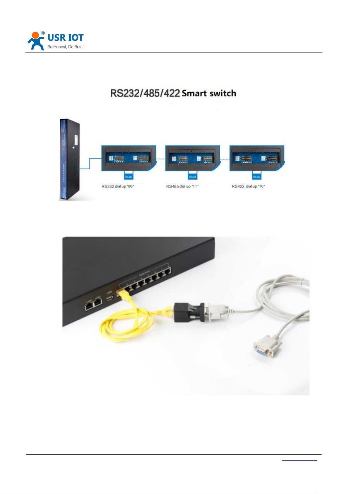
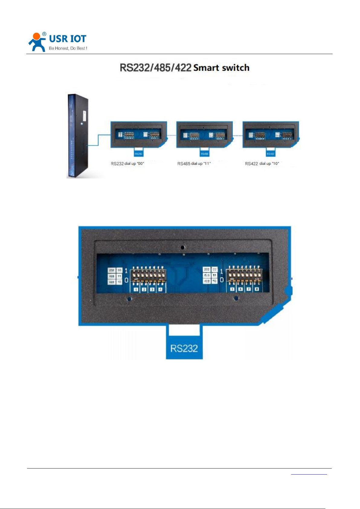
The test only for RS232, factory default setting for RS232;
Check the dial up settings window ,make sure USR-N668 work at correct pattern.(See the details in
Hardware introduce->Dial up)
Figure 1. RS232/485/422 smart switch
N668 serial port 1->network->DB9-M to RJ45->mother to mother serial cable->PC serial port
Figure 2. serial port connection between N668 and PC
The above is the hardware connection diagram of RS232 for transparent transmission. when use
RS485/RS422,you can connect the corresponding signal line.(see the details in Hardware introduce->
Serial port pin definition )
Note: the standard configuration of DB9-M to RJ 45 is only one, if you need more, you need separate
Page 7
USR-N668 User Manual Technical Support: h.usriot.com
Jinan USR IOT Technology Limited www.usriot.com
7
purchase
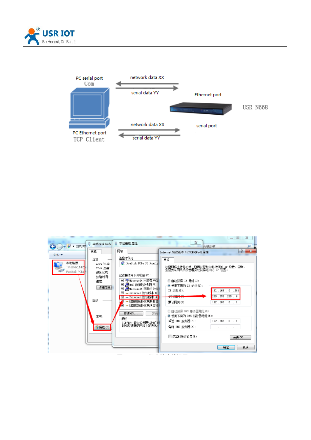
The overall hardware connection and data flow are as follows,
Figure 3. data flow
1.2.NTE Network Test Environment
Before the network test, you should:
1) Close the firewall of the computer (usually found in the control panel)and anti-virus software;
2) Close the network card which is not related to this test, only one local connection is reserved;
3) For servers to connect directly to PC, a static IP (address in the same network segment with USR-N668) must be
set to the PC (e.g.192.168.0.201).
Figure 4. PC local connection settings
1.3. Default parameter test
Table 1 default parameters
Page 8
USR-N668 User Manual Technical Support: h.usriot.com
Jinan USR IOT Technology Limited www.usriot.com
8
Item
Content
User name
admin
Password
admin
IP address
192.168.0.7
Subnet mask
255.255.255.0
Default gateway
192.168.0.1
Default mode of operation
TCP Server
Default target port
20001~20008
Default local port
20001~20008
Default target IP
192.168.0.201
Serial baud rate
115200
Serial port parameters
None/8/1
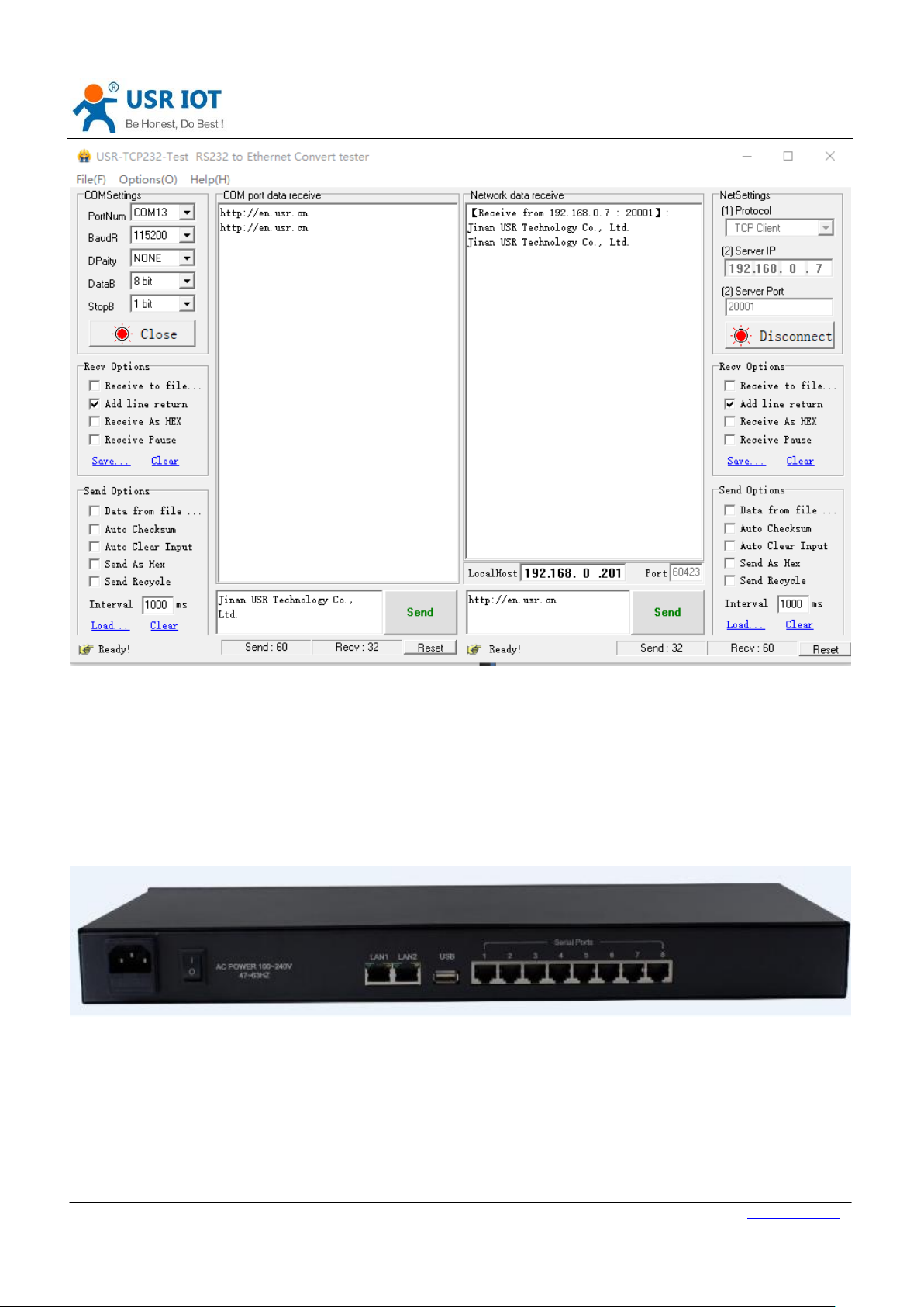
After confirmation, You can carry out the bidirectional between the serial port and the Ethernet port.
Communication procedures are as follows:
1) Open the testing software”USR-TCP232-Test.exe”,connected hardware;
2) The default mode of operation is TCP Server, first port serial port monitor 20001 port. So choose TCP client mode at
the network setup end of the software,IP:192.168.0.7,target port 20001,then click the connect. The serial baud
rate is 115200, The serial port parameter is set to None/8/1,chick open.
3) Send data for test, the data flow form serial port to Net is: PC serial port->668 serial port->668 Ethernet port->PC
network; the data flow form Net to serial port is: PC network->668 Ethernet port->668 serial port->PC serial port.
The specific demo is shown below.
Page 9
USR-N668 User Manual Technical Support: h.usriot.com
Jinan USR IOT Technology Limited www.usriot.com
9
Figure 5. data transmission test
The USR-TCP232-Test.exe download links:
https://www.usriot.com/support/downloads/usr-tcp-test-testing-software.html
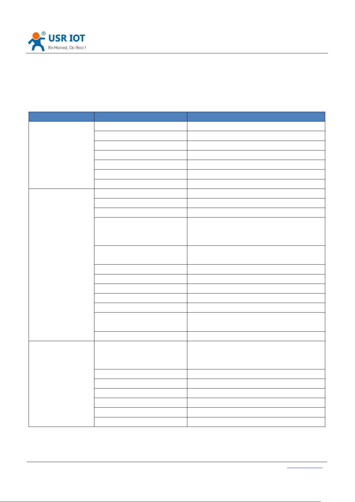
2. Product overview
Figure 6. USR-N668 hardware interface
Page 10
USR-N668 User Manual Technical Support: h.usriot.com
Jinan USR IOT Technology Limited www.usriot.com
10
classification
parameter
numerical
Hardware parameters
Working voltage
AC 85~265V, 50/60Hz
Power Consumption
1.6W
Ethernet Port
RJ45、10/100Mbps
Number of Ethernet port
2
Serial port format
RJ45
Number of serial port
8*RS232/RS485/RS422
Serial baud rate
300-115.2K(bps)
Software parameters
Network protocol
IP、TCP/UDP、ARP、ICMP、IPV4、HTTP、SSL
IP
Static IP、DHCP
Domain name resolution
Support, customize DNS server address
User configuration
Software configuration,
Web page configuration,
AT instruction configuration
Simple pass through mode
TCP Server/TCP Client/SSL Client
UDP Server/UDP Client/Http Client
Class RFC2217
Support
Network cache
10kbyte
Serial port cache
10kbyte
Average transmission delay
>=50ms
Software kit
V-COM,setup software,test program
Packaging mechanism
50ms packing time,
1472 bytes packing length
Certificate
CE/RoHs
Other
Reliability grade
EN61000-4-2(static electricity) Grade 4
EN61000-4-4(pulse group) Grade 4
EN61000-4-5(surge) Grade 3
Shell protection
IP30
Full-size
482*185*45 MM
Work temperature
40~85℃
Storage temperature
40~85℃
Work humidity
5%~95%(Non condensation)
Storage humidity
5%~95%(Non condensation)
2.1. Basic parameters
2.2.
Table 2 Electrical parameters
Page 11
USR-N668 User Manual Technical Support: h.usriot.com
Jinan USR IOT Technology Limited www.usriot.com
11
3. Hardware Design
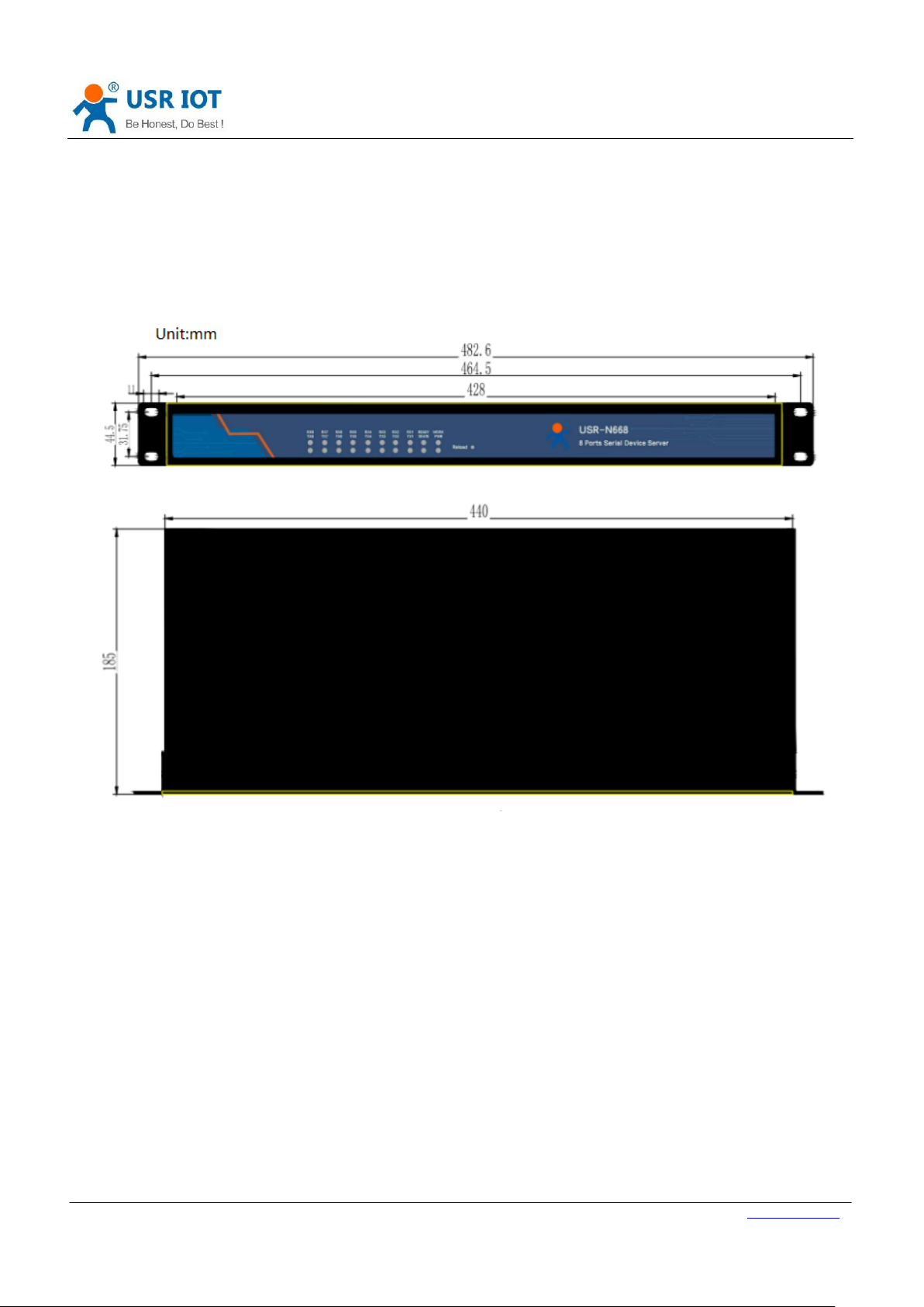
3.1. Hardware Dimensions
Figure 7 Hardware dimensions
3.2. Pin definition
3.2.1. Dial switch
On the back of the equipment, there is a dial up switch setting window.
You need to use the cross flower screwdriver, remove the screws to see.
The following is the setting of the code switch.
Page 12
USR-N668 User Manual Technical Support: h.usriot.com
Jinan USR IOT Technology Limited www.usriot.com
12
Figure 8. RS232/485/422 smart switch
A total of 16 (8 serial port * 2) dial code. The device has 8 serial ports and 2 dial numbers per route, as shown in the
figure.
Figure 9. RS232 model
Page 13
USR-N668 User Manual Technical Support: h.usriot.com
Jinan USR IOT Technology Limited www.usriot.com
13
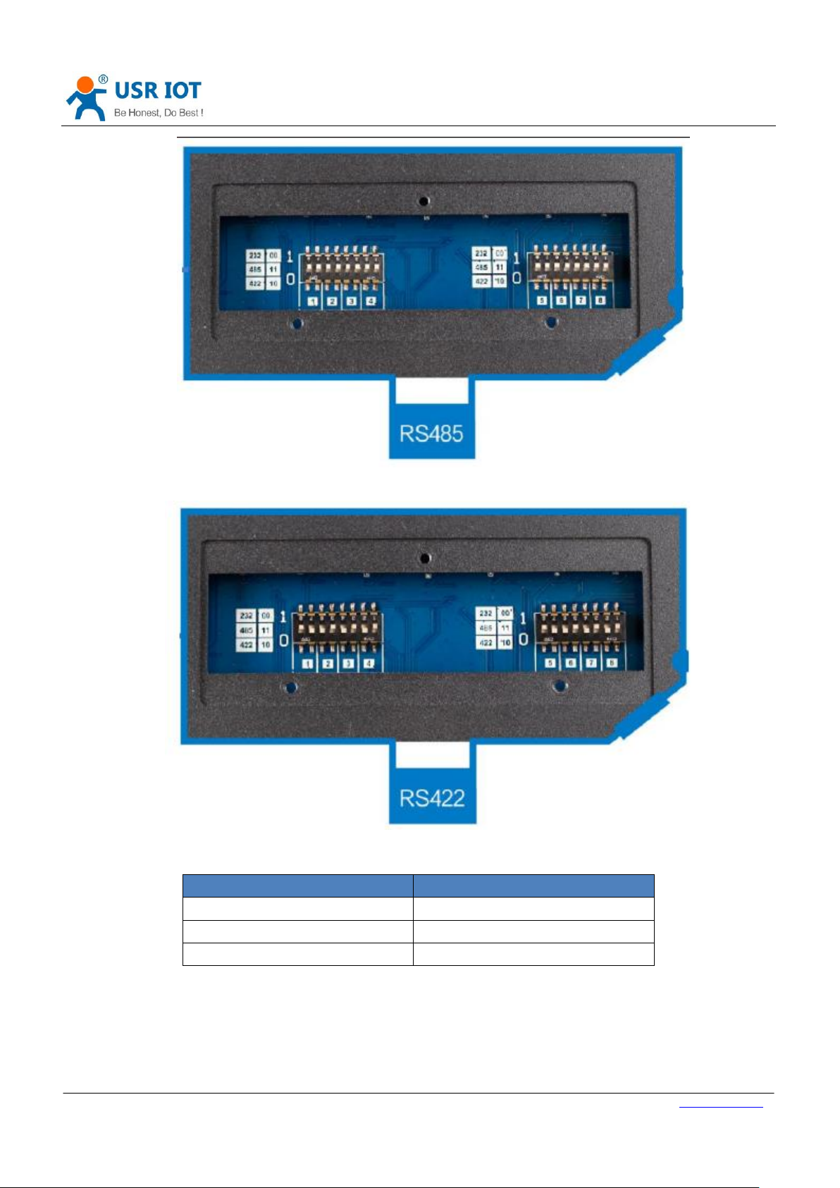
communication mode
Dial switch(L to R)
232
0 0
485
1 1
422
1 0
Figure 10. RS485 model
Figure 11. RS422 model
Table 3 Correspondence
Pay attention:
The switch position is shown in the figure.
The dialing sequence form L to R.
Default is 232 mode,the dial switch is “0 0”.
Page 14
USR-N668 User Manual Technical Support: h.usriot.com
Jinan USR IOT Technology Limited www.usriot.com
14
Pin Number
Name
Function
1
232_TX/422_Z/485_B1
232 send;422 signal Z;485 signal B
2
232_RX/422_A1
232 receive;422 signal A
3
422_Y/485_A1
422 signal Y;485 signal A
4
422_B1
422 signal B
5
NC 6
GND
232 signal GND
7
NC 8
NC
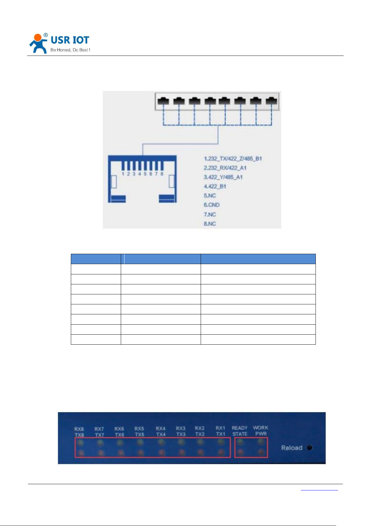
3.2.2. Pin definition
The serial port pin diagram is as follows (The hardware interface is RJ45).
Figure 12. Serial line sequence
Table 4 Serial line sequence
Pay attention:
232,485,422 can’t work at one time;
The position of the dialing switch must be correct.
The hardware interface is RJ45, you need to use 8 core cable and crystal head to make communication cables.
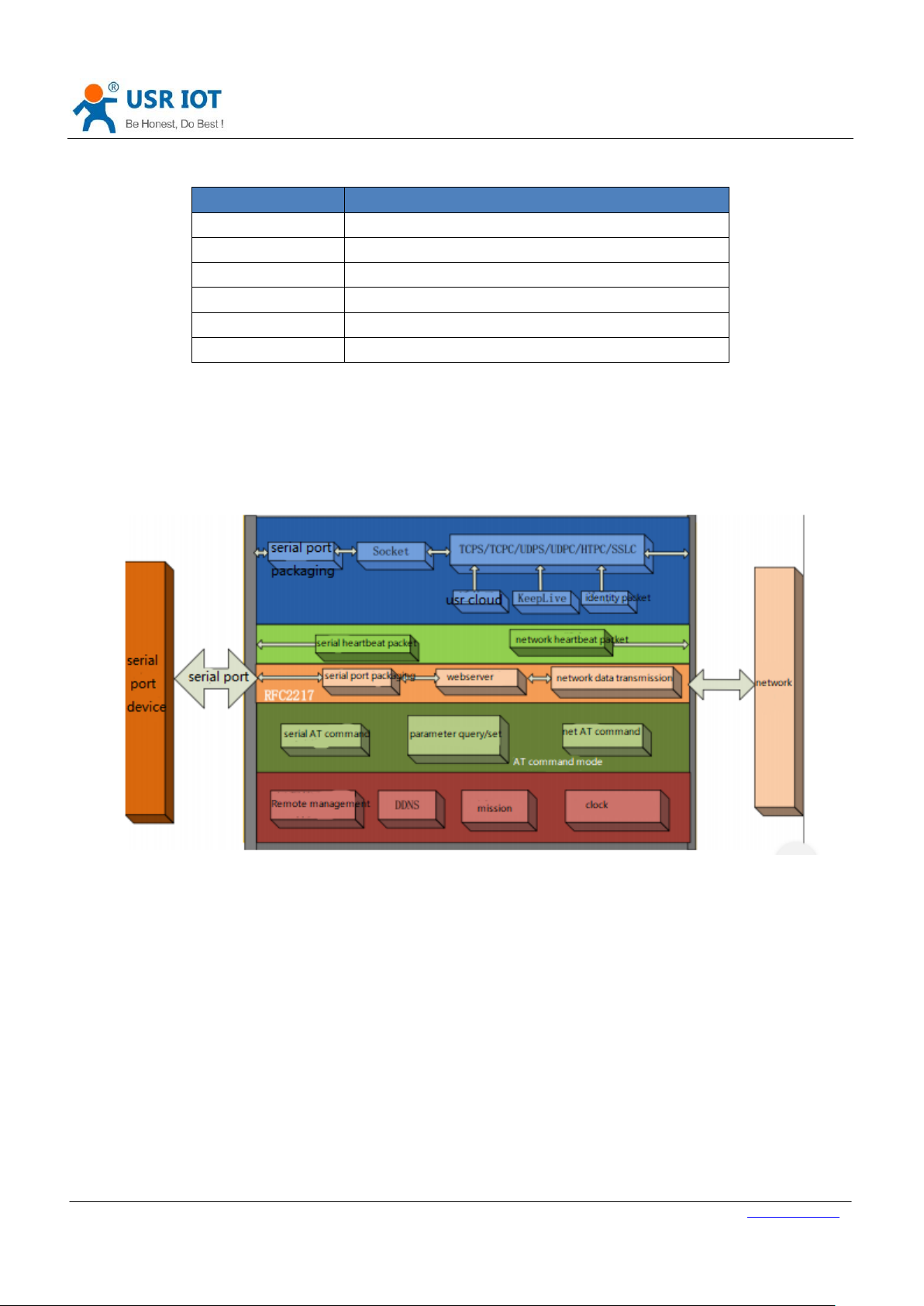
3.2.3. LED Indicator
Figure 13. LED location
Page 15
USR-N668 User Manual Technical Support: h.usriot.com
Jinan USR IOT Technology Limited www.usriot.com
15
Indicator
Function
PWR
Red/On: Power on
WORK
Green/ Flicker: Working
STATE
Red/ Undefined
READY
Green/On: working
TXN
Red/Flicker: Serial port sending data
RXN
Green/Flicker: Serial port receiving data
LED status reference table.
Table 5 LED indicator
4. Product Functions
This chapter introduces the functions of USR-N668 as the following diagram shown, you can get an overall knowledge
of it.
Figure 14 Product 668 Functions diagram
4.1. Basic Functions
4.1.1. IP address / Subnet mask / Gateway
There are two ways for module to get IP address: Static IP and DHCP.
Page 16

USR-N668 User Manual Technical Support: h.usriot.com
Jinan USR IOT Technology Limited www.usriot.com
16
IP acquisition mode
Advantage
Static IP
Default setting of module is Static IP and default IP is
192.168.0.7. When user set module in Static IP mode, user need
set IP, subnet mask and gateway and must pay attention to the
relation among IP, subnet mask and gateway.
DHCP
Module in DHCP mode can dynamically get IP, Gateway, and DNS
server address from Gateway Host. When user connect directly
to PC, module can’t be set in DHCP mode. Because common
computer does not have the ability to assign IP addresses.
AT command
Describe
Figure 15 IP address setup
Table 6 Station IP and DHCP
Subnet mask is mainly used to determine the IP address of the network number and host number, indicating the
number of subnets, judging whether the module is in the subnet flag. Subnet Masks must be set , we usually use the C
class subnet mask: 255.255.255.0, network number for the first 24 bits, host number for the last 8 bits, the number of
subnets For the 255 module IP in 255 scopes, the module IP is considered in this subnet.
Gateway refers to the network number of the module where the current IP address is located. If you connect to devices
such as routers when connecting to the outside network, the gateway is the router IP address, if set up incorrectly, you
can’t access the outside network correctly, if you do not connect to devices such as routers, you do not need to set up,
the default can be.
Reference AT command
Table 7 Station IP /DHCP AT command
Page 17

USR-N668 User Manual Technical Support: h.usriot.com
Jinan USR IOT Technology Limited www.usriot.com
17
AT+WANN
Set and query IP, IP/ subnet mask / gateway parameters
AT command
Describe
AT+DNS
Set and query DNS server
4.1.2. DNS
DNS server address , default master server 208.67.222.222, standby server 8.8.8.8.
DNS server address can be set, can achieve domain name resolution in the case of imperfect local domain name server,
users can also set the address of a specific DNS server according to needs, 668 need domain name resolution will be set
to the DNS server to submit a resolution request.
In the case of DHCP, the domain name server address is automatically acquired.
Figure 16 DNS server
Reference AT command
Table 8 DNS AT command
4.1.3. VPN-PPTP
Support the VPN link of PPTP protocol.
Figure 17 PPTP set
Remote address, user name, password are the basic parameters; there are encryption, authentication and other
parameters can be set.
Page 18

USR-N668 User Manual Technical Support: h.usriot.com
Jinan USR IOT Technology Limited www.usriot.com
18
Figure 18 Data encryption
Data encryption: support MPPE, MPPE-128 and other encryption methods.
Authentication: support PAP, CHAP, MSCHAP, MSCHAPv2, etc.
LCP response interval: the default heartbeat interaction interval is 300 seconds.
MTU: maximum transmission unit, default 1500, can be reduced according to requirements.
4.1.4. VPN-GRE
Support VPN-GRE
Page 19

USR-N668 User Manual Technical Support: h.usriot.com
Jinan USR IOT Technology Limited www.usriot.com
19
Figure 19VPN-GRE
There are four main parameters. remote address, local address, remote tunnel address, and local tunnel address. After
the GRE is established, the two sides can interoperate and visit each other on IP.
4.1.5. Network diagnosis
The network diagnostic function supports Ping instructions for testing the network link.
e.g.: ping www.baidu.com -w 3
-w indicates the duration of Ping.
Page 20

USR-N668 User Manual Technical Support: h.usriot.com
Jinan USR IOT Technology Limited www.usriot.com
20
Figure 20 network diagnostic function
4.1.6. Restore factory settings
1) Hardware buttons: Press the Reload button between 5S and 15s to restore the factory settings , and no restore will
be performed if less than 5S or more than 15s. When the module parameter is configured erroneous or if you forget to
set the password, you can use the hardware to restore the factory settings.
2) Setting up software: setting up the factory's function by setting up the software.
3) AT instruction: enter AT instruction mode and resume factory by instruction AT+RELD.
4) Web page: restore the factory button.
4.1.7. Web Server
Built-in web server, users can set parameters through the web page and also can view the relevant state of the module.
The default home page is the current status interface, which is refreshed every 5s, showing the working status of 668.
Page 21

USR-N668 User Manual Technical Support: h.usriot.com
Jinan USR IOT Technology Limited www.usriot.com
21
Figure 21 668 working status
4.1.8. Firmware upgrade
The specific upgrading methods are as follows.
Figure 22 668 firmware upgrade 1
Choose the firmware path.
Page 22

USR-N668 User Manual Technical Support: h.usriot.com
Jinan USR IOT Technology Limited www.usriot.com
22
AT command
Describe
AT+SOCK
Set up Socket work mode / target IP/ target port
Figure 23 668 firmware upgrade 2
File transfer is finished, click confirm for firmware upgrade.
Figure 24 668 firmware upgrade 3
After waiting for 100 seconds, the firmware brush is finished, and you can login again.
Figure 25 668 firmware upgrade 4
Attention:
No power failure during the process of firmware brush writing.
The process of writing and restarting is expected to be 100 seconds (see page timing), and then the device can be
revisited.
You can choose whether to retain parameters, and don ‘t retain them by default.
The official firmware must be used.
4.2. Transtransmission function
668 Socket work mode: TCP Client, TCP Server, UDP Client, UDP Server, Httpd Client. SSL Client.
Reference AT command
Table 9 TCP Client AT command
4.2.1. TCP Client
Page 23

USR-N668 User Manual Technical Support: h.usriot.com
Jinan USR IOT Technology Limited www.usriot.com
23
Figure 26 TCP Client work mode
1) TCP Client provides client connection for TCP network services. Initiatively connection requests to the server and
establishes connections to achieve serial numbers interaction with server data. According to the relevant provisions of
the TCP protocol, TCP Client is the difference between connection and disconnection, so as to ensure data reliable
exchange. Usually used for data interaction between devices and servers, is the most commonly used network
communication mode.
2) The pattern has the function of actively identifying connection anomalies. When the connection is established,
several “Keep Alive” are sent after 60 seconds of no data for the first time .If the connection is abnormal interruption, it
will be immediately detected, and prompted 668 to disconnect the original connection and reconnect (The formula is
60 + 5*3 = 75 s).
3) This model supports synchronous baud rate function, USR-cloud function and short connection function.
4) In the same LAN, if 668 is set to static IP, keep 668 IP and gateway in the same network segment, and set gateway IP
correctly, otherwise it will not be able to communicate properly.
5) When 668 work as TCP Client, you need to pay attention to target IP / domain name and target port number. If you
connect a server across a public network, the server must has public network IP or domain name.
6) When 668 work as TCP Client, the local port NO. suggest to set to 0, so that 668 can access the server with random
port number.
7) TCP Client communication examples
① work mode :TCP Client, IP: 192.168.0.201, teleport: 20001 .Then save parameters and restart.
Page 24

USR-N668 User Manual Technical Support: h.usriot.com
Jinan USR IOT Technology Limited www.usriot.com
24
Figure 27 TCP Client web page setting
②”USR-TCP232-Test.exe”work as TCP Server, the local IP address is the IP address of PC,e.g.192.168.0.201, listening
port:20001,then click listening. Software shows Connection objects: 192.168.0.7:20001. Open the serial port.
③Click send, you can transmission data now.
Figure 28 TCP Client transmission test
4.2.2. TCP Server
Figure 29 TCP Server
1) when 668 work as TCP Server, there are "Keep Alive" functions ,for real-time monitoring.
2) Use for TCP client communication to LAN. It is suitable for the scenario where there is no server in the LAN and
multiple computers or mobile phones request data from the server. Like TCP Client, there are differences between
connection and disconnection to ensure reliable exchange of data.
3) When work as TCP Server, it support Synchronous baud rate(RFC2217).
4) Active monitoring of local ports when 668 work as TCP Server, When connecting requests, respond and create
Page 25

USR-N668 User Manual Technical Support: h.usriot.com
Jinan USR IOT Technology Limited www.usriot.com
25
connections. If you cross the public network to access 668 of TCP Server, you need port mapping on the router.
5) In the case of TCP Server, 668 can accept up to 16 Client connections, and the local port number can't be set to 0.
6) 668 work as TCP Server. When the number of connections Client exceeds the maximum set, it will no longer be
accessible.
7) ①668 work as TCP Server, local port:20001(The default is from 20001~20008. make sure that the local ports of
each path are different),then save.
②There are two ways to set up, use web pages or software.
③Click send, you can transmission data.
Figure 30 TCP Server setting
Page 26

USR-N668 User Manual Technical Support: h.usriot.com
Jinan USR IOT Technology Limited www.usriot.com
26
Figure 31 TCP Server transmission test
4.2.3. UDP Client
Figure 32 UDP Client mode
1) UDP transport protocol provides simple and unreliable communication services. No connection connected
/disconnected.
2) When work at UDP Client, 668 only communication with target IP.
3) Target IP:255.255.255.255, it can achieve the effect of UDP full segment broadcast. 4015 and later firmware
supports broadcast in the network segment, such as xxx.xxx.xxx.255's broadcast mode.
4) Can't support multicast.
5) ①Set up UDP Client ,target port:8234.
Page 27

USR-N668 User Manual Technical Support: h.usriot.com
Jinan USR IOT Technology Limited www.usriot.com
27
Figure 33 UDP Client web set
②The software is set to UDP, the local IP is set to the PC IP, and the local port number is the target port number
of 668. Click Connect. Open the serial port.
③First click the serial port to send, receive the data, test software target IP and target port number to 668 IP and
port number, and then click the network to send data to the serial port.
Page 28

USR-N668 User Manual Technical Support: h.usriot.com
Jinan USR IOT Technology Limited www.usriot.com
28
Figure 34 UDP Client test
4.2.4. UDP Server
Figure 35 UDP Server mode
1) UDP Server means that the source IP address is not verified on the basis of ordinary UDP. After receiving a UDP
packet, the destination IP is changed to the data source IP and port number. When sending data, the IP and port
number are sent to the nearest communication.
2) This mode is usually used in data transmission scenarios where multiple network devices need to communicate
with modules and do not want to use TCP because of their high speed and frequency.
3) ①Set up UDP Server, target port 20108.
②Open the “USR-TCP232-Test.exe”,set up UDP mode, the local IP is the PC IP. Set the port diffident, e.g.23 and
8234, click “connect”. On the other side , set the IP and port all the 668 parameter.
Page 29

USR-N668 User Manual Technical Support: h.usriot.com
Jinan USR IOT Technology Limited www.usriot.com
29
③Click the network send button on the software, the serial port receives all the data; click the send button on the
serial port, and the software receives data only from the latest one communication with 668.
④The setup method is the same as UDP Client.
Figure 36 UDP Server testing
4.2.5. Httpd Client
1) In this mode, the user's terminal device can send the request data to the specified HTTP server through 668, and
then 668 receives the data from the HTTP server, parses the data and sends the result to the serial port device.
2) Simple parameter settings, can transmission data from serial device to HTTP server.
3) Each time the data is sent, only the request data is sent, and 668 automatically adds information such as URL and
packet header.
4)
Page 30

USR-N668 User Manual Technical Support: h.usriot.com
Jinan USR IOT Technology Limited www.usriot.com
30
Figure 37 Httpd Client web set
1. set up Httpd Client, target IP, domain name and target port.
2. Set up Httpd request mode through web page, and request URL and packet header information of
package.
3. Httpd server recovery information packet header default removed.
4. Save and reload.
5. Now can send data after open serial port.
6. Reference below.
Page 31

USR-N668 User Manual Technical Support: h.usriot.com
Jinan USR IOT Technology Limited www.usriot.com
31
Figure 38 Httpd Client mode
4.2.6. SSL Client ( Does not support in the current firmware)
Support SSL encryption on TCP links.
Target address: www.alipay.com , target port 443.
Page 32

USR-N668 User Manual Technical Support: h.usriot.com
Jinan USR IOT Technology Limited www.usriot.com
32
Figure 39 SSL Client setting
The HTTP request command has a carriage return line between adjacent rows.
GET https://www.alipay.com/
User-Agent: Mozilla/4.0
Host: www.alipay.com
Figure 40 SSL Client test
4.2.7. V-COM
Figure 41 V-COM
User can download VCOM software from http://www.usriot.com/usr-vcom-virtual-serial-software/. Through this
software user can set up connection between N668 and virtual serial to solve the problem that traditional equipment
PC software used in serial port communication way.
1. set 668 TCP Server.
2. ①open V-COM, and add serial port;
②try to connect with 668.
3. e.g. as follow:
Page 33

USR-N668 User Manual Technical Support: h.usriot.com
Jinan USR IOT Technology Limited www.usriot.com
33
Figure 42 V-COM setting
4.3. Serial port Functions
4.3.1. Serial port framing mechanism
Because the data on the network side are transmitted in data frames, it is necessary to send the frame data through the
serial port to the network side, so that the data can be transmitted more efficiently and quickly.
4.3.2. RFC2217-like
Page 34

USR-N668 User Manual Technical Support: h.usriot.com
Jinan USR IOT Technology Limited www.usriot.com
34
Figure 43 RFC2217
The RFC2217-like function realizes the function of dynamically changing the parameters of USR-N668 serial port from
the network side during the operation of USR-N668. For example, in the running process, the serial port baud rate of
the 668 server is changed from 115200bps to 9600bps.
RFC2217-like functions are mainly used in conjunction with VCOM. The default is the open state.
4.4. Characteristic function
4.4.1. Socket B
Implement a simple TCP / UDP Client function, the data received by the serial port, and send to Socket A and Socket B,
and vice versa. It can be used for data backup links, and the working mechanism is consistent with Socket A.
Page 35

USR-N668 User Manual Technical Support: h.usriot.com
Jinan USR IOT Technology Limited www.usriot.com
35
Figure 44 TCP Server setting
4.4.2. Heartbeat Packet Function
Heartbeat packet: Module will output heartbeat data to serial or network periodic. User can configure the heartbeat
data and time interval. Serial heartbeat data can be used for polling Modbus data. Network heartbeat data can be used
for showing connection status and keep the connection (only take effect in TCP/UDP Client mode).
The longest for Custom heartbeat package content is 40 bytes, the heartbeat time is 30 seconds, the range is 1~65535
seconds.
Page 36

USR-N668 User Manual Technical Support: h.usriot.com
Jinan USR IOT Technology Limited www.usriot.com
36
Heartbeat packet can set through the web.
Figure 45 heartbeat packet function
Figure 46 heartbeat packet function
4.4.3. Registration package
There are three kinds of registration packages: Custom registration package, transparent cloud, MAC registration
package. Here is a custom registration package.
Page 37

USR-N668 User Manual Technical Support: h.usriot.com
Jinan USR IOT Technology Limited www.usriot.com
37
Custom registry packages have three kinds of situations: connection sending registry packages, data carrying registry
packages, full registration (both are executed). Content can be based on customers. The user needs to be changed
arbitrarily, up to 40 bytes, and supports sixteen binary input.
Set up a connection to send a registry packet: After the connection is established, send the registry packet
immediately, the main purpose is to enable the server to identify the data source device, or as a password to
obtain server function authorization.
Figure 47 send registration package after connection
Data portability: put the registration packet in the front of data, which is mainly used for protocol transmission.
Figure 48 data with registration package
The function can be set through web pages.
4.4.4. Modbus TCP
Figure 49 registration package
This device provides ModbusTCP turn to ModbusRTU function and defaults by default.
Page 38

USR-N668 User Manual Technical Support: h.usriot.com
Jinan USR IOT Technology Limited www.usriot.com
38
Figure 50 modbus TCP data flow
Figure 51 modbus TCP setting
Figure 52 modbus TCP test
4.4.5. No data reconnection
Page 39

USR-N668 User Manual Technical Support: h.usriot.com
Jinan USR IOT Technology Limited www.usriot.com
39
The device provides a way to disconnect and reconnect, to eliminate the existence of dead links, the default function is
86400 seconds, that is, 24 hours.
When a TCP link is established and no data is received for a certain period of time, the device disconnects and
reconnects the current link (note that only the TCP Client does).This eliminates the existence of some dead links to
facilitate the stability of PC software.
Figure 53 no data reconnection setting
4.4.6. DDNS
Support dynamic DNS.
Figure 54 DDNS setting
Figure 55 DDNS test
4.4.7. Remote management and remote monitoring
Remote monitoring realizes remote device state management.
Through server software, we can see the on-line state, running time and traffic information of the device.
Default not open.
Page 40

USR-N668 User Manual Technical Support: h.usriot.com
Jinan USR IOT Technology Limited www.usriot.com
40
Figure 56 Remote management and remote monitoring
Remote firmware upgrade can upgrade firmware by server.
The default is not opened.
Figure 57 Remote firmware upgrade
Attention:
This function and remote server are all trial run.
Remote server login address https://ycsj1.usr.cn/index.php/Public/login
4.4.8. Scheduled task
This function can carry out instructions to the device by way of dividing, time, day, month and week.
Syntax is shell instruction.
Page 41

USR-N668 User Manual Technical Support: h.usriot.com
Jinan USR IOT Technology Limited www.usriot.com
41
Figure 58 scheduled task
5.Parameter setting
668 setting parameter method : software and web page.
User configuration process:
Search-Setting IP Address Acquisition- Serial Port Parameters-668 Working Mode-Work parameters
In order to ensure the normal use of the software, we need to take the following steps:
1. When setting parameters with settings software, it is necessary to ensure that all device in the same LAN.
2. turn off the anti-virus software and firewall on the computer.
3. close the NIC that has nothing to do with this test.
5.1. Network protocol settings parameters
5.1.1. Software setting parameters
Search all the N668 in the LAN.
Page 42

Jinan USR IOT Technology Limited www.usriot.com
42
1. Read parameter
USR-N668 User Manual Technical Support: h.usriot.com
Figure 59 search
Figure 60 equipment operation
2. Setting the main parameter
Figure 61 Setting the main parameter
IP address type: static and DHCP
The static IP:668 is set up in the same network segment as router IP.
Subnet mask: General default 255.255.255.0
Gateway: generally routers IP, set up correctly in order to cross network segment communication, and domain
name resolution.
Device name: the name can be customized.
Webpage port: port number when accessing web page is default 80
3. Serial port parameter setting
Page 43

USR-N668 User Manual Technical Support: h.usriot.com
Jinan USR IOT Technology Limited www.usriot.com
43
Figure 62 Serial port parameter setting
Serial baud rate: baud rate of serial communication , does not support custom baud rate.
Check / data / stop: serial port parameters
Work mode: 668 of the work is TCP Server /TCP Client/HTTPD Client/UDP Client/ UDP Server
Target IP / Domain Name: The target IP which 668 work as the client (TCP Client / HTTPD Client / UDP Client)
Local port: set 0 when 668 work as TCP Client, i.e. issued as a random port number
Attention:
When using the software to set parameters through the network, the display will be forced to open.
Configure parameters through serial port. As follows, the steps are to operate through the serial port - > open the
serial port - > enter the configuration state, and then click read reference.
Figure 63 software
Modify PC's IP and module in the same network segment, or use serial configuration parameters.
5.1.2. Setting protocol settings parameters
By setting up the protocol, you can complete the process of search > setting > Restart (save parameters).
5.2. Web settings parameters
Open the browser and enter the IP address of 668. By default (192.168.0.7), you can open the login interface of 668.
Enter
user name: admin
Password admin
Click login, you can enter the login screen.
Page 44

USR-N668 User Manual Technical Support: h.usriot.com
Jinan USR IOT Technology Limited www.usriot.com
44
Figure 64 login in
Figure 65 web shows
1. The current status page shows some basic information about 668:
668 name
Current IP address
MAC address
2. Local IP settings
Modify the parameters that need to be set on this page, click Save Settings, and then modify the parameters of the next
page. If no other parameters need to be changed, Click Restart.
IP address acquisition mode
IP
Subnet mask
gateway address
DNS server
Page 45

USR-N668 User Manual Technical Support: h.usriot.com
Jinan USR IOT Technology Limited www.usriot.com
45
3. Port parameters
Baud rate
Data bits
Check digit
Stop bits
The way of work
Remote server address
Local port
Remote port
Special functions
Figure 66 IP setting
Page 46

USR-N668 User Manual Technical Support: h.usriot.com
Jinan USR IOT Technology Limited www.usriot.com
46
Figure 67 port parameters
4. Extension function
Customize heartbeat package function: it can be opened through web page, content is customized, the longest is
40 bytes.
Custom registration package function: can be opened through the web page, content customization, up to 40
bytes, the use of custom registration package.
USR-Cloud number and password.
Synchronization baud rate (2217): the function of synchronous baud rate can be opened through webpage.
5.3. AT command
5.3.1. AT command
The UART port: baud rate 115200, no check, 8 bit data bits, 1 bit stop bits.
Input "+ + +" on UART, the module will return a confirmation code "a" after receiving "+ + +".
Enter the confirmation code "a" on UART. After receiving the confirmation code, the module returns the
confirmation of "+OK" and enters the command mode.
Page 47
USR-N668 User Manual Technical Support: h.usriot.com
Jinan USR IOT Technology Limited www.usriot.com
47
Error code
Describe
-1
Invalid command format
-2
Invalid command
-3
Invalid operator
-4
Invalid parameters
-5
operation not permitted
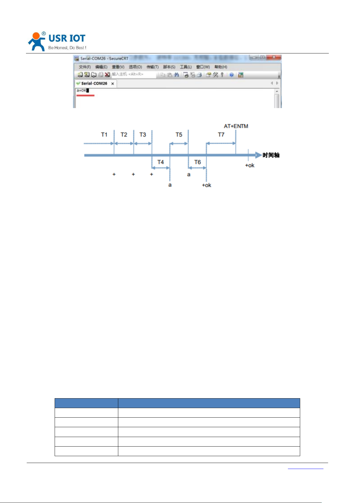
Figure 68 AT command
Figure 69 Time sequence diagram
Time requirements:
T1 > serial port packing interval
T2 < < 300ms
T3 < < 300ms
T5 < < 3S
The transition from transmissions mode to temporary instruction mode:
1. The serial port device sends "++" to the module continuously. When the module receives "++", it sends a "a" to the
device. No data can be sent before sending "+ + +".
2. When the device receives "a", it must send a "a" to the module within 3 seconds.
3. After receiving the "a", module sends the "+OK" to the device and enters the "AT instruction mode".
4. When the device receives "+OK", it knows that the module has entered "AT instruction mode" and can send AT
instructions to it.
Switching from the AT instruction mode to the network pass through sequence:
1. The serial port sends the instruction "AT+ENTM" to the module.
2. Module returns the "+OK" after receiving the instruction and returns to the previous mode.
5.3.2. Error code
Table 10 Error code
Page 48

USR-N668 User Manual Technical Support: h.usriot.com
Jinan USR IOT Technology Limited www.usriot.com
48
Edition
Describe
V1.0.1
2017-07-14 establish
V1.0.2
2017-07-20 modify web page screenshots, statements
V1.0.3
remove hardware manual description
V1.0.4V
add number of accessories
6.Contact Us
Company: Jinan USR IOT Technology Limited
Address: Floor 11, Building 1, No. 1166 Xinluo Street, Gaoxin District, Jinan, Shandong, 250101, China
Web: www.usriot.com
Support: h.usriot.com
Email: sales@usr.cn
Tel: 86-531-88826739/86-531-55507297
7.Disclaimer
This document provide the information of USR-N668 products, it hasn’t been granted any intellectual property license
by forbidding speak or other ways either explicitly or implicitly. Except the duty declared in sales terms and conditions,
we don’t take any other responsibilities. We don’t warrant the products sales and use explicitly or implicitly, including
particular purpose merchantability and marketability, the tort liability of any other patent right, copyright, intellectual
property right. We may modify specification and description at any time without prior notice.
8.Update History
 Loading...