

Page 1
USR-G785-E User Manual Technical Support: h.usriot.com
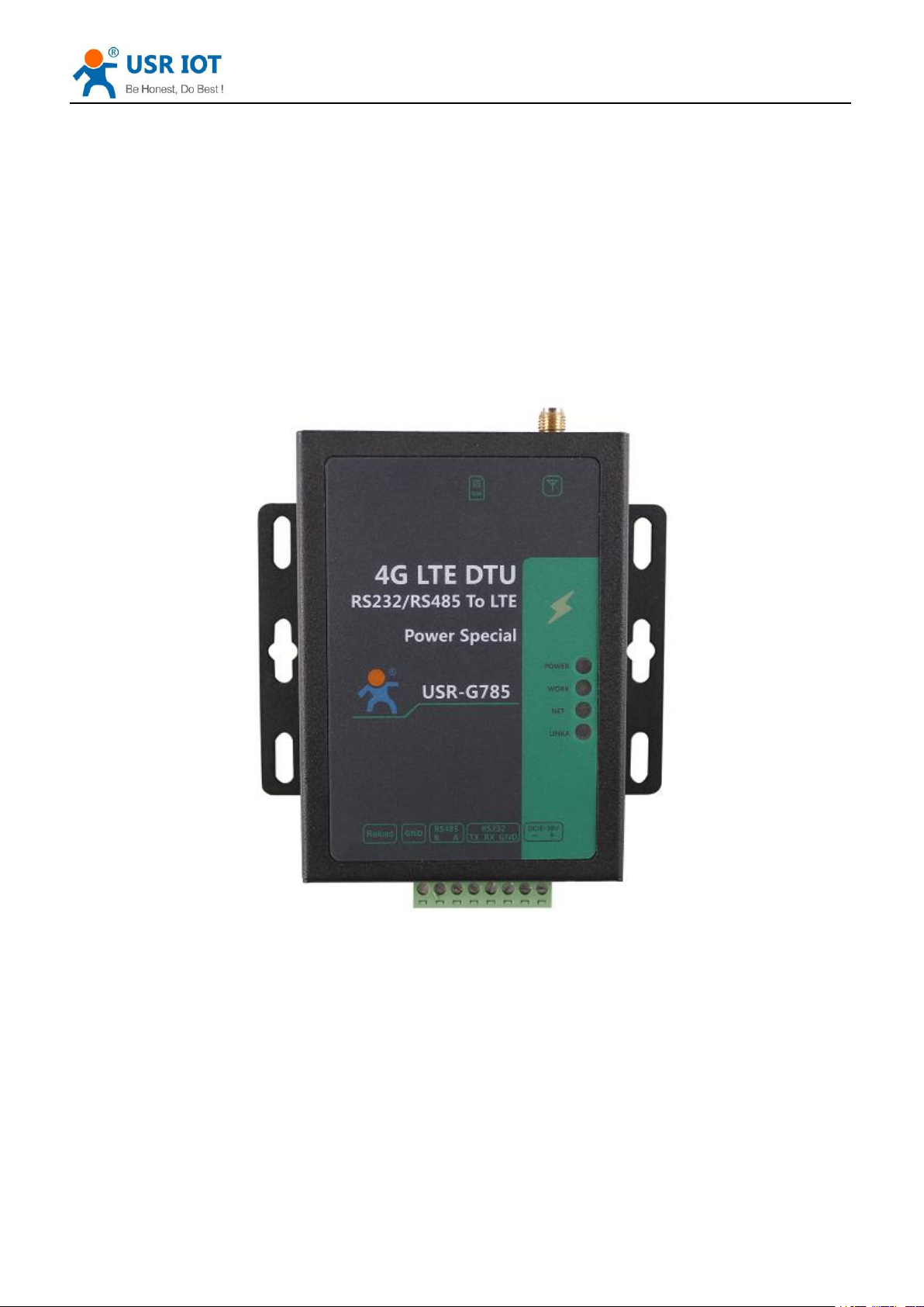
USR-G785-E User Manual
File Version: V1.0.3
Jinan USR IOT Technology Limited
1
Page 2

USR-G785-E User Manual Technical Support: h.usriot.com
Contents
USR-G785-E User Manual......................................................................................................................................1
Features.......................................................................................................................................................................3
1. Get Start...............................................................................................................................................................4
1.1. Hardware Test..................................................................................................................................... 4
1.1.1. Hardware Preparation............................................................................................................... 4
1.2. Data Transmission Test.......................................................................................................................5
1.2.1. Initial Parameters....................................................................................................................... 5
2. Product Overview................................................................................................................................................6
2.1. Product Introduction..........................................................................................................................6
2.2. Module Default Parameters...............................................................................................................6
2.3. Hardware Description........................................................................................................................ 7
2.4. Interface Introduce............................................................................................................................. 9
3. Product Function.................................................................................................................................................9
3.1. Work Mode........................................................................................................................................ 11
3.1.1. Net Transparent Transmission Mode......................................................................................11
3.1.1.1. Mode Declaration......................................................................................................11
3.1.2. UDC Mode................................................................................................................................. 13
3.1.2.1. Mode Description......................................................................................................13
3.2. Serial Port..........................................................................................................................................14
3.2.1. Basic Parameters.......................................................................................................................14
3.2.2. Frame Forming Mechanism.................................................................................................... 15
3.2.2.1. Time Trigger..............................................................................................................15
3.2.2.2. Length Trigger.......................................................................................................... 15
3.2.3. RFC2217 Similar Function...................................................................................................... 15
3.3. Characteristic Function....................................................................................................................16
3.3.1. Registration Package Function................................................................................................16
3.3.2. Heartbeat Packet.......................................................................................................................18
3.3.3. Indicator Status.........................................................................................................................19
3.3.4. Firmware Upgrade....................................................................................................................19
3.3.5. Restore to The Factory Settings.............................................................................................. 19
4. Parameter Setting..............................................................................................................................................20
4.1. AT Commands Setting......................................................................................................................20
4.1.1. Setup Software.......................................................................................................................... 20
4.1.2. Net AT Command..................................................................................................................... 20
4.1.3. SMS AT Command................................................................................................................... 21
5. AT Commands...................................................................................................................................................21
6.Contact Us.............................................................................................................................................................. 23
7.Disclaimer..............................................................................................................................................................23
8.Update History......................................................................................................................................................23
Jinan USR IOT Technology Limited
2
Page 3

Features
Support TCP Client and UDP Client
Support register package and heartbeat package
Support setting parameters by SMS
Support net transparent transmission mode and UDC mode
Support AT commands
Support RFC2217 similar function
Support apply server-side secondary development information
USR-G785-E User Manual Technical Support: h.usriot.com
Jinan USR IOT Technology Limited
3
Page 4
USR-G785-E User Manual Technical Support: h.usriot.com
Jinan USR IOT Technology Limited www.usriot.com
4
1.Get Start
1.1. Hardware Test
1.1.1. Hardware Preparation
1. Connect G785-E and PC with USB-RS232 serial cable;
2. Install antenna;
3. Install SIM card;
4. Power on G785-E with 9-36V DC power supply.
USR-G785-E is a product developed for serial devices and network servers to transmit data to each other. With
simple AT instructions, it is easy to use this product to realize two-way data transparent transmission from serial
port to network.
This chapter is a quick introduction to the USR-G785-E product. New users are advised to read this chapter
carefully and follow instructions to get a systematic understanding of the product. Users can skip this chapter if
they are familiar with such products. Refer to the subsequent chapters for specific details and instructions.
This chapter mainly tests the G785-E network transmission function, that is, the data transmission between the
serial port and the TCP Server terminal.
Technical support: h.usriot.com
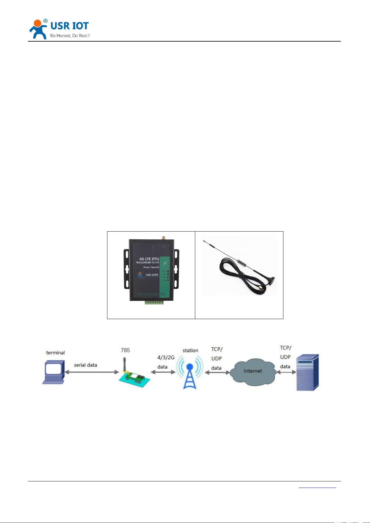
If you have purchased it, you will have the following accessories:
Figure 1 accessories
Data flow topology:
Figure 2 data flow topology
Before testing, please do the hardware connection as shown below.
Page 5
USR-G785-E User Manual Technical Support: h.usriot.com
Jinan USR IOT Technology Limited www.usriot.com
5
1.2. Data Transmission Test
1.2.1. Initial Parameters
Work mode
Network data transmission
Server address
test.usr.cn
Server port
2317
Serial parameters
115200,8,1,None
Command port
RS232
Table 1 default parameters
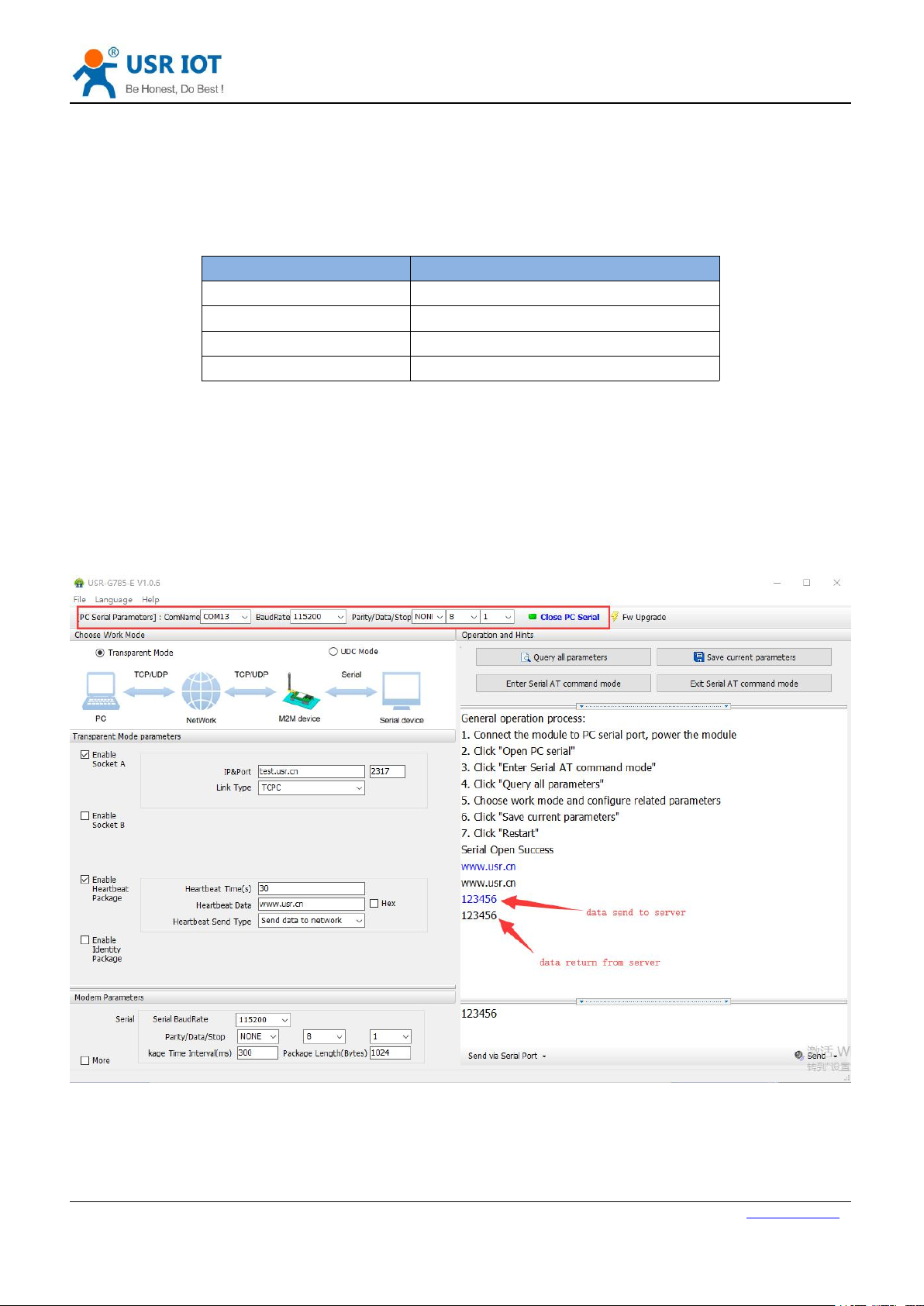
1. Connect to the computer serial port with the above connection mode. To set up the software, first select RS232's
serial number, baud rate and other parameters, and open the serial port.
Note: please keep the factory parameters during this test.
2. Power supply USR-G785-E with the power adapter configured by our company. POWER lights turn on, WORK
lights flicker, wait for GPRS and LINKA lights to turn on, proceed to the next step. Please refer to the following
chapters for instructions.
3. When the LINKA lights up, send data to the module through RS232 serial port, for example, send "www.usr.cn",
later in the software receiving window, receive "www.usr.cn", which is returned by the test server, the test is successful.
Figure 3 setup software
Page 6
USR-G785-E User Manual Technical Support: h.usriot.com
Jinan USR IOT Technology Limited www.usriot.com
6
2.Product Overview
2.1. Product Introduction
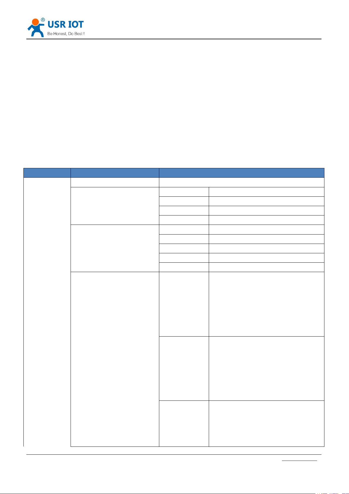
2.2. Module Default Parameters
Item
Index
Wireless
parameters
Wireless standard
TDD-LTE,FDD-LTE,WCDMA,GSM
Standard frequency range
TDD-LTE
B38/B40/B41
FDD-LTE
B1/B3/B5/B7/B8/B20
WCDMA
B1/B5/B8
GSM
B3/B8
Transmitting power
TDD-LTE
Class 3 (23dBm±2dB)
FDD-LTE
Class 3 (23dBm±2dB)
WCDMA
Class 3 (24dBm+1/-3dB)
GSM Band8
Class 4 (33dBm±2dB)
GSM Band3
Class 1 (30dBm±2dB)
Technical specifications
LTE
Maximum support for non-CA CAT 4
Supporting 1.4~20MHz RF bandwidth
Downlink support for multi-user MIMO
TDD: maximum up 35 Mbps,
maximum down 130 Mbps
FDD: Maximum upstream 50 Mbps,
maximum downstream 150 Mbps
WCDMA
Supports 3GPP R8 dc-hspa +
Supports 16-qam, 64_QAM and
QPSK modulation
3GPP R6 CAT6 HSUPA: maximum
uplink rate 5.76Mbps
3GPP R8 CAT24 dc-hspa + : the
maximum downlink rate is 42Mbps
GSM
R99: CSD transmission rate: 9.6
KBPS,14.4 KBPS
GPRS: supports GPRS multi-slot
class 12(default 12)
Coding formats: cs-1 / cs-1 / cs-3 and
USR-G785-E is the M2M product launched in 2018. European band .The software has perfect functions and covers
most of the conventional application scenarios. Users can realize two-way data transparent transmission from serial
port to network by simple settings. It also supports custom register packages, heartbeat packages, two-way Socket
connections.
Table 2 default parameters
Page 7
USR-G785-E User Manual Technical Support: h.usriot.com
Jinan USR IOT Technology Limited www.usriot.com
7
cs-4
Maximum 4 RX slots per frame
EDGE:
Support EDGE multi-slot class
12(default 12)
Antenna options
SMA interface
Hardware
parameters
Data interface
RS232:2400bps - 115200bps
RS485:2400bps - 115200bps
Working voltage
DC 9V~36V
Working current
Average 60ma-86ma Max: 175mA 12V
Working temperature
-40℃- 70℃
Storage temperature
-45℃- 90℃
Size
96.5×70×25mm
Software
parameters
Work mode
Transparent transmission mode, UDC mode.
Set command
AT+ command
Network protocol
TCP/UDP/DNS
Maximum TCP connection
number
2
User configuration
Serial AT command, net AT command,message AT
command
Customer application
software
Support customized application software
Software
function
Domain name resolution
DNS
Support
Simple transmission mode
Support TCP Client/ UDP Client
Heartbeat
Support
RFC2217 similar
Support
Registration package
mechanism
Support custom /ICCID/IMEI register package
2.3. Hardware Description
Unit:mm
Page 8

USR-G785-E User Manual Technical Support: h.usriot.com
Jinan USR IOT Technology Limited www.usriot.com
8
Figure 4 size
Page 9

USR-G785-E User Manual Technical Support: h.usriot.com
Jinan USR IOT Technology Limited www.usriot.com
9
2.4. Interface Introduce
3.Product Function
Figure 5 USR-G785-E interface
This chapter introduces the functions of USR-G785-E. The following diagram is a block diagram of the function of
the module. It can help you to have a general understanding of the product.
Page 10

USR-G785-E User Manual Technical Support: h.usriot.com
Jinan USR IOT Technology Limited www.usriot.com
10
Figure 6 product function
Page 11

USR-G785-E User Manual Technical Support: h.usriot.com
Jinan USR IOT Technology Limited www.usriot.com
11
3.1. Work Mode
3.1.1.Net Transparent Transmission Mode
3.1.1.1. Mode Declaration
Command name
Command function
Default parameters
AT+WKMOD
Query / setup work mode
"NET"
AT+SOCKA
Query / setup socket A parameter
"TCPC","test.usr.cn",2317
AT+SOCKB
Query / setup socket B parameter
"TCPC","test.usr.cn",2317
AT+SOCKAEN
Query / setup whether to enable
socket A
"on"
Figure 7 net transparent transmission mode
In this mode, the serial port device can send data to the specified server on the network through this module.
The module can also accept data from the server and forward the information to the serial port device.
Users do not need to pay attention to the data conversion process between serial port data and network packets,
only through simple parameter settings, data transparent communication between serial port devices and
network servers can be achieved.
This module supports two Socket connections, Socket A and Socket B, which are independent of each other.
Socket A supports TCP Client and UDP Client. Socket B support TCP Client and UDP Client
Table 3 AT commands
Page 12

Jinan USR IOT Technology Limited www.usriot.com
12
AT+SOCKBEN
Query / setup whether to enable
socket B
"off"
AT+SOCKALK
Query socket A connection state
"off"
AT+SOCKBLK
Query socket B connection state
"off"
Setting up software schematic diagram:
USR-G785-E User Manual Technical Support: h.usriot.com
Figure 8 setting up software schematic diagram
Page 13

USR-G785-E User Manual Technical Support: h.usriot.com
Jinan USR IOT Technology Limited www.usriot.com
13
3.1.2.UDC Mode
3.1.2.1. Mode Description
Command name
Command function
Default parameter
AT+WKMOD
Query / setup work mode
"NET"
AT+UDCID
Query/setup protocol transparent device ID
12345678901
AT+SOCKA
Query / setup socket A parameter
"TCPC","test.usr.cn",2317
AT+SOCKB
Query / setup socket B parameter
"TCPC","test.usr.cn",2317
AT+SOCKAEN
Query / setup whether to enable socket A
"on"
AT+SOCKBEN
Query / setup whether to enable socket B
"off"
AT+SOCKALK
Query socket A connection state
"off"
Figure9 UDC mode
In this mode, the user's terminal device can send the request data to the specified HTTP server through this
module, then the module receives the data from the HTTP server, parses the data and sends the results to the
serial port device.
Users do not need to pay attention to the data conversion process between serial port data and network packets,
only through simple parameter settings, can realize the serial port device to HTTP server data request.
Table 4 AT commands
Page 14

Jinan USR IOT Technology Limited www.usriot.com
14
AT+SOCKBLK
Query socket B connection state
"off"
Setting up software schematic diagram:
3.2. Serial Port
3.2.1.Basic Parameters
Item
Parameter
Baud rate
2400,4800,9600,19200,38400,57600,115200
Data bit
8
Stop bit
1,2
Check bit
NONE
EVEN
ODD
Flow control
RS 232: NFC,CRTS
RS485:None
USR-G785-E User Manual Technical Support: h.usriot.com
Figure10 UDC mode
Table 5 serial port basic parameters
Page 15

USR-G785-E User Manual Technical Support: h.usriot.com
Jinan USR IOT Technology Limited www.usriot.com
15
3.2.2.Frame Forming Mechanism
3.2.2.1. Time Trigger
3.2.2.2. Length Trigger
3.2.3.RFC2217 Similar Function
The packing time can be set from 300ms~60000ms. Default is 300ms.Users can send AT+UARTFT=<time>
to set.
The schematic diagram is as follows:
Figure11 frame forming mechanism
The packing length can be set from 1~1000, default is 1000.
Users can send AT+UARTFL=<length>.
The schematic diagram is as follows:
Figure12 frame forming mechanism
Note: The serial port receives 1000 bytes of cache, and the packet will be lost if the single packet exceeds 1000
bytes.
This function is similar to RFC2217 function, dynamically modifying serial port parameters from the network
side. Sending data conforming to a specific protocol from the network side can modify the parameters of the
serial port in real time. This modification is only temporary. After the module restarts, the original parameters
can be restored.
Page 16

USR-G785-E User Manual Technical Support: h.usriot.com
Jinan USR IOT Technology Limited www.usriot.com
16
3.3. Characteristic Function
3.3.1.Registration Package Function
Figure13 schematic diagram of RFC2217 similar function logic
Page 17

USR-G785-E User Manual Technical Support: h.usriot.com
Jinan USR IOT Technology Limited www.usriot.com
17
Command name
Command function
Default parameter
AT+ REGEN
Query / settings enable registration package
"off"
AT+ REGTP
Query / settings register package content type
"USER"
AT+ REGDT
Query / settings custom registration information
"7777772E7573722E6
36E"
AT+ REGSND
Query / settings register packet sending mode
"DATA"
Figure14 schematic diagram of registration function
Under the network pass through mode, users can send register packets from modules to the server.
Registered packages are designed to enable the server to identify the data source device, or as a password
to obtain authorization for server functionality. Registered packets can be sent when the module establishes a
connection with the server, and can also be spliced into the registration package data at the front end of each
packet as a packet. The data of the registration package can be ICCID code, IMEI code, or custom
registration data.
Table 6 AT commands
Setting up software schematic diagram:
Figure15 setting up software schematic diagram
Page 18

USR-G785-E User Manual Technical Support: h.usriot.com
Jinan USR IOT Technology Limited www.usriot.com
18
3.3.2.Heartbeat Packet
Command name
Command function
Default parameter
AT+ HEARTEN
Query / settings enable heartbeat package
"on"
AT+ HEARTDT
Query / settings heartbeat data
"7777772E7573722E636E"
AT+ HEARSND
Query / settings heartbeat packet send type
"NET"
AT+ HEARTTM
Query / settings heartbeat packet interval
10
Figure16 heartbeat packet
In the network transmission mode, user can send the heartbeat package from the module. Heartbeat packets
can be sent to the server side of the network, or to the device port of the serial port.
Because KEEP-ALIVE function is only used to keep online, but it can’t detect machine power outages,
network wire pull-out, firewalls, or other disconnection, and the logic layer processing disconnection will be
very complex. So we choose the mechanism of sending heartbeat to the network to detect whether the
connection between the module and the server is normal.
In applications where the server sends fixed query instructions to the device, in order to reduce traffic, users
can choose to send heartbeat packets (query instructions) to the serial port device instead of sending query
instructions from the server.
Table 7 AT commands
Setting up software schematic diagram:
Page 19

USR-G785-E User Manual Technical Support: h.usriot.com
Jinan USR IOT Technology Limited www.usriot.com
19
3.3.3.Indicator Status
Indicator name
Function
Status
POWER
Power on or not
on
WORK
Work normal or not
flicker
NET
Net status indicator
on
LINKA
Socket A connection instruction
on
3.3.4.Firmware Upgrade
3.3.5.Restore to The Factory Settings
Figure17 setting up software schematic diagram
There are four indicator lights on the G785, namely POWER, WORK, NET and LINKA. The status of the
indicator is as follows:
Table 12 indicator status
USR-G785-E supports upgrading through serial ports.
Restore the factory default parameters. After power on, press the Reload key for 3~15S, and then release,
the device parameters can be restored to the factory default parameters.
Page 20

USR-G785-E User Manual Technical Support: h.usriot.com
Jinan USR IOT Technology Limited www.usriot.com
20
4.Parameter Setting
4.1. AT Commands Setting
4.1.1.Setup Software
4.1.2.Net AT Command
Figure18 setting up software schematic diagram
Explain:
1. Software serial port parameter setting area.
2. Work mode selection area, select module work and which mode.
3. Special feature parameter setting area, set up the special function related parameters of the module.
4. Set the basic global parameters of the module.
5. The command sending button can be sent from the input instruction.
6. Input box, from the input instruction text box.
7. The receiving box receives the return information from the module.
8. Commonly used instruction buttons, click to enter the commonly used AT commands.
Network AT command is the way to set and query parameters by sending passwords and AT instructions through the
network while working in the transmission mode.
Page 21

USR-G785-E User Manual Technical Support: h.usriot.com
Jinan USR IOT Technology Limited www.usriot.com
21
4.1.3.SMS AT Command
5.AT Commands
Error
Implication
Err1
Wrong format, need AT+
Err2
Wrong command
Err3
Not meet the format of the query or Settings
Err4
Wrong parameters or number
NO.
Command
Function
Effective
immediately
Management command
1ATTest command
Y
2HHelp information
Y
3ZModule reboot
Y
4EDoes query / settings open instruction recall
Y
5
ENTM
Exit command mode
Y
6
WKMOD
Query / setup work mode
N
7
CMDPW
Query / set command password
Y
8
STMSG
Query / set module startup information
N
9
NWINFO
Query network format
Y
10
CSQ
Query the current signal strength information of the device
Y
11
CIP
Query the IP of G785
Y
Configuration parameter command
12
RELD
Restore user default settings
Y
13
CLEAR
Restore original factory settings
Y
14
CFGTF
Save the current settings as default settings.
Y
Information query command
15
VER
Query version information
Y
16
HDVER
Query hardware version
Y
17SNQuery SN code
Y
18
ICCID
Query ICCID code
Y
19
IMEI
Query IMEI code
Y
Serial port parameter command
20
UART1
Query / set uart1 parameters
N
21
UART2
Query / set uart2 parameters
N
22
UARTFT
Query/set serial port package time
N
SMS AT instruction is that we can use SMS to query and configure the parameters of the module.
Table 9 error code
Table 10 AT commands
Page 22

USR-G785-E User Manual Technical Support: h.usriot.com
Jinan USR IOT Technology Limited www.usriot.com
22
23
UARTFL
Query/set serial port package length
N
24
CMDPT
Query/set RS232 or RS485 work as command port
N
25
RFCEN
Query/set enable/disable RFC2217 similar function
Y
Net command
26
APN
Query / set APN information
N
27
SOCKA
Query / setup socket A parameter
N
28
SOCKB
Query / setup socket B parameter
N
29
SOCKAEN
Query / setup whether to enable socket A
N
30
SOCKBEN
Query / setup whether to enable socket B
N
31
SOCKALK
Query socket A connection state
Y
32
SOCKBLK
Query socket B connection state
Y
33
RSTIM
Query/set the reboot time without data transmission
Y
Register command
34
REGEN
Query / settings enable registration package
N
35
REGTP
Query / settings register package content type
N
36
REGDT
Query / settings custom registration information
N
37
REGSND
Query / settings register packet sending mode
N
38
UDCID
Query/set the device ID when work at UDC mode
N
Heartbeat command
39
HEARTEN
Query / settings enable heartbeat package
N
40
HEARTDT
Query / settings heartbeat data
N
41
HEARTSND
Query / settings heartbeat packet sending type
N
42
HEARTTM
Query / settings heartbeat packet interval
N
SMS command
43
CISMSSEND
Send SMS
Y
Note: the details of AT commands, please view the software design manual of the module.
Page 23

USR-G785-E User Manual Technical Support: h.usriot.com
Jinan USR IOT Technology Limited www.usriot.com
23
Edition
Describe
V1.0.2
2019-02-11 establish
V1.0.3
2019-02-21 modify the error description
6.Contact Us
Company: Jinan USR IOT Technology Limited
Address: Floor 11, Building 1, No. 1166 Xinluo Street, Gaoxin District, Jinan, Shandong, 250101, China
Web: www.usriot.com
Support: h.usriot.com
Email: sales@usr.cn
Tel: 86-531-88826739/86-531-55507297
7.Disclaimer
This document provide the information of USR-G785-E products, it hasn’t been granted any intellectual property
license by forbidding speak or other ways either explicitly or implicitly. Except the duty declared in sales terms
and conditions, we don’t take any other responsibilities. We don’t warrant the products sales and use explicitly
or implicitly, including particular purpose merchantability and marketability, the tort liability of any other patent
right, copyright, intellectual property right. We may modify specification and description at any time without
prior notice.
8.Update History
 Loading...