

Page 1

USR-DR504-E User Manual www.usriot.com
Jinan USR IOT Technology Limited1www. usriot. com
USR-DR504-E Software Manual
Version: V1.0.2
Page 2

USR-DR504-E User Manual www.usriot.com
Jinan USR IOT Technology Limited Tech Support: h.usriot.com
2
Function
Supports accessing to European bands.
Supports 2 socket connections , support TCP Server , TCP Client and UDP Client.
Support remote upgrade, hardware watchdog.
Each connection supports buffering 5 packets of serial port data.
Supports sending the register package and heartbeat package data
Supports setting DTU parameters by serial port /SMS/network.
Supports base station positioning function.
Supports Modbus protocol conversion, modbus RTU to Modbus TCP.
Supports base station positioning.
Supports multiple work mode: transparent transmission mode and SMS mode.
Supports basic commands.
Supports remote upgrade, keep the firmware up to date.
Supports sending English SMS.
Page 3

USR-DR504-E User Manual www.usriot.com
Jinan USR IOT Technology Limited Tech Support: h.usriot.com
3
Contents
USR-DR504-E Software Manual..........................................................................................................................................1
Function................................................................................................................................................................................. 2
1. Product overview............................................................................................................................................................... 6
1.1. Product Overview................................................................................................................................................... 6
2. Product function................................................................................................................................................................ 7
2.1. Work mode............................................................................................................................................................. 8
2.1.1. Net transparent transmission mode
2.1.2. SMS mode
2.2. Serial port..............................................................................................................................................................12
2.2.1. Basic parameter
2.2.2. Frame forming mechanism
2.3. Characteristic function..........................................................................................................................................14
2.3.1. Registration package function
2.3.2. Heartbeat packet
2.3.3. USR Cloud
2.3.4. Basic Station Position
2.3.5. Modbus protocol conversion
2.3.6. Indicator Status
Form 2.3.6-1 Indicators
2.3.7. Restore to the factory default settings
2.3.8. Firmware Upgrade
3. Parameter setting.............................................................................................................................................................27
3.1. Setup by serial port...............................................................................................................................................27
3.1.1. Setup software
3.1.2. AT command setting
3.1.3. Serial AT command
3.1.4. Network AT command
3.1.5. SMS AT command
3.1.6. Command format
3.1.7. AT commands
..........................................................................................................................................................
.................................................................................................................................................
................................................................................................................................
2. 2. 2. 1 Time trigger...................................................................................................................................13
2. 2. 2. 2 Length trigger................................................................................................................................13
...............................................................................................................................................
..........................................................................................................................................................
.........................................................................................................................................
..................................................................................................................................................
................................................................................................................................................
.............................................................................................................................................
2.3.8.1. Upgrade by serial port.................................................................................................................... 24
2.3.8.2. Remote update...............................................................................................................................26
...................................................................................................................................................
..........................................................................................................................................
............................................................................................................................................
.......................................................................................................................................
..............................................................................................................................................
..............................................................................................................................................
3. 1. 6. 3 The Answer Format in Command................................................................................................. 32
3. 1. 6. 4 Special symbols.............................................................................................................................33
....................................................................................................................................................
1. AT............................................................................................................................................................. 35
2. AT+H.........................................................................................................................................................35
3. AT+Z......................................................................................................................................................... 35
4. AT+E......................................................................................................................................................... 35
5. AT+ENTM................................................................................................................................................. 36
6. AT+WKMOD.............................................................................................................................................36
....................................................................................................................
...........................................................................................................................
............................................................................................................................
..............................................................................................................
11
12
13
14
16
19
21
22
24
24
24
24
27
28
29
30
30
31
33
8
Page 4

USR-DR504-E User Manual www.usriot.com
Jinan USR IOT Technology Limited Tech Support: h.usriot.com
4
7. AT+CMDPW..............................................................................................................................................36
8. AT+STMSG................................................................................................................................................37
9. AT+RSTIM.................................................................................................................................................37
10. AT+CSQ.................................................................................................................................................. 37
11. AT+SYSINFO............................................................................................................................................38
12. AT+UCPIN...............................................................................................................................................39
13. AT+RELD.................................................................................................................................................39
14. AT+CLEAR...............................................................................................................................................40
15. AT+CFGTF...............................................................................................................................................40
16. AT+VER...................................................................................................................................................40
17. AT+SN.....................................................................................................................................................40
18. AT+ICCID................................................................................................................................................ 40
19. AT+IMEI..................................................................................................................................................41
20. AT+CIP....................................................................................................................................................41
21. AT+LBS................................................................................................................................................... 41
22. AT+PING.................................................................................................................................................41
23. AT+UART................................................................................................................................................ 42
24. AT+UARTFT.............................................................................................................................................42
25. AT+UARTFL.............................................................................................................................................43
26. AT+APN.................................................................................................................................................. 43
27. AT+SOCKA.............................................................................................................................................. 43
28. AT+SOCKB.............................................................................................................................................. 44
29. AT+SOCKAEN..........................................................................................................................................44
30. AT+SOCKBEN..........................................................................................................................................45
31. AT+SOCKALK...........................................................................................................................................45
32. AT+SOCKBLK...........................................................................................................................................45
33. AT+SOCKATO.......................................................................................................................................... 46
34. AT+SOCKBTO..........................................................................................................................................46
35. AT+SOCKRSTIM...................................................................................................................................... 46
36. AT+MODBUSEN......................................................................................................................................46
37. AT+REGEN.............................................................................................................................................. 47
38. AT+REGTP...............................................................................................................................................47
39. AT+REGDT.............................................................................................................................................. 48
40. AT+REGSND............................................................................................................................................48
41. AT+CLOUD..............................................................................................................................................48
42. AT+HEARTEN..........................................................................................................................................49
43. AT+HEARTDT.......................................................................................................................................... 49
44. AT+HEARTSND........................................................................................................................................50
45. AT+HEARTTM.........................................................................................................................................50
46. AT+DSTNUM.......................................................................................................................................... 50
47. AT+SMSFLT.............................................................................................................................................51
48. AT+CISMSSEND...................................................................................................................................... 51
4. Contact Us........................................................................................................................................................................52
5. Disclaimer........................................................................................................................................................................ 52
Page 5

USR-DR504-E User Manual www.usriot.com
Jinan USR IOT Technology Limited Tech Support: h.usriot.com
5
6. Update History................................................................................................................................................................. 52
Page 6

USR-DR504-E User Manual www.usriot.com
Jinan USR IOT Technology Limited Tech Support: h.usriot.com
6
Parameter
Item
Index
Wireless
Parameters
Wireless standard
FDD-LTE, TDD-LTE, HSPA+/WCDMA, GSM/GPRS/EDGE
Standard frequency range
FDD-LTE
Band 1/2/3/5/7/8/20
TDD-LTE
Band 38/40/41
HSPA+/WCDMA
Band 1/2/5/8
GSM/GPRS/EDGE
Band 2/3/5/8
Transmitting power
TDD-LTE
+23dBm(Power class 3)
FDD-LTE
+23dBm(Power class 3)
WCDMA
+24dBm(Power class 3)
EDGE Band8
+27dBm(Power class E2)
EDGE Band3
+26dBm(Power class E2)
GSM Band8
+33dBm(Power class 4)
GSM Band3
+30dBm(Power class 1)
Technical specifications
LTE
3GPP R10 CAT4 Downward 150 Mbps , Uplink 50
Mbps
HSPA+
Downward 42 Mbps , Uplink 5. 76 Mbps
EDGE
Downward 236. 8 kbps , Uplink 236. 8 kbps
GPRS
Downward rate 85. 6 kbps Uplink rate 85. 6 kbps
Antenna options
SMA interface
Hardware
parameters
Data interface
RS485: 2400bps - 230400bps
Working voltage
DC 9V~36V
Working current
Average:83.69mA- 98.26mA@12V Max:232.91mA@12V
Working temperature
-30℃ - 75℃
Storage temperature
-40℃ - 95℃
Size(mm)
28*64.7*109.7(L*W*H)
Software
Work mode
Transparent transmission mode, SMS mode
Setting command
AT+Command
Network protocol
TCP/UDP
Maximum TCP connection
number
2
1. Product overview
1.1. Product Overview
USR-DR504-E is the M2M product launched in 2019 with the characteristics of high speed and low latency.
European band. The software has perfect functions and covers most common application scenarios. It can realize
two-way data transparent transmission from serial port to network by simple settings. And supports SMS mode, custom
register packages, heartbeat packages , support 2 way socket connections, support TCP Server, support access USR
cloud , support remote upgrade.
Figure 1 DTU default parameters
Page 7

USR-DR504-E User Manual www.usriot.com
Jinan USR IOT Technology Limited Tech Support: h.usriot.com
7
parameters
User configuration
Serial AT command , Net AT command , Message AT command
Customer application
software
Support customized application software
Software
function
Domain name solution
DNS
Support
Modbus protocol
conversion
Support
Simple transmission
Support TCP Client/TCP Server/UDP Client
Message functions
Support
Heartbeat package
Support
Registration package
mechanism
Custom registration package/ICCID /IMEI
User-cloud service
Support
Remote update
Support
Form1. 1-1 Basic Parameters
2. Product function
This chapter introduces the functions of DR504-E, the following diagram is a block diagram the function of the
module. It can help you to have a general understanding of the product.
Diagram 2-1 Product Function
Page 8

USR-DR504-E User Manual www.usriot.com
Jinan USR IOT Technology Limited Tech Support: h.usriot.com
8
2.1. Work mode
USR-DR504-E module has three working modes: network transmission mode and SMS transmission mode.
Network transmission mode: the data is sent to the network server directly through the serial port of the module
without any processing or modification.
SMS transmission mode: data enters the module through serial port and is processed by the module and sent to
the target mobile phone number.
2.1.1. Net transparent transmission mode
Diagram 2. 1. 1-1 Net transparent transmission mode
In this mode, the user's serial device can directly send data to the specified network server through the DR504-E
module.
The module can also receive data from the server and directly forward the received information to the serial port
device.
In this mode, users do not need to pay attention to the data conversion process between serial port data and
network data packets. They only need to set simple parameters to realize the transparent transmission of data between
serial port devices and network servers.
The module supports 2 socket connections, Socket A and Socket B, which are independent of each other. Only
Socket A supports as TCP Client, TCP Server and UDP Client. Socket B only supports TCP Client and UDP Client.
Under the TCP server mode, It supports 3 clients connections at max. Because the conventional operator network
can not be accessed through the external network, so for the Server function need to use a dedicated APN card.
Set DR504-E work at TCP client by AT commands:
1. Set the working mode to net transparent transmission:
Page 9

USR-DR504-E User Manual www.usriot.com
Jinan USR IOT Technology Limited Tech Support: h.usriot.com
9
AT+WKMOD=NET
2. Enable socket A:
AT+SOCKAEN=ON
3. Setup remote IP and port:
AT+SOCKA=TCPC,test. usr. cn,2317
4. Setup APN.
E. g: APN is CMNET, username is empty, password is empty, authentication method is NONE:
AT+APN=CMNET,,,0
5. Reboot:
AT+Z
Set DR504-E work at TCP Sever by AT commands:
1. Set the work mode to net transparent mode:
AT+WKMOD=NET
2. Enable socket A:
AT+SOCKAEN=ON
3. Set socket A as TCP Server, local port 2317, IP has no reference meaning in Server:
AT+SOCKA=TCPS,test. usr. cn,2317
4. Setup APN. E. g: APN:CMNET, username: empty, password: empty, authentication method: NONE:
AT+APN=CMNET,,,0
5. Reboot:
AT+Z
Page 10

USR-DR504-E User Manual www.usriot.com
Jinan USR IOT Technology Limited Tech Support: h.usriot.com
10
Diagram 2.1.1-1 Software schematic diagram
1. Open the setup software. Set the Serial port parameters according to the actual situation and click "Open PC Serial".
2. Click "Enter Serial AT command mode" and wait for the device to enter AT command configuration mode.
3. Click "Query all parameters" and wait for obtaining all current parameters.
4. In the "Choose Work Mode" , select "Transparent Mode".
5. Set "IP&Port" to test. usr. cn and 2317.
6. Check "More".
7. Set the APN parameter: CMNET,,,0. E. g: APN: CMNET, username: empty, password: empty, authentication
method :NONE.
8. Click "Save current parameters".
9. Click the "Restart" button to restart the module.
Page 11

Jinan USR IOT Technology Limited Tech Support: h.usriot.com
11
2.1.2. SMS mode
USR-DR504-E User Manual www.usriot.com
Diagram 2.1.3-1 SMS transmission mode diagram
In this mode, user's serial device can send SMS to the specified mobile phone and receive SMS from any mobile
phone. User can decide whether to transmit the data of the specified mobile phone to the serial device through
Settings.
Users do not need to pay attention to the data conversion process between serial port data and SMS. They only
need to set simple parameters to realize transparent data communication between mobile phones and serial port
devices.
If the user's device is a serial port device and is placed in a remote place, this DTU can be used to realize this
function when the user wants to check the running status of the device or control the running parameters of the device
by sending and receiving SMS messages.
Setup by AT commands:
1. Set work mode to SMS mode:
AT+WKMOD=SMS
2. Set the target mobile phone number to 10086. E. g:10086:
AT+DSTNUM=10086
3. Restart the module:
AT+Z
Note: 1. The target phone number of SMS should be added with the international number;
2. When non-target mobile phone number filtering is enabled, the non-target mobile phone number can still
query or set parameters;
3. When a SMS longer than 140 bytes is sent to the device, the received SMS will be incomplete.
Setting by the software:
Page 12

USR-DR504-E User Manual www.usriot.com
Jinan USR IOT Technology Limited Tech Support: h.usriot.com
12
Project
Parameter
Diagram 2.1.3-1 Software Schematic
1. Open the setup software. Setting the serial port parameters according to the actual situation and click "Open PC
Serial".
2. Click "Enter Serial AT command mode" and wait for the device to enter AT command configuration mode.
3. Click "Query all parameters" and waiting for obtaining all current parameters.
4. In the "choose work Mode" , select "SMS Mode".
5. Set the target mobile phone number as "10086". E. g: 10086.
6. If you need to filter SMS from other mobile numbers, open "Only receive SMS from source number".
7. Click "Save current parameters" to set and save all parameters.
8. Click "Restart" to restart the module.
2.2. Serial port
2.2.1. Basic parameter
Figure 2
Serial port basic parameter
Page 13

USR-DR504-E User Manual www.usriot.com
Jinan USR IOT Technology Limited Tech Support: h.usriot.com
13
Baud rate
2400,4800,9600,14400,19200,28800,33600,38400,57600
,115200,230400,460800
Data bit
8
Stop bit
1,2
Check bit
NONE
EVEN
ODD
Form 2.2.1-1 Serial Parameters
2.2.2. Frame forming mechanism
2. 2. 2. 1 Time trigger
When DR504-E receives data from the UART, it continuously checks the interval of two adjacent bytes. If the
interval time is greater or equal to a certain "time threshold", then a frame is considered finished, otherwise the data is
received until greater or equal to the packet length byte set. This frame is sent to the network as a TCP or UDP packet.
The "time threshold" here is the time between packages. The range of settable is 100ms~60000ms. Factory default:
100ms.
This parameter can be set by AT command, AT+UARTFT=<time>.
Diagram 2.2.2.1-1 Time trigger
2. 2. 2. 2 Length trigger
When DR504-E receives data from the UART, it constantly checks the number of bytes received. If the number of
bytes received is equal to a certain "length threshold", a frame is considered to have ended, otherwise the packaging
time is waiting for the end. This frame is sent to the network as a TCP or UDP packet. The "length threshold" here is the
package length. The settable range is 100~1000. Factory default 1000.
Note: when using “command password +AT command” function, the package length must be larger than the “command
password +AT command”, otherwise AT command is invalid
This parameter can be set by AT command, AT+UARTFL=<length>.
Page 14

USR-DR504-E User Manual www.usriot.com
Jinan USR IOT Technology Limited Tech Support: h.usriot.com
14
Command name
Command function
Default parameter
AT+REGEN
Query/setting enable registration package
OFF
AT+REGTP
Query/setting the type of registration package content
USER
2.3. Characteristic function
2.3.1. Registration package function
Diagram 2.2.2.2-1 Length Trigger
Diagram 2.3.1-1 Registration Schematic Diagram
In the network transparent mode, the user can choose to have the module send the registration package to the
server. Registered package is intended to allow the server to identify the data from which device or to use it as a
password to obtain authorization for the server's functions. The registration package can be sent when the module
establishes a connection with the server, or be added at the forefront of each data packet to form a data packet to be
sent to the network. The data of registration package can be ICCID code, IMEI code, USR-cloud registration package, or
custom registration data.
ICCID: Unique SIM identification code, for applications based on SIM card identification.
IMEI: The unique identification code of the Internet module, which is mainly used in device identification, has
nothing to do with SIM.
CLOUD: The identification code based on the USR-cloud, can easily use the USR-Cloud by setting the relevant
parameters.
USER: User-defined data.
Figure 3 AT commands
Page 15

Jinan USR IOT Technology Limited Tech Support: h.usriot.com
15
AT+REGDT
Query/setting custom registration information
7777772E7573722E636E
AT+REGSND
Query/setting the mode of registration package for
sending
DATA
AT commands setting:
1. Enable register package function:
AT+REGEN=ON
2. Setup custom the register package:
AT+REGTP=USER
3. Setup the contents:
AT+REGDT=7777772E7573722E636E
4. Setup the type of register package:
AT+REGSND=DATA
5. Reboot:
AT+Z
Setting software schematic diagram:
USR-DR504-E User Manual www.usriot.com
Form 2.3.1-1 Related AT Command
Diagram 2.3.1-2 Software Schematic Diagram
Page 16

USR-DR504-E User Manual www.usriot.com
Jinan USR IOT Technology Limited Tech Support: h.usriot.com
16
Command name
Command function
Default parameter
AT+HEARTEN
Query/Setting enable heartbeat packet
ON
AT+HEARTDT
Query/Setting heartbeat data
7777772E7573722E636E
AT+HEARTSND
Query/Setting heartbeat packet send type
NET
AT+HEARTTM
Query/Setting heartbeat packet interval
30
1. Open the dedicated setup software. Set the Serial port parameters according to the actual situation and click "Open
PC Serial".
2. Click "Enter Serial AT command mode" and wait for the device to enter AT command configuration mode.
3. Click "Query all parameters" and wait for obtaining all current parameters.
4. In the "Choose Work Mode" column, select "Transparent Mode".
5. Set the parameter of SocketA.
6. Enable identity package and set various parameters.
7. Set APN parameters.
8. Click "Save current parameters" to save all parameters.
9. Restart the module.
2.3.2. Heartbeat packet
Diagram 2.3.2-1 Heartbeat schematic diagram
In the network transparent mode, user can send the heartbeat packet from the module to meet specific
requirements.
Heartbeat packet can be sent to the network side, also can be sent to the serial port device. The main purpose of
sending the heartbeat to the network is to keep the connection stable and reliable, to ensure the normal connection of
the module, and at the same time, to let the server know the online situation of the module through the heartbeat
packet.
In the application of fixed query commands sent by the server to the device, in order to reduce communication
traffic, user can choose to send heartbeat packet (query commands) to the serial port device instead of sending query
commands from the server, so as to save traffic and respond faster.
Figure 4 AT commands
Form 2.3.2-1 Related AT Command
AT commands setting :
Page 17

USR-DR504-E User Manual www.usriot.com
Jinan USR IOT Technology Limited Tech Support: h.usriot.com
17
1. Enable heartbeat function:
AT+HEARTEN=ON
2. Setup the contents of heartbeat packet:
AT+HEARTDT=7777772E7573722E636E
3. Setup the type of heartbeat packet:
AT+HEARTTP=NET
4. Setup the sending time:
AT+HEARTTM=30
4. Reboot:
AT+Z
Schematic diagram of setup software:
Page 18

USR-DR504-E User Manual www.usriot.com
Jinan USR IOT Technology Limited Tech Support: h.usriot.com
18
Diagram 2.3.2-2 Software Schematic Diagram
1. Open the dedicated setup software. Set the Serial port parameters according to the actual situation and click "Open
PC Serial".
2. Click "Enter Serial AT command mode" and wait for the device to enter AT command mode.
3. Click "Query all parameters" and wait for obtaining all current parameters.
4. In the "Choose Work Mode", select "Transparent Mode".
5. Set the parameters of SocketA.
6. Enable heartbeat package function and set various parameters.
7. Set APN parameters.
8. Click "Save current parameters" to set and save all parameters.
9. Restart the module.
Page 19

USR-DR504-E User Manual www.usriot.com
Jinan USR IOT Technology Limited Tech Support: h.usriot.com
19
Command name
Command function
Default Parameter
AT+CLOUD
To configure device ID(20 bytes), password (8 bytes)
"",””
2.3.3. USR Cloud
Diagram 2.3.3-1 USR-Cloud
USR-Cloud is mainly an open platform to solve the communication between devices and devices, devices and
upper computer (Android, IOS, PC). USR-Cloud is mainly used for transmission of data, The device can be accessed
without any modification to achieve remote transparent transmission of data. . USR-Cloud is suitable for remote
monitoring, Internet of things, Internet of vehicles, smart home and other fields, so our USR-DR504-E also supports
access to USR-Cloud. For more information about USR-Cloud, please visit http://console. usriot. com/.
Figure 5 Reference AT command
Form 2.3.3-1 USR-Cloud
AT commands setting:
1. Setup the work mode:
AT+WKMOD=NET
2. Enable socket A :
AT+SOCKAEN=ON
3. Setup SocketA parameters,
Address: clouddata. usriot. com, port: 15000
AT+SOCKA=TCPC,clouddata. usriot. com,15000
4. Set the ID of usr-cloud
(the ID and password can get from the usr-cloud website):
AT+CLOUD=01234567890123456789,13245678
5. Set the registration packet to usr-cloud:
AT+REGTP=CLOUD
6. Enable registration packet:
AT+REGEN=ON
7. Setup the registration sending mode :
AT+REGSND=LINK
8. Reboot:
AT+Z
Page 20

USR-DR504-E User Manual www.usriot.com
Jinan USR IOT Technology Limited Tech Support: h.usriot.com
20
Note: USR-cloud website :http://console. usriot. com/
Software schematic diagram:
Diagram 2.3.3-2 USR-Cloud
1. Open the dedicated setup software. Set the Serial port parameters according to the actual situation and click "Open
PC Serial".
2. Click "Enter Serial AT command mode" and wait for the device to enter AT command configuration mode.
3. Click "Query all parameters" and wait for obtaining all current parameters.
4. In the column "Choose Work Mode", select "Transparent Mode".
5. Set the parameters of SocketA, "IP&Port" is clouddata. usriot. com and 15000, and the connection type is "TCPC".
6. Open the "Enable Identity Package" function, the registry sending option is "Send registers data when socket
connects", registered type is "Cloud (for USR Cloud)", open the function of Cloud, and set the parameters (device ID and
the code need to log in to http://console. usriot. com/).
7. Set the parameters of APN.
8. Click "Save current parameters" to set and save all parameters.
9. Restart the module.
Page 21

USR-DR504-E User Manual www.usriot.com
Jinan USR IOT Technology Limited Tech Support: h.usriot.com
21
Command name
Command function
Default parameter
AT+LBS
Query station positioning information
Empty
2.3.4. Basic Station Position
USR-DR504-E supports LBS base station positioning function, and can obtain the general location of the equipment
through the operator's network, with a positioning accuracy of about 100 meters. Base station positioning information
is obtained through AT command, which can be used flexibly with serial AT and SMS AT command.
Form 2.3.4-1 Related AT Command
Note: This function does not obtain positioning information directly(for example, latitude and longitude
information), but base station location information. Users need to give this information to a third party, and the third
party will obtain a direct positioning information through calculation. Third-party location information services are
generally paid services. When the user tests, you can go to the URL to convert the actual location:
http://www. minigps. net/cellsearch. html(This URL is for testing only and does not guarantee site stability)
The query interface is shown below:
Diagram 2.3.4-1 Searching the Position
Click the query to get the converted location information
Diagram 2.3.4-2 Position
Page 22

USR-DR504-E User Manual www.usriot.com
Jinan USR IOT Technology Limited Tech Support: h.usriot.com
22
Command name
Command functions
Default parameter
AT+MODBUSEN
Query/Setting whether to enable Modbus
protocol conversion
OFF
2.3.5. Modbus protocol conversion
Diagram 2.3.5-1 Modbus Protocol Conversion Schematic Diagram
In the network transparent mode, if the terminal device transmits data through Modbus RTU protocol and the
server communicates through Modbus TCP protocol, user can turn on the function of DTU Modbus TCP/RTU protocol
internal conversion. After this function is enabled, DTU converts the Modbus TCP protocol data sent by the server into
Modbus RTU protocol and sends it to the terminal device, and converts the Modbus RTU protocol data sent by the
terminal device into Modbus TCP protocol and sends it to the server.
AT commnd setting method:
1. Set work mode to Transparent mode. :
AT+WKMOD=NET
2. Enable Socket A:
AT+SOCKAEN=ON
3. Set socket A to TCP Client:
AT+SOCKA=TCP,test. usr. cn,2317
4. Enable Modbus protocol conversion:
AT+MODBUSEN=ON
5. Restart the machine:
AT+Z
Setting software diagram:
Form 2.3.5-1 Related AT Command
Page 23

USR-DR504-E User Manual www.usriot.com
Jinan USR IOT Technology Limited Tech Support: h.usriot.com
23
Diagram 2.3.5-2 Setting software diagram
1. Open the dedicated setup software. Set the serial port parameters according to the actual situation and click "Open
PC Serial".
2. Click "Query all parameters", waiting to get all current parameters.
3. In the "Choose Work Mode" , check "Transparent Mode"
4. Set the parameters of SocketA
5. Check "MODBUS Change".
6. Set the APN parameters.
7. Click "Save current parameters" to set and save all parameters.
8. Click "Restart" to restart the module.
Page 24

USR-DR504-E User Manual www.usriot.com
Jinan USR IOT Technology Limited Tech Support: h.usriot.com
24
Indicator name
Indicator function
Status
POWER
Power indicator
Always on after power work normally
WORK
System operation indicator.
Flashing after system running
NET
Network status indicator
Always on after registering the network
LINKA
Socket A connection indicator
Always on after socket A is connected
LINKB
Socket B connection indicator
Always on after the socket B connected
TX
Serial port send the data
Light when there is data from serial port
RX
Serial port receive the data
Light when there is data received by the serial
port
First-level signal
Indicate the first level signal
strength
Always on when the signal strength reach the
first level
Second-level
Indicate the second level signal
strength
Always on when the signal strength reach the
second level
Third- level signal
Indicate the third level signal
strength
Always on when the signal strength reach the
third level
2.3.6. Indicator Status
There are ten indicators light on the DR504, PWR, WORK, NET, LINKA, LINKB, TX, RX, First-level signal strength,
second-level signal and third- level signal. The status represented by the indicator are as follows:
Figure 8 Indicator status
Form 2.3.6-1 Indicators
2.3.7. Restore to the factory default settings
After power on, press the Reload button for 3~15S and release it to restore the device parameters to factory
default parameters.
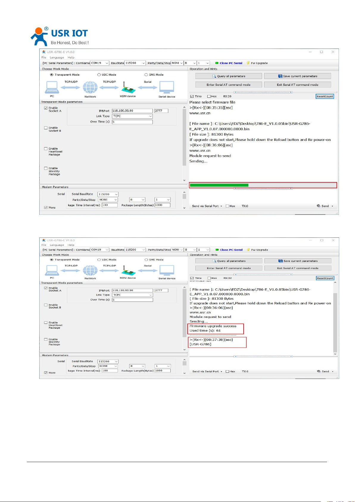
2.3.8. Firmware Upgrade
2.3.8.1. Upgrade by serial port
In order to reduce the complexity of firmware upgrade for users, USR-DR504-E has specially set up the firmware
upgrade with 232 ports. The steps are as follows:
(1) Set baud rate to 115200, no check bit, data bit 8, stop bit 1, open serial port, click firmware upgrade, and select
the firmware to be upgraded.
Page 25

USR-DR504-E User Manual www.usriot.com
Jinan USR IOT Technology Limited Tech Support: h.usriot.com
25
Diagram 2.3.8.1-1 Serial update Schematic Diagram
(2) As indicated, hold down the Reload pin and power USR-DR504-E at the same time.
Diagram 2.3.8.1-2 Serial Update Schematic Diagram
(3) After that, you can see that the firmware is being downloaded, release the Reload pin and wait for the update.
Page 26
USR-DR504-E User Manual www.usriot.com
Jinan USR IOT Technology Limited Tech Support: h.usriot.com
26
Diagram 2.3.8.1-3 Serial Update Schematic Diagram
(4) firmware update is completed and the device is restarted.
Diagram 2.3.8.1-1 Serial update Schematic Diagram
2.3.8.2. Remote update
Remote upgrade uses polling mode to query, and the server is requested once by default for 30 minutes to get
whether there is an upgrade demand. If the upgrade is needed, the firmware data will be downloaded from the server
for the upgrade; if not, the system will sleep and wait for the next round. The polling time of Fota upgrade can be set
through AT+FOTATIME with a range of 10~65535s.
Page 27

Jinan USR IOT Technology Limited Tech Support: h.usriot.com
27
3. Parameter setting
3.1. Setup by serial port
3.1.1. Setup software
USR-DR504-E User Manual www.usriot.com
Diagram 3.1.1-1 Setting Software
Description:
1. In PC serial parameter setting area, it is necessary to set parameters consistent with the current serial port of DTU,
otherwise it cannot communicate with DTU.
2. Working mode selection area, select the working mode of DTU.
3. In the parameter setting area of characteristic functions, set parameters related to DTU's featured functions
4. Global parameter area, setup DTU basic global parameters.
5. Common command button, click to send the self-input command.
6. Data receiving and display area, displaying the data sent and received.
7. Data sending area, input the data and click Send.
Page 28

USR-DR504-E User Manual www.usriot.com
Jinan USR IOT Technology Limited Tech Support: h.usriot.com
28
3.1.2. AT command setting
When the device works in either the network transparent mode, the device can switch to the "AT command
mode" by sending time-specific data to the serial port of the device.
When the operation is completed in "AT command mode", the device is sent specific commands to return to the
previous working mode.
Diagram 3.1.2-1 Time Line
Changing the timing of command mode:
In the figure above, the horizontal axis is the time axis, the data above the time axis is sent by the serial port device to
the device, and the data below the time axis is sent by the device to the serial port.
Time requirement:
T1> current serial port packaging interval (refer to AT+UARTFT)
T2 < current serial port packaging interval time (refer to AT+UARTFT)
T3 < current serial port packaging interval time (refer to AT+UARTFT)
T4 = current serial port packaging interval time (refer to AT+UARTFT)
T5 < 3 s
T6 = current serial port packaging interval time (refer to AT+UARTFT)
The time sequence of switching from Transparent transmission mode to AT Command mode:
Serial port device continuously sends "+++" to the device. After receiving "+++", the device will send an "a" to
the serial device. No data can be sent during a packaging cycle before sending "+++".
When the serial device receives 'a', a 'a' must be sent to the device within 3 seconds.
After receiving 'a', the device returns "+ok" and enter “temporary command mode”.
After receiving "+ok", the device has enter "temporary command mode" and now can send AT command to it
Time sequence of switching from AT command mode to network Transparent transmission mode”
The serial device sends "AT+ENTM" to the device.
After receiving the command, the device sends "OK" to the serial device and returns to the previous working
mode.
After the serial device receives "OK", it knows that the device has returned to its previous working mode.
Page 29

USR-DR504-E User Manual www.usriot.com
Jinan USR IOT Technology Limited Tech Support: h.usriot.com
29
3.1.3. Serial AT command
Serial AT command refers to the devices work in transparent mode and we do not need to switch to the command
mode. We can use the method of password and AT command to query and set parameters.
Generally, it is used when client equipment needs to query or modify parameters when DTU is running. It does not
need complicated +++ timing sequence to enter AT command mode, so as to quickly query or set parameters.
Diagram 3.1.3-1 Software Schematic
Query the current password , query/setting command: AT+CMDPW
Through the software can see the current command password is: www. usr. cn#
After the setting is completed, restart the module, and send www. usr. cn#AT+VER (note that there is an Enter at the
end of the string) from the serial port to the module.
After receiving the string, the module will return the response information.
Page 30

USR-DR504-E User Manual www.usriot.com
Jinan USR IOT Technology Limited Tech Support: h.usriot.com
30
Diagram 3.1.3-2 Set-Up Software
3.1.4. Network AT command
Network AT command refers to the way to set and query parameters by sending passwords and AT commands
through the network when working in transparent transmission mode.
Network AT command is similar to serial AT command. The difference is that network AT command is issued
through the network, which is used for remote inquiry or parameter modification by Customer's server device.
Customers can use the network AT command for batch parameter modification and query, which is convenient for
managing owned equipment.
For example, query the firmware version number and send www. usr. cn#AT+VER (note that there is an Enter at
the end of the string) from the server to the module. After receiving the command, the module will return a response
message.
3.1.5. SMS AT command
SMS AT command means that we can use SMS to query and configure the parameters of DTU.
SMS AT command is generally used when customers need to query or modify parameters temporarily. As long as
you know the phone number of the device, you can query and modify parameters, which is very convenient for
equipment management in remote areas.
Take the query of firmware version number as an example, send AT command. Send "www. usr. cn#AT+VER" from
Page 31

USR-DR504-E User Manual www.usriot.com
Jinan USR IOT Technology Limited Tech Support: h.usriot.com
31
Symbol name
Implication
<>
The content is necessary items
[]
The content is non-essential items
{}
The content is a string with special meaning
~
Parameter range , e. g. A~B. Parameter ’s range is from A to B
CMD
Command code
OP
The operator
PARA
Parameters
CR
Enter key in ASCII, 0X0D in hex
LF
Line break in ASCII,0X0A in hex
Command code
Implication
Necessary or not
the mobile phone to the module. After receiving it, the module will return the response information as shown in the
figure below:
Diagram 3.1.5-1 SMS Command
3.1.6. Command format
AT command is "question and answer" command, divided into "question" and "answer" two parts. "Question"
means that the device sends an AT command to DR504-E, and "answer" means that DR504-E sends a reply to the
device.
Note: characters in instructions are case-insensitive.
3. 1. 6. 1 Symbol description
Figure 9 Symbol Description
Form3.1.6.1-1 Symbol Description
3. 1. 6. 2 The queation format in command
Command string: <AT+>[CMD][OP][PARA]<CR>
Figure 10 symbol description
Page 32

USR-DR504-E User Manual www.usriot.com
Jinan USR IOT Technology Limited Tech Support: h.usriot.com
32
AT+
AT command header
YES
CMD
Command name
NO
OP
Operator, such as =,?
YES
PARA
Executed Parameter
NO
CR
Enter, command terminator
YES
Type
String format
Description
0
<AT+><CMD>?<CR>
Query current Parameter
1
<AT+><CMD><CR>
Execute the action of this instruction or query current Parameter
2
<AT+><CMD>=<PARA><CR>
Set this command’s parameter
Command
Implication
Necessary or not
CR
Enter key
No
LF
Line break
No
+CMD
Response header
No
OP
Operator , for example “:”
No
PARA
Returned parameter
No
CR
Enter key
No
LF
Line break
No
CR
Enter key
Yes
LF
Line break
Yes
OK
Operate successfully
No
CR
Enter key
Yes
LF
Line break
No
Type
String Format
Description
0
<CR><LF><OK><CR><LF>
Means command send
success
1
<CR><LF><+CMD:><PARA><CR><LF><CR><LF><OK><CR><LF>
Return current parameters
Form3.1.6.2-1 Command
Command type description
Figure 11 Command string format description
Form3.1.6.2-2 Command
3. 1. 6. 3 The Answer Format in Command
Note: the response information of the command can be divided into two types: return and no return. Return
means to return the input content when the instruction is input, and then make a response to the command.
No return means no input is returned and only the command is responded to.
In the following instructions, no return mode is used as an example.
Command String: [CR][LF][+CMD][OP][PARA][CR][LF]<CR><LF>[OK]<CR><LF>
Figure 11 Symbol Descriptions
Form3.1.6.3-1Symbol
Response instruction type description:
Figure 13 The description of string format
Form3.1.6.3-2 String Format
Page 33

USR-DR504-E User Manual www.usriot.com
Jinan USR IOT Technology Limited Tech Support: h.usriot.com
33
Symbol
Implication
Escape characters
=
Equal sign
[3D]
,
Comma
[2C]
?
Question mark
[3F]
<CR>
Enter key
[0D]
<LF>
Line break
[0A]
Code
Implication
Err1
Does not conform to the AT commands format, is not the beginning of AT
Err2
The AT command was not found and does not exist
Err3
Not meet the format of the query or Settings
Err4
Wrong parameters or number
Err5
Setting parameter failed
Command
Command description
Executive command
AT
Test Command
H
Help information
Z
Module reboot
E
Query/set whether to enable command return
ENTM
Exit AT command mode
WKMOD
Query/set work mode
CMDPW
Query/set command password
STMSG
Query/set module start information
RSTIM
Query/set the time of equipment automatically restart
CSQ
Query signal strength information of device currently
SYSINFO
Query network information of device
UCPIN
Query/set PIN code
Query/set query instructions
3. 1. 6. 4 Special symbols
In AT commands, equals (=), comma (,), question mark (?), enter, line feed are special symbols, so the parameter
can not directly contain the equals sign, comma, question mark. It needs to be escaped.
Escape rule: use [] to enclose the hexadecimal code of a special symbol, representing the ASCII code represented
by an input hexadecimal code.
Example: question mark (?)The hexadecimal encoding of 0x3F is expressed as [3F] after escaping by this escape
method.
Figure 14 Commonly used escape characters
Form3.1.6.4-1 Characters
3.1.7. AT commands
Figure 15 AT command error code
Form3.1.7-1 Error
Page 34

USR-DR504-E User Manual www.usriot.com
Jinan USR IOT Technology Limited Tech Support: h.usriot.com
34
RELD
Reload the default settings of user
CLEAR
Restore original factory Settings
CFGTF
Save current settings to default settings
Query/set short message query instructions
VER
Query version information
SN
Query SN code
ICCID
Query ICCID code
IMEI
Query IMEI code
CIP
Query IP address
LBS
Query information of base station positioning
PING
Query the network on or off
Serial parameter commands
UART
Query / set the parameters of serial ports
UARTFT
Query/set serial port package time
UARTFL
Query/set the serial port package length
Network commands
APN
Query/set APN information
SOCKA
Query/set socket A parameter
SOCKB
Query/set socket B parameter
SOCKAEN
Query/setup whether to enable socket A
SOCKBEN
Query/setup whether to enable socket B
SOCKALK
Query socket A connection status
SOCKBLK
Query socket B connection status
SOCKATO
Query/set reconnect time after disconnection of socket A
SOCKBTO
Query/set reconnect time after disconnection of socket B
SOCKRSTM
Query/Set the max number of reconnect when socket connection failure
MODBUSEN
Query/set whether to enable Modbus protocol conversion
Registration package commands
REGEN
Query/set whether to enable package registration
REGTP
Query/set the content type of registered package
REGDT
Query/set custom registration information
REGSND
Query/set registration package sending mode
CLOUD
Query/set ID/Password of enable USR-Cloud
Heartbeat package commands
HEARTEN
Query/set whether to enable heartbeat
HEARTDT
Query/set heartbeat packet data
HEARTSND
Query/set heartbeat packets sending type
HEARTTM
Query/set heartbeat packet sending interval
SMS commands
DSTNUM
Query/set the target mobile phone number of SMS mode
SMSFLT
Query/set whether to enable non-target mobile phone number filtering
CISMSSEND
Send SMS
Page 35

USR-DR504-E User Manual www.usriot.com
Jinan USR IOT Technology Limited Tech Support: h.usriot.com
35
Form3.1.7-1 AT Command
1. AT
Function: Test commands to test whether the current device is active
Format
Query:
AT{CR}
{CR}{LF}OK{CR}{LF}{CR}{LF}
2. AT+H
Function: Helping command
Format
Query:
AT+H{CR}
{CR}{LF} help message {CR}{LF}{CR}{LF}
Parameter:
help message: command.
3. AT+Z
Function: Reload the module.
Format
AT+Z{CR}
{CR}{LF}OK{CR}{LF}
4. AT+E
Function: Query/set the echo status of the device ’s AT commands.
Format:
Query current parameter:
AT+E{CR} or AT+E?{CR}
{CR}{LF}+E:status{CR}{LF}{CR}{LF}
Setting:
AT+E=status{CR}
{CR}{LF}OK{CR}{LF}
Parameter:
status: echo status , including:
ON: open
OFF: close
Command echo default is on.
Page 36

USR-DR504-E User Manual www.usriot.com
Jinan USR IOT Technology Limited Tech Support: h.usriot.com
36
E. g: AT+E=ON
5. AT+ENTM
Function: set the device to return to the previous working mode.
Format:
Perform specified function:
AT+ENTM{CR}
{CR}{LF}OK{CR}{LF}
6. AT+WKMOD
Function: Query/Setting module’s work mode
Format:
Query current Parameter:
AT+WKMOD{CR} or AT+WKMOD?{CR}
{CR}{LF}+WKMOD:mode{CR}{LF}{CR}{LF}
Setting:
AT+WKMOD=mode{CR}
{CR}{LF}OK{CR}{LF}
Parameter:
mode: work mode , including:
NET: Network transparent transmission mode
SMS: SMS mode
Default is NET mode:
E. g: AT+WKMOD=NET
7. AT+CMDPW
Function: Query/Setting command password
Format:
Query current Parameter:
AT+CMDPW{CR} or AT+CMDPW?{CR}
{CR}{LF}+CMDPW:password{CR}{LF}{CR}{LF}
Setting:
AT+CMDPW=password{CR}
{CR}{LF}OK{CR}{LF}
Parameter:
password: Command password , 1~11 bytes ASCII code, the default is www. usr. cn#.
E. g: AT+CMDPW=www. usr. cn#
Page 37

USR-DR504-E User Manual www.usriot.com
Jinan USR IOT Technology Limited Tech Support: h.usriot.com
37
8. AT+STMSG
Function: Query/Setting equipment’s welcome message
Function: Query/Setting module’s welcome message.
Format:
Query current Parameter:
AT+STMSG{CR} or AT+STMSG?{CR}
{CR}{LF}+STMSG:message{CR}{LF}{CR}{LF}
Setting:
AT+STMSG=message{CR}
{CR}{LF}OK{CR}{LF}
Parameter:
message: Welcome message, after the device is powered on. ASCII code of 1~20 bytes, default is
[USR-DR504].
E. g:AT+STMSG=www. usr. cn
9. AT+RSTIM
Function: Query/Setting module’s automatic restart time.
Format:
Query current Parameter:
AT+RSTIM{CR} or AT+RSTIM?{CR}
{CR}{LF}+RSTIM:time{CR}{LF}{CR}{LF}
Setting:
AT+RSTIM=time{CR}
{CR}{LF}OK{CR}{LF}
Parameter:
time: The unit is second. The range can be set from 60s to 60000s. When the network does not respond to
data longer than this time, the device will restart. The default time is 1800s. When the parameter is set to 0,
it means that this function is disabled.
E. g: AT+RSTIM=2400
10. AT+CSQ
Function: Query module’s current signal strength.
Format:
Query current Parameter
AT+CSQ{CR} or AT+CSQ?{CR}
{CR}{LF}+CSQ: rssi {CR}{LF}{CR}{LF}
Parameter:
rssi: Received signal strength information.
Figure 3 Mapping relation
Page 38

USR-DR504-E User Manual www.usriot.com
Jinan USR IOT Technology Limited Tech Support: h.usriot.com
38
Number
Implication
0
Less than -140 dBm
1. . . 96
-140. . . -45 dBm
97
Greater than or equal to -44 dBm
99
Unknown or unmeasured
Number
Implication
0
No service
1
Restricted service
2
Have a service
3
Restricted regional services
4
Power saving state
Number
Implication
0
No service
1
Only CS server
2
Only PS server
3
PS+CS server
4
CS,PS is not registered and is in the search state
Number
Implication
0
No service
1
AMPS mode
2
CDMA mode
3
GSM mode
4
HDR mode
5
WCDMA mode
11. AT+SYSINFO
Function: Query module ’s network information
Format:
Query current parameter:
AT+SYSINFO{CR} or AT+SYSINFO?{CR}
{CR}{LF}+SYSINFO: state,srv_domain ,roam_status,sys_mode,sim_state{CR}{LF}{CR}{LF}
Parameter
state: current network service status
Figure 4 Sever status list
srv_domain: business domain
roam_status: Roaming state
0: Non-roaming state
1: Roaming state
sys_mode: System mode
Figure 5 Business domain list
Figure 6 System mode list
Page 39

Jinan USR IOT Technology Limited Tech Support: h.usriot.com
39
6
GPS mode
7
GSM/WCDMA mode
8
CDMA/HDR mixed mode
9
LTE mode
10
GSM/WCDMA/LTE mode
11
TDS mode
sim_state: UIM state.
Number
Implication
0
UIM card status is invalid
1
UIM card status is effective
2
UIM card status is not valid under CS
3
UIM is not valid under PS
4
UIM is not valid under PS+CS
240
ROMUIM edition
255
UIM card not exist
USR-DR504-E User Manual www.usriot.com
Figure 7
UIM status list
12. AT+UCPIN
Function: Query/Sett PIN code.
Function: Query/Setting PIN code
Format
Query current Parameter:
AT+UCPIN{CR} or AT+UCPIN?{CR}
{CR}{LF}+UCPIN:pin{CR}{LF}{CR}{LF}
Setting:
AT+UCPIN=pin{CR}
{CR}{LF}OK{CR}{LF}
Parameter:
pin: PIN code ,Default is empty
E. g: AT+PIN=1234
13. AT+RELD
Function: Restore the default settings and the device will restart.
Format:
Execute the specified function
AT+RELD{CR}
{CR}{LF}OK{CR}{LF}
Page 40

USR-DR504-E User Manual www.usriot.com
Jinan USR IOT Technology Limited Tech Support: h.usriot.com
40
14. AT+CLEAR
Function: Reload the default settings, device will restart.
Format:
Execute specified function:
AT+CLEAR{CR}
{CR}{LF}OK{CR}{LF}
15. AT+CFGTF
Function: Save current parameter to default parameter.
Format:
Execute specified function:
AT+CFGTF{CR}
{CR}{LF}OK{CR}{LF}
16. AT+VER
Function: Query module’s firmware version.
Format:
Query current parameter:
AT+VER{CR} or AT+VER?{CR}
{CR}{LF}+VER:version{CR}{LF}{CR}{LF}
Parameters:
version: Firmware version number.
17. AT+SN
Function: Query module’s SN code.
Format:
Query current Parameter:
AT+SN{CR} or AT+SN?{CR}
{CR}{LF}+SN:code{CR}{LF}{CR}{LF}
Parameters:
code:SN code
18. AT+ICCID
Function: Query module’s ICCID code.
Format:
Query current parameter:
AT+ICCID{CR} or AT+ICCID?{CR}
Page 41

USR-DR504-E User Manual www.usriot.com
Jinan USR IOT Technology Limited Tech Support: h.usriot.com
41
{CR}{LF}+ICCID:code{CR}{LF}{CR}{LF}
Parameters:
code: ICCID code.
19. AT+IMEI
Function: Query module’s IMEI code.
Format:
Query current parameter:
AT+IMEI{CR} or AT+IMEI?{CR}
{CR}{LF}+IMEI:code{CR}{LF}{CR}{LF}
Parameters:
code: IMEI code.
20. AT+CIP
Function: Query local IP address.
Format:
Query current parameter:
AT+CIP{CR} or AT+CIP?{CR}
{CR}{LF}+CIP: IP {CR}{LF}{CR}{LF}
Parameters:
IP: local IP address.
21. AT+LBS
Function: Query base station positioning.
Format:
Query:
AT+LBS{CR}
{CR}{LF}+IMEI : <lac>,<cid>{CR}{LF}{CR}{LF}
Parameters:
<lac>: LAC information , Range: 1~65535
<cid>: CID information , Range: 2G:(1-65535)3G/4G(1~268435455
E. g: AT+LBS
22. AT+PING
Function: Query network continuity.
Format:
Query:
AT+PING=“ip_address”{CR}
)
Page 42

USR-DR504-E User Manual www.usriot.com
Jinan USR IOT Technology Limited Tech Support: h.usriot.com
42
{CR}{LF}“ip_adress”{CR}{LF}{CR}{LF}
{CR}{LF}+MPING: <ip_address>,<serrier num>,<rtt>{CR}{LF}{CR}{LF}
Parameters:
< ip_address >: ip address
< serrier num >: send ping data packet ‘s order
< rtt >: response time
E. g: AT+PING=”www. baidu. com”
23. AT+UART
Function: Query/Setting the serial port parameters
Format:
AT+UART{CR} or AT+UART?{CR}
{CR}{LF}+UART:baud,data bit,stop bit,parity {CR}{LF}{CR}{LF}
Setting:
AT+UART=baud,data bit,stop bit,parity {CR}
{CR}{LF}OK{CR}{LF}
Parameters:
Baud:band rate:2400,4800,9600,14400,19200, 28800, 33600,38400,57600,115200,230400,460800
Default rate 115200.
data bit: data bit , inclouding:
8: 8 data bits.
Default data bit :8.
stop bit: stop bit , including:
1: 1 stop bit.
2: 2 stop bits.
Default 1 stop bit.
parity: Checking methods, including:
NONE: NO check.
ODD: ODD check.
EVEN: EVEN check.
Default is NONE.
E. g:: AT+UART=115200,8,1,NONE.
24. AT+UARTFT
Function: Query/Setting interval packet time of serial port
Format:
AT+UARTFT{CR} or AT+UARTFT?{CR}
{CR}{LF}+UARTFT:time{CR}{LF}{CR}{LF}
Setting:
AT+UARTFT=time{CR}
{CR}{LF}OK{CR}{LF}
Page 43

USR-DR504-E User Manual www.usriot.com
Jinan USR IOT Technology Limited Tech Support: h.usriot.com
43
Parameters:
time: Packaging interval, the range is 100~60000ms, default is 100ms.
E. g: AT+UARTFT=100.
25. AT+UARTFL
Function: Query/Setting the length of serial port package.
Format:
AT+UARTFL{CR} or AT+UARTFL?{CR}
{CR}{LF}+UARTFL:length{CR}{LF}{CR}{LF}
Setting:
AT+UARTFL=length{CR}
{CR}{LF}OK{CR}{LF}
Parameters:
length: Package length, ranging from 100 to 1000 bytes, default to 1000 bytes.
E. g: AT+UARTFL =1000
26. AT+APN
Function: Query/Setting APN code
Format
Query current parameter:
AT+APN{CR} or AT+APN?{CR}
{CR}{LF}+APN:code,user_name,password,auth{CR}{LF}{CR}{LF}
Setting:
AT+APN=code,user_name,password,auth{CR}
{CR}{LF}OK{CR}{LF}
Parameters:
code: APN, default is AUTO, with a maximum length of 50.
user_name: User name, default is empty, maximum length 64.
password: Password, default empty, maximum length 127.
auth: Authentication mode , 0: None , 1: PAP , 2: CHAP , 3: PAP+CHAP , default is 0.
E. g: AT+APN=4gnet,admin,admin,1.
27. AT+SOCKA
Function: Query/Setting the parameters of socket A.
Format:
Query current parameter:
AT+SOCKA{CR} or AT+SOCKA?{CR}
{CR}{LF}+SOCKA:protocol,address,port{CR}{LF}{CR}{LF}
Setting:
Page 44

USR-DR504-E User Manual www.usriot.com
Jinan USR IOT Technology Limited Tech Support: h.usriot.com
44
AT+SOCKA=protocol,address,port{CR}
{CR}{LF}OK{CR}{LF}
Parameters:
protocol: Connection Type , including:
TCPS: TCP Server
TCPC: TCP Client
UDPC: UDP Client
Default is TCPC.
address: Server address. This address can be a domain name or IP. The default is test. usr. cn. It is invalid
under TCPS. Can set any domain name or IP. It is not allowed to be empty.
port: Server port, range 1~65535, default 2317, local port in TCPS mode
E. g: AT+SOCKA=TCPC,test. usr. cn,8899.
28. AT+SOCKB
Function: Query/Setting the parameters of socket B.
Function: Query/Setting the parameters of socket B.
Format:
Query current parameter:
AT+SOCKB{CR} or AT+SOCKB?{CR}
{CR}{LF}+SOCKB:protocol,address,port{CR}{LF}{CR}{LF}
Setting:
AT+SOCKB=protocol,address,port{CR}
{CR}{LF}OK{CR}{LF}
Parameters:
protocol: protocol, including:
TCPC: TCP Client
UDPC: UDP Client
Default TCPC.
address: Server address, this address can be domain name or IP, maximum support 100 bytes, the default is
test. usr. cn.
port: Server port, range 1~65535, default 2317
E. g: AT+SOCKB=TCPC,test. usr. cn,2317
29. AT+SOCKAEN
Function: Query/Setting whether to enable socket A
Format:
Query current Parameter:
AT+SOCKAEN{CR} or AT+SOCKAEN?{CR}
{CR}{LF}+SOCKAEN:status{CR}{LF}{CR}{LF}
Setting:
AT+SOCKAEN=status{CR}
Page 45

USR-DR504-E User Manual www.usriot.com
Jinan USR IOT Technology Limited Tech Support: h.usriot.com
45
{CR}{LF}OK{CR}{LF}
Parameters:
status: whether to enable socket A , including:
ON: enable.
OFF: disable.
30. AT+SOCKBEN
Function: Query/Setting whether to enable socket B.
Format:
Query current Parameter:
AT+SOCKBEN{CR} or AT+SOCKBEN?{CR}
{CR}{LF}+SOCKBEN:status{CR}{LF}{CR}{LF}
Setting:
AT+SOCKBEN=status{CR}
{CR}{LF}OK{CR}{LF}
Parameters:
status: whether to enable socket B, including:
ON: enable.
OFF: disable
31. AT+SOCKALK
Function: Query whether socket A is connected.
Format:
Query current parameter:
AT+SOCKALK{CR} or AT+SOCKALK?{CR}
{CR}{LF}+SOCKALK:status{CR}{LF}{CR}{LF}
Parameters:
status: socket A connection status , including:
ON: connected.
OFF: unconnected.
32. AT+SOCKBLK
Function: Query whether socket B is connected.
Format:
Query current parameter:
AT+SOCKBLK{CR} or AT+SOCKBLK?{CR}
{CR}{LF}+SOCKBLK:status{CR}{LF}{CR}{LF}
Parameters:
status: socket B connection status , including:
ON: connected.
Page 46

USR-DR504-E User Manual www.usriot.com
Jinan USR IOT Technology Limited Tech Support: h.usriot.com
46
OFF: unconnected.
33. AT+SOCKATO
Function: Query/Setting reconnect time of Socket A once timeout.
Format:
Query current Parameter:
AT+SOCKATO{CR} or AT+SOCKATO?{CR}
{CR}{LF}+SOCKATO:time{CR}{LF}{CR}{LF}
Parameters:
time: reconnect time, time range is 1~100 s. Default time is 5s.
E. g: AT+SOCKATO=10
34. AT+SOCKBTO
Function: Query/Setting reconnect time of Socket B once timeout.
Format:
Query current parameter:
AT+SOCKBTO{CR} or AT+SOCKBTO?{CR}
{CR}{LF}+SOCKBTO:time{CR}{LF}{CR}{LF}
Parameters:
time: reconnect time, time range is 1~100 s. Default time is 5s.
35. AT+SOCKRSTIM
Function: Query/Setting the maximum number of re-connections after connection failure, the device will restart
after the maximum number of re-connections.
Format:
Query current Parameter:
AT+SOCKRSTIM{CR} or AT+ SOCKRSTIM?{CR}
{CR}{LF}+ SOCKRSTIM:num{CR}{LF}{CR}{LF}
Parameter:
num: Maximum re-connection times, Setting range is 10~600 times, the default is 60 times.
36. AT+MODBUSEN
Function: Query/Setting Whether to enable Modbus protocol transformation Function.
Format:
Query current Parameter:
AT+MODBUSEN{CR} or AT+MODBUSEN?{CR}
{CR}{LF}+MODBUSEN:status{CR}{LF}{CR}{LF}
Setting:
Page 47

USR-DR504-E User Manual www.usriot.com
Jinan USR IOT Technology Limited Tech Support: h.usriot.com
47
AT+MODBUSEN=status{CR}
{CR}{LF}OK{CR}{LF}
Parameter:
status: Modbus protocol transformation function status, including:
ON: enable
OFF: forbid
Default is OFF.
37. AT+REGEN
Function: Query/Setting whether to enable the function of registration of package.
Format:
Query current Parameter:
AT+REGEN{CR} or AT+REGEN?{CR}
{CR}{LF}+REGEN:status{CR}{LF}{CR}{LF}
Setting:
AT+REGEN=status{CR}
{CR}{LF}OK{CR}{LF}
Parameter:
status: The function register package enable status, including:
ON: open
OFF: close
Default :OFF
。
38. AT+REGTP
Function: Query/Setting the registration packet type.
Format:
Query current Parameter:
AT+REGTP{CR} or AT+REGTP?{CR}
{CR}{LF}+REGTP:type{CR}{LF}{CR}{LF}
Setting:
AT+REGTP=type{CR}
{CR}{LF}OK{CR}{LF}
Parameter:
Type: The type of registration data , include:
ICCID: ICCID code
IMEI: IMEI code
CLOUD: Transparent transmissions function
USER: User default
Default is USER。
For example: AT+REGTP =ICCID
Page 48

USR-DR504-E User Manual www.usriot.com
Jinan USR IOT Technology Limited Tech Support: h.usriot.com
48
39. AT+REGDT
Function: Query/Setting the data of default registration packet.
Format:
Query current Parameter:
AT+REGDT{CR} or AT+REGDT?{CR}
{CR}{LF}+REGDT:data{CR}{LF}{CR}{LF}
Setting:
AT+REGDT=data{CR}
{CR}{LF}OK{CR}{LF}
Parameter:
data: User-defined registry data, hexadecimal string Format, maximum length 160bytes, 2 ≤ 160 even bytes,
default to 7777772E7573722E636E. For example such as: Parameter 7777772E7573722E636E, if represented
by ASCII code, www. usr. cn
Note:The maximum length of 160 bytes is the number of bytes after ASCIIcode is converted to a hexadecimal
string.
For example: AT+REGDT =7777772E7573722E636E
40. AT+REGSND
Function: Query/Setting the transmission mode of registration packet.
Format:
Query current Parameter:
AT+REGSND{CR} or AT+REGSND?{CR}
{CR}{LF}+REGSND:type{CR}{LF}{CR}{LF}
Setting:
AT+REGSND=type{CR}
{CR}{LF}OK{CR}{LF}
Parameter:
type: transmissions type, include:
LINK: Send when connection is established.
DATA: Register package data as the beginning of each package of data
Default is DATA.
For example: AT+REGSND =DATA
41. AT+CLOUD
Function: Query/Setting the registration parameter of USR-Cloud.
Format:
Query current Parameter:
AT+CLOUD{CR} or AT+CLOUD?{CR}
{CR}{LF}+CLOUD:id,password{CR}{LF}{CR}{LF}
Setting:
Page 49

USR-DR504-E User Manual www.usriot.com
Jinan USR IOT Technology Limited Tech Support: h.usriot.com
49
AT+CLOUD=id,password{CR}
{CR}{LF}OK{CR}{LF}
Parameter:
id: The registration ID of USR-Cloud ,length is 20 bits,Default is Empty.
password: The USR-Cloud ‘s transmission password,length is 8 bit,Default is empty.
For example: AT+CLOUD =12345678901234567890,12345678
42. AT+HEARTEN
Function: Query/Setting enable the heartbeat packet Function
。
Format:
Query current Parameter:
AT+HEARTEN{CR} or AT+HEARTEN?{CR}
{CR}{LF}+HEARTEN:status{CR}{LF}{CR}{LF}
Setting:
AT+HEARTEN=status{CR}
{CR}{LF}OK{CR}{LF}
Parameter:
status: the status of heartbeat packet , include:
ON: open
OFF: close
Default is ON.
43. AT+HEARTDT
Function: Query/Setting heartbeat package.
Format:
Query current Parameter:
AT+HEARTDT{CR} or AT+HEARTDT?{CR}
{CR}{LF}+HEARTDT:data{CR}{LF}{CR}{LF}
Setting:
AT+HEARTDT=data{CR}
{CR}{LF}OK{CR}{LF}
Parameter:
data: User-defined registry data, hexadecimal string Format, maximum length 160bytes, 2 ≤ 160 even bytes,
default to 7777772E7573722E636E.
For example such as: Parameter 7777772E7573722E636E, if represented by ASCII code, www. usr. cn
Note:The maximum length of 160 bytes is the number of bytes after ASCII code is converted to a hexadecimal
string.
For example: AT+HEARTDT =7777772E7573722E636E
Page 50

USR-DR504-E User Manual www.usriot.com
Jinan USR IOT Technology Limited Tech Support: h.usriot.com
50
44. AT+HEARTSND
Function: Query/Setting the type of heartbeat’s sending type.
Format:
Query current Parameter:
AT+HEARTSND{CR} or AT+HEARTSND?{CR}
{CR}{LF}+HEARTSND:type{CR}{LF}{CR}{LF}
Setting:
AT+HEARTSND=type{CR}
{CR}{LF}OK{CR}{LF}
Parameter:
type: sending type , include:
COM: Send heartbeat package to serial port.
NET: Send heartbeat packet to network side.
Default is NET。
For example: AT+HEARTSND =COM
45. AT+HEARTTM
Function: Query/Setting the interval time for heartbeat interval
Format:
Query current Parameter:
AT+HEARTTM{CR} or AT+HEARTTM?{CR}
{CR}{LF}+HEARTTM:time{CR}{LF}{CR}{LF}
Setting:
AT+HEARTTM=time{CR}
{CR}{LF}OK{CR}{LF}
Parameter:
time: interval time , It can setting the range about 1~6000s , default is 30s.
For example: AT+HEARTTM=60
46. AT+DSTNUM
Function: Query/Setting the target cell phone number for short message transparent transmissions
Format:
Query:
AT+DSTNUM{CR} or AT+DSTNUM?{CR}
{CR}{LF}+DSTNUM: number{CR}{LF}
Setting:
AT+DSTNUM=number{CR}
{CR}{LF}OK{CR}{LF}
Parameter:
number: SMS target phone number, note add international number, the default number is 4000255652, up to
Page 51

USR-DR504-E User Manual www.usriot.com
Jinan USR IOT Technology Limited Tech Support: h.usriot.com
51
20 bytes.
For example: AT+DSTNUM=8618888888888
47. AT+SMSFLT
Function: Query or Setting whether to enable non-target cellphone number filter
Format:
Query:
AT+SMSFLT{CR} or AT+SMSFLT?{CR}
{CR}{LF}+SMSFLT: status{CR}{LF}
Setting:
AT+SMSFLT=status{CR}
{CR}{LF}OK{CR}{LF}
Parameter:
Status:
ON: enable
OFF: forbid
Default mode: ON
。
For example: AT+SMSFLT=ON
48. AT+CISMSSEND
Function: Sending short message.
Format:
Setting:
AT+CISMSSEND=number,data{CR}
{CR}{LF}OK{CR}{LF}
Parameter:
Number: The target cellphone number for short message need add international number. For
example:8618888888888
data: Text messages can be sent up to 70 characters at a time。
For example: AT+CISMSSEND=8618888888888,Hello!
Page 52

USR-DR504-E User Manual www.usriot.com
Jinan USR IOT Technology Limited Tech Support: h.usriot.com
52
4. Contact Us
Company: Jinan USR IOT Technology Limited
Address: Floor 11, Building 1, No. 1166 Xinluo Street, Gaoxin District, Jinan, Shandong, 250101, China
Web: www.usriot.com
Support: h. usriot. com
Email: sales@usriot.com
Tel: 86-531-88826739
5. Disclaimer
This document provides the information of USR-DR504-E products, it hasn’t been granted any intellectual property
license by forbidding speak or other ways either explicitly or implicitly. Except the duty declared in sales terms and
conditions, we don’t take any other responsibilities. We don’t warrant the products sales and use explicitly or implicitly,
including particular purpose merchant ability and marketability, the tort liability of any other patent right, copyright,
intellectual property right. We may modify specification and description at any time without prior notice.
6. Update History
2019-11-26 V1. 0. 1. Established.
2019-11-29 V1. 0. 1. Modifies Instruction
 Loading...