

Page 1
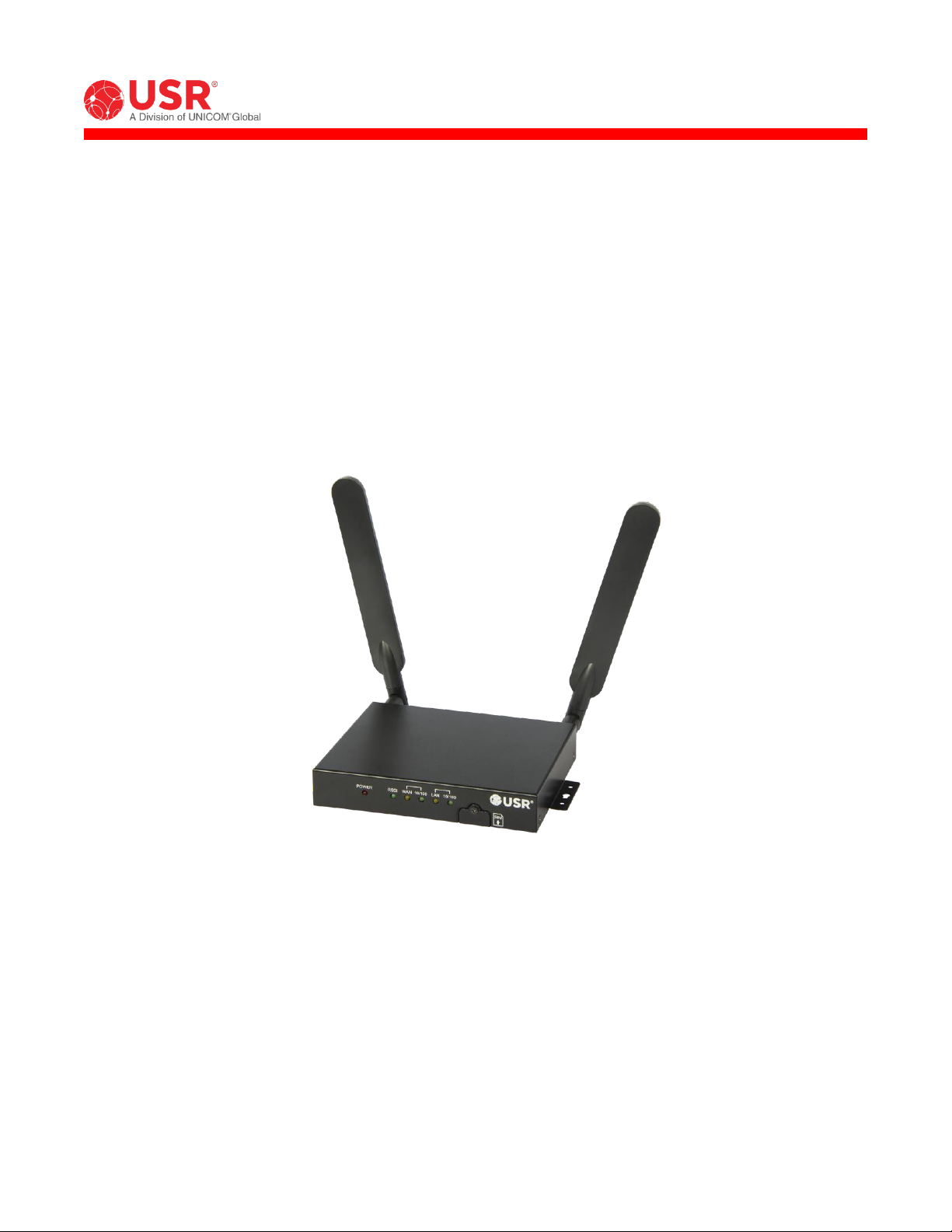
Courier® M2M 4G LTE Cat 1 Cellular Gateway
User Guide
USR3513
USR803513
R24.0806.00
Rev 1.0 10/2018
Page 2

USR3513/USR803513 User Guide
Contents
INTRODUCTION ................................................................................................................ 3
Product Overview ........................................................................................................... 4
Package Contents........................................................................................................... 6
Product Highlights .......................................................................................................... 7
Product Specifications ..................................................................................................... 7
Hardware Features ....................................................................................................... 13
Mounting..................................................................................................................... 17
GETTING STARTED .......................................................................................................... 20
Establishing a Cellular Connection .................................................................................. 20
CONFIGURATION ............................................................................................................. 25
Overview .................................................................................................................... 25
Accessing the Web Interface .......................................................................................... 25
Navigating the Web Interface ........................................................................................ 27
Status Page ................................................................................................................. 29
Network Menu ............................................................................................................. 37
Advanced Setup Menu .................................................................................................. 63
Administrator Menu ...................................................................................................... 84
APPENDIX .................................................................................................................... 102
ASCII Table ............................................................................................................... 102
Creating OpenVPN Certificates & Keys .......................................................................... 103
WARRANTY ................................................................................................................... 107
REGULATORY ................................................................................................................ 111
COPYRIGHT .................................................................................................................. 113
Copyright © 2018 USR, a Division of UNICOM Global
Page 2 of 113
Page 3
USR3513/USR803513 User Guide
INTRODUCTION
Thank you for purchasing the USR Courier M2M 4G LTE Cat 1
Cellular Gateway!
For more than three decades, millions of businesses and
consumers have relied on USR for dependable Internet
access. Today, USR endeavors to continue the longstanding
tradition of supporting successful businesses by providing
equipment for data transfer, remote management,
broadband backup, point-of-sale, and machine-to-machine
functions. USR strives to support the latest technologies through the development of new tools, which are
known for their mobility, convenience, and reliability. USR products are designed for multiple environments,
including data centers, remote networks, embedded solutions, and small-to medium-sized business markets.
This User Guide explains how to set-up and use the Courier M2M 4G LTE Cat 1 Cellular Gateway.
This document pertains to both the USR3513 and the USR803513. In this document, the term “Cellular
Gateway” is used when referring to both versions. The terms USR3513 or USR803513 are used when referring to
a specific version.
Screenshots and graphics shown in this guide may differ slightly from your product due to differences in your
product’s firmware, your web browser, or your computer’s operating system.
The following topics are covered in this chapter:
Product Overview
Package Contents
Product Highlights
Product Specifications
Hardware Features
LED Indicators
Reset Button
Mounting
Copyright © 2018 USR, a Division of UNICOM Global
Page 3 of 113
Page 4
USR3513/USR803513 User Guide
Product Overview
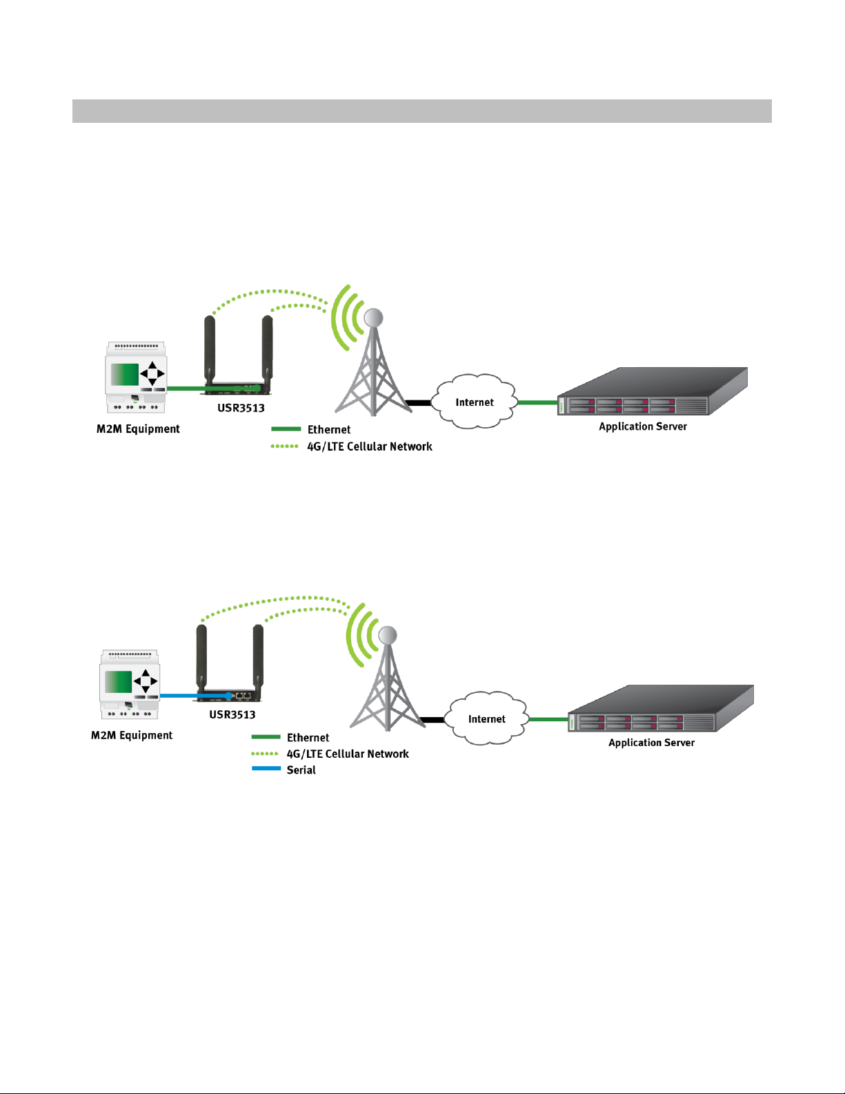
The Courier M2M 4G LTE Cat 1 Cellular Gateway is a wireless device that provides cellular connectivity to the
Internet for machine-to-machine (M2M) and Internet of Things (IoT) applications.
The Cellular Gateway can interface with a wide variety of M2M and IoT equipment via Ethernet or serial port.
For example, the Cellular Gateway can allow remote M2M equipment to wirelessly contact an application server
via the Internet and transmit M2M data, as shown in figure 1.
figure 1
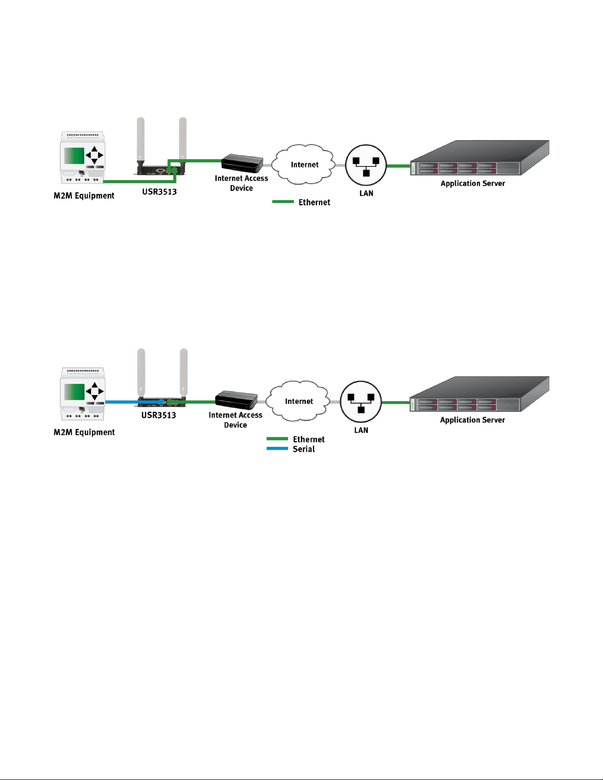
Also, the Cellular Gateway can allow remote serial equipment to wirelessly contact an application server via the
Internet and transmit M2M data, as shown in figure 2.
figure 2
Copyright © 2018 USR, a Division of UNICOM Global
Page 4 of 113
Page 5
USR3513/USR803513 User Guide
In cases where a remote site has wired access to the Internet as shown in figure 3, the Cellular Gateway’s
firewall can protect the remote equipment while allowing a connection to an application server via the Internet.
figure 3
Also in cases where a remote site has wired access to the Internet, the Cellular Gateway can be used as a serialto-Ethernet bridge, allowing remote serial equipment to contact an application server via the Internet to
transmit M2M data, as shown in figure 4.
figure 4
Those are just a few examples of how the versatile USR Courier M2M 4G LTE Cat 1 Cellular Gateway can be part
of a traditional M2M or IoT data communications solution.
Page 5 of 113
Copyright © 2018 USR, a Division of UNICOM Global
Page 6

USR3513/USR803513 User Guide
Package Contents
USR’s Courier M2M 4G LTE Cat 1 Cellular Gateway is shipped with the following items. If any of these items are
missing or damaged, please contact your customer service representative for assistance.
USR3513
1 USR3513 Cellular Gateway
1 Power supply with fixed blades for North America
2 4G/3G/2G omni-directional antennas, 0 dBi, SMA (male)
1 Ethernet cable
1 Quick start guide (printed)
USR803513
1 USR803513 Cellular Gateway
1 Power supply with interchangeable EU and UK blades
2 4G/3G/2G omni-directional antennas, 0 dBi, SMA (male)
1 Ethernet cable
1 Quick start guide (printed)
NOTE: The above items come with the standard Cellular Gateway models, but the package contents may vary
for customized versions.
Copyright © 2018 USR, a Division of UNICOM Global
Page 6 of 113
Page 7

USR3513/USR803513 User Guide
Product Highlights
Single unit supports multiple cellular networks
Configure for your cellular operator in less than a minute (USR3513)
Category 1 speeds on 4G LTE networks, ideal for M2M applications
Fallback to 3G UMTS networks (USR3513) when outside of 4G LTE coverage
Fallback to 2G networks (USR803513) when outside of 4G LTE coverage
Interface to Ethernet or serial equipment
Includes two types of VPN for contacting an M2M server that’s behind a firewall
User-friendly web interface for enabling connectivity, configuring the firewall, setting serial port
parameters, and monitoring operational status
Concealed SIM slot discourages unauthorized removal of SIM
Can be remotely configured from a web browser
Product Specifications
Cellular Interface Standards
USR3513: LTE Cat 1, HSPA
USR803513: LTE Cat 1, GPRS
Band Options
USR3513
LTE Cat 1: 1900/AWS1700/850/700 MHz (B2/B4/B5/B12/B13)
HSPA/UMTS: 1900/850 MHz (B2/B5)
USR803513
LTE Cat 1: 2100/1800/2600/900/800 MHz (B1/B3/B7/B8/B20)
GPRS/GSM: 1800/900 MHz (B3/B8)
Copyright © 2018 USR, a Division of UNICOM Global
Page 7 of 113
Page 8

USR3513/USR803513 User Guide
LTE Cat 1 Data Rate
Downlink: Up to 10 Mbps
Uplink: Up to 5 Mbps
HSPA Data Rate
Downlink: Up to 42 Mbps (category 24)
Uplink: Up to 5.7 Mbps (category 6)
GPRS Data Rate
Downlink: Up to 58 Mbps (class 8)
Uplink: Up to 14 Mbps (class 8)
Downlink: Up to 43 Mbps (class 10)
Uplink: Up to 29 Mbps (class 10)
Cellular Antenna Connectors
1 Main, SMA female, 50 ohm
1 Auxiliary, SMA female, 50 ohm
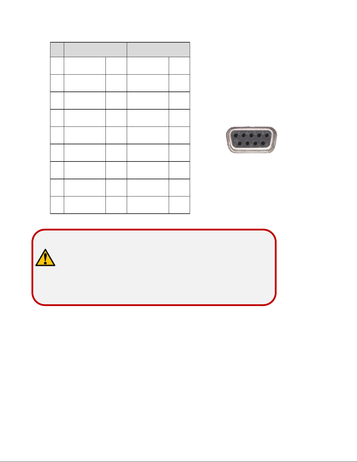
Serial Interface
1 DB9-F connector, DCE, RS-232 or RS-485 signaling
Speeds (bps): 115200, 57600, 38400, 19200, 9600, 4800, 2400, 1200
Data Bits: 6, 7, 8
Parity: None, Odd, Even
Flow Control: None, Hardware
Copyright © 2018 USR, a Division of UNICOM Global
Page 8 of 113
Page 9
USR3513/USR803513 User Guide
Pin
RS-232
RS-485
1 * - - - 2 TXD
O
TXD+
O
3
RXD
I
RXD+
I 4 DCD* O -
-
5
GND
-
GND
- 6 DTR* I -
-
7
CTS I RXD-
I 8 RTS O TXD-
O
9 - - - -
ATTENTION: *This is a non-standard pinout for an RS232 DCE
Applications that expect DCD and/or DSR signals
require a custom-wired cable or adaptor.
1
5
6
9
on a DB9-F connector!
from the DCE to drive DCD and DSR inputs will
LAN Interface
1 RJ45 connector, Ethernet, 10/100 Mbps, auto MDI/MDIX
WAN Interface
1 RJ45 connector, Ethernet, 10/100 Mbps, auto MDI/MDIX
Power Connector
1 Barrel connector, 5.5 mm O.D., 2.1 mm I.D., center positive
Page 9 of 113
Copyright © 2018 USR, a Division of UNICOM Global
Page 10

USR3513/USR803513 User Guide
LED Indicators
6 LEDs: POWER, RSSI, WAN, WAN 10/100, LAN, LAN 10/100
Reset Button
Reboot or Factory default + reboot, recessed
SIM Interface
1 SIM slot, 2FF, 1.8V/3V, USIM/SIM class B and class C
Power Requirements
Input Voltage: 8 to 12.5 VDC
Power Consumption: 3.6W idle (typical), 5.7W full load (typical)
Networking Protocols
ICMP, TCP, UDP and ARP
HTTP, HTTPS
DHCP, Telnet, SSH
IPSEC, OpenVPN
Security
IPsec
Encryption: DES, 3DES, AES192, AES 256
Authentication: MD5, SHA1
Key Group: MODP1024, MODP1536
Connection Type: Site-to-Site
OpenVPN
Interface: TAP, TUN
Protocol: TCP, UDP
Connection Type: Site-to-Site
Firewall
Remote Access
DMZ
Inbound Port Forwarding
Outbound Port Filtering
Outbound Trusted IPs
Copyright © 2018 USR, a Division of UNICOM Global
Page 10 of 113
Page 11

USR3513/USR803513 User Guide
Web Interface
Accessible via web browsers that support HTML5
Physical Characteristics
Housing: Industrial-grade steel
Dimensions: 5.85 x 4.46 x 1.04 in. (14.88 x 11.33 x 2.65 cm)
Weight: 0.95 lb (0.43 kg)
Installation: wall-mount or DIN-rail (DIN adaptor not included)
Environmental
Operating Temperature: -10 to 70° C
Storage Temperature: -40 to 85°C
Ambient Relative Humidity: 5 to 95% (non-condensing)
Regulatory Standards and Certifications
USR3513
EMC: FCC, Industry Canada (IC)
Network: PTCRB (module only)
Carrier approvals: AT&T (module only)
Verizon (module only)
Energy efficiency: DoE level VI
USR803513
Safety & EMC: (see CE Declaration of Conformity)
Network: GCF (module only)
Energy efficiency: ErP level VI
Hazardous Substances: RoHS compliant
Reliability
USR3513 MTBF: 1,110 yrs (module only)
USR803513 MTBF: 1,055 yrs (module only)
Warranty
Warranty Period: Two-year limited manufacturer warranty from date of purchase
Details: See www.usr.com/support/3513
Copyright © 2018 USR, a Division of UNICOM Global
Page 11 of 113
Page 12
USR3513/USR803513 User Guide
ATTENTION: The USR3513 and USR803513 Cellular Gateways use networking
ATTENTION: The USR3513 and the USR803513 are not portable cellular
devices and should be located at least 20 cm away from the
human body.
protocols. To setup and use these devices, familiarity with
networking techniques is required.
Copyright © 2018 USR, a Division of UNICOM Global
Page 12 of 113
Page 13

1 2 3
4 5 6 7 8
9
10
Hardware Features
Front View
1. LEDs
2. SIM slot cover
3. SIM slot cover screw
USR3513/USR803513 User Guide
Rear View
4. Auxiliary antenna connector
5. Recessed reset button
6. Power input
7. Serial port
8. WAN port
9. LAN port
10. Main antenna connector
Copyright © 2018 USR, a Division of UNICOM Global
Page 13 of 113
Page 14
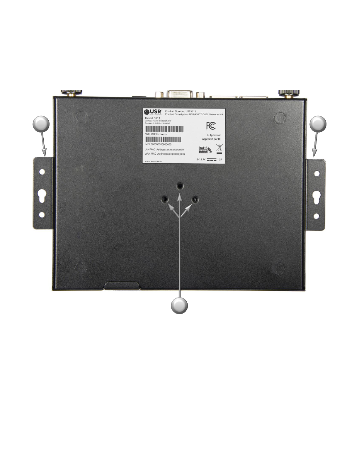
11
11
12
Bottom View
USR3513/USR803513 User Guide
11. Mounting flanges
12. DIN adaptor mounting holes
Page 14 of 113
Copyright © 2018 USR, a Division of UNICOM Global
Page 15
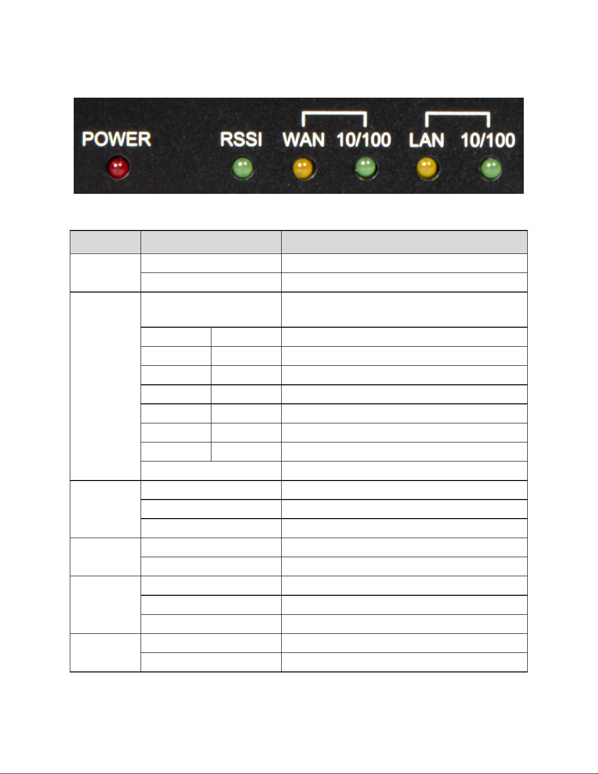
LED
Display
Description
POWER
ON
Indicates that the main power is on
OFF
Indicates that the main power is off
RSSI
Flashing
On (mS)
Off (mS)
Indicates that the cellular radio is active
600
1800
Poor signal strength
800
1200
Weak signal strength
1200
800
Normal signal strength
1600
400
Good signal strength
1800
200
Excellent signal strength
200
1800
No SIM
200
1800
Not registered to a cellular network
OFF
Indicates a cellular radio fault
WAN
ON
Indicates a connection to an active network
Blinking
Indicates data traffic on the network
OFF
Indicates no connection to an active network
WAN 10/100
ON
Indicates a 100BASE-T network
OFF
Indicates a 10BASE-T network
LAN
ON
Indicates a connection to an active network
Blinking
Indicates data traffic on the network
OFF
Indicates no connection to an active network
LAN 10/100
ON
Indicates a 100BASE-T network
OFF
Indicates a 10BASE-T network
LED Indicators
USR3513/USR803513 User Guide
Copyright © 2018 USR, a Division of UNICOM Global
Page 15 of 113
Page 16
USR3513/USR803513 User Guide
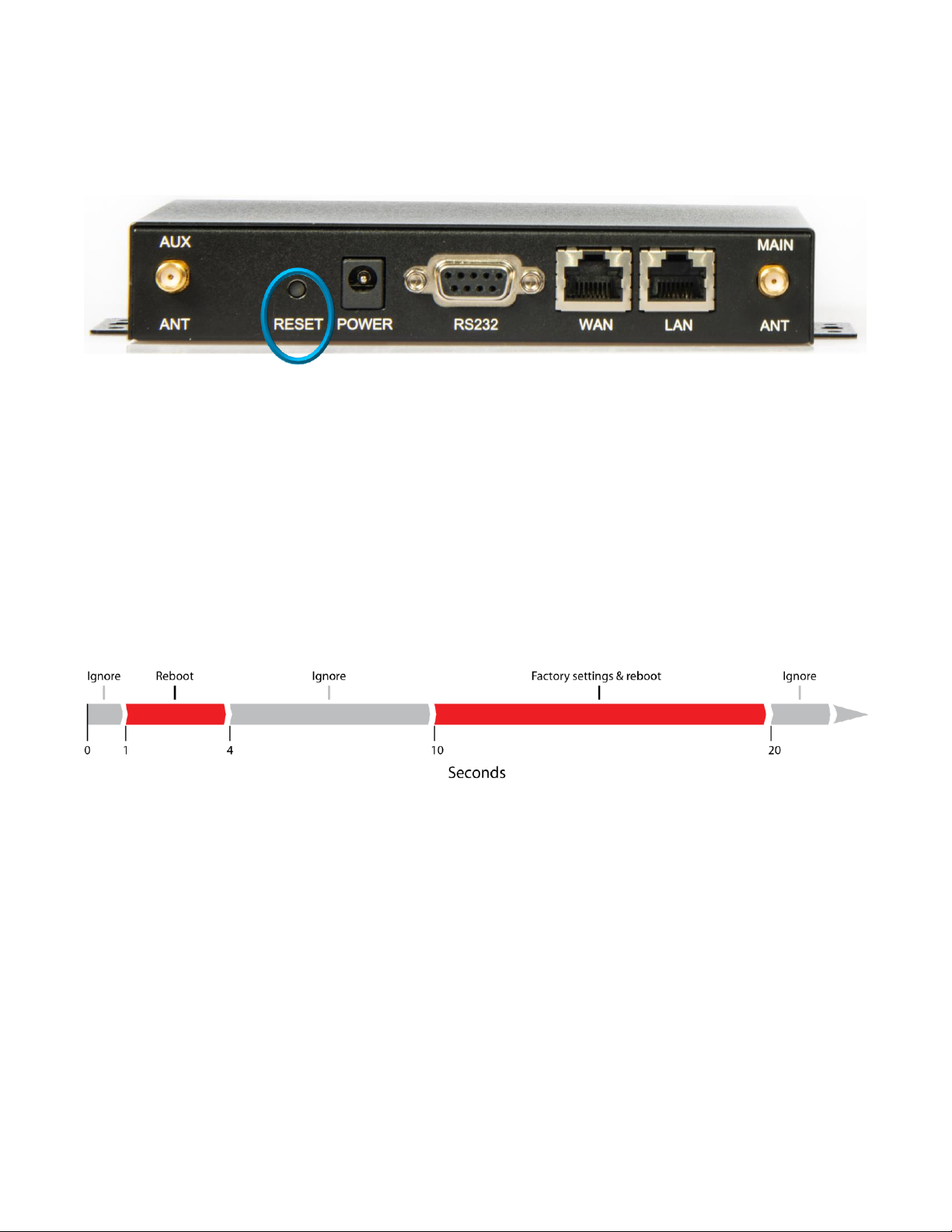
Reset Button
The recessed hardware reset button is located on the unit’s back panel.
Using a pen or small screwdriver, press and hold as follows:
If the reset button is pressed for less than one second it will be ignored.
Hold for one to four seconds to perform a reboot when the button is released.
If the reset button is pressed for more than four seconds up to ten seconds it will be ignored.
Hold for more than ten seconds up to twenty seconds to restore factory settings and reboot when the
button is released.
If the reset button is pressed for more than twenty seconds it will be ignored.
Copyright © 2018 USR, a Division of UNICOM Global
Page 16 of 113
Page 17
USR3513/USR803513 User Guide
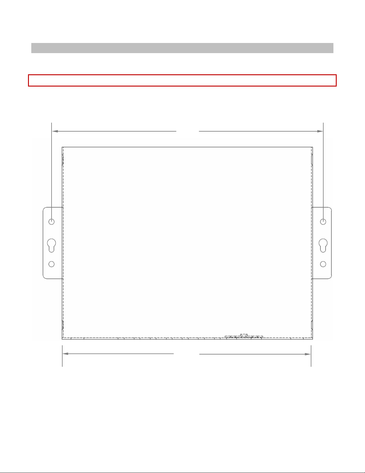
161
148.6
Mounting
The Cellular Gateway provides two flanges for mounting to a wall or any other flat surface.
NOTE: Dimensions are in millimeters.
TOP VIEW
Page 17 of 113
Copyright © 2018 USR, a Division of UNICOM Global
Page 18
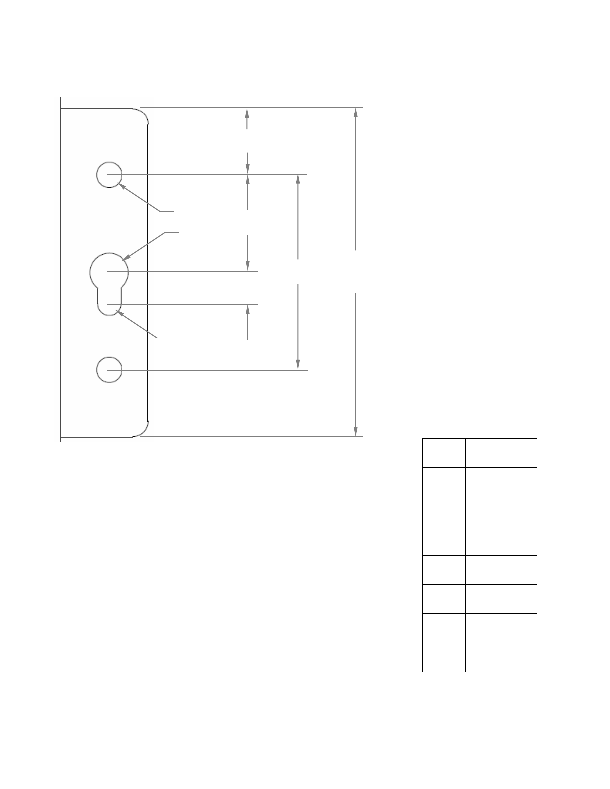
a
b
c
d
e
Ø1
Ø2
Ø3
a
42
b
8.5 c 12 d 4.0 e 25
Ø1
3.2
Ø2
5.0
Ø3
3.0
Mounting Flange Detail
USR3513/USR803513 User Guide
Copyright © 2018 USR, a Division of UNICOM Global
Page 18 of 113
Page 19
USR3513/USR803513 User Guide
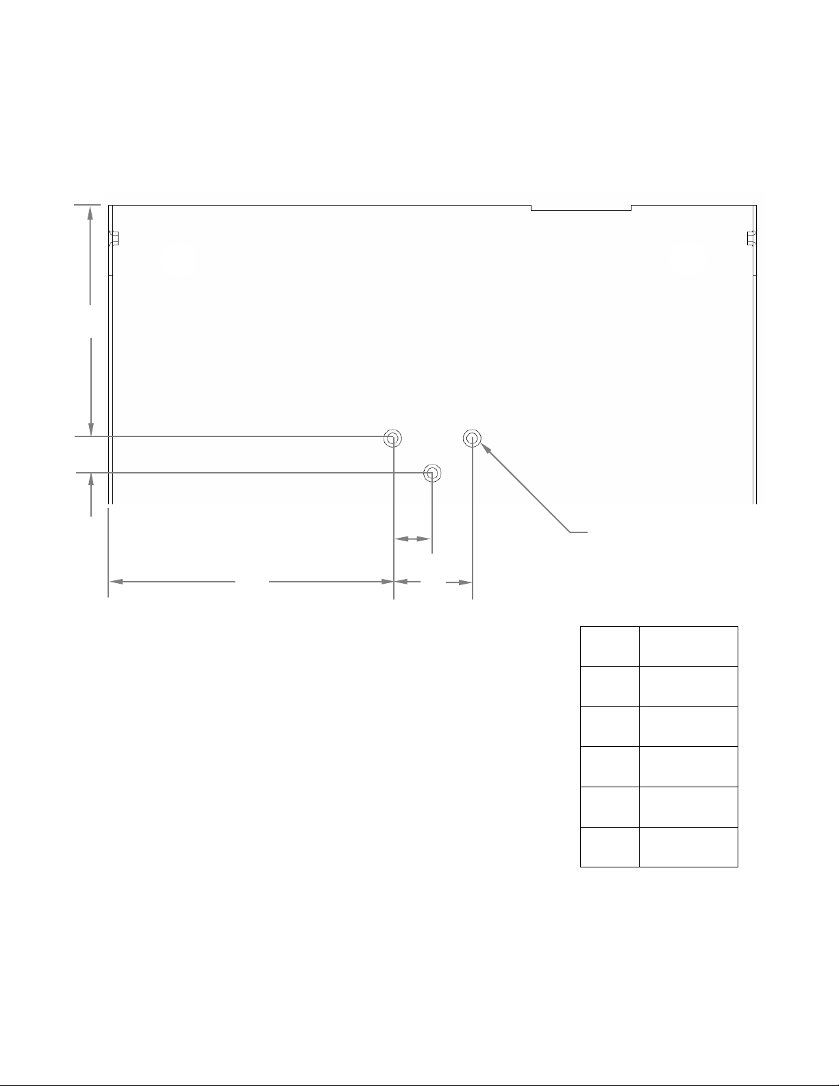
a
52.5
b
8.0 c 9.0
d
18
e
64.4
Ø1
M3-0.5
a
b
c
e
d
Ø1
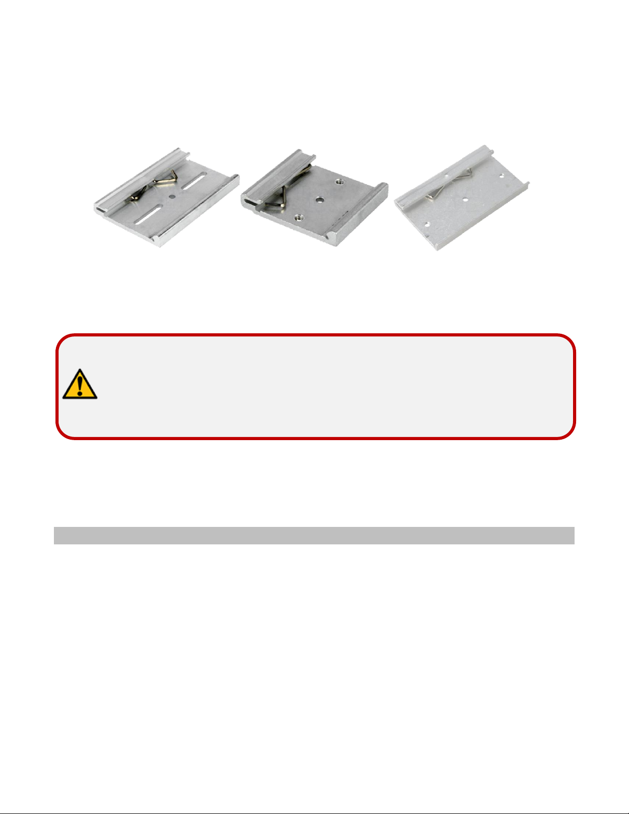
DIN Rail Mounting
The Cellular Gateway provides mounting holes for a DIN rail adaptor.
BOTTOM VIEW
Copyright © 2018 USR, a Division of UNICOM Global
Page 19 of 113
Page 20
USR3513/USR803513 User Guide
when fully tightened! Screws that extend further than 3 mm may
DIN rail adaptors with various mounting hole patterns are commercially available online and from electronics
distributors.
Examples:
Choose an adaptor with slots or holes whose diameter and positions line-up with one, two, or three of the
Cellular Gateway’s mounting holes.
ATTENTION: When fastening a DIN rail adaptor to the Cellular Gateway, use
screws that will not extend more than 3 mm into the housing
damage the Cellular Gateway!
GETTING STARTED
Follow the steps in this chapter to setup a connection from the Cellular Gateway to a cellular data network.
Establishing a Cellular Connection
1. Attach the included antennas to the antenna connectors on the back of the device.
2. Make sure that a service plan is associated with a SIM card.
Copyright © 2018 USR, a Division of UNICOM Global
Page 20 of 113
Page 21
3
7
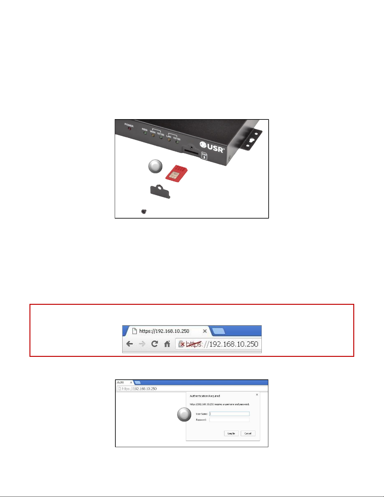
3. To install the SIM:
• Remove the Phillips screw from the cover plate on the front of the unit and remove the plate.
• Insert the SIM into the SIM slot, oriented as shown in the picture below. The SIM must click into
place.
• Replace the cover plate and the Phillips screw.
USR3513/USR803513 User Guide
4. Power-up the Cellular Gateway by plugging the provided power supply into the power connector on the
back of the Cellular Gateway, and into a power source. Allow one or two minutes for the Cellular
Gateway to fully power up.
5. Connect an Ethernet cable to the Cellular Gateway’s LAN port on one end and a computer on the other
end.
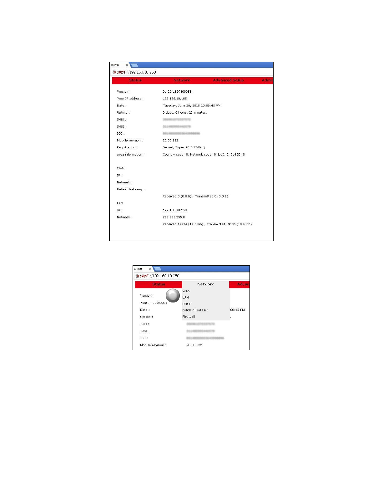
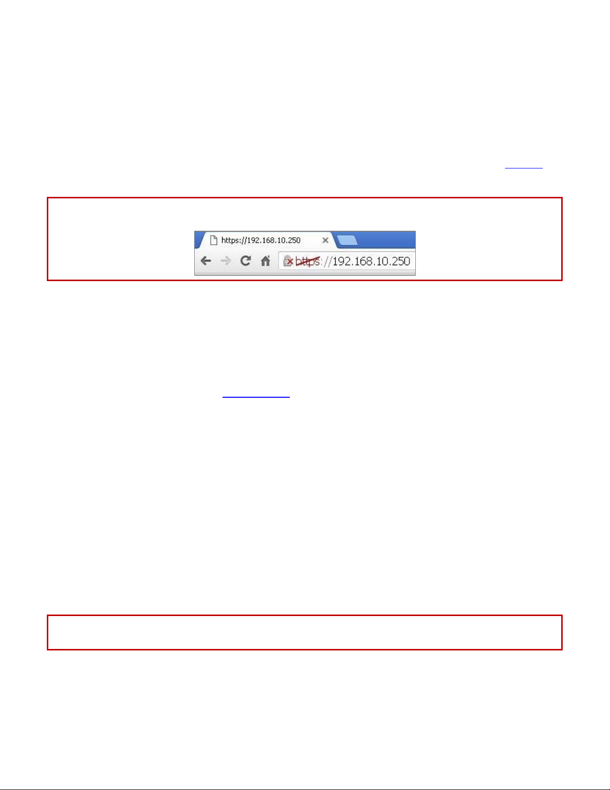
6. Open a web browser on the computer and enter the address 192.168.10.250 into the address bar.
NOTE: Some browsers may display a security warning. Accept the warning to open an unencrypted https
session.
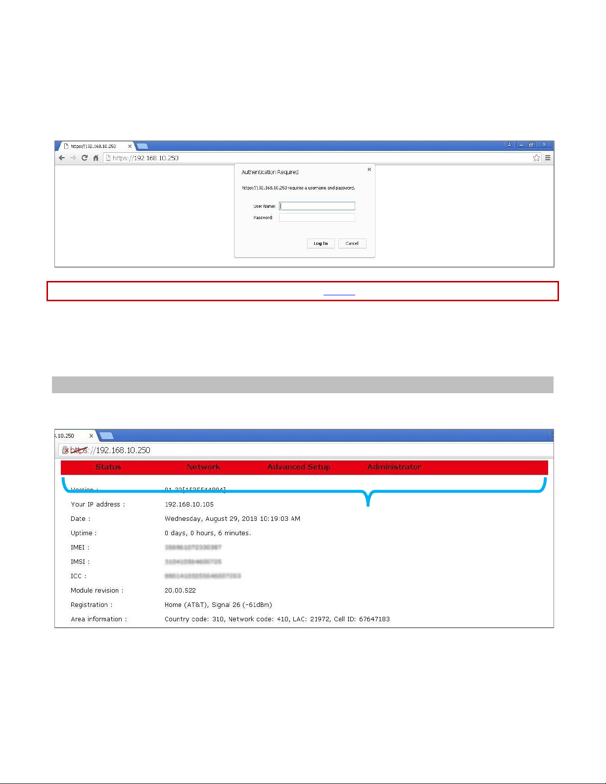
7. Enter the default User Name (admin) and Password (password).
Page 21 of 113
Copyright © 2018 USR, a Division of UNICOM Global
Page 22
USR3513/USR803513 User Guide
8
After a successful login, the Status page will appear.
8. Click Network on the red menu bar and select WAN.
Copyright © 2018 USR, a Division of UNICOM Global
Page 22 of 113
Page 23
USR3513/USR803513 User Guide
9
10
11
12
13
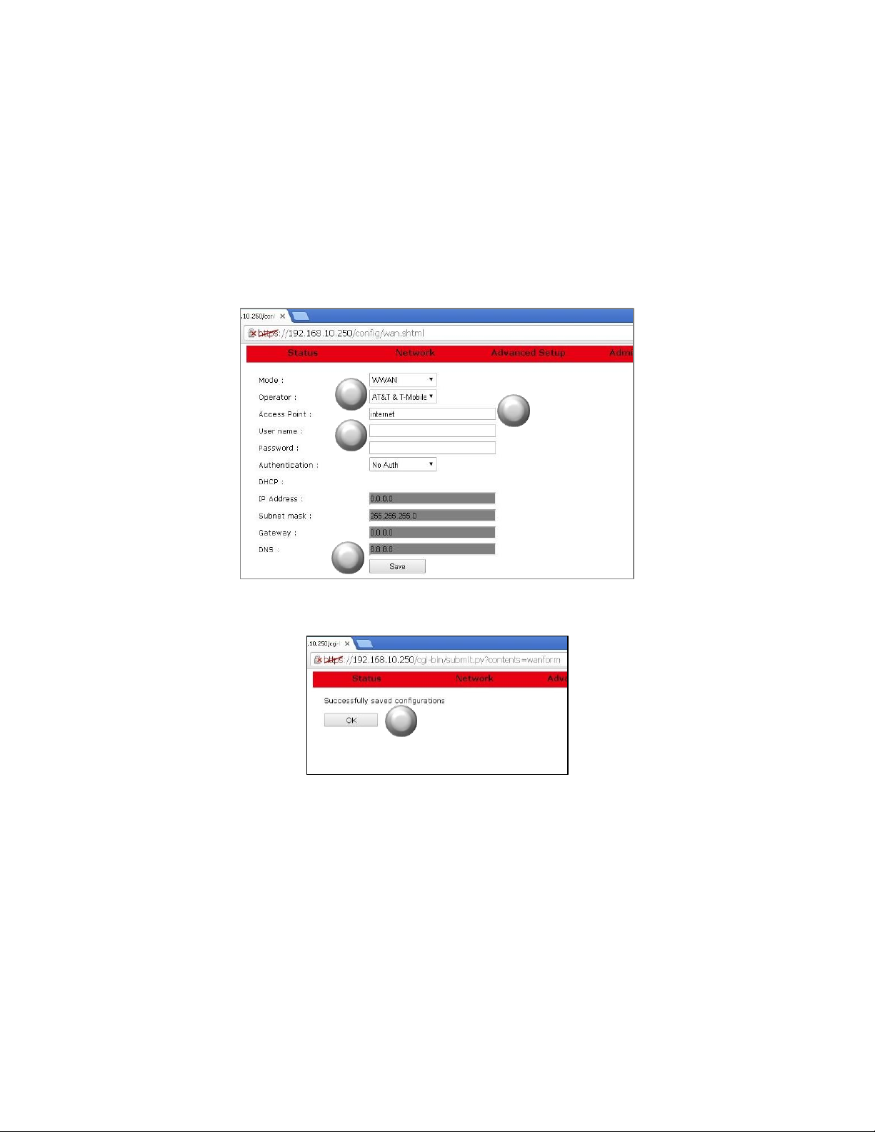
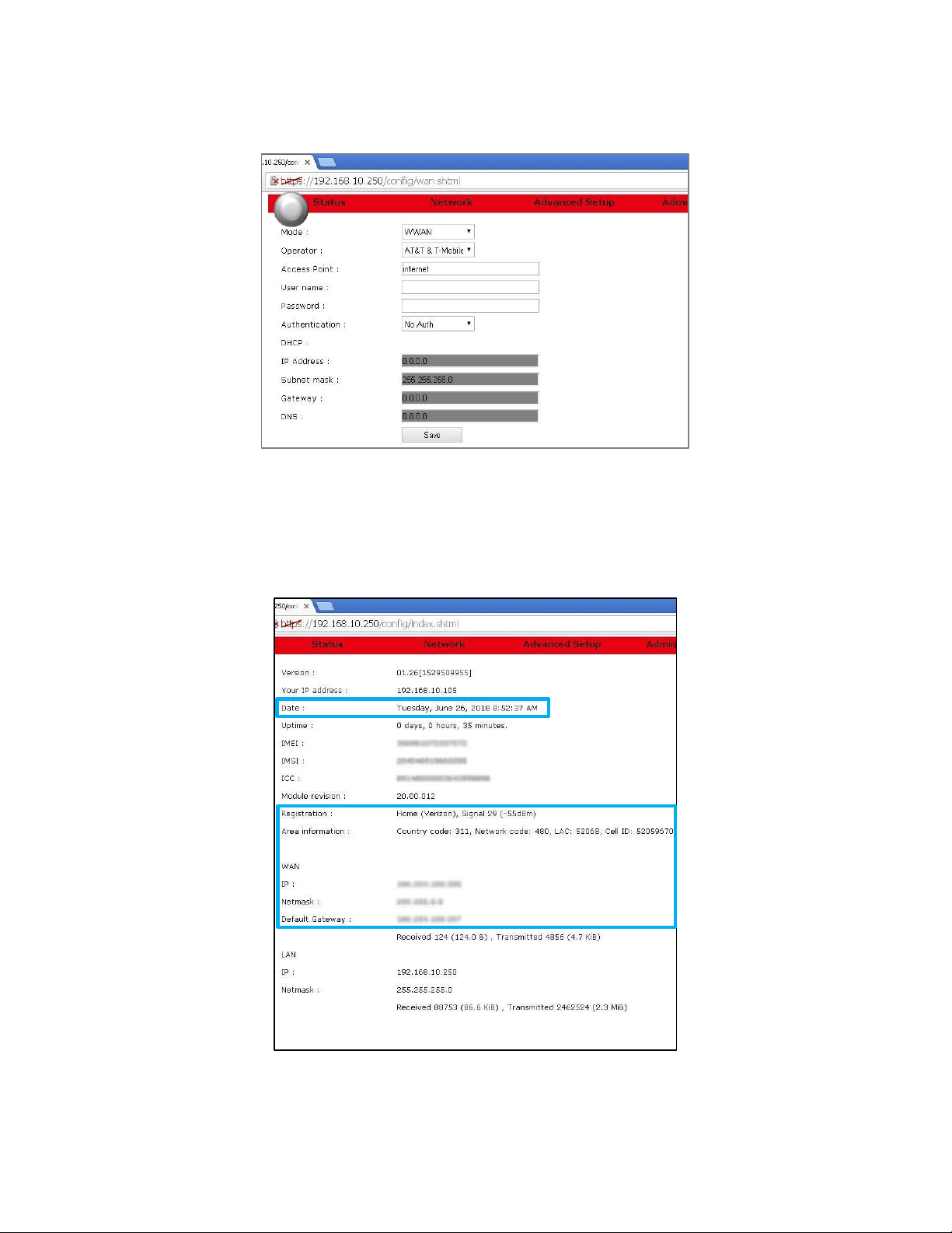
9. For the USR3513: On the WAN page, with Mode set to WWAN, select the radio firmware for the cellular
operator that you are using.
For the USR803513: Skip to the next step.
10. Enter the APN (assigned by the cellular service provider) into the Access Point field.
11. Enter a User name and Password if supplied by the cellular service provider.
12. Click the Save button. A confirmation page will appear.
13. Click the OK button. The WAN page will reappear.
Copyright © 2018 USR, a Division of UNICOM Global
Page 23 of 113
Page 24
USR3513/USR803513 User Guide
14
14. Click Status on the menu bar of the WAN page to confirm the cellular connection on the Status page.
A connection to the network will be setup automatically. In a few seconds when the connection is
complete, entries will appear in the Registration, Area Information, WAN IP, WAN Netmask, and WAN
Default Gateway fields.
The Cellular Gateway’s date and time will automatically synchronize to the network clock.
Now you can proceed with configuring the Cellular Gateway for the target application.
Page 24 of 113
Copyright © 2018 USR, a Division of UNICOM Global
Page 25

USR3513/USR803513 User Guide
CONFIGURATION
The following topics are covered in this chapter:
Overview
Accessing the Web Interface
Local Access
Remote Access
Logging In
Navigating the Web Interface
Status Page
Network Menu
WAN Page
LAN Page
DHCP page
DHCP Client List
Firewall Page
Overview
Advanced Setup Menu
Serial Page
IPSec Page
OpenVPN Page
Administrator Menu
Logs Page
Time Page
F/W Upgrade Page
Password Page
Factory Reset Page
Save/Restore Settings page
Log out
Reboot Page
The USR Courier M2M 4G LTE Cat 1 Cellular Gateway provides an embedded web interface for a convenient and
intuitive way to configure the Cellular Gateway and monitor its status.
In this chapter, default settings are identified by a Bold Italic font.
Accessing the Web Interface
The web interface is accessed locally via a web browser running on a computer connected to the gateway, or
remotely via a web browser running on a computer or mobile device. The recommended web browsers are:
IE 10 or newer
Firefox (all)
Opera 12 or newer
Safari 6 or newer
Chrome (all)
Copyright © 2018 USR, a Division of UNICOM Global
Page 25 of 113
Page 26
USR3513/USR803513 User Guide
Local Access
Local access to the web interface is made by connecting an Ethernet cable from a computer to the LAN port of
the Cellular Gateway.
To access the web interface, open a web browser on the computer and enter the IP address of the embedded
web interface into the browser’s address bar. The default IP address is 192.168.10.250, which can be changed
later if desired.
NOTE: Some browsers may display a security warning. Accept the warning to open an unencrypted https
session.
Remote Access
Remote access to the web interface can be made from a computer or mobile device* that has a connection to
the Internet (or to a private network), under the following conditions:
The Cellular Gateway has Remote Access enabled
The Cellular Gateway has a cellular or a wired connection to the Internet (or to a private network)
The Cellular Gateway is at an IP address that is known and is routable from the computer or mobile
device
*The Cellular Gateway’s web interface is not optimized for viewing on mobile devices.
To access the web interface:
1. Open a web browser on the computer or mobile device.
2. Enter the https:// prefix, the IP address of the SIM, a colon (:), and the Remote Access port number
into the address bar.
Example: https://10.24.85.5:1800
3. Press/touch Enter
NOTE: Some browsers may display a security warning. Accept the warning to open an unencrypted https
session.
Copyright © 2018 USR, a Division of UNICOM Global
Page 26 of 113
Page 27
USR3513/USR803513 User Guide
Menu Bar
Logging In
For either local access or remote access, a Login box will appear in the browser. Enter the default User Name
(admin) and Password (password) and click the Log In button. The User Name and Password are case-sensitive.
NOTE: To prevent unauthorized access to the web interface, change the User Name and Password.
As a security measure, the web interface will automatically log out if it detects no activity for ten minutes. If the
timeout expires, log back in to continue using the web interface.
Navigating the Web Interface
A Menu Bar is displayed at the top of the web interface. It allows navigation to each page of the web interface.
Copyright © 2018 USR, a Division of UNICOM Global
Page 27 of 113
Page 28

USR3513/USR803513 User Guide
Click on an item in the Menu Bar to navigate to a page or to see a drop-down menu of more pages.
The items that are available in the Menu Bar are:
Status Page
Network Menu
• WAN Page
• LAN Page
• DHCP Page
• DHCP Client List
• Firewall Page
Advanced Setup Menu
• Serial Page
• IPSec Page
• OpenVPN Page
Administrator Menu
• Logs Page
• Time Page
• F/W Upgrade Page
• Password Page
• Factory Reset Page
• Save/Restore Settings Page
• Log out
• Reboot Page
Copyright © 2018 USR, a Division of UNICOM Global
Page 28 of 113
Page 29
USR3513/USR803513 User Guide
Status Page
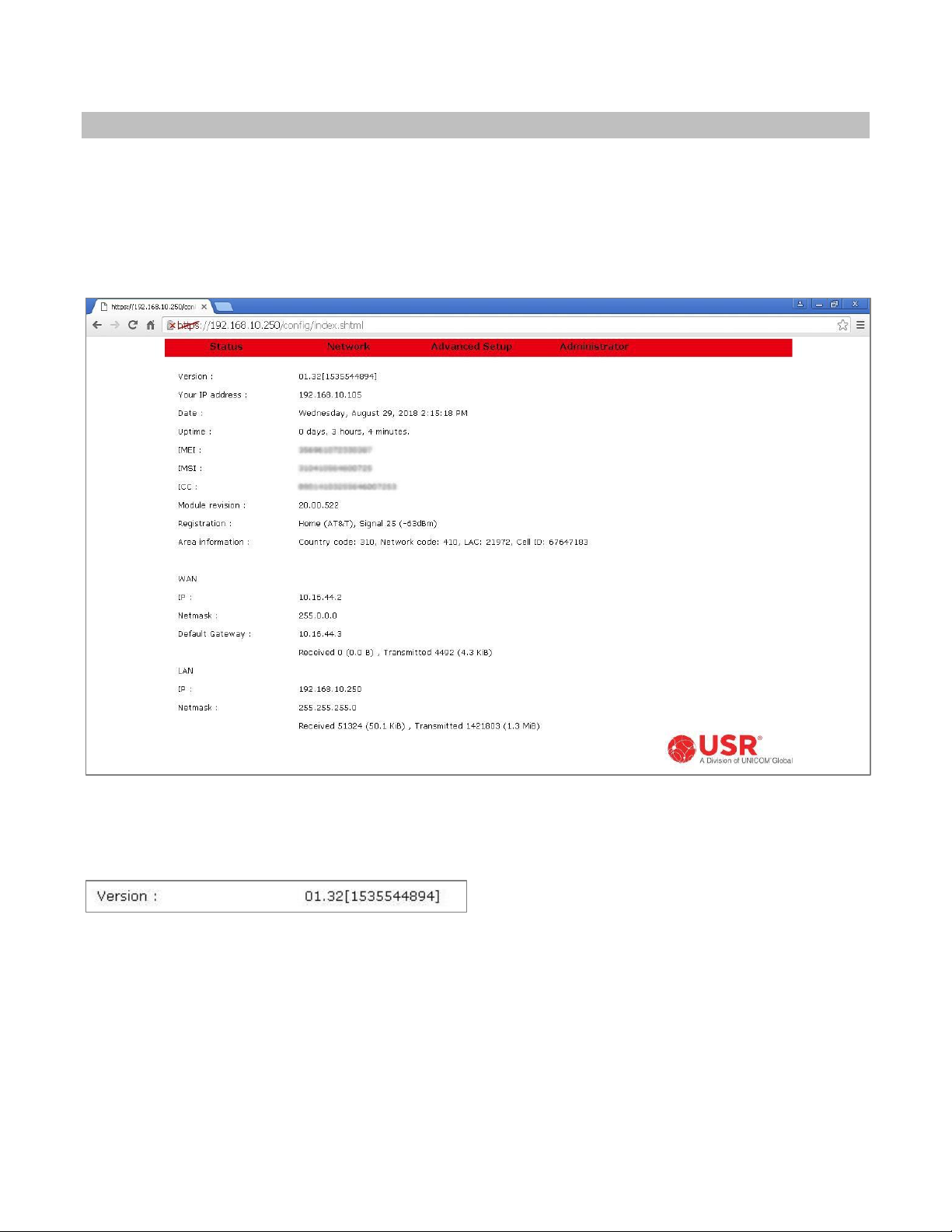
Choose Status in the menu bar to display the Status Page.
The Status Page is the web interface’s home page. It displays important information about the operational
status of the Cellular Gateway.
Each item is described in the following section.
Version
Displays the version number of the Cellular Gateway’s firmware, and a firmware build identifier.
Page 29 of 113
Copyright © 2018 USR, a Division of UNICOM Global
Page 30
USR3513/USR803513 User Guide
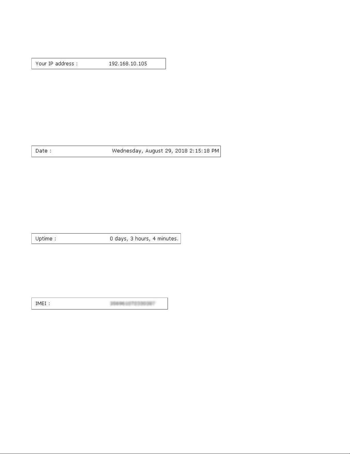
Your IP Address
During a local access session, this displays the IP address of the computer connected to the Cellular Gateway.
During a remote access session, this displays the IP address of the computer or mobile device connected
remotely to the Cellular Gateway.
Date
When the Cellular Gateway has a cellular connection or has a wired connection to a network that has an NTP
server, the Cellular Gateway’s date and time will automatically synchronize to the network.
When no NTP server is found, a default date and time will display.
Uptime
Displays the time duration since the last power-up or reboot.
IMEI
Displays the International Mobile Equipment Identity number, which is a unique identifier of the Cellular
Gateway’s embedded radio module.
Copyright © 2018 USR, a Division of UNICOM Global
Page 30 of 113
Page 31

USR3513/USR803513 User Guide
IMSI
Displays the International Mobile Subscriber Identity number, which is a unique identifier of the cellular
subscriber associated with the SIM installed in the Cellular Gateway’s SIM slot.
ICC
Displays the Integrated Circuit Card Identifier (ICCID) number, which is a unique identifier printed on the SIM
installed in the Cellular Gateway’s SIM slot.
Module Revision
Displays the embedded radio module’s firmware version number.
Copyright © 2018 USR, a Division of UNICOM Global
Page 31 of 113
Page 32

USR3513/USR803513 User Guide
Registration
Displays the status of the Cellular Gateway’s connection to a cell tower.
Registration status
Home (Operator): Displayed when the Cellular Gateway is connected to a cell tower that is operated by
a carrier with which the SIM has an active subscription. Operator displays the name of the cell tower
operator.
Roaming (Operator): Displayed when the Cellular Gateway has a roaming connected to a cell tower that
is not operated by a carrier with which the SIM has an active subscription. Operator displays the name
of the cell tower operator.
Not registered, ME is not currently searching a new operator to register: Displayed when the Cellular
Gateway is not currently searching for a connection to a cell tower.
Not registered, but ME is currently searching a new operator to register: Displayed when the Cellular
Gateway is actively searching for a connection to a cell tower.
Denied: Displayed when a cell tower has refused a connection request from the Cellular Gateway.
Unknown: Displayed when none of the above conditions apply.
Signal quality and strength
When the Cellular Gateway is registered with a cell tower, the signal quality and signal strength are displayed as
two numbers.
The first number that follows the (Operator) is a signal quality measurement that ranges from 31 (best) to 0
(worst). When no connection is found, the number 99 is displayed.
The number in parenthesis is the signal strength displayed in dBm, which ranges from -51 dBm (strongest) to 113 dBm (weakest). When the Cellular Gateway is not registered or couldn’t find a cell tower, -125 dBm is
reported.
Good: -51 to -79 dBm
Fair: -80 to -103 dBm
Bad: -104 to -113 dBm, -125 dBm
Copyright © 2018 USR, a Division of UNICOM Global
Page 32 of 113
Page 33

USR3513/USR803513 User Guide
Area Information
Displays information about the cell tower to which the Cellular Gateway has registered.
Country code: The country code number reported by the cell tower.
Network code: The cellular operator code number reported by the cell tower.
LAC: The location area code number reported by the cell tower.
Cell ID: The cell ID number reported by the cell tower.
Copyright © 2018 USR, a Division of UNICOM Global
Page 33 of 113
Page 34

USR3513/USR803513 User Guide
Mode
Setting
DHCP
Setting
IP
Netmask
Default Gateway
WWAN
n/a
Assigned by the
cellular network
Assigned by the
cellular network
Assigned by the
cellular network
WAN
Enable
Assigned by the
local-area network
Assigned by the
local-area network
Assigned by the
local-area network
Disable
Assigned manually in
the WAN page
Assigned manually in
the WAN page
Assigned manually in
the WAN page
WAN
This section displays information about the WWAN (cellular) or WAN (Ethernet) connection.
The network information displayed in this section depends on the Mode setting in the WAN page and the DCHP
setting in the WAN page. The following table shows how the network information is effected by the Mode and
DHCP settings.
Received & Transmitted
Displays the cumulative number of bytes received and transmitted over either type of WAN connection since the
last power-up or reboot.
Copyright © 2018 USR, a Division of UNICOM Global
Page 34 of 113
Page 35

USR3513/USR803513 User Guide
VPN
The Cellular Gateway provides two types of VPN on its WAN connection: IPSec and OpenVPN.
When the Cellular Gateway has IPSec enabled, this section appears and displays information about the VPN
connection.
IPSec Status
Displays Idle when IPSec is enabled but a tunnel is not established.
Displays Connected when an IPSec tunnel is established.
Remote IP
Reports the IP address of the IPSec endpoint at the far end of the VPN tunnel.
Remote Client IP is reported when the other VPN endpoint is an IPSec client.
Remote Gateway IP is reported when the other VPN endpoint is an IPSec gateway.
When the Cellular Gateway has OpenVPN enabled, this section appears and displays information about the VPN
connection.
OpenVPN Status
Displays Idle when an OpenVPN client is enabled but a tunnel is not established.
Displays Listening when an OpenVPN server is enabled but a tunnel is not established.
Displays Connected when an OpenVPN tunnel is established.
IP
Reports the IP address of the OpenVPN endpoint at the far end of the VPN tunnel.
Copyright © 2018 USR, a Division of UNICOM Global
Page 35 of 113
Page 36

USR3513/USR803513 User Guide
LAN
This section displays information about the Cellular Gateway’s LAN port.
IP
Displays the current IP address of the Cellular Gateway’s LAN port. The embedded web interface is accessed at
this IP address. The default IP address is 192.168.10.250, which can be changed on the LAN page.
Netmask
Displays the current IP netmask of the Cellular Gateway’s LAN port. The default netmask is 255.255.255.0, which
can be changed on the LAN page.
Received & Transmitted
Displays the cumulative number of bytes received and transmitted over the LAN connection since the last
power-up or reboot.
Copyright © 2018 USR, a Division of UNICOM Global
Page 36 of 113
Page 37

USR3513/USR803513 User Guide
ATTENTION: The USR3513 and USR803513 Cellular Gateways use networking
Network Menu
Choose Network in the menu bar to display the Network Menu.
Select WAN from the Network Menu to display the WAN Page.
Select LAN from the Network Menu to display the LAN Page.
Select DHCP from the Network Menu to display the DHCP Page.
Select DHCP Client List from the Network Menu to display the DHCP Client List.
Select Firewall from the Network Menu to display the Firewall Page.
Each is described in the following section.
protocols. To setup and use these devices, familiarity with
networking techniques is required.
Copyright © 2018 USR, a Division of UNICOM Global
Page 37 of 113
Page 38

USR3513/USR803513 User Guide
NOTE: For access to a cellular data network, contact a cellular network operator
WAN Page
This page configures the Cellular Gateway to connect either to a local-area network via the gateway’s WAN port,
or to a cellular data network.
Changes to settings on this page don’t take effect until saved!
for a subscription to a cellular data plan.
Page 38 of 113
Copyright © 2018 USR, a Division of UNICOM Global
Page 39

USR3513/USR803513 User Guide
connection will not complete until a valid User name and/or Password is
Mode
This setting chooses a WWAN (cellular) or WAN (Ethernet) connection.
WWAN: The Cellular Gateway’s embedded radio module will try to connect to a cellular data network.
WAN: The Cellular Gateway’s WAN port will try to connect to a local-area network.
Operator (USR3513 only)
This setting configures the embedded radio module firmware for a specific cellular network.
Verizon: The embedded radio module will run firmware that is approved for the Verizon 4G LTE cellular
network.
AT&T & T-Mobile: The embedded radio module will run firmware that is approved for the AT&T 4G LTE cellular
network and also works on the T-Mobile 4G LTE cellular network.
LTE Generic: The embedded radio module will run firmware that works on most other 4G LTE cellular networks.
Access Point
The cellular network operator usually will provide an APN (Access Point Name) to the subscriber. Enter the APN
into this field to connect to the Internet via the cellular data network.
NOTE: If the cellular network also required a User name and/or Password, the
entered.
Copyright © 2018 USR, a Division of UNICOM Global
Page 39 of 113
Page 40

USR3513/USR803513 User Guide
User name
The cellular network operator may provide an assigned User name, or may provide instructions for choosing a
User name. Enter the User name into this field. Leave it blank if a User name is not required by the cellular
network.
Password
The cellular network operator may provide an assigned Password, or may provide instructions for choosing a
Password. Enter the Password into this field. Leave it blank if a Password is not required by the cellular network.
Authentication
No Auth: Use this setting when the WAN connection is not authenticating Point-to-Point Protocol (PPP).
PAP: Password Authentication Protocol is used by Point-to-Point Protocol (PPP) to authenticate clients. Use this
setting when connecting to a PPP server that requires PAP authentication.
CHAP: Challenge Handshake Authentication Protocol is a secure method to authenticate clients used by Pointto-Point Protocol (PPP). Use this setting when connecting to a PPP server that requires CHAP authentication.
Copyright © 2018 USR, a Division of UNICOM Global
Page 40 of 113
Page 41

USR3513/USR803513 User Guide
NOTE: Consult with the local-area network’s administrator before attaching any
DHCP
The Cellular Gateway’s DHCP client lets a network automatically assign an IP address to the gateway’s WWAN or
WAN connection.
When Mode is set to WWAN, the DHCP client is enabled and no selection is available.
When Mode is set to WAN, the DHCP client is disabled by default and a DHCP pull-down menu becomes
available.
Enable: Use this setting so the Cellular Gateway’s WAN port can automatically get an IP address from a DHCP
server on the local-area network.
Disable: Use this setting when the Cellular Gateway’s WAN port must have a manually-assigned static IP address
on the local-area network.
device that has a static IP address to a network.
Copyright © 2018 USR, a Division of UNICOM Global
Page 41 of 113
Page 42

USR3513/USR803513 User Guide
IP Address, Subnet mask, Gateway, DNS
The contents of these fields depends on the Mode setting and the DCHP setting.
When Mode is set to WWAN, these fields are undefined. Addresses are assigned by the cellular
network.
When Mode is set to WAN and DHCP is set to Enable, these fields are undefined. Addresses are assigned
by the local-area network.
When Mode is set to WAN and DHCP is set to Disable, enter a network IP Address, Subnet mask,
Gateway address, and DNS address into these fields.
Save button
Changes made on this page do not take effect until saved. Click the Save button to make changes effective. To
discard all changes made on the page, navigate to another page or log out of the web interface.
Copyright © 2018 USR, a Division of UNICOM Global
Page 42 of 113
Page 43

USR3513/USR803513 User Guide
LAN Page
This page configures the IP address and subnet mask of Cellular Gateway’s LAN port.
Changes to settings on this page don’t take effect until saved!
Copyright © 2018 USR, a Division of UNICOM Global
Page 43 of 113
Page 44

USR3513/USR803513 User Guide
Host IDs must not match,
DHCP range
Prefixes must match
192.168.10.250
192.168.10.87
192.168.10.235
192.168.10.222
IP addresses
USR3513
LAN port
DHCP range
100 - 119
IP Address
The Cellular Gateway’s LAN IP address is static, and the default is 192.168.10.250.
To change the IP address of the Cellular Gateway’s LAN port, enter the new IP address into this field and click
the Save button.
When choosing a new LAN address, basic network principles must be followed. For example when three nodes
have static IP addresses and the Cellular Gateway’s DHCP server is enabled:
and must stay outside
Subnet mask
The default LAN subnet mask is 255.255.255.0.
To change the subnet mask of the Cellular Gateway’s LAN port, enter the new subnet mask into this field and
click the Save button.
Copyright © 2018 USR, a Division of UNICOM Global
Page 44 of 113
Page 45

USR3513/USR803513 User Guide
Save button
Changes made on this page do not take effect until saved. Click the Save button to make changes effective. To
discard all changes made on the page, navigate to another page or log out of the web interface.
DHCP page
This page enables/disables and configures the Cellular Gateway’s DHCP server.
Changes to settings on this page don’t take effect until saved!
Copyright © 2018 USR, a Division of UNICOM Global
Page 45 of 113
Page 46

USR3513/USR803513 User Guide
Host IDs must not match,
DHCP range
Prefixes must match
192.168.10.250
192.168.10.87
192.168.10.235
192.168.10.222
IP addresses
USR3513
LAN port
DHCP range
100 - 119
Activate
Enable: This setting enables the Cellular Gateway’s DHCP server. Use this setting when any node attached to the
Cellular Gateway’s LAN port will request a DHCP IP address.
For example, when using a computer to access the Cellular Gateway’s web interface, the computer normally will
request an IP address and the Cellular Gateway’s DHCP server will assign an IP address to the computer.
Disable: This setting disables the Cellular Gateway’s DHCP server. Use this setting when all nodes attached to
the Cellular Gateway’s LAN port have a manually-assigned static IP address.
NOTE: When all nodes have a static IP address, the DHCP server can remain enabled, provided that all of the
static IP addresses are outside the DHCP range. That way, a computer can easily join the network to
access the Cellular Gateway’s web interface.
When choosing static IP addresses, basic network principles must be followed. For example when three nodes
have static IP addresses and the Cellular Gateway’s DHCP server is enabled:
and must stay outside
Offset
This entry sets the lowest Host ID number that the Cellular Gateway’s DHCP server can assign. The allowed
range is 1 - 254. The default value is 100.
Copyright © 2018 USR, a Division of UNICOM Global
Page 46 of 113
Page 47

USR3513/USR803513 User Guide
Range
This entry sets the number of sequential Host ID numbers that the Cellular Gateway’s DHCP server can assign.
The allowed range is 1 - 254. The default value is 20.
The highest Host ID number that the DHCP server can assign is (Offset + Range - 1).
DNS
When any node connected to the Cellular Gateway’s LAN port tries to connect to a URL (instead of an IP
address), the Cellular Gateway will try to resolve the URL into an IP address by consulting a DNS server.
The first DNS entry contains the IP address of the primary DNS server.
In an M2M system, using a URL to contact a host may be handy when the host has a dynamic IP address and
reports its current IP address to a DNS server. So if the application will be using URLs, enter the IP address of the
host’s primary DNS server into this field.
DNS
This entry contains the IP address of an alternate DNS server.
If the application will be using URLs, enter the IP address of the host’s alternate DNS server into this field.
Copyright © 2018 USR, a Division of UNICOM Global
Page 47 of 113
Page 48

USR3513/USR803513 User Guide
Lease Time
When the Cellular Gateway’s DHCP server assigns an IP address to a DHCP client attached to the LAN port, the
DHCP protocol also assigns a lease time to that client. When the lease expires, the DHCP client is required to
send another DHCP request.
The default value is 3600 seconds. The allowed range is 60 to 3880000 seconds.
Save button
Changes made on this page do not take effect until saved. Click the Save button to make changes effective. To
discard all changes made on the page, navigate to another page or log out of the web interface.
Copyright © 2018 USR, a Division of UNICOM Global
Page 48 of 113
Page 49

USR3513/USR803513 User Guide
DHCP Client List
When the Cellular Gateway’s DHCP server has assigned IP addresses to DHCP clients, this page displays
information about the DHCP clients and the DHCP leases.
Each row on this page displays information about one DHCP client.
Copyright © 2018 USR, a Division of UNICOM Global
Page 49 of 113
Page 50

USR3513/USR803513 User Guide
Firewall Page
This page configures the Cellular Gateway’s firewall.
Changes to settings on this page don’t take effect until saved!
Copyright © 2018 USR, a Division of UNICOM Global
Page 50 of 113
Page 51

USR3513/USR803513 User Guide
computer attached to the LAN port during gateway set-up may use
the cellular connection for all of its Internet access activities. Data
Default policies
The default policies control two data paths thru the gateway:
Connections from the Cellular Gateway’s LAN & serial ports to the WAN (cellular or Ethernet).
Connections from the WAN (cellular or Ethernet) to the Cellular Gateway’s LAN & serial ports.
LAN -> WAN
Accept: Connections from the LAN to the WAN are allowed. Use this setting when nodes attached to the Cellular
Gateway’s LAN port need to initiate a connection to an IP address on the Internet, or when the Cellular Gateway
bridges its serial client to the WAN.
CAUTION: When LAN -> WAN is set to Accept and the WAN is cellular, a
usage can be very high, and the usage is billable by the cellular
operator.
To prevent this excessive data usage, consider using Port Filtering
or Trusted IPs.
Reject: Connections from LAN nodes to the WAN are blocked. Use this setting when nodes attached to the
Cellular Gateway’s LAN port or serial port will only receive a connection from a host.
Drop: This setting is similar to Reject, except the Cellular Gateway does not notify LAN nodes that the
connection is blocked.
Copyright © 2018 USR, a Division of UNICOM Global
Page 51 of 113
Page 52

USR3513/USR803513 User Guide
CAUTION: When WAN -> Local is set to Accept, the Cellular Gateway and the
secure system, get a private IP address from the cellular operator.
WAN -> Local
Accept: Connections from the WAN to the Cellular Gateway’s LAN are allowed. Use this setting when nodes
attached to the Cellular Gateway’s LAN port need to receive a connection from a host on the Internet, or when
the Cellular Gateway bridges the WAN to its serial server.
LAN nodes are vulnerable to attacks from the Internet. For a more
Reject: Connections from the WAN to the Cellular Gateway’s LAN are blocked. Use this setting when nodes
attached to the Cellular Gateway’s LAN port or serial port will only initiate a connection to an IP address on the
Internet.
CAUTION: When WAN -> Local is set to Reject, the Cellular Gateway will not
allow an inbound connection, but it will notify the source of the
request that the connection is blocked. That response may alert
attackers and prompt further attacks.
Drop: This setting is similar to Reject, except the Cellular Gateway does not notify the source of the request that
connections are blocked. Use this setting to minimize the chance of being attacked from the Internet.
Copyright © 2018 USR, a Division of UNICOM Global
Page 52 of 113
Page 53

USR3513/USR803513 User Guide
vulnerable to attacks from the Internet. For a more secure system,
Remote Access
Remote access allows a remote computer or mobile device* to log into the Cellular Gateway’s embedded web
interface, under the following conditions:
The Cellular Gateway has Remote Access enabled
The Cellular Gateway has a cellular or a wired connection to the Internet (or to a private network)
The Cellular Gateway is at an IP address that is known and is routable from the computer or mobile
device
*The Cellular Gateway’s web interface is not optimized for viewing on mobile devices.
Disable: Use this setting to reject a remote access session.
Enable: Use this setting to accept a remote access session. A field will appear for entering a port number. The
port field sets the port number that the Cellular Gateway is listening to for a Remote Access connection.
The default value is 1800. The allowed range is 0 to 65535.
Remote Access does NOT require setting the WAN -> Local default policy to Accept.
NOTE: In order for the enable or disable setting to take effect, reboot the gateway after saving!
CAUTION: When Remote Access is Enabled, the Cellular Gateway is
get a private IP address from the cellular operator.
Copyright © 2018 USR, a Division of UNICOM Global
Page 53 of 113
Page 54

USR3513/USR803513 User Guide
To open a Remote Access session:
1. Open a web browser on the computer or mobile device.
2. Enter the https:// prefix, the IP address of the SIM, a colon (:), and the Remote Access port number into the
address bar.
Example: https://10.24.85.5:1800
3. Press/touch Enter.
4. Log in.
NOTE: Some browsers may display a security warning. Accept the warning to open an unencrypted https
session.
DMZ
DMZ is one way to pass inbound data through the Cellular Gateway to a node on its LAN. (The other way is
Inbound Port Forwarding.)
NOTE: To allow a host to connect to the Cellular Gateway, the Cellular Gateway’s SIM must be provisioned with
a static IP address. And for security reasons, that static IP address should be private (not a public address on the
Internet). The cellular operator must therefore provide a VPN connection from the host into their private
network to allow the host to reach the private static IP address of the Cellular Gateway, as illustrated above.
Copyright © 2018 USR, a Division of UNICOM Global
Page 54 of 113
Page 55

USR3513/USR803513 User Guide
NOTE: By default the Cellular Gateway’s serial port is a server listening at port
DMZ configures a demilitarized (safe) zone on the Cellular Gateway’s LAN. This feature forwards all inbound
data to a specific IP address on the Cellular Gateway’s LAN to protect any other nodes on the LAN.
Disable: Disables the DMZ feature.
Enable: Enables the DMZ feature. A field will appear for entering the IP address that is used for forwarding all
inbound data to the LAN.
6000. To avoid port conflicts when using DMZ:
Don’t send any data to the gateway on port 6000, or
Set the serial server to listen at an unused port, or
Change the serial Mode to Client
Copyright © 2018 USR, a Division of UNICOM Global
Page 55 of 113
Page 56

USR3513/USR803513 User Guide
Inbound port forwarding
Inbound Port Forwarding is one way to pass inbound data through the Cellular Gateway to a node on its LAN.
(The other way is DMZ.)
NOTE: To allow a host to connect to the Cellular Gateway, the Cellular Gateway’s SIM must be provisioned with
a static IP address. And for security reasons, that static IP address should be private (not a public address on the
Internet). The cellular operator must therefore provide a VPN connection from the host into their private
network to allow the host to reach the private static IP address of the Cellular Gateway, as illustrated above.
The Inbound Port Forwarding section of the Firewall page lists the Inbound Port Forwarding rules, up to a
maximum of 24.
Each rule, in sequence, evaluates the inbound data’s protocol, source IP address, and destination port number.
When more than one rule is set up, the first line has the highest priority.
If the inbound data’s protocol, source IP address, and destination port number match the entries in a rule, the
data will be forwarded to that rule’s Local IP and Local Port entries on the Cellular Gateway’s LAN.
If no match in found by the rules:
the data may be passed thru the Cellular Gateway by DMZ (if enabled), or
the data will be blocked
Copyright © 2018 USR, a Division of UNICOM Global
Page 56 of 113
Page 57

USR3513/USR803513 User Guide
Protocol
Use this setting to choose a protocol qualifier for the rule.
TCP: The inbound data must be TCP for the rule to accept it.
UDP: The inbound data must be UDP for the rule to accept it.
Both: The rule will accept both TCP and UDP protocols.
Source IP
Use this setting to choose a source IP address qualifier for the rule.
Any: The rule will accept data from any source IP address.
Specific: The inbound data must be from this source IP address for the rule to accept it.
NOTE: When a rule requires a specific source IP address, the source must have a static IP address, and the
address must not be changed by Network Address Translation (NAT).
Copyright © 2018 USR, a Division of UNICOM Global
Page 57 of 113
Page 58

USR3513/USR803513 User Guide
NOTE: By default the Cellular Gateway’s serial port is a server listening at port
Dest. Port
Enter a port number qualifier for the rule. The inbound data must have been sent to this destination port
number for the rule to accept it.
6000. To avoid port conflicts when using Inbound Port Forwarding:
Don’t send any data to the gateway on port 6000, or
Set the serial server to listen at an unused port, or
Change the serial Mode to Client
Local IP, Local Port
These entries define where this rule will send data that is accepted. Enter the target node’s IP address and port
number.
NOTE: The target node must have a static IP address.
Copyright © 2018 USR, a Division of UNICOM Global
Page 58 of 113
Page 59

USR3513/USR803513 User Guide
Add+ button
Click the Add+ button to create a port forwarding rule using the above entries. New rules are added below
previous rules.
To remove a rule, click the Delete button next to the rule.
NOTE: Add rules in the order of their priority (highest first).
Outbound port filtering
When Default Policies LAN -> WAN setting is set to Reject or Drop, nodes on the Cellular Gateway’s LAN cannot
connect and send data to any IP address on the WAN. Outbound Port Filtering is one way to control where
nodes on the LAN can send outbound data when LAN -> WAN is set to Reject or Drop. (The other way is
Outbound Trusted IPs.)
The Outbound Port Filtering section of the Firewall page lists the Outbound Port Filtering rules, up to a
maximum of 24.
Each rule, in sequence, evaluates the outbound data’s destination port number. When more than one rule is set
up, the first line has the highest priority.
Copyright © 2018 USR, a Division of UNICOM Global
Page 59 of 113
Page 60

USR3513/USR803513 User Guide
Port range
Enter a port number into each text field to specify a range of port numbers for the rule. Both values must be in
the range of 0 to 65535, and the second value must be greater than or equal to the first.
Policy
Use this setting to choose a policy that specifies what this rule will do based on the outbound data’s destination
port number.
Accept: If the outbound data’s destination port number is within the range of the rule, the data is passed to the
WAN. Outbound data whose destination port number is outside the range of the rule is blocked.
Reject: If the outbound data’s destination port number is within the range of the rule, the data is blocked.
Outbound data whose destination port number is outside the range of the rule is passed to the WAN.
Drop: This setting is similar to Reject, except the Cellular Gateway does not notify LAN nodes that the
connection is blocked.
Copyright © 2018 USR, a Division of UNICOM Global
Page 60 of 113
Page 61

USR3513/USR803513 User Guide
Add+ button
Click the Add+ button to create a port filtering rule using the above entries. New rules are added below previous
rules.
To remove a rule, click the Delete button next to the rule.
NOTE: Add rules in the order of their priority (highest first).
Outbound trusted IPs
When Default Policies LAN -> WAN is set to Reject or Drop, nodes on the Cellular Gateway’s LAN cannot connect
and send data to any IP address on the WAN. Outbound Trusted IPs is one way to control where nodes on the
LAN can send outbound data when LAN -> WAN is set to Reject or Drop. (The other way is Outbound Port
Filtering.)
The Outbound Trusted IPs section of the Firewall page lists the trusted IP addresses, up to a maximum of 24.
If the outbound data’s destination IP address is found in any trusted IP rule, the data is passed to the WAN.
Outbound data whose destination IP address is not found is blocked.
Enter the IP address of a trusted host into the Outbound trusted IPs text field.
NOTE: The host must have a static IP address.
Add+ button
Click the Add+ button to create a trusted IP rule using the above entry. New rules are added below previous
rules.
To remove a rule, click the Delete button next to the rule.
Copyright © 2018 USR, a Division of UNICOM Global
Page 61 of 113
Page 62

USR3513/USR803513 User Guide
Save button
Changes made on this page do not take effect until saved. Click the Save button to make changes effective. To
discard all changes made on the page, navigate to another page, or log out of the web interface, or click the
Cancel button.
Cancel button
The Cancel button provides a way to discard all changes made on the Firewall page without navigating away or
logging out.
Copyright © 2018 USR, a Division of UNICOM Global
Page 62 of 113
Page 63

USR3513/USR803513 User Guide
ATTENTION: The USR3513 and USR803513 Cellular Gateways use networking
Advanced Setup Menu
Choose Advanced Setup in the menu bar to display the Advanced Setup Menu.
Select Serial from the Advanced Setup Menu to display the Serial Page.
Select IPSec from the Advanced Setup Menu to display the IPSec Page.
Select OpenVPN from the Advanced Setup Menu to display the OpenVPN Page.
Each is described in the following section.
protocols. To setup and use these devices, familiarity with
networking techniques is required.
Copyright © 2018 USR, a Division of UNICOM Global
Page 63 of 113
Page 64

USR3513/USR803513 User Guide
Serial Page
This page configures the network settings and serial parameters of the Cellular Gateway’s serial port.
Changes to settings on this page don’t take effect until saved!
Line driver
The Cellular Gateway’s serial port can use either RS232 or RS485 signaling. See Product Specifications for the
serial port’s pinout in each Line Driver mode.
RS485: Choose this setting to use four-wire full-duplex differential signaling.
RS232: Choose this setting to use RS232 signaling.
Copyright © 2018 USR, a Division of UNICOM Global
Page 64 of 113
Page 65

USR3513/USR803513 User Guide
Baudrate
Select a baudrate that matches the baudrate used by the equipment attached to the serial port.
Data
Select a word length that matches the word length used by the equipment attached to the serial port.
Parity
Select a parity that matches the parity used by the equipment attached to the serial port.
Stop
Select the number of stop bits that matches the number used by the equipment attached to the serial port.
Flow
None: Use this setting when the equipment attached to the serial port doesn’t use flow control.
Hardware: Use this setting when the equipment attached to the serial port uses hardware flow control.
Copyright © 2018 USR, a Division of UNICOM Global
Page 65 of 113
Page 66

USR3513/USR803513 User Guide
Mode
The Cellular Gateway can bridge a connection received from a host on the WAN to its serial port, or it can make
a connection from its serial port to a host on the WAN.
Server: The Cellular Gateway listens at a port for a connection from a host on the WAN so it can bridge the
connection to its serial port.
Client: The Cellular Gateway tries to open a connection to the IP address and port number of a host on the WAN
so it can bridge the connection to its serial port.
IPStack
When serial Mode is set to Server, the IPStack display confirms that Server protocols are being used.
When serial Mode is set to Client, the IPStack display confirms that Client protocols are being used.
Protocol
The Cellular Gateway’s serial bridge can use either TCP or UDP protocols for connecting to or from a host on the
WAN.
UDP: Use this setting when the serial bridge needs to connect to a UDP server or from a UDP client.
TCP: Use this setting when the serial bridge needs to connect to a TCP server or from a TCP client.
Copyright © 2018 USR, a Division of UNICOM Global
Page 66 of 113
Page 67

USR3513/USR803513 User Guide
When the serial Mode is set to Server, a Listen port entry field is displayed. Enter the port number that the host
on the WAN will use to contact the Cellular Gateway’s serial port.
The default value is 6000. The allowed range is 0 to 65535.
When the serial Mode is set to Client, Destination IP and Destination port entry fields are displayed. Enter the
IP address of the host on the WAN and the host’s listener port number.
The default port value is 6000. The allowed port range is 0 to 65535.
NOTE: The host must have a static IP address.
Save button
Changes made on this page do not take effect until saved. Click the Save button to make changes effective. To
discard all changes made on the page, navigate to another page or log out of the web interface.
Copyright © 2018 USR, a Division of UNICOM Global
Page 67 of 113
Page 68

USR3513/USR803513 User Guide
ATTENTION: To setup a VPN, both endpoints of the tunnel must be configured!
The settings in the Cellular Gateway have corresponding settings
in the other VPN host. Consult with the administrator of the other
IPSec Page
The Cellular Gateway provides two types of VPN on its WAN connection: IPSec and OpenVPN. This page
enables/disables and configures the Cellular Gateway’s IPSec protocols.
The IPSec client protocols can initiate a VPN on the WAN connection to an IPSec gateway.
The IPSec gateway protocols can listen on the WAN for a VPN connection from an IPSec client.
VPN host to configure those settings.
Changes to settings on this page don’t take effect until saved!
Copyright © 2018 USR, a Division of UNICOM Global
Page 68 of 113
Page 69

USR3513/USR803513 User Guide
consume a significant amount of data to maintain the connection.
Internet
USR3513
M2M
equipment
VPN Host
application server
LAN IP address
LAN subnet mask
domain name
WAN IP address
WAN subnet mask
LAN IP address
LAN subnet mask
❶
❷WAN IP address
WAN subnet mask
LAN IP address
❹LAN subnet mask
❺
LAN IP address
LAN subnet mask
domain name
LAN
❸LAN
ATTENTION: Once an IPSec connection is established, it will periodically
Be sure to subscribe to a cellular data plan that is large enough
for IPSec data usage plus the application data usage.
domain name
domain name
figure 5: VPN Network Overview
Gateway/Client
Disable: Use this setting to disable IPSec protocols.
Client: Use this setting to enable IPSec client protocols to initiate a VPN on the WAN connection to an IPSec
gateway.
NOTE: When the IPSec client is enabled, the firewall must be configured to allow outbound data.
Gateway: Use this setting to enable IPSec gateway protocols to listen on the WAN for a VPN connection from an
IPSec client.
NOTE: When the IPSec gateway is enabled, the firewall must be configured to allow inbound data.
Page 69 of 113
Copyright © 2018 USR, a Division of UNICOM Global
Page 70

USR3513/USR803513 User Guide
Local Group FQDN (Fully Qualified Domain Name)
When Gateway/Client is set to Disable, this field is undefined.
When Gateway/Client is set to Client or Gateway, this is a required field. Choose and enter a fully qualified
domain name of the Cellular Gateway ❶.
This entry is case-sensitive.
Remote IP
When Gateway/Client is set to Disable or Gateway, this field is undefined.
When Gateway/Client is set to Client, this is a required field. Enter the public WAN IP address of the IPSec
endpoint at the far end of the VPN tunnel ❷ into this field.
Remote Group IP
When Gateway/Client is set to Disable, this field is undefined.
When Gateway/Client is set to Client or Gateway, this is a required field. Enter the network address of the other
IPSec host’s LAN ❸ into this field.
NOTE: The network address is the network prefix with a host ID=0.
Example: 192.168.20.0
NOTE: The Cellular Gateway’s LAN network IP address must NOT match the LAN network IP address of the other
IPSec host.
Copyright © 2018 USR, a Division of UNICOM Global
Page 70 of 113
Page 71

USR3513/USR803513 User Guide
Remote Group Subnet
When Gateway/Client is set to Disable, this field is undefined.
When Gateway/Client is set to Client or Gateway, this is a required field. Enter the subnet mask of the other
IPSec host’s LAN ❹ into this field.
Remote FQDN (Fully Qualified Domain Name)
When Gateway/Client is set to Disable, this field is undefined.
When Gateway/Client is set to Client or Gateway, this is a required field. Enter the fully qualified domain name
of the IPSec host at the far end of the VPN tunnel ❺ into this field.
This entry is case-sensitive.
Pre Shared Key
When Gateway/Client is set to Disable, this field is undefined.
When Gateway/Client is set to Client or Gateway, this is a required field. Enter a Pre-Shared Key that matches
the Pre-Shared Key entry of the other IPSec host.
This entry is case-sensitive.
Copyright © 2018 USR, a Division of UNICOM Global
Page 71 of 113
Page 72

USR3513/USR803513 User Guide
Aggressive Mode
This setting must match the setting in the other IPSec host.
Off: Use this setting for IPSec main mode.
On: Use this setting for IPSec aggressive mode.
Perfect Forward Secrecy
This setting must match the setting in the other IPSec host.
Off: Use this setting if the other IPSec host doesn’t support PFS.
On: Use this setting for PFS during Internet Key Exchange (IKE).
Phase 1 DH (Diffie-Hellman)
This setting must match the setting in the other IPSec host.
MODP1024: Use this setting for Diffie-Hellman group 2, 1024-bit modulus.
MOD1536: Use this setting for Diffie-Hellman group 5, 1536-bit modulus.
Copyright © 2018 USR, a Division of UNICOM Global
Page 72 of 113
Page 73

USR3513/USR803513 User Guide
Phase 1 Enc (Encryption)
This setting must match the setting in the other IPSec host.
DES: Use this setting for the DES encryption algorithm.
3DES: Use this setting for the 3DES encryption algorithm.
AES 192: Use this setting for the AES encryption algorithm with 192-bit key.
AES 256: Use this setting for the AES encryption algorithm with 256-bit key.
Phase 1 Auth (Authorization)
This setting must match the setting in the other IPSec host.
MD5: Use this setting for MD5 hashing algorithm.
SHA1: Use this setting for SHA1 hashing algorithm.
Phase 2 DH (Diffie-Hellman)
This setting must match the setting in the other IPSec host.
MODP1024: Use this setting for Diffie-Hellman group 2, 1024-bit modulus.
MOD1536: Use this setting for Diffie-Hellman group 5, 1536-bit modulus.
Copyright © 2018 USR, a Division of UNICOM Global
Page 73 of 113
Page 74

USR3513/USR803513 User Guide
Phase 2 Enc (Encryption)
This setting must match the setting in the other IPSec host.
DES: Use this setting for the DES encryption algorithm.
3DES: Use this setting for the 3DES encryption algorithm.
AES 192: Use this setting for the AES encryption algorithm with 192-bit key.
AES 256: Use this setting for the AES encryption algorithm with 256-bit key.
Phase 2 Auth (Authorization)
This setting must match the setting in the other IPSec host.
MD5: Use this setting for MD5 hashing algorithm.
SHA1: Use this setting for SHA1 hashing algorithm.
Save button
Changes made on this page do not take effect until saved. Click the Save button to make changes effective. To
discard all changes made on the page, navigate to another page or log out of the web interface.
Copyright © 2018 USR, a Division of UNICOM Global
Page 74 of 113
Page 75

USR3513/USR803513 User Guide
ATTENTION: To setup a VPN, both endpoints of the tunnel must be configured!
The settings in the Cellular Gateway have corresponding settings
in the other OpenVPN host. Consult with the administrator of the
OpenVPN Page
The Cellular Gateway provides two types of VPN on its WAN connection: IPSec and OpenVPN. This page
enables/disables and configures the Cellular Gateway’s OpenVPN protocols.
The OpenVPN client protocols can initiate a VPN on the WAN connection to an OpenVPN server.
The OpenVPN server protocols can listen on the WAN for a VPN connection from an OpenVPN client.
other OpenVPN host to configure those settings.
Changes to settings on this page don’t take effect until saved!
Copyright © 2018 USR, a Division of UNICOM Global
Page 75 of 113
Page 76

USR3513/USR803513 User Guide
consume a significant amount of data to maintain the connection.
ATTENTION: Once an OpenVPN connection is established, it will periodically
Be sure to subscribe to a cellular data plan that is large enough
for OpenVPN data usage plus the application data usage.
Activate
Disable: Use this setting to disable OpenVPN protocols.
Server: Use this setting to enable OpenVPN server protocols to listen on the WAN for a VPN connection from an
OpenVPN client.
NOTE: When the OpenVPN server is enabled, the firewall must be configured to allow inbound data.
Client: Use this setting to enable OpenVPN client protocols to initiate a VPN connection on the WAN to an
OpenVPN server.
NOTE: When the OpenVPN client is enabled, the firewall must be configured to allow outbound data.
Interface
TAP: Use this setting for layer 2 bridging.
TUN: Use this setting for layer 3 routing.
Copyright © 2018 USR, a Division of UNICOM Global
Page 76 of 113
Page 77

USR3513/USR803513 User Guide
Protocol
This setting must match the setting in the other OpenVPN host.
UDP: Use this setting when the OpenVPN endpoints use UDP protocol.
TCP: Use this setting when the OpenVPN endpoints use TCP protocol.
Port
When Activate is set to Disable, this field is undefined.
When Activate is set to Client, this is a required field. Enter the port number at which the OpenVPN server is
listening.
When Activate is set to Server, this is a required field. Enter the port number that the OpenVPN client will
contact.
The default port value is 1194. The allowed port range is 0 to 65535.
NOTE: By default the Cellular Gateway’s serial port is a server listening at port
6000. To avoid port conflicts when using OpenVPN:
Don’t use port 6000 for the OpenVPN tunnel, or
Set the serial server to listen at an unused port
Authorization
The Authorization display confirms that OpenVPN is using Transport Layer Security for its underlying
authentication and key negotiation protocol.
Copyright © 2018 USR, a Division of UNICOM Global
Page 77 of 113
Page 78

USR3513/USR803513 User Guide
Encryption cipher
This setting must match the setting in the other OpenVPN host.
None: Use this setting for an unencrypted VPN tunnel.
Use Default: Use this setting for the BlowFish (BF-128-CBC) encryption algorithm.
AES-128-CBC: Use this setting for the AES encryption algorithm with 128-bit key.
AES-192-CBC: Use this setting for the AES encryption algorithm with 192-bit key.
AES-256-CBC: Use this setting for the AES encryption algorithm with 256-bit key.
Default hash
This setting must match the setting in the other OpenVPN host.
MD5: Use this setting for MD5 hashing algorithm.
SHA 1: Use this setting for SHA1 hashing algorithm.
SHA 224: Use this setting for SHA224 hashing algorithm.
SHA 256: Use this setting for SHA256 hashing algorithm.
SHA 384: Use this setting for SHA384 hashing algorithm.
SHA 512: Use this setting for SHA512 hashing algorithm.
Copyright © 2018 USR, a Division of UNICOM Global
Page 78 of 113
Page 79

USR3513/USR803513 User Guide
TLS Renegotiation Time
When Activate is set to Disable, this field is undefined.
When Activate is set to Server or Client, this is a required field. Enter the TLS renegotiation time (in seconds) into
this field.
This setting should match the setting in the other OpenVPN host. If the settings don’t match, the greater setting
will be used.
The default value is 3600 seconds. The allowed range is 1 to 3600 seconds.
NOTE: The TLS renegotiation time directly impacts the amount of cellular data
consumed to maintain the OpenVPN connection. More frequent
renegotiation causes higher cellular data consumption.
LZO Compression
None: Use this setting when the other OpenVPN host has compression disabled.
Enabled: Use this setting to apply data compression to all VPN traffic when the other OpenVPN host has
compression enabled.
Adaptive: Use this setting to dynamically decide whether or not to compress VPN traffic (some traffic is actually
more efficient uncompressed). The other OpenVPN host must be configured for adaptive compression.
Copyright © 2018 USR, a Division of UNICOM Global
Page 79 of 113
Page 80

USR3513/USR803513 User Guide
Server Address
When Activate is set to Disable or Server, this field is undefined.
When Activate is set to Client, this is a required field. Enter the public WAN IP address of the OpenVPN server
into this field.
VPN Subnet/Netmask
When Activate is set to Disable or Client, these fields are undefined.
When Activate is set to Server, these are required fields. Enter the network address and subnet mask chosen for
the OpenVPN virtual subnet into this field. The OpenVPN’s virtual network address must be different than the
network addresses of the client and the server LANs.
The default network address of the OpenVPN virtual subnet is 10.9.1.0.
NOTE: The network address is the network prefix with a host ID=0.
Example: The client LAN address = 192.168.10.0
The server LAN address = 172.16.20.0
So the VPN network address = 10.9.1.0 (which ≠ 192.168.10.0 and ≠ 172.16.20.0)
VPN Client Subnet/Netmask
When Activate is set to Disable or Client, these fields are undefined.
When Activate is set to Server, these are required fields. Enter the network address and subnet mask of the
client’s LAN into this field.
NOTE: The network address is the network prefix with a host ID=0.
Example: 192.168.10.0
Copyright © 2018 USR, a Division of UNICOM Global
Page 80 of 113
Page 81

USR3513/USR803513 User Guide
Save button
Changes made on this page do not take effect until saved. Click the Save button to make changes effective. To
discard all changes made on the page, navigate to another page or log out of the web interface.
ATTENTION: Save the OpenVPN settings before importing and saving the
Certificate Authority files!
Copyright © 2018 USR, a Division of UNICOM Global
Page 81 of 113
Page 82

USR3513/USR803513 User Guide
Certificate Authority
OpenVPN requires several files containing certificates and keys. The OpenVPN community provides an
application that creates those files, and provides an installer to install the application onto a Windows
computer.
See Creating OpenVPN Certificates & Keys in the Appendix for details.
NOTE: After all of the files are created, some must be loaded into the Cellular Gateway, and some must be
loaded into the other OpenVPN host. See the Appendix for the file usage.
For each file being loaded into the Cellular Gateway, use the corresponding Choose File button to navigate to
the directory on the computer where the file is located, then use the corresponding Import button to transfer
the file into the Cellular Gateway.
ATTENTION: Save the OpenVPN settings before importing and saving the
Certificate Authority files!
CA: Use these buttons to select and load the CA file (ca.crt).
Certificate: Use these buttons to select and load the Certificate file.
When Activate is set to Server, select the server certificate (server.crt).
When Activate is set to Client, select the client certificate (client.crt).
Key: Use these buttons to select and load the Key file.
When Activate is set to Server, select the server key (server.key).
When Activate is set to Client, select the client key (client.key).
TLS auth: Use these buttons to select and load the TLS auth file (ta.key).
Copyright © 2018 USR, a Division of UNICOM Global
Page 82 of 113
Page 83

USR3513/USR803513 User Guide
Diffie Hellman: When Activate is set to Server, Diffie-Hellman buttons appear. Use these buttons to select and
load the Diffie-Hellman file (dh2048.pem).
When Activate is set to Client, the Diffie-Hellman buttons disappear because the Diffie-Hellman file is not
required by the Cellular Gateway.
Save button: Use this Save button to save all imported Certificate Authority files into the Cellular Gateway. Once
saved, the files persist regardless of reboot, power-fail, or factory reset.
A list of currently-saved files is displayed.
Copyright © 2018 USR, a Division of UNICOM Global
Page 83 of 113
Page 84

USR3513/USR803513 User Guide
Administrator Menu
Choose Administrator in the menu bar to display the Administrator Menu.
Select Logs from the Administrator Menu to display the Logs Page.
Select Time from the Administrator Menu to display the Time Page.
Select F/W Upgrade from the Administrator Menu to display the Firmware Upgrade Page.
Select Password from the Administrator Menu to display the Password Page.
Select Factory Reset from the Administrator Menu to display the Factory Reset Page.
Select Save/Restore Settings from the Administrator Menu to display the Save/Restore Settings Page.
Select Log out from the Administrator Menu to immediately log out and display the login box.
Select Reboot from the Administrator Menu to display the Reboot Page.
Each is described in the following section.
Copyright © 2018 USR, a Division of UNICOM Global
Page 84 of 113
Page 85

USR3513/USR803513 User Guide
Logs Page
Customer Support may request logfiles to diagnose a problem.
To create a logfile:
1. Choose Enable to enable logging.
2. Set the log size according to Customer Support recommendations.
3. Click the Save button to make the settings effective.
4. Reproduce the gateway problem.
5. Download the log file by clicking the Download button.
Copyright © 2018 USR, a Division of UNICOM Global
Page 85 of 113
Page 86

USR3513/USR803513 User Guide
Activate
This setting controls the data logging feature.
Enable: Enables logging.
Disable: Disables logging.
Log size
This entry sets the length of the log. If the log goes beyond this number, the earliest entries will be deleted from
the log as new entries are added.
The allowed range of this setting is 100 to 1024. The default is 100.
Save button
Changes made on this page do not take effect until saved. Click the Save button to make changes effective. To
discard all changes made on the page, navigate to another page or log out of the web interface.
Copyright © 2018 USR, a Division of UNICOM Global
Page 86 of 113
Page 87

Log Display
USR3513/USR803513 User Guide
The log is kept in the Cellular Gateway’s memory and displayed in the log display window. When the log is
longer than the display window, a scroll bar is provided for moving the view up or down.
Download button
The log is kept in the Cellular Gateway’s memory. Click the Download button to copy the log to a file. A file
containing the Cellular Gateway’s current log will download into the browser’s download directory. The log file
will have a .dat extension.
Copyright © 2018 USR, a Division of UNICOM Global
Page 87 of 113
Page 88

USR3513/USR803513 User Guide
Reload button
Use this button to refresh the display with the current log entries from the Cellular Gateway’s memory. This has
the same effect as clicking the browser’s Refresh button or using the Refresh keyboard shortcut.
Clear button
The log is kept in the Cellular Gateway’s memory. Click the Clear button to empty the log and refresh the
display.
Copyright © 2018 USR, a Division of UNICOM Global
Page 88 of 113
Page 89

USR3513/USR803513 User Guide
Time Page
The Cellular Gateway displays the current date and time on the Status Page, and uses the current date and time
for timestamping the log (when enabled).
This page configures the Cellular Gateway’s date and time settings.
Changes to settings on this page don’t take effect until saved!
Copyright © 2018 USR, a Division of UNICOM Global
Page 89 of 113
Page 90

USR3513/USR803513 User Guide
NTP
Setting
WWAN Connection to
Cellular Network
NTP server on WAN
Connection
No NTP server on WAN
Connection
No WWAN or WAN
Connection
Disable
Sync date & time with
cellular network
Date & time set to
default values
Date & time set to
default values
Date & time set to
default values
Enable
Sync date & time with
Internet NTP server
Sync date & time with
local-area network or
Internet NTP server
Date & time set to
default values
Date & time set to
default values
NTP
The Cellular Gateway will try to synchronize its date and time with either a cellular network or with an NTP
server found on a local-area network or on the Internet.
Time Zone
The Cellular Gateway can adjust its date & time for any time zone.
Use this drop-down list to select the desired time zone.
Day light savings
The Cellular Gateway can adjust its date & time for daylight saving time in the selected time zone.
Disable: The Cellular Gateway will not adjust its date & time for daylight saving time.
Enable: The Cellular Gateway will automatically adjust its date & time for daylight saving time.
Copyright © 2018 USR, a Division of UNICOM Global
Page 90 of 113
Page 91

USR3513/USR803513 User Guide
uploading over-the-air will be slow and will consume much cellular data!
Save button
Changes made on this page do not take effect until saved. Click the Save button to make changes effective. To
discard all changes made on the page, navigate to another page or log out of the web interface.
F/W Upgrade Page
Customer Support may recommend installing a new firmware to solve a problem. The new firmware can be
found on the USR3513 support page: https://support.usr.com/support/3513
To get new firmware:
1. Open a web browser.
2. Navigate to the USR3513 support page.
3. Find the firmware recommended by Customer Support.
4. Click the link to download the file to the local computer. Remember where the file is saved!
After the new firmware file is stored on the computer, login to the Cellular Gateway’s web interface and
navigate to the Firmware Upgrade Page.
NOTE: Use Local Access to upload new firmware to the Cellular Gateway.
Remote Access can be used, but the firmware file is very large, so
Copyright © 2018 USR, a Division of UNICOM Global
Page 91 of 113
Page 92

USR3513/USR803513 User Guide
System firmware or radio firmware can be uploaded to the Cellular Gateway on this page.
Copyright © 2018 USR, a Division of UNICOM Global
Page 92 of 113
Page 93

USR3513/USR803513 User Guide
Select File
Use these buttons to load new system firmware into the Cellular Gateway.
Click the Choose File button to open a navigation window to find the new system firmware file. The system
firmware file will have a .zip extension. Do not unzip this file!
Click the Upgrade button to install the system firmware into the Cellular Gateway. When the installation is
done, the gateway will automatically reboot.
ATTENTION: If the system firmware upgrade is interrupted, the Cellular
Gateway will detect the corrupt image and will run the previous
firmware image. Then the firmware upgrade can be re-tried.
Radio Firmware Select File
Use these buttons to load new radio firmware into the Cellular Gateway.
Click the Choose File button to open a navigation window to find the radio firmware file. The radio firmware file
will have a .bin extension.
Click the Upgrade button to install the radio firmware into the Cellular Gateway. When the installation is done,
the gateway will automatically reboot.
Copyright © 2018 USR, a Division of UNICOM Global
Page 93 of 113
Page 94

USR3513/USR803513 User Guide
Screenshots of Upgrading System Firmware or Radio Firmware
figure 6: firmware is uploading to the Cellular Gateway
Copyright © 2018 USR, a Division of UNICOM Global
Page 94 of 113
Page 95

USR3513/USR803513 User Guide
figure 7: firmware is installing into the Cellular Gateway
figure 8: the Cellular Gateway is completing the installation and rebooting
Copyright © 2018 USR, a Division of UNICOM Global
Page 95 of 113
Page 96

USR3513/USR803513 User Guide
Password Page
Manage the User Name and Password on this page.
Changes to settings on this page don’t take effect until saved!
Current User Name
Enter the current User Name into this text box to authorize changing the login credentials. The User Name and
Password are case-sensitive.
Current Password
Enter the current password into this text box to authorize changing the login credentials. The User Name and
Password are case-sensitive.
Copyright © 2018 USR, a Division of UNICOM Global
Page 96 of 113
Page 97

USR3513/USR803513 User Guide
New User Name
Enter the new User Name into this text box.
Allowed characters are shown shaded in the ASCII table.
The User Name and Password are case-sensitive.
Maximum number of characters is 16.
New Password
Enter the new Password into this text box.
Allowed characters are shown shaded in the ASCII table.
The User Name and Password are case-sensitive.
Maximum number of characters is 16
Confirm New Password
Re-enter the new Password into this text box to confirm the Password is correct.
Save button
Changes made on this page do not take effect until saved. Click the Save button to make changes effective. To
discard all changes made on the page, navigate to another page or log out of the web interface.
Copyright © 2018 USR, a Division of UNICOM Global
Page 97 of 113
Page 98

USR3513/USR803513 User Guide
Factory Reset Page
Factory reset restores the Cellular Gateway to factory settings and then performs a reboot operation.
Reset button
Click the Reset button to perform a Factory reset.
This has the same effect as holding the hardware reset button between 10 and 20 seconds.
Copyright © 2018 USR, a Division of UNICOM Global
Page 98 of 113
Page 99

USR3513/USR803513 User Guide
Save/Restore Settings Page
The Cellular Gateway’s configuration can be saved to a file. The configuration file can then be loaded into any
Cellular Gateway of the same model as the source gateway to duplicate the configuration of the source
gateway.
Save
Click the Save button to create a configuration file. A file containing the Cellular Gateway’s current settings will
download into the browser’s download directory. The configuration file will have a .dat extension.
Copyright © 2018 USR, a Division of UNICOM Global
Page 99 of 113
Page 100

USR3513/USR803513 User Guide
Restore
Use these buttons to load all the settings in a configuration file into the Cellular Gateway.
Click the Choose File button to select a configuration file. A navigation box will open to allow reading the file
from anywhere in the computer’s directory. Navigate to the desired configuration file and select it.
Once a configuration file has been selected, click the Restore button to load that configuration into the Cellular
Gateway, followed by an automatic system reboot.
Log out
From any page, select Log out from the Administrator menu to immediately log out and display the login box.
Copyright © 2018 USR, a Division of UNICOM Global
Page 100 of 113
 Loading...