

Page 1
Model: CL75PM
Portable Evaporative Air Cooler
User Manual
Read and save these instructions before use
Page 2
16
17
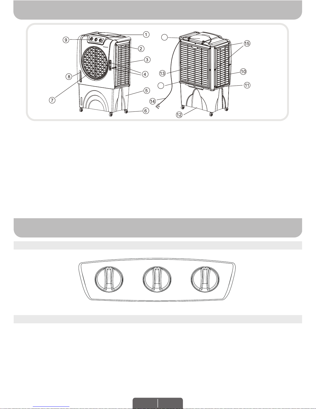
Horizontal Louvers
Water Level Indicator
Control Panel
Right Side Grill
Water Inlet Valve
Drain Plug
Rear Grill
Power Cord & Plug
Rear Grill Screws
Water Fill Door
Honeycomb Cooling Media
(Media is on 3 sides)
Water Inlet Hole
Handle
Left Side Grill
Lever for Horizontal Louvers
Water Tank
Casters
PARTS DESCRIPTION
USE & OPERATION
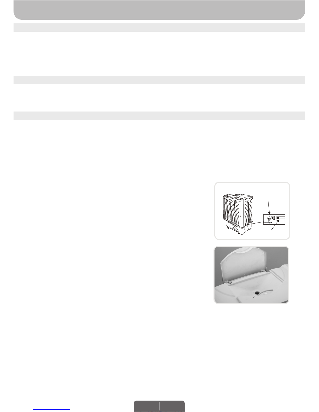
CONTROL PANEL
FUNCTION BUTTONS
SPEED / ON - OFF
Connect to the power supply and turn the SPEED knob. The fan will start. Change the speed from
3 to 1 (1 for Low, 2 for Medium and 3 for High fan speed). To switch OFF the unit, turn the SPEED
knob to 0.
COOL
You must add water before operating the unit on Cool mode. Turn the COOL knob to the ON
position to activate evaporative cooling. The water pump will operate and you will feel the cooler
air after the Honeycomb Cooling Media is completely wet.
WARNING -- READ AND SAVE THE AIR COOLER SAFETY & MAINTENANCE GUIDE AND USER
MANUAL BEFORE USING THIS PRODUCT. FAILURE TO FOLLOW THESE INSTRUCTIONS MAY
DAMAGE AND/ OR IMPAIR ITS OPERATION AND VOID THE WARRANTY. IN CASE THERE IS
ANY INCONSISTENCY OR CONFLICT BETWEEN THE ENGLISH VERSION AND ANY OTHER
LANGUAGE VERSION OF THE CONTENT OF THIS MATERIAL, THE ENGLISH VERSION SHALL
PREVAIL.
EN 1
1)
2)
3)
4)
5)
6)
7)
8)
9)
10)
11)
12)
13)
14)
15)
16)
17)
OFF
COOL
ON
OFF
SWING
ON
SPEED
0
3
2
1
Page 3
USE & OPERATION (CONTINUED)
FILLING WITH WATER
COOLER LOCATION
It is ideal to use the Continuous Water Supply Connection to run the unit for long periods of time
without refilling the tank. This also helps prevent pump failure in case the cooler is running with
inadequate water in the tank.
Make sure to position the air cooler correctly before you set up and start using the product.
Please refer to the COOLER LOCATION section of the separate Safety & Maintenance Guide.
FUNCTION BUTTONS (CONTINUED)
SWING
Turn the SWING knob to the ON position to activate the movement of the louvers. The louvers will
begin to move left to right automatically. Vertical Air Flow - You can manually adjust the lever
located at the front of the unit to change vertical air flow.
Locate the male connector at one end of the garden hose. Insert
the garden hose connector into the water inlet valve of the cooler.
Screw and tighten the water inlet valve onto the threaded part of
the garden hose connector, making sure the hose connector is
secured to ensure there will be no leaks. If there is leakage, the
hose and the water inlet valve may not be connected properly. Try
to disconnect, replace and tighten the water inlet valve again.
When the connection is secured, turn ON the water supply and
the water will flow into the water tank of the cooler.
The cooler is now set so the water refills automatically when the
water tank is empty, or when the water reaches below a minimum
level.
When the water tank is full, the water inlet valve will automatically
stop the water supply from overflowing.
Please open the water valve for minimum flow as too much
pressure could damage the inlet pressure control system.
WARNING: The maximum water inlet pressure is 0.5 MPa.
•
•
•
•
•
Using a portable container or a garden hose, you can refill the water tank manually by pouring
water into the water tank through the water inlet hole located at the top of the air cooler.
Check the water level indicator to know when the water tank is full. Do not fill water above the
"Max." water level mark to avoid water droplets collecting on the louvers.
•
•
Manual Water Tank Refill:
Water inlet valve
Garden Hose
Continuous Water Supply Connection:
For a continuous water supply, you will need a garden hose that is
connected to a main water supply.
EN 2
Water Inlet Hole
Water Fill Door
Ice Loading
Compartment
CAUTION: Unplug the unit from the electrical power outlet before filling or emptying the water tank.
Page 4

USE & OPERATION (CONTINUED)
FILLING WITH WATER (CONTINUED)
CLEANING & DRAINING THE WATER TANK
Move the unit to a location where the water can be drained. Remove the cap from the Drain plug
located at the bottom of the unit. Allow the tank to empty.
Refill the water tank with clean water, up to the maximum level and drain it completely.
Use a damp cloth to remove the dirt and dust from the surface of the unit. Never use corrosive
elements or chemicals to clean this product.
When the product is not in use, store the unit in a dry place away from direct sunlight.
•
•
•
•
WARNING: Always ensure the water in the water tank is above the minimum (Min.) water level
mark for both Continuous & Manual Water Refill. Running the unit in Cool mode with
inadequate water may cause pump failure.
NOTE: The water capacity refers to the total volume of water that can be contained within the
air cooler water tank and water distribution system. The water capacity in the tank at the “Max.”
indicator level may be lower than the actual water capacity of the air cooler.
WARNING: Do not fill water tank with dirty water or salt water. This can damage the unit and
Honeycomb media.
WARNING:
Before cleaning the unit, switch the unit OFF and disconnect from the electrical socket.
If the cooler will not be used for a long period of time, please refer to the STORAGE & MAINTENANCE GUIDELINES located in the separate Safety & Maintenance Guide.
EN 3
Page 5

USE & OPERATION (CONTINUED)
Remove the screws from the Rear Grill of the Air Cooler.
Carefully pull out the Rear Grill from the Air Cooler.
The Honeycomb Cooling Pad is secured on the Rear Grill by two Horizontal Bars that are fixed
in place by two screws on the Left and Right Sides of these Horizontal Bars. Remove these
screws to release the Horizontal Bars.
Pull out the Honeycomb Cooling Pad by sliding it out from the Rear Grill. Replace with the new
Honeycomb Cooling Pad by sliding into the grooves of the Rear Grill until it fits comfortably
and securely in place on the grill. Replace the Horizontal Bars back onto the Rear Grill by
replacing the Left and Right Side screws and tightening them in place. This secures the
Honeycomb Cooling Pad in place on the Rear Grill.
Repeat steps 1 to 4 to remove the Honeycomb Cooling Pad on the Left and Right Side Grills.
WARNING: DO NOT operate the Air Cooler when any or all of the Rear or Side Grills are removed
from the Air Cooler, or if there is a loose-fitting Rear or Side Grill. Doing so can cause serious
injury or dangerous electrical shock.
1.
2.
3.
4.
5.
Removing the Honeycomb Cooling Media:
CLEANING THE HONEYCOMB COOLING MEDIA
The appliance is supplied with three Honeycomb Cooling Media pads.
The Honeycomb Cooling Media are located inside the Rear and Side Grills. Follow Steps 1 to 5
for instructions on how to remove them from the unit for cleaning and maintenance.
Do not run the unit in COOL mode with stale water in the tank. You must empty the water tank
and refill with fresh water, especially if the tank has not been cleaned in a long time.
The cleaning frequency for the Honeycomb media depends on local air and water conditions. In
areas where the mineral content of water is high, mineral deposits may build up on the
Honeycomb Cooling Media and restrict air flow. Draining the water tank and refilling with fresh
water at least once a week will help reduce mineral deposits. If mineral deposits remain on the
Honeycomb Cooling Media, the media should be removed and washed under fresh water. The
media should be cleaned every two months or sooner, depending on your needs.
For best results allow the Honeycomb Cooling Media to dry after each use by turning off the
cool function 15 minutes before turning the unit off.
•
•
•
•
•
Step 1:
Step 3: Step 4:
Step 2:
Rear
Honeycomb Pad
Rear Grill
Horizontal
Bars
Screws
Rear
Honeycomb Pad
Rear Grill
Rear Grill
Screws
Rear Grill
EN 4
Page 6

Model
Voltage
Frequency
Cooling Media
Product Dimension
Net Weight
Wattage
Full Water Tank Capacity
TECHNICAL SPECIFICATIONS
ELECTRICAL WIRING DIAGRAM
CL75PM
50Hz
74 Litres
230V
165 Watts
Honeycomb
19.2 Kg
Version: 230V/50Hz
700(L) x 466(W) x 1140(H) mm
27.6(W) x 18.3 (D) x 44.9 (H) in
Page 7

SERVICE AND WARRANTY
This warranty does not apply for:
Liability for consequential loss or damage is neither accepted nor implied.
The warranty is valid only when:
This appliance is warranted for 1 year against all manufacturing defects from the date
of sale. In the event of any complaint, please contact Usha Care at Toll Free No.
1800 1033 111.
The appliance has been installed, used and maintained in accordance with the instruction
manual.
The warranty card and cash memo duly signed by the authorised dealer are to be presented
with the complaint.
The appliance has not been opened or tampered with, by any unauthorised person.
The appliance has been installed, used and maintained in accordance with the instructional
manual. When contacting our Customer Support, please have the information below along
with the proof of purchase. All warranty requests must be accompanied by a proof of
purchase, which is a copy of the original receipt.
1.
2.
3.
4.
Damages due to chipping, peeling, plating and denting.
Breakage or damage to components made out of Bakelite, Urea, ABS, SAN and
such plastic materials, rubber parts and cord.
Normal wear and tear of parts.
Damage resulting from accidents, mishandling or negligence on part of the customer.
1.
2.
3.
4.
Liability for consequential loss or damages:
The Company will not be liable for any loss or damage arising/resulting from indirect or
consequential loss or damages.
The Company aggregate liability in respect of all claims under the Warranty shall not exceed
the original purchase price of the Product or, at Company’s option, replacement of the
Product with a like or similar Product.
The Company excludes all other warranties, conditions, terms, representations and
undertakings whether express or implied.
1.
2.
3.
Jurisdiction:
The courts at Delhi shall have exclusive jurisdiction to resolve any disputes between the
parties arising under Terms and Conditions of Warranty.
1.
S.NO
CASH MEMO
DATE
DEALET’S NAME AND ADDRESS
OWNER’S NAME & ADDRESS
......................................................................................................
......................................................................................................
......................................................................................................
......................................................................................................
......................................................................................................
......................................................................................................
......................................................................................................
......................................................................................................
......................................................................................................
:
:
:
:
:
Page 8

© 2016 JMATEK Limited. All rights reserved.
The Honeywell Trademark is used under license from Honeywell International Inc.
Honeywell International Inc. makes no representations or warranties with respect to this product.
Manufactured by Dynamic Industries: 40th KM, Delhi – Jaipur Highway,Vill. Narsinghpur,
P.O. Box Kherki Daula,Gurgaon – 122 004, Haryana, India.
Manufactured under supervision of JMATEK India Private Ltd.
 Loading...