


TV-2-U
Table of contents
 Loading...
TM 11-6625-316-12
DEPARTMENT OF THE ARMY TECHNlCAL MANUAL
OPERATOR AND ORGANIZATIONAL
MAINTENANCE MANUAL
TEST SETS
ELECTRON TUBE
TV-2/U, TV-2A/U
AND TV-2B/U
This copy is a reprint which includes current
pages from Changes 2 through 3
HEADQUARTERS, DEPARTMENT OF THE ARMY
MARCH 1961

WARNING
DANGEROUS VOLTAGES EXIST IN THIS EQUIPMENT
Be careful when working on the 290-volt plate and screen supply
circuits, or on the 115-volt ac line connections.
DON’T TAKE CHANCES!


Changes now in force: C 2 and C 3
TM 11-6625-316-12
C3
CHANGE
HEADQUARTERS
DEPARTMENT OF THE ARMY
No. 3
Operator and Organizational Maintenance Manual
TEST SETS, ELECTRON TUBE
TV-2/U, TV-2A/U, TV-2B/U, AND TV-2C/U
WASHINGTON, D. C., 10 July 1974
TM 11-6625-316-12, 16 March 1961, is changed as follows:
Page 5, paragraph 1.1. Delete and substitute:
1.1 Indexes of Publications
a. DA Pam 310-4. Refer to the latest issue of DA Pam 310-4
to determine whether there are new editions, changes, or additional publications pertaining to the equipment.
DA Pam 310.7. Refer to DA Pam 310-7 to determine whether
b.
there are modification work orders (MWO’S) pertaining to the
equipment.
Paragraph 2. Delete and substitute the following:
2. Forms and Records
a. Reports of Maintenance and
Unsatisfactory Equipment,
Maintenance forms, records, and reports which are to be used by
maintenance personnel at all maintenance levels are listed in and
prescribed by TM 38-750.
b. Report of Packaging and Handing Deficiencies. Fill out and
forward DD Form 6 (Report of Packaging and Handling De-
ficiencies) as prescribed in AR 700-58/NAVSUP PUB 378/AFR
71-4/MCO P4030.29, and DSAR 4145.8.
c. Discrepancy in Shipment Report (DISREP) (SF 361). Fill
out and forward Discrepancy in Shipment Report (DISREP)
(SF 361) as prescribed in AR 55-38/NAVSUPINST 4610.33/
AFM 75-18/MCO P4610.19A, and DSAR 4500.15.
2.1 Reporting of Errors
The reporting of errors, omissions, and recommendations for improving this Duplication by the individual user is encouraged.
1

Reports should be submitted on DA Form 2028 (Recommended
Changes to Publications and Blank Forms) and forwarded direct
to Commander, US Army Electronics Command, ATTN: AMSEL-
MA-C, Fort Monmouth, NJ 07703.
Page 7, paragraph 5.
Delete and substitute:
5. Item Comprising an Operable Equipment
Test Sets, Electron Tube TV-2/U, TV-2A/U, TV-2B/U, and
TV-2C/U (6625-669-0263) each comprises an operable equipment,
Page
11, paragraph 9c. Delete the second sentence.
Page
61, appendix III. Delete appendix III in it’s
eluding final foldout, entitled: Items Comprising
entirety (in-
an Operable
Equipment).
By Order of the Secretary of the
Official:
VERNE L. BOWERS
Major General, United States
The Adjutant General
Distribution:
Active Army:
USASA (2)
CNGB (1)
ACSC-E (2)
Dir of Trans (1)
COE (1)
TSG (1)
USAARENBD (1)
USAMB (10)
AMC (1)
MICOM (2)
TECOM (2)
TRADOC (2)
ARADCOM (2)
ARADCOM Rgn (2)
OS Maj Cored (4)
LOGCOMD (3)
USACC (4)
MDW (1)
Armies (2)
Army:
CREIGHTON W. ABRAMS
General, United States Army
Chief of Staff
Army
Corps (2)
HISA (Ft Monmouth) (18)
Ft Gordon (10)
Ft Huachuca (10)
Ft Carson (5)
Ft Richardson (ECOM Oft) (2)
WSMR (1)
Svc Colleges (1)
USASESS (15)
USAINTCS (3)
USAADS (2)
USAFAS (2)
USAARMS (2)
USAIS (2)
USAES (2)
AD (1) except
SAAD (30)
LBAD (14)
TOAD (14)
2

ATAD (10)
USA Dep (2)
Sig Sec USA Dep (2)
Sig Dep (2)
MAAG (1)
USARMIS (1)
ATS (1)
WRAMC (1)
USAERDAA (1)
USAERDAW (1)
Sig FLDMS (1)
Units org under fol TOE: 1 ea.
7
7-100
11-16
11-36
11-97
11-98
11-117
11-302
17
29-1
29-15
29-16
29-21
29-26
29-26
29-36
29-55
29-56
29-105
29-109
29-134
29-186
32-56
37
39-51
55-157
57
57-100
11-500 (AA-AC)
ARNG: State AG (3).
USAR: None
For explanation of abbreviations used, see AR 310-50.


* TM 11-6625-316-12
T ECHNICAL M ANUAL
No. 11-6625-316-12
T
ECHNICAL O RDER
DEPARTMENTS OF THE ARMY
AND THE AIR FORCE
W
ASHINGTON 25, D. C., 16 March 1961
TEST SETS, ELECTRON TUBE TV-2/U, TV-2A/U,
AND TV-2 B/U
C HAPTER 1.
Section I.
HAPTER 2.
C
Section I.
INTRODUCTION
Genera’
Scope _ _ _ _ _ _ _ _ _ _ _ _ _ _ _ _ _ _ _ _ _
Forms and records _ _ _ _ _ _ _ _ _ _ _ _ _ _ _ _ _ _ _
II.
Description and data
Purpose and use _ _ _ _ _ _ _ _ _ _ _ _ _ _ _
Technical characteristics _ _ _ _ _ _ _ _ _ _ _ _ _ _ _ _ _ _
Components of Test Set, Electron Tube
TV-2(*)/U.
Description of Test Set, Electron Tube
TV-2(*)/U.
Differences in models _ _ _ _ _ _ _ _ _ _
OPERATION
Service upon receipt of equipment
Unpacking _ _ _ _ _ _ _ _ _ _ _ _ _ _ _ _ _ _
Checking unpacked equipment _ _ _ _ _ _ _ _ _ _ _ _
II.
Operator’s controls and indicators _ _ _ _ _ _ _ _ _
Damage from improper settings _ _ _ _ _ _ _ _ _
Operating controls and indicators _ _ _ _ _ _ _
Tube test data _ _ _ _ _ _ _ _ _ _ _ _ _ _ _ _ _ _ _ _ _ _
Preliminary operating procedures
III.
Operating precautions _ _ _ _ _ _ _ _ _ _ _ _ _ _ _ _ _
Tube test sockets and test adapters _ _ _ _ _ _ _ _ _ _ _ _
Preliminary starting procedure _ _ _ _ _ _ _ _ _ _ _
Operation under usual conditions
IV.
Starting procedures _ _ _ _ _ _ _ _ _ _ _ _ _ _ _ _ _ _
Zero adjustment of PERCENT QUALITY
meter.
Paragraph
1
2
3
4
5
6
7
8
9
10
11
12
13
14
15
16
17
Page
5
5
6
6
7
8
8
10
10
12
12
16
19
19
20
22
23
This manual supersedes so much of TM 11-2661, 11 May 1955, including
C4, 8 November 1957; C5, 21 April 1958; C6, 15 May 1959, as pertains to
operator’s and organizational maintenance and so much of TM 11-6625-316-
12P, 23 July 1959, as pertains to the basic issue items list and the maintenance
allocation chart.
1

Section IV.
C
HAPTER 3.
Section I.
A
PPENDIX I.
Short test _ _ _ _ _ _ _ _ _ _ _ _ _ _ _ _ _ _ _ _ _ _ _ _ _ _ _ _ _ _ _ _ _ _ _
Interelement leakage test _ _ _ _ _ _ _ _ _ _ _ _ _
Filament continuity test _ _ _ _ _ _ _ _ _ _ _ _ _ _ _ _ _ _
Transconductance test _ _ _ _ _ _ _ _ _ _ _ _ _ _ _ _ _ _ _ _ _ _ _ _
Gas test _ _ _ _ _ _ _ _ _ _ _ _ _ _ _ _ _ _ _ _ _ _ _ _ _ _ _ _ _ _ _ _ _ _ _ _ _
Emission test _ _ _ _ _ _ _ _ _ _ _ _ _ _ _ _ _ _ _ _ _ _ _ _ _ _ _ _ _ _ _ _
Voltage regulator and gas rectifier test _ _ _ _ _ _
Procedure for reading plate current (less than
18
19
20
21
22
23
24
25
50 milliamperes) of triode tubes.
Thyratron test _ _ _ _ _ _ _ _ _ _ _ _ _ _ _ _ _
Electron-ray indicator test _ _ _ _ _ _ _ _ _ _ _ _ _ _ _
Ballast tube test _ _ _ _ _ _ _ _ _ _ _ _ _ _ _
Indicator lamp test _ _ _ _ _ _ _ _ _ _ _ _ _ _ _ _ _ _ _ _ _ _ _ _ _ _ _
Complete tube test _ _ _ _ _ _ _ _ _ _ _ _ _ _ _ _ _ _ _
Stopping procedure _ _ _ _ _ _ _ _ _ _ _ _ _ _
26
27
28
29
30
31
PERATOR’S MAINTENANCE
General _ _ _ _ _ _ _ _ _ _ _ _ _ _ _ _ _ _ _ _ _ _ _ _ _ _ _ _ _ _ _
Preventive maintenance_ _ _ _ _ _ _ _ _ _ _ _ _ _ _ _ _ _
Visual inspection _ _ _ _ _ _ _ _ _ _ _ _ _ _ _ _ _ _ _ _ _ _ _ _ _ _ _ _
Operational checklist _ _ _ _ _ _ _ _ _ _ _ _ _
Removal and replacement of chassis _ _ _ _ _ _ _ _ _ _ _ _
Tube replacement _ _ _ _ _ _ _ _ _ _ _ _ _ _ _ _ _ _ _ _ _ _ _
Preferred-type tubes _ _ _ _ _ _ _ _ _ _ _ _ _ _ _ _ _ _ _ _ _
Replacement of fuses and lamps _ _ _ _ _ _ _ _ _ _ _ _
4.
ORGANIZATIONAL MAINTENANCE
General _ _ _ _ _ _ _ _ _ _ _ _ _ _ _ _ _ _ _ _ _ _ _ _
Tools and materials require _ _ _ _ _ _ _ _ _ _ _ _ _ _
Preventive maintenance _ _ _ _ _ _ _ _ _ _ _ _
Visual inspection _ _ _ _ _ _ _ _ _ _ _ _ _ _ _ _ _ _
Equipment performance checklist _ _ _ _ _ _ _ _ _ _ _ _ _
Replacement of test adapters _ _ _ _ _ _ _ _ _ _ _ _ _ _ _
5.
SHIPMENT, LIMITED STORAGE, AND
32
33
34
35
36
37
38
39
40
41
42
43
44
45
DEMOLITION TO PREVENT ENEMY
USE.
Shipment and limited storage
Disassembly of equipment _ _ _ _ _ _ _ _ _ _ _ _ _ _ _ _ _
Repackaging for shipment or limited storage
II.
Demolition of materiel to prevent enemy use
Authority for demolition
Methods of destruction _ _ _ _ _ _ _ _ _
REFERENCES_ _ _ _ _ _ _ _ _ _ _ _ _ _ _ _ _
II.
MAINTENANCE ALLOCATION _ _ _ _ _ _ _ _ _ _ _ _ _
III.
BASIC ISSUE ITEMS LIST _ _ _ _ _ _ _ _ _ _ _ _ _ _ _ _ _
46
47
48
49
--
--
--
23
24
25
25
26
27
28
29
30
31
32
32
33
37
38
38
41
41
44
45
45
46
47
47
47
48
48
54
55
55
57
57
58
59
64
2


Figure 1.
4

CHAPTER 1
INTRODUCTION
Section I. GENERAL
1. Scope
a. This manual describes Test Sets, Electron Tube TV-2/U,
TV–2A/U, and TV–2B/U (fig. 1) and covers operation and the
operator’s and organizational maintenance. It includes instructions for operation under usual conditions, for cleaning and inspection of the equipment, and for replacement of parts available
to first and second echelon maintenance.
b. Official nomenclature followed by (*) is used to indicate all
models of the equipment item covered in this manual. Thus Test
Set, Electron Tube TV–2 (*)/U represents Test Sets, Electron
Tube TV-2/U, TV–2A/U, and TV-2B/U.
c. Throughout this manual, Test Set, Electron Tube TV–2 ( * ) /U
is referred to as the tube tester.
2. Forms and Records
a. Unsatisfactory Equipment Report. Fill out and forward DD
Form 787–1 (Electronic Failure Report, Signal Equipment) to the
Commanding Officer, U.S. Army Signal Materiel Support Agency,
ATTN: SIGMS–ML, Fort Monmouth, N. J., as prescribed in AR
700-39.
b. Report of Damaged or Improper Shipment. Fill out and forward DD Form 6 (Report of Damaged or Improper Shipment)
as prescribed in AR 700–58.
c. Preventive Maintenance Forms. Prepare DA Form 11–266
(figs. 6, 7, and 9) (Maintenance Check List for Signal Equipment
(Test Equipment) ) in accordance with instructions on the form.
d. Parts List Form. Forward DA Form 2028 (Recommended
Changes to DA Technical Manual Parts Lists or Supply Manuals
7, 8, or 9), directly to the Commanding Officer, U.S. Army Signal
Materiel Support Agency, ATTN: SIGMS-ML Fort Monmouth,
N. J., with comments on parts listings.
e. Comments on Manual. Forward all other comments on this
publication directly to the Commanding Officer, U.S. Army Signal
5

Materiel Support Agency, ATTN: SIGMS-PA2d, Fort Monmouth,
N.J.
Section II. DESCRIPTION AND DATA
3. Purpose and Use
Test Set, Electron Tube TV–2(*)/U (fig. 1) is a portable tube
tester of the dynamic mutual conductance type. It is used to test
and to measure performance capabilities and to determine rejection limit for electron tubes used in receivers, low-powered transmitters, and other electronic equipment. The following tests can
be made with the tube tester.
a. Short test.
b. Interelement leakage test.
c. Filament continuity test.
d. Dynamic mutual conductance test for amplifier tubes.
e. Gas test for amplifier tubes.
f. Emission test for vacuum rectifier tubes.
g. Test of gas rectifier tubes.
h. Test of voltage regulator tubes.
i. Plate current tests for triodes.
j. Test of thyratron tubes.
k. Electron-ray indicator test for electronic indicator tubes.
l. Ballast tube test.
4. Technical Characteristics
a. Power supply:
Input voltage ________________ 103.5 to 126.5 volts ac.
Frequency------------------------ 50 to 1,000 cps, single-phase.
Power consumption -------------70 watts (no tube under test).
Temperature range ----------- Satisfactory operation from -4° F. to 125° F.
b. Meters:
FILAMENT VOLTS meter:
Type------------------------------ Dc voltmeter movement.
Frequency range ----------- 50 to 1,000 cps.
Ac voltage ranges -------------- 0 to 2.5 volts, 0 to 10 volts, 0 to 40 volts, and
0 to 120 volts. Redlines at 0.625, 6.3, 12.6,
and 117 on appropriate scale.
Accuracy -------------------------- ±5 percent error at full scale.
GRID BIAS VOLTS meter:
Type ---------------------------------Dc voltmeter.
Sensitivity ---------------- 1,000 ohms per volt.
Dc voltage ranges ---------- 0 to 5 volts, 0 to 10 volts, and 0 to 50 volts.
Accuracy-------------------------- ±2 percent error at full scale.
6

PLATE
SCREEN VOLTS meter:
meter:
Type _ _ _ _ _ _ _ _ _ _ _ _ _ _ _ _ _ _ _ _ _ DC voltmeter.
Sensitivity ----------------- 1,000 ohms per volt.
Voltage ranges. ---------------0 to 250 volts dc, with redlines at 45, 90, 180,
and 225.
0 to 50 volts ac, with 20 AC and 35 AC marked
Ohmmeter ranges
Accuracy--------------
Type ---------Sensitivity -----------------1,000 ohms per volt.
Voltage range ------------- 0 to 250 volts dc.
Accuracy-------------
------------0.1 to 1.0 megohms.
±2 percent error at full scale.
-------------Dc voltmeter.
in red.
±2 percent error at full scale.
SIGNAL meter:
Type--------------------- Ac iron vane-type ammeter.
Frequency range--------.50 to 1,000 cps.
Meter range
Accuracy----------------
PERCENT QUALITY meter (transconductance):
Type------------------------ Dc microammeter.
Sensitivity-------------------10,000 ohms per volt (150 microamperes full-
Percent quality ranges ------------ To 60,000 micromhos (in equivalent percentage
Accuracy __________________ ±2 percent error at full scale.
------------45 ma ac full scale; redline at approximately
two-thirds full scale (35 ma ac).
±5 percent error at full scale.
scale deflection).
values).
c. Number of electron tubes -------------------------- 3
5. Components of Test Set, Electron Tube TV-2(*)/U
TM 11-6625-816-12
7

b. Running Spares.
Quantity Item
1
1
5 Fuses,
1
Note. Running spares listed above are stored in designated positions on the inside cover and
chassis (figs. 1 and 8 ) of the tube tester.
Electron tube, 83------------------------------ V1
Electron tube,
inches.
Glow lamp, NE-51 _ _ _ _ _ _ _ _ _ _ _ _ _ _ _ _ _ _ _ _ 11C, 12C
6X4W----------------------------- V2, V3
3 ampere, 250 volts, ¼ x 1¼ F1, F2
Ref symbol
6. Description of Test Set, Electron Tube TV-2(*)/U
(fig. 1)
a. Test Set, Electron Tube TV-2(*)/U (tube tester) is housed
in a carrying case equipped with a carrying handle, two electrical
clips for connection to the top cap of a tube under test, operating
and spare tubes, fuses, indicating lamps, and miniature tube pin
straighteners. The cover is secured to the case by luggage-type
fasteners. Power cord brackets and a dummy power cord receptacle on the panel are used to secure and store the power cable.
Tube test data is given on a roll chart; the roll chart case is
mounted inside the cover of the tube tester. A condensed summary
of operating instructions also is mounted inside the cover of the
tube tester. The cover is hinged by slip hinges and can be removed
from the case. Two handles attached to the panel permit easy
lifting of the tube tester from the case.
b. All indicating meters, switches, controls, and tube test sockets
are located on the panel of the equipment. The necessary data for
setting and operating the controls to test the various tube types
are contained in the tube test data roll chart (a above). Two
electrical clips (A and B, fig. 3) provide connection to external
caps of tubes as reqired. One end of the power cord is permanently attached to the panel; the other end terminates in a male
plug.
7. Differences in Models
Test Sets, Electron Tube TV-2/U, TV-2A/U, and TV-2B/U
are similar in purpose, operation, and appearance. On some equipments, the FUNCTION switch and the FIL. CONT. SHORT lamp
are marked LEAKAGE VR and SHORT, respectively. Other
external differences among models of the tube tester are shown
below.
8

9

CHAPTER 2
OPERATION
Section I. SERVICE UPON RECEIPT OF EQUIPMENT
8. Unpacking
a. Packaging Data. When packed for shipment, the tube tester
is cushioned on all surfaces and placed within a water-resistant
fiberboard box. The fireboard box is sealed with water-resistant
tape and placed within a wooden shipping box. Spare tubes, lamps,
and fuses are placed in their designated positions within the tube
tester (figs. 1 and 8), The technical manuals are packed within a
close-fitting bag fabricated of waterproof wrapping paper. The
bag is securely sealed with waterproof pressure-sensitive tape.
The wooden shipping box is strapped only for intertheater shipment. A typical wooden shipping box and its contents are shown
in figure 2.
(1) The inside dimensions of a wooden shipping box that
contains a tube tester is approximately 19¼ by 18¼ by
10¾ inches.
(2) The outside volume of the tube tester packed in a wooden
shipping box is 2.16 cubic feet, and weighs 60 pounds.
b. Removing Contents.
(1) Cut and fold back the metal straps.
(2) Remove the nails from the top with a nailpuller and
remove the wooden top.
(3) Do not attempt to pry off the top; prying may damage the
equipment.
(4) Remove the fiberboard box and cut through the three
edges of the box and remove the contents.
9. Checking Unpacked Equipment
a. Check the equipment for any loss or damage that might have
occurred during shipment. If the equipment has been damaged or
is incomplete, refer to paragraph 2.
b. If the equipment has been used or reconditioned, see whether
it has been changed by a Modification Work Order (MWO). If
10
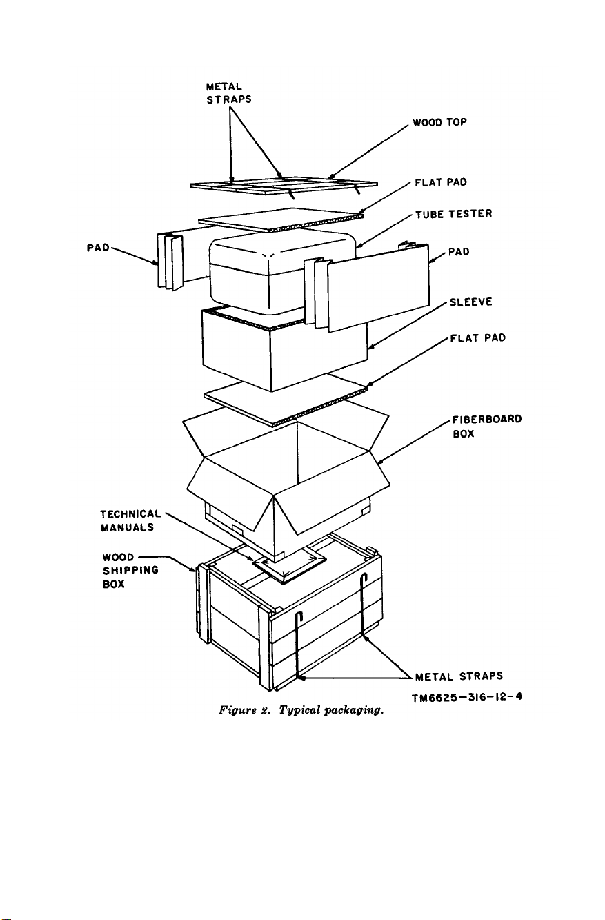
Figure 2.
modified, the MWO number will appear on the front panel near the
nomenclature plate.
c. Check the equipment against the packing list. When no
packing list accompanies the equipment, use the table of components (par. 5a) and/or the basic issue items list (app. III) as a
general check.
11
Loading...