

U.S. Boiler Company K2FT-085, K2FT-110, K2FT-270, K2FTC-155, K2FT-205 Installation, Operating And Service Instructions
...
INSTALLATION, OPERATING AND
SERVICE INSTRUCTIONS FOR
K2FT™
CONDENSING HIGH EFFICIENCY
DIRECT VENT
GAS - FIRED HOT WATER BOILER
9700609
Space Heating Models:
• K2FT-085
• K2FT-110
• K2FT-155
• K2FT-205
• K2FT-270
Combi Domestic Hot Water
and Space Heating Model:
• K2FTC-155
As an ENERGY STAR
STAR® guidelines for energy efciency established by the United States Environmental Protection Agency (EPA).
®
Partner, U.S. Boiler Company has determined that the K2FT™ Series meets the ENERGY
Improper installation, adjustment, alteration, service or maintenance can cause property damage, injury, or
loss of life. For assistance or additional information, consult a qualied installer, service agency or the gas
supplier. This boiler requires a special venting system. Read these instructions carefully before installing.
106375-01 - 4/16
WARNING
Price - $5.00
1

IMPORTANT INFORMATION - READ CAREFULLY
NOTE: The equipment shall be installed in accordance with those installation regulations enforced in the area where the
installation is to be made. These regulations shall be carefully followed in all cases. Authorities having jurisdiction
shall be consulted before installations are made.
All wiring on boilers installed in the USA shall be made in accordance with the National Electrical Code and/or local
regulations.
All wiring on boilers installed in Canada shall be made in accordance with the Canadian Electrical Code and/or local
regulations.
The City of New York requires a Licensed Master Plumber supervise the installation of this product.
The Massachusetts Board of Plumbers and Gas Fitters has approved the K2FT™ Series boiler. See the Massachusetts Board
of Plumbers and Gas Fitters website, http://license.reg.state.ma.us/pubLic/pl_products/pb_pre_form.asp for the latest Approval
Code or ask your local Sales Representative.
The Commonwealth of Massachusetts requires this product to be installed by a Licensed Plumber or Gas Fitter.
The following terms are used throughout this manual to bring attention to the presence of hazards of various risk levels,
or to important information concerning product life.
DANGER
Indicates an imminently hazardous situation
which, if not avoided, will result in death, serious
injury or substantial property damage.
Indicates a potentially hazardous situation which,
if not avoided, may result in moderate or minor
injury or property damage.
CAUTION
NOTICE
WARNING
Indicates a potentially hazardous situation which,
if not avoided, could result in death, serious injury
or substantial property damage.
Indicates special instructions on installation,
operation, or maintenance which are important
but not related to personal injury hazards.
DANGER
Explosion Hazard. DO NOT store or use gasoline or other ammable vapors or liquids in the vicinity of this
or any other appliance.
If you smell gas vapors, NO NOT try to operate any appliance - DO NOT touch any electrical switch or use
any phone in the building. Immediately, call the gas supplier from a remotely located phone. Follow the gas
supplier’s instructions or if the supplier is unavailable, contact the re department.
WARNING
This boiler must only be serviced and repaired by skilled and experienced service technicians.
If any controls are replaced, they must be replaced with identical models.
Read, understand and follow all the instructions and warnings contained in all the sections of this
manual.
If any electrical wires are disconnected during service, clearly label the wires and assure that the wires
are reconnected properly.
Never jump out or bypass any safety or operating control or component of this boiler.
Assure that all safety and operating controls and components are operating properly before placing
the boiler back in service.
Annually inspect all vent gaskets and replace any exhibiting damage or deterioration.
2
106375-01 - 4/16

WARNING
Asphyxiation Hazard. Fire Hazard. Explosion Hazard. This boiler requires regular maintenance and
service to operate safely. Follow the instructions contained in this manual.
WARNING
Asphyxiation Hazard. This boiler requires regular maintenance and service to operate safely. Follow
the instructions contained in this manual.
Improper installation, adjustment, alteration, service or maintenance can cause property damage,
personal injury or loss of life. Read and understand the entire manual before attempting installation,
start-up operation, or service. Installation and service must be performed only by an experienced,
skilled, and knowledgeable installer or service agency.
This boiler must be properly vented.
This boiler needs fresh air for safe operation and must be installed so there are provisions for
adequate combustion and ventilation air.
Asphyxiation Hazard. The interior of the venting system must be inspected and cleaned before the
start of the heating season and should be inspected periodically throughout the heating season for
any obstructions. A clean and unobstructed venting system is necessary to allow noxious fumes
that could cause injury or loss of life to vent safely and will contribute toward maintaining the boiler’s
efciency.
Installation is not complete unless a safety relief valve is installed in the supply piping. - See the
System Piping Section of this manual for details.
This boiler is supplied with safety devices which may cause the boiler to shut down and not re-start
without service. If damage due to frozen pipes is a possibility, the heating system should not be left
unattended in cold weather; or appropriate safeguards and alarms should be installed on the heating
system to prevent damage if the boiler is inoperative.
Burn Hazard. This boiler contains very hot water under high pressure. Do not unscrew any pipe
ttings nor attempt to disconnect any components of this boiler without positively assuring the water
is cool and has no pressure. Always wear protective clothing and equipment when installing, starting
up or servicing this boiler to prevent scald injuries. Do not rely on the pressure and temperature
gauges to determine the temperature and pressure of the boiler. This boiler contains components
which become very hot when the boiler is operating. Do not touch any components unless they are
cool.
Respiratory Hazard. Boiler materials of construction, products of combustion and the fuel contain
alumina, silica, heavy metals, carbon monoxide, nitrogen oxides, aldehydes and/or other toxic or
harmful substances which can cause death or serious injury and which are known to the state of
California to cause cancer, birth defects and other reproductive harm. Always use proper safety
clothing, respirators and equipment when servicing or working nearby the appliance.
Failure to follow all instructions in the proper order can cause personal injury or death. Read all
instructions, including all those contained in component manufacturers manuals which are provided
with the boiler before installing, starting up, operating, maintaining or servicing.
All cover plates, enclosures and guards must be in place at all times.
Explosion Hazard. Electrical Shock Hazard. Burn Hazard. This boiler uses ammable gas, high
voltage electricity, moving parts, and very hot water under high pressure. Assure that all gas
and electric power supplies are off and that the water temperature is cool before attempting any
disassembly or service.
Do not attempt any service work if gas is present in the air in the vicinity of the boiler. Never modify,
remove or tamper with any control device.
106375-01 - 4/16
DANGER
3

Special Installation Requirements for Massachusetts
A. For all sidewall horizontally vented gas fueled equipment installed in every dwelling, building or structure used in whole
or in part for residential purposes and where the sidewall exhaust vent termination is less than seven (7) ft. above grade, the
following requirements shall be satised:
1. If there is no carbon monoxide detector with an alarm already installed in compliance with the most current edition of
NFPA 720, NFPA 70 and the Massachusetts State Building Code in the residential unit served by the sidewall horizontally
vented gas fueled equipment, a battery operated carbon monoxide detector with an alarm shall be installed in compliance
with the most current edition of NFPA 720, NFPA 70 and the Massachusetts State Building Code.
2. In addition to the above requirements, if there is not one already present, a carbon monoxide detector with an alarm
and a battery back-up shall be installed and located in accordance with the installation requirements supplied with the
detector on the oor level where the gas equipment is installed. The carbon monoxide detector with an alarm shall
comply with 527 CMR, ANSI/UL 2034 Standards or CSA 6.19 and the most current edition of NFPA 720. In the event
that the requirements of this subdivision can not be met at the time of the completion of the installation of the equipment,
the installer shall have a period of thirty (30) days to comply with this requirement; provided, however, that during
said thirty (30) day period, a battery operated carbon monoxide detector with an alarm shall be installed in compliance
with the most current edition of NFPA 720, NFPA 70 and the Massachusetts State Building Code. In the event that the
sidewall horizontally vented gas fueled equipment is installed in a crawl space or an attic, the carbon monoxide detector
may be installed on the next adjacent habitable oor level. Such detector may be a battery operated carbon monoxide
detector with an alarm and shall be installed in compliance with the most current edition of NFPA 720, NFPA 70 and the
Massachusetts State Building Code.
3. A metal or plastic identication plate shall be permanently mounted to the exterior of the building at a minimum
height of eight (8) ft. above grade directly in line with the exhaust vent terminal for the horizontally vented gas fueled
heating appliance or equipment. The sign shall read, in print size no less than one-half (1/2) inch in size, “GAS VENT
DIRECTLY BELOW. KEEP CLEAR OF ALL OBSTRUCTIONS”.
4. A nal inspection by the state or local gas inspector of the sidewall horizontally vented equipment shall not be performed
until proof is provided that the state or local electrical inspector having jurisdiction has granted a permit for installation of
carbon monoxide detectors and alarms as required above.
B. EXEMPTIONS: The following equipment is exempt from 248 CMR 5.08(2)(a) 1 through 4:
1. The equipment listed in Chapter 10 entitled “Equipment Not Required To Be Vented” in the most current edition of NFPA
54 as adopted by the Board; and
2. Product Approved sidewall horizontally vented gas fueled equipment installed in a room or structure separate from the
dwelling, building or structure used in whole or in part for residential purposes.
C. When the manufacturer of Product Approved sidewall horizontally vented gas equipment provides a venting system
design or venting system components with the equipment, the instructions for installation of the equipment and the venting
system shall include:
1. A complete parts list for the venting system design or venting system; and
2. Detailed instructions for the installation of the venting system design or the venting system components.
D. When the manufacturer of a Product Approved sidewall horizontally vented gas fueled equipment does not provide the
parts for venting ue gases, but identies “special venting systems”, the following shall be satised:
1. The referenced “special venting system” instructions shall be included with the appliance or equipment installation
instructions; and
2. The “special venting systems” shall be Product Approved by the Board, and the instructions for that system shall include a
parts list and detailed installation instructions.
E. A copy of all installation instructions for all Product Approved sidewall horizontally vented gas fueled equipment,
all venting instructions, all parts lists for venting instructions, and/or all venting design instructions shall remain with the
appliance or equipment at the completion of the installation.
4
106375-01 - 4/16

WARNINGS FOR THE HOMEOWNER
FOLLOW ALL INSTRUCTIONS and warnings
printed in this manual and posted on the boiler.
MAINTAIN THE BOILER. To keep your boiler safe
and efcient, have a service technician maintain
this boiler as specied in Service and Maintenance
Instructions.
IF YOU ARE NOT QUALIFIED to install or service
boilers, do not install or service this one.
THE BOILER MAY LEAK WATER at the end of
its useful life. Be sure to protect walls, carpets,
and valuables from water that could leak from the
boiler.
PROTECT YOUR HOME IN FREEZING
WEATHER. A power outage, safety lockout, or
component failure will prevent your boiler from
lighting. In winter, your pipes may freeze and
cause extensive property damage. Do not leave
the heating system unattended during cold weather
unless alarms or other safeguards are in place to
prevent such damage.
DO NOT BLOCK AIR FLOW into or around the
boiler. Insufcient air may cause the boiler to
produce carbon monoxide or start a re.
KEEP FLAMMABLE LIQUIDS AWAY from the
boiler, including paint, solvents, and gasoline.
The boiler may ignite the vapors from the liquids
causing explosion or re.
KEEP CHILDREN AND PETS away from hot
surfaces of the boiler, boiler piping, vent piping and
vent terminals.
CARBON MONOXIDE (CO) is an odorless, deadly
gas that may be introduced into your home by
any malfunctioning fuel-burning product or vent
system failure. Consider installing CO alarms near
bedrooms in all levels of the building to warn you
and your family of potential CO exposure.
WARNINGS FOR THE INSTALLER
READ THIS ENTIRE MANUAL before attempting
installation, start-up, or service. Improper
installation, adjustment, alteration, service, or
maintenance may cause serious property damage,
personal injury, or death.
DO NOT DISCONNECT PIPE FITTINGS on the
boiler or in the heating system without rst verifying
that the system is cool and free of pressure and
that your clothing will protect you from a release
of hot water or steam. Do not rely solely on the
boiler’s temperature and pressure gage when
making this judgment.
USE PROPER PERSONAL PROTECTION
EQUIPMENT when servicing or working near the
boiler. Materials of construction, ue products, and
fuel contain alumina, silica, heavy metals, carbon
monoxide, nitrogen oxides, and/or other toxic or
harmful substances that can are hazardous to
health and life and that are known to the State of
California to cause cancer, birth defects, and other
reproductive harm.
INSTALL ALL GUARDS, cover plates, and
enclosures before operating the boiler.
SIZE THE BOILER PROPERLY relative to the
design heat load or, if using domestic hot water
priority, the peak hot water load, whichever
is larger. A grossly oversized boiler will cycle
excessively and this will lead to premature failure
of the boiler and its components. Our warranty
does not apply to damage from excessive cycling.
ADHERE TO ALL LOCAL CODE
REQUIREMENTS. Contact your local code
inspector prior to installation. In the absence of
a local code, adhere to the National Fuel Gas
Code ANSI Z223.1/NFPA 54 or CAN/CSA B149.1,
Natural Gas and Propane Installation Code.
ALL WIRING must comply with the National
Electrical Code ANSI/NFPA 70 (in the USA) or the
Canadian Electrical Code CSA C22.1 (in Canada)
and any local regulations.
106375-01 - 4/16
5

Table of Contents
I. Product Description 7
II. Specications 7
III. Before Installing 9
IV. Locating The Boiler 10
V. Mounting The Boiler 12
VI. Air For Ventilation 15
VII. Venting 16
A. Vent System Design 16
B. Design Requirements Unique to Horizontal Twin Pipe Venting Systems 22
C. Design Requirements Unique to Vertical Venting Systems 28
D. Design Requirements Unique to Split Vent Systems 36
E. Assembly of CPVC/PVC Vent Systems 43
F. Assembly of DuraVent PolyPro Vent Systems 50
G. Assembly of Selkirk Polyue Vent Systems 55
H. Assembly of Centrotherm InnoFlue Vent Systems 59
I. Condensate Trap and Drain 62
J. Removing An Existing Boiler From Common Chimney 64
VIII. Gas Piping 65
IX. System Piping 67
A. General System Piping Precaution 67
B. Standard Piping Installation Requirements 68
C. Near Boiler Piping Design 70
D. Piping For Special Situations 81
X. Wiring 82
XI. Start-Up and Checkout 92
XII. Operation 99
XIII. Service and Maintenance 128
XIV. Troubleshooting 135
XV. Repair Parts 141
Appendix A: LP Gas Conversion Instructions 156
Appendix B: Instructions for High Altitude Installation
Above 4,500 ft. 160
Appendix C: K2FTC-155 Combi Instruction Manual 164
Appendix D: Special Requirements For Side-Wall
Vented Appliances In The Commonwealth
of Massachusetts 174
6
106375-01 - 4/16

I. Product Description
This boiler is a stainless steel gas red condensing boiler designed for use in forced hot water heating systems requiring
supply water temperatures of 180°F or less. It is designed for installation on a wall. This boiler may be vented vertically or
horizontally with combustion air supplied from outdoors. It is not designed for use in gravity hot water systems or systems
containing signicant amounts of dissolved oxygen.
Models K2FT-085 through 270 provide central space heating and/or indirect domestic hot water (DHW) heating.
Model K2FTC-155 provides economical tankless domestic hot water (DHW) heating in addition to central space heating.
II. Specications
DIMENSIONS
85-155 MBH 155 MBH COMBI
A
20" 23" 21"
205-270 MBH
19
13
"
16
VENT
CONNECTION
RELIEF
VALVE
TEMPERATURE/
PRESSURE GAUGE
DRAIN
VALVE
WATER CONNECTION
WATER CONNECTION
AIR INTAKE
CONNECTION
CONTROL
ACCESS
PANEL
GAS
CONNECTION
CONDENSATE
CONNECTION
CONDENSATE
TRAP CLEANOUT
ALTERNATE
SUPPLY/OUTLET
ALTERNATE
RETURN/INLET
SERVICE
ACCESS
PANEL
33
RETURN/INLET
WATER CONNECTION
"A"
INSIDE
OF WALL
OUTSIDE
OF WALL
5
"
16
SUPPLY/OUTLET
WATER CONNECTION
106375-01 - 4/16
Figure 2.1: General Conguration
7

II. Specications (continued)
Combustion Air Blower
Gas Valve
Air Proving Switch
Flue/Inlet Switch
Supply Sensor
Flue
Temperature
Sensor
Front Door and
Control Panel
Removed
Manual Gas
Shutoff Valve
Return Sensor
Transformer
High Voltage Fuse
High Voltage
PCB
Front Door Removed
Programmed
Display
24 V Fuse
Low Voltage
PCB
Figure 2.2: Boiler Internal Component Locations
Table 2.3: Specications
Maximum
Allowable
Working
Pressure
(PSI)
Model *
Maximum
Input
(MBH)
Minimum
Input
(MBH)
D.O.E.
Heating
Capacity
(MBH)
AHRI Net
Rating *
(MBH)
AFUE
Water
Volume
(Gallon)
Heating Water
Connection
Size (Copper
Sweat)
Gas
Connection
Size
(NPT)
Approx.
Net
Weight
(lb.)
K2FT-85 85 17 79 69 95 2.6 1" 1/2" 110 30
K2FT-110 110 22 102 89 95 2.5 1" 1/2" 115 30
K2FT-155 155 31 145 126 95 3.0 1" 1/2" 120 30
K2FTC-155 155 31 145 126 95 3.0 1" 1/2" 140 30
K2FT-205 205 41 190 165 95 5.1 1¼" 1/2" 135 80
K2FT-270 270 54 251 218 95 4.6 1¼" 1/2" 145 80
* The Net AHRI Water Ratings shown are based on a piping and pickup allowance of 1.15. The manufacturer should be consulted
before selecting a boiler for installations having unusual piping and pickup requirements, such as intermittent system operation,
extensive piping systems, etc.
8
106375-01 - 4/16

Table 2.4: Vent Lengths
Model
Size
Nominal
Vent/Intake Size
(in)
Min Vent Length
(in)
Max Vent
Length (ft)
Approx.
Derate at Max Vent
(%)
85
2
36
60 7.6
3 36 135 3.7
110
2 36 60 9.7
3 36 135 4.2
155 3 36 135 7.2
205 3 36 135 9.7
270 3 36 135 11.3
See Section VII “Venting” for additional requirements and details.
II. Specications (continued)
III. Before Installing
1. Safe, reliable operation of this boiler depends upon installation by a professional heating contractor in strict accordance
with this manual and the requirements of the authority having jurisdiction.
• In the absence of an authority having jurisdiction, installation must be in accordance with this manual
and the National Fuel Gas Code, ANSI Z223.1. In Canada, installation must be in accordance with the B149.1
Installation Code.
• Where required by the authority having jurisdiction, this installation must conform to the Standard for Controls
and Safety Devices for Automatically Fired Boilers (ANSI/ASME CSD-1).
2. Read Section VII “Venting” to verify that the maximum combustion air and exhaust pipe lengths will not be exceeded
in the planned installation. Also verify that the vent terminal can be located in accordance with Section VII “Venting”.
3. Make sure that the boiler is correctly sized:
• For heating systems employing convection radiation (baseboard or radiators), use an industry accepted sizing
method such as the I=B=R Guide RHH published by the Air-Conditioning, Heating and Refrigeration Institute
(AHRI).
• For new radiant heating systems, refer to the radiant tubing manufacturer’s boiler sizing guidelines.
• For system which includes an indirect water heater, make sure the boiler has the output called for by the indirect
water heater manufacturer’s instructions.
4. All boilers are shipped from the factory congured for 0 - 4,500 ft. altitude. Use sea level input rate for 0 - 2,000
ft. Boiler will automatically derate approximately 1.7% per 1,000 ft. from 2,000 ft. to 4,500 ft. For high altitude
installation above 4,500 ft., see Appendix B.
5. All boilers are shipped from the factory congured for use with natural gas. They may be converted for use with LP
gas (“propane”) using a combustion analyzer in accordance with the instructions in Appendix A.
106375-01 - 4/16
9

III. Before Installing (continued)
DANGER
• Do not attempt to operate this boiler on LP gas without converting it in accordance with the instructions
shown in Appendix A.
• Do not attempt to convert this boiler to LP gas without the use of a combustion analyzer.
• Failure to follow the conversion instructions in Appendix A will result in operation of the boiler
at unsafe Carbon Monoxide (CO) levels and may result in personal injury or loss of life. Improper
conversion may also result in unreliable operation, resulting in property damage.
• Before attempting to operate this boiler at altitudes above 4,500 ft., follow instructions shown in
Appendix B of this manual.
NOTICE
This product must be installed by a licensed plumber or gas tter when installed within the
Commonwealth of Massachusetts. See Appendix D for additional important information about installing
this product within the Commonwealth of Massachusetts.
IV. Locating the Boiler
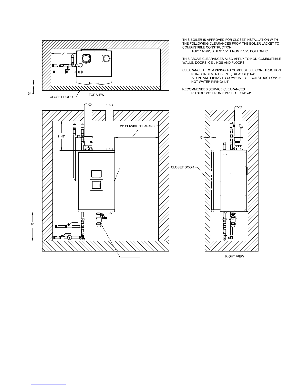
1. Observe the minimum clearances shown in Figure 4.1. These clearances apply to combustible construction as well as
non-combustible walls, oors, ceilings and doors.
2. Note the recommended service clearances in Figure 4.1. These service clearances are recommended, but may be reduced
to the combustible clearances provided:
a. Access to the front of the boiler is provided through a door.
b. Access is provided to the condensate trap located beneath the boiler.
Note that servicing the boiler will become increasingly difcult as these service clearances are reduced.
3. Observe the following clearances from piping to combustible construction:
Non-concentric vent (exhaust): ¼"
Air intake piping: 0"
Hot water piping: ¼"
4. The relief valve and gauge must be installed in the location shown in Figure 2.1 and must be in the same space as the
boiler.
5. The boiler should be located so as to minimize the length of the vent system.
6. The combustion air piping must terminate where outdoor air is available for combustion and away from areas that will
contaminate combustion air. Avoid areas near chemical products containing chlorine, chloride based salts, chloro/uoro
carbons, paint removers, cleaning solvents and detergents.
10
106375-01 - 4/16
IV. Locating the Boiler (continued)
1
"
2
FRONT VIEW
*RIGHT SIDE CLEARANCE MAY BE REDUCED TO 1/2"
HOWEVER RELIEF VALVE MUST REMAIN IN SAME
SPACE AS BOILER.
Figure 4.1: Minimum Clearances To Combustible Construction
SERVICE
ACCESS
PANEL
PROVIDE ACCESS TO THIS AREA
FOR INSPECTION AND CLEANOUT
OF CONDENSATE TRAP
106375-01 - 4/16
11

V. Mounting The Boiler
A. Wall Mounting
CAUTION
• Two people are required to safely lift this boiler onto the wall mounting hook.
• Make sure that wall mounting hook is anchored to a structure capable of supporting the
weight of the boiler and attached piping when lled with water. Jurisdictions in areas
subject to earthquakes may have special requirements for supporting this boiler. These
local requirements take precedence over the requirements shown below.
1. If the boiler is installed on a framed wall, minimum acceptable framing is 2 x 4 studs on 16" centers. The boiler
mounting holes are on 16" centers for installation between two studs at the standard spacing. In cases where the boiler
cannot be centered between the studs, or where the studs are spaced closer than 16" apart, the boiler may be anchored
to ¾" plywood or horizontal 2 x 4’s anchored to the studs.
2. 5/16" x 2" lag screws and washers are provided for mounting this boiler. These lag screws are intended for mounting
the boiler directly onto studs covered with ½" sheathing. When the boiler is attached to other types of construction,
such as masonry, use fasteners capable of supporting the weight of the boiler and attached piping in accordance with
good construction practice and applicable local codes.
3. Make sure that the surface to which the boiler is mounted is plumb.
4. Before mounting the boiler, make sure that wall selected does not have any framing or other construction that will
interfere with the vent pipe penetration.
5. Once a suitable location has been selected for the boiler, and any needed modications have been made to the wall, use
Figure 5.1 to locate holes “A” and “B”. Make sure that the horizontal centerline of these holes is level. Holes “C” and
“D” may also be drilled at this time or after the boiler is hung on the wall. If the 5/16" x 2" lag screws are used, drill
3/16" pilot holes.
6. The wall mounting hook is used to secure the boiler to the shipping pallet. Remove this hook from the pallet and
secure to the wall using the 5/16" x 2" lag screws and washers, or other suitable anchors as appropriate (Figure 5.2).
Make sure the hook is level.
7. Hang the boiler on the wall hook as shown in Figure 5.2.
8. If not already done in Step (5) locate and drill holes “C” and “D” using the obround slots in the bottom mounting
ange. Secure the bottom ange to the wall using the 5/16"x 2" lag screws, or other fasteners as appropriate (Figure
5.2).
9. Verify that the front of the boiler is plumb. If it is not, install washers at holes “C” and “D” between the bottom
mounting ange and the wall to adjust.
12
106375-01 - 4/16

Figure 5.1 Wall Layout / Mounting Hole Location
V. Mounting The Boiler (continued)
106375-01 - 4/16
13

Figure 5.2 Boiler Mounting Bracket Installation / Boiler Wall Mounting
V. Mounting The Boiler (continued)
14
106375-01 - 4/16

VI . Air for Ventilation
WARNING
Outdoor combustion air must be piped to the air intake. Never pipe combustion air from areas containing
contaminates such as swimming pools and laundry room exhaust vents. Contaminated combustion air will
damage the boiler and may cause property damage, personal injury or loss of life.
Air for combustion must always be obtained directly from outdoors. See Section VII “Venting” for intake piping.
Adequate air for ventilation will be present if the clearances specied in this manual are maintained. If this boiler is
installed in a room with other appliances, provide adequate air for combustion and/or ventilation air in accordance with the
manufacturer’s installation manual or applicable code.
106375-01 - 4/16
15

VII. Venting
WARNING
Asphyxiation Hazard. Failure to vent this boiler in accordance with these instructions could cause
products of combustion to enter the building resulting in severe property damage, personal injury or
death.
Do not interchange vent systems or materials unless otherwise specied.
The use of thermal insulation covering vent pipe and ttings is prohibited.
Do not use a barometric damper, draft hood or vent damper with this boiler.
When using the CPVC/PVC vent option, the use of CPVC is required when venting in vertical or
horizontal chase ways.
Do not locate vent termination where exposed to prevailing winds. Moisture and ice may form on
surface around vent termination. To prevent deterioration, surface must be in good repair (sealed,
painted, etc.).
Do not locate air intake vent termination where chlorines, chlorouorocarbons (CFC’s), petroleum
distillates, detergents, volatile vapors or other chemicals are present. Severe boiler corrosion and
failure will result.
The use of cellular core PVC (ASTM F891), cellular core CPVC or Radel (polyphenolsulfone) is
prohibited.
Do not locate vent termination under a deck.
Do not reduce specied diameters of vent and combustion air piping.
When installing vent pipe through chimney, as a chase, no other appliance can be vented into the
chimney.
Do not allow low spots in the vent where condensate may pool.
DANGER
Failure to follow this warning could result in asphyxiation and/or carbon monoxide poisoning. Correct
venting material and installation is required for proper vent operation. PVC Vent Systems must include at
least 30 inches of CPVC and one CPVC elbow between the boiler and PVC vent piping. See this Section, VII.
Venting for complete information.
A. Vent System Design
There are three basic ways to vent this boiler:
• Horizontal (“Side Wall”) Twin Pipe Venting (Figure 7.0a) - Vent system exits the building through an outside wall.
Combustion air and ue gas are routed between the boiler and the terminal(s) using separate pipes for at least part of the
way. A summary of Horizontal Twin Pipe venting options is shown in Table 7.5.
• Vertical Twin Pipe Venting (Figure 7.0b) - Vent system exits the building through a roof. Combustion air and ue gas
are routed between the boiler and the terminal(s) using separate pipes for at least part of the way. A summary of Vertical
Twin Pipe venting options is shown in Table 7.13
• Split Venting (Figure 7.0c) - Exhaust system exits the building through a roof, and combustion air is drawn from a
terminal mounted on the side wall. A summary of split venting options is shown in Table 7.21
All of these systems are considered “direct vent” because the air for combustion is drawn directly from the outdoors into the
boiler. One of the vent option columns in Tables 7.5, 7.13, 7.21 must match the planned vent and air intake system exactly.
Design details applying to all vent systems are shown in this section. Observe all design requirements in this section, as well as
those unique to the type of system being installed:
• B - Design Requirements Unique to Horizontal Twin Pipe Vent Systems
• C - Design Requirements Unique to Vertical Twin Pipe Vent Systems
• D - Design Requirements Unique to Split Vent Systems
16
106375-01 - 4/16

VII. Venting A. Vent System Design (continued)
Figure 7.0a: Horizontal Twin Pipe
106375-01 - 4/16
Figure 7.0b: Vertical Twin Pipe
Figure 7.0c: Split Venting
17

VII. Venting A. Vent System Design (continued)
1. Listed Vent Systems and Materials – The following materials and vent systems may be used to vent this boiler:
• CPVC – Use only CPVC listed to ASTM F441. In Canada, this pipe must also be listed to ULC S636.
• PVC – PVC may be used only as permitted in this manual. All PVC must be listed to ASTM D2665. At least 30" of
CPVC pipe, and at least one CPVC elbow, must be installed between the boiler’s vent connection and the PVC pipe. Use
of foam core PVC is not permitted for venting. PVC vent pipe may not be used to vent this boiler in Canada.
• DuraVent PolyPro - ULC S636 listed PolyPropylene special gas vent system.
• Selkirk Polyue - ULC S636 listed PolyPropylene special gas vent system.
• Centrotherm InnoFlue SW - ULC S636 listed PolyPropylene special gas vent system.
• Use PVC and/or CPVC for the air intake system. PVC may be used for all air intake piping between the intake terminal
and the boiler.
• When CPVC and/or PVC pipe is used, it must be joined using primer and cement that is listed for use with the pipe
material being joined (PVC, CPVC, or CPVC to PVC).
2. Maximum Vent and Air Intake Lengths - The maximum length of the vent air intake piping depends upon the vent option
selected and the boiler size. See Tables 7.5, 7.13 or 7.21 for the maximum vent lengths. These maximum lengths apply
to both the vent and intake piping (e.g. Option 1 may have up to 60ft of intake and 60ft of vent piping). For all vent
systems, the lengths shown in Tables 7.5, 7.13 and 7.21 are in addition to the rst 90° elbow. If more elbows are desired,
the maximum allowable vent length must be reduced by the amount shown in Table 7.1 for each additional elbow used.
Termination ttings are never counted.
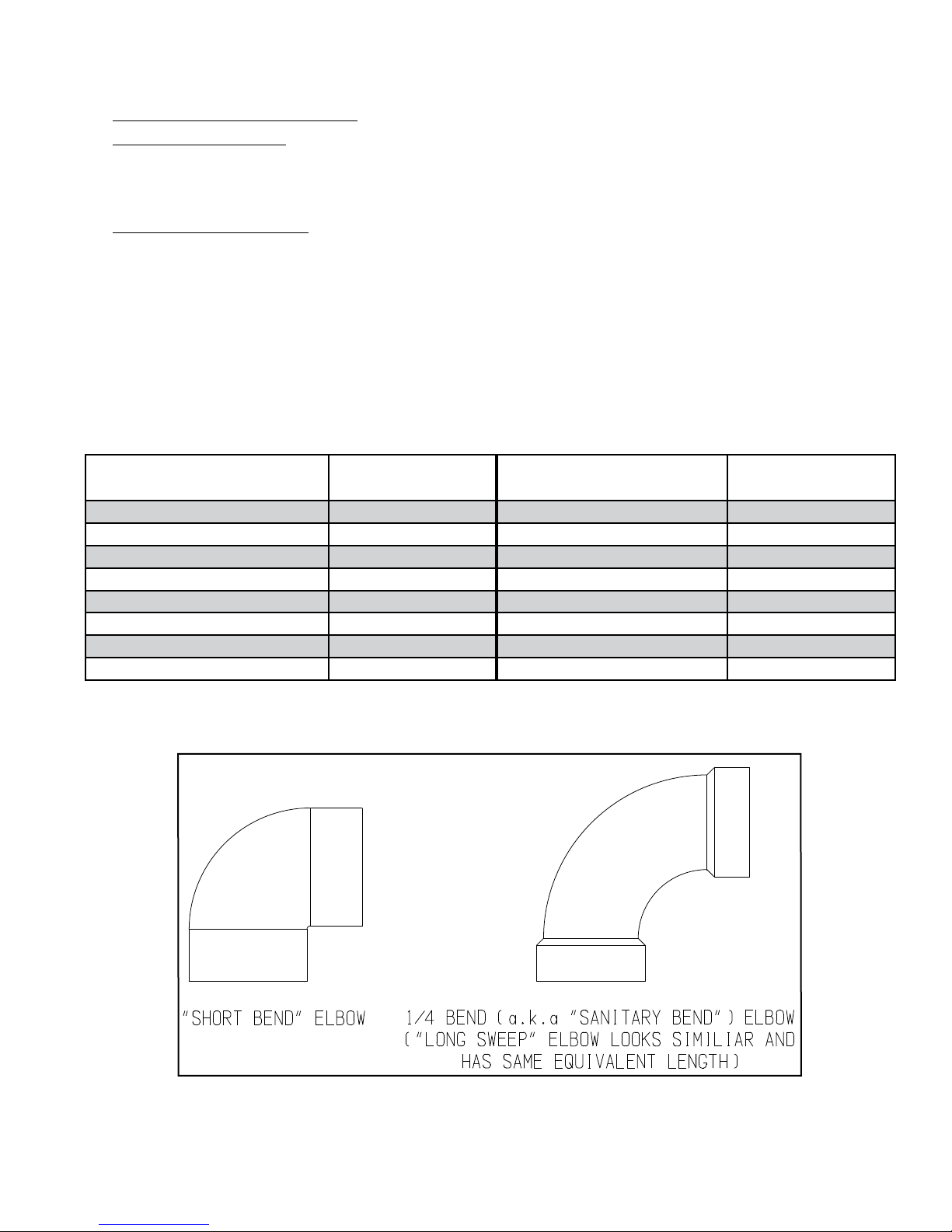
It is recommended that all eld supplied PVC or CPVC elbows be “1/4 Bend” (Sanitary 90° El) or “Long Sweep 1/4
Bend” type elbows (Figure 7.2). In this manual “sanitary” and “long sweep” elbows are treated as having the same equivalent
length.
Example:
A 3" twin pipe horizontal CPVC/PVC vent system is planned for a horizontally vented 155MBH model which has the
following components in the vent system:
• 1 ft CPVC Straight Pipe
• 90 CPVC Elbow (short bend)
• 1-1/2 ft CPVC Straight Pipe
• Coupling
• 10 ft PVC Straight Pipe
• 90 PVC Elbow (Sanitary Elbow Design)
• 15 ft PVC Straight Pipe
• PVC Coupling Terminal
The Vent Option #2 column in Table 7.5 describes a horizontal direct vent system using 3" CPVC and PVC pipe. From this
column,weseethattheboilermayhaveaventlengthofupto135ft.TherstCPVC90degreeelbowisnotconsidered.From
Table 7.1, we see that the equivalent length of the 90 PVC elbow is 4ft and that the equivalent length of the coupling is 0ft.
The total equivalent length of the planned venting system is therefore:
1ft(StraightCPVC)+0ft(rstshortbendCPVC90Elbow)+1.5ft(StraightCPVC)+0ft(Coupling)+10ft(StraightPVC)
+ 4ft (PVC 90 Sanitary Elbow) + 15ft (Straight PVC) + 0ft (Coupling Terminal) = 31.5ft.
Since Table 7.1 shows a maximum allowable vent length of 135ft, the planned vent system length is acceptable
The ex venting used on some of the Vertical Twin Pipe and Split Vent Options also reduces the maximum allowable vent
length. See Sections VII-C or VII-D for details.
NOTICE
Do not exceed maximum vent/combustion air system length. Refer to Tables 7.1 and 7.13 in this
section for maximum vent/combustion air system length.
Use only vent and combustion air terminals and terminal locations shown in Tables 7.5, 7.13, and
7.21 and related Figures in this section.
18
106375-01 - 4/16
VII. Venting A. Vent System Design (continued)
3. Minimum Vent and Air Intake Lengths - Observe the minimum vent lengths shown in Tables 7.5, 7.13 and 7.21.
4. Clearances to Combustibles - Maintain the following clearances from the vent system to combustible construction:
• Vent - 1/4" (also observe clearances through both combustible and non-combustible walls - see 9 below)
• Air Intake - 0"
• Concentric Portion of Concentric Terminals - 0"
5. Pitch of Horizontal Vent Piping - Pitch all horizontal vent piping so that any condensate which forms in the piping will run
towards the boiler.
• Pitch CPVC/PVC vent piping 1/4" per foot.
• Pitch PolyPropylene vent piping 5/8" per foot.
For Category I, II, and IV boilers, have horizontal runs sloping upwards not less than 1/4 inch per foot (21 mm/m) from the
boiler to the vent terminal.
Les chaudières de catégories I, II et IV doivent présenter des tronçons horizontaux dont la pente montante est d’au moins
5/8 po par pied (52 mm/m) entre la chaudière et l’évent.
Table 7.1: Vent/ Air Intake Fitting Equivalent Length
CPVC/PVC Fitting Equivalent Length (ft)
2" 90° Elbow (“Sanitary Bend”) 2.6 2" 90° Elbow 4.5
3" 90° Elbow (“Sanitary Bend”) 4.0 3" 90° Elbow 8.7
2" 90° Elbow (“Short Bend”) 6.0 2" 45° Elbow 2.5
3" 90° Elbow (“Short Bend”) 10.0 3" 45° Elbow 4.6
2" 45° Elbow 1.5
3" 45° Elbow 2.0
2" Coupling 0.0
3" Coupling 0.0
PolyPro, Polyue or InnoFlue
Vent Fitting
Equivalent Length (ft)
106375-01 - 4/16
Figure 7.2: CPVC and PVC Elbows
19

VII. Venting A. Vent System Design (continued)
7. Supporting Pipe - Vertical and horizontal sections of pipe must be properly supported. Maximum support spacing is as
follows:
• Support CPVC/PVC horizontally and vertically every 4 feet.
• Support DuraVent PolyPro horizontally near the female end of each straight section of pipe and vertically every 10 feet.
• Support Centrotherm InnoFlue horizontally every 39 inches with additional supports at elbows and vertically every 78".
• Support 2" Selkirk Polyue horizontally every 30". Support 3" Polyue horizontally every 39". Support vertical runs of
both 2" and 3" Polyue every 16 ft.
Les instructions d´installation du système d´évacuation doivent préciser que les sections horizontales doivent être
supportées pour prévenir le échissement. Les méthodes et les intervalles de support doivent être spéciés. Les
instructions divent aussi indiquer les renseignements suivants:
• les chaudières de catégories II et IV doivent être installées de façon à empêcher l´accumulation de condensat: et si
nécessaire, les chaudières de catégories II et IV doivent être pourvues de dispositifs d´évacuation du condensat.
8. Allowing for Thermal Expansion -
• For CPVC/PVC pipe design the vent system to allow 3/8" of thermal expansion for every 10ft of CPVC/PVC pipe.
The boiler will always act as an anchor to one end of the vent system. If at all possible, select and install hangers and
wall thimbles so that the vent system can expand towards the terminal. When a straight run of pipe exceeds 20ft and
must be restrained at both ends, an offset or expansion loop must be provided (Figures 7.3a, 7.3b). When a straight
horizontal run of pipe exceeds 20ft and is restrained at one end with an elbow at the other, avoid putting a hanger or
guide less than “Y” inches from the elbow in the adjoining straight section (Figure 7.3c). Thermal expansion ttings
are not permitted.
• When properly assembled expansion of PolyPro, Polyue and InnoFlue vent systems is accommodated at the joints. See
Part VII-F, G & H of this manual for details.
9. Running PVC Vent Pipe Inside Enclosures and Through Walls - PVC vent pipe must be installed in a manner that permits
adequate air circulation around the outside of the pipe:
• Do not enclose PVC venting - Use CPVC in enclosed spaces, even if PVC is installed upstream.
• PVC venting may not be used to penetrate combustible or non-combustible walls unless all of the following conditions are
met:
a. The wall penetration is at least 66 inches from the boiler as measured along the vent.
b. The wall is 12" thick or less
c. An airspace of at least that shown in Figure 7.4 is maintained around the OD of the vent.
If any of these conditions cannot be met, use CPVC for the wall penetration.
10. Vent Manufacturer’s Instructions – The vent system manufacturer may have additional vent system design requirements.
Read and follow the vent manufacturer’s instructions in addition to those shown here. Where a conict arises between the
two sets of instructions, the more restrictive requirements shall govern.
20
106375-01 - 4/16

VII. Venting A. Vent System Design (continued)
Figure 7.3bFigure 7.3a
Figure 7.3c
Figure 7.3: Expansion Loops for CPVC/PVC Pipe
Figure 7.4: Wall Penetration Clearances for PVC Vent Pipe
106375-01 - 4/16
21

VII. Venting B. Design Requirements Unique to Horizontal Twin Pipe Venting Systems (continued)
B. Design Requirements Unique to Horizontal Twin Pipe Venting Systems
Table 7.5 summarizes all horizontal twin pipe vent options. Illustrations of horizontal twin pipe vent systems are shown in
Figures 7.6 – 7.10. In addition to the requirements in Part VII-A, observe the following design requirements:
1. Permitted Terminals for Horizontal Venting:
Terminal Option A: Fittings (Acceptable for Vent Options 1-8) – Vent terminates in a plain end (coupling for PVC, bell
end for PolyPro, Polyue and plain end pipe for InnoFlue). Intake terminates in a PVC 90 sweep elbow pointing down.
Outer edge of both terminals must be within 10" of the wall surface (Figures 7.6, 7.9). The section of DuraVent PolyPro,
Centrotherm InnoFlue or Selkirk Polyue exposed to the outdoors must be UV resistant.
Use of rodent screens is generally recommended for both terminations. Two rodent screens suitable for 3" PVC terminals are
installed as shown in Figure 7.27. If 2" CPVC is used, these screens can be cut to t into the smaller ttings. Rodent screens
(“bird guards”) for PolyPro, InnoFlue and Polyue are as follows:
Size/Vent System Rodent Screen (“Bird Guard”)
2" PolyPro DuraVent # 2PPS-BG
3" PolyPro DuraVent # 3PPS-BG
2" Polyue Selkirk # 2PF-HVST
3" Polyue Selkirk # 3PV-HVST
2" InnoFlue Centrotherm # IASPP02
3" InnoFlue Centrotherm # IASPP03
If necessary to achieve required clearance above grade, CPVC or CPVC/PVC vent systems may be terminated using ttings
on snorkels as shown in Figure 7.12. When this is done, the equivalent length of all pipe on the exterior of the building,
except for the terminal ttings themselves, must be counted when calculating the equivalent length. The maximum vertical
run of the snorkel is 7 feet. Brace both the vent and inlet piping if required. PolyPro, InnoFlue and Polyue may not be
snorkeled.
Terminal Option B: Ipex Low Prole Terminal (Acceptable for Vent Options 1,2) – This terminal is shown in Figure 7.7. If
the terminal is oriented vertically (alternate orientation shown in Fig 7.7) the exhaust opening must be on the top as shown.
See Part VII-E of this manual and the Ipex instructions provided with the terminal, for installation details.
Terminal Option C: Diversitech “Low Prole” Terminal (Acceptable for Vent Options 1,2) – This terminal is shown in Figure
7.7. If the terminal is oriented vertically (alternate orientation shown in Fig 7.7) the exhaust opening must be on the top as
shown. See Part VII-E of this manual and the Diversitech instructions provided with the terminal, for installation details.
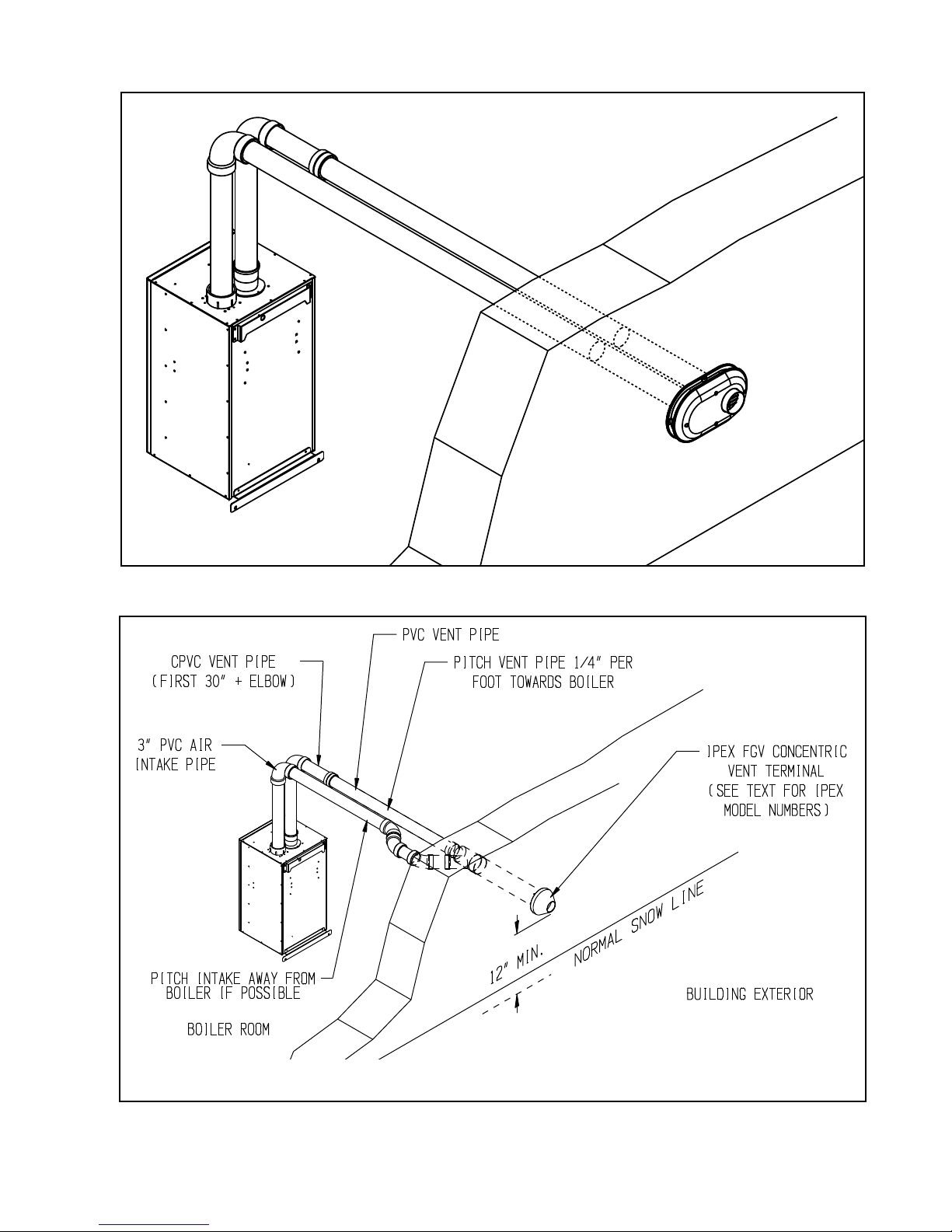
Terminal Option D: Ipex FGV Concentric Terminal (Acceptable for Vent Options 1,2) - This terminal is shown in Figure 7.8
and may be used with CPVC/PVC vent systems. This terminal is available in various lengths and in both PVC and CPVC.
Terminals acceptable for use with these vent options are as follows:
Ipex PN FGV Concentric Terminal Description
196005 2 x 16" PVC
196105 2 x 28" PVC
196125 2 x 40" PVC
196006 3 x 20" PVC
196106 3 x 32" PVC
196116 3 x 44" PVC
197107 3 x 32" CPVC
197117 3 x 44" CPVC
See Part VII-E of this manual and the Ipex instructions provided with the terminal, for installation details.
Terminal Option E: Diversitech Concentric Terminal (Acceptable for Vent Options 1,2) - This terminal is shown in Figure 7.8
and may be used with CPVC/PVC vent systems. See Part VII-E of this manual and the Diversitech instructions provided with
the terminal, for installation details.
Terminal Option F: DuraVent PolyPro Concentric Terminal (Acceptable for Vent Options 3,4) - This terminal is shown in
Figure 7.10 and may be used with DuraVent 2" or 3" PolyPro vent systems. See Part VII-F of this manual and the DuraVent
instructions provided with the terminal, for installation details.
22
106375-01 - 4/16

VII. Venting B. Design Requirements Unique to Horizontal Twin Pipe Venting Systems (continued)
Table 7.5: Summary of Horizontal Twin Pipe Venting Options
Vent Option 1 2 3 4 5 6 7 8
Illustrated in Figure
Pipe
Penetration
through
Structure
Material
Nominal
Diameter
Min Equivalent Vent Length:
Model Sizes
Max Equivalent Vent Length (Note 1):
Model Sizes
Terminal
Vent Wall Wall Wall Wall Wall Wall Wall Wall
Intake Wall Wall Wall Wall Wall Wall Wall Wall
Vent
Intake PVC PVC PVC PVC PVC PVC PVC PVC
Vent 2" 3" 2" 3" 2" 3" 2" 3"
Intake 2" 3" 2" 3" 2" 3" 2" 3"
85 30" 30" 30" 30" 30" 30" 30" 30"
110 30" 30" 30" 30" 30" 30" 30" 30"
155
205 30" 30" 30" 30"
270 30" 30" 30" 30"
85 60ft 135ft 60ft 135ft 60ft 135ft 60ft 135ft
110 60ft 135ft 60ft 135ft 60ft 135ft 60ft 135ft
155
205 135ft 135ft 135ft 135ft
270 135ft 135ft 135ft 135ft
Vent
Option A
(Fittings)
Intake
Terminal Option B
(Ipex Low Prole)
Terminal Option C
(Diversitech HVENT)
Terminal Option D
(Ipex FGV Concentric)
Terminal Option E
(Diversitech CVENT)
Terminal Option F
(DuraVent Horizontal
Concentric)
7.6, 7.7,
7.8
CPVC/
PVC
(Note 2)
Not
Permitted
Not
Permitted
Coupling
w/screen
(Note 3)
Elbow
w/screen
(Note 3)
Ipex #
196984
HVENT-2 HVENT-3
Ipex
196105
CVENT-2 CVENT-3
Not
Permitted
7.6, 7.7,
7.8
CPVC/
PVC
(Note 2)
30"
135ft
Coupling
w/screen
(Note 3)
Elbow
w/screen
(Note 3)
Ipex
#196985
Ipex
196006
Not
Permitted
7.9, 7.10 7.9, 7.10 7.9 7.9 7.9 7.9
DuraVent
PolyPro
(Rigid)
Not
Permitted
Not
Permitted
2PPS-12B
or
2PPS-36B
w/screen
Elbow
w/screen
Not
Permitted
Not
Permitted
Not
Permitted
Not
Permitted
2PPS-HK 3PPS-HK
DuraVent
PolyPro
(Rigid)
30"
135ft
3PPS-12B
or
3PPS-36B
w/screen
Elbow
w/screen
Not
Permitted
Not
Permitted
Not
Permitted
Not
Permitted
Selkirk
Polyue
Not
Permitted
Not
Permitted
2PF-10UV
or
2PF-39UV
w/screen
Elbow
w/screen
Not
Permitted
Not
Permitted
Not
Permitted
Not
Permitted
Not
Permitted
Selkirk
Polyue
30"
135ft
3PF-10UV
or
3PF-39UV
w/screen
Elbow
w/screen
Not
Permitted
Not
Permitted
Not
Permitted
Not
Permitted
Not
Permitted
Centro-
therm
InnoFlue
SW
Not
Permitted
Not
Permitted
ISEP02 or
ISEP0239
w/screen
Elbow
w/screen
Not
Permitted
Not
Permitted
Not
Permitted
Not
Permitted
Not
Permitted
Centro-
InnoFlue
ISEP03 or
ISEP0339
w/screen
Elbow
w/screen
Permitted
Permitted
Permitted
Permitted
Permitted
therm
SW
30"
135ft
Not
Not
Not
Not
Not
Notes:
1. Max vent lengths shown also apply to the intake. For example, Vent Option #1 may have up to 60ft of vent pipe and also up to
60 ft of intake pipe.
2. At least 30" of CPVC pipe, and at least one CPVC elbow, must be installed between the boiler's vent connection and PVC pipe.
Downstream vent pipe can be PVC except as noted in text.
3. PVC Terminal coupling and inlet elbow may be offset on snorkels as shown in Figure 7.12.
106375-01 - 4/16
23

VII. Venting B. Design Requirements Unique to Horizontal Twin Pipe Venting Systems (continued)
2. Horizontal Vent and Air Intake Terminal Location - Observe the following limitations on the vent terminal location (also see
Figure 7.11). When locating a concentric terminal, observe the limitations outlined below for “vent terminals”.
• Vent terminal must be at least 1 foot from any door, window, or gravity inlet into the building.
• When Terminal Option A (ttings) are used, maintain the correct clearance and orientation between the intake
and exhaust terminals. If possible, locate vent and combustion air terminals on the same wall to prevent nuisance
shutdowns. If not, boiler may be installed with roof vent terminal and sidewall combustion air terminal (see Paragraph
D). When installed on the same wall, locate exhaust vent terminal at same height or higher than combustion air
intake terminal. Horizontal separation: Recommended: 36", Minimum: 12", Maximum: none. Minimum horizontal
separation of 12" is required regardless of vertical separation.
• The bottom of all terminals must be at least 12" above the normal snow line. In no case should they be less than 12"
above grade level.
• The bottom of the vent terminal must be at least 7 feet above a public walkway.
• Do not install the vent terminal directly over windows or doors.
• The bottom of the vent terminal must be at least 3 feet above any forced air inlet located within 10 feet.
• USA Only: A clearance of at least 4 feet horizontally must be maintained between the vent terminal and gas meters,
electric meters, regulators, and relief equipment. Do not install vent terminal over this equipment. In Canada, refer to
B149.1 Installation Code for clearance to meters, regulators and relief equipment.
• Do not locate the vent terminal under decks or similar structures.
• Top of terminal must be at least 24" below ventilated eves, softs and other overhangs. In no case may the overhang
depth exceed 48". Where permitted by the authority having jurisdiction and local experience, the terminal may be
located closer to unventilated softs. For the minimum vertical separation which depends upon the depth of the soft,
see Figure 7.11.
• Vent terminal must be at least 6 feet from an inside corner.
• Under certain conditions, water in the ue gas may condense, and possibly freeze, on objects around the vent terminal
including on the structure itself. If these objects are subject to damage by ue gas condensate, they should be moved or
protected.
• Install the vent and air intake terminals on a wall away from the prevailing wind. Reliable operation of this boiler
cannot be guaranteed if these terminals are subjected to winds in excess of 40 mph.
• Air intake terminal must not terminate in areas that might contain combustion air contaminates, such as near
swimming pools. See WARNING on page 15.
CPVC VENT PIPE
(FIRST 30" + ELBOW)
PVC AIR
INTAKE PIPE
BOILER ROOM
PITCH INTAKE AWAY FROM
BOILER IF POSSIBLE
RECOMMEND EXHAUST MIN.
12" ABOVE INTAKE. MAY
REDUCE TO 0" IF NEEDED.
PVC VENT PIPE
PITCH VENT PIPE
FOOT TOWARDS BOILER
TRIM
COLLAR
1
" PER
4
EXHAUST TERMINAL
WITH RODENT SCREEN
INLET TERMINAL WITH
RODENT SCREEN
TRIM PLATE - PROVIDE
FOR EXPANSION AND
CLEARANCE THROUGH
WALL AS NEEDED
ALTERNATE INLET
TERMINAL LOCATION
BUILDING EXTERIOR
Figure 7.6: Horizontal CPVC/PVC Venting, (Vent Options #1 & 2, Terminal Option A)
24
106375-01 - 4/16
VII. Venting B. Design Requirements Unique to Horizontal Twin Pipe Venting Systems (continued)
Figure 7.7: Horizontal CPVC/PVC Venting with Low Prole Terminal,
(Vent Options #1 & 2, Terminal Options B & C)
Figure 7.8: Horizontal CPVC/PVC Venting with Concentric Vent Terminal,
(Vent Options #1 & 2, Terminal Options D & E)
106375-01 - 4/16
25

VII. Venting B. Design Requirements Unique to Horizontal Twin Pipe Venting Systems (continued)
Figure 7.9: Duravent PolyPro, Selkirk, Polyue or Centrotherm InnoFlue Horizontal Venting
(Vent Option #3 - 8, Terminal Option A)
Figure 7.10: Duravent PolyPro Horizontal Venting with Concentric Terminal,
(Vent Options #3 & 4, Terminal Option F)
26
106375-01 - 4/16

VII. Venting B. Design Requirements Unique to Horizontal Twin Pipe Venting Systems (continued)
106375-01 - 4/16
Terminal (Shown) Two-Pipe System Air Intake Terminal (Not Shown)
Note: Air intake termination not shown, refer to
Venting Section in Installation Instructions
supplied with the boiler.
Figure 7.11: Location of Vent Terminal Relative to Windows, Doors, Grades, Overhangs, Meters and Forced Air Inlets - Two-Pipe System Vent
27

VII. Venting C. Design Requirements Unique to Vertical Venting Systems (continued)
Figure 7.12: Snorkel Terminal Conguration (CPVC/PVC Vent Systems Only)
C. Design Requirements Unique to Vertical Venting Systems
Table 7.13a summarizes all vertical twin pipe vent options. Table 7.13.b summarizes vent options in which an abandoned
B-vent chimney is used both as a chase for the vent pipe and as a conduit for combustion air.
In addition to the requirements in Part VII-A, observe the following design requirements:
1. Permitted Terminals for Vertical Venting
Terminal Option H: Fittings (Acceptable for Vent Options 10-17) – Vent terminates in a plain end (coupling for PVC, bell
end for PolyPro, Polyue and plain end pipe for InnoFlue). Intake terminates in a PVC 180 elbow pointing down (two sweep
90’s may be substituted). Observe the clearances from the roof, and normal snow line on the roof, shown in Figures 7.15 and
7.17. The section of PolyPro, Polyue or InnoFlue exposed to the outdoors must be UV resistant.
Use of rodent screens is generally recommended for both terminations. Two rodent screens suitable for 3" PVC terminals
are installed as shown in Figure 7.28. If 2" CPVC is used, these screens can be cut to t into the smaller ttings. Rodent
screens (“bird guards”) for PolyPro, Polyue and InnoFlue are as follows:
Size/Vent System Rodent Screen (“Bird Guard”)
2" PolyPro DuraVent # 2PPS-BG
3" PolyPro DuraVent # 3PPS-BG
2" Polyue Selkirk # 2PF-HVST
3" Polyue Selkirk # 3PV-HVST
2" InnoFlue Centrotherm # IASPP02
3" InnoFlue Centrotherm # IASPP03
Terminal Option I: Ipex FGV Concentric Terminal (Acceptable for Vent Options 10 & 11) - This terminal is shown in Figure
7.16 and may be used with CPVC/PVC vent systems. Use a compatible roof ashing and storm collar in accordance with
the Ipex instructions for this terminal. This terminal is available in various lengths and in both PVC and CPVC. Terminals
acceptable for use with these vent options are as follows:
Ipex PN FGV Concentric Terminal Description
196005 2 x 16" PVC
196105 2 x 28" PVC
196125 2 x 40" PVC
196006 3 x 20" PVC
196106 3 x 32" PVC
196116 3 x 44" PVC
197107 3 x 32" CPVC
197117 3 x 44" CPVC
See Part VII-E of this manual and the Ipex instructions provided with the terminal, for installation details.
28
106375-01 - 4/16

VII. Venting
C. Design Requirements Unique to Vertical Venting Systems (continued)
Table 7.13a: Summary of Vertical Twin Pipe Venting Options
Option 10 11 12 13 14 15 16 17
Illustrated in Figure 7.15, 717 7.15, 7.17 7.17, 7.18 7.17, 7.18 7.17 7.17 7.17 7.17
Pipe
Penetration
through
Structure
Material
Nominal
Diameter
Min Equivalent Vent Length:
Model Sizes
Max Equivalent Vent Length (Note 1):
Model Sizes
Vent Roof Roof Roof Roof Roof Roof Roof Roof
Intake Roof Roof Roof Roof Roof Roof Roof Roof
CPVC/
Vent
Intake PVC PVC PVC PVC PVC PVC PVC PVC
Vent 2" 3" 2" 3" 2" 3" 2" 3"
Intake 2" 3" 2" 3" 2" 3" 2" 3"
85
110
155
205
270
85
110
155
205
270
PVC
(Note 2)
30" 30" 30" 30" 30" 30" 30" 30"
30" 30" 30" 30" 30" 30" 30" 30"
Not
Permitted
60ft 135ft 60ft 135ft 60ft 135ft 60ft 135ft
60ft 135ft 60ft 135ft 60ft 135ft 60ft 135ft
Not
Permitted
CPVC/
PVC
(Note 2)
30"
30" 30" 30" 30"
30" 30" 30" 30"
135ft
135ft 135ft 135ft 135ft
135ft 135ft 135ft 135ft
DuraVent
PolyPro
(Rigid)
Not
Permitted
Not
Permitted
DuraVent
PolyPro
(Rigid)
30"
135ft
Selkirk
Polyue
Not
Permitted
Not
Permitted
Selkirk
Polyue
30"
135ft
Centro-
therm
InnoFlue
SW
Not
Permitted
Not
Permitted
Centro-
therm
InnoFlue
SW
30"
135ft
2PPS-12B
Vent
Terminal Option H
(Fittings)
Intake
Terminal Option I
(Ipex FGV Concentric)
Coupling
w/Screen
180 Elbow
w/Screen
Ipex
196105
(Note 3)
Terminal Option J
(Diversitech CVENT
Concentric)
Terminal Option K
(DuraVent Vertical
Concentric)
Notes:
1. Max vent lengths shown also apply to the intake. For example, Vent Option #1 may have up to 60ft of vent pipe and also up to 60 ft of
intake pipe.
2. At least 30" of CPVC pipe, and at least one CPVC elbow, must be installed between the boiler's vent connection and PVC pipe.
Downstream vent pipe can be PVC except as noted in text.
3. Ipex FGV Concentric Terminal available in various lengths and also CPVC (see text).
CVENT-2 CVENT-3
Not
Permitted
Coupling
w/Screen
180 Elbow
w/Screen
Ipex
196006
(Note 3)
Not
Permitted
or
2PPS-36B
w/Screen
180 Elbow
w/Screen
Not
Permitted
Not
Permitted
2PPS-VK 3PPS-VK
3PPS-12B
or
3PPS-36B
w/Screen
180 Elbow
w/Screen
Not
Permitted
Not
Permitted
2PF-10UV
or
2PF-39UV
w/Screen
180 Elbow
w/Screen
Not
Permitted
Not
Permitted
Not
Permitted
3PF-10UV
or
3PF-39UV
w/Screen
180 Elbow
w/Screen
Not
Permitted
Not
Permitted
Not
Permitted
ISEP02 or
ISEP0239
w/Screen
180 Elbow
w/Screen
Not
Permitted
Not
Permitted
Not
Permitted
ISEP03 or
ISEP0339
w/Screen
180 Elbow
w/Screen
Not
Permitted
Not
Permitted
Not
Permitted
All vertical terminals require compatible roof ashing and storm collars.
106375-01 - 4/16
29

VII. Venting C. Design Requirements Unique to Vertical Venting Systems (continued)
Table 7.13b: Summary of Vertical “B-Vent Air Chase” Vent Options
(B-Vent Chase MUST Be Sealed)
Option 18 19 20 21
Illustrated in Figure 7.19 7.19 7.20 7.20
Pipe Penetration
Through Structure
Material
Nominal Diameter
Min Equivalent Vent Length:
Model Sizes
Max Equivalent Vent Length (Note 1):
Model Sizes
Vent Manufacturer’s PN for Flex
Termination/Components Required
Vent Roof Roof Roof Roof
Intake Roof Roof Roof Roof
Vent
Intake B Vent/PVC B Vent/PVC B Vent/PVC B Vent/PVC
Vent 2" 3" 2" 3"
Intake 2" or 3" 3" 2" or 3" 3"
Min B Vent ID 5" 6" 5" 6"
85 30" 30" 30" 30"
110 30" 30" 30" 30"
155
205 30" 30"
270 30" 30"
85 60ft 135ft 60ft 135ft
110 60ft 135ft 60ft 135ft
155
205 135ft 135ft
270 135ft 135ft
DuraVent
PolyPro (Rigid/
Flex)
Not Permitted
Not Permitted
2PPS-VFT
2PPS-BV*
2PPS-FLEX**
DuraVent
PolyPro (Rigid/
Flex)
30"
135ft
3PPS-VFT
3PPS-BV*
3PPS-FLEX**
Centrotherm
InnoFlue SW/
Flex
Not Permitted
Not Permitted
IFBK02****
IAWP02B
Centrotherm
InnoFlue
SW/Flex
30"
135ft
IFBK03****
IAWP03B
* Specify size of B vent (e.g. 2PPS-BV6 is for use with 6" B vent)
** Specify length in feet.
**** Specify Flex length and B-vent diameter (e.g. IFBK022505 includes 25ft of ex and used with 5" B vent)
Note 1: Max vent lengths shown also apply to the intake. Flex vent reduces the maximum allowable vent length.
See equivalent lengths for ex vent shown in Table 7.14 and sizing example on page 32.
Vertical venting and combustion air roof penetrations (where applicable) require the use of roof ashing
and storm collar, which are not supplied with the boiler, to prevent moisture from entering the structure.
30
NOTICE
106375-01 - 4/16
 Loading...