


U.S. Boiler Company 209E, 204E, 202E, 205E, 206E User Manual
...Installation, Operating and Service Instructions for |
• Chimney Vent |
||
SERIES 2 |
® |
||
|
|
• Water Boiler |
|
|
|
|
• Cast Iron |
Models: |
|
|
• Gas Fired |
|
|
|
|
• 202E |
|
|
|
• 203E |
|
|
|
• 204E |
|
|
|
• 205E |
|
|
|
• 206E |
|
|
|
• 207E |
|
|
|
• 208E |
|
|
|
• 209E |
|
|
|
Manual Contents |
Page |
|
|
Specifications . . . . . . . . . . . . . . . . . . . . . . . . |
. . . 3 |
|
|
Pre-installation. . . . . . . . . . . . . . . . . . . . . . . . . . |
4 |
|
|
Removing Existing Boiler. . . . . . . . . . . . . . . . . |
5 |
|
|
Clearances.. . . . . . . . . . . . . . . . . . . . . . . . . . . . |
. 5 |
|
|
Venting. . . . . . . . . . . . . . . . . . . . . . . . . . . . . . . |
. . 7 |
|
|
Water Piping. . . . . . . . . . . . . . . . . . . . . . . . . . . |
10 |
|
|
Gas Piping. . . . . . . . . . . . . . . . . . . . . . . . . . . . |
. 13 |
|
|
Electrical. . . . . . . . . . . . . . . . . . . . . . . . . . . . . . |
14 |
|
|
System Start-Up and Checkout . . . . . . . . . . . |
. 17 |
|
|
Operation. . . . . . . . . . . . . . . . . . . . . . . . . . . . . |
. 21 |
|
|
Before Leaving Jobsite.. . . . . . . . . . . . . . . . . . |
25 |
|
|
Service and Maintenance . . . . . . . . . . . . . . . . |
26 |
|
|
How It Works . . . . . . . . . . . . . . . . . . . . . . . . . . |
. 30 |
|
|
Troubleshooting. . . . . . . . . . . . . . . . . . . . . . . . |
32 |
|
|
Service Parts. . . . . . . . . . . . . . . . . . . . . . . . . . |
. 37 |
|
|
Appendix . . . . . . . . . . . . . . . . . . . . . . . . . . . . . |
. 44 |
|
|
TO THE INSTALLER: |
|
|
|
Affix these instructions adjacent to boiler. |
|
|
|
Provide model number and serial number when |
|
9700609 |
|
seeking information and support. |
|
|
|
TO THE CONSUMER:
Retain these instructions for future reference.
Contact heating contractor for all issues and support.
!WARNING
Improper installation, adjustment, alteration, service or maintenance can cause property damage, injury, or loss of life. For assistance or additional information, consult a qualified installer, service agency or the gas supplier. Read these instructions carefully before installing.
109443-01 - 6/19

SERIES 2E Installation, Operating & Service Manual
The City of New York requires a Licensed Master Plumber supervise the installation of this product.
The Massachusetts Board of Plumbers and Gas Fitters has listed the Series 2E® Boiler. See the Massachusetts Board of Plumbers and Gas Fitters website, http://license..reg..state..ma..us/pubLic/pl_products/pb_product..asp for the latest Approval Code or ask your local Sales Representative.
The Commonwealth of Massachusetts requires this product to be installed by a licensed Plumber or Gas fitter.
The following terms are used throughout this manual to bring attention to the presence of hazards of various risk levels, or to important information concerning product life..
! DANGER |
|
! CAUTION |
Indicates a hazardous situation that, if not avoided, will result in death or serious injury.
! WARNING
Indicates a hazardous situation that, if not avoided, could result in death or serious injury.
Indicates a hazardous situation that, if not avoided, could result in minor or moderate injury.
NOTICE: Indicates special instructions on installation, operation, or service which are important but not related to personal injury hazards.
! DANGER
Explosion Hazard.. DO NOT store or use gasoline or other flammable vapors or liquids in the vicinity of this or any other appliance.
If you smell gas vapors, DO NOT try to operate any appliance - DO NOT touch any electrical switch or use any phone in the building. Immediately, call the gas supplier from a remotely located phone. Follow the gas supplier’s instructions or if the supplier is unavailable, contact the fire department.
! WARNING
This boiler must only be serviced and repaired by skilled and experienced service technicians..
•If any controls are replaced, they must be replaced with identical models.
•Read, understand and follow all the instructions and warnings contained in all the sections of this manual.
•If any electrical wires are disconnected during service, clearly label the wires and assure that the wires are reconnected properly.
•Never jump out or bypass any safety or operating control or component of this boiler.
•Assure that all safety and operating controls and components are operating properly before placing the boiler back in service.
•Annually inspect all vent gaskets and replace any exhibiting damage or deterioration.
2 |
109443-01 - 6/19 |

SERIES 2E Installation, Operating & Service Manual
1 Specifications
Table 1A: Ratings
Boiler Model Number |
Input1 (MBH) |
DOE Heating Capacity (MBH) |
AHRI Net Rating2 (MBH) |
AFUE |
202E |
38 |
32 |
28 |
84.0 |
|
|
|
|
|
203E |
69 |
58 |
50 |
84.0 |
|
|
|
|
|
204E |
103 |
87 |
76 |
84.0 |
205E |
138 |
116 |
101 |
84.0 |
|
|
|
|
|
206E |
172 |
145 |
126 |
84.0 |
|
|
|
|
|
207E |
207 |
174 |
151 |
84.0 |
|
|
|
|
|
208E |
241 |
202 |
176 |
84.0 |
|
|
|
|
|
209E |
276 |
232 |
202 |
84.0 |
1Input ratings can be used for elevations up to 2,000 ft. Refer to Appendix: "High Altitude Installations" for installations above 2,000 ft.
2The Net AHRI Water Ratings shown are based on a piping and pickup allowance of 1.15. The manufacturer should be consulted before selecting a boiler for installations having unusual piping and pickup requirements, such as intermittent operation, extensive piping systems, etc.
Table 1B: Dimensions and Connections
|
|
|
|
|
|
|
|
|
|
|
|
|
|
|
|
|
|
|
|
|
|
|
Maximum |
|
Boiler |
No. of |
|
Depth |
Width |
|
Height |
|
|
|
Return |
|
Vent |
|
Gas |
|
Relief |
Drain |
Allowable |
|
|||||
Model |
|
|
|
Supply NPT |
|
|
|
Working |
|
|||||||||||||||
Number |
Sections |
|
(in) |
|
(in) |
|
(in) |
|
|
|
NPT |
|
(in) |
|
NPT |
|
Valve NPT |
NPT |
Pressure |
|
||||
|
|
|
|
|
|
|
|
|
|
|
|
|
|
|
|
|
|
|
|
|
|
|
||
|
|
|
|
|
|
|
|
|
|
|
|
|
|
|
|
|
|
|
|
|
|
|
(PSI) |
|
202E |
2 |
27 |
|
14 |
|
32 |
|
|
1-1/4 |
|
1-1/4 |
|
|
3 |
|
1/2 |
|
3/4 |
|
3/4 |
50 |
|
||
|
|
|
|
|
|
|
|
|
|
|
|
|
|
|
|
|
|
|
|
|
|
|
|
|
203E |
3 |
27 |
|
14 |
|
32 |
|
|
1-1/4 |
|
1-1/4 |
|
|
4 |
|
1/2 |
|
3/4 |
|
3/4 |
50 |
|
||
204E |
4 |
27 |
|
16 |
|
32 |
|
|
1-1/4 |
|
1-1/4 |
|
|
5 |
|
1/2 |
|
3/4 |
|
3/4 |
50 |
|
||
205E |
5 |
27 |
|
19 |
|
32 |
|
|
1-1/4 |
|
1-1/4 |
|
|
6 |
|
1/2 |
|
3/4 |
|
3/4 |
50 |
|
||
|
|
|
|
|
|
|
|
|
|
|
|
|
|
|
|
|
|
|
|
|
|
|
|
|
206E |
6 |
27 |
|
22 |
|
32 |
|
|
1-1/4 |
|
1-1/4 |
|
|
6 |
|
1/2 |
|
3/4 |
|
3/4 |
50 |
|
||
|
|
|
|
|
|
|
|
|
|
|
|
|
|
|
|
|
|
|
|
|
|
|
|
|
207E |
7 |
27 |
|
25 |
|
32 |
|
|
1-1/4 |
|
1-1/4 |
|
|
7 |
|
3/4 |
|
3/4 |
|
3/4 |
50 |
|
||
|
|
|
|
|
|
|
|
|
|
|
|
|
|
|
|
|
|
|
|
|
|
|
|
|
208E |
8 |
27 |
|
28 |
|
32 |
|
|
1-1/4 |
|
1-1/4 |
|
|
7 |
|
3/4 |
|
3/4 |
|
3/4 |
50 |
|
||
|
|
|
|
|
|
|
|
|
|
|
|
|
|
|
|
|
|
|
|
|
|
|
|
|
209E |
9 |
27 |
|
31 |
|
32 |
|
|
1-1/4 |
|
1-1/4 |
|
|
8 |
|
3/4 |
|
3/4 |
|
3/4 |
50 |
|
||
Table 1C: Weights and Volume |
|
|
|
|
|
|
|
|
|
|
|
|
|
|
|
|
|
|
|
|
||||
|
|
|
|
|
|
|
|
|
|
|
|
|
|
|
|
|
|
|
|
|
|
|
|
|
Boiler |
Shipping |
|
Empty |
|
Shipping |
|
Shipping |
Shipping |
|
|
Water |
|
Heat |
|
|
|
|
|||||||
|
|
|
|
|
Exchanger |
|
|
|
|
|||||||||||||||
Model |
Weight |
|
Weight |
|
Crate D |
|
Crate W |
Crate H |
|
Content |
|
|
|
|
||||||||||
|
|
|
|
Surface Area |
|
|
|
|
||||||||||||||||
Number |
(lbs) |
|
(lbs) |
|
|
(in) |
|
|
(in) |
|
(in) |
|
|
(gal) |
|
|
ft2 |
|
|
|
|
|||
|
|
|
|
|
|
|
|
|
|
|
|
|
|
|
|
|
|
|
|
|
|
|
|
|
202E |
202 |
|
143 |
|
|
|
46 |
|
26 |
39 1/2 |
|
1 |
|
|
3.86 |
|
|
|
|
|||||
203E |
241 |
|
182 |
|
|
|
46 |
|
26 |
39 1/2 |
|
2 |
|
|
7.72 |
|
|
|
|
|||||
204E |
292 |
|
230 |
|
|
|
46 |
|
26 |
39 1/2 |
|
3 |
|
|
11.58 |
|
|
|
|
|||||
|
|
|
|
|
|
|
|
|
|
|
|
|
|
|
|
|
|
|
|
|||||
205E |
341 |
|
279 |
|
|
|
46 |
|
26 |
39 1/2 |
|
4 |
|
|
15.44 |
|
|
|
|
|||||
|
|
|
|
|
|
|
|
|
|
|
|
|
|
|
|
|
|
|
|
|||||
206E |
390 |
|
328 |
|
|
|
46 |
|
26 |
39 1/2 |
|
5 |
|
|
19.31 |
|
|
|
|
|||||
|
|
|
|
|
|
|
|
|
|
|
|
|
|
|
|
|
|
|
||||||
207E |
449 |
|
378 |
|
|
51 1/2 |
|
35 |
39 1/2 |
|
6 |
|
|
23.17 |
|
|
|
|
||||||
208E |
502 |
|
431 |
|
|
51 1/2 |
|
35 |
39 1/2 |
|
7 |
|
|
27.03 |
|
|
|
|
||||||
209E |
548 |
|
476 |
|
|
51 1/2 |
|
35 |
39 1/2 |
|
8 |
|
|
30.81 |
|
|
|
|
||||||
Electrical Requirements: 120 VAC, 60 HZ, 1-ph, less than 12A |
|
|
|
|
|
|
|
|
|
|
||||||||||||||
|
|
|
|
|
|
|
|
|
|
|
|
|
|
|
|
|
|
|
|
|
|
|
|
|
109443-01 - 6/19 |
|
|
|
|
|
|
|
|
|
|
|
|
|
|
|
|
|
|
|
|
|
3 |
||

SERIES 2E Installation, Operating & Service Manual
2 Pre-installation
! WARNING
Carefully read all instructions before installing boiler. Failure to follow all instructions in proper order can cause personal injury or death.
A.Series 2E boiler is Category I, draft hood equipped appliance with vent damper.
B.Inspect shipment carefully for signs of damage. Any claim for damage or shortage in shipment must be filed immediately against carrier by consignee. No claims for variances or shortages will be allowed by Boiler Manufacturer, unless presented within sixty (60) days after receipt of equipment.
C.Installation must conform to requirements of authority having jurisdiction. In absence of such requirements, installation must conform to
National Fuel Gas Code, ANSI Z223.1/NFPA 54.
D.Appliance is design listed for installation on combustible flooring and must not be installed on carpeting.
E.Provide clearance between boiler jacket and combustible material in accordance with authority having jurisdiction. Minimum clearances outlined in Figure 4-1 (Closet Installations) or Figure 4-2 (Alcove Installations).
F.Provide practical service clearances. Minimum 24" from left side and front jacket panels is recommended for servicing.
G.Install on level floor. For basement installation provide concrete base if floor is not level or if water may be encountered on floor around boiler.
H.Protect gas ignition system components from water (dripping, spraying, rain, etc.) during boiler operation and service (circulator replacement, condensate trap, control replacement, etc.).
I.Provide combustion and ventilation air in accordance with the section "Air for Combustion and Ventilation," of the National Fuel Gas Code, ANSI Z223.1/NFPA 54, or applicable provisions of local building codes.
!WARNING
Adequate combustion and ventilation air must be provided to assure proper combustion and dilution air.
J.Do not install boiler where gasoline or other flammable vapors or liquids are stored. Avoid areas near chemical products containing chlorine, chloride based salts, chloro/fluorocarbons, paint removers, cleaning solvent, and detergents.
K.Consider using boiler bypass described in Section 6 "Water Piping" for systems which have a large volume or excessive radiation where low boiler water temperatures may be encountered.
L.Where required by authority having jurisdiction, installation must conform to standard for Controls and Safety Devices for Automatically Fired Boilers, ANSI/ASME CSD-1.
M.A hot water boiler installed above radiation level or as required by the authority having jurisdiction must be provided with a low water cutoff device. The IDL 1200 LWCO is supplied with boiler.
N.Boilers are shipped from factory configured for Natural Gas installations 0, 2,000 ft. For LP installations or high altitude installations, a conversion kit is required.
O.See Appendix: "High Altitude Installation" for installations above 2,000 ft.
Conversion Kits |
202E |
203E |
204E |
205E |
206E |
207E |
208E |
209E |
|
|
|
|
|
|
|
|
|
Natural Gas to LP (0-2,000 ft) |
109729-01 |
|
109706-01 |
|
|
109706-02 |
|
|
LP to Natural Gas (0-2,000 ft) |
109728-01 |
|
109705-01 |
|
|
109705-02 |
|
|
Components Shipped with Boiler:
Draft hood
Vent damper
Circulator
Miscellaneous parts bag (Supply water manifold, Temperature/pressure gauge, 30 psi safety relief valve, drain valve, circulator flanges)
4 |
109443-01 - 6/19 |

SERIES 2E Installation, Operating & Service Manual
3 Removing Existing Boiler
A.If an Existing Boiler is Removed:
When an existing boiler is removed from a common venting system, the common venting system is likely to be too large for proper venting of the appliances remaining connected to it.
At the time of removal of an existing boiler, the following steps shall be followed with each appliance remaining connected to the common venting system placed in operation, while the other appliances remaining connected to the common venting system are not in operation:
1.Seal any unused openings in the common venting system.
2.Visually inspect the venting system for proper size and horizontal pitch and determine there is no blockage or restriction, leakage, corrosion, and other deficiencies which could cause an unsafe condition.
3.Insofar as is practical, close all building doors and windows and all doors between the space in which the appliances remaining connected to the common venting system are located and other spaces of the building. Turn on clothes dryers and any appliance not connected to the common venting system. Turn on any exhaust fans, such as range hoods and bathroom exhausts, so they will operate at maximum speed. Do not operate a summer exhaust fan. Close fireplace dampers.
4.Place in operation the appliance being inspected. Follow the Lighting (or Operating) Instructions. Adjust thermostat so appliance will operate continuously.
5.Test for spillage at the draft hood relief opening after 5 minutes of main burner operation. Use the flame of a match or candle, or smoke from a cigarette, cigar or pipe.
6.After it has been determined that each appliance remaining connected to the common venting system properly vents when tested as outlined above, return doors, windows, exhaust fans, fireplace dampers and any other gasburning appliance to their previous condition of use.
7.Any improper operation of the common venting system should be corrected so the installation conforms with the National Fuel Gas Code,
ANSI Z223.1/NFPA 54. When resizing any portion of the common venting system, the common venting system should be resized to approach the minimum size as determined using the appropriate tables in Chapter 13 of the National Fuel Gas Code, ANSI Z223.1/ NFPA 54.
4 Clearances
A.All Installations
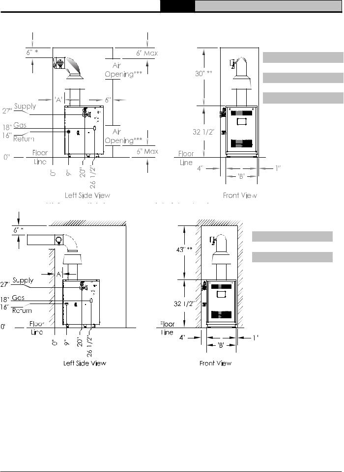
1.Minimum clearances to combustible materials are shown in Figure 4-1 and Figures 4-2.
Recommended for servicing: 24" minimum for left side front jacket panels..
2.Closet Installation -
Models 202E, 203E, 204E, 205E & 206E are listed for closet installation. See Figure 4-1.
3.Alcove installations (no front door) Models 207E, 208E & 209E are listed for Alcove installation. See Figure 4-2.
4.Hot water pipes: at least 1/2" from combustible material.
B.Provide Combustion and Ventilation Air in accordance with the section "Air for Combustion and Ventilation", of the National Fuel Gas Code, ANSI Z223.1/NFPA, or applicable provisions of local building codes.
109443-01 - 6/19 |
5 |
SERIES 2E Installation, Operating & Service Manual
4 Clearances (continued)
Model |
A |
B |
|
|
|
202E |
6" |
14" |
|
|
|
203E |
6" |
14" |
|
|
|
204E |
6" |
16" |
205E |
6" |
19" |
|
|
|
206E |
6" |
22" |
|
|
|
Figure 4-1: Minimum Closet Clearances
Model |
A |
B |
|
|
|
207E |
8" |
25" |
208E |
8" |
28" |
209E |
8" |
31" |
|
|
|
Figure 4-2: Minimum Alcove Clearances
*Minimum radial clearance around draft hood and vent connector.
**Additional height required to maintain 6" clearance from all vent connector components. Vent damper may be installed in vertical or horizontal section of vent connector within reach of vent damper harness.
***Area of each opening to be 1 sq. inch for each 1000 BTU/hr input - with minimum of 100 sq. inches. Height of opening should be half of width. 3" minimum dimension for air openings.
6 |
109443-01 - 6/19 |

SERIES 2E Installation, Operating & Service Manual
5 Venting
A.Inspect chimney and remove any obstructions or restrictions. Clean chimney if previously used for solid or liquid fuel-burning appliances or fireplaces.
B.Install vent system in accordance with "Venting of Appliances" of the National Fuel Gas Code,
ANSI Z223.1/NFPA 54, or applicable provisions of local building codes. The Series 2E boiler is a Category I, draft hood equipped appliance with vent damper.
1.Type B or Type L gas vent. Install in accordance with manufacturer's installation instructions.
2.Masonry or metal chimney. Build and install in accordance with local building codes; or local authority having jurisdiction; or Standard for Chimneys, Fireplaces, Vents, and Solid Fuel Burning Appliances, NFPA 211.
Masonry chimney must be lined with listed clay flue lining or listed chimney lining system.
3.Single wall metal vent. Allowed by ANSI Z223.1/NFPA 54 under very restrictive conditions.
4.Do not use CPVC, PVC, Polypropylene or any other non-metallic vent pipe. Do not use cellular core PVC (ASTM F891), cellular core CPVC, or Radel® (polyphenolsulfone).
5.Do not cover non-metallic vent pipe and fittings with thermal insulation.
C.Install Draft Hood without modification on outlet of flue collector. Secure with sheet metal screws.
! WARNING
Do not alter boiler draft hood or place any obstruction or non listed damper in breeching or vent system. Flue gas spillage and carbon monoxide production can occur.
D.Install Blocked Vent Switch
The blocked vent switch assembly shipped taped to the top of boiler includes a harness and a switch attached to a mounting bracket.
1.Position mounting bracket (with switch attached) onto lower edge of draft hood skirt by locating center tooth (with #10 sheet metal screw) on outside and other two teeth inside draft hood skirt. See Figure 5-1.
2.Slide mounting bracket up tight against lower edge of draft hood skirt, so that #10 sheet metal screw is above skirt's stiffening rib.
3.Be sure power cord, mounting bracket, and switch are secure and located as shown in Figure 5-1.
Figure 5-1 : Blocked Vent Switch
Installation Diagram
109443-01 - 6/19 |
7 |
SERIES 2E Installation, Operating & Service Manual
5 Venting (continued)
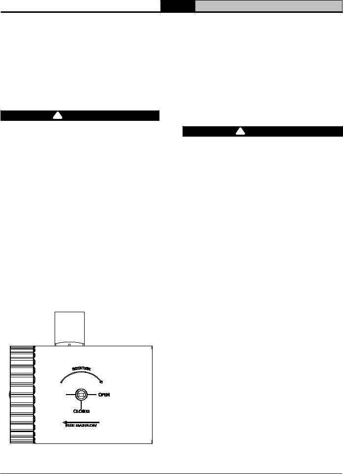
E.Install Vent Damper
OPEN THE VENT CAMPER CARTON and remove Installation Instructions. READ INSTALLATION INSTRUCTIONS THOROUGHLY before proceeding.
Automatic gas control valve supplied on each Series 2E boiler provides redundancy referenced in vent damper Installation Instructions.
! CAUTION
Do not use one vent damper to control more than one heating appliance.
1.Vent damper must be same size as outlet of vent supplied with boiler (see Table 1B).
Unpack damper carefully - DO NOT FORCE IT CLOSED! Forcing damper may damage motor and void warranty.
Insert pilot vent plug into gate and fold over tabs.
2.Mount the vent damper assembly onto draft hood. (Damper can be mounted vertically or horizontally). See damper manufacturer instructions for more information. Do not modify either draft hood or vent damper.
NOTICE: Provide adequate access for servicing.
3.Locate vent damper position indicator to be visible following installation.
4.Plug factory harness vent
damper connector into damper motor polarized receptacle.
Figure 5-2 : Vent Damper Position Indicator
5.For 2 section boiler only, install supplied vent reducer after damper. See Figure 5-1.
F.Install Vent Piping
1.Install vent piping from vent damper outlet to chimney.
2.Vent pipes serving appliances vented by natural draft shall not be connected into any portion of mechanical draft systems operating under positive pressure.
!DANGER
Inspect existing chimney before installing boiler. Look for corrosion holes. Failure to clean chimney or replace corroded pipe or tile lining will cause severe injury or death.
3.Do not connect into same flue of chimney serving an open fireplace.
4.Vent pipe to chimney must not be smaller than outlet on draft hood or vent damper. Arrange venting system so boiler is served by vent damper device.
Exception: National Fuel Gas Code, ANSI Z223.1/NFPA 54, and allow vent downsizing when vent size determined by their Vent Sizing Tables is smaller than draft hood outlet/vent damper. These codes require all of following:
a.Total vent height (H) is at least 10 ft;
b.Vent not reduced more than one table size;
and
c. Draft hood outlet/vent damper is greater than 4 in. in diameter.
5.Vent pipe should have greatest possible initial rise above draft hood consistent with head room available and required
clearance from adjacent combustible building structure. Vent pipe should be installed above bottom of chimney to prevent blockage.
6.Slope vent pipe upward from draft hood to vent terminal not less than 1/4" per foot.
7.Support horizontal portions of venting system to prevent sagging. Use pipe straps, brackets or hangers spaced 4 ft. or less.
8.Vent pipe must be inserted into but not beyond inside wall of chimney liner. Seal tight between vent pipe and chimney.
8 |
109443-01 - 6/19 |

SERIES 2E Installation, Operating & Service Manual
5 Venting (continued)
G.Install vent termination (Masonry chimney and single wall metal pipe)
1.Termination shall extend at least 5 ft.
in vertical height above highest connected appliance vent outlet.
2.Termination shall extend at least 3 ft. (2 ft. for single wall metal pipe) above roof penetration and at least 2 ft. above any portion of building within horizontal distance of 10 ft.
H.Install vent termination: (Gas Vent)
1.Termination shall extend at least 5 ft.
in vertical height above highest connected appliance vent outlet.
Figure 5-3 : Termination Location for Gas Vent
2.For terminations located at least 8 ft. from vertical wall or similar obstruction, termination shall extend above roof in accordance with Figure 5-3.
3.For terminations located less than 8 ft. from vertical wall or similar obstruction, termination shall extend at least 2 ft. above roof penetration and at least 2 ft. above any portion of building within horizontal distance of 10 ft.
4.Termination shall be at least 3 ft. above forced air inlet located within 10 ft.
Roof Slope Heights
Roof Slope |
ft. |
|
|
Flat to 6/12 |
1.0 |
Over 6/12 to 7/12 |
1.25 |
Over 7/12 to 8/12 |
1.5 |
Over 8/12 to 9/12 |
2.0 |
Over 9/12 to 10/12 |
2.5 |
Over 10/12 to 11/12 |
3.25 |
Over 11/12 to 12/12 |
4.0 |
Over 12/12 to 14/12 |
5.0 |
Over 14/12 to 16/12 |
6.0 |
Over 16/12 to 18/12 |
7.0 |
Over 18/12 t 20/12 |
7.5 |
Over 20/12 to 21/12 |
8.0 |
109443-01 - 6/19 |
9 |

SERIES 2E Installation, Operating & Service Manual
6 Water Piping
! WARNING
Failure to properly pipe boiler may result in improper operation and damage to boiler or building.
A.Design and install boiler and system piping to prevent oxygen contamination of boiler water.
Oxygen contamination sources are system leaks requiring addition of makeup water, fittings,
and oxygen permeable materials in distribution system. Eliminate oxygen contamination by repairing system leaks, repairing fittings, and using non-permeable materials in distribution system.
B.Install circulator with flanges, gaskets and bolts provided.
!WARNING
Safety relief valve discharge piping must be piped near floor to eliminate potential of severe burns. Do not pipe in any shut-off valves between:
1.Safety relief valve and boiler
2.Safety relief valve and discharge
Union may be installed in safety relief valve piping.
C.Install safety relief valve. See Figure 6-1. Safety relief valve must be installed with spindle in vertical position.
D.Connect system supply and return piping to boiler. Refer to Figures 6-2 and 6-3. Also consult Residential Hydronic Heating Installation and Design I=B=R Guide. Maintain minimum ½ inch clearance from hot water piping to combustible materials.
E.If boiler is used in connection with refrigeration system, See Appendix: "Combination Refrigeration/Heating System".
F.Use a system bypass if boiler is to be operated in a system which has a large volume or excessive radiation where low boiler water temperatures may be encountered (i.e. converted gravity circulation system, etc.). (See Appendix "Low Return Water Temperatures").
G.Perform a long term pressure test of hydronic system, isolate boiler to avoid a pressure loss due to escape of air trapped in boiler.
To perform a long term pressure test including the boiler, ALL trapped air must first be removed from the boiler.
A loss of pressure during such a test, with no visible water leakage, is an indication that the boiler contained trapped air.
Figure 6-1: Near Boiler Piping
10 |
109443-01 - 6/19 |
6/19 - 01-109443
|
Full Port |
To |
Isolation |
Valves |
|
System |
|
Flow Check
Zone Circulators
Optional Circulator Zone
Controlled System
To
System
System
Zone
Valves
System
Circulator
Optional Zone Valve
Controlled System
11
At least 18" of straight pipe for conventional air separator
Air Separator
& Air Vent
|
IWH |
|
|
Supply |
|
Full Port |
Expansion |
|
Tank |
||
Isolation |
||
|
Valve
Flow Check
IWH Circulator
Unions
From System
Fill
Valve
Full Port
Isolation
Cold Valves
Water
Return
Backflow
Preventer
Full Port
Isolation
Valve
Unions
IWH
Return
Indirect Water Heater (IWH)
Figure 6-2: Recommended Water Piping Direct Connection System
|
6 |
Full Port |
Water |
Isolation |
|
Valves |
|
|
Piping |
Drain Valve |
(continued) |
Pipe within 6" |
|
of floor or drain |
|
Safety Relief Valve
Drain Valve
Manual Service & Operating Installation, 2E SERIES
12
6/19 - 01-109443
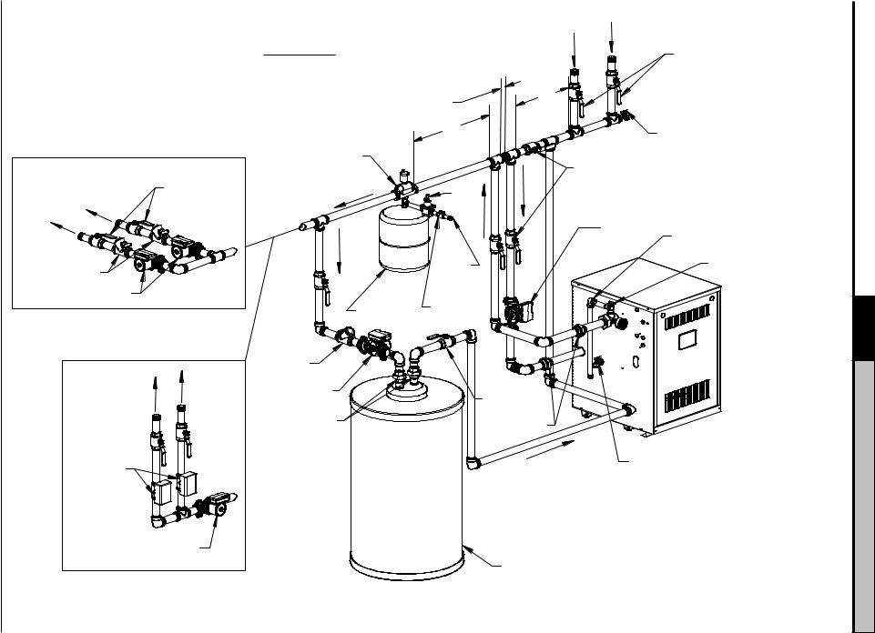
A.At least eight pipe diameters upstream of boiler return tee.
B.No further apart than 12" (~30cm) or four pipe diameters, whichever is smaller.
C.At least 18" (~46cm) of straight pipe for Conventional Air Scoop.
|
|
'B' |
|
|
'C' |
|
|
Air Separator |
|
Full Port |
& Air Vent |
|
Fill |
|
To |
Isolation |
|
Valves |
Valve |
|
System |
|
|
From System
Full Port
Isolation
Valves
'A'
Drain Valve
Full Port
Isolation
Valves
Flow Check
Zone Circulators
Optional Circulator Zone
Controlled System
To
System
System
Zone
Valves
System
Circulator
Optional Zone Valve
Controlled System
|
IWH |
|
|
Supply |
|
Full Port |
Expansion |
|
Tank |
||
Isolation |
||
|
Valve
Flow Check
IWH Circulator
Unions
Cold
Water
Return
Backflow
Preventer
Circulator |
Pipe within 6" |
|
of floor or drain |
|
Safety Relief Valve |
Full Port
Isolation
Valve
Unions
IWH |
Drain Valve |
|
Return |
||
|
Indirect Water Heater (IWH)
Figure 6-3: Recommended Piping for Primary Secondary System
(continued) Piping Water 6
Manual Service & Operating Installation, 2E SERIES

SERIES 2E Installation, Operating & Service Manual
7 Gas Piping
A. Size gas piping. Design system to provide adequate gas supply to boiler. Consider these factors:
1. Allowable pressure drop from point of delivery to boiler. Maximum allowable system pressure is ½ psig. Minimum gas valve inlet pressure is listed on rating label. See Table 7-1.
Table 7-1: Gas Pressure
|
Natural |
Inlet Min |
Inlet Max |
Manifold |
|
Gas |
(in. wc.) |
(in. wc.) |
(in. wc.) |
|
All Sizes |
4.5 |
14.0 |
3.5 |
|
|
|
|
|
|
LP |
Inlet Min |
Inlet Max |
Manifold |
|
(in. wc.) |
(in. wc.) |
(in. wc.) |
|
|
|
|||
|
All Sizes |
11.0 |
14.0 |
10.0 |
Figure 7-2: Gas Piping
2.Maximum gas demand. Consider existing and expected future gas utilization equipment (i.e.
water heater, cooking equipment). B. Connect boiler to gas supply system.
1. Use methods and materials in accordance with local plumbing codes and requirements of gas
supplier. In absence of such requirements, follow National Fuel Gas Code, ANSI Z223.1/ NFPA 54.
2. Use thread compounds (pipe dope) resistant to action of liquefied petroleum gas.
3. Install sediment trap, ground-joint union and manual shut-off valve upstream of boiler gas control valve. See Figure 7-2 (within 6 ft. of boiler).
4. All above ground gas piping upstream from manual shut-off valve must be electrically
continuous and bonded to a grounding electrode. Do not use gas piping as grounding electrode. Refer to National Electrical Code,
ANSI/NFPA 70.
C. Pressure test. Boiler and its gas connection must be leak tested before placing boiler in operation.
See Startup and Checkout Section E and H " Gas
Leak Test" for guidance.
Figure 7-3: Gas Manifold and Control Assembly
109443-01 - 6/19 |
13 |

SERIES 2E Installation, Operating & Service Manual
8 Electrical
! WARNING
Electrical Shock Hazard. Wiring errors can cause improper or dangerous operation. Verify proper operation after installation.
A.Install wiring so boiler is electrically bonded to ground in accordance with requirements of
authority having jurisdiction, or in absence of such requirements, with the National Electrical Code,
ANSI/NFPA 70.
B.Install thermostat. Locate on inside wall approximately 4 feet above floor. Do not install on outside wall, near fireplace, or where influenced by drafts or restricted air flow, hot or cold water pipes, lighting fixtures, television, or sunlight. Allow free air movement by avoiding placement of furniture near thermostat.
C.Wire boiler. Boiler is rated for 120 VAC, 60 HZ, less than 12 A. A separate electrical circuit must be run from the main electrical service with an over-current device/disconnect in the circuit. A service switch is recommended and may be required by some local jurisdictions. Connect to black and white wires and green ground screw. See Figures 8-1 and 8-2.
D.For installations using zone valves provide separate transformer for zone valve wiring. Consult zone valve manufacturer for assistance. See Appendix: "Wiring Schematics".
! CAUTION
This boiler contains controls which may cause the boiler to shut down and not restart without service. If damage due to frozen pipes is a possibility, the heating system should not be left unattended in cold weather; or appropriate safeguards and alarms should be installed on the heating system to prevent damage if the boiler is inoperative.
14 |
109443-01 - 6/19 |

SERIES 2E Installation, Operating & Service Manual
8 Electrical (continued)
|
Figure 8-1: Wiring Connection Diagram |
109443-01 - 6/19 |
15 |

SERIES 2E Installation, Operating & Service Manual
8 Electrical (continued)
Figure 8-2: Schematic Ladder Diagram
16 |
109443-01 - 6/19 |
 Loading...