

Page 1

Network Fixed Dome Cameras
Quick Guide
Manual Version: V1.01
Page 2

Thank you for purchasing our product. If there are any questions,
or requests, please do not hesitate to contact the dealer.
Copyright
Copyright 2015 Zhejiang Uniview Technologies Co., Ltd. All rights
reserved. No part of this manual may be copied, reproduced,
translated, or distributed in any form or by any means without
prior consent in writing from our company.
Trademark Acknowledgement
and other Uniview’s trademarks and logos are the
property of Zhejiang Uniview Technologies Co., Ltd. Other
trademarks, company names and product names contained in this
manual are the property of their respective owners.
Page 3
Disclaimer
The default password is used for your first login. To ensure
account security, please change the password after your first
login. You are recommended to set a strong password (no
less than eight characters).
To the maximum extent permitted by applicable law, the
product described, with its hardware, software, firmware
and documents, is provided on an "as is" basis.
Best effort has been made to verify the integrity and
correctness of the contents in this manual, but no statement,
information, or recommendation in this manual shall
constitute formal guarantee of any kind, expressed or
implied. We shall not be held responsible for any technical or
typographical errors in this manual. The contents of this
manual are subject to change without prior notice. Update
will be added to the new version of this manual.
Use of this manual and product and the subsequent result
shall be entirely on your own responsibility. In no event shall
we be reliable to you for any special, consequential,
incidental, or indirect damages, including, among others,
damages for loss of business profits, business interruption,
or loss of data or documentation, or product malfunction or
Page 4

information leakage caused by cyber attack, hacking or virus
in connection with the use of this product.
Video and audio surveillance can be regulated by laws that
vary from country to country. Check the law in your local
region before using this product for surveillance purposes.
We shall not be held responsible for any consequences
resulting from illegal operations of the device.
The illustrations in this manual are for reference only and
may vary depending on the version or model. As a result,
some of the examples and functions featured may differ
from those displayed on your monitor.
This manual is a guide for multiple product models and so it
is not intended for any specific product.
Due to uncertainties such as physical environment,
discrepancy may exist between the actual values and
reference values provided in this manual. The ultimate right
to interpretation resides in our company.
Environmental Protection
This product has been designed to comply with the requirements
on environmental protection. For the proper storage, use and
disposal of this product, national laws and regulations must be
observed.
Page 5
Safety and Compliance Information
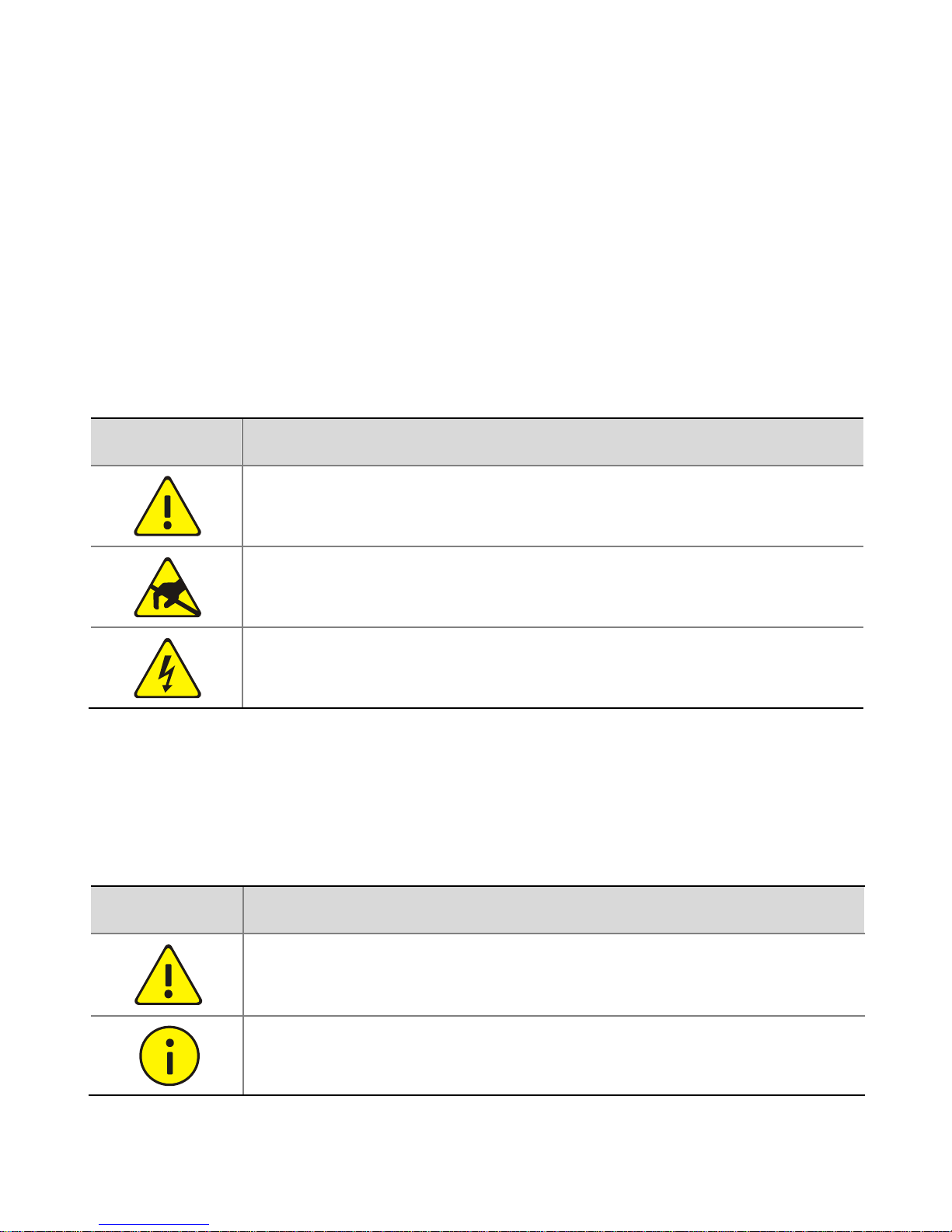
Safety Symbols
The symbols in the following table may be found on
installation-related equipment. Be aware of the situations
indicated and take necessary safety precautions during
equipment installation and maintenance.
Symbol
Description
Generic alarm symbol: To suggest a general safety
concern.
ESD protection symbol: To suggest
electrostatic-sensitive equipment.
Electric shock symbol: To suggest a danger of high
voltage.
The symbols in the following table may be found in this manual.
Carefully follow the instructions indicated by the symbols to avoid
hazardous situations and use the product properly.
Symbol
Description
WARNING! Indicates a hazardous situation which, if
not avoided, could result in bodily injury or death.
CAUTION! Indicates a situation which, if not
avoided, could result in damage, data loss or
Page 6
Symbol
Description
malfunction to product.
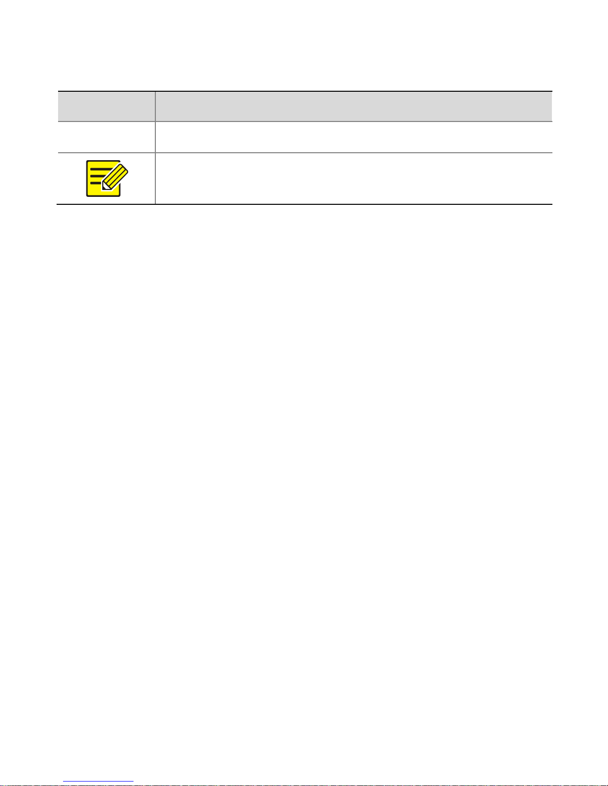
NOTE! Indicates useful or supplemental information
about the use of product.
Safety Information
Installation and removal of the unit and its accessories must be
carried out by qualified personnel. Please read all of the safety
instructions below before installation and operation.
Installation
This device is a class A product and may cause radio
interference. Take measures if necessary.
If the product does not work properly, please contact your
dealer. Never attempt to disassemble the camera yourself.
(We shall not assume any responsibility for problems caused
by unauthorized repair or maintenance).
Avoid squashing, shaking, or damping the camera during
transport, storage, and mounting. Keep the camera from
vibration sources during mounting.
Please make sure that the ceiling can support more than
50(N) Newton gravities if the camera is fixed to the ceiling.
Page 7

Make sure the power supply voltage is correct before using
the camera. Use a proper power adapter or a PoE power
supply device. An improper power adapter may damage your
camera.
Disconnect the power before moving the camera, and take
cautions to avoid electric shock when moving it. Once the
cable is connected to the mains, the camera will be
powered.
During mounting, do not remove the protective film in the
outer layer of housing to keep it clean. After finishing the
mounting, remove the film when camera is powered off.
Verify that the length of the power cable between the power
adapter and the camera does not exceed 1.5 m. If the power
cable is longer than 1.5 m, the voltage of the camera is
lowered, causing the camera to work improperly. If it is
required to lengthen the power cable, lengthen the cable
between the power adapter and the mains.
Do not hold the tail cable by hand for weight bearing.
Otherwise, the cable connector of the camera could be
loosened.
Do not cut off the tail cable for connection purposes. A bare
tail cable may easily cause a short circuit, resulting in
abnormality of or damage to the camera.
Page 8

Use the waterproof tapes to protect the end of tail cable,
and keep the tail cable from water.
When connecting to an external interface, use an existing
connection terminal, and ensure that the cable terminal
(latch or buckle) is in good condition and properly fastened.
Ensure that the cable is not tense during mounting, with a
proper margin reserved to avoid poor port contact or
loosening caused by shock or shake.
Ensure that the high-level signal of the alarm input is not
higher than 5 VDC when the alarm input interface is
connected.
As is often the case in the industry, dome housings tend to
have static electricity. To prevent dust absorption by the
static electricity, it is recommended to clean the dome
housing surface with antistatic gloves after removing the
protective film.
Do not touch sensor modules with fingers. If cleaning is
necessary, use a clean cloth with a bit of ethanol and wipe it
gently. If the camera will not be used for an extended period
of time, put on the lens cap to protect the sensor from dirt.
Do not aim the camera lens at the strong light such as sun or
incandescent lamp. The strong light can cause fatal damage
to the camera.
Page 9

The sensor may be burned out by a laser beam, so when any
laser equipment is being used, make sure that the surface of
the sensor not be exposed to the laser beam.
Maintenance
If there is dust on the lens or the transparent dome cover,
remove the dust gently using an oil-free brush or a rubber
dust blowing ball.
If there is grease on the lens, remove the grease using an
oil-free cloth gently and then clean the lens in a circular
spiral from the center outward using an oil-free cloth or a
lens cleaning paper dipped with small amount of cleaning
solution. If the grease still cannot be removed, change
another oil-free cloth or lens cleaning paper and clean the
lens gently until it is removed.
If there is grease or a dust stain on the transparent dome
cover, clean the cover gently from the center outward using
anti-static gloves or an oil-free cloth. If the grease or the
stain still cannot be removed, use anti-static gloves or an
oil-free cloth dipped with detergent and clean the dome
cover gently until it is removed.
Do not use organic solvents, such as benzene or ethanol
when cleaning the transparent dome cover.
Page 10
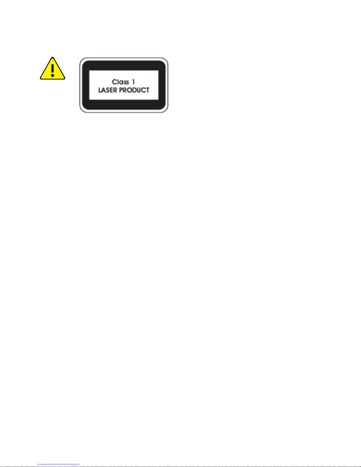
Never look at the transmit laser while the power is on.
Never look directly at the fiber ports and the fiber
cable ends when they are powered on.
Use of controls or adjustments to the performance or
procedures other than those specified herein may
result in hazardous laser emissions.
Regulatory Compliance
FCC Part 15
This equipment has been tested and found to comply with the
limits for digital device, pursuant to part 15 of the FCC Rules.
These limits are designed to provide reasonable protection
against harmful interference when the equipment is operated in a
commercial environment. This equipment generates, uses, and
can radiate radio frequency energy and, if not installed and used
in accordance with the instruction manual, may cause harmful
interference to radio communications. Operation of this
equipment in a residential area is likely to cause harmful
Page 11
interference in which case the user will be required to correct the
interference at his own expense.
This product complies with Part 15 of the FCC Rules. Operation is
subject to the following two conditions:
1. This device may not cause harmful interference.
2. This device must accept any interference received, including
interference that may cause undesired operation.
LVD/EMC Directive
This product complies with the European Low Voltage Directive
2006/95/EC and EMC Directive 2004/108/EC.
Page 12
WEEE Directive–2002/96/EC
The product this manual refers to is covered by the Waste
Electrical & Electronic Equipment (WEEE) Directive and must be
disposed of in a responsible manner.
Page 13

i
Contents
1 Appearance ........................................................................... 1
Dimensions and Appearance ................................................... 1
Cable Connection ..................................................................... 2
Camera Structure ..................................................................... 4
2 Installation ............................................................................ 5
Hardware Installation .............................................................. 6
Insert the Micro SD Card (Optional) .................................... 6
Mount your Camera ............................................................ 9
Start the Camera ............................................................... 37
Reset the Camera to Default Settings ............................... 37
Waterproof Measures ............................................................ 38
Waterproof Components for an RJ45 Plug ....................... 38
Waterproof Tail Cable ....................................................... 41
Page 14

ii
3 Set Your Camera over the LAN .............................................. 43
4 Access Your Camera .............................................................. 45
System Requirements for Your PC ......................................... 45
Access Your Camera ............................................................... 46
Install the ActiveX .................................................................. 47
Adjust the Display .................................................................. 48
Page 15
1
1 Appearance
Dimensions and Appearance
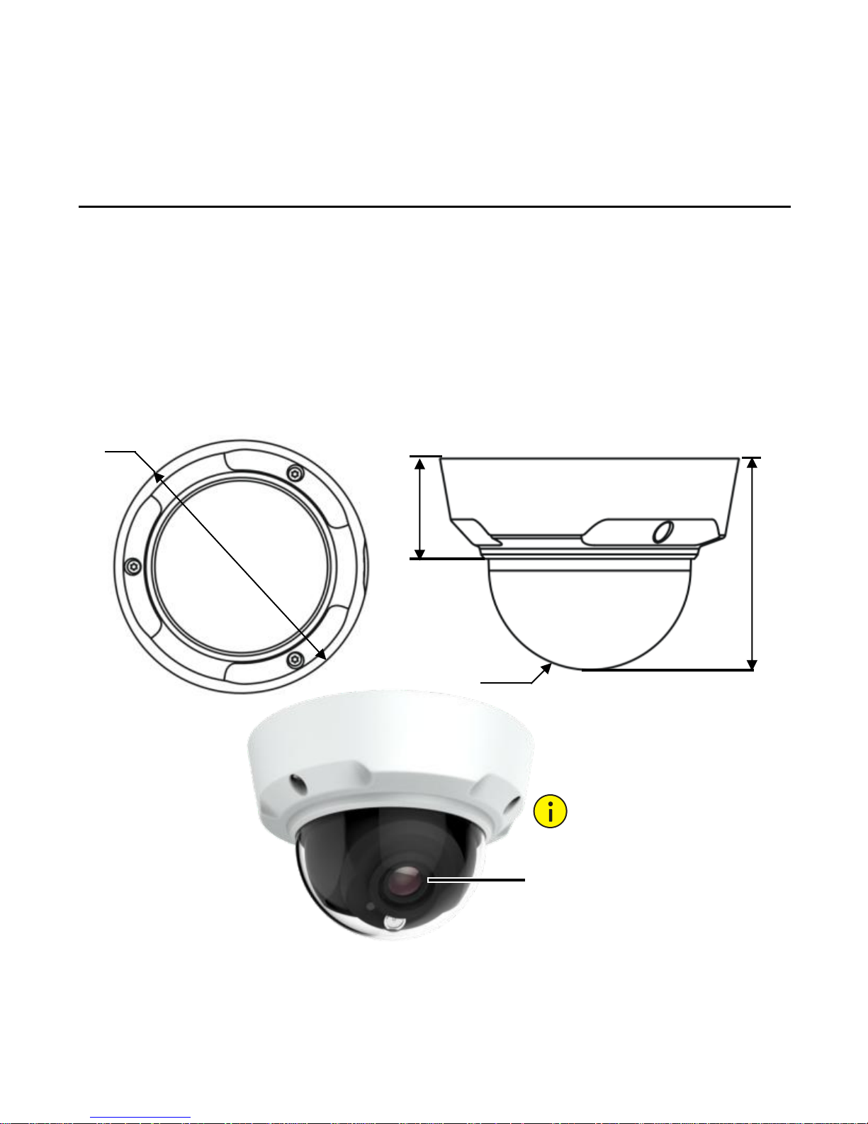
The following takes the infrared camera as an example. The actual
appearance may vary with the product. For the detailed
information about the product, please refer to the datasheet.
50 mm
105 mm
R 50 mm
Φ149 mm
(5.9”)
(4.1”)
(2.0”)
(2.0”)
Do not remove this shield ring
as the ring is used to reduce
the interference caused by
infrared entering the lens.
Page 16
2
Cable Connection
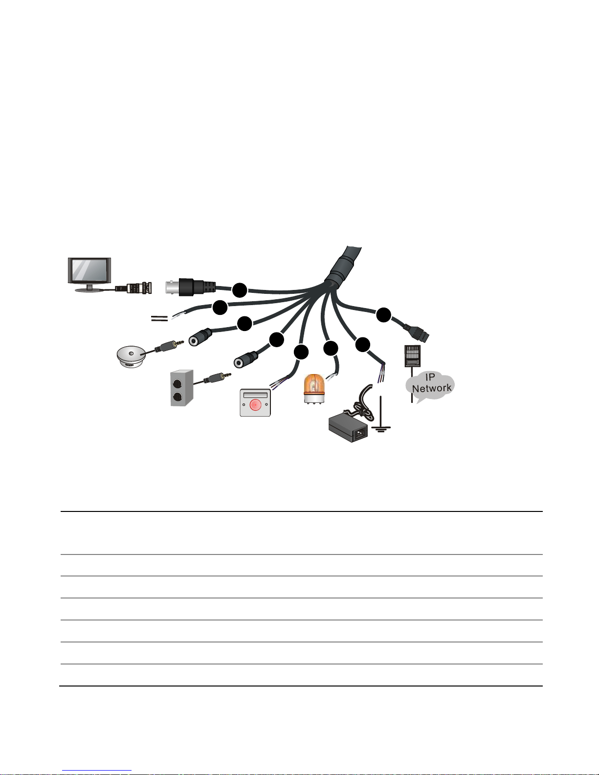
All the cables are tagged to indicate their functions. This section
takes full cable as an example. You can connect cables by referring
to the following figure.
1: Local video output interface (outputting composite video
signals), BNC connector
2: RS485 serial port
3: Audio input
4: Audio output
5: Alarm input
6: Alarm output
7: Power interface. The white cable is used to ground the camera.
Display
device
Third-party
device connected
through RS485
interface
Audio input
(Sound pickup)
Audio output
(Outdoor sound
box)
Alarm input
(Voice
activated
switch)
Alarm
output
(Alarm
indicator)
Power
adapter
1
2
3
4
5
6
7
8
Network
access device
connected
through
copper
interface
Page 17
3
Note:
The power interface can serve as a 12 VDC power input interface,
or serve as a power output interface to support the charging
function (see datasheet).
8: 10M/100M Base-TX adaptive Ethernet interface, RJ45
For the latest specifications, see the product datasheets.
Page 18
4
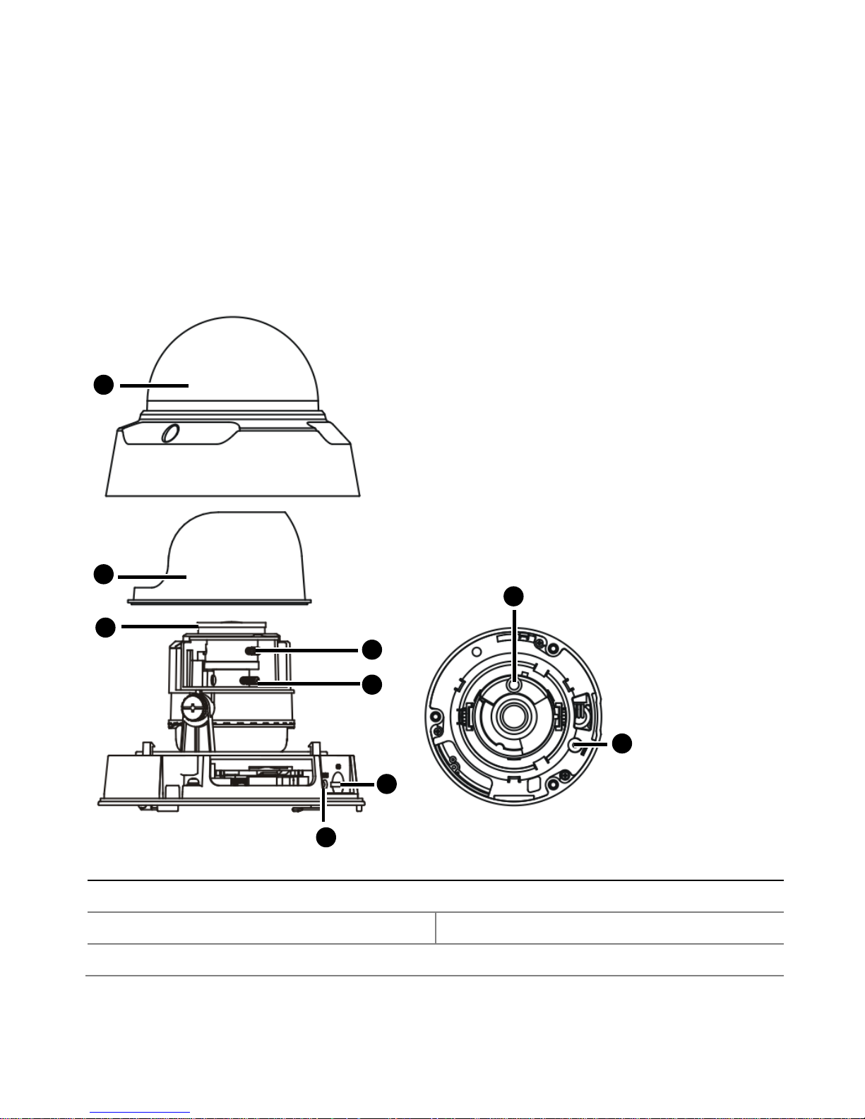
Camera Structure
The camera structure may vary with your product.
Figure 1 Camera Structure
1: Front cover (containing a transparent dome bubble)
2: Lining
3: Darkening ring
4: Focusing knob (supported by manual-focusing cameras)
12345
678
9
Page 19
5
5: Zooming knob (supported by manual-focusing cameras)
6: Micro SD card slot
7: System status indicator
Note:
The indicator has the following states: If the indicator is yellow,
the system is being started; if green, the system has been started;
if red, a device alarm is generated.
8: Infrared lamp (supported only by infrared cameras)
9: Reset button
Note:
Press and hold the Reset button for about 15 seconds to restore
factory default settings. The reset button only works within ten
minutes after the device is powered on. Some model may not
support this function, please refer to the actual internal structure.
2 Installation
There are two types of cameras (metal type and plastic
type). The following mounting steps are for your reference
only. Please install your camera according to the actual
product and field conditions.
Page 20
6
Hardware Installation
Insert the Micro SD Card (Optional)
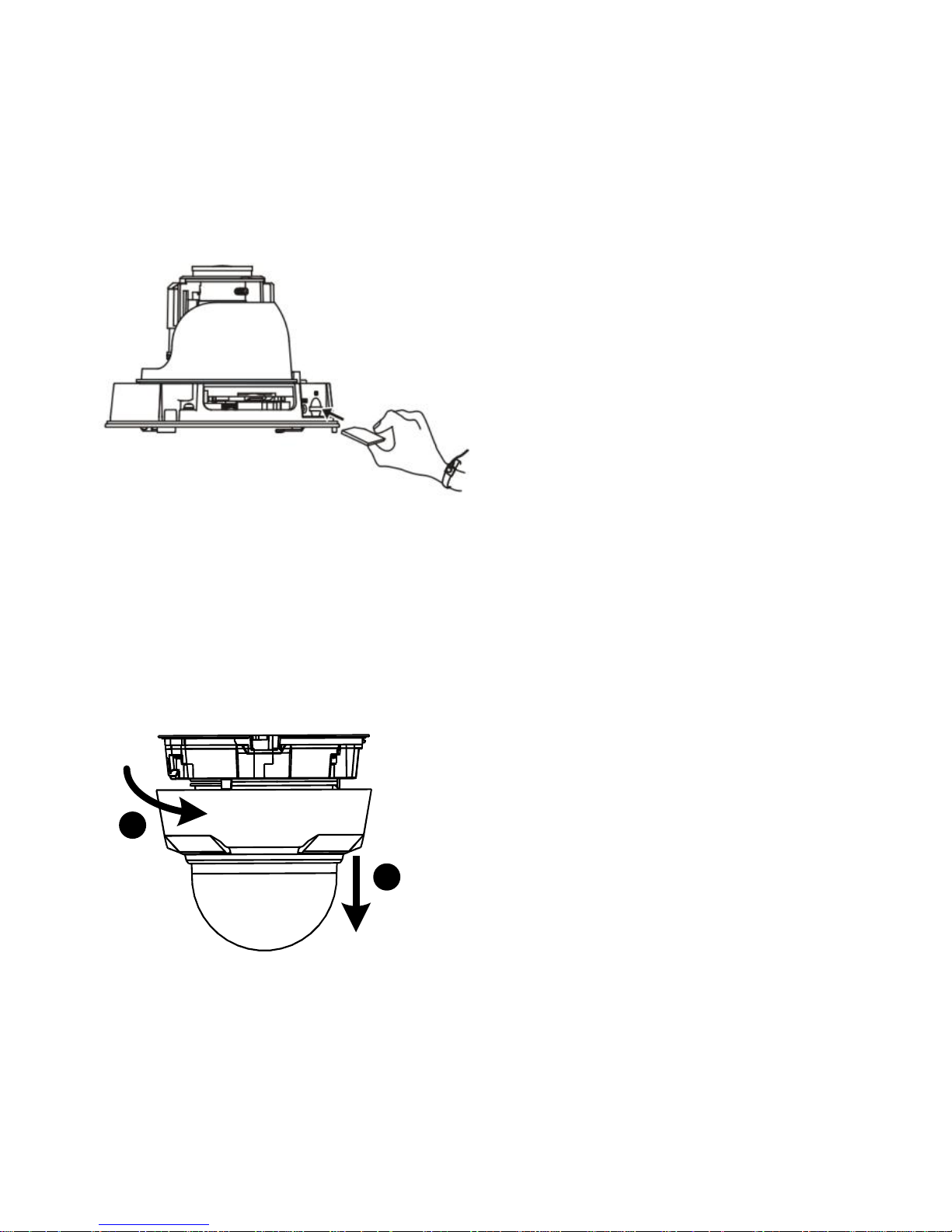
The Micro SD card slot is inside the camera. Therefore, you need
to open the bottom cover of the camera. Do not hot plug the
Micro SD card after it is inserted. Otherwise the camera or the SD
card might be damaged.
For details about recommended SD card specifications,
contact your dealer.
Metal Camera
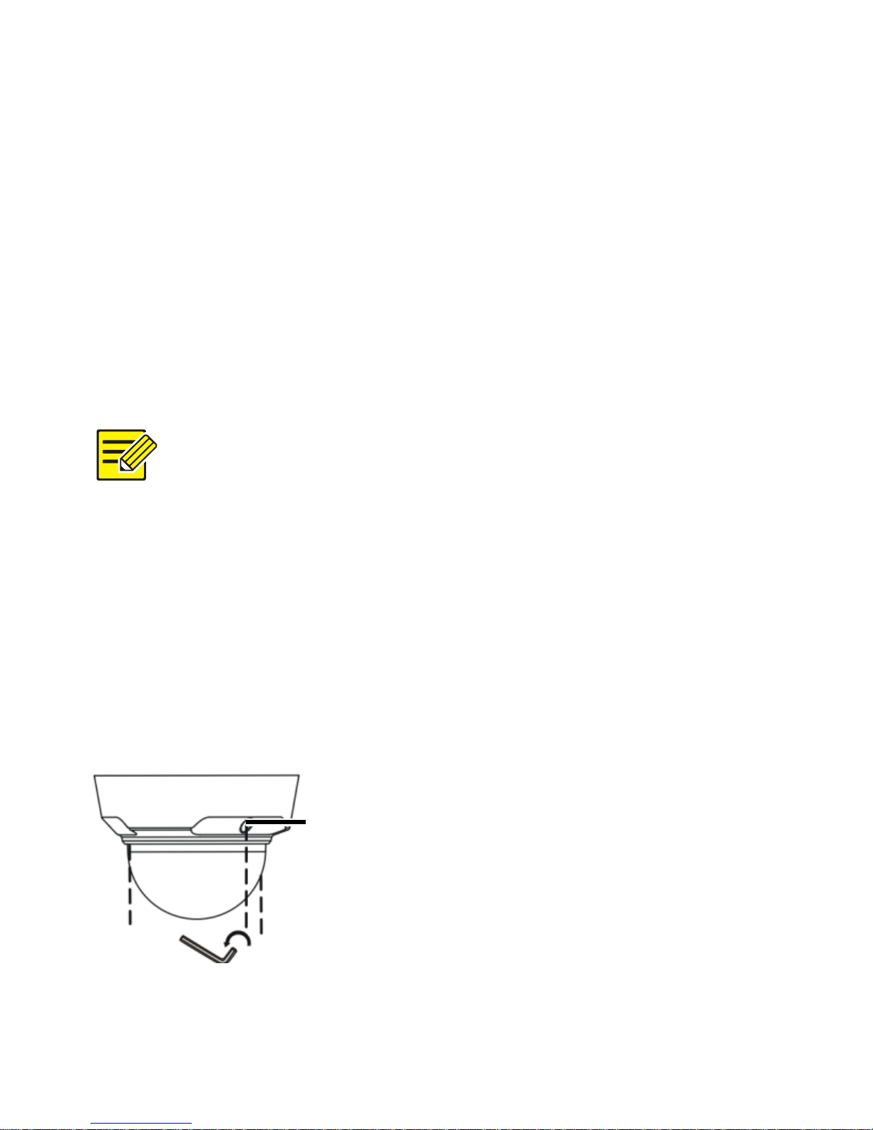
1. Remove the dome bubble
Remove the three socket fillister-head screws along the edge
of the transparent dome bubble.
Socket
fillister-head
screw
Page 21
7
2. Insert the Micro SD card into the slot.
Insert the Micro SD card and mount the dome bubble.
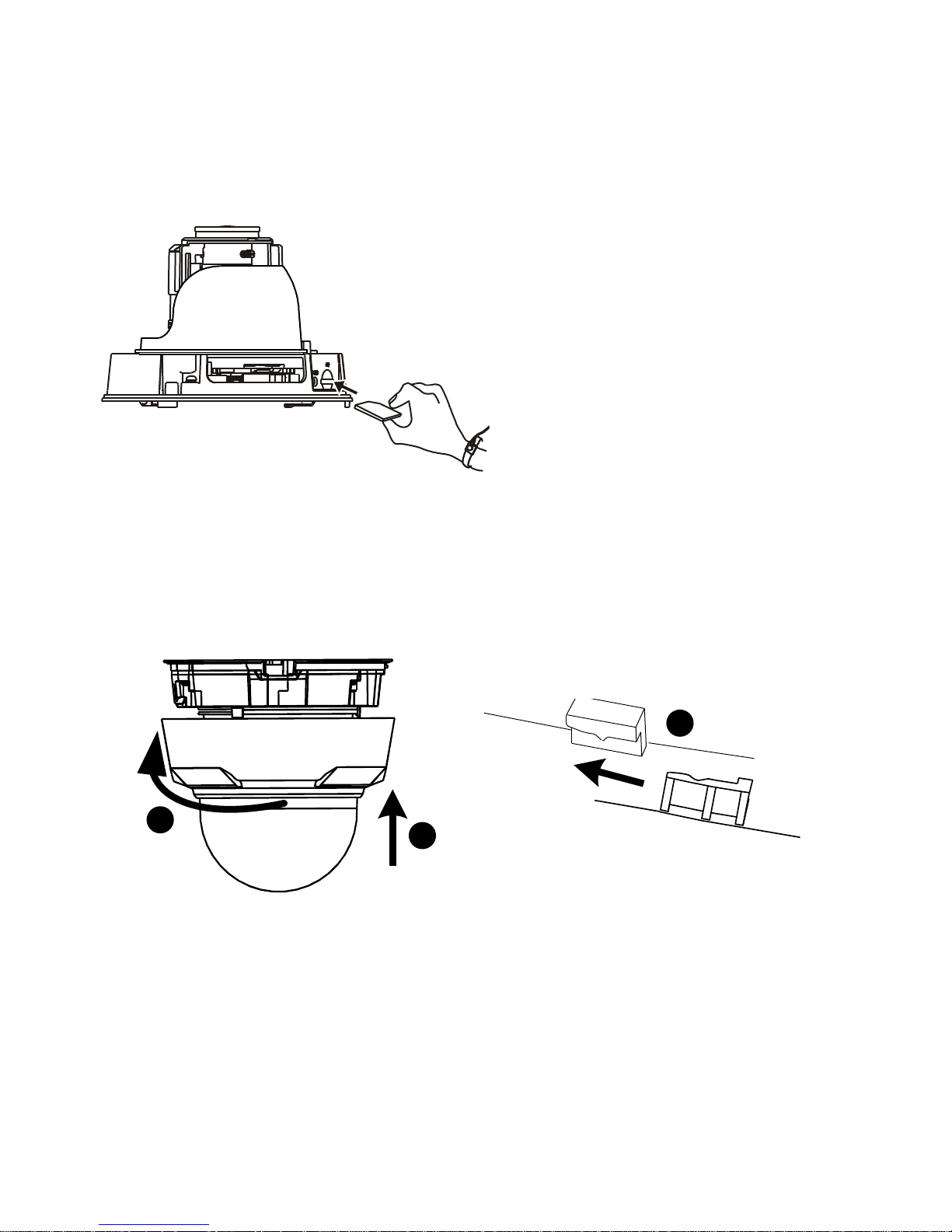
Plastic Camera
1. Remove the dome bubble.
1
2
Loosen dome bubble in
“open” direction.
Page 22
8
2. Insert the SD card.
3. Replace the dome bubble.
Rotate dome bubble (opposite to “open"
direction) till it clicks into position.
1
3
2
Page 23
9
Mount your Camera
Metal Camera
Ceiling Mount
When mounting the camera on the wall or ceiling, ensure that
the wall or ceiling can hold self-tapping screws and bear the
weight of the camera. The ceiling bracket is delivered with the
camera.
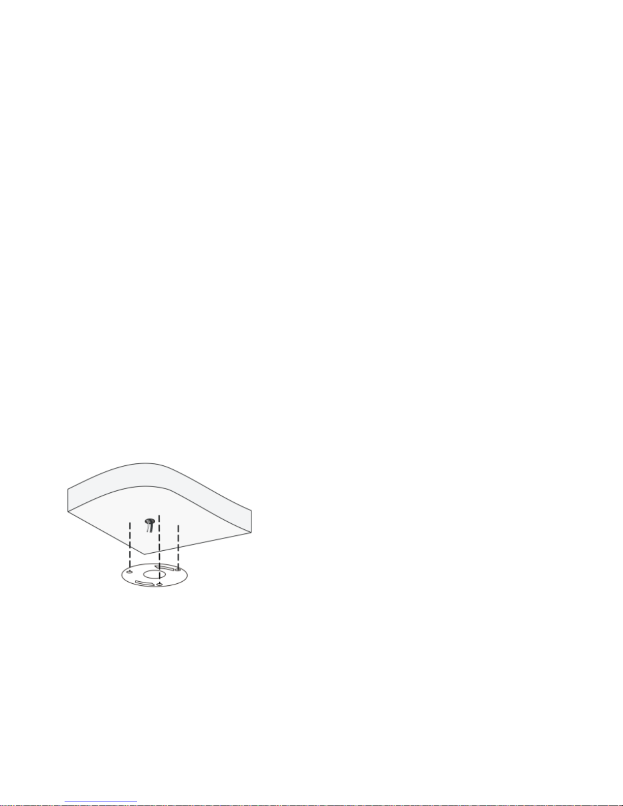
1. Locate the positions of the holes.
Paste installation positioning stickers on the ceiling. Lead the
cables across the hole on the wall.
Page 24
10
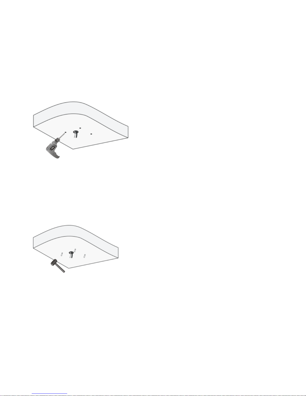
2. Drill holes on the wall.
Use a Ø 6-6.5mm drill bit to drill 30 mm-depth guide holes
according to the positions marked by stickers.
3. Mount the plastic rivets of self-tapping screws.
Knock the plastic rivets into the guide holes and ensure that
they are tightened up.
Page 25
11
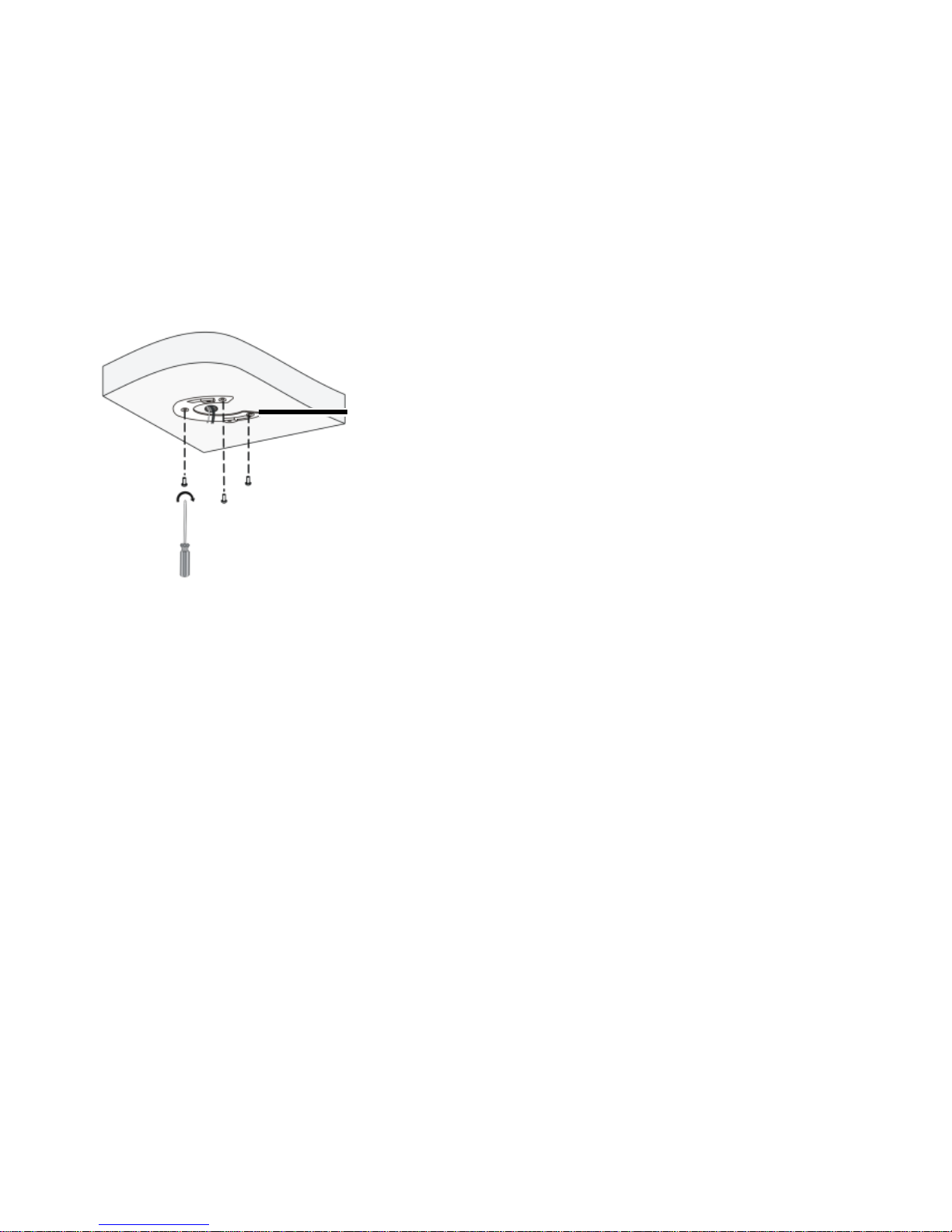
4. Mount the ceiling bracket.
Lead self-tapping screws through the guide holes in the base
and fix them on the ceiling by using a screwdriver.
5. Connect all cables.
Ceiling
bracket
Page 26
12
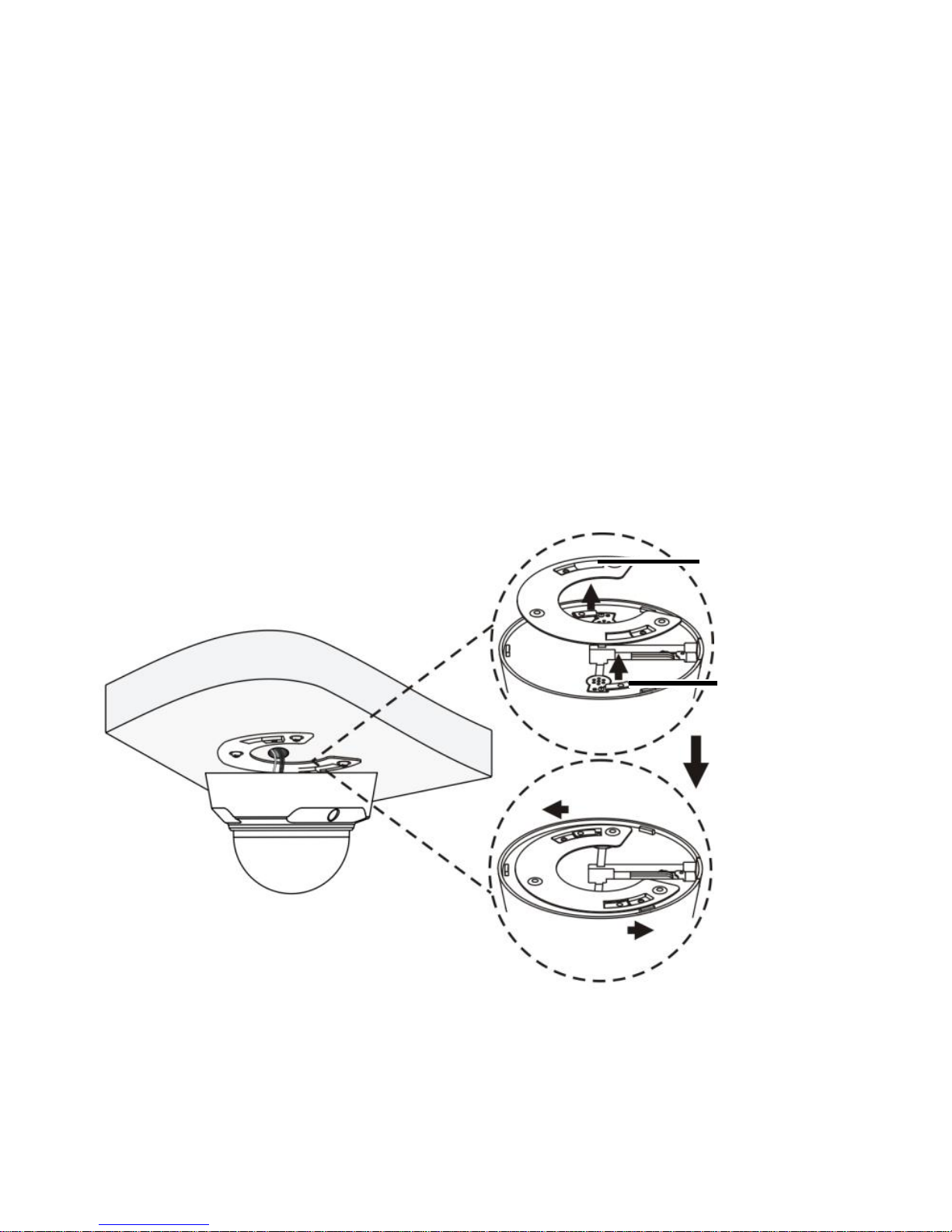
6. Fix the camera and ceiling bracket.
a. Align the two buckles at the top of the camera to the
opening holes of the ceiling bracket and push the camera
upward.
b. Rotate the camera in the direction shown in the following
figure and ensure that the camera is clamped by the
ceiling bracket.
Buckle
Hole
Page 27
13
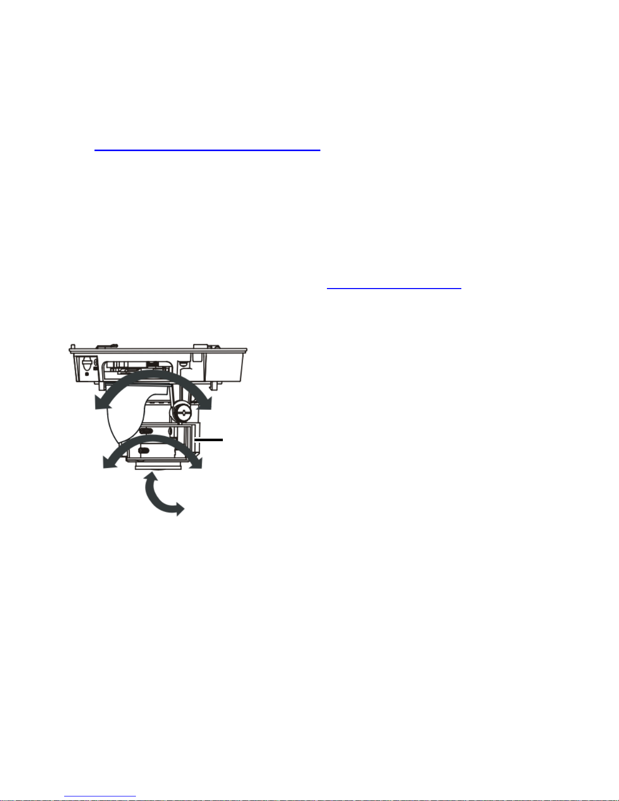
7. Remove the transparent dome bubble by referring to
Remove the dome bubble and adjust the monitoring
direction of the lens.
The lens can be rotated horizontally and vertically.
When you adjust infrared camera lens, put the infrared
indicator below the lens (see Camera Structure). Otherwise,
light supplementation could be abnormal.
Dome
Page 28
14
8. When you adjust the camera vertically, loosen the fixing
screws on both sides lightly, rotate the camera to the
desired monitoring direction and then fasten the screws.
Please stop rotating the camera when the spacing point is
blocked, otherwise the camera lens might be damaged.
Spacing Point
Screw
Page 29
15
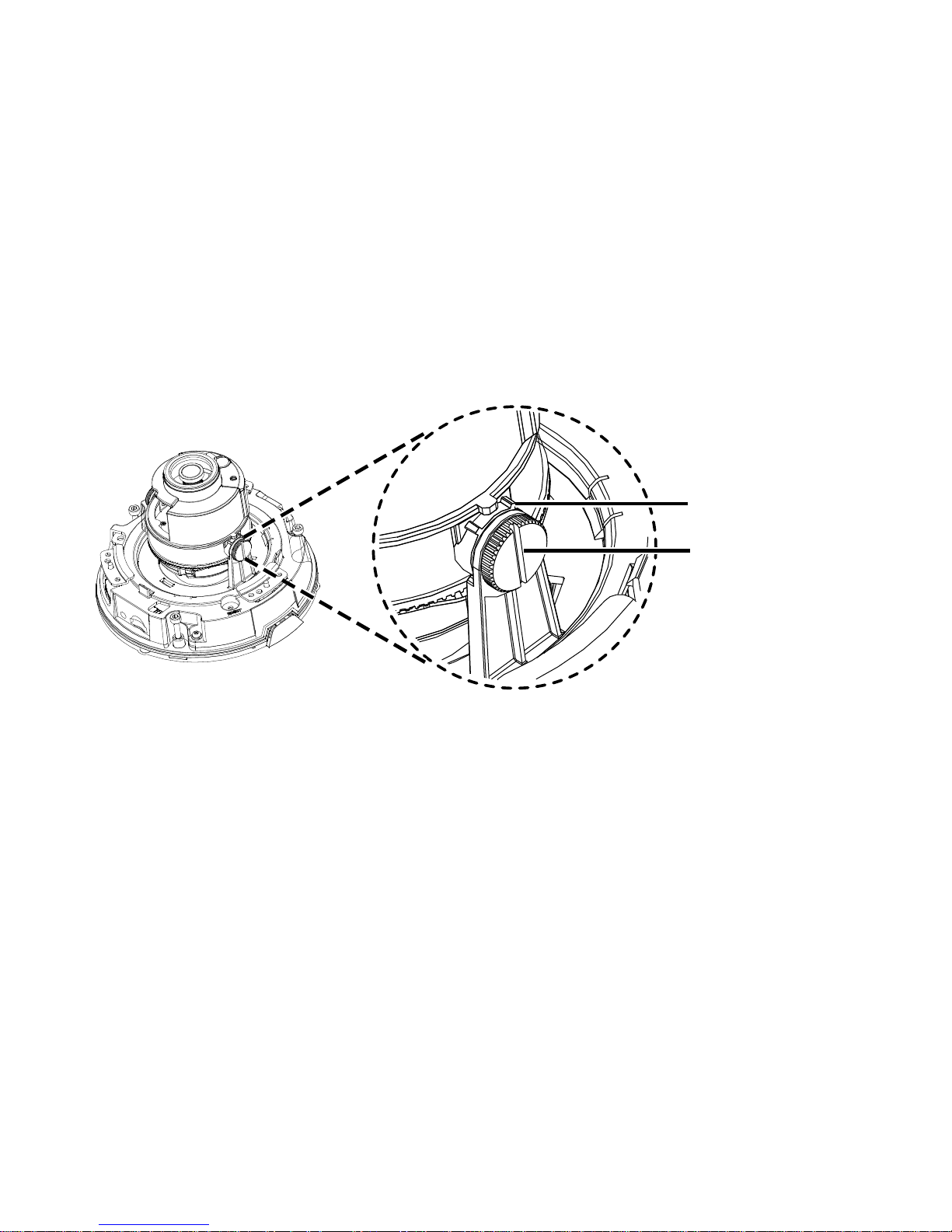
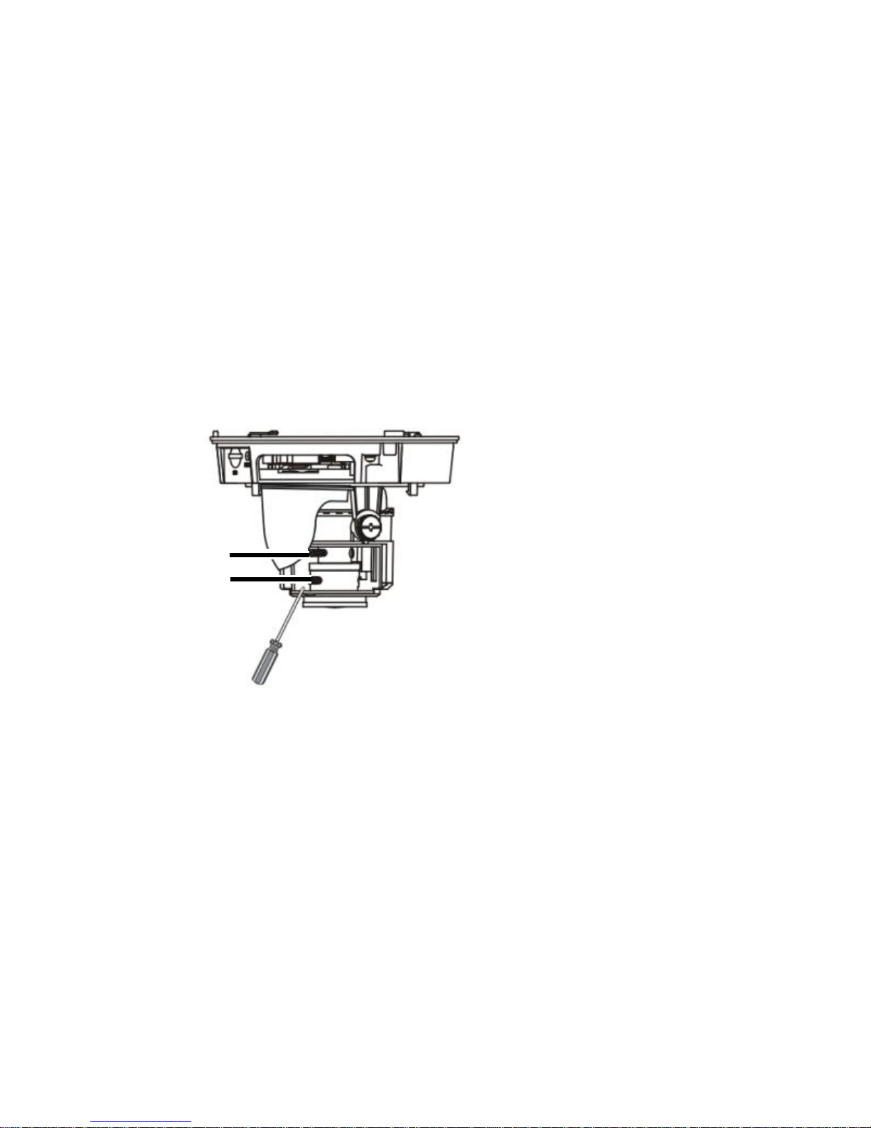
9. For a manual zoom lens camera, power on the camera and
adjust the manual zoom lens to get clear images.
a. Loosen the zooming and focusing knobs by using a
flathead screwdriver and adjust the knobs to obtain clear
images.
b. Then mount the dome bubble to complete the mounting.
10. For a motorized zoom lens camera, it will automatically
adjust the lens to present images.
Focusing knob
Zooming knob
Page 30

16
The preceding installation process is concealed
installation, during which holes are drilled in the ceiling
and the tail cable is led out from the top of the camera.
Cables are connected and frapped at the ceiling side to
prevent messy cables from affecting camera mounting.
If open installation is adopted, the tail cable is led out
from one side of the camera and can be routed from
one side where a piece of plastic skin is broken off.
After mounting the dome bubble, check that the three
socket fillister-head screws along the edge of the dome
bubble are tightened up to ensure that the camera is
properly sealed. For details, see Insert the Micro SD
Card (Optional).
In-Ceiling Mount
In-ceiling mount is usually used in indoors applications for
suspended ceilings. You need to purchase an in-ceiling bracket
separately for in-ceiling mount. For details about the bracket
model, see the recommended list provided by your dealer.
Before mounting your camera, please check:
Ensure that the space beyond the suspended ceiling is at
least 300 mm high, and the suspended ceiling is 10–40 mm
Page 31
17
thick. Otherwise, the in-ceiling bracket cannot be properly
mounted to the ceiling.
Ensure that the ceiling can bear the weight of the camera
and the in-ceiling bracket. Otherwise, it is recommended to
consolidate the ceiling by using a customized mounting kit.
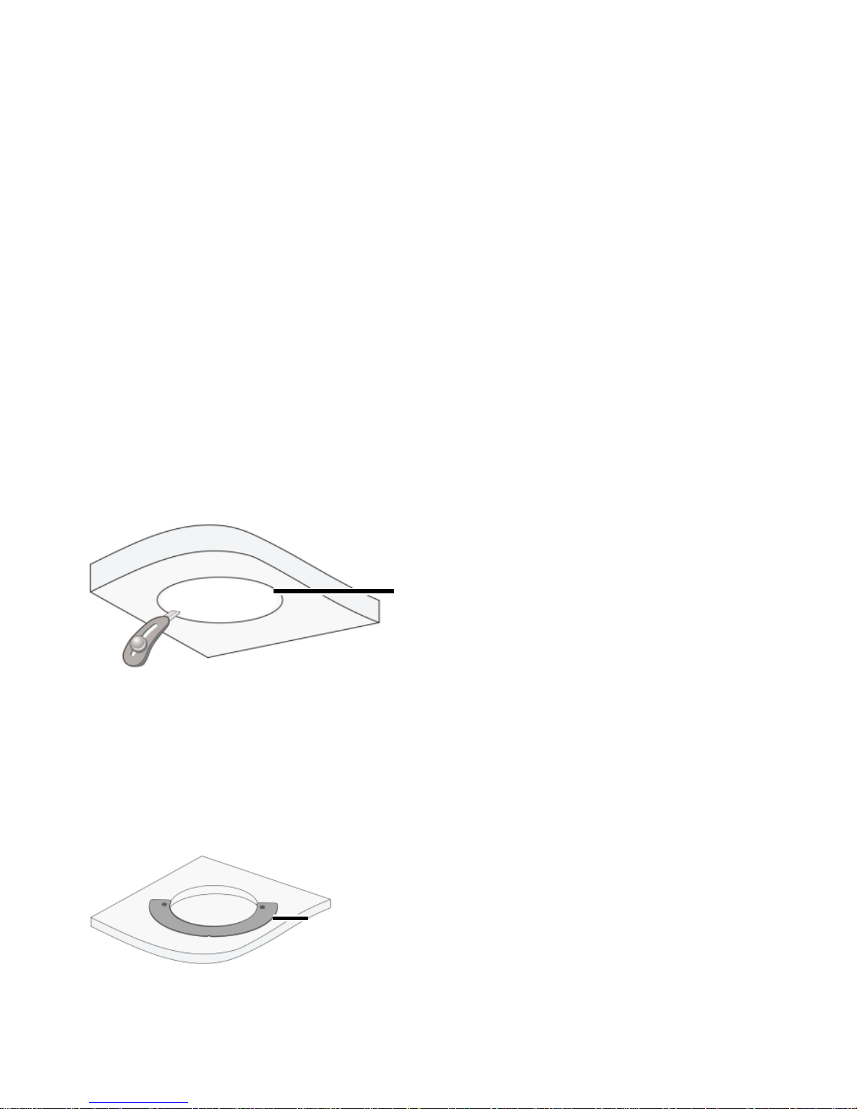
1. Drill holes in the ceiling.
Paste the hole positioning sticker of the in-ceiling bracket
onto the ceiling and drill a proper-sized hole in the ceiling.
2. Mount the inside bracket to the ceiling.
Put the inside bracket through the hole of the ceiling and
align the inner edge of the bracket with the edge of the hole.
Hole
positioning
sticker
Inside
bracket
Page 32
18
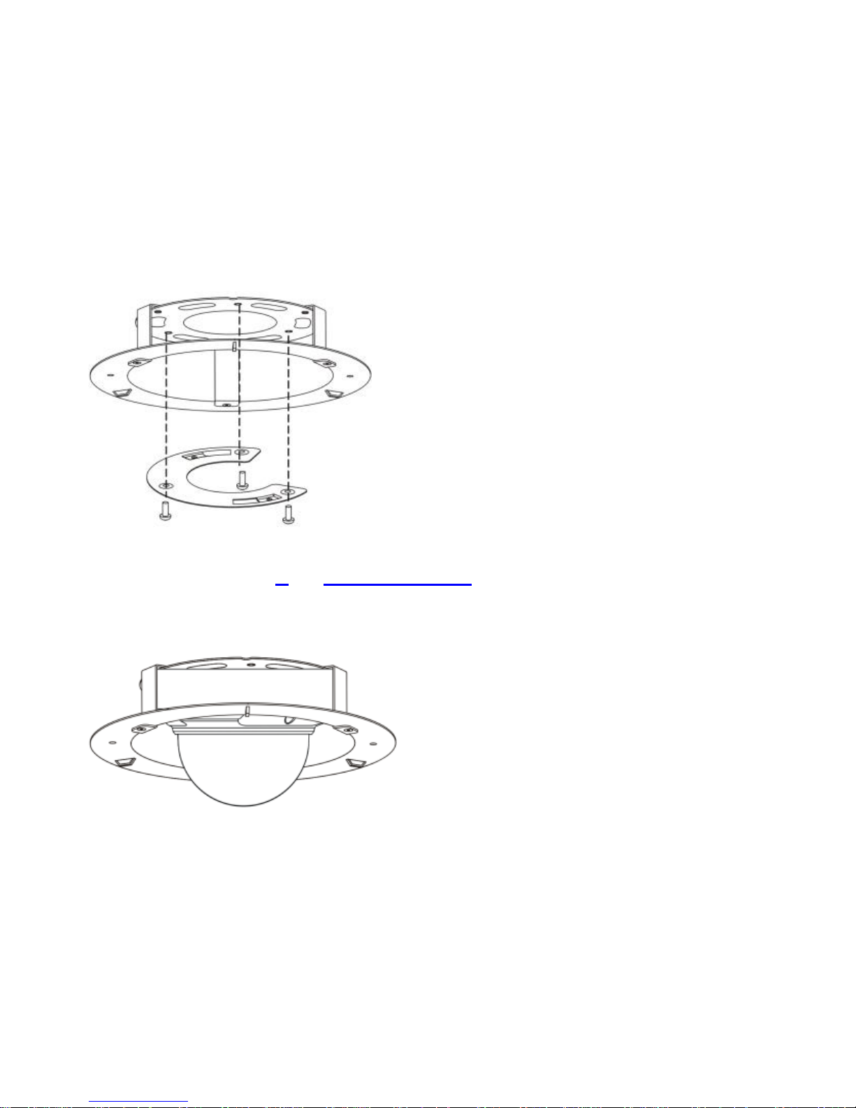
3. Fix the ceiling bracket to the in-ceiling bracket.
Lead three M4 screws through the ceiling bracket and the
in-ceiling bracket, and fix them by using a cross screwdriver.
4. Refer to step 5 of Ceiling Mount to mount the camera to the
ceiling bracket.
Page 33
19
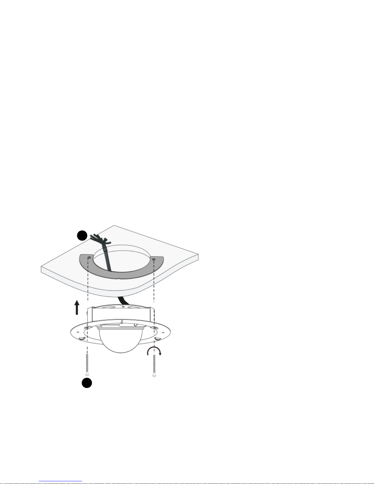
5. Mount the camera to the ceiling and fix the in-ceiling
bracket.
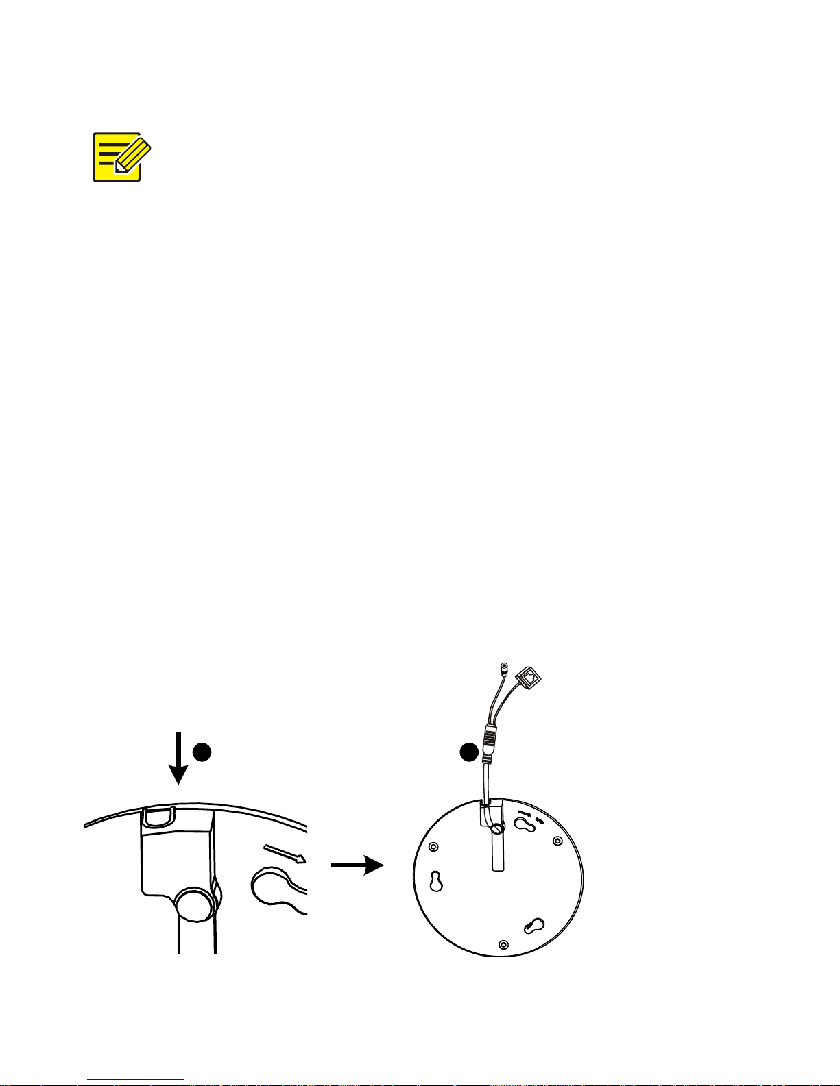
a. Connect all cables between the ceiling and the tail cable
of the camera, as shown by in the following figure.
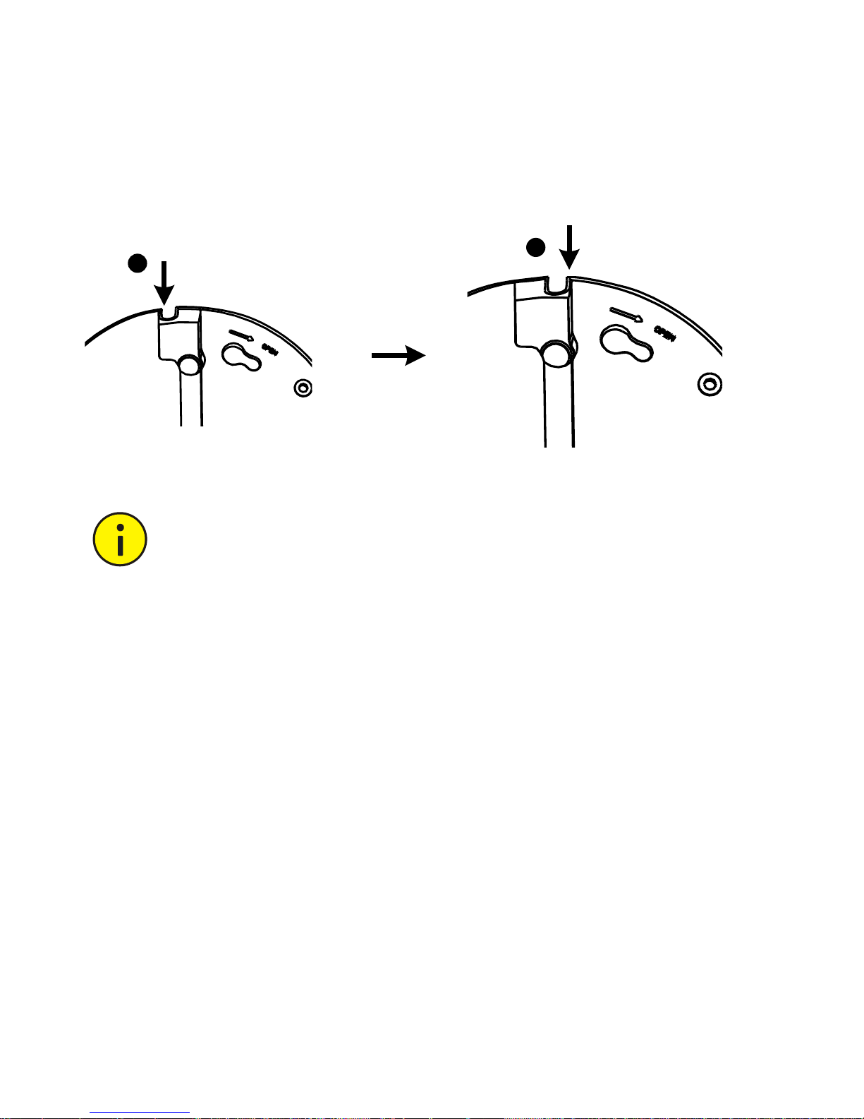
b. Slowly push the in-ceiling bracket holding the camera
towards the ceiling, align the screw holes of the inside
bracket, and then use a screwdriver to fix the in-ceiling
bracket, as shown by in the following figure.
1
2
Page 34
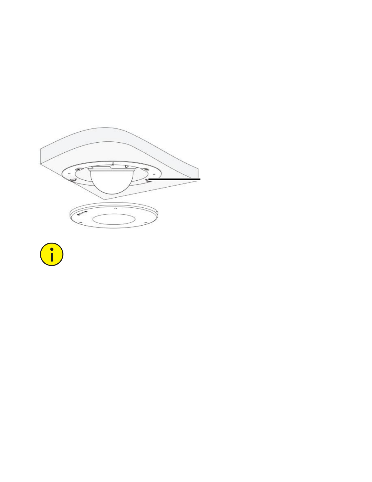
20
6. Mount a plastic panel to protect the camera.
Attach the plastic panel to the in-ceiling bracket and make
sure only the bubble is visible from outside.
Hold the camera to avoid drop of the camera when
tightening the bolts of the in-ceiling bracket.
Take cautions to avoid hurting fingers when attaching
the plastic panel.
Plastic Camera
Ceiling Mount
When mounting the camera on the wall or ceiling, ensure that
the wall or ceiling can hold self-tapping screws and bear the
weight of the camera.
Hook
Page 35
21
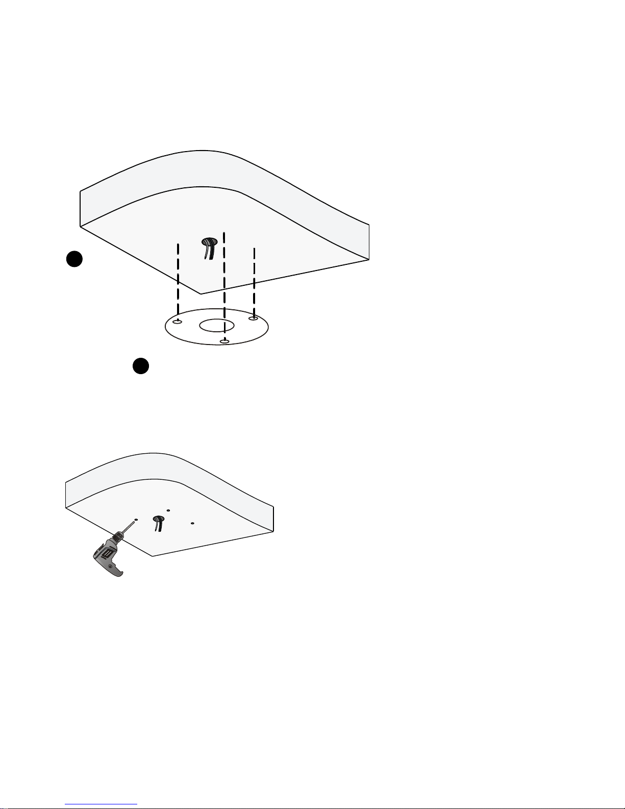
1. Position holes on the ceiling.
2. Drill holes according to drill template.
Lead cable out
of ceiling
2
Attach drill template to ceiling
1
Use a drill bit (6 mm or 6.5 mm) to
drill 30 mm-depth guide holes
Page 36
22
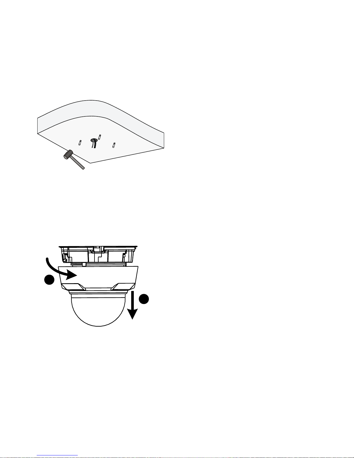
3. Knock in the plastic plugs and make sure they are tightened
in place.
4. Remove the dome bubble.
Loosen dome bubble in
“open”direction
1
2
Page 37
23
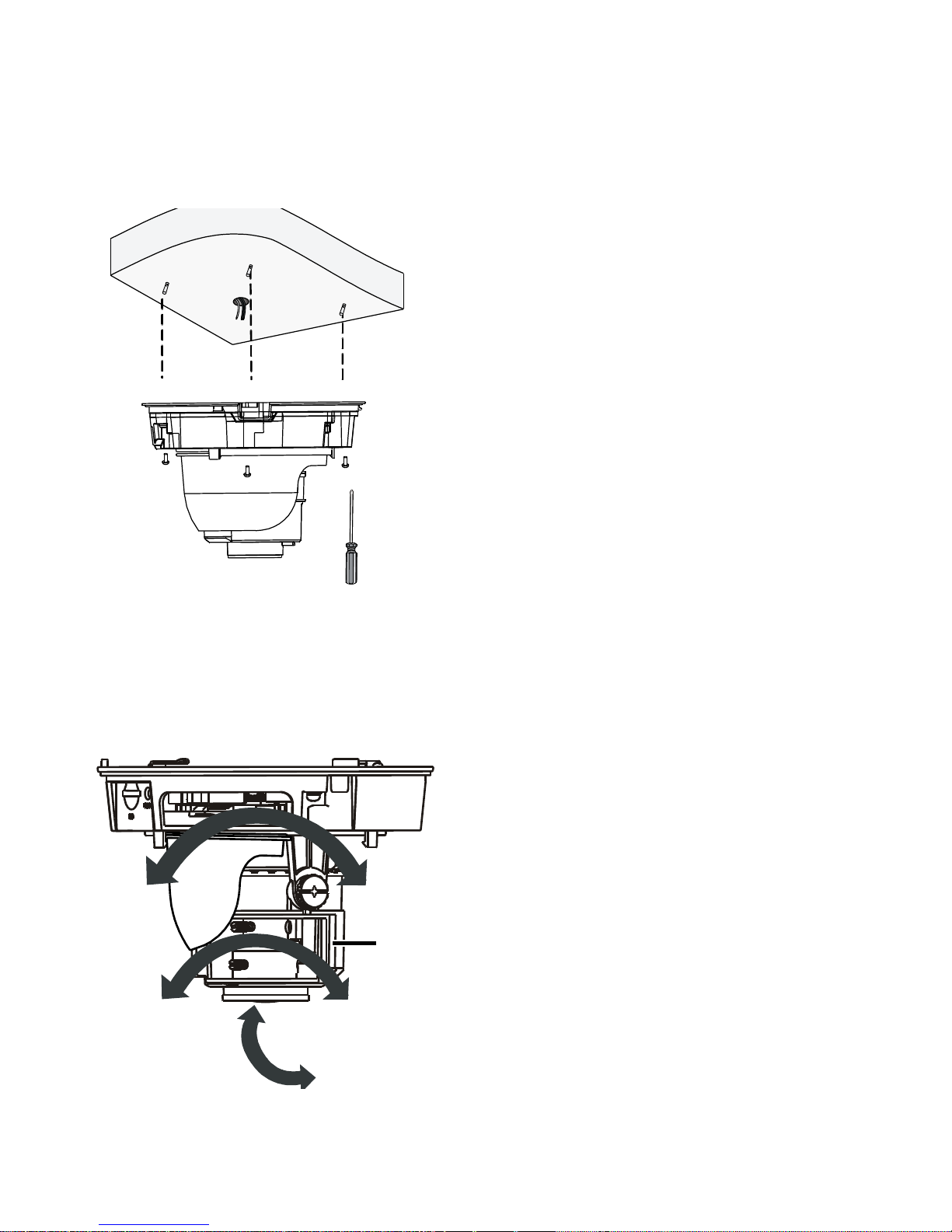
5. Mount the camera unit and connect the cables.
6. Adjust the monitoring direction.
Rotate dome horizontally
and vertically.
Dome unit
Page 38
24
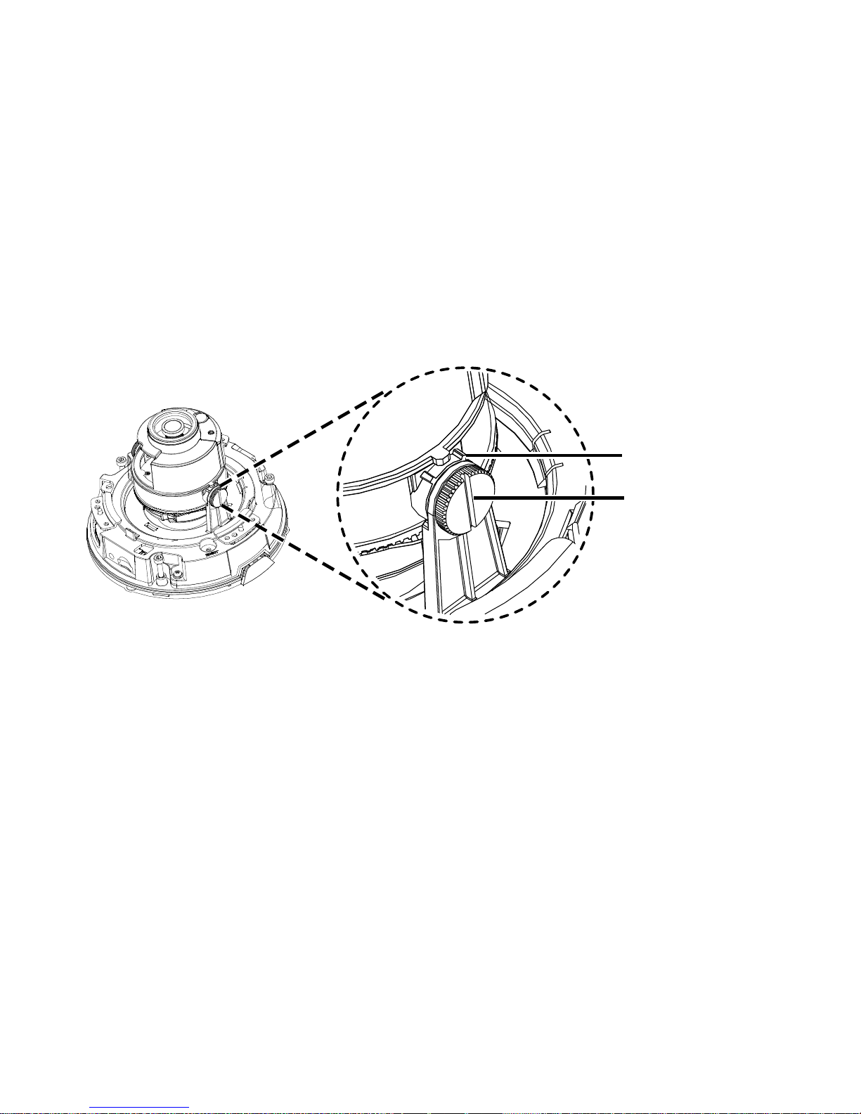
7. When you adjust the camera vertically, loosen the fixing
screws on both sides lightly, rotate the camera to the
desired monitoring direction and then fasten the screws.
Please stop rotating the camera when the spacing point is
blocked, otherwise the camera lens might be damaged.
Spacing Point
Screw
Page 39
25
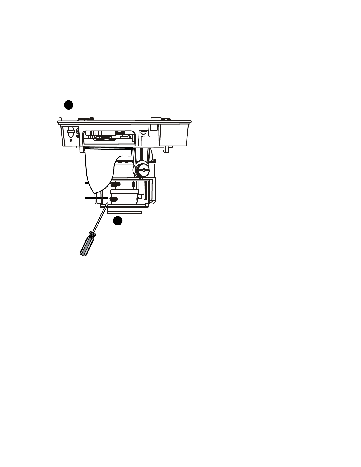
8. Connect the power. For a manual lens, adjust the lens until
you get a satisfying image.
9. Connect the power. For a motorized lens, adjust the lens
through Web interface.
2
Focusing knob
Loosen focus and zoom
buttons by using straight
screwdriver, and then
adjust buttons to get
clear image.
Replace dome bubble and
complete installation.
1
Zooming knob
Page 40
26
The preceding installation process is concealed
installation, during which holes are drilled in the ceiling
and the tail cable is led out from the top of the camera.
Cables are connected and frapped at the ceiling side to
prevent messy cables from affecting camera mounting.
If open installation is adopted, the tail cable is led out
from one side of the camera (remove a piece of plastic
skin from one side of camera by using a long nose plier
to route the cable).
Open Installation
Route the tail cable for open installation and mount the dome
bubble.
1. Route the tail cable for open installation.
Remove this piece of plastic skin
using long nose plier to make a
cable slot
1 2
Lead tail cables
out through
cable slot
Page 41
27
2. Mount the dome bubble.
Wall Mount
Take cautions not to drop the camera when replacing the
dome bubble. Rotate to secure the camera to the adapter
in the opposite direction after replacing the dome bubble.
Wall mount bracket and the adapter need to be purchased
separately. For details about the bracket model, see the
recommended list provided by your dealer.
1
Rotate dome bubble (opposite to “open"
direction) till it clicks into position.
2
Lock into position.
Page 42
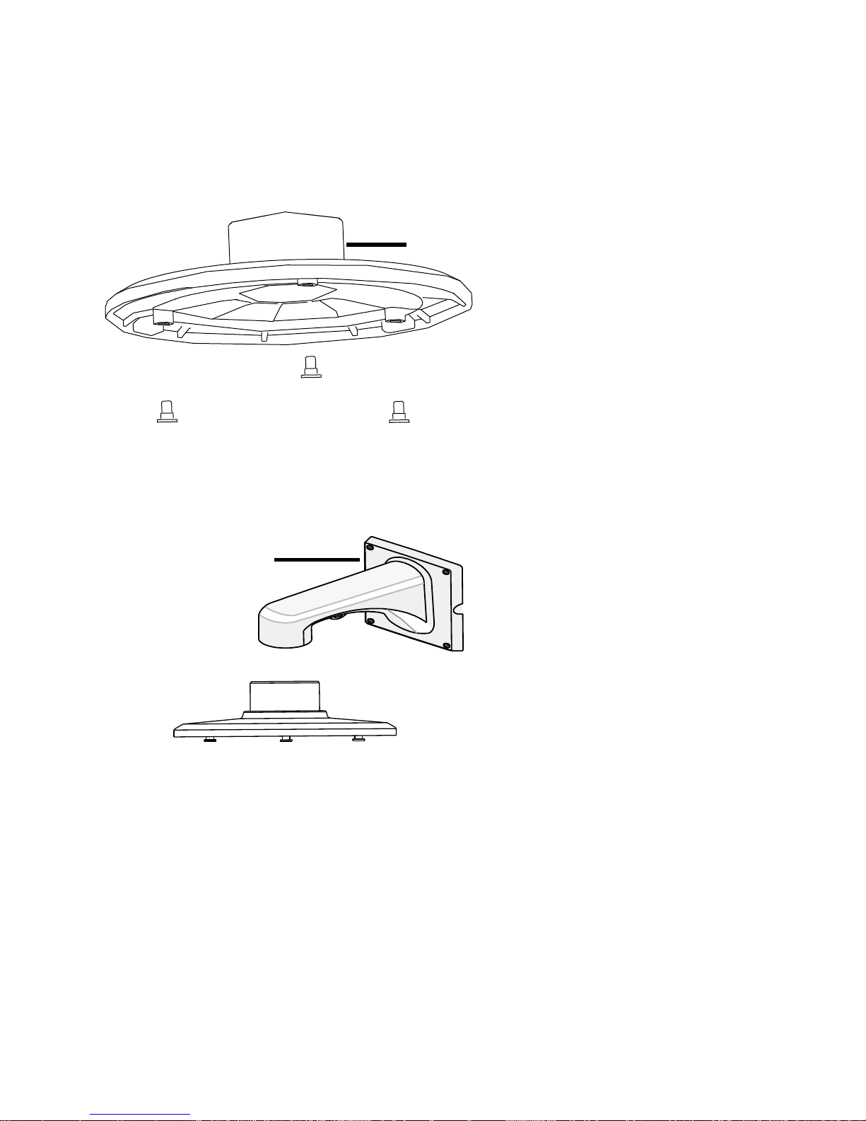
28
1. Secure screws to the adapter.
2. Attach the adapter to the mounting bracket.
Adapter
Mounting bracket
Page 43
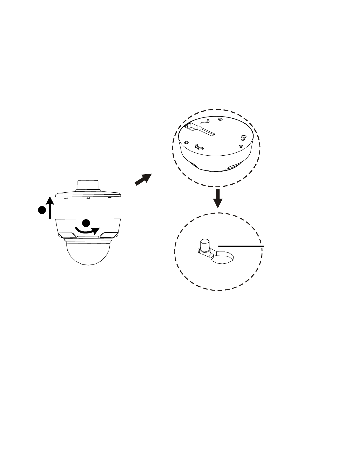
29
3. Secure the camera unit to the adapter and connect the
cables.
1
2
Lock into position
Page 44
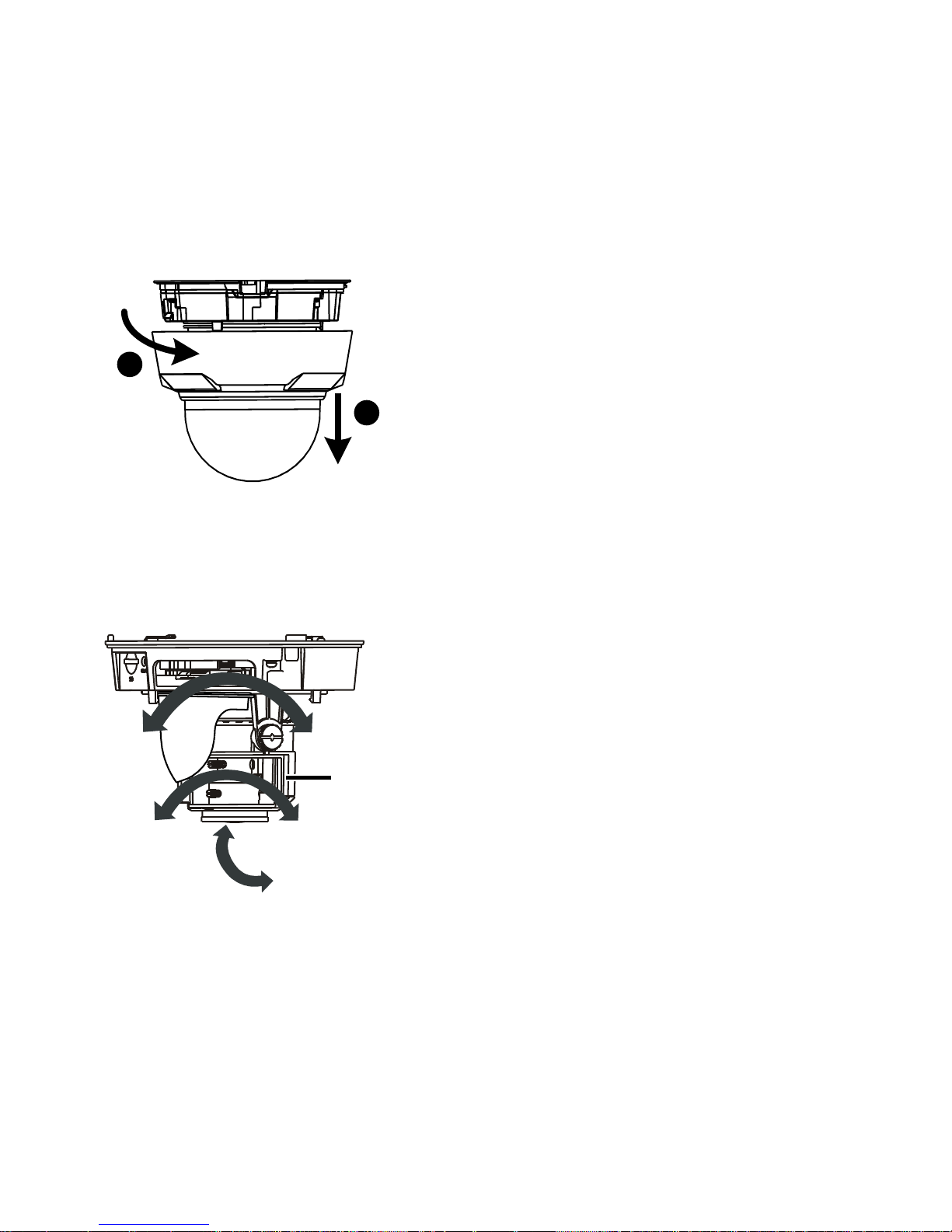
30
4. Remove the dome bubble.
5. Adjust the monitoring direction.
Loosen dome bubble in
“open”direction
1
2
Turn the lens vertically and
horizontally
Dome
Page 45
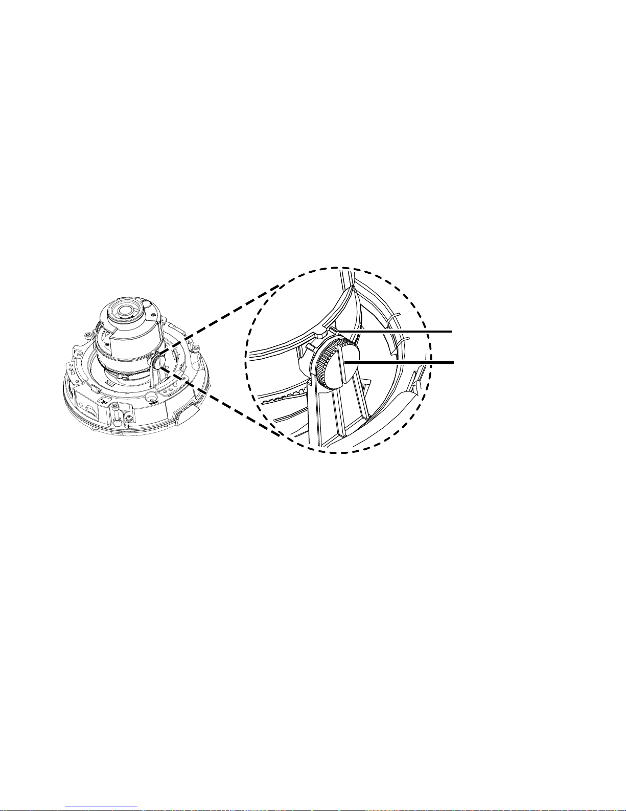
31
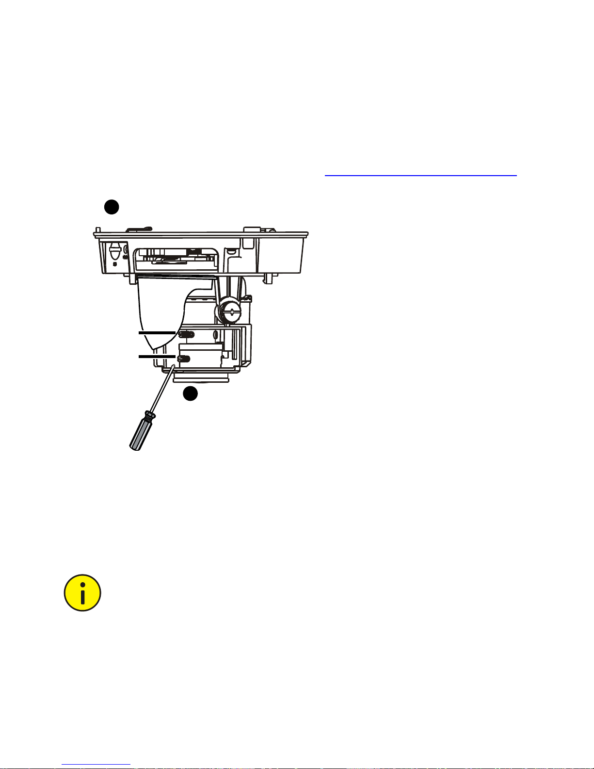
6. When you adjust the camera vertically, loosen the fixing
screws on both sides lightly, rotate the camera to the
desired monitoring direction and then fasten the screws.
Please stop rotating the camera when the spacing point is
blocked, otherwise the camera lens might be damaged.
Spacing Point
Screw
Page 46
32
7. For manual lens, power on the device, and then turn the
rotate knob to get clear image. For more information about
replacing the dome bubble, see Replace the dome bubble.
8. For automatic lens, you can adjust the image directly after
power on the device.
In-ceiling Mount
Take cautions not to drop the camera when replacing the
dome bubble. Rotate to secure the camera to the adapter
in the opposite direction after replacing the dome bubble.
Zooming knob
Focusing knob
Loosen focus and zoom
buttons by using straight
screwdriver, and then
adjust buttons to get
clear image
Replace dome bubble and
complete installation
1
2
Page 47

33
In-ceiling mount is usually adopted in indoors mounting for
suspended ceiling structure. Mount bracket needs to be
purchased separately. For details about the bracket model, see
the recommended list provided by your dealer.
Check before installation:
Ensure that the space beyond the suspended ceiling is at
least 300 mm high, and the suspended ceiling is 10–40 mm
thick. Otherwise, the in-ceiling bracket cannot be properly
mounted to the ceiling.
Ensure that the ceiling can bear the weight of the camera
and the in-ceiling bracket. Otherwise, it is recommended to
consolidate the ceiling by using a customized mounting kit.
Steps:
Page 48
34
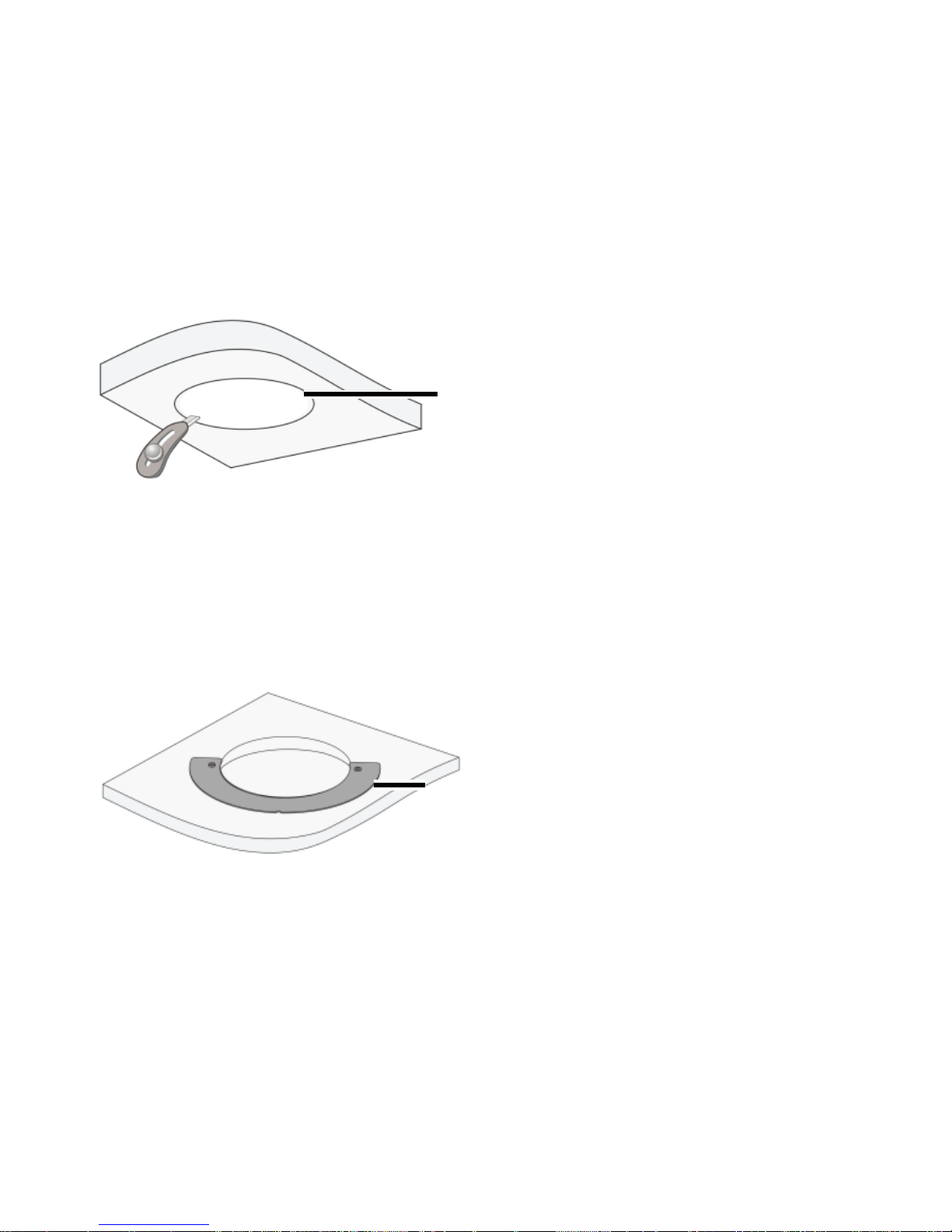
1. Drill holes in the ceiling.
Paste the hole positioning sticker of the in-ceiling bracket
onto the ceiling and drill a proper-sized hole in the ceiling.
2. Mount the inside bracket to the ceiling.
Put the inside bracket through the hole of the ceiling and
align the inner edge of the bracket with the edge of the hole.
Hole
positioning
sticker
Inside
bracket
Page 49
35
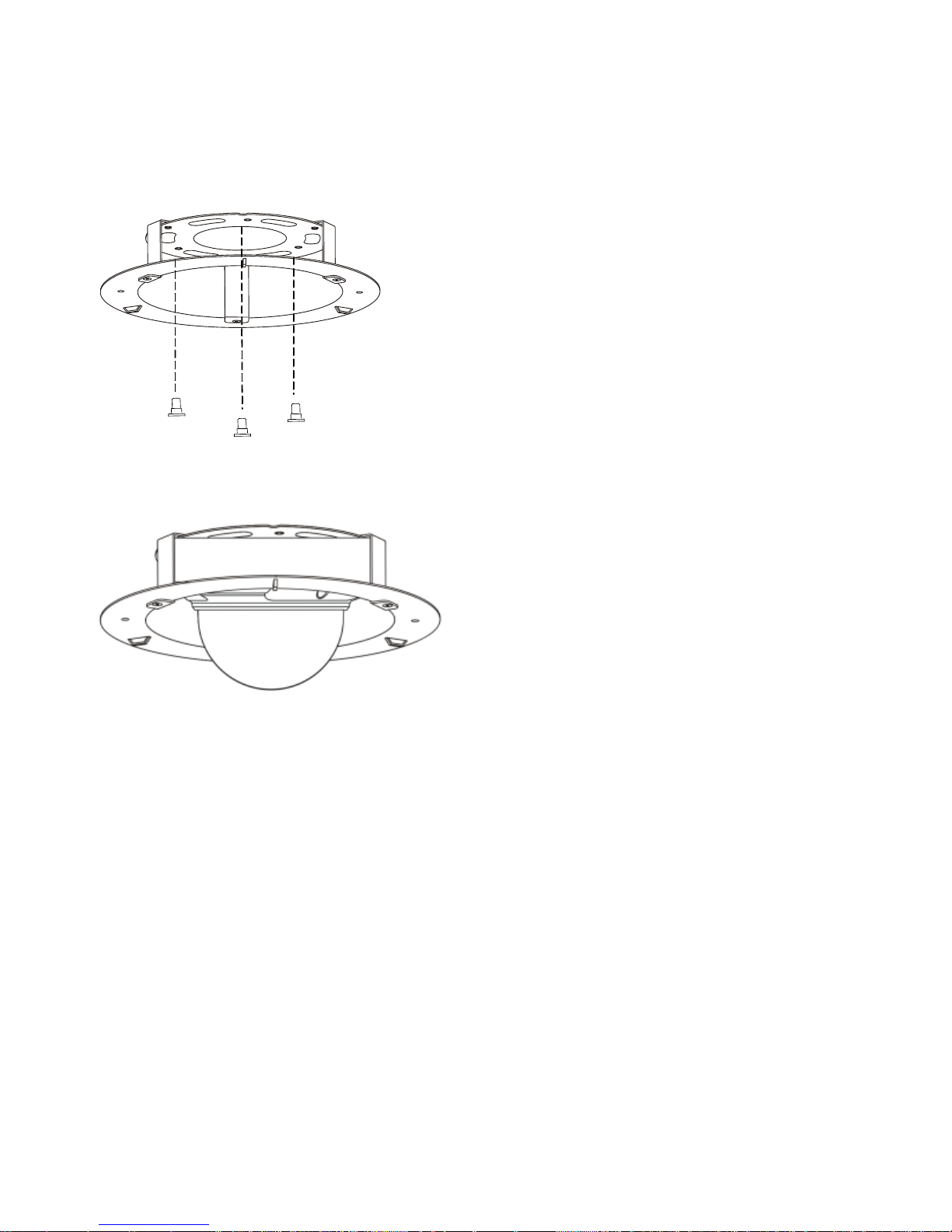
3. Fix the screws to the in-ceiling bracket.
4. Rotate to mount the camera to the ceiling bracket.
Page 50
36
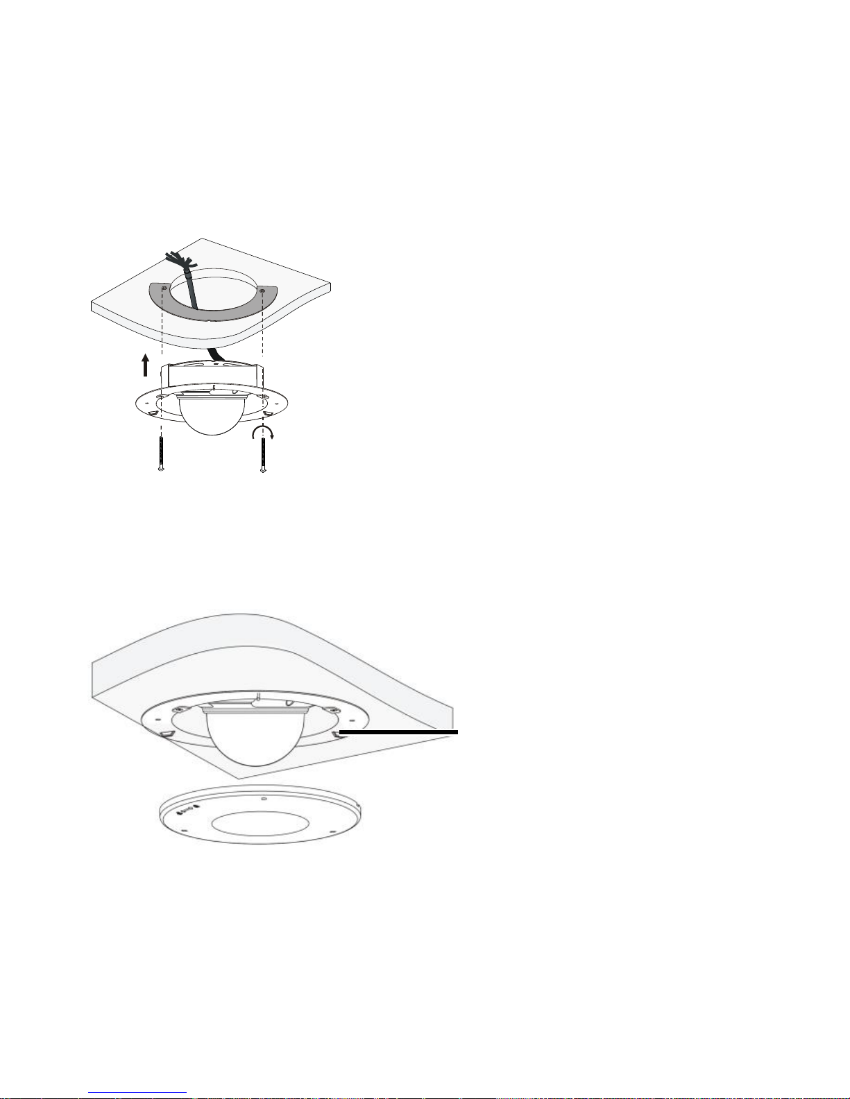
5. Mount the camera to the ceiling and fix the in-ceiling
bracket.
6. Mount a plastic panel to protect the camera.
Turn to lock the hook in the plastic panel into the buckle.
Hook
Page 51

37
Start the Camera
After verifying that the camera is properly mounted, connect one
end of the power adapter to the mains and connect the other
end to the power interface. At this time, the system status
indicator lights (see Camera Structure). When the indicator turns
green, the camera has been successfully started.
Reset the Camera to Default Settings
Remove the dome bubble first. For the detailed steps, see the
first step in Insert the Micro SD Card (Optional). Press and hold
the Reset button in the bottom (as shown in Figure 1) for about
15 seconds till the system status indicator turns red. The Reset
button only works within ten minutes after the camera is
powered on. Then the camera is restored to the default settings
after the startup.
Page 52
38
Waterproof Measures
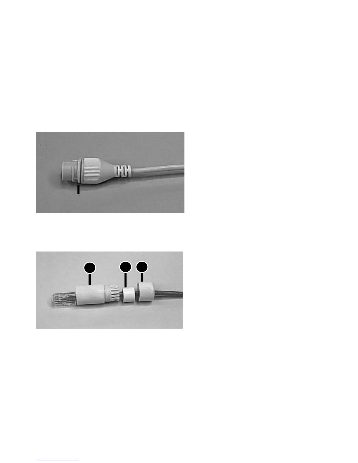
Waterproof Components for an RJ45 Plug
1. Attach the seal ring to the copper interface.
2. Mount the waterproof components.
Seal ring
12
3
Insert in order
Page 53
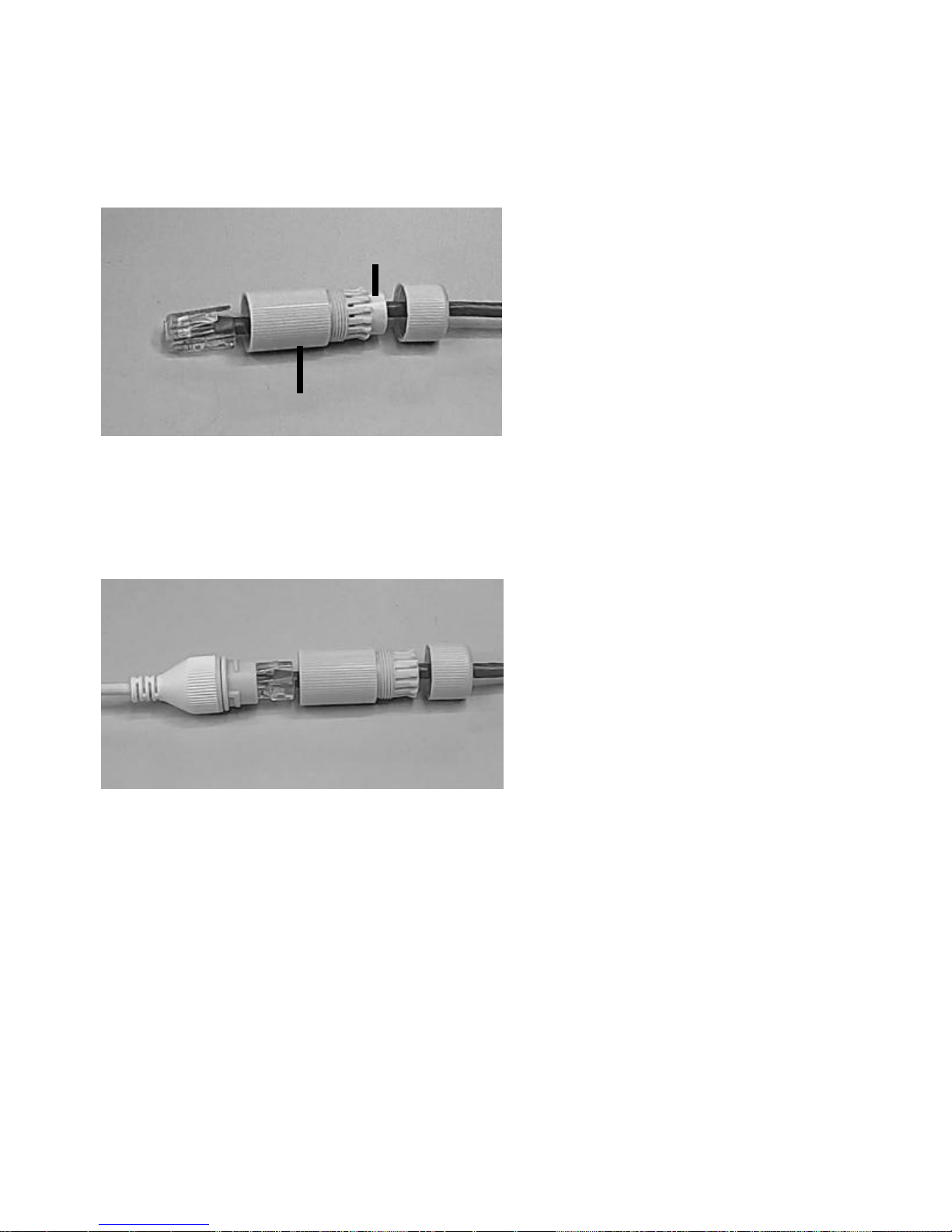
39
3. Insert the cylindrical waterproof ring into bolt.
4. Insert the cable into the Ethernet copper interface and screw
the waterproof bolt in.
Cylindrical waterproof ring
Waterproof bolt
Page 54
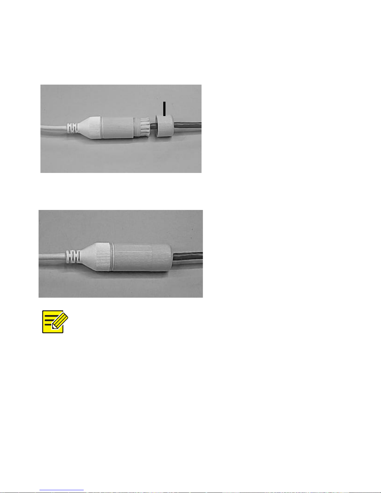
40
5. Screw in the waterproof bolt lid.
6. Finish the waterproof installation.
You can crimp the inner wires of the cable with the RJ45
plug first and then cover the waterproof components or
cover the waterproof components first.
Bolt lid
Page 55
41
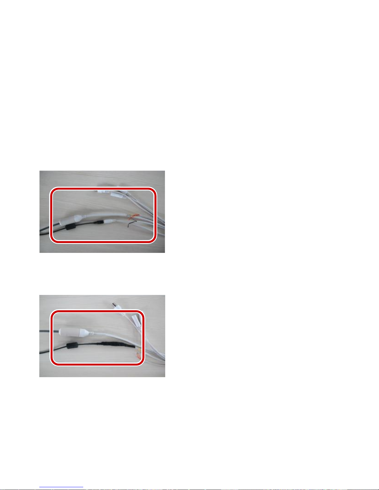
Waterproof Tail Cable
Connect the tail cables and then take the following steps to
protect the tail cables from water using waterproof tapes. The
following figures are for your reference only.
1. Connect the tail cables.
2. Protect the connected cables using insulating tapes.
Page 56
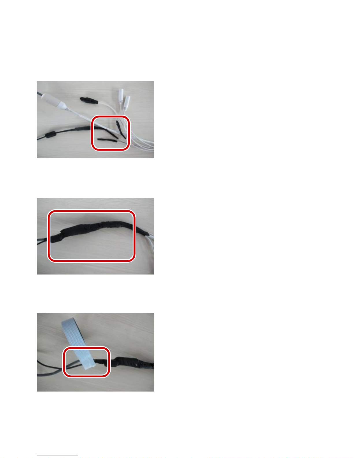
42
3. Protect other cables using insulating tapes.
4. Wrap all the tail cables together using insulating tapes.
5. Choose a start point for waterproof tapes.
Waterproof tape
Page 57
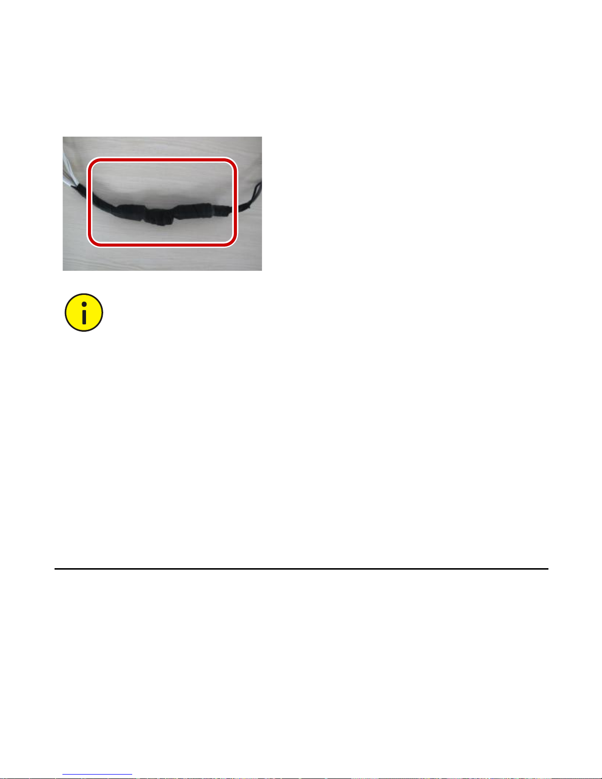
43
6. Protect the tail cables using waterproof tapes.
Avoid short circuit when insulating the cables.
Use self adhesive waterproof tapes that will stick
together with the twisted cables.
Tighten waterproof tapes when wrapping the cables
and make sure the cable connections are fully covered.
You are recommended to put the waterproof cables in
a waterproof junction box which needs to be purchased
separately.
3 Set Your Camera over the LAN
To view and configure your camera via the LAN (Local Area
Network), you need to install the EZStation to find your camera
and change its IP address.
Page 58
44
Please contact your dealer to get the EZStation
software.
Please refer to the user manual of EZStation for
detailed information.
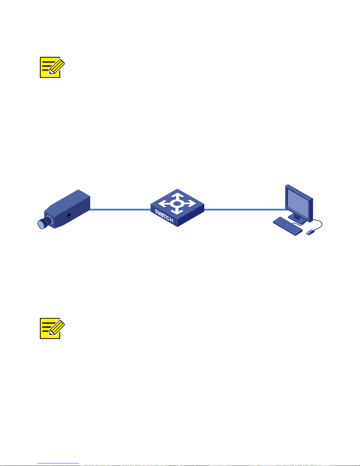
1. Connect your camera and your PC as shown in the figure
below to ensure the routing is available.
2. Use EZStation to search online cameras automatically.
3. Modify your camera settings if necessary, including its IP
address and subnet mask.
The default IP address is “192.168.0.13”. The default
username is “admin” and the default password is
“123456”.
To access your camera from a different subnet, set the
gateway for your camera after you log in.
Page 59
45
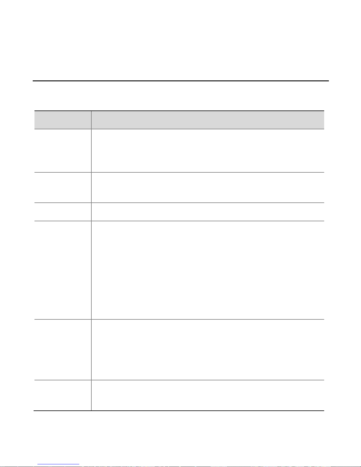
4 Access Your Camera
System Requirements for Your PC
Item
Requirements
Operating
system
Microsoft Windows8/Windows7/Windows XP
(32-bit or 64-bit). Microsoft Windows7 is
recommended.
CPU
2.0GHz or higher, dual-core. Intel i3 CPU or above is
recommended.
Memory
At least 1GB. 2GB (or higher) is recommended.
Graphic
card
At least 128MB display memory. Mainstream
discrete graphics with more than 1GB display
memory are recommended. The hardware should
support DirectX9.0c.
Note:
Make sure that the latest driver is installed on
graphic card.
Sound
card
Required.
Note:
Two-way audio and voice broadcast require the
latest driver on sound card.
Network
card
Megabit Ethernet network cards (or higher) are
recommended.
Page 60

46
Access Your Camera
Before you begin, check that:
Your camera is operating properly and connected to the
network.
The PC you are using is installed with Internet Explorer 7.0 or
later. IE 8.0 is recommended.
Follow these steps to access your camera through the Web
interface:
1. Open your browser, input the IP address of your camera
(default IP is 192.168.0.13) in the address bar and then press
Enter to open the login page.
2. Enter the username (default is “admin”) and password
(default is “123456”) and then click Login.
Install the ActiveX at your first login. For the detailed steps,
see Install the ActiveX. When the installation of the ActiveX
is completed, open your IE to log in.
Page 61
47
Install the ActiveX
The following takes the IE browser as an example to describe the
installation steps.
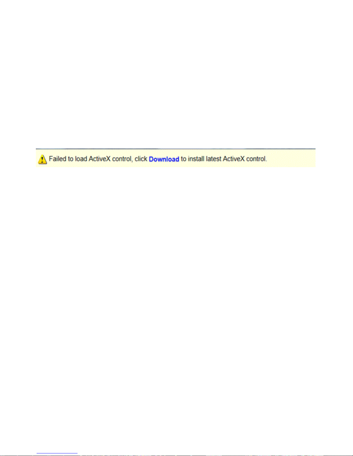
1. Click Download.
2. Click Run to install the downloaded ActiveX. You may also click
Save to download the file to your computer first.
Page 62

48
For your first login with Windows 7, if the system does
not prompt you to install ActiveX, follow these steps to
turn off UAC: click the Start button, and then click
Control Panel. In the search box, type uac, and then
click Change User Account Control Settings. Move the
slider to the Never Notify position, and then click OK.
After UAC is turned off, log in again.
If the installation failed, open Internet Option in IE
before login. Click the Security tab, click Trusted sites,
and then click Sites to add the website. If you use
Windows 7, you need to save the setup.exe to your PC
first, and then right-click the file, select Run as
administrator, and then install it according to
instructions.
Adjust the Display
For manual lens, uncover the dome bubble, and then turn the
lens to adjust the zoom and focus. For motorized zoom lens, click
the Zoom and Focus buttons on the Web page.
Page 63

49
You can also connect the local video output interface on
your camera to your monitor. When video is displayed on
your monitor, adjust the zoom and focus of your camera
while watching the display till you get a satisfying display.
Page 64

BOM: 3101C0BQ
 Loading...