

Page 1

Digital Video Servers
Quick Guide
Manual Version: V1.00
Page 2

Thank you for purchasing our product. If there are any questions, or
requests, please do not hesitate to contact the dealer.
Copyright
Copyright 2015 Zhejiang Uniview Technologies Co., Ltd. All rights
reserved. No part of this manual may be copied, reproduced, translated,
or distributed in any form or by any means without prior consent in
writing from our company.
Trademark Acknowledgement
and other Uniview’s trademarks and logos are the property of
Zhejiang Uniview Technologies Co., Ltd. Other trademarks, company
names and product names contained in this manual are the property of
their respective owners.
Disclaimer
CAUTION!
The default password is used for your first login. To ensure account
security, please change the password after your first login. You are
recommended to set a strong password (no less than eight characters).
To the maximum extent permitted by applicable law, the product
described, with its hardware, software, firmware and documents, is
provided on an "as is" basis.
Best effort has been made to verify the integrity and correctness of
the contents in this manual, but no statement, information, or
recommendation in this manual shall constitute formal guarantee
of any kind, expressed or implied. We shall not be held responsible
for any technical or typographical errors in this manual. The
Page 3

contents of this manual are subject to change without prior notice.
Update will be added to the new version of this manual.
Use of this manual and the product and the subsequent result shall
be entirely on the user's own responsibility. In no event shall we be
reliable to you for any special, consequential, incidental, or indirect
damages, including, among others, damages for loss of business
profits, business interruption, or loss of data or documentation, or
product malfunction or information leakage caused by cyber attack,
hacking or virus in connection with the use of this product.
Video and audio surveillance can be regulated by laws that vary
from country to country. Check the law in your local region before
using this product for surveillance purposes. We shall not be held
responsible for any consequences resulting from illegal operations
of the device.
The illustrations in this manual are for reference only and may vary
depending on the version or model. The screenshots in this manual
may have been customized to meet specific requirements and user
preferences. As a result, some of the examples and functions
featured may differ from those displayed on your monitor.
This manual is a guide for multiple product models and so it is not
intended for any specific product.
Due to uncertainties such as physical environment, discrepancy
may exist between the actual values and reference values provided
in this manual. The ultimate right to interpretation resides in our
company.
Environmental Protection
This product has been designed to comply with the requirements on
environmental protection. For the proper storage, use and disposal of
this product, national laws and regulations must be observed.
Page 4

Safety and Compliance Information
Safety Symbols
The symbols in the following table may be found on installation-related
equipment. Be aware of the situations indicated and take necessary
safety precautions during equipment installation and maintenance.
Symbol
Description
Generic alarm symbol: To suggest a general safety
concern.
ESD protection symbol: To suggest
electrostatic-sensitive equipment.
Electric shock symbol: To suggest a danger of high
voltage.
The symbols in the following table may be found in this manual.
Carefully follow the instructions indicated by the symbols to avoid
hazardous situations and use the product properly.
Symbol
Description
WARNING!
Indicates a hazardous situation which, if not
avoided, could result in bodily injury or death.
CAUTION!
Indicates a situation which, if not avoided, could
result in damage, data loss or malfunction to
product.
NOTE!
Indicates useful or supplemental information
about the use of product.
Safety Information
Installation and removal of the unit and its accessories must be carried
out by qualified personnel. Please read all of the safety instructions
below before installation and operation.
Page 5

This device is a class A product and may cause radio interference.
Take measures if necessary.
While shipping, the device should be packed in its original packing.
Verify that installation is correct. Incorrect cable connection may
cause personal injury or device damage.
The installation must be made by qualified personnel and should
conform to all the local codes.
If the product does not work properly, please contact your dealer.
Never attempt to disassemble the device yourself. We shall not
assume any responsibility for problems caused by unauthorized
repair or maintenance.
Ensure a proper operating environment, including temperature,
humidity, ventilation and power supply. Make sure the device is
properly grounded and the lightning protection meets
requirements. Keep the device from moisture, dust, strong
electromagnetic radiation and vibration.
Power down the device before connecting and disconnecting
accessories and peripherals.
Protect the power cable from being stepped on or pressed,
particularly at the plug, receptacle, and the part leading out of the
device.
Strictly follow the procedure to shut down the device. Sudden
power failures can cause disk damage and functional abnormalities.
In an environment where power supply is frequently interrupted,
use an Uninterrupted Power Supply (UPS).
Improper use or replacement of the battery may result in hazard of
explosion. Use the manufacturer recommended battery.
Take necessary measures to ensure data security and protect the
device from network attack and hacking (when connected to
Internet). Possible risks and consequences are at user's sole
discretion.
Page 6

WARNING!
Never look at the transmit laser while the power is on. Never look
directly at the fiber ports and the fiber cable ends when they are
powered on.
Use of controls or adjustments to the performance or procedures
other than those specified herein may result in hazardous laser
emissions.
Regulatory Compliance
FCC Part 15
This equipment has been tested and found to comply with the limits for
digital device, pursuant to part 15 of the FCC Rules. These limits are
designed to provide reasonable protection against harmful interference
when the equipment is operated in a commercial environment. This
equipment generates, uses, and can radiate radio frequency energy and,
if not installed and used in accordance with the instruction manual, may
cause harmful interference to radio communications. Operation of this
equipment in a residential area is likely to cause harmful interference in
which case the user will be required to correct the interference at his
own expense.
This product complies with Part 15 of the FCC Rules. Operation is subject
to the following two conditions:
1. This device may not cause harmful interference.
2. This device must accept any interference received, including
interference that may cause undesired operation.
Page 7

LVD/EMC Directive
This product complies with the European Low Voltage Directive
2006/95/EC and EMC Directive 2004/108/EC.
WEEE Directive–2002/96/EC
The product this manual refers to is covered by the Waste Electrical &
Electronic Equipment (WEEE) Directive and must be disposed of in a
responsible manner.
Page 8

i
Contents
1 Introduction ......................................................................................... 1
Front Panel .................................................................................................... 1
Back Panel ..................................................................................................... 3
2 Mount .................................................................................................. 4
Preparation ................................................................................................... 4
Mounting a 4-channel DVS ........................................................................... 5
Mount in a Protective Box .................................................................... 5
Mount in a Cabinet ............................................................................... 6
Cable Connection .................................................................................. 7
Mounting a 16-channel DVS ....................................................................... 10
Mount in a Protective Box .................................................................. 10
Mount on a Workbench ..................................................................... 12
Cable Connection ................................................................................ 12
AC Power Cable Connection ............................................................... 16
Mount Verification ...................................................................................... 17
Starting the Device ...................................................................................... 17
3 Login to the Web Interface .................................................................. 17
Page 9

1
1 Introduction
The Digital Video Server (DVS) is a new generation network video
surveillance media terminal integrated with functions to encode,
compress and transmit audio and video data. The DVS can capture
images and sounds from a remote site and finds application in city
surveillance, transportation, banking and finance, power industry and
healthcare. Please refer to the datasheet for detailed specifications.
This manual mainly describes the device hardware and the installation
procedure. It also describes how to access the Web interface of the
device.
Front Panel
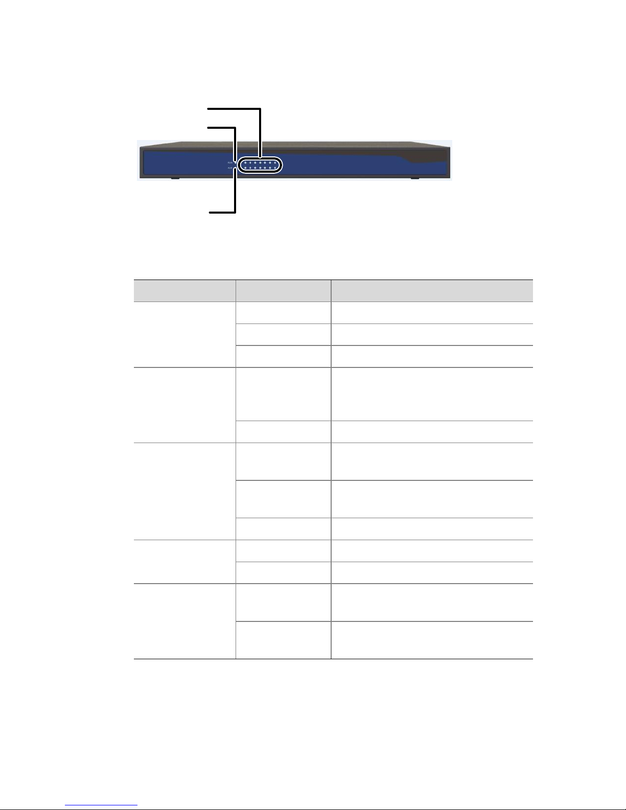
Figure 1-1 4-channel DVS
RUN LED
ENC LED
ACT LED
Network
LINK LED
RS485/422
RS232
USB
RST button
ALM LED
Blank panel for adapters
Page 10
2
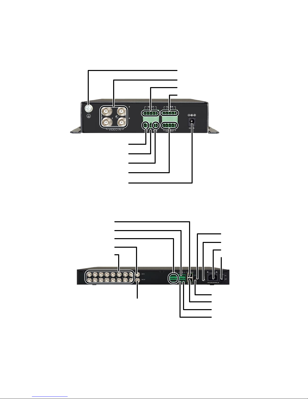
Figure 1-2 16-channel DVS
Table 1-1 LED Status Description
LED
Status
Indication
RUN (operation)
Blinks green
The device is starting up.
Steady green
The device is operating.
Off
The device is shut down.
ALM (alarm)
Steady red
A device alarm, for example,
temperature alarm, has been
raised.
Off
No device alarm has been raised.
ENC (encoding)
Steady green
The device is receiving signals but
is not encoding.
Blinks green
The device is receiving and
encoding signals.
Off
No signal input.
ACT (data
transmission)
Blinks yellow
Data is being transmitted.
Off
No data transmission.
LINK (network
connection)
Steady green
The device is connected to
network.
Off
The device is disconnected from
network.
RUN LED
ENC LED
ALM LED
Page 11
3
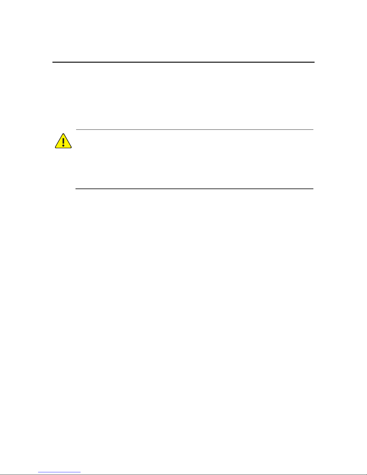
Back Panel
Figure 1-3 4-channel DVS
Figure 1-4 16-channel DVS
Alarm input
Audio input
Grounding
Video input
Two-way audio
RS485
Alarm output
DC input
Grounding
Video input
Audio input
Alarm input
Two-way audio (input)
Network
Power on/off
Power input
Grounding
RST button
Two-way audio (output)
USB
RS232/RS485
Alarm output
Grounding
Page 12
4
2 Mount
Preparation
Check the package
Check against the packing list to verify that the device model is correct
and all items are included.
WARNING!
Do not remove the seal on the device by yourself. Contact your dealer if
you need assistance. The manufacturer and dealer do not assume
responsibility if the device has been subject to faulty or improper
installation, maintenance or repair by user.
Check the installation site
For outdoor installations, the device must be secured in a protective box
and properly grounded. The following requirements must be met for
both outdoor and indoor installations:
The power, audio/video and RS485 interfaces should be protected
by appropriate lightning protection devices.
The device is correctly grounded. Please refer to the DVS_DC Cable
Connection Guide for details.
Route cables
The power cable should be routed separately from other cables such as
the network cable, video and audio cables. Use cable fasteners for
cables that are too long. Tag the cables for easy identification.
If the device is installed in a standard 19-inch cabinet, cables should be
routed appropriately on top or at the bottom, depending on the way
signal cables are routed in the server room.
Page 13
5
CAUTION!
Make sure the device is disconnected from power before starting
cable connection.
Choose cables that meet specifications. For detailed information,
please refer to the DVS_DC Cable Connection Guide.
Fix cables at an appropriate position close to the device but away
from the air vents. Allow appropriate strain relief.
Mounting a 4-channel DVS
Mount in a Protective Box
NOTE!
The protective box should meet specified requirements. Please refer to
the DVS_DC Cable Connection Guide for details.
Horizontal mount
Place the device horizontally if the protective box is placed on the
ground.
Wall mount
Place the device vertically in the wall-mount protective box. The air
vents on two sides should be facing upward and downward.
Use screws to secure the device in the protective box. Allow at least
10cm of space above and below the device inside the protective box for
ventilation.
Page 14
6
Mount in a Cabinet
NOTE!
Use a 19-inch cabinet firm enough to hold the device. This section
takes a standard 19-inch cabinet as an example.
Before you start, make sure the cabinet is stabilized and grounded
properly, and no object is left inside the cabinet or placed nearby
to hinder the mount.
Frame mount
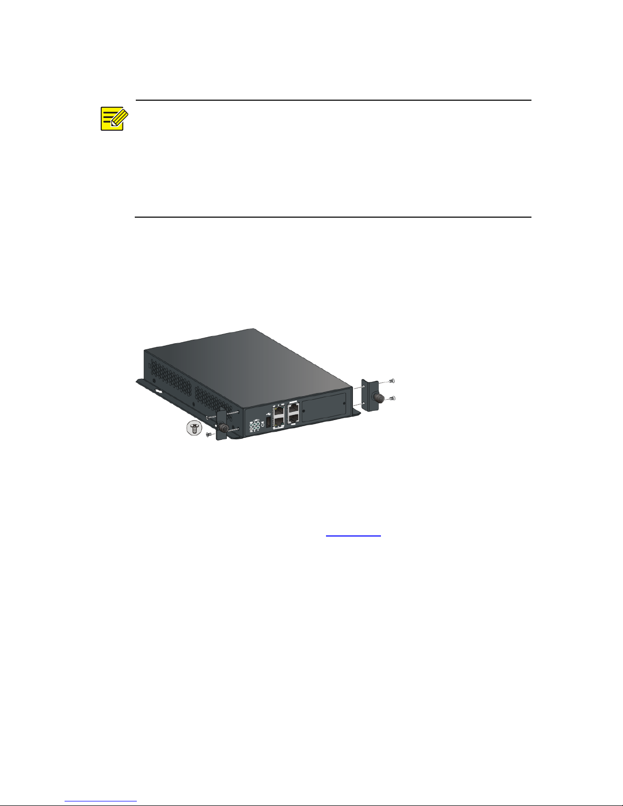
1. Install the mounting ears as shown in the figure below.
Figure 2-1 Installing Mounting Ears
2. Mount the device to a frame in the cabinet. For detailed steps,
please refer to the Video Encoder/Decoder Frame Quick Guide.
Holder mount
1. Install the mounting ears. See Figure 2-1.
2. Mount the device to a holder in the cabinet. For the detailed steps,
please refer to the 1U DVS/DC Holder Installation Guide.
Mount without frame or holder
To mount without using a frame or holder, secure the device in the
cabinet as appropriate and leave sufficient room on both sides for heat
dissipation. Do not place any objects on the device.
Page 15
7
Cable Connection
CAUTION!
Disconnect the device from power before connecting cables.
Use cables that meet specifications. Refer to the DVS_DC Cable
Connection Guide for details.
Connect peripherals as needed. For connection instructions, refer to the
documentation for the corresponding peripherals.
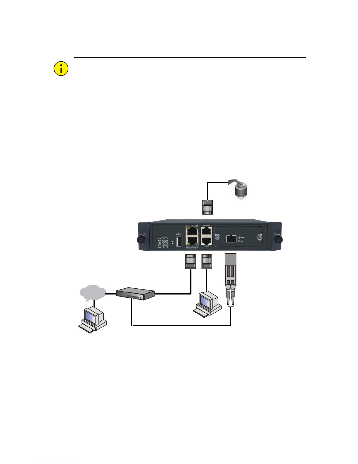
Front panel cable connection
Figure 2-2 Cable Connection on the Front Panel
Network
Serial port device
RJ45
SFP
PTZ camera
Page 16
8
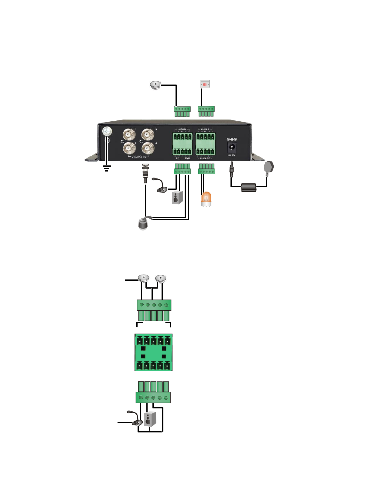
Back panel cable connection
Figure 2-3 Cable Connection on the Back Panel
Audio and alarm connection
Figure 2-4 Audio Connection
Sound pickup
Alarm input device
MIC
Speaker
box
Power
PTZ camera
Grounding
Alarm output device
AUDIO IN
INOUT
G A B
LINE
RS485
Audio input device
(MIC)
Audio output device
(speaker box)
1 2 G34
Audio input device
(sound pickup)
Page 17
9
Table 2-1 Terminal Connectors
Terminal Connector
Description
AUDIO IN (1, 2, 3, 4)
Audio input (mono)
LINE (IN, OUT)
Audio input and output for two-way audio
RS485 (A, B)
Connect to the RS485+ and RS485terminals on a peripheral
G
Grounding
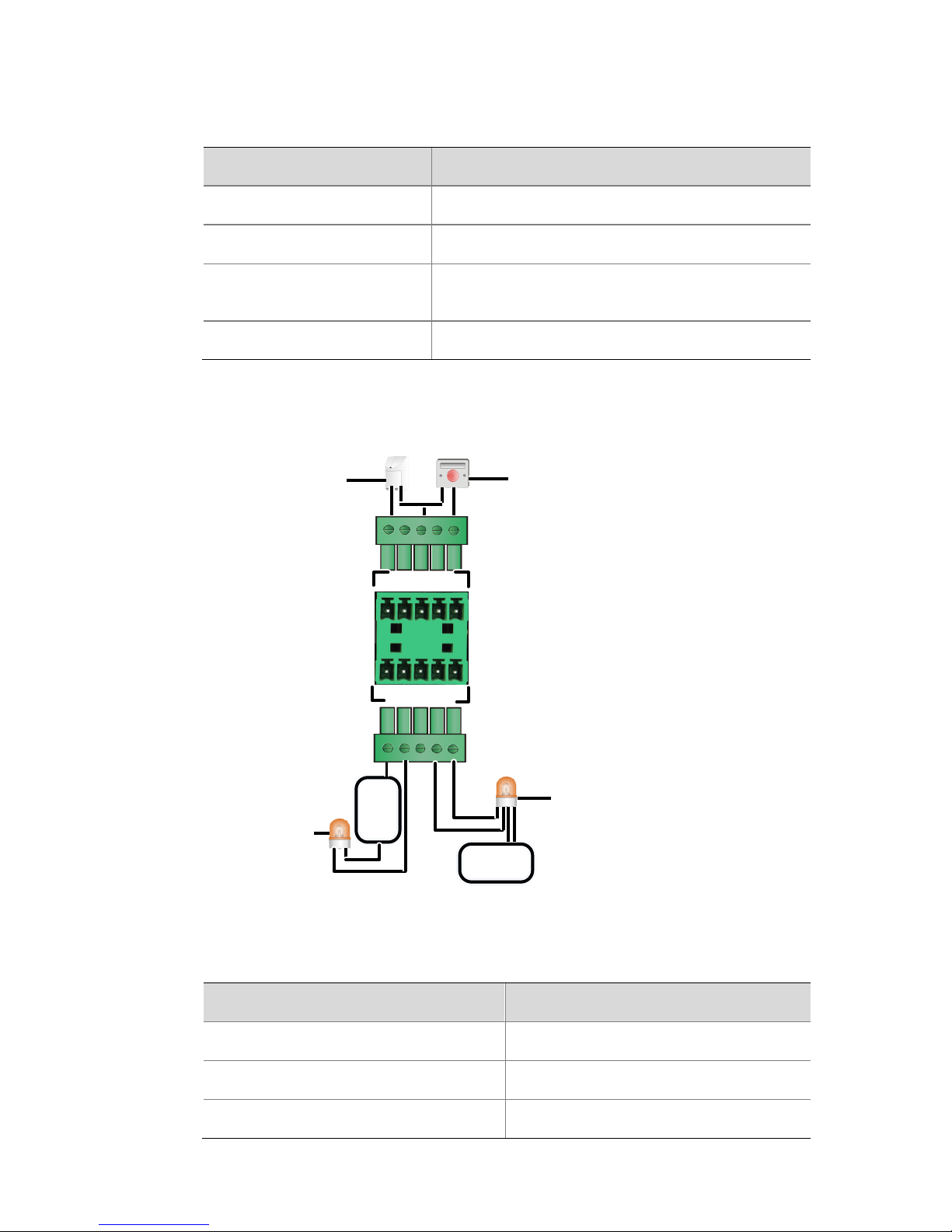
Figure 2-5 Alarm Connection
Table 2-2 Terminal Connectors
Terminal Connector
Description
ALARM IN (1, 2, 3, 4)
Allows four alarm inputs
ALARM OUT (1+, 1-), (2+, 2-)
Allows two alarm outputs
G
Grounding
ALARM IN
1 2 G 3 4
ALARM OUT
1+ 1-
G 2+ 2-
Power
+
-
Power+-
+
-
Alarm output device
Alarm input device
+
-
Alarm input device
Alarm output device
Page 18
10
NOTE!
The operating voltage and current for alarm output devices should not
exceed 12 VDC and 0.7 A.
Mounting a 16-channel DVS
Mount in a Protective Box
NOTE!
Use a 19-inch cabinet firm enough to hold the device. This section takes
a standard 19-inch cabinet as an example.
The device can be mounted without the use of any tray or slide rails. The
mounting ears alone can bear the total weight.
Preparation
Check that the cabinet is stabilized and grounded properly.
Check that no object is left inside the cabinet or placed nearby to
hinder the mount.
Determine an appropriate mounting position inside the cabinet.
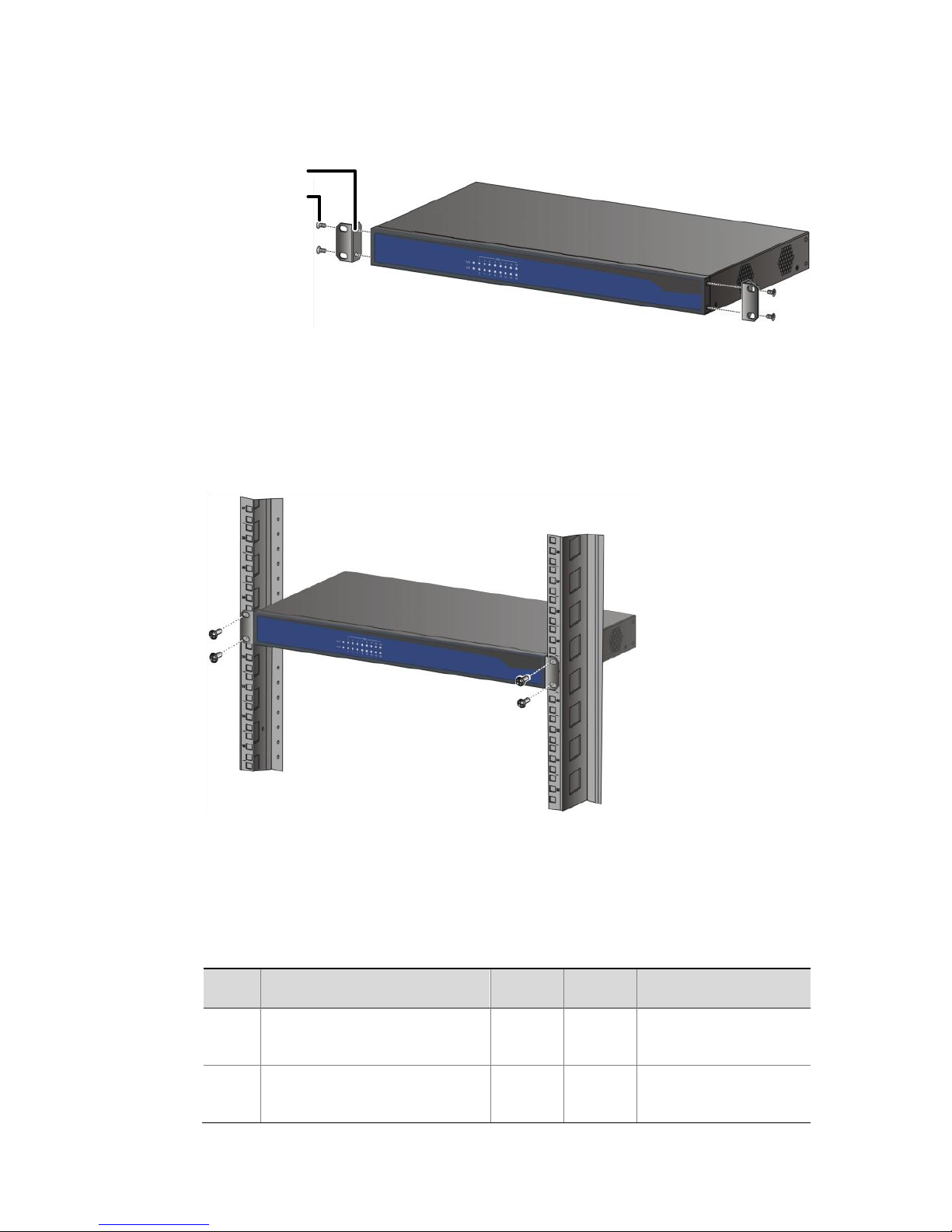
Install mounting ears
In the following figure the mounting ears are attached at the same side
as the front panel. They can also be attached at the same side as the
back panel.
1. Attach a mounting ear to the device and secure it with two M4*8
screws.
2. Install the other one in the same way.
Page 19
11
Figure 2-6 Installing Mounting Ears
Mount the device in the cabinet
Attach the device to the cabinet rails and then secure the mounting ears
to the cabinet rails using screws, as shown in the figure below.
Figure 2-7 Mounting in a 19-inch Cabinet
Verify the mount
Check against the following table to ensure the mount meets
requirements.
Table 2-3 Cabinet Mount Checklist
No.
Item
Yes
No
Remarks
1
Mounting ears are
secured to device
2
Mount position is
appropriate
Screw x 4 pcs
Mounting ear
Page 20
12
No.
Item
Yes
No
Remarks
3
Mounting ears are
secured to cabinet rails
Mount on a Workbench
Check the following when mounting the device on a workbench:
Check that the workbench is firm enough to hold the device.
Make sure the workbench is stabilized and grounded properly.
Use the protection pads supplied with the device. Remove the
stickers and then attach the pads to the bottom of the device.
CAUTION!
Allow at least 10cm of space surrounding the device for heat
dissipation.
Do not place anything heavy on the device.
Cable Connection
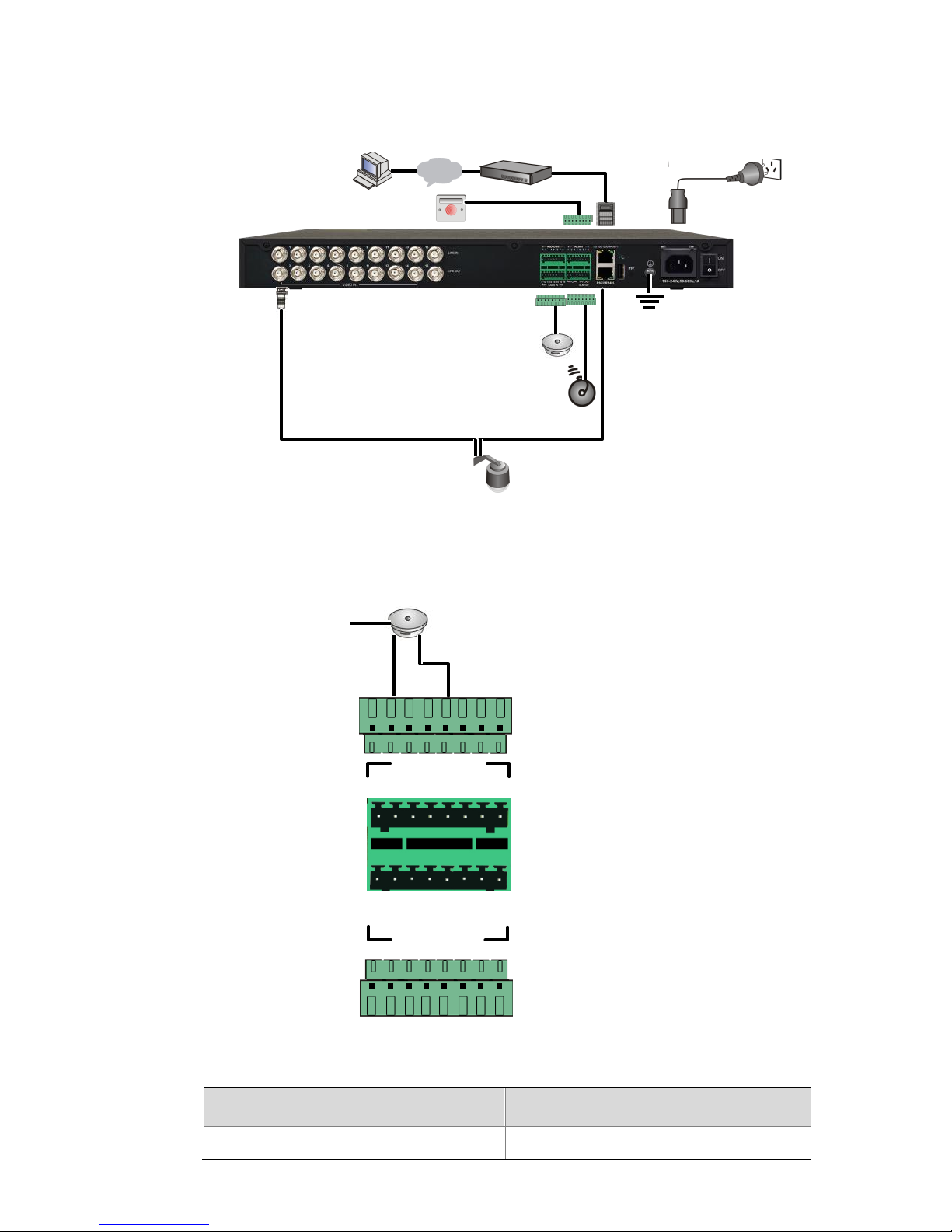
Connection on the back panel
See the illustration below and connect peripherals as needed. For more
connection instructions, refer to the corresponding documentation for
the peripherals.
Page 21
13
Figure 2-8 Connection on the Back Panel
Audio and alarm connections
Figure 2-9 Audio Connection
Table 2-4 Terminal Connectors
Terminal Connector
Description
AUDIO IN: 1–16
Allows 16 audio inputs
Sound
pickup
Alarm output
device
Grounding
PTZ camera
Power
Network
Alarm input
device
1 2 3 4 5 6 7 8
AUDIO IN
AUDIO IN
9 10 11 12 13 141516
Audio input device
(sound pickup)
Page 22

14
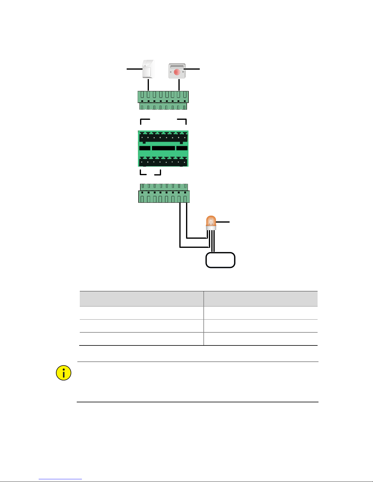
Connect alarm input and output device as needed. See Figure 2-10 for
details.
ALARM IN connectors 1 to 8 can be connected to a maximum of
eight alarm input devices. The following figure shows connection to
two alarm input devices only. Connections to more alarm input
devices are similar.
ALARM OUT(1+, 1-) and ALARM OUT(2+, 2-) terminal connectors
can be connected to two alarm output devices. The "+" and "-"
signs mean a pair of terminals, not polarity.
All the G terminal connectors provide the same function, so choose
one as convenient. One G terminal connector can be shared by
multiple alarm devices.
Page 23
15
Figure 2-10 Alarm Connection
Table 2-5 Terminal Connectors
Terminal Connector
Description
ALARM IN: 1, 2, 3, 4, 5, 6, 7, 8
Allows eight alarm inputs
ALARM OUT: (1+, 1-), (2+, 2-)
Allows two alarm outputs
G
Grounding
CAUTION!
The operating voltage and current for alarm output devices should not
exceed 12 VDC and 0.7 A.
Alarm input device
ALM IN
1 2 3 4 5 6 7 8
G
1+ 1- 2+
2-
ALM OUT
Power
+
-
Alarm input device
Alarm output device
Page 24
16
AC Power Cable Connection
WARNING!
Make sure the device is disconnected from power before connecting the
power cable.
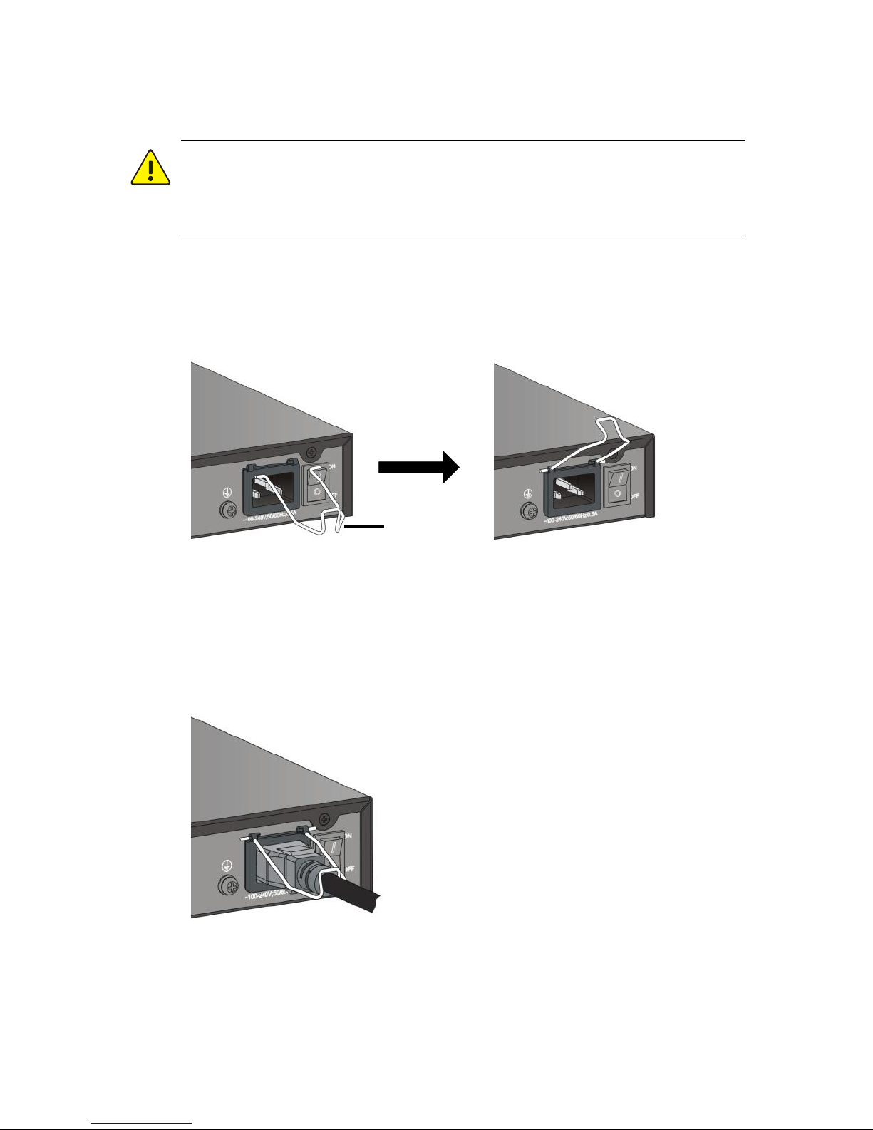
1. Attach the cable clip to the device as shown in the figure below.
Figure 2-11 Attach the Cable Clip
2. Connect the AC power cable, and then close the cable clip to
secure the power cable, as shown in the figure below.
Figure 2-12 Connect the AC Power Cable and Close the Cable Clip
Power cable clip
Page 25

17
Mount Verification
WARNING!
Verify the mount after you finish. Improper mount may cause personal
injury and device damage.
Before you start up the device, check that:
The device is stabilized with all screws fastened.
No object is placed on the device.
The power meets specifications.
All cables including the grounding wire are connected properly.
Starting the Device
Connect the device to power and start the device. Refer to Table 1-1 to
verify that the device is operating properly.
3 Login to the Web Interface
Log in to the Web interface to manage the device from a remote site.
Before login, check that:
The device is operating properly and connected to the client PC
through network.
Microsoft Internet Explorer (IE) is installed on the client PC. The
following IE versions are acceptable: 7.0, 8.0, 9.0, 10, and 11.
Proxy server is not enabled in the IE.
Page 26
18
NOTE!
By default, the IP address is 192.168.0.13, subnet mask is
255.255.255.0, and gateway is 192.168.0.1.
Use admin as the default username and password for your first
login. If you are using IE 11.0, make sure Document mode is not
set to Edge Mode under Tools > Developer Tools (F12) >
Emulation. Any other mode is acceptable.
Follow these steps to log in:
1. Launch the IE on your client PC and then enter the IP address of the
device in the address bar.
2. Enter the username and password and then click Login.
NOTE!
After login, click the menus and tabs to display the corresponding
configuration pages.
For detailed information about the initial configuration of your
device and parameter descriptions, please refer to the online help.
The default password is intended only for your first login and should
be changed immediately after login (Device > Password). A strong
password containing at least eight characters is recommended.
To log out of the Web interface, click Exit. A message appears. Click OK
to log out.
Page 27

BOM: 3101C0CE
 Loading...