

Page 1

Video Decoders
Quick Guide
Manual Version: V1.00
Page 2

Thank you for purchasing our product. If there are any questions, or
requests, please do not hesitate to contact the dealer.
Copyright
Copyright 2014-2015 Zhejiang Uniview Technologies Co., Ltd. All rights
reserved. No part of this manual may be copied, reproduced, translated,
or distributed in any form or by any means without prior consent in
writing from our company.
Trademark Acknowledgement
and other Uniview’s trademarks and logos are the property of
Zhejiang Uniview Technologies Co., Ltd. Other trademarks, company
names and product names contained in this manual are the property of
their respective owners.
Disclaimer
CAUTION!
The default password is used for your first login. To ensure account
security, please change the password after your first login. You are
recommended to set a strong password (no less than eight characters).
To the maximum extent permitted by applicable law, the product
described, with its hardware, software, firmware and documents, is
provided on an "as is" basis.
Best effort has been made to verify the integrity and correctness of
the contents in this manual, but no statement, information, or
recommendation in this manual shall constitute formal guarantee
of any kind, expressed or implied. We shall not be held responsible
for any technical or typographical errors in this manual. The
Page 3

contents of this manual are subject to change without prior notice.
Update will be added to the new version of this manual.
Use of this manual and the product and the subsequent result shall
be entirely on the user's own responsibility. In no event shall we be
reliable to you for any special, consequential, incidental, or indirect
damages, including, among others, damages for loss of business
profits, business interruption, or loss of data or documentation, or
product malfunction or information leakage caused by cyber attack,
hacking or virus in connection with the use of this product.
Video and audio surveillance can be regulated by laws that vary
from country to country. Check the law in your local region before
using this product for surveillance purposes. We shall not be held
responsible for any consequences resulting from illegal operations
of the device.
The illustrations in this manual are for reference only and may vary
depending on the version or model. The screenshots in this manual
may have been customized to meet specific requirements and user
preferences. As a result, some of the examples and functions
featured may differ from those displayed on your monitor.
This manual is a guide for multiple product models and so it is not
intended for any specific product.
Due to uncertainties such as physical environment, discrepancy
may exist between the actual values and reference values provided
in this manual. The ultimate right to interpretation resides in our
company.
Environmental Protection
This product has been designed to comply with the requirements on
environmental protection. For the proper storage, use and disposal of
this product, national laws and regulations must be observed.
Page 4

Safety and Compliance Information
Safety Symbols
The symbols in the following table may be found on installation-related
equipment. Be aware of the situations indicated and take necessary
safety precautions during equipment installation and maintenance.
Symbol
Description
Generic alarm symbol: To suggest a general safety
concern.
ESD protection symbol: To suggest
electrostatic-sensitive equipment.
Electric shock symbol: To suggest a danger of high
voltage.
The symbols in the following table may be found in this manual.
Carefully follow the instructions indicated by the symbols to avoid
hazardous situations and use the product properly.
Symbol
Description
WARNING!
Indicates a hazardous situation which, if not
avoided, could result in bodily injury or death.
CAUTION!
Indicates a situation which, if not avoided, could
result in damage, data loss or malfunction to
product.
NOTE!
Indicates useful or supplemental information
about the use of product.
Safety Information
Installation and removal of the unit and its accessories must be carried
out by qualified personnel. Please read all of the safety instructions
below before installation and operation.
Page 5

This device is a class A product and may cause radio interference.
Take measures if necessary.
While shipping, the device should be packed in its original packing.
Verify that installation is correct. Incorrect cable connection may
cause personal injury or device damage.
The installation must be made by qualified personnel and should
conform to all the local codes.
If the product does not work properly, please contact your dealer.
Never attempt to disassemble the device yourself. We shall not
assume any responsibility for problems caused by unauthorized
repair or maintenance.
Ensure a proper operating environment, including temperature,
humidity, ventilation and power supply. Make sure the device is
properly grounded and the lightning protection meets
requirements. Keep the device from moisture, dust, strong
electromagnetic radiation and vibration.
Power down the device before connecting and disconnecting
accessories and peripherals.
Protect the power cable from being stepped on or pressed,
particularly at the plug, receptacle, and the part leading out of the
device.
Strictly follow the procedure to shut down the device. Sudden
power failures can cause disk damage and functional abnormalities.
In an environment where power supply is frequently interrupted,
use an Uninterrupted Power Supply (UPS).
Improper use or replacement of the battery may result in hazard of
explosion. Use the manufacturer recommended battery.
Take necessary measures to ensure data security and protect the
device from network attack and hacking (when connected to
Internet). Possible risks and consequences are at user's sole
discretion.
Page 6

WARNING!
Never look at the transmit laser while the power is on. Never look
directly at the fiber ports and the fiber cable ends when they are
powered on.
Use of controls or adjustments to the performance or procedures
other than those specified herein may result in hazardous laser
emissions.
Regulatory Compliance
FCC Part 15
This equipment has been tested and found to comply with the limits for
digital device, pursuant to part 15 of the FCC Rules. These limits are
designed to provide reasonable protection against harmful interference
when the equipment is operated in a commercial environment. This
equipment generates, uses, and can radiate radio frequency energy and,
if not installed and used in accordance with the instruction manual, may
cause harmful interference to radio communications. Operation of this
equipment in a residential area is likely to cause harmful interference in
which case the user will be required to correct the interference at his
own expense.
This product complies with Part 15 of the FCC Rules. Operation is subject
to the following two conditions:
1. This device may not cause harmful interference.
2. This device must accept any interference received, including
interference that may cause undesired operation.
Page 7

LVD/EMC Directive
This product complies with the European Low Voltage Directive
2006/95/EC and EMC Directive 2004/108/EC.
WEEE Directive–2002/96/EC
The product this manual refers to is covered by the Waste Electrical &
Electronic Equipment (WEEE) Directive and must be disposed of in a
responsible manner.
Page 8

i
Contents
1 Overview .............................................................................................. 1
Appearance ................................................................................................... 1
LEDs ............................................................................................................... 2
Main Ports ..................................................................................................... 3
2 Installing the Device ............................................................................. 5
Preparation ................................................................................................... 5
Checking the Device Package ............................................................... 5
Checking the Installation Environment................................................. 5
Cable Requirements ............................................................................. 6
Installation Flow Chart .................................................................................. 8
Installing the Device in a Rack ..................................................................... 10
Preparing for the Installation.............................................................. 10
Installing the Mounting Brackets ........................................................ 10
Installing the Device in the Rack ......................................................... 11
Verifying the Installation .................................................................... 12
Installing the Device on a Workbench ........................................................ 13
Preparation for the Installation .......................................................... 13
Installation Procedure ........................................................................ 13
Connecting Cables ....................................................................................... 13
Cabling Requirements ........................................................................ 13
Example for Connecting Cables .......................................................... 14
Connecting the Ground Wire .............................................................. 15
Connecting the Audio Cables and Alarm Cables ................................. 17
Connecting video cables ..................................................................... 19
Connecting Network Cables ............................................................... 19
Connecting the AC Power Cord .......................................................... 19
Page 9

ii
Connecting RS-232 Serial Cables ........................................................ 21
Connecting a Third-Party Device ........................................................ 21
Verifying the Installation ............................................................................. 21
Starting Up the Device ................................................................................ 21
3 Logging In to and Out of the Device ..................................................... 22
4 Technical Specifications ...................................................................... 22
Page 10

1
1 Overview
NOTE!
This manual describes the device hardware information and installation
procedure, and guides you through logging into the Web interface.
This series video decoders (referred to as device in this manual) are new
generation HD network video decoder terminals. The device is designed
for remote video surveillance and can be widely applied in various
real-time surveillance applications for monitoring audios and videos
remotely in real time.
For information about the technical specifications of the device, see
Technical Specifications.
Appearance
Figure 1-1 Front view
1: RUN LED
2: NET1
LED
3: DEC
LED
4: Alarm
LED
5: NET2 LED
1
2
3
4
5
Page 11
2
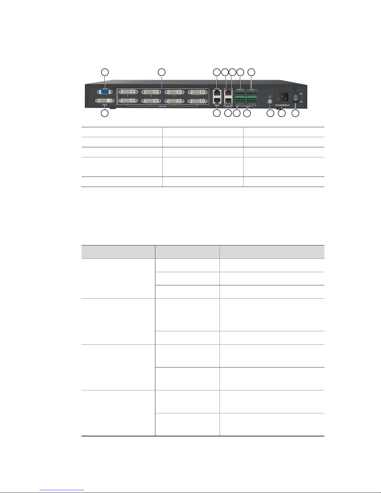
Figure 1-2 Rear view
1: VGA IN port
2: DVI-I OUT port
3: RS-485 port (RJ-45)
4: ACT LED
5: LINK LED
6: AUDIO OUT port
7: ALM IN port
8: DVI IN port
9: RS-232 port (RJ-45)
10: Two Ethernet
copper ports
11: LINE port
12: ALM OUT port
13: Grounding screw
14: AC power input
15: Power switch
LEDs
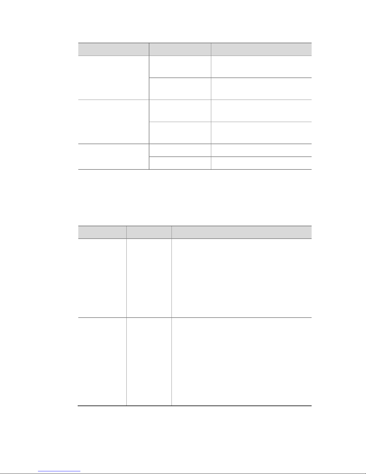
Table 1-1 LED description
LED
Status
Description
Running LED
Flashing green
The device is starting up.
On (Green)
The device is operating.
Off
The device is shut down.
Alarm LED
On (Red)
At least one alarm, for
example, temperature alarm,
is present.
Off
No alarm is present.
LINK LED for
Ethernet copper
port 1 (NET1)
On (Green)
A link to the Ethernet copper
port 1 is present.
Off
No link to the Ethernet
copper port 1 is present.
LINK LED for
Ethernet copper
port 2 (NET2)
On (Green)
A link to the Ethernet copper
port 2 is present.
Off
No link to the Ethernet
copper port 2 is present.
2 7
8
11
1 5 6
9
3 4
13
10
12
14
15
Page 12
3
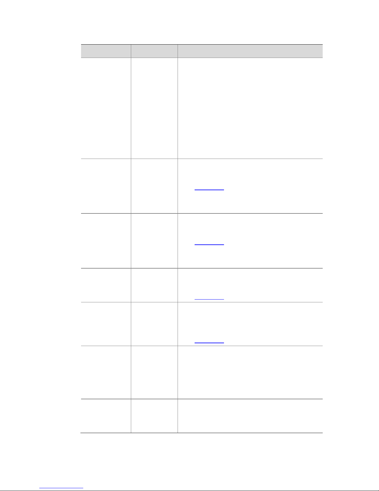
LED
Status
Description
Decoding LED (DEC)
Flashing green
The device is displaying
video.
Off
The device stops displaying
video.
Active LED (ACT)
Flashing yellow
Data is being transmitted or
received.
Off
No data is being transmitted
or received.
Link LED
On (Green)
A link is present.
Off
No link is present.
Main Ports
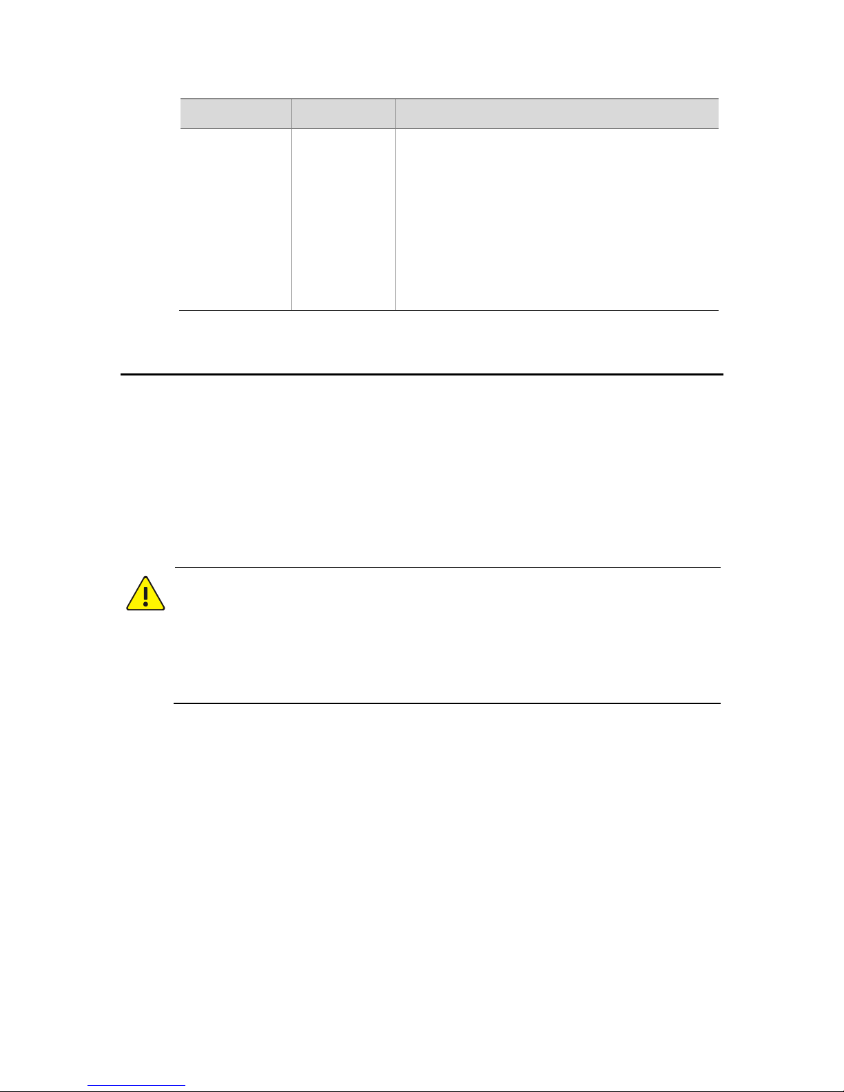
Table 1-2 Port description
Port
Quantity
Description
VGA IN
1
VGA video input port, used for receiving
analog video signals from the VGA output
port of a video source.
Note: Make sure the connected video
source supports the following resolutions:
1024*768/60HZ, 1280*720/60HZ,
1280*1024/60HZ, 1920*1080/60HZ,
1920*1080/50HZ.
DVI IN
1
DVI-D video input port, used for receiving
digital video signals from DVI-D output
port and HDMI output port of the video
source.
Note: Make sure the connected video
source supports the following resolutions:
1024*768/60HZ, 1280*720/60HZ,
1280*1024/60HZ, 1920*1080/60HZ,
1920*1080/50HZ.
Page 13
4
Port
Quantity
Description
DVI-I OUT
4 or 8,
depending
on model
DVI-I video output port, used for
outputting video signals to a display
output device with HDMI port, DVI-D port,
VGA port (5-wire), or YPbPr port.
Note: Make sure the connected display
output device supports the following
resolutions: 1024*768/60HZ,
1280*720/60HZ, 1280*1024/60HZ,
1360*768/60HZ, 1600*1200/60HZ,
1920*1080/60HZ, 1920*1080/50HZ.
AUDIO OUT
4 or 8,
depending
on model
Used to output audio signals.
Phoenix connector. For more information,
see Table 2-3.
Electrical level: 2.0V to 2.4V (P-P);
Impedance: 5 Kohm
LINE
1 input
1 output
Used to input and output audio signals.
Phoenix connector. For more information,
see Table 2-3.
LINE I: 2V (P-P), 10 Kohm; LINE O: 2V (P-P),
600 ohm
ALM IN
8
Used to input Boolean alarm signals.
Phoenix connector. For more information,
see Table 2-3.
ALM OUT
6
Used to output alarm signals through
relay.
Phoenix connector. For more information,
see Table 2-3.
RS485
1
Serial port, used to interoperate with the
connected device, for example, to
transmit transparent channel data.
RJ-45 connector, four wires, supporting
full duplex and half duplex.
RS232
1
Serial port, used to debug and maintain
the device.
RJ-45 connector.
Page 14
5
Port
Quantity
Description
Ethernet
copper port
2
Used to connect to Ethernet to
communicate with the devices on the
network, to receive IP camera streams,
and to be configured by the client through
Web interface.
10M/100M/1000M/auto-sensing, half
duplex/full duplex/auto-sensing, RJ-45
connector.
2 Installing the Device
Preparation
Checking the Device Package
Before you install the device, verify the device model and check the
components and their quantity against the packing list to make sure all
items listed are included in the package.
WARNING!
Do not remove the dismantlement-preventive seal from the device
chassis cover without permission. To open the chassis, contact your
dealer. Otherwise, we shall not be held liable for any consequence
caused thereby.
Checking the Installation Environment
The device can be installed indoors only, and must meet the following
requirements:
Use correct lightning protection devices for the device power
source, audio/video signals, and RS-485 ports.
Page 15

6
Ground the device correctly through the grounding screw. For
more information, see the Encoder and Decoder Cable Connection
Guide.
Cable Requirements
NOTE!
For information about how to select the common cables, contact your
dealer.
VGA cables
Use UL-certified VGA cables with shielding rings and gold-plated
connectors.
Use cables with pure copper or oxygen-free copper shielded with
tinplated layer. The wire gage of the core conductor should be in
the range of 24 AWG to 28 AWG. A smaller gage means a thicker
wire diameter and a better transmission effect.
The transmission distance of an ordinary cable is 15 meters (49.21
ft), and that of a better project-level cable can be 50 meters
(164.04 ft).
HDMI cables
Use HDMI Association-certified HDMI cables with shielding rings
and gold-plated connectors.
Use cables with pure copper with 96 copper braiding or more. The
wire gage of the core conductor should be in the range of 24 AWG
to 28 AWG.
If you use an HDMI cable longer than 10 meters (32.81 ft) to
transmit 1080P signals, you are recommended to use 24 AWG. If
you want to transmit signals for 20 meters (65.62 ft) or longer, you
Page 16

7
are recommended to use an HDMI signal amplifier or HDMI
extension cord.
DVI cables
A DVI connector can transmit multiple types of video signals, and
different cables are used for different signals. If the DVI connector is not
connected to an adapter, the requirements for DVI cables are similar
with those for HDMI cables.
Audio cables
Use 4-wire shielded cables (RVVP) or unshielded digital communication
cables (UTP). The sectional area of the cable conductor should be large,
for example, 0.5 mm2. You are recommended to use dedicated shielded
audio cables, and the cable length is 100 meters (328.08 ft). Commonly
used audio cables include RCA audio cables and ordinary coaxial cables.
Alarm cables
Twisted pair cables are recommended. The wire gage of the insulated
core conductor should be in the range of 22 AWG to 28 AWG (24 and 26
AWG are recommended). The maximum DC impedance must not be
more than 100 ohm.
The following table shows the maximum length of alarm cables for wire
gages, taking 100 ohm as the benchmark.
Table 2-1 Maximum alarm cable length for different wire gages
Wire gage (AWG)
Maximum cable length
22
1453 m (4767.06 ft)
24
914 m (2998.69 ft)
26
570 m (1870.08 ft)
28
360 (1181.10 ft)
Page 17

8
Network cables
Use twisted-pair cables. Currently, twisted pair cables include
unshielded twisted pair (UTP) and shielded twisted pair (STP). STP cables
are shielded with aluminum foil for radiation reduction purpose. STP
cables are more expensive than UTP cables, and they are harder to
install.
Ground wire
The length of the ground wire should be no more than 30 meters (98.43
ft), and its impedance must be less than 5 ohm. For more information,
see Standard YD5098.
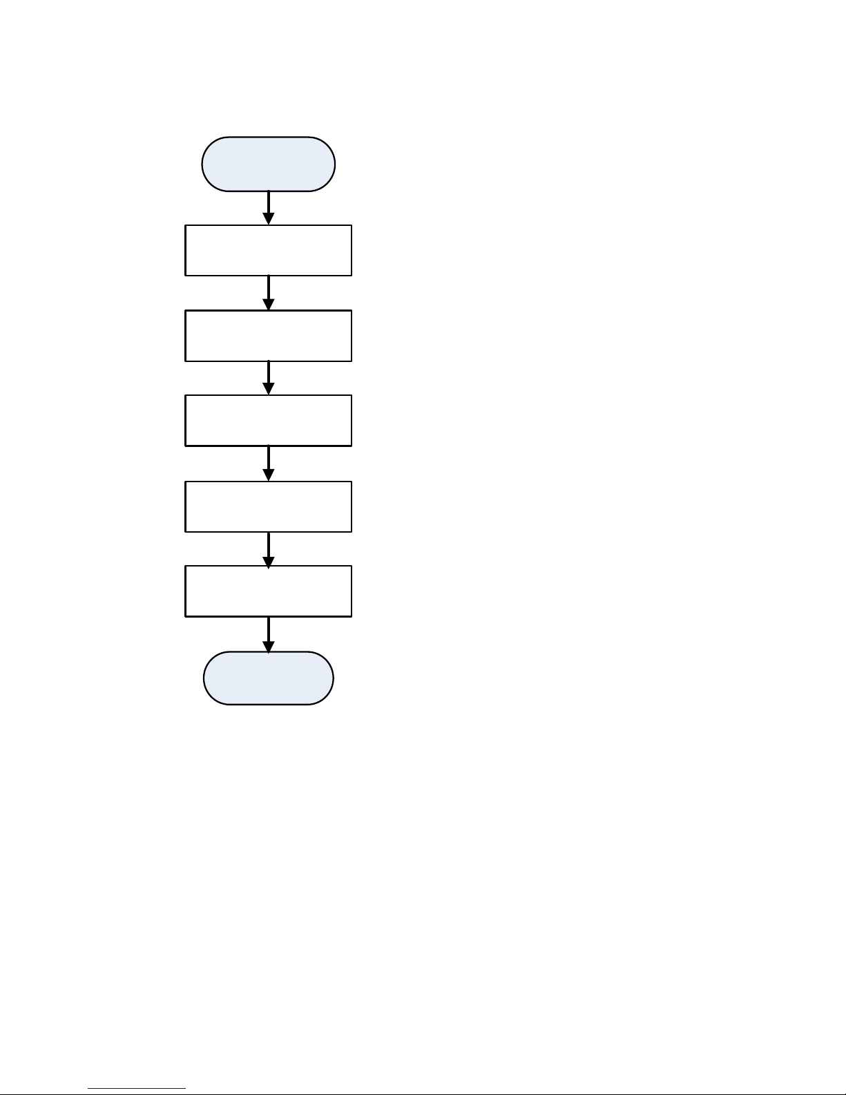
Installation Flow Chart
Make sure the device is disconnected from the power source when you
install the device.
Page 18
9
Figure 2-1 Installation flow chart
Check before installation
Ensure installation position
meets requirements
Install device in indoor rack
or indoor workbench
Connect cables
Verify that installation is ok
Finish
Begin
Page 19

10
Installing the Device in a Rack
NOTE!
You can install your device in a standard 19-inch rack. The rack
should meet the requirement on bearing the weight of the device
and its accessories. The following section uses a standard 19-inch
rack as an example.
Before the installation, make sure the rack is stable and correctly
grounded, and make sure there are no obstacles that might hamper
the installation inside or near the rack.
You can front-mount or rear-mount your device in a standard 19-inch
rack with mounting brackets.
Installing the device to a rack does not require sliding rails or a tray. The
mounting brackets can bear the weight of the device.
The following describes how to front-mount the device. The
rear-mounting method is similar, and thus not provided in this manual.
Preparing for the Installation
Examine the grounding and stability of the rack, determine the
device installation position in the rack, and make sure there are no
obstacles that might hamper the installation inside or near the
rack.
Move your device to a place near the rack.
Installing the Mounting Brackets
Checking before the installation
Mounting brackets are placed in the accessory package with screws.
Each device is shipped with two identical mounting brackets.
Page 20
11
Installation procedure
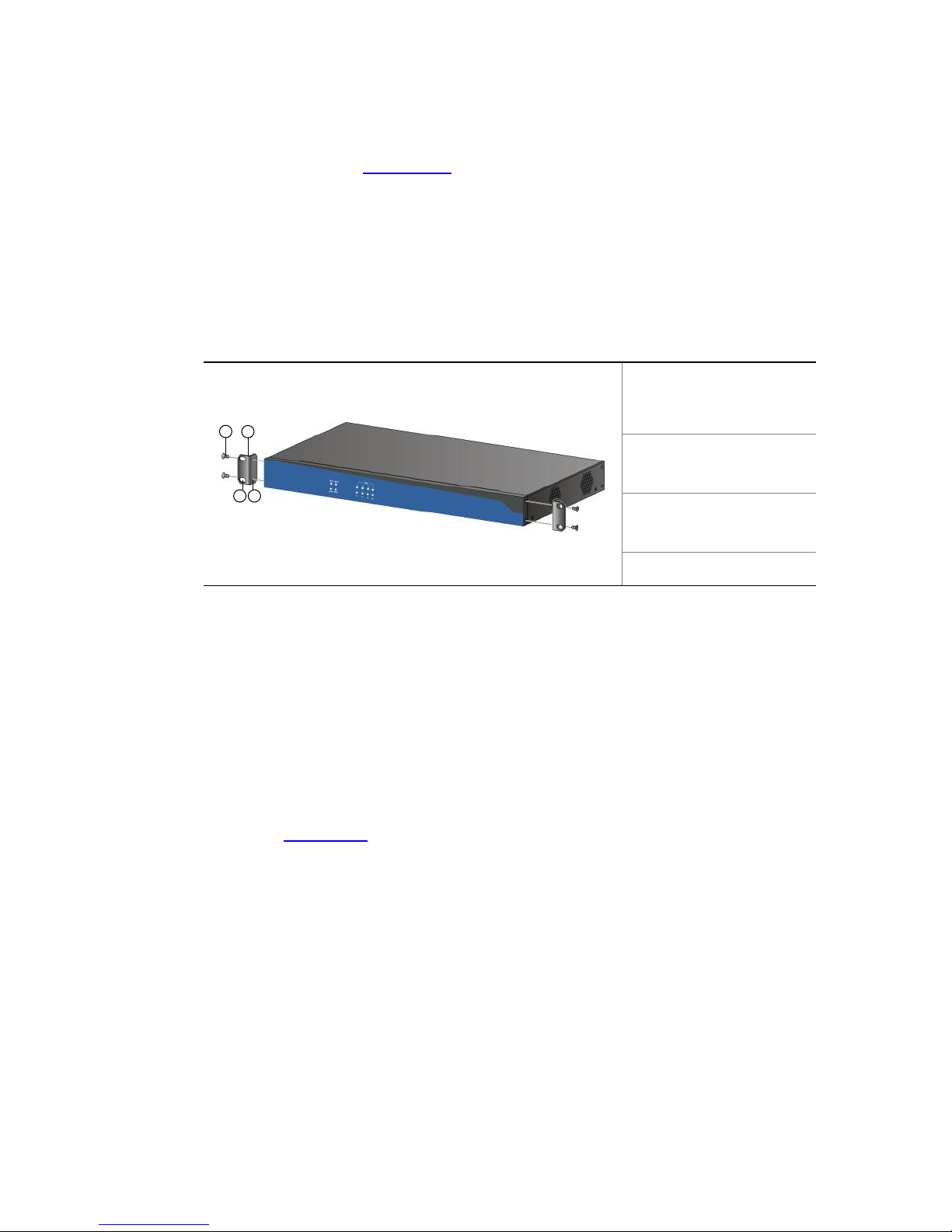
1. As shown in Figure 2-2, put the screw-hole side of the bracket
against the chassis tightly, align the screw holes on the bracket
with those on the chassis, and then fix the bracket to the chassis
tightly with two M4*8 screws.
2. Use the same method to install the other mounting bracket.
Figure 2-2 Installing the mounting brackets
1: Screws (four)
2: Mounting bracket
3: Waist-shaped hole
4: Screw hole
Installing the Device in the Rack
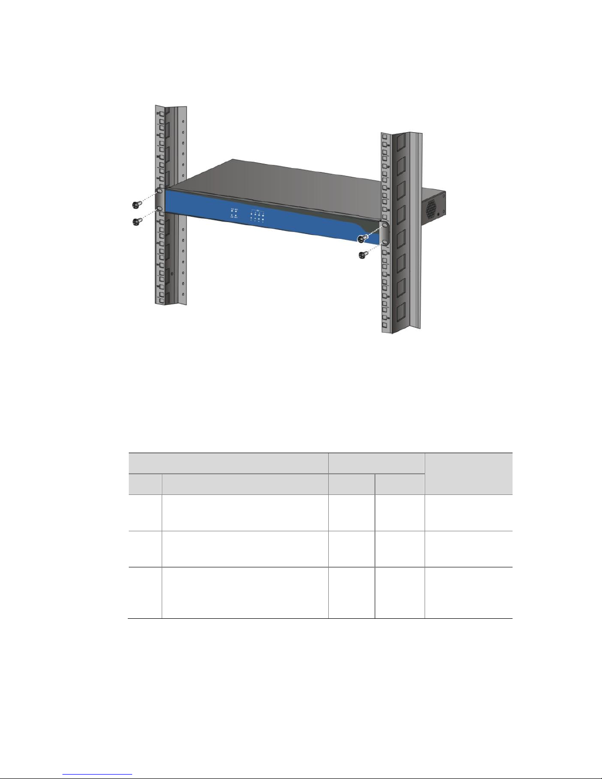
Place your device horizontally to a proper position in the rack, and align
the mounting brackets along the front posts of the rack. Put the screws
through the waist-shaped holes to contact the floating nuts on the front
posts, and fix the mounting brackets to the front posts of the rack, as
shown in Figure 2-3.
1
2
43
Page 21
12
Figure 2-3 Installing the device in the rack
Verifying the Installation
After you install the device in the rack, examine the installation against
the following checklist. Make sure all check results are positive.
Table 2-2 Installation checklist
Item
Result
Remarks
No.
Description
Yes
No
1
The mounting brackets are
fixed tightly to the device.
2
The device is installed at a
correct position.
3
The mounting brackets are
fixed tightly to the posts on
the rack.
Page 22

13
Installing the Device on a Workbench
If you do not have a standard 19-inch rack, you can install your device on
a workbench.
Preparation for the Installation
Make sure the workbench is sturdy enough to bear the weight of
your device, its accessories, and cables.
Make sure the workbench is stable and correctly grounded.
Your device is shipped with foot mats. Remove the stickers from
the feet mats, and stick the foot mats to the correct positions on
the bottom of your device.
Installation Procedure
1. Lift the device and move it near to the workbench.
2. Lift the device and place it on the workbench.
CAUTION!
To ensure proper heat dissipation, keep at least a clearance of 10 cm
(3.94 in.) around the device.
Do not place any heavy objects on the device.
Connecting Cables
Cabling Requirements
Separate service cables, such as network cables and audio/video cables,
from power cords. You can bundle long cables with cable ties and stick
labels on them for easy identification.
If your device is installed in a standard 19-inch rack, you can arrange the
power cords either over or under the rack to separate from signal cables.
Page 23

14
Generally, signal cables are wired through the cabling rack on the top of
the rack or through the cabling trough under the ground.
CAUTION!
To avoid bodily injury and device damage, make sure the device is
powered off before you connect the cables.
For related standards for the external cables of the device, see Cable
Requirements.
Do not bundle cables near the air outlet of the device to avoid
speedy aging. Fasten the cables near the device and keep the cables
loose between the ports and the fastening points.
Example for Connecting Cables
NOTE!
The following is an example. The cable connection for different devices is
similar. The actual ports and corresponding devices are subject to the
user site.
Connect an external device to your device as required. For more
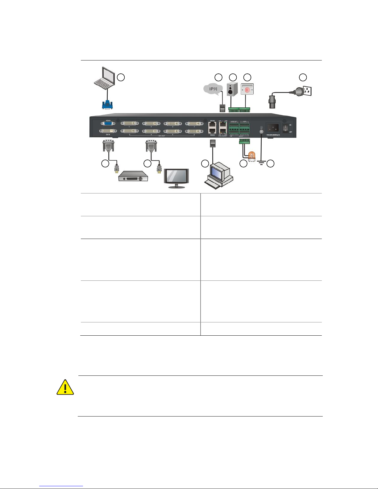
information, see related documents for the external device.
Page 24
15
Figure 2-4 Cable connection diagram
1: VGA port video source, such as
PC.
2: Connect your device to the
network through a network cable.
3: Audio output device, such as
speaker
4: Alarm input device.
5: Power source.
6: Connect your device to a video
source (such as DVD) through the
DVI-D-to-HDMI cable, taking HDMI
port as an example.
7: Connect your device to a display
output device through the
DVI-I-to-HDMI cable, taking HDMI
port as an example.
8: Connect your device to a serial
port device (such as a PC) through
the serial port cable.
9: Alarm output device.
10: Grounding
Connecting the Ground Wire
WARNING!
To ensure human and device safety against lightning and interference,
the device must be grounded correctly.
1 2 3 4 5
6 7
8
9
10
Page 25
16
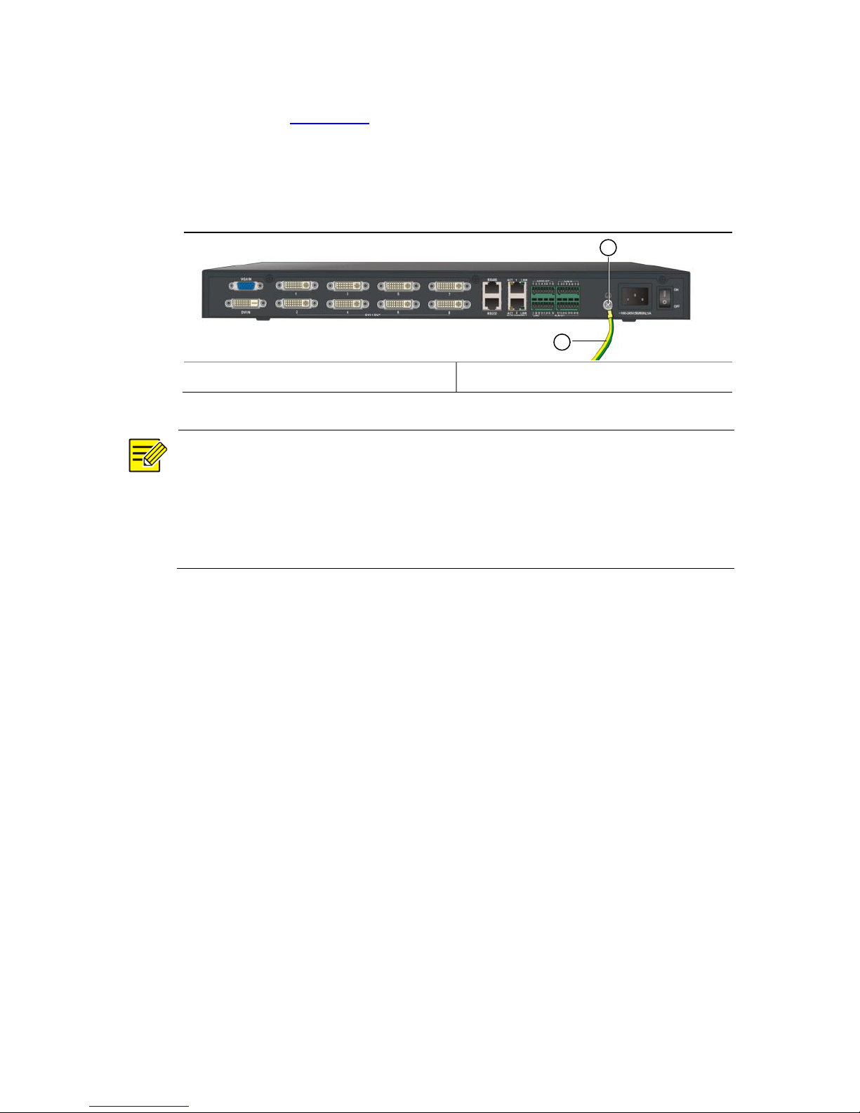
As shown in Figure 2-5, connect one end of the ground wire to the
grounding screw on the device, and connect the other end to a reliable
grounding point.
Figure 2-5 Connecting the ground wire
1: Grounding screw
2: Ground wire
NOTE!
Generally, a rack has a grounding bar, where you can connect the ground
wire. In actual installation, you can connect the ground wire correctly
according to the site conditions. For more information, see the Encoder
and Decoder Cable Connection Guide.
1
2
Page 26
17
Connecting the Audio Cables and Alarm Cables
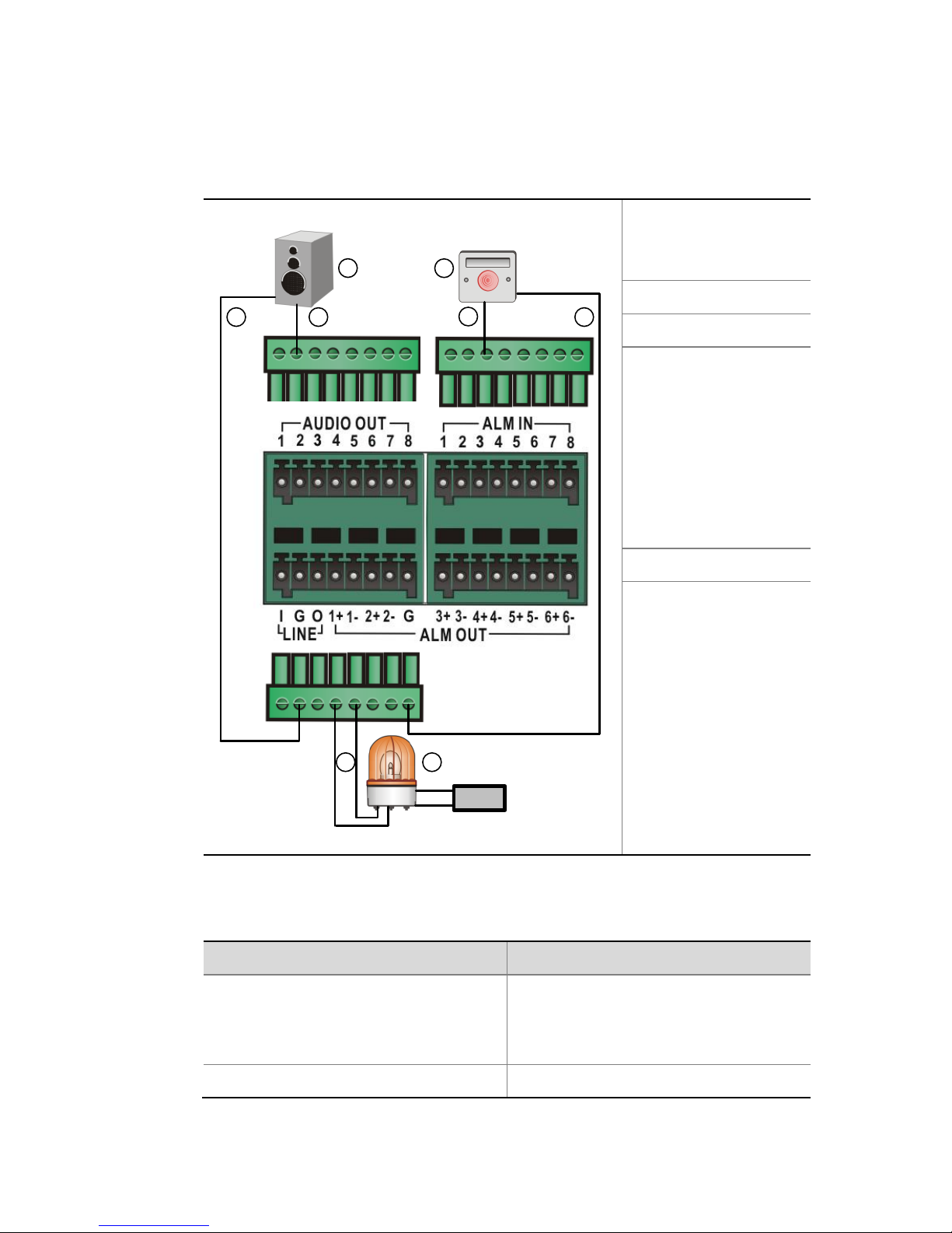
Figure 2-6 Connecting the audio cables and alarm cables
1: Audio output
device, such as
speaker
2: Ground wire
3: Audio cable
4:
Normally-open/nor
mally-closed
Boolean alarm input
device, such as
audio control or
temperature control
alarm device
5: Alarm cable
6:
Normally-open/Nor
mally-closed
Boolean alarm
output device, for
example, alarm
lamp. You can
connect the alarm
lamp in many ways.
Here is only one
example.
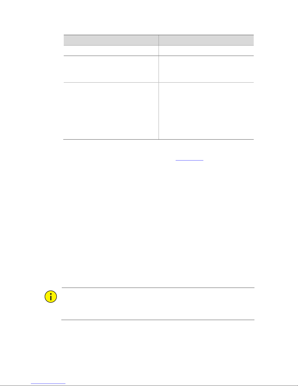
Table 2-3 Phoenix connector
Pin
Description
AUDIO OUT:
1, 2, 3, 4
1, 2, 3, 4, 5, 6, 7, 8
Audio signal output.
LINE: I, O
Audio input and output.
1
2
Power
-
+
3
4
5
65
2
Page 27
18
Pin
Description
ALM IN: 1, 2, 3, 4, 5, 6, 7, 8
Alarm signal inputs 1 to 8.
ALM OUT:
(1+,1-), (2+,2-), (3+,3-), (4+,4-),
(5+,5-), (6+,6-)
Alarm signal outputs 1 to 6.
LINE: G
ALM OUT: G
Ground
Note: All G pins of the phoenix
connector are the same for
grounding purpose. You can select
any proper G pin for cable
connection. Multiple external
devices can share a G pin.
Alarm cable connection is illustrated in Figure 2-6. This figure is for
reference only.
The alarm input pins 1 to 8 of the phoenix connector can connect
to eight alarm input devices. The figure shows only one connection
and the connection method for the other alarm input devices is
similar. In actual installation, make sure the connections
correspond to the alarm input port configurations on the Web
interface.
The alarm output pin pairs (1+, 1-) to (6+, 6-) of the phoenix
connector can connect to six alarm output devices. The plus sign
and minus sign mean a pin pair rather than polarity identification.
In actual installation, make sure the connections correspond to the
Boolean output channel configurations on the Web interface.
CAUTION!
The operating voltage and current of the power source for the Boolean
alarm output device should be no more than 12V DC and 0.7A.
Page 28
19
Connecting video cables
As shown in Figure 2-4, connect one end of a video cable to the video
input or output port of the device, and connect the other end to the
video device.
For the DVI-D input port and DVI-I output port, you can use a
DVI-to-HDMI cable or a DVI-to-VGA cable, or use adapter connector to
connect to a proper video device. For more information about adaption
ports, see Table 1-2.
NOTE!
Do not over-bend, twist, or heavily press HDMI cables.
Connecting Network Cables
As shown in Figure 2-4, connect one end of the network cable to the
Ethernet copper port of the device, and connect the other end to the IP
network.
Connecting the AC Power Cord
WARNING!
Before you connect the power cord, make sure the power switch of your
device is turned off to avoid possible bodily injury and device damage.
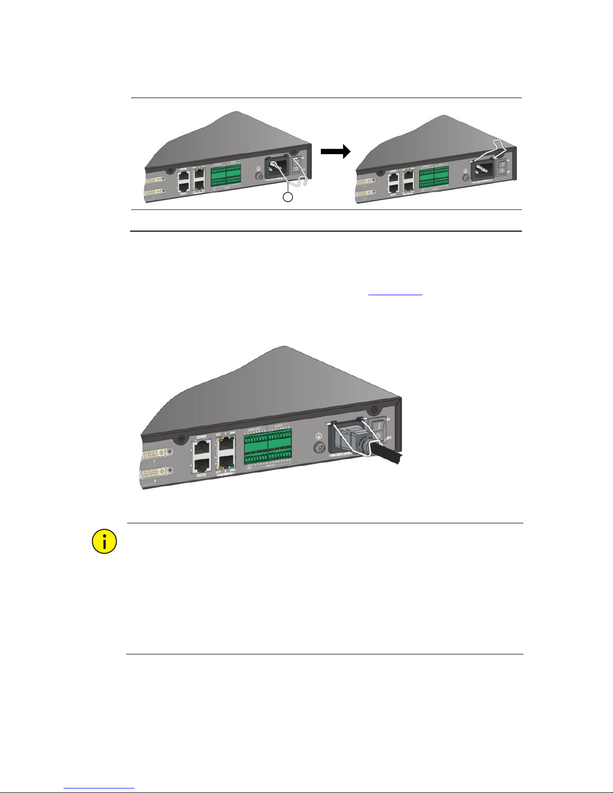
1. Take out the cable-retention clip from the package, and install it to
your device, as shown in Figure 2-7.
Page 29
20
Figure 2-7 Installing the cable-retention clip
1: Cable-retention clip.
2. Connect the AC power cord and turn the cable-retention clip to
hold the power cord tight, as shown in Figure 2-8.
Figure 2-8 Connecting the AC power cord
CAUTION!
When you connect the other end of the power cord to the power source,
you are recommended to use a single-phase three-wire power socket
with neutral point or multi-function computer power socket. Make sure
the neutral point of the power socket is correctly grounded. Generally,
the neutral points of the power supply system of the building have been
grounded correctly during construction.
1
Page 30

21
Connecting RS-232 Serial Cables
As shown in Figure 2-4, when you use the RS-232 serial cable to connect
your device with a serial port device (for example, a PC) through the
RS-232 serial port, see the Encoder and Decoder Cable Connection
Guide.
Connecting a Third-Party Device
When you use the serial cable to connect your device with a third-party
device through the RS-485 serial port in transparent channel mode, see
the Encoder and Decoder Cable Connection Guide.
Verifying the Installation
WARNING!
To avoid bodily injury and device damage caused by incorrect cable
connection, verify the installation before you connect the device to the
power source.
To verify the installation, check the following:
The device is installed stably with all screws fixed tightly.
No objects are placed on the top of the device chassis.
The device is grounded, and all cables are connected correctly.
The power voltage is stable. The selected power source meets the
requirements as described in Technical Specifications.
Starting Up the Device
After the cables are connected, connect the device with the power
source, and start up the device. Examine the device status according to
Table 1-1.
Page 31

22
3 Logging In to and Out of the Device
You can manage and maintain the device through the Web interface.
Before you log into the device, verify that:
The device is operating correctly.
The network connection between the PC and the device is normal.
The PC is installed with Microsoft Internet Explorer 7.0 or higher.
The browser on the PC is not configured with the proxy server.
The default IP address of the device is 192.168.0.14, the subnet mask is
255.255.255.0, and the default gateway is 192.168.0.1.
For the first login, use admin as both the username and password.
To log into the Web interface:
1. Use the IE browser on your PC to visit the IP address of the device.
2. On the login page, enter your username and password to access
the Web interface.
You can select a menu item on the Web interface and select a tab to
enter the corresponding configuration page.
For information about the initial configuration and other parameter
configurations, see the online help by clicking the Help menu.
For the first login, you are recommended to change the default login
password by selecting Maintenance > Password.
To log out of the device, you can click the Exit menu and confirm your
operation to return to the login page.
4 Technical Specifications
For detailed specification of the device, see the product brochure.
Page 32
23
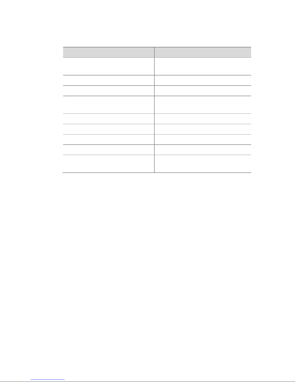
Table 4-1 Technical specifications
Item
Description
Dimensions (W × D x H)
43.6 mm × 440 mm × 320 mm
(17.32" × 9.45" in x 1.72")
Weight
4 kg (8.82 lb)
Operation voltage
100 V to 240 V
Max. power consumption
50W to 70W, depending on the
device model
Operation temperature
–10°C to +55°C (14°F to 131°F)
Operation humidity
10% to 95% (non-condensing)
Storage temperature
–40°C to +70°C (–40°F to +158°F)
Storage humidity
5% to 95% (non-condensing)
Altitude
–60 m to +5000 m (–196.85 ft to
+16404.20 ft)
This device is an A-category product, which might cause radio
interference. To eliminate such interference, you need to take proper
measures.
Page 33

BOM: 3101C0CJ
 Loading...