

Page 1

LineMicro
™
UNO
R
INSTRUCTION MANUAL
MANUEL DES INSTRUCTIONS
BEDIENUNGSANWEISUNG
MANUALE DI ISTRUZIONI
MANUAL DE INSTRUCCIONES
ENGLISH
FRANÇAIS
DEUTSCH
ITALIANO
ESPANOL
Page 2
LineMicro™
1
ENGLISH
I. INSTRUCTION FOR THE
INSTALLER
Dear Customer, we would like to thank you and congratulate you on the purchase of one of UNOX products.
The instructions and suggestions that follow concern the
phases of a proper installation, as well as the use and
maintenance for your safety and for the best use of the
appliance.
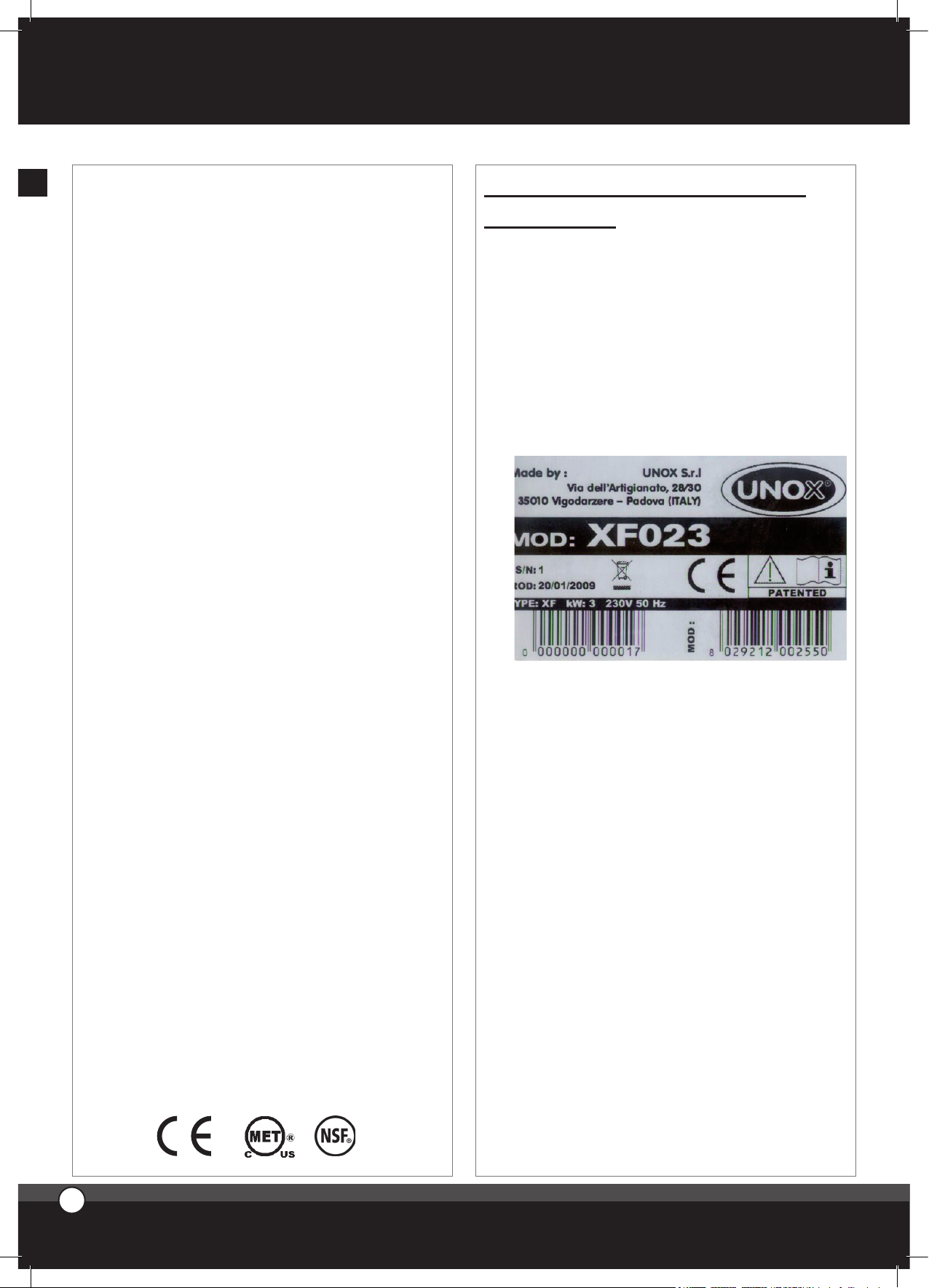
1. DATA PLATE
2. CERTIFICATION
The “CE” brand you find on our labels and on our user
manual refers to the following directives:
ELECTRIC CONVECTION OVENS - SERIES XF:
• Low Tension Directive DBT EC 2006/95,
according to rule EN60335-2-42+A1 and according to
rule EN60335-2-46+A1
• Electromagnetic Compatibility Directive EC 2004/108,
according to rules EN6555-3, EN55014 and EN55104.
The ovens of the XAF series carry MET and NSF for
U.S.A.
INDEX
I. Instructions for the installer
1. DATA PLATE
2. CERTIFICATION
3. INSTALLATION
- Preliminary operations
4. INSTALLATION
- Electrical connection
II. Instructions for the user
1. INSTRUCTION FOR THE OPERATOR
2. NOTES FOR THE USE
3. CONTROL PANEL
4. CLEANING OF THE OVEN
5. TURNING OFF IN CASE OF BREAKDOWN
III. Cooking principles
1. COOKING TYPOLOGIES
2. COOKING VARIABLES
3. USE OF PANS - GRIDS
IV. Maintenance
1. ORDINARY MAINTENANCE
2. SPECIAL MAINTENANCE
3. MORE FREQUENT BREAKDOWNS
Page 3
3. INSTALLATION
PRELIMINARY OPERATIONS
All the electrical connections and installation operations
must be done by qualified personnel according to actual
laws.
3.1 CHECK THE LOCATION OF INSTAL
LATION
Before placing the appliance, please verify the overall
measurements and the exact position of the electrical and
water connections looking at the pictures on the attached
file “TECHNICAL DATA”.
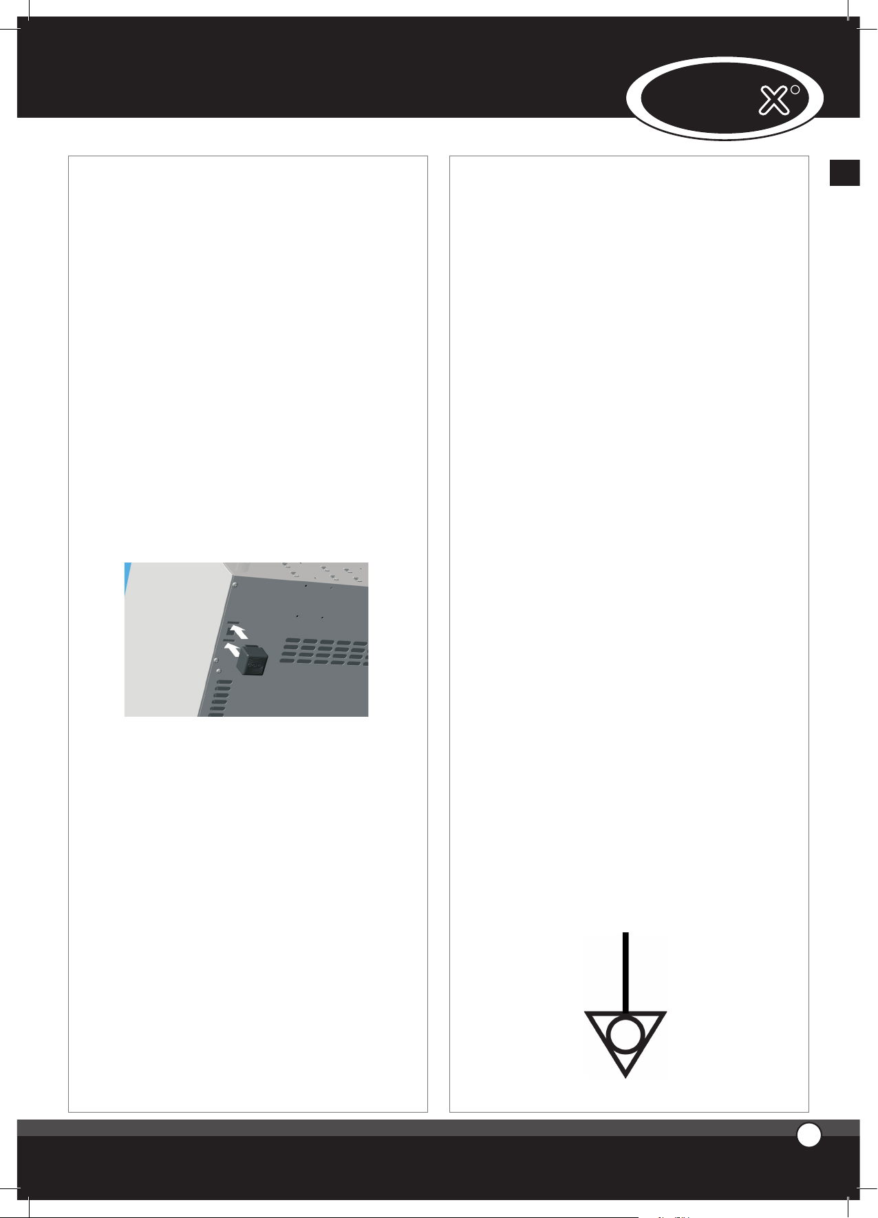
3.2 FEET ASSEMBLY
You find the feet inside the appliance. The feet must
absolutely be assembled on the oven.
Do not ever use the appliance without its feet.
Assemble the feet as showed in picture:
3.3 POSITIONING
Place the appliance respecting the safety standards in
force that you find here following described.
Place the appliance so that its back and sides can be easily
reached in order to make the electrical connections and
provide the needed service.
The appliance is not suitable for built-in installation and
side by side positioning, therefore, in case of use of more
than one oven, the appliances can not to be stacked.
It is suggested to leave a distance of 10 cm. Between the
eventual wall on the back of the oven and the chimney.
With particular reference to the ovens, all models must
be placed upon a support, for example a prover, a stand
or on the top of a table built with non-combustible mate-
rial.
Never install the appliance on the floor.
If the appliance is placed near walls, dividers, kitchen cabinets, decorated edges, etc., it is recommended that this
be of non combustible material.
Otherwise, they must be coated with non combustible
thermal insulating material and you must be very respectful of the fire prevention standards.
3.4 REMOVE THE PROTECTIVE FILM
Carefully remove all the protective film from the exter-
nal walls of the appliance. Pay attention not to leave any
rest of glue on the sides.
If there should be any residue, please remove it with an
appropriate solvent (ex.: ethyl denatured alcohol).
4. INSTALLATION ELECTRICAL CONNECTION
a-The connection to the electrical power supply system
must be done according to the standard in force.
Use the oven at a room temperature between +5 °C and
+35 °C.
Before connecting the appliance, make yourself sure that
the voltage and the frequency correspond to those stated on the data plate of the appliance. The appliance must
be placed so that the connection plug to the network can
be easily reached.
Place an omni-polar switch between the appliance and
the network. The switch must be easily accessible after
installation. The contacts of this switch must have a minimum opening distance of 3 mm and the switch must have
an appropriate input. It is suggested to use a differential
magneto-thermal switch.
When the appliance is working, the power supply voltage
must not diverge from the value of the nominal voltage,
written on the technical data plate, by more than ± 10%.
The protective cover of thermal cut out should be tight so
cannot be removed without the use of a tool.
b- The appliance must be connected to the ground line of
the network.
Moreover, the appliance must be included in an equipo-
tential system whose efficiency must be properly checked
according to the current law. This connection must be
done between the different appliances using the terminal
marked with the symbol:
ENGLISH
3
2
ENGLISH
UNO
R
2
Page 4
The equipotential conductor must have a minimum sec-
tion of 10 mm2.
1- Ovens equipped with cordset and Schuko plug (single
phase 230V) or Nema pyug ) single pfare 120 or 230 v.):
is sufficient to insert the plug in the proper socket (the
socket must be suitable for the plug assembled in the
oven)
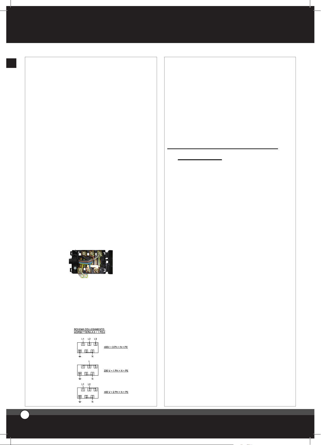
2- Ovens equipped with cordset (three phases 400V + Neu-
tral): these ovens are equipped with electrical cord with 5
conductors: it is necessary to connect the proper threephase 5 poles plug with suitable capacity or you can connect the cord directly to the electrical panel.
In those ovens equipped with a cord with 5 conductors it
is possible to substitute the power cord to adapt the appliance to the available type of current.
To replace the power cord proceed as follows:
• Open the cover of the terminal board levering the two
lateral small wings with a proper screw-driver (1)
• Unscrew the screws that lock the conductors (2)
• Unscrew the screw that locks the cordstopper (3)
• Remove the supplied cord
• Connect the conductors that you would like to use according to the chosen connection drawing; be sure to fix
properly the screws of the clamps.
• Block the cord using the proper cordstopper
• Close the cover of the terminal board.
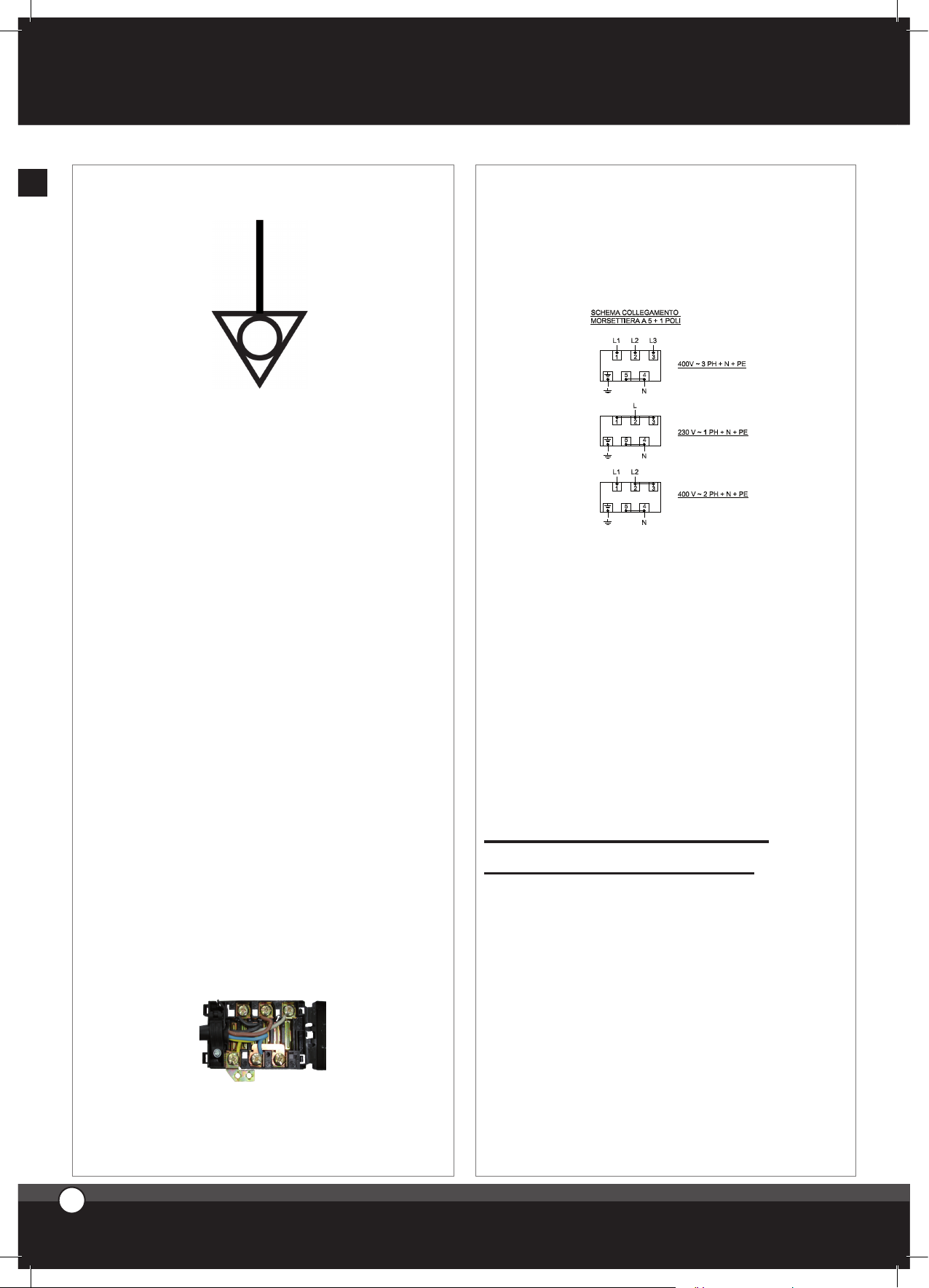
WARNING:
Connect the electrical cable to the terminal board as shown on
the drawing: insert screw-wise the copper bridge and the electrical cable together under the screw. Tighten the screw paying
attention that the cable and the copper bridge are well fixed
under the screw. A wrong connection can cause the overheating of the terminal board which can also melt.
FUMES EXIT FROM CAVITY
In the back side of the oven you find a fume chimney from
which the fumes that come from the cavity are ejected.
During each cooking cycle you will have hot and wet fumes
coming out from this chimney (temperature and humidity
of the fumes depend on the cooking parameters set on the
oven and on the type and quantity of food put inside the
oven).
The fumes that come out from the chimney can be guided
outside the room where the oven is installed or can be
condensated.
11. INSTRUCTIONS FOR
THE USER
The appliance cannot be cleaned with a jet of water.
Never wash the cavity with acids or aggressive detergents. Use only water and soap.
The appliance is made for a specific professional use and
must be used by qualified personnel only.
1. INSTRUCTIONS FOR THE OPERATOR
WARNING: carefully read this user manual befo-
re starting to operate with the appliance as it gives
you important information regarding safety during
installation, use and maintenance of the appliance
itself.
Keep the manual in a safe place where the different operators that work with the appliance can easily find and read it.
Before using the appliance for the first time ensure that
inside the cooking chamber there are no instruction manuals, plastic bags or any other objects.
The appliance is not intended to be used by persons with
reduced mental, physical and sensory capacities (children
included), or without any expertise and know-how, unless they are informed about how to use the equipment
or they operate under the supervision of who is responsible for their safety.
Children should be watched to make sure they do not
play with the equipment.
For any eventual repair, please apply only to authorized service centres. Always require original UNOX spare parts.
Failure to observe the above suggestions can compromise safety of the appliance and the guarantee
will not be recognized anymore.
4
3
ENGLISH
LineMicro™
Page 5
2. NOTES FOR USE
In case you need to open the door while the oven is
working, it is suggested to open it completely in order
to let the heat coming easily out of the cooking chamber,
avoiding to damage the lateral columns
This appliance must be used only in the way in which
it was expressly intended. The ovens were designed to
cook food as here below described. Every other use is to
be considered improper.
The oven allows you to work on temperature between 0
and 300 °C (0 - 572 °F). It can be used to:
• bake all types of bread and pastry, both fresh and fro
zen;
• cook all gastronomy preparations, fresh or frozen;
• regeneration of refrigerated or frozen food;
•cook meat, fish and all kind of vegetables.
When placing the food in the cooking chamber, leave at least 20 mm between the trays in order to
allow the hot air to circulate inside the cavity.
Please avoid to put salt on the food inside the cavity
3. CONTROL PANEL
COOKING TIME SETTING
Time of cooking can be set by turning clockwise the knob
situated on left side of the control board:
time range is 0 - 60 minutes.
By turning the knob anti-clockwise the oven works continuously.
By turning the knob you start the oven: the fan spins and
internal light, if present, turns on.
When cooking time is over, the knob turns to “0” positio-
nand the oven turns off.
Attention! The oven is off when the timer knob is set at
zero “0”. To check the oven is correctly turned off, wait 5
minutes before leaving the equipment unattended.
4
ENGLISH
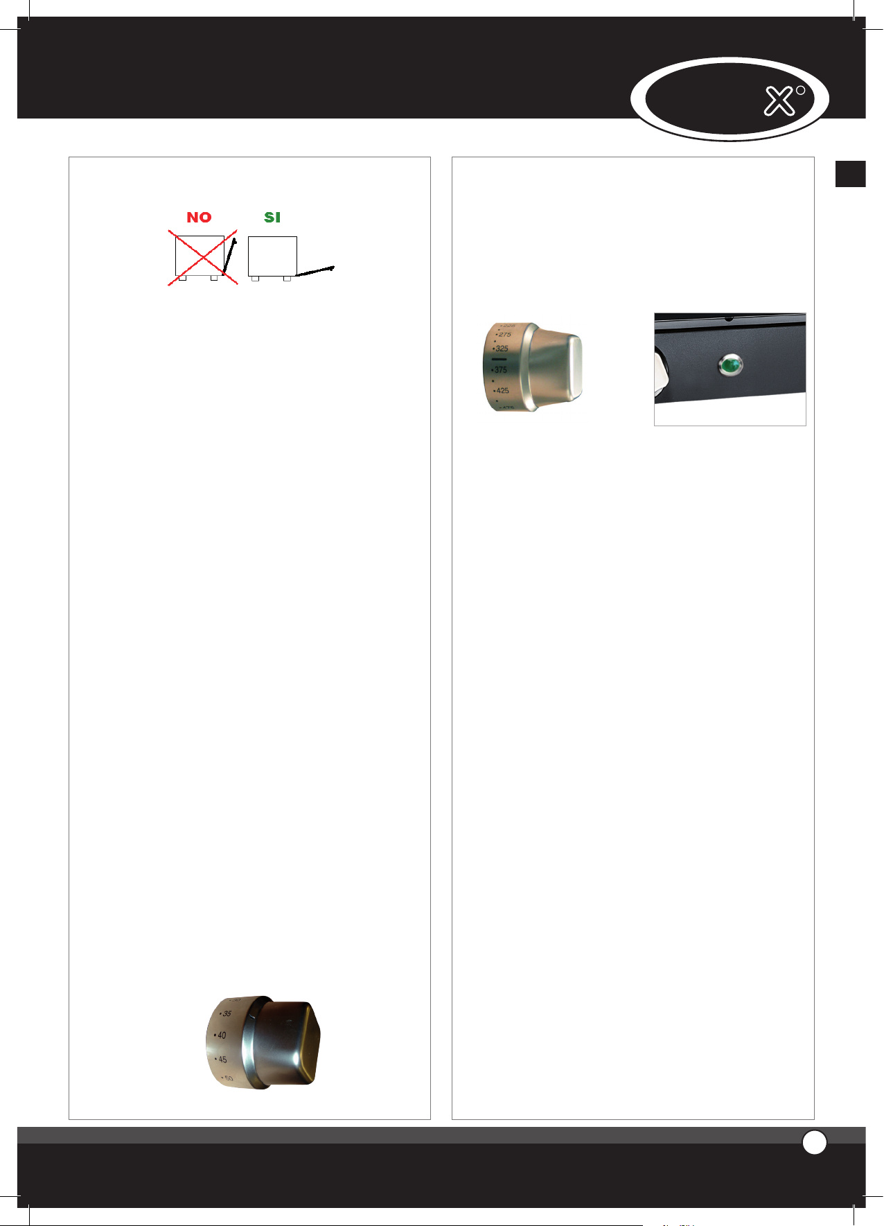
COOKING TEMPERATURE SETTING
The cooking temperature inside cooking chamber is set through the temperature knob (on right side of control board): temperature range is 0 - 300 °C (0 - 572 °F).
Temperature green light on indicates that heating element is
on; when set temperature is reached turns off.
4. CLEANING
WARNING:
Before starting any maintenance or cleaning operation it is necessary to disconnect the electrical power
supply and wait for the appliance to cool down.
4.1 FIRST USE OF THE OVEN
Before the first use of the appliance: clean the metal part
with hot water and soap and rinse it. Never wash the inner
part of the oven with acids or aggressive detergents.
With the empty cavity, heat the oven up for about 30 min-
utes at a temperature of 200 °C (392 °F) to eliminate any
thermic insulation smell.
4.2 CAVITY CLEANING
At the end of each cooking cycle, clean the cavity using only
proper products.
Never clean the stainless steel with acids, aggressive deter-
gents or other product containing chlorine (sodic hypochlorite, hydrochloric acid, etc.), even though they are diluted.
4.3 CLEANING OF THE EXTERNAL PART OF
THE OVEN
Never use a jet of water in pressure to clean the external
part of the oven. Only use wet clothes and proper products
for stainless steel cleaning.
To clean the glass of the oven use water and neutralsoap.
Never use alcohol or other type of solvent.
UNO
R
Page 6
ChefTop™
LineMicro™
5. TURNING OFF IN CASE OF BREAKDOWN
If there is a breakdown, deactivate the appliance:
a- disconnect the electrical power supply automatic circuit
breaker placed upstream from the appliance or, in case of
no circuit breaker, unplug the appliance.
b- consult a technical service centre authorized by the man
facturer where you can find trained personnel.
III. COOKING PRINCIPLE
1. COOKING TYPOLOGIES
The types of cooking you can realize with the appliance
described on this manual are Bread, Pastry professional
baking and Gastronomy professional cooking with CONVECTION, that means the baking is realized through hot air.
WARNING:
a- Before any use, heat up the oven setting a cavity tem-
perature 30 °C (54 °F) higher than the desired cooking
temperature.
This allows you to obtain the best baking uniformity.
b- Use of higher temperatures than those needed by the
product causes an uneven baking.
c- Bread and Pastry baking: do not use trays with a height of
more than 20 mm and avoid that the single units on the
tray get in touch.
d- Do not overload the trays.
In convection ovens the cooking is done by hot air that
circulates round and round inside the cooking chamber.
This allows to realize an even cooking, also because in
this way the heat is homogeneously distributed.
An even baking is guaranteed also when the oven is fully
loaded. The food is perfectly baked both on the surface,
with a golden crust, and in the internal part, with a uni-
form structure and a constant residual humidity.
The main advantage is the possibility to cook at the same
time different types of food without mixing their flavours
( as long as the required cooking temperature is the same
for all the cooked products).
2. COOKING VARIABLES
TEMPERATURE
The exact setting of the temperature grants a proper
cooking of the food, both inside and outside.
A lower temperature than the proper one dries the food
rather than cook it.
A higher temperature than the proper one burns the sur-
face while the core of the food remains uncooked (some-
times this is desired, especially with meat dishes).
TIME
This variable depends a lot on the quantity of food put in
the oven. The bigger the quantity of food, the longer the
cooking time and vice versa.
A shorter cooking time than that required by the food
does not allow to have completely cooked food.
A longer cooking time than that required by the food
causes the burning of the food surface.
QUANTITY OF FOOD
The quantity of food affects the cooking time.
The bigger the quantity of food, the longer the cooking
time and vice versa.
An overload of the oven can give, as a result, an uneven
cooking.
3. USE OF TRAYS – WIRE GRIDS
It is recommended the use of:
• Aluminium trays: Pastry, non-frozen bread
• Stainless steel trays: first courses, meat, fish, potatoes
• Wire grids: meat to be finished such as steaks, hot-dogs,
sausages, frozen bread, frozen pizza
IV. MAINTENANCE
1. ORDINARY MAINTENANCE
All maintenance operations must be done only by quali-
fied personnel.
Before starting any maintenance operation, you need to
disconnect the appliance from the electrical power supply and wait for the appliance to cool down.
The parts that need ordinary maintenance can be reached
removing the front control panel and the back of the oven.
The appliance must be regularly controlled (at least once
a year). A specialized technician has to control the complete machine
2. SPECIAL MAINTENANCE
All maintenance operations must be done only by quali-
fied personnel.
Before starting any maintenance operation, you need to
disconnect the appliance from the electrical power supply and wait for the appliance to cool down.
The parts that need special maintenance can be reached
removing the front control panel and the back of the oven.
2.1 REPLACEMENT OF INTERNAL LAMP (IF
PRESENT)
5
ENGLISH
Page 7
UNO
R
UNO
R
7
6
ENGLISH
To replace the internal lamp, please operate as follows:
• Disconnect the appliance from the power supply system and let it cool down.
• Remove the lateral supports.
• Unscrew the glass cover and replace the lamp with one
with the same characteristics.
• Screw the glass cover back in.
• Reassemble the lateral supports.
2.2 REFIT OF THE SAFETY THERMOSTAT
The appliance is equipped with a safety thermostat with
manual recovery. This safety thermostat is needed to protect the appliance from overheating. In case it is needed,
it turns the appliance off.
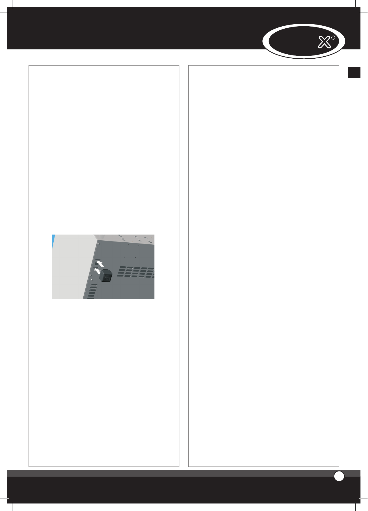
This safety thermostat can be reached removing the black
cap you find on the bottom part of the back of the oven:
in case you need to refit it, push the key you have in the
center of the thermostat so that it starts working again.
3. MORE FREQUENT
BREAKDOWNS
CAUSE SOLUTION
BREAKDOWN
The tension of the electrical
system is missing
Restore the tension
Safety thermostat intervention Refit the safety thermostat
The oven is completely turned
off
The connection to the electrical
system not made in the correct
way
Control the connection of the
appliance to the electrical
system
Damaged door basket Contact a specialized
technician for reparation
There is water coming out of
the cavity from the door
gasket, even though the door
is closed
Loosened door mechanism Contact a specialized
technician for reparation
Burnt lamp Sostituire la lampadina
The oven light (if present) does
not turn on
Loosened lamp Inserire in maniera corretta la
lampadina nel portalampade
The fans do not reverse the
rotating direction
Contact a specialized
technician for reparation
One of the fans do not work (in
case that you have an oven
with more than one motor)
Contact a specialized
technician for reparation
The cooking results are even
The heating element is broken Contact a specialized
technician for reparation
Substitute the lamp
Fix the lamp in the lamp holder cor-
rectly
3. MORE FREQUENT BREAKDOWNS
CAUSE SOLUTION
Page 8

LineMicro™
1
FRANÇAIS
I. LES INSTRUCTIONS
POUR L’INSTALLATEUR
Gentil Client, nous la remercions et nous nous complimentons pour avoir acheté un produit UNOX.
Les avertissements et les conseils qui suivent concernent
les phases pour la correcte installation, l’usage et la maintenance de l’équipement, pour sauvegarder sa sûreté et
pour une meilleure utilisation de l’appareil.
1. ÉTIQUETTE DES DONNÉES
2. CERTIFICATION
Le marquage “CE” rapportée sur les appareillages
insérés dans ce manuel fait référence aux suivantes
directives :
FOURS À CONVECTION ELETTRIQUES-SERIE XF :
• Directive de la Basse Tension
DBT EC 2006/95,
selon la norme EN60335-2-42+A1 et
selon la norme EN60335-2-46+A1
• Directive de la Compatibilité Electromagnétique EC
2004/108,
selon les normes EN60555-3, EN55014, EN55104
Le fours du la series XAF sont approuvé avec MET et
NSF mark.
INDEX
I. Les Instructions pour l’installateur
1. ETIQUETTE DES DONNÉES
2. CERTIFICATION
3. INSTALLATION
- les opérations préliminaires
4. INSTALLATION
- Branchement elettrique
II. Les Instructions pour l’utilisateur
1. INSTRUCTIONS POUR L’UTILISATEUR
2. INDICATIONS D’EMPLOI
3. TABLEAU DES COMMANDES
4. NETTOYAGE DU FOUR
5. ETEIGNEMENT EN CAS DE DEGÂT
III. Les Principes de cuisson
1. TYPOLOGIES DE CUISSON
2. VARIABLES DE CUISSON
3. UTILISATION DES PLAQUES ET DES GRILLES
IV. La maintenance
1. MAINTENANCE ORDINAIRE
2. MAINTENANCE EXTRAORDINAIRE
3. LES DÉGÂTS PLUS FRÉQUENTS
Page 9
3. L’INSTALLATION
- LES OPERATIONS PRÉLIMINAIRES
Toutes les opérations d’installation et de branchement
électrique doivent être faites par des personnes qualifiées
selon les normes en vigueur.
3.1 LA VÉRIFICATION DU LIEU
D’INSTALLATION
Avant de positionner l’appareil vérifiez les mesures d’en-
combrement et l’exacte position des branchements
électriques selon la figure rapportée dans le dossier cijoint «Données Techniques».
3.2 LE MONTAGE DES PIEDS DES FOURS
Les pieds sont posés à l’intérieur de l’appareillage et
doivent être péremptoirement montés. Ne pas utiliser
l’équipement sans les pieds. Insérer les pieds à déclenchement comme montré dans la figure.
3.3 LE POSITIONNEMENT
Positionnez l’appareil en respectant les normes de sûreté
indiquées comme suit:
1. disposez l’appareil en mode que les parties postérieures
et latérales soient facilement accessibles pour effectuer
le branchement électrique e pour permettre la maintenance de l’appareillage.
2. L’appareillage n’est pas adéquat pour être encastrer ou
positionner en batterie.
3. On conseille de laisser une distance de 10 cm entre la
partie postérieure et la cheminée du four.
Tous les modèles doivent être positionnés au dessus d’un
support, pas ex. une étuve, un support ou bien une table
faite par un matériel incombustible.
Non jamais installer les fours sur le sol directement.
Si l’appareil est positionné à coté d’un mur, diviseurs,
meubles de cuisine, bordures décorées etc., on vous recommande que ceux-ci soient faites d’un matériel incombustible.
En cas contraire ils doivent être revêtus avec un matériel
isolant thermique incombustible, et il faut bien sur prêter
l’ attention aux règles de prévention incendie.
3.4 L’ENLÈVEMENT DES FEUILS DE PROTECTION
Enlevez complètement le feuil de protection des parties
externes de l’appareil attentivement et évitez de laisser
des résidus de colle.
Si malgré cela ces résidus persistent, enlevez-les avec un
solvant approprié.
4. L’INSTALLATION
4.1 BRANCHEMENT ELETTRIQUE
a- Le branchement au réseau électrique doit être
effectué par des personnes qualifiées
selon les normatives en vigueur.
Utiliser le four avec une température ambiante comprise
entre +5 °C et +35 °C.
Avant d’effectuer le branchement, contrôlez que la ten-
sion et la fréquence correspondent aux données rapportées sur l’étiquette de l’appareil. L’appareil doit être
positionné de sorte que l’épine de connexion au réseau,
soit accessible.
Interposer entre l’appareillage et le réseau, un interrup-
teur omnipolaire. Cet Interrupteur doit être facilement
accessible après l’installations.
Les contacts de cet interrupteur doivent avoir une dis-
tance minimale d’ouverture de 3mm et il doit avoir aussi
une portée appropriée. On vous conseille d’utiliser un
interrupteur differential magneto-thermal switch.
La tension d’alimentation, lorsque l’appareil est en fonc-
tion, ne doit pas s’écarter de la valeur nominale de la
tension rapportée sur l’étiquette données du four, de
±10%.
Le couvercle de le thermostat du protection doit être
serré ne peut pas êntre enlevé sans l utilisation d-un outil
b- L’appareillage doit être lié à la ligne de terre
du réseau. En outre l’appareillage doit être inclus dans un
système équipotentiel duquel l’efficacité doit être opportunément vérifiée selon combien rapporté dans la réglementation en vigueur.
ENGLISH
3
2
FRANÇAIS
UNO
R
2
Page 10
ChefTop™
Cette liaison doit être effectuée entre les différents appareil-
lages avec la borne marquée du symbole :
Le conducteur équipotentiel doit avoir une section mini-
male de 10 mm2.
1- Fours doués de câble et fiche Schuko (monophase 230V) :
il est suffisant d’insérer la fiche dans l’appropriée prise (la
prise doit être apte à l’épine fournie en dotation).
2- Fours doués de câble (des tri phase 400V Neutre) : les
fours en question sont doués d’un câble électrique à 5
conducteurs : il est nécessaire de relier l’appropriée fiche
tri phase aux 5 pôles de portée appropriée ou bien de
relier le câble directement à un cadre électrique.
Dans les fours doués de câble à 5 conducteurs il est possible
substituer le câble d’alimentation pour adapter le four à la
typologie de fourniture de courant électrique disponible.
Pour substituer le câble d’alimentation procédez
comme il suit :
• Ouvrir le couvercle de la boite à bornes en faisant levier,
avec un tournevis adapté, sur les deux ailettes latérales (1)
• Dévisser les vis de blocage des conducteurs (2)
• Dévisser les vis du fixe-câble (3)
• Ôter le câble en dotation
• Relier les conducteurs du câble qu’on veut utiliser selon
le schéma de liaison choisie en serrant opportunément les
vies des boites à bornes
• Bloquer le câble à travers l’approprié fixe câble
• Enfermer le couvercle de la boite à bornes
PRÉCAUTION :
Effectuer la connexion électrique de la boîte à bornes comme
indiqué dans le dessin: introduire le pont de cuivre et le câble
électrique ensemble sous la vis, dans le sens de vissage, dans la
façon que, en serrant la vis, le câble et le pont soient strictement fixés.
Une connexion incorrecte peut causer le surchauffage de la
boîte à bornes, jusqu’ à la faire fondre.
LA SORTIE DES VAPEURS DE LA CHAMBRE DE CUISSON
Une cheminée d’évacuation des vapeurs provenant
de la chambre de cuisson est présente dans la partie
postérieure du four:
pendant la cuisson, les vapeurs chaudes et humides sortent
à travers cette cheminée (la température et l’humidité
des vapeurs dépendent des paramètres de fonctionnement du four et du type et de la quantité de produit inséré à l’intérieur du four). Les vapeurs qui sortent de la
cheminée peuvent être canalisées vers l’extérieur ou bien
condensées.
II. LES INSTRUCTIONS
POUR L’UTILISATEUR
L’appareillage ne doit pas être nettoyé avec un jet d’eau
en pression. Ne lavez jamais l’intérieur de la chambre de
cuisson avec des acides ou des produits agressifs, mais
seulement avec du savon et de l’eau. L’appareillage est
destiné à l’emploi professionnel spécifique et doit être
utilisé seulement par des personnes qualifiées.
1. LES INSTRUCTIONS POUR
L’UTILISATEUR
ATTENTION!
Lisez attentivement le présent livret puisqu’il vous
fournit des importantes indications en ce qui concerne la sûreté de l’installation, de l’emploi et de la
maintenance.
4
3
FRANÇAIS
LineMicro™
Page 11

UNO
R
Conservez avec soin ce livret pour chaque ultérieure consultation des divers opérateurs.
En phase de première utilisation, faire attention que le
notice d’utilisation, des sacs en plastic ou n’importe quel
autre objet, ne soient pas présents à l’intérieur de la
chambre de cuisson.
L’appareil n’est pas conçu pour une utilisation de part de
personnes (inclus les enfants) avec des capacités mental,
physique et sensoriales réduites, ou une absence de expérience ou de connaissance de l’appareil, au moins q’îles
sont surveillées par une personne responsable pour la
leur sécurité ou qui louer donne des instructions pour
l’utilisation de l’appareil.
Les enfants doit être surveillées, pour être sur que il ne
jeux pas avec l’appareil.
Pour une éventuelle réparation il faut s’adresser seulement à un centre d’assistance technique et exiger des
pièces détachées UNOX originales.
Le non- respect de ce qui est écrit là-dedans peut
compromettre la sûreté de l’appareillage et vous
risquez d’être déchus de la garantie.
2. NOTE POUR L’USAGE
L’appareillage devra être destiné seulement à l’emploi
pour lequel il a été expressément conçu.
Les fours ont été projetés pour la cuisson « au four » des
aliments comme rapporté ci-dessous. On retient impropre chaque autre emploi.
Le four vous permet des températures d’exercice comprises entre 0 - 300 °C (0 - 572 °F).
Vous pouvez l’utiliser pour :
• Les cuissons de tous les produits de la pâtisserie et du
pain, frais ou congelés.
• Les cuissons de tous les produits de la gastronomie,
frais ou congelés.
• Pour le reconditionnement des aliments réfrigérés et
congelés.
• Pour la cuisson de la viande, des poissons et des verdures.
En disposant les aliments dans la chambre de cuisson, laissez une espace d’au moins 20 mm entre
les bassinets pour permettre la circulation de l’air
chaud.
Évitez de saler les aliments dans la chambre de cuisson.
4
FRANÇAIS
3. LE TABLEAU DES COMMANDES
L’ETABLISSEMENT DU TEMPS DE CUISSON
On établit le temps de cuisson au moyen de la poignée
destinée à cet usage (poignée à gauche sur le tableau des
commandes): le temps peut être établi entre 0 - 60 min.
En tournant la poignée en sens horaire, on établit le temps
de cuisson; en tournant la poignée en sens contraire aux
aiguilles d’une montre (position manuelle), le four fonctionne sans arrêt.
La rotation de la poignée fait partir le four en activant la
rotation des turbines et en allumant la lumière interne (si
présente).
Attention! La condition du four éteint se vérifie seulement quand la poignée du Timer est mise exactement à
zéro “0”. Pour être sûr de l’éteignement correcte du four,
il faut attendre 5 minutes avant de laisser l’appareil.
L’ETABLISSEMENT DE LA TEMPERATURE DE CUISSON
On établit la température de cuisson au moyen de la
poignée destinée à cet usage (poignée à droite sur le
tableau des commandes):
la température peut être établie entre 0 - 300 °C (0 - 572 °F) .
Feu vert de la température lorsque qu’il est allumé, signale
que la résistance est active; quand la température désirée
est rejointe s’éteint.
4. LE NETTOYAGE DU FOUR
NOTICE:
Avant d’effectuer n’importe quelle intervention
d’entretien ou nettoyage, débranchez l’alimentation
électrique et attendez le refroidissement de
l’appareil.
UNO
R
Page 12

ChefTop™
LineMicro™
4.1 LA PREMIÈRE UTILISATION DU FOUR
Avant d’utiliser l’équipement pour la première fois il est
obligatoire nettoyer la partie interne en métal avec de
l’eau chaude et du savon et ensuite la rincer bien.
Ne lavez jamais l’intérieur de la chambre avec des acides
ou des produits agressifs.
Il est nécessaire ensuite réchauffer l’appareil à vide pour 3
minutes environ à la température de 200 ºC (392 ºF) pour
éliminer des éventuelles odeurs causées par l’isolation
thermique.
4.2 LE NETTOYAGE DE LA CHAMBRE DE
CUISSON
Il est nécessaire nettoyer l’intérieur de la chambre de cuis-
son en utilisant des produit adéquats à la fin de chaque
cycle de cuisson.
N’utilisez pas pour le nettoyage de l’acier des acides, des
produits agressifs ou bien des produits qui contiennent le
chlore (hypochlorite sodique, acide chlorique etc.), néanmoins s’ils sont dilués.
4.3 LENETTOYAGE EXTERNE DU FOUR
On vous recommande de ne pas utiliser un jet d’eau en
pression pour le lavage extérieur du four. Utilisez seulement des tissus humides et des produits convenables
pour le nettoyage de l’acier inoxydable .
Pour nettoyer le vitre du four, utilisez de l’eau avec
du savon neutre. Ne jamais utiliser de l’alcool ou bien
d’autres types de produits.
5. L’EXTINCTION EN CAS DE DÉGÂT
En cas de dégât vous êtes priés de désactiver
l’appareillage :
•débrancher l’interrupteur automatique de l’alimentation
électrique.
•s’adresser à un centre d’assistance technique ayant un
personnel qualifié.
III. LES PRINCIPES DE
CUISSON
1. LES TYPOLOGIES DE CUISSON
Les typologies de cuisson qui peuvent être effectuées
avec les équipements indiqués dans ce manuel sont la
Cuisson Professionnelle de Pain et Pâtisserie et la Cuisson
Professionnelle de la Gastronomie en modalité à CON-
VECTION, c.à.d à travers la circulation de l’air chaud.
PRÉCAUTION :
a- Réchauffez le four en fixant une température supérieure
à la température de cuisson de 30°C (54°F) avant toute
utilisation pour obtenir une cuisson uniforme.
b- L’utilisation de températures plus élevées par rapport au
standard demandé d’un produit cause une cuisson non
pas uniforme.
c- Pour la cuisson du pain et de la pâtisserie: n’utilisez pas
des plaques avec une hauteur supérieure à 20 mm et
évitez que les produits placés sur la plaque se touchent.
d- Ne surchargez pas les plaques de produit.
Dans les fours à Convection (fours à air pulsé), la cuis-
son se produit à travers la circulation de l’air chaud à
l’intérieur de la chambre de cuisson. Ceci permet de cuisiner les aliments uniformément grâce à une distribution
homogène de la température.
L’uniformité de cuisson est garantie même si le four est
complètement chargé.
Le produit est cuit parfaitement que se soit en superfi-
cie, avec une dorure homogène, ou bien dans la partie
interne, avec une structure uniforme et une humidité restante constante.
L’avantage se présente dans la possibilité de pouvoir cuire
en même temps des produits de nature différente (pourvu que la température de cuisson soit la même) sans mélanger les saveurs.
2. LES VARIABLES DE CUISSON
LA TEMPÉRATURE
L’exacte position de la température garantit une cuisson
correcte des aliments que se soit dans la partie externe
ou bien dans la partie interne.
• Une température basse par rapport à celle correcte
tend plus à dessécher qu’à cuire la nourriture.
• Une température supérieure à celle correcte tend à
brûler la partie extérieure et à laisser l’intérieur non cuit
(ce phénomène parfois est voulu par exemple dans la cuisson de la viande).
LE TEMPS
Cette variable dépend beaucoup de la quantité des ali-
ments introduite dans le four. Les temps de cuisson
s’allongent quand les quantités augmentent et vice-versa.
Des temps plus courts par rapport à ceux correctes ne
permettent pas une cuisson complète des aliments.
Des temps plus longs, toujours par rapport à ceux cor-
rectes, créent des phénomènes de brûlure extérieure des
aliments.
5
FRANÇAIS
Page 13

UNO
R
UNO
R
7
6
FRANÇAIS
LA QUANTITÉ DES ALIMENTS
La quantité des aliments influence le temps de cuisson.
Des quantités majeures signifient des temps de cuisson
plus longs et vice-versa. Une quantité des aliments excessive peut provoquer une aggravation de l’uniformité de
cuisson.
3. L’UTILISATION DES PLAQUES – GRILLES
On vous conseille d’utiliser des:
•Plaques en aluminium: pâtisserie, pain non surgelé.
•Plaques en acier: premiers plats, viandes, poissons,
pommes de terre
•Grilles: pour rissoler la viande comme les biftèques,
würstel, saucisse, pain surgelé, pizza surgelée.
IV. LA MAINTENANCE
1. LA MAINTENANCE ORDINAIRE
N’importe quelle opération d’entretien doit être ef-
fectuée seulement par des personnes qualifiées. Avant
d’effectuer n’importe quel type d’entretien il est nécessaire débrancher l’alimentation électrique et attendre le
refroidissement de l’appareil.
Les composants qui nécessitent d’entretien ordinaire
sont accessibles en enlevant le tableau des commandes
frontal et le dos du four.
Périodiquement (au moins une fois par an), soumettre
l’appareillage à un contrôle total de la part d’un technicien
spécialisé.
2. LA MAINTENANCE EXTRAORDINAIRE
N’importe quelle opération d’entretien doit être ef-
fectuée seulement par des personnes qualifiées. Avant
d’effectuer n’importe quel type d’entretien il est nécessaire débrancher l’alimentation électrique et attendre le
refroidissement de l’appareil. Les composants qui nécessitent d’entretien ordinaire sont accessibles en enlevant le
tableau des commandes frontal et le dos du four.
2.1 LE REMPLACEMENT DE LA LAMPE
D’ÉCLAIRAGE (SI PRÉSENTE)
Pour substituer la lampe d’éclairage, procédez comme
il suit :
•Débranchez électriquement l’appareillage et laissez-le
refroidir.
•Enlevez les grilles latérales.
•Dévissez le couvercle en verre et substituez la lampe
par une autre ayant les mêmes caractéristiques.
•Revissez le verre ( couvre lampe ).
•Remontez les grilles latérales.
2.2 LE RÉÉQUIPEMENT DU DISPOSITIF
THERMIQUE DE SICURITÉ
L’appareillage est doué d’un dispositif thermique
d’interruption à rééquipement manuel pour la protection contre les sur températures. Dans le cas
d’intervention il éteint l’appareillage. Tel dispositif est
accessible en enlevant le bouchon noir posé en bas dans
le côté postérieur de l’équipement : en cas de rééquipement manuel, pressez le bouton au centre du dispositif
pour réactiver l’appareillage.
DÉGÂT CAUSE SOLUTION
Manque de tension du
réseau électrique
Rétablir la tension
d’alimentation
Intervention du dispositif
thermique de sécurité
Rétablir le dispositif
thermique de sécurité
Le four est
complètement éteint
Branchement au réseau
électrique fait
incorrectement
Vérifier le branchement
au réseau électrique
Joint endommagé Il faut s’adresser à un
technicien spécialisé
pour la réparation
Avec la porte fermée,
l’eau sort à travers le
joint
Système de fermeture
endommagé
Il faut s’adresser à un
technicien spécialisé
pour la réparation
Lampe brûlée Remplacez la lampe
Lumière du four (si
présente) est éteinte
Lampe détendue et pas
bien fixée
Insérer correctement la
lampe dans le porte-lampe
Les Turbines n’effectuent
pas l’inversion de marche
Il faut s’adresser à un
technicien spécialisé
pour la réparation
Un des turbines ne
fonctionne pas ( au cas où
le four a plus d’un moteur)
Il faut s’adresser à un
technicien spécialisé
pour la réparation
La cuisson n’est pas
uniforme
La résistance est
endommagée
Il faut s’adresser à un
technicien spécialisé
pour la réparation
3. LES DEGÂTS PLUS FRÉQUENTS
Page 14

LineMicro™
1
DEUTSCH
I. ANLEITUNG FÜR DEN
INSTALLATEUR
Lieber Kunde, wir möchten Ihnen zu dem Erwerb eines
LineMicro™ Heissluftofens gratulieren und danken.
Achtung: Lesen Sie bitte vor dem Gebrauch, die Bedienungsanleitung gründlich durch. Bewahren Sie die Bedienungsanleitung bitte sehr sorgfältig auf.
1. TYPENSCHILD
2. ZERTIFIKAT
Das CE-Kennzeichen an den Geräten und in
dieser Betriebsanleitung unterliegen den folgenden
EG –Richtlinien:
ELEKTRO HEISSLUFTÖFEN - SERIE XF:
- Niederspannungsrichtlinie
DBT EC 2006/95,
nach EN60335-2-42+A1 und
EN60335-2-46+A1
- Richtlinie der Elektromagnetischen Verträglichkeit
2004/108/CE,
nach EN6555-3, EN55014 und EN55104.
Die Öfen der XAF-Serie von MET und NSF für U.S.A.
INDEX
I. Anleitung für den installateur
1. TYPENSCHILD
2. ZERTIFIKAT
3. INSTALLATION
- Erste schritte
4. INSTALLATION
- Elektrischer anschluß
II. Hinweise für den Benutzer
1. HINWEISE FÜR DEN BENUTZER
2. ANWEISUNGEN FÜR DEN BETRIEB
3. BESCHREIBUNG UND ANWENDUNG DES BEDIENPANELS
4. REINIGUNG DES OFENS
5. ANWEISUNGEN BEI STÖRUNGEN
III. KOCHMETHODEN
1. BETRIEBSARTEN
2. EINSTELLUNG DER PARAMETER
3. GEBRAUCH VON BLECHEN UND ROSTEN
IV. Wartung
1. GEWÖHNLICHE WARTUNG
2. SPEZIELLE WARTUNG
3. STÖRUNGEN UND DEREN BEHEBUNG
Page 15

UNO
R
7
2
DEUTSCH
3. INSTALLATION
ERSTE SCHRITTE
Alle elektrischen Anschlüsse und Installationsarbeiten
müssen von qualifizierten Fachleuten entsprechend den
Richtlinien ausgeführt werden.
3.1 ÜBERPRÜFUNG DER AUFSTELLUNGS-
FLÄCHE
Vor der Aufstellung des Gerätes überprüfen Sie bitte die
Abmessungen und die Position des Elektrischen Anschlusses etc. unter Berücksichtigung der nachfolgenden Seiten
“TECHNISCHE DATEN“.
3.2 MONTAGE DER GERÄTEFÜßE
Die Füße liegen innen im Gerät und müssen unter dem
Ofen angeschraubt werden.
Bitte nutzen Sie das Gerät niemals ohne Füße.
Montage wie im Bild abgebildet.
3.3 POSITIONIERUNG
Das Gerät muss entsprechend den Sicherheitsvorschrif-
ten und Normen wie nachfolgend
beschrieben, aufgestellt werden.
Die Seiten und Oberflächen des Gerätes müssen so auf-
gestellt werden, sodass ein einfacher
elektrischer Anschluss, die normale Wartungen und
Reparaturen möglich sind.
Das Gerät ist nicht einbaufähig, und nicht für Reihenauf-
stellung geeignet.
Es ist wichtig, dass ein Abstand von mindestens 10 cm
zwischen der Geräte Oberfläche bzw.
dem Abluftkamin des Gerätes und der nächsten Möbel
oder dem nächsten Gerät gewährleistet ist.
Alle Geräte müssen auf einem Unterbau, Gärschrank
oder einem geeigneten Tisch aufgestellt
werden. Bitte auf keinen Fall den Ofen auf den Boden
stellen.
Falls das Gerät in der Nähe von Mauern, Wänden,
Küchenschränken, Deko-Materialien aufgestellt werden
muss, ist es wichtig dass diese Teile aus einem nicht brennbaren Material bestehen.
Bitte prüfen Sie dies genau, falls die Teile aus brennbarem
Material bestehen, verkleiden Sie diese mit nicht brennbarer Isolierung oder entfernen Sie diese Teile aus dem
Umfeld des Gerätes. Bitte prüfen Sie hier den Schutzvorschriften vor Feuer und Rauch genau.
Andernfalls, müssen diese mit nicht brennbarem Material
abisoliert werden.
Bitte beachten Sie die Feuerschutzvorschriften.
3.4 ABZIEHEN DES SCHUTZFILMS
Ziehen Sie unbedingt den weißen Schutzfilm von den
Außen und Innenseiten des Gerätes ab, Dies ist wichtig
um ein verbrennen des Schutzfilms während des Betriebes zu verhindern!
Falls ein Rückstand verbleibt, entfernen Sie den Rück-
stand mit einem Lösungsmittel.
4. INSTALLATION
ELEKTRISCHER ANSCHLUß
a- Die Installation zum Stromversorgungsnetz muss vom
qualifizierten Personal gemacht werden und sie muss den
Vorschriften des Netzbetreibers vor Ort entsprechen.
Der Ofen sollte nur bei einer Raumtemperatur von +5
bis +35°C genutzt werden.
Der Installateur ist für den richtigen elektrischen An-
schluss des Ofens und der Beachtung der Sicherheitsnormen verantwortlich.
Vor dem Anschluss stellen Sie bitte sicher das die Voltzahl
und die Stromfrequenz des Stromnetzes mit den Angaben auf dem Typenschild des Gerätes übereinstimmen.
Plazieren Sie den Stecker zwischen dem Gerät und dem
Stromversorgungsnetz nach der Installation, die Kontakte dürfen nur ein Minimum Öffnungs- Abstand von
3 mm von der Zuleitung (z.B.: ein magnetthermischer
Trennschalter).
Wenn das Gerät arbeitet darf die Spannung nicht mehr als
± 10 % von der normalen Spannung abweichen.
b- Das Gerät muss über das Stromnetz geerdet sein.
Zusätzlich muss das Gerät an ein System für einen Äqui-
potential Ausgleich angeschlossen sein.
Der Anschluss für den Äquipotential Ausgleich ist durch
Page 16

ChefTop™
LineMicro™
3
DEUTSCH
dieses Symbol gekennzeichnet:
Die Aquipotential Ausgleichsleitung muss einen Quer-
schnitt von 10 mm2 haben.
1- Ofen mit Zuleitungskabel und Schukostecker (Eine Phase
230 Volt): es ist ausreichend, nur den Stecker in die Steck-
dose zu stecken (der Stecker muss zu der Steckdose pas-
send sein)
2- Ofen mit Zuleitungskabel (drei Phasen 400V): diese Öfen
haben ein elektrisches Zuleitungskabel mit 5 Leiter:
es ist notwendig, den dreiphasigen Starkstromstecker an-
zuschließen oder das Kabel direkt anschließen.
In den Öfen, die ein elektrisches Zuleitungskabel mit 5
Leitern haben, ist es möglich das Kabel auszuwechseln,
und dem verfügbaren elektrischen Strom anzupassen.
Die Auswechslung der elektrischen Kabel( im Fall eines
Kabelschadens) muss durch einen technischen Fachmann
oder durch eine Person die ähnliche Qualifikationen bes-
itzt, vorgenommen werden.
Um die Stromzuleitung auszuwechseln, verfahren Sie wie
folgt:
• Schrauben Sie die Plastikabdeckung der Anschlussleiste mit
einem Schraubenzieher ab(1).
• Schrauben Sie die Befestigungsschrauben der Stromleiter(2) ab.
• Lösen Sie die Befestigungsschraube der Zugentlastung ab (3).
• Entfernen Sie das Kabel.
• Verbinden Sie die Leiter wie auf dem gewählten Schema
beschrieben.
• Befestigen Sie das Kabel durch die Zugentlastung.
• Montieren Sie die Plastikabdeckung der Anschlussleiste
HINWEISE:
Nehmen Sie die Verbindung des Elektrokabels nach der Zeichnung vor:
stecken Sie die Kupferbrücke und den Stromleiter unter die Schraube.
Die Kabel müssen in die Richtung der Verschraubung ange
-
bracht werden, so dass beim Verschrauben der Schraube, der
Stromleiter und die Kupfer-Brücke festgemacht werden:
eine falsche Verbindung kann die Überhitzung der Klemmleiste
bis auf das Schmelzen bewirken.
ABLUFT AUS DEM BACKRAUM
Auf der Rückseite des Ofens finden Sie ein Abluftrohr, aus
welchem die Backraumabluft entweicht. Während eines
Backvorgangs entsteht kontinuierlich Abluft (Hitze und
Beschwadung, abhängig von den Einstellungen und der
Menge der zubereitenden Gerichte).
Die entstehende Abluft kann aus dem Raum abgeführt
werden.
II. HINWEISE FÜR DEN BE-
NUTZER
Dies Gerät ist nicht für die Reinigung mit einem Dampfstrahler geeignet.
Reinigen Sie die Backkammer mit Wasser und Spülmittel,
bitte benutzen Sie keine aggressiven
Reinigungsmittel oder Säuren.
Das Gerät ist speziell entwickelt für die gewerbliche Nutzung in Großküchen, Bäckereien, und muss vom qualifizierten Personal bedient werden.
1. ANWEISUNGEN FÜR DEN BETRIEB
HINWEIS: Bitte lesen Sie gründlich die Bedienun-
gsanleitung, bevor Sie das Gerät in Betrieb nehmen.
Bewahren Sie die Anleitung an einem Platz auf, wo jeder Bediener des Gerätes drauf Zugriff hat.
Vor der ersten Inbetriebnahme des Gerätes vergewissern
Sie sich bitte, dass alles aus dem Garraum entfernt wurde.
Dieser Apparat kann nicht von Leute (und Kinder auch)
mit Kapazitaetsabbau (geistig, koerperlich und sensor-
Page 17

UNO
R
UNO
R
7
4
DEUTSCH
isch), oder ohne Erfahrung und Erkenntniss benutzt sein.
Die Kinder muessen beaufsichtigt sein, damit sie spielen
nicht mit dem Apparat.
Für etwaige Reparaturen rufen Sie nur den vom Werk
autorisierten Kundendienst an und verwenden Sie nur
Original UNOX - Ersatzteile für das Gerät.
All diese Hinweise gewährleisten den sicheren
Gebrauch des Gerätes und die Gültigkeit der Garantie.
2. NOTIZEN ZUR BEDIENUNG
Das Gerät darf nur für den Verwendungszweck für den es
konstruiert wurde, benutzt werden.
Der Verwendungszweck für die Geräte das Backen und
wie weiter unten angegeben.
Für eine andere Nutzung ist das Gerät ungeeignet.
Der Ofen erlaubt Betriebstemperaturen von (0 -300 °C
oder 0 - 572 °C) . Es kann verwendet werden für:
• alle Brot - und Backwarenprodukte, frisch oder gefroren
• Kochen von allen Gastronomieprodukten, frisch oder
gefroren
• regenerieren von gekühlten oder gefrorenen Speisen
• Kochen von Gemüse, Kartoffeln, Fisch und Fleisch.
Wenn Sie die Lebensmittel in die Backkammer einführen, lassen Sie einen Abstand von
mindestens 20 mm zwischen den Blechen, um eine
ausreichende Luftzirkulation der Heißluft zu
gewährleisten.
Führen Sie kein Salz in die Speisen in der Backkammer ein.
3. BESCHREIBUNG UND ANWENDUNG
DES BEDIENPANELS
ZEITEINSTELLUNG
Die Backzeit kann durch das Drehen des linken Knopfes im
Uhrzeigersinn von 0 - 60 Minuten eingestellt werden.
Drehen Sie den Knopf gegen den Uhrzeigersinn, stellen Sie
den Dauerlauf ein.
Beim Drehen des Knopfes starten Sie den Ofen: die Lüf-
terräder drehen sich und das Licht im Backraum geht an.
Achtung!! Der Ofen ist ausgeschaltet wenn die Zeitschlatuhr auf „0“ gestellt ist. Mann muss 5 Minuten warten um
sicherzugehen, dass der Oven korrekt abgeschaltet ist, um
die Ausrüstung unbeaufsichtigt lassen zu können.
EINSTELLUNG DER TEMPERATUR
Die Garraumtemperatur (0 -300 °C oder 0 - 572 °C)
können Sie über den Knopf( rechts auf der Bedienung)
einstellen.
Das grüne Temperaturwarnlicht signalisiert den Heizvor-
gang im Backraum.
Sobald die eingestellte Temperatur erreicht ist, schaltet
sich die Heizung.
4. REINIGUNG
HINWEIS:
Unterbrechen Sie vor der Durchführung jeglicher
Wartungs- oder Reinigungsarbeiten die Stromzufuhr zum Gerät und warten Sie ab bis das Gerät abgekühlt ist.
4.1 ERSTE BENUTZUNG DES GERATES
Vor der ersten Inbetriebnahme des Gerätes: Reinigen Sie
die Metallteile mit warmen Wasser und Seife und spülen
Sie gründlich nach.
Bitte verwenden Sie keine chlorhaltigen Reinigungsmittel
oder Säuren.
Heizen Sie das Gerät nun für ca. 30 Minuten mit einer
Temperatur von 200°C (392° F) auf, um eventuelle
störende Gerüche, die von der Wärmeisolierung ent-
standen sind, zu beseitigen.
4.2 REINIGUNG DES BACKRAUMS
Reinigen Sie den Backraum nach Beendigung jedes Back-
vorgangs in nachfolgend beschriebener Weise:
Page 18

ChefTop™
LineMicro™
5
DEUTSCHDEUTSCH
Verwenden Sie zur Reinigung des Stahls keine chlorhalti-
gen Mittel (Hypochlorit, Salzsäure usw.) auch wenn diese
verdünnt sind.
4.3 ÄUßERE REINIGUNG DES OFENS
Für die äußere Reinigung des Ofens, verwenden Sie auf
keinen Fall einen Dampfstrahler.
Reinigen Sie das Gerät mit einem feuchten Tuch.
Zum Reinigen der Glasscheibe, verwenden Sie Wasser
und Seife.
5. ANWEISUNGEN BEI STÖRUNGEN
Schalten Sie das Gerät im Störfall ab:
a- trennen Sie als erstes die Stromzufuhr
b- kontaktieren Sie einen autorisierten, technischen Fach-
mann der Fa. UNOX.
III. KOCHMETHODEN
1. BETRIEBSARTEN
Die Produkte die mit dem Gerät produziert werden kön-
nen finden Sie hier nachfolgend:
• Brot / Brötchen / Backwaren gewerbliches Backen,
gewerbliches Kochen mit Umluft
HINWEIS:
a- Heizen Sie den Ofen vor jeder Benutzung gut auf, bis zum
einer Temperatur über 30 °C (54 °F) höher als die Ko-
chtemperatur, damit erreichen Sie ein gleichmäßiges Back-
ergebnis.
b- Durch die Einstellung einer Temperatur, die höher als der
normale Standard ist, erreichen
Sie kein gleichmäßiges Backergebnis.
c- Backwaren und Snacks: benutzen Sei keine Bleche die
höher als 20 mm sind und lassen Sie einen Abstand
zwischen den Backwaren, damit die nicht verkleben können.
d- Bitte die Bleche nicht überladen
Das Kochen in einem Ofen mit Ventilator ist möglich
durch die Zirkulation der Heißluft in der Backkammer.
Durch die gleichmäßige Wärmeverteilung wird das Ko-
chen von allen Lebensmitteln möglich gemacht.
Die gleichmäßigen Backergebnisse sind garantiert, auch
wenn der Ofen voll beschickt wurde. Die Produkte be-
kommen eine goldene Kruste auf der Oberfläche und
eine gleichmäßige Struktur im inneren Bereich.
Der größte Vorteil ist die Möglichkeit, in der gleichen Zeit
verschiedene Arten von Lebensmitteln ohne Vermischung deren Aromen (solange die erforderliche Temperatur gleich ist)zu produzieren.
2. EINSTELLUNG DER PARAMETER
TEMPERATUR
Die genaue Einstellung der Temperatur gewährleistet eine
ordnungsgemäße Zubereitung der Lebensmittel, sowohl
innerhalb als auch außerhalb.
• Eine niedrigere Temperatur als die benötigte, trocknet
das Produkt aus, anstatt es zu kochen.
• Eine höhere Temperatur als die benötigte, verbrennt
die Oberfläche, während der Kern der Lebensmittel
roh bleibt(manchmal ist dies gewünscht, vor allem bei
Fleisch).
ZEIT
Diese Variable hängt allerdings stark von der Menge der
zubereitenden Produkte. Je größer die Menge der Lebensmittel, desto länger die Zeit und umgekehrt.
Bei einer kürzeren Zeiteinstellung wird das Produkt nicht
fertig gekocht bzw. gebacken.
Eine längere Zeiteinstellung als normal benötigt, verbren-
nt die Oberfläche des Produktes.
MENGE DES PRODUKTES
Die Menge beeinflusst die länge der Back- bzw.Kochzeit.
Je höher die Menge, desto länger die Zubereitungszeit.
Eine Überladung des Ofens, kann zu einem ungleichmäßi-
gen Ergebnis führen.
3. GEBRAUCH VON BLECHEN UND ROSTEN
Es wird empfohlen, der Einsatz von:
• Aluminium Backblech: Snacks, frisches Brot
• Edelstahl Backblech: für erste Zubereitungen, Fleisch,
Fisch, Kartoffeln
• Gitterroste: Steaks, hot-dogs, Wurstwaren, TK-Brot,
TK-Pizza
IV. WARTUNG
1. GEWÖHNLICHE WARTUNG
Jede Wartung muss von einem qualifizierten Fachmann
durchgeführt werden.
Bevor Sie Wartungsarbeiten durchführen ist es notwendig
immer die Stromzufuhr zu trennen. Das Gerät soll vor
den Wartungsarbeiten abgekühlt werden. Die Kompo-
Page 19

UNO
R
UNO
R
7
6
DEUTSCHDEUTSCH
nenten die der Wartung bedürfen befinden sich hinter
dem Kontrollpanel oder sind über die Rückwand des
Gerätes zugänglich. Das Gerät sollte durch den Kundendienst alle 12 Monate einmal gewartet werden.
2. SPEZIELLE WARTUNGEN
Jede Wartung muss von einem qualifizierten Fachmann
durchgeführt werden.
Bevor Sie Wartungsarbeiten durchführen ist es notwendig
immer den Netzstecker zu ziehen und das Gerät Stromlos zu machen. Das Gerät soll vor den Wartungsarbeiten
abgekühlt werden.
Die Komponenten die der Wartung bedürfen befinden
sich hinter dem Kontrollpanel oder sind über die Rückwand des Gerätes zugänglich.
2.1 AUSWECHSELUNG DER GARRAUMBELEUCHTUNG
Gehen Sie zum Austausch der Lampe, wie nachfolgend
beschrieben vor:
• Unterbrechen Sie die Stromzufuhr zum Gerät und lassen Sie das Gerät abkühlen
• Entfernen Sie die seitlichen Einschubleisten
• Schrauben Sie das Schutzglas ab und ersetzten Sie die
Lampe durch eine, die über dieselben
technischen Eigenschaften verfügt.
• Zur Montage, bitte die eben erwähnten Arbeitsschritte
in umgekehrter Reihenfolge vornehmen.
2.2 Reseten des Sicherheitsthermostaten
Einige Geräte sind mit einem manuellen Sicherheitsther-
mostat ausgestattet.
Dieses Thermostat dient zum Schutz vor Überhitzung
und trennt das Gerät vom Netz.
Sollte dieses Thermostat auslösen, muss das kein Zeichen
für einen Defekt sein. Sie finden Es an der Rückseite des
Gerätes im unteren Bereich. Von außen ist eine schwarze
runde Kappe zu sehen. Diese Kappe drehen Sie bitte ab
und drücken den darunter befindlichen Stift wieder ein.
Sollte das Sicherheitsthermostat sehr oft auslösen, liegt
eine Fehlfunktion vor. Sollte dies der Fall sein, wenden Sie
sich an den UNOX Kundendienst.
Bevor Sie Wartungsarbeiten durchführen ist es notwendig immer den Netzstecker zu ziehen und
das Gerät Stromlos zu machen. Das Gerät soll vor den Wartungsarbeiten abgekühlt werden.
Die Komponenten die der Wartung bedürfen befinden sich hinter dem Kontrollpanel oder sind
über die Rückwand des Gerätes zugänglich.
2.1 Auswechselung der Garraumbeleuchtung
Gehen Sie zum Austausch der Lampe, wie nachfolgend beschrieben vor:
- Unterbrechen Sie die Stromzufuhr zum Gerät und lassen Sie das Gerät abkühlen
- Entfernen Sie die seitlichen Einschubleisten
- Schrauben Sie das Schutzglas ab und ersetzten Sie die Lampe durch eine, die über dieselben
technischen Eigenschaften verfügt.
- Zur Montage, bitte die eben erwähnten Arbeitsschritte in umgekehrter Reihenfolge vornehmen.
2.3 Reseten des Sicherheitsthermostaten
Einige Geräte sind mit einem manuellen Sicherheitsthermostat ausgestattet.
Dieses Thermostat dient zum Schutz vor Überhitzung und trennt das Gerät vom Netz.
Sollte dieses Thermostat auslösen, muss das kein Zeichen für einen Defekt sein. Sie finden Es
an der Rückseite des Gerätes im unteren Bereich. Von außen ist eine schwarze runde Kappe zu
sehen. Diese Kappe drehen Sie bitte ab und drücken den darunter befindlichen Stift
wieder ein. Sollte das Sicherheitsthermostat sehr oft auslösen, liegt eine Fehlfunktion vor. Sollte
dies der Fall sein, wenden Sie sich an den UNOX Kundendienst.
3. STÖRUNGEN UND DEREN BEHEBUNG
STÖRUNG
URSACHE LÖSUNG
Es liegt keine Spannung an. Kontrollieren Sie die Sicherung
Sicherheitsthermostat hat
ausgelöst.
Reaktivieren Sie das
Sicherheitsthermostat.
Das Gerät lass sich nicht
einschalten oder hat ohne
ersichtlichen Grund
abgeschaltet.
Die Stromverbindung ist nicht
korrekt hergestellt.
Überprüfen Sie die
Stromverbindung
Defekte Türdichtung
Kontaktieren Sie einen
autorisierten Fachmann
Wasser tritt trotz
geschlossener Tür aus dem
Garraum aus
Defekter Türkontakt.
Kontaktieren Sie einen
autorisierten Fachmann
Defektes Leuchtmittel. Wechseln Sie das Leuchtmittel.
Die Garraumbeleuchtung lässt sich
nicht einschalten.
Lockeres Leuchtmittel. Überprüfen Sie den richtigen Sitz
des Leuchtmittels.
Die Motoren führen keinen
Drehrichtungswechsel durch.
Kontaktieren Sie einen
autorisierten Fachmann
Ein Lüfterrad dreht sich nicht ( bei
mehrmotorigen Geräten).
Kontaktieren Sie einen
autorisierten Fachmann
Das Koch-/ Backergebnis ist
ungleichmäßig.
Ein Heizelement ist defekt.
Kontaktieren Sie einen
autorisierten Fachmann
3. STÖRUNGEN UND DEREN BEHEBUNG
Page 20

1
ITALIANO
I. ISTRUZIONI PER
L’INSTALLATORE
Gentile Cliente, La ringraziamo e ci complimentiamo per
aver acquistato un nostro prodotto.
Le avvertenze e i consigli che seguono riguardano le fasi
per la corretta installazione, l’uso e la manutenzione
dell’attrezzatura, a tutela della Sua sicurezza e per un
miglior utilizzo dell’apparecchio.
1. TARGHETTA DATI
2. CERTIFICAZIONE
La marcatura “CE” riportata sulle apparecchiature inserite in questo manuale fa riferimento alle seguenti direttive:
FORNI CONVEZIONE ELETTRICI - SERIE XF :
• Direttiva Bassa Tensione
DBT EC 2006/95,
secondo la norma EN60335-2-42+A1 e
secondo la norma EN60335-2-46+A1
•Direttiva Compatibilità Elettromagnetica EC 2004/108,
secondo le norme EN60555-3, EN55014 e EN55104.
I forni della serie XAF riportano i marchi MET e NSF per
gli Stati Uniti.
INDICE
I. Istruzioni per l’installatore
1. TARGHETTA DATI
2. CERTIFICAZIONE
3. INSTALLAZIONE
- operazioni preliminari
4. INSTALLAZIONE
- collegamento elettrico
II. Istruzioni per l’utilizzatore
1. ISTRUZIONI PER L’UTENTE
2. NOTE PER L’USO
3. PANNELLO COMANDI
4. PULIZIA FORNO
5. SPEGNIMENTO IN CASO DI GUASTO
III. Principi di cottura
1. TIPOLOGIE DI COTTURA
2. VARIABILI DI COTTURA
3. USO DI TEGLIE - GRIGLIE
IV. Manutenzione
1. MANUTENZIONE ORDINARIA
2. MANUTENZIONE STRAORDINARIA
3. GUASTI PIU’ FREQUENTI
LineMicro™
Page 21

7
2
ITALIANO
3. INSTALLAZIONE
Operazioni Preliminari
Tutte le operazioni di installazione e di allacciamento elet-
trico devono essere fatte da personale qualificato secondo le norme in vigore.
3.1 CONTROLLARE IL LUOGO DI INSTALLAZIONE
Prima di posizionare l’apparecchio verificare le misure
d’ingombro e l’esatta posizione dei collegamenti elettrici
ed idrici secondo le figure riportate nell’allegato fascicolo
“Dati Tecnici”.
3.2 MONTARE I PIEDINI
I piedini sono posti all’interno dell’apparecchiatura e dev-
ono essere tassativamente montati.
Non utilizzare l’attrezzatura senza piedini.
Inserire i piedini a scatto come mostrato nella figura
3.3 POSIZIONAMENTO
Posizionare l’attrezzatura rispettando le norme di sicurezza indicate qui di seguito.
Posizionare l’attrezzatura in modo che la parete posteriore e laterale siano facilmente accessibili per effettuare
l’allacciamento elettrico e per consentire la manutenzione dell’apparecchiatura.
L’apparecchiatura non è adatta all’incasso e al posizionamento in batteria, pertanto, nel caso di utilizzo di più forni, essi non vanno mai sovrapposti.
Si consiglia di lasciare una distanza di 10 cm tra la parete
posteriore e il camino del forno.
Con particolare riferimento ai forni, tutti i modelli devono essere posizionati sopra un supporto tipo lievitatore,
porta-teglie, oppure sopra un tavolo di materiale non
combustibile.
Non installare i forni sul pavimento.
Se l’apparecchio é posizionato vicino a pareti, divisori,
mobili da cucina, bordure decorate ecc., si raccomanda
che questi siano di materiale non combustibile.
In caso contrario devono essere rivestiti con materiale
isolante termico non combustibile, e occorre prestare la
massima attenzione alle norme di prevenzione incendi.
3.4 RIMUOVERE LE PELLICOLE DI
PROTEZIONE
Togliere completamente la pellicola protettiva dalle
pareti esterne dell’apparecchio con attenzione ed evitare
che rimangano residui di colla.
Se nonostante ciò dovessero rimanervi ancora residui di
colla toglierli con un solvente appropriato (ad. Es. alcool
etilico denaturato).
4. INSTALLAZIONE
Collegamento Elettrico
a- Il collegamento alla rete d’alimentazione elettrica deve
essere effettuato secondo le normative vigenti.
Utilizzare il forno con una temperatura ambiente
compresa tra +5 °C e +35 °C.
Prima di effettuare il collegamento accertarsi che la ten-
sione e la frequenza corrispondano a quanto riportato
sulla targhetta apposta sull’apparecchio.
L’apparecchio deve essere posto in modo che la spina di
connessione alla rete, sia accessibile.
Interporre tra l’apparecchiatura e la rete, un interrut-
tore omnipolare accessibile dopo l’installazione, i
cui contatti abbiano una distanza minima d’apertura di 3
mm, di portata appropriata. Si consiglia l’utilizzo di un in-
terruttore magnetotermico differenziale.
La tensione di alimentazione, quando l’apparecchio è in
funzione, non deve discostarsi dal valore della tensione
nominale, riportata sulla targhetta dati del forno, di ± 10%.
La protezione del termostato di sicurezza deve essere av-
vitata stretta in modo da non poter essere rimossa senza
l´utilizzo di un utensile.
b- L’apparecchiatura deve essere connessa alla linea di terra
della rete.
Inoltre l’apparecchiatura deve essere inclusa in un sistema
equipotenziale la cui efficacia deve essere opportunamente verificata secondo quanto riportato nella normativa in vigore. Questo collegamento deve essere effettuato
tra apparecchiature diverse con il morsetto contrassegnato dal simbolo :
UNO
R
Page 22

LineMicro™
3
ITALIANO
Il conduttore equipotenziale deve avere una sezione minima
di 10 mmq.
1- Forni dotati di cavo e spina Schuko (monofase 230V): è
sufficiente inserire la spina nell’apposita presa (la presa
deve essere adatta alla spina fornita in dotazione)
2- Forni dotati di cavo (trifase 400V + Neutro): i forni in
questione sono dotati di cavo elettrico a 5 conduttori: è
necessario collegare l’apposita spina trifase a 5 poli di portata appropriata oppure collegare il cavo direttamente ad
un quadro elettrico.
Nei forni dotati di cavo a 5 conduttori è possibile sostituire il
cavo di alimentazione per adattare il forno alla tipologia di
fornitura di corrente elettrica disponibile.
Per sostituire il cavo di alimentazione procedere come segue:
- Aprire il coperchio della morsettiera facendo leva, con
un cacciavite adeguato, sulle due alette laterali (1)
- Svitare le viti di bloccaggio dei conduttori (2)
- Svitare la vite del fermacavo (3)
- Rimuovere il cavo in dotazione
- Collegare i conduttori del cavo che si vuole utilizzare secondo lo schema di collegamento scelto serrando opportunamente le viti dei morsetti
- Bloccare il cavo attraverso l’apposito fermacavo
- Richiudere il coperchio della morsettiera
AVVERTENZA :
Effettuare il collegamento della morsettiera come indicato dal
disegno: inserire il ponte di rame e il cavo elettrico insieme
sotto la vite, nel senso di avvitamento, in modo che serrando la
vite, il cavo e il ponte siano strettamente fissati.
Un collegamento errato può causare il surriscaldamento della
morsettiera, fino a farla fondere.
USCITA FUMI CAMERA COTTURA
Nella parte posteriore del forno è presente un camino
di uscita fumi provenienti dalla camera di cottura: da tale
camino, durante la cottura, escono fumi caldi e umidi
(temperatura e umidità dei fumi dipendono dai parametri
di funzionamento del forno e dal tipo e dalla quantità di
prodotto inserito all’interno del forno).
I fumi che escono dal camino possono essere incanalati
verso l’esterno oppure condensati.
11. ISTRUZIONI PER
L’UTILIZZATORE
ATTENZIONE:
L’apparecchiatura non va pulita con getto d’acqua.
Non lavare mai l’interno della camera di cottura con
acidi o prodotti aggressivi, ma solo con sapone e acqua.
L’apparecchiatura è destinata solo all’uso professionale
specifico e deve essere utilizzato da personale qualificato.
1. ISTRUZIONI PER L’UTENTE
ATTENZIONE: leggere attentamente il presente libretto in quanto fornisce importanti
indicazioni riguardanti la sicurezza d’installazione, d’uso e di manutenzione.
Conservare con cura questo libretto per ogni ulteriore
consultazione dei vari operatori.
In fase di primo utilizzo assicurarsi che all’interno della
camera di cottura non siano presenti libretti di istruzioni,
sacchetti in plastica o quant’altro.
L’apparecchiatura non è adatta all’utilizzo da parte di
persone (inclusi i bambini) con ridotte capacità fisiche,
mentali e sensoriali, e con mancanza di esperienza e
conoscenza, a meno che essi non siano stati istruiti sul
corretto utilizzo del prodotto da una persona responsabile della loro sicurezza.
Assicurarsi che i bambini non giochino con
l’apparecchiatura.
Per l’eventuale riparazione rivolgersi solamente ad un
centro assistenza tecnica ed esigere parti di ricambio originali.
Il mancato rispetto di quanto sopra può compromettere la sicurezza dell’apparecchiatura e la garanzia viene a
decadere.
Page 23

UNO
R
7
4
ITALIANO
2. NOTE PER L’USO
Durante il normale funzionamento del forno, qualora si vo-
lesse aprire la porta, per preservare l’integrita’ di questa si
consiglia di aprirla completamente per far sì che il calore
venga facilmente smaltito all’esterno e non vada a danneggiare le colonnine laterali.
Premessa:
L’apparecchiatura dovrà essere destinata solo all’uso per il
quale è stata espressamente concepita.
I forni sono stati progettati per la cottura al forno di cibi
come sotto riportato. Ogni altro impiego è da ritenersi improprio.
Il forno permette temperature d’esercizio comprese tra i
valori di 0 - 300 °C (0 - 572 °F).
L’apparecchiatura può essere utilizzata per i seguenti im-
pieghi:
• per le cotture di tutti i prodotti di Pasticceria e Pane, fre
schi o congelati;
• per le cotture di tutti i prodotti di Gastronomia, freschi
o congelati
• per ricondizionamento di cibi refrigerati e congelati
• per la cottura di carni, pesce e verdure.
Nel disporre il cibo in camera di cottura mantenere uno
spazio di almeno 20 mm tra una bacinella e l’altra per permettere la circolazione dell’aria calda.
Evitare di effettuare la salatura dei cibi nella camera di cottura.
3. DESCRIZIONE E USO PANNELLO
COMANDI
IMPOSTAZIONE TEMPO DI COTTURA
Il tempo di cottura è impostabile mediante l’apposita ma-
nopola (manopola a sx): il tempo è impostabile in un range
di 0 - 60 min.
Ruotando la manopola in senso orario si imposta il tempo
di cottura; ruotando la manopola in senso antiorario (posizione manuale) il forno funziona in continuo.
La rotazione della manopola avvia il forno attivando la rota-
zione del ventilatore ed accendendo l’eventuale luce interna.
A fine cottura la manopola si porta sulla posizione di zero e
il forno si spegne.
La condizione di forno spento é verificata solamente quan-
do la manopola del timer è posta esattamente sullo zero
“0”. Per accertarsi del corretto spegnimento, attendere 5
minuti prima di abbandonare l’apparecchio.
IMPOSTAZIONE TEMPERATURA DI COTTURA
La temperatura all’interno della camera di cottura è imposta-
bile mediante l’apposita manopola (manopola a dx):
la temperatura è impostabile in un range di 0 - 300 °C
(0 - 572 °F).
la spia verde della temperatura, quando accesa, segnala che
la resistenza è attiva; raggiunta la temperatura desiderata si
spegne.
4. PULIZIA FORNO
AVVERTENZA:
Prima di effettuare qualsiasi intervento di ma-
nutenzione o pulizia è necessario disinserire
l’alimentazione elettrica e aspettare il raffreddamento dell’apparecchio.
4.1 PRIMA UTILIZZAZIONE DEL FORNO
Per la prima utilizzazione dell’attrezzatura: pulire la parte
in metallo con acqua calda e sapone e risciacquarlo. Non
lavare mai l’interno della camera con acidi o prodotti aggressivi.
Riscaldarlo quindi a vuoto per 30 minuti circa alla tem-
peratura di 200 °C (392 °F) per eliminare eventuali odori
dell’isolamento termico.
4.2 PULIZIA CAMERA DI COTTURA
Ogni fine ciclo di cottura pulire l’interno della camera di
cottura usando prodotti adatti allo scopo.
Non usare per la pulizia dell’acciaio acidi, prodotti
aggressivi o prodotti contenenti cloro (ipoclorito
sodico, acido cloridrico etc.) nemmeno se diluiti.
Page 24

LineMicro™
5
ITALIANO
4.3 PULIZIA ESTERNA FORNO
Non utilizzare un getto d’acqua in pressione per il lavaggio
esterno del forno.
Utilizzare panni inumiditi e prodotti idonei per la pulizia
dell’acciaio inox.
Per il vetro utilizzare acqua e sapone neutro. Non utiliz-
zare alcool o altri solventi.
5. SPEGNIMENTO IN CASO DI GUASTO
In caso di guasto disattivare l’apparecchiatura:
- disinserire l’interruttore automatico di alimentazione elettrica, posto a monte dell’apparecchiatura o se non previsto dall’impianto elettrico, staccare la spina.
- rivolgersi ad un centro di assistenza tecnica con personale
addestrato.
III. PRINCIPIO DI COTTURA
1. TIPOLOGIE DI COTTURA
Le tipologie di cottura effettuabili con l’attrezzatura indi-
cata in questo manuale sono esclusivamente limitate alla
Cottura Professionale di Pane, Pasticceria e Gastronomia
varia in modalità CONVEZIONE, ovvero mediante utilizzo di aria calda come mezzo di cottura.
AVVERTENZA :
a- Riscaldare il forno impostando una temperatura 30 °C
(54 °F) superiore alla temperatura di cottura prima di
qualsiasi utilizzo per ottenere il massimo di uniformità di
cottura.
b- L’utilizzo di temperature più elevate rispetto allo standard
richiesto da un prodotto porta ad una cottura non uniforme.
c- Cottura di pane e pasticceria: non utilizzare teglie con un
altezza superiore ai 20 mm ed evitare che i prodotti posti
nella teglia si tocchino.
d- Non sovraccaricare le teglie di prodotto
La cottura nel forno ventilato avviene per mezzo del
ricircolo di aria calda all’interno della camera di cottura.
Questo permette di cucinare il cibo in modo uniforme
grazie ad una distribuzione omogenea della temperatura.
L’uniformità di cottura é garantita anche a pieno carico del
forno. Il prodotto è cotto perfettamente sia in superficie,
con una doratura omogenea, che nella parte interna, con
una struttura uniforme e una umidità residua costante.
Il vantaggio è la possibilità di poter cuocere contempora-
neamente pietanze di diversa natura (purché la temperatura di cottura sia la stessa) senza mescolarne i sapori.
2. VARIABILI DI COTTURA
TEMPERATURA
L’esatta impostazione della temperatura garantisce una
cottura corretta del cibo sia nella parte esterna che in
quella interna.
• Una temperatura bassa rispetto e quella corretta tende
più ad essiccare che a cuocere il cibo.
Una temperatura superiore a quella corretta tende a
bruciare la parte esterna e lasciare l’interno non cotto
(fenomeno questa a volte desiderato, per esempio nelle
carni).
TEMPO
Questa variabile dipende molto dalla quantità di cibo in-
trodotto nel forno. Maggiore è la quantità più si allungano
i tempi di cottura e viceversa.
Tempi brevi rispetto a quelli corretti non permettono una
cottura completa del cibo.
Tempi lunghi, sempre rispetto a quelli corretti, creano
fenomeni di bruciatura esterna degli alimenti.
QUANTITA’ DI CIBO
La quantità di cibo influenza il tempo di cottura.
Maggiori quantità significano tempi di cottura più lunghi e
viceversa.
Una quantità di cibo eccessiva può provocare un peggio-
ramento della uniformità di cottura.
3. USO DI TEGLIE – GRIGLIE
Si consiglia l’uso di:
- Teglie in alluminio: pasticceria, pane non surgelato
- Teglie in acciaio: primi piatti, carni, pesce, patate
- Griglie: carni da rosolare come bistecche, wurstel, salsicce, pane surgelato, pizza surgelata
IV. MANUTENZIONE
1. MANUTENZIONE ORDINARIA
Qualsiasi lavoro di manutenzione deve essere effettuato
solamente da personale qualificato.
Prima di effettuare qualsiasi tipo di manutenzione è nec-
essario disinserire l’alimentazione elettrica e aspettare il
raffreddamento dell’apparecchio.
- I componenti che necessitano di manutenzione ordinar-
Page 25

UNO
R
7
6
ITALIANO
ia sono accessibili togliendo il pannello comandi frontale e
la schiena del forno.
Sottoporre l’apparecchiatura periodicamente (almeno
una volta l’anno) ad un controllo totale da parte di un
tecnico specializzato.
2. MANUTENZIONE STRAORDINARIA
Qualsiasi lavoro di manutenzione deve essere effettuato
solamente da personale qualificato.
Prima di effettuare qualsiasi tipo di manutenzione è nec-
essario disinserire l’alimentazione elettrica e aspettare il
raffreddamento dell’apparecchio.
I componenti che necessitano di manutenzione sono ac-
cessibili togliendo il pannello comandi frontale e la schiena
del forno.
GUASTO CAUSA RIMEDIO
Mancanza della tensione di
rete
Ripristinare la tensione di
alimentazione
Intervento del dispositivo
rmico di sicurezza
te
Ripristino del dispositivo
termico di sicurezza
Il forno è completamente
spento
Collegamento alla rete elettrica
eseguito in maniera non
corretta
Verificare il collegamento alla
rete elettrica
Guarnizione danneggiata Rivolgersi ad un tecnico
specializzato per la riparazione
Con la porta chiusa fuoriesce
acqua dalla guarnizione
Meccanismo della maniglia
allentato
Rivolgersi ad un tecnico
specializzato per la riparazione
Lampadina bruciata Sostituire la lampadina
Luce forno spenta (se prevista)
Lampadina allentata Inserire in maniera corretta la
lampadina nel portalampade
Le ventole non effettuano più
l’inversione di marcia (solo nel
modello XF043)
Rivolgersi ad un tecnico
specializzato per la riparazione
Una delle ventole è ferme (nel
caso di forni che dispongono di
più motori)
Rivolgersi ad un tecnico
specializzato per la riparazione
Il forno non cucina in maniera
uniforme
La resistenza è rotta Rivolgersi ad un tecnico
specializzato per la riparazione
2.1 SOSTITUZIONE LAMPADA ILLUMINAZIONE (se prevista)
Per sostituire la lampada illuminazione operare come segue:
• Disinserire elettricamente l’apparecchiatura e lasciarla
raffreddare.
• Togliere le griglie laterali
• Svitare il coperchio in vetro e sostituire la lampada con
una di uguali caratteristiche
• Riavvitare il vetro
• Rimontare le griglie laterali
2.2 RIARMO DISPOSITIVO TERMICO DI SICUREZZA
L’apparecchiatura è dotata di un dispositivo termico
di interruzione a riarmo manuale per protezione contro sovra temperature. Nel caso di intervento spegne
l’apparecchiatura.
3. GUASTI PIU’ FREQUENTI
Page 26

ChefTop™
LineMicro™
1
ESPANOL
I. INSTRUCCIONES PARA EL
INSTALADOR
Estimado cliente, le agradecemos y lo felicitamos por
haber adquirido uno de nuestros productos.
Las advertencias y los consejos que siguen a continuación
se refieren a una correcta instalación, al uso y mantenimiento del aparato; al control de su seguridad y a una
mejor utilización del equipo.
1. TARJETA DE DATOS
2. CERTIFICACION
La marca “CE” indicada en el aparato, e incluida en este
manual hace referencia a las siguientes normativas:
HORNOS DE CONVECCION ELECTRICOS –SERIE
XF-:
- Normativa baja tensión DBT EC 2006/95, según la
norma EN60335-2-42+A1 y según la norma EN603352-46+A1
- Normativa compatibilidad electromagnética
EC2004/108, según las normas EN60555-3, EN55014 y
EN55104.
Los hornos de la serie XAF poseen MET y NSF para
U.S.A.
I. Instrucciones para el instalador
1. TARJETA DE DATOS
2. CERTIFICACION
3. INSTALACIÓN
-Operaciones preliminares
4. INSTALACIÓN
- Conexión eléctrica
II. Instrucciones para la utilización
1. INSTRUCCIONES PARA EL USUARIO
2. NOTAS PARA EL UTILIZO
3. PANEL DE MANDO
4. LIMPIEZA DEL HORNO
5. DETENIMIENTO DEL HORNO EN CASO DE AVERIA
III. Principios de cocción
1. TIPOS DE COCCION
2. VARIABLES DE COCCION
3. USO DE LAS BANDEJAS Y PARRILLAS
IV. Manutención
1. MANUTENCION ORDINARIA
2. MANUTENCION EXTRAORDINARIA
3. AVERIAS MAS FRECUENTES
Page 27

7
UNO
R
2
ESPANOL
3. INSTALACION
Operaciones preliminares
Todas las operaciones de instalación y de conexión eléc-
trica, deben ser efectuadas por personas calificadas según
las normas en vigor.
3.1 CONTROL DEL LUGAR DE INSTALACION
Antes de posicionar el aparato, comprobar las medidas
del espacio a ocupar por el horno y la correcta posición
de la conexión eléctrica, según las figuras indicadas en el
adjunto fascículo “DatosTécnicos”.
3.2 MONTAJE DE LAS PATAS
Las patas se encuentran en el interior del aparato y deben
ser necesariamente montadas.
No utilizar el aparato sin las patas.
Colocar las patas como se muestra en la figura
3.3 POSICIONAMIENTO
Posicionar el aparato respetando las normas de seguridad
indicadas a continuación.
Colocar el aparato de manera que la parte posterior y lat-
eral sean facilmente accesibles para efectuar la conexión
eléctrica y para facilitar la manutención del aparato.
Los aparatos no son aptos para ser empotrados y para
ser colocados en bateria. En caso de utilizar más de un
horno, los aparatos no pueden ser apilados.
Se aconseja, dejar una distancia de 10 cm entre la pared
posterior y la chimenea del horno.
Con particular referencia a los hornos, todos los modelos
deben colocarse encima de un soporte tipo fermentado-
ra, un stand porta bandeja o sobre una mesa de material
no combustible.
No instalar el horno sobre el pavimento.
Si el aparato está colocado cerca de la pared, divisorios,
muebles de cocina, etc., se recomienda que éstos sean de
material no combustible.
En caso contrario deben revestirse con material aislante
térmico no combustible, prestando la máxima atención a
las normativas de prevención contra incendios.
3.4 RETIRO DE LA PELICULA DE PROTECCION
Retirar completamente la película protectiva de las
paredes externas del aparato con cuidado y evitar que
queden residuos de cola.
Si no obstante quedara algún residuo de cola, retirarlo
con un disolvente apropriado.
4. INSTALACION
conexion electrica
a) - La conexión a la red de alimentación eléctrica debe ser
realizada por personal calificado según las normativas vigentes.
Utilizar el horno con una temperatura ambiente com-
prendida entre +5 °C y +35 °C.
El instalador es responsable de la correcta conexión eléc-
trica y del acatamiento de las normas de seguridad
Antes de efectuar la conexión cerciorarse que la tensión
y la frecuencia correspondan a lo indicado en la tarjeta
colocada en el aparato.
El aparato debe colocarse de manera que el enchufe de
conexión a la red, sea accesible.
Colocar entre el aparato y la red, un interruptor omnipo-
lar accesible después de la instalación, en el cual los contactos tengan una distancia mínima de apertura de 3 mm,
de alcance apropiado. Se aconseja el uso de un interruptor magnetotérmico diferencial. La tensión de alimentación, cuando el aparato está en funcionamiento, no debe
apartarse del valor nominal de la tensión indicada en la
tarjeta del aparato, en ± 10%.
b- El aparato debe estar conectado a la línea de tierra de la red.
A su vez el aparato debe estar incorporado a un siste-
ma equipotencial, cuya eficacia debe haberse verificado
oportunamente, cumpliendo cuanto indica la normativa
en vigor. Esta conexión debe ser efectuada entre los diversos equipos con la parte de la abrazadera contramarcada del símbolo:
Page 28

ChefTop™
LineMicro™
3
El conductor equipotencial debe tener una sección míni-
ma de 10 mm2.
1- Hornos dotados de cable y enchufe Schuko (monofásico
230V): es suficiente inserir el enchufe en la pertinente
toma (la toma debe ser adaptada al enchufe dado en
dotación)
2- Hornos dotados de cable (trifásico 400V+ Neutro): los
hornos en cuestión están dotados de cable eléctrico a 5
conductores: es necesario conectar el pertinente enchufe
trifásico a 5 polos de capacidad apropiada o de lo contra-
rio conectar el cable directamente a un cuadro eléctrico.
En los hornos dotados de cables a 5 conductores es posi-
ble sustituir el cable de alimentación para adaptar el horno
al tipo de suministro de corriente eléctrica disponible.
Para sustituir el cable de alimentación se debe proceder
como sigue:
- Abrir la tapa de la terminal eléctrica , sopalancando, con
un destornillador adecuado, sobre las dos aletas laterales (1)
- Destornillar los tornillos de bloque de los conductores (2)
- Destornillar el tornillo del fijador de cables (3)
- Quitar el cable en dotación
- Conectar los conductores del cable que se quiere uti
lizar según el esquema de conexiòn elegido apretando
oportunamente los tornillos de las abrazaderas
- Inmovilizar el cable a través del pertinente fijador de cables
- Cerrar la tapa de la terminal eléctrica.
La sustitución del cable de alimentación (en el caso que el
cable resulte dañado o sea necesario
cambiar el tipo de conexión a la red eléctrica) debe ser
realizado por el servicio de asistencia técnica autorizado
o por persona con calificación similar.
ADVERTENCIA:
Efectuar la conexión de la terminal eléctrica como
está indicado en el diseño: introducir el puente de
cobre y el cable eléctrico al mismo tiempo debajo
del tornillo, en el sentido de atornillar, de manera
que apretando el tornillo, el cable y el puente estén
estrechamente fijados.
Una conexión errada puede causar el recalentami-
ento de la terminal eléctrica, hasta hacerla fundir.
SALIDA DE HUMOS DE LA CAMARA DE
COCCION
En la parte posterior del horno se encuentra una chimenea
para la salida de los humos provenientes de la cámara de
cocción: de esta chimenea, durante la cocción, salen humos calientes y húmedos (la temperatura y la humedad de
los humos depende de los parámetros de funcionamiento
del horno y, del tipo y cantidad de productos introducidos
en el interior del horno).
Los humos que salen de la chimenea pueden ser encanalizados hacia el exterior de la habitación o pueden ser condensados.
11. INSTRUCCIONES PARA
LA UTILIZACION
ATENCION:
Los aparatos no deben limpiarse con un chorro de agua.
No lavar el interior de la cámara de cocción con ácidos o
productos agresivos, solamente con agua y jabón.
Los aparatos están destinados específicamente para uso
profesional, debiendo ser utilizados por personal calificado.
1. INSTRUCCIONES PARA EL USUARIO
ATENCION: Leer atentamente el presente manual
antes de comenzar a operar el aparato, contiene
importantes indicaciones, referentes a la seguridad
de la instalación, al uso y al mantenimiento.
Conservar cuidadosamente este manual para posteriores
consultas de los operadores.
En la primera utilización asegurarse que en el interior de
la cámara de cocción no haya manuales de instrucción,
bolsas de plástico u otros.
Para eventuales reparaciones acudir unicamente a un
centro de asistencia técnica autorizado y exigir recambios originales.
ESPANOL
Page 29

7
UNO
R
4
La falta de cumplimiento respecto a lo indicado anteriormente, compromete la seguridad del
aparato y la garantia decae.
2. NOTE PER L’USO
El aparato debe ser destinado solamente al uso para el
cual ha estado expresamente concebido.
Los hornos han sido proyectados para la cocción de ali-
mentos como se indica aquí debajo. Otra utilización se
considera inadecuada.
El horno permite una temperatura de trabajo compren-
dida entre los valores de 0 - 300 °C ( 0 - 572 °F).
Los aparatos pueden ser utilizados para los siguentes
usos:
• para la cocción de todos los productos de pastelería y
pan, sean frescos o congelados;
• para la cocción de todos los productos de gastronomía,
sean frescos o congelados;
• para la regeneración de alimentos refrigerados y congelados;
• para la cocción de carnes, pescados y verduras.
Al colocar los alimentos en la cámara de cocción, mantener una separación de al menos 20 mm entre una bandeja y otra para permitir la circulación del aire caliente.
Evitar de efectuar la salazón de los alimentos dentro la
cámara de cocción.
3. PANEL DE MANDO
PROGRAMACION DEL TIEMPO DE COCCION
El tiempo de cocción se programa girando en sentido
de las agujas del reloj el mando ubicado a la izquierda: el
tiempo se programa en un rango de 0 - 60 minutos.
Girando el mando en sentido contrario de las agujas del
reloj el horno funciona en continuo.
La rotación del mando pone en funcionamiento el horno
activando la rotación del ventilador y
encendiendo la luz interna, para los modelos que la incorporan.
El horno está apagado cuando el mando del timer se
encuentra exactamente en el cero. Para asegurarse que
esté correctamente apagado, esperar 5 minutos antes de
dejar de prestar atención al aparato.
PROGRAMACION DE LA TEMPERATURA DE
COCCION
La temperatura en el interior de la cámara de cocción se programa mediante el correspondiente mando
ubicado a la derecha: la temperatura se programa en un
rango de 0 - 300 °C ( 0 - 572 °F).
La luz verde de temperatura encendido señala que la
resistencia está activa; una vez que se alcanza la temperatura deseada se apaga.
4. LIMPIEZA DEL HORNO
ADVERTENCIA:
Antes de efectuar cualquier intervención de ma-
nutención o limpieza es necesario desconectar la
alimentación eléctrica y esperar el enfriamiento del
aparato.
4.1 PRIMERA UTILIZACION DEL HORNO
Para la primera utilización del aparato: limpiar la parte
metálica con agua caliente y jabón, luego enjuagarlo.
No limpiar el interior de la cámara de cocción con
ácidos o productos agresivos.
Calentar el horno vacío por 30 minutos a una temperat-
ura aproximada de 200 °C (392 °F) para eliminar eventuales olores del aislamiento térmico.
4.2 LIMPIEZA DE LA CAMARA DE COCCION
Al final de cada ciclo de cocción limpiar el interior de la
cámara de cocción utilizando productos
adecuados.
No usar para la limpieza del acero ácidos, pro-
ductos agresivos o productos que contengan cloro
(hipoclorito sódico, ácido clorhídrico, etc.) ni menos
disolventes.
ESPANOL
Page 30

ChefTop™
LineMicro™
5
4.3 LIMPIEZA EXTERNA DEL HORNO
No utilizar un chorro de agua a presión para el lavado
externo del horno. Utilizar solamente un paño húmedo
y productos adecuados para la limpieza del acero.
Para limpiar el cristal del horno usar agua y un jabón neutro.
No usar alcohol u otros tipos de solventes.
5. DETENIMIENTO EN CASO DE AVERIA
En caso de avería desconectar el aparato:
• desconectar el interruptor automático de alimentación
eléctrica del aparato; colocado antes en el equipo.
• acudir a un centro de asistencia técnica autorizado
donde puede encontrar personal calificado.
III. PRINCIPIOS DE COCCION
1. TIPOS DE COCCION
Los tipos de cocción efectuables con los aparatos indi-
cados en este manual son la cocción profesional de Pan
y Pastelería; y la cocción profesional de Gastronomía
con CONVECCION, es decir utilizando el aire caliente
como medio de cocción.
ADVERTENCIA:
a- Antes de cualquier uso, pre-calentar el horno calculando
una temperatura 30 °C (54 °F) más alta que la tem-
peratura de cocción. Esto permite obtener la máxima
uniformidad en la cocción.
b- La utilización de una temperatura más elevada respecto
a la necesaria para el producto, comporta una cocción
no uniforme.
c- Para la cocción de pan y pastelería no utilizar bandejas
con una altura superior a 20 mm y evitar que los pro-
ductos colocados en la bandeja estén en contacto.
d- No sobrecargar las bandejas con productos.
La cocción en el horno de convección se produce medi-
ante la circulación del aire caliente en el interior de la cá-
mara de cocción. Esto permite cocinar el alimento de un
modo uniforme, gracias a una distribución homogénea
de la temperatura.
La uniformidad de la cocción está garantizada aún con
plena carga del horno. El producto se
cuece perfectamente en su parte externa, con un
dorado homogéneo, como en la parte interior con una
estructura uniforme y una humedad residual constante.
La principal ventaja es la posibilidad de poder cocinar
al mismo tiempo productos de diversa naturaleza sin
mezclarse los sabores (siempre que la temperatura de
cocción sea la misma para todos los productos).
2. VARIABLES DE COCCION
TEMPERATURA
La exacta programación de la temperatura garantiza una
cocción correcta del alimento tanto en su parte externa,
como en la parte interna.
• Una temperatura inferior respecto a la correcta
tiende más a secar que a cocer el alimento;
• Una temperatura superior a la correcta tiende a quemar la parte externa quedando el interior crudo (este fenómeno es deseado algunas veces , por ejemplo en las carnes).
TIEMPO
Esta variable depende mucho de la cantidad de alimento
introducido en el horno. A mayor candidad debe alargarse el tiempo de cocción y viceversa.
Tiempo inferior al correcto no permite una cocción
completa del alimento.
Tiempo superior al correcto, crea un fenómeno de
quemado exterior en los alimentos.
CANTIDAD DE ALIMENTO
La cantidad de alimento influye en el tiempo de la cocción.
Mayor cantidad de alimento significa mayor tiempo de cocción y viceversa.
Una cantidad excesiva de alimentos puede provocar
resultados de cocción no uniformes.
3. USO DE LAS BANDEJAS Y PARRILLAS
Se aconseja el uso de:
• bandejas de aluminio: pastelería y pan no congelado;
• bandejas de acero inoxidable: primeros platos, carnes,
pescados, patatas;
• parrillas: carnes para asar, como bistek, wurstel, salsichas, pan congelado, pizza congelada
IV. MANUTENCION
1. MANUTENCION ORDINARIA
Cualquier labor de manutención debe ser efectuado
solamente por personal calificado.
Antes de efectuar cualquier tipo de manutención es
necesario desconectar la alimentación eléctrica y esperar
el enfriamiento del aparato.
Los componentes que necesitan de una manutención or-
dinaria son accesibles quitando el panel de mando frontal
y la tapa trasera del horno.
ESPANOL
Page 31

7
UNO
R
6
Someter los aparatos periódicamente (al menos una vez
al año) a un control total con la mediación de un técnico
especializado.
2. MANUTENCION EXTRAORDINARIA
Cualquier trabajo de manutención debe de ser efec-
tuado solamente por personal calificado.
Antes de efectuar cualquier tipo de manutención es nec-
esario desconectar la alimentación eléctrica y esperar el
enfriamiento del aparato.
Los componentes que necesitan de una manutención
ordinaria son accesibles quitando el panel de mando
frontal y la tapa trasera del horno.
2.1 SUSTITUCION DE LA LAMPARA DE ILUMINACION ( PARA LOS MODELOS QUE
LA INCORPORAN)
AVERIA CAUSA SOLUCION
Falta de tensión en el sistema
Reestablecer la tensión de
alimentación
Intervención del termóstato de
seguridad
Reestablecer el termóstato de
seguridad
El horno está completamente
apagado
Conexión a la red eléctrica
realizada en manera errada.
Verificar la conexión a la red
eléctrica
Empaquetadura dañada Dirigirse a un técnico
especializado para la
reparación
Con la puerta cerrada, sale
agua de la cámara desde la
empaquetadura de la puerta
Mecanismo de la manilla
relajado
Dirigirse a un técnico
especializado para la
reparación
Lámpara quemada Sustituir la lámpara La luz del horno (para los
modelos que la incorporan ) no
se enciende
Lámpara relajada Colocar en manera correcta la
lámpara en el portalámpara
Los ventiladores no realizan la
inversión de marcha
Dirigirse a un técnico
especializado para la
reparación
Uno de los ventiladores no
funciona (en el caso de los
hornos que disponen de más
de un motor)
Dirigirse a un técnico
especializado para la
reparación
El horno no cocina en manera
uniforme
La resistencia está dañada Dirigirse a un técnico
especializado para la
reparación
ESPANOL
Para sustituir la lámpara de iluminación actuar como sigue:
• Desconectar electricamente el aparato y dejarlo enfriar;
• Sacar la parrilla lateral;
• Desenrroscar la tapa de cristal y sustituir la lámpara
por una de iguales características.
• Colocar la tapa de cristal;
• Colocar la parrilla lateral.
2.2 TERMOSTATO DE SEGURIDAD:
RE-ESTABLECIMIENTO
El aparato está dotado de un termóstato de seguridad
con recuperación manual. Este termóstato es necesario para proteger el aparato en caso de un exceso de
temperatura. En caso de necesidad el mismo apaga el
aparato.
Este dispositivo es accesible sacando el tapón negro
colocado detrás del horno en la parte posterior: en caso
de rearme manual, apretar el pulsador del centro del
dispositivo para reactivar el aparato.
3. AVERIAS MAS FRECUENTES
Page 32

LI1920A2
OVENS PLANET
®
www .unox .com
 Loading...