

Unox ChefTop XVC 055, ChefTop XVC 205, ChefTop XVC 105, ChefTop XVC 105P, ChefTop XVC 305 Instruction Manual
...Page 1
EnglishItaliano
XVC-XBC
Notice d’Utilisation
FRANÇAIS
Manuale d'istruzione
DEUTSCH
Manual Instrucciones
ESPAÑOL
Bedienungsanweisung
Instruction manual
ENGLISH
ITALIANO
Инструкция по эксплуатации
РУССКИЙ
Page 2
English
Explanation of pictograms
2
General pictograms
Danger!
Situation presenting immediate danger, or a hazardous situation which could cause injury or
death.
Danger: fire hazard!
Danger: high voltage!
Danger: corrosive substances.
Danger: risk of burns.
Caution: non-observance may damage property.
Recommendations for everyday use
Information
Page 3

English
BakerTop
™
ChefTop
™
Summary of contents
Explanation of pictograms 2
Summary of contents 3
Introduction 4
INSTRUCTIONS FOR THE USER
- Safety regulations 5-8
Appliance operating instructions and Guarantee 9
ChefTouch-BakerTouch digital control panel 10
- Control panel operation 11
Setting the parameters 12-16
Selecting the cooking steps 17
Setting the cooking programs
- Cooking with a set time and oven cavity temperature 18
- Cooking with the core probe at a set oven cavity temperature 19
- Cooking with the core probe at a set Delta T 20
User programming procedures 21
Standard functions
- LASTP function 22
- Automatic washing programs 22
- "COOL" program for oven cavity cooling 23
- ADAPTIVE.Clima function 24
Pre-set cooking procedures 25
MAXI.Link technology 26
Cooking principles 27
Oven-user communication
- Warning messages: 28-29
- Alarm messages: 29-30
- Maintenance in the event of a malfunction: 30
INSTRUCTIONS FOR THE INSTALLER
- Safety regulations 31
Instructions for appliance transportation 32
Appliance installation 33-34
Positioning 35-41
Electrical connections 42-44
Gas connections 45-51
Plumbing connections 52-53
Oven cavity smoke exhaust 54
Connection of accessories 55
Oven stacking 56
Certification 57
3
Page 4

English
4
Dear Customer,
We would like to congratulate and thank you for choosing to purchase an oven in the ChefTop™/ BakerTop™ range; we
hope this is just the beginning of a fruitful and long-lasting partnership.
As you are aware, the ChefTop™/ BakerTop™ range of ovens and all the complementary accessories designed for it (blast
chiller, holding cabinet, special trays and racks) were specifically created to carry out any cooking process, from beginning
to end, regardless of its level of complexity.
The innovative Chef Touch digital control panel allows you to control all the UNOX equipment connected to the oven
from a single point.
Your ChefTop™ / BakerTop™ oven features exclusive ADAPTIVE.Clima technology, which offers extremely reliable and
consistent results, regardless of the number of trays placed inside.
In fact, the ChefTop™ / BakerTop™ oven constantly monitors all cooking parameters, not only in terms of temperature,
but also the current humidity level inside the cavity. This guarantees the most suitable cooking program is always applied,
to help you achieve perfect results every time. ADAPTIVE.Clima technology also means you can repeat a cooking procedure already stored in the memory countless times, in the certainty that the results will always be the same, regardless
of whether the oven is operating with all trays inserted or with just one tray placed inside.
AIR.Maxi technology, with the option of setting three different motor revolution speeds and three semi-static operating
modes, can be used to adjust the airflow inside the oven cavity to suit your own requirements: from high-speed settings
for quick and intense cooking programs, to low-speed settings used for delicate, slow-cooked food, right through to
semi-static operation which allows you to control even the most challenging pastry and bread cooking procedures.
MULTI.Time technology can also be used to set up to 9 timers, giving you maximum control, even when cooking several
different foods at the same oven cavity temperature and humidity levels for different periods of time.
If your ChefTop™/BakerTop™ oven features two core probes with extra-fine needles (external to the oven), you will also
be able to cook vacuum-packed goods perfectly and steam particularly delicate or small foods.
UNOX S.p.A.
Dealer: Installer:
Installation date:
Introduction
Page 5
English
BakerTop
™
ChefTop
™
5
Caution
Please read this booklet carefully, as it provides important information regarding safe oven operation. Keep it in a safe
place so that the various operators may consult it as necessary.
Safety regulations
Incorrect installation, assistance, maintenance or cleaning procedures, or any modifications made to the
appliance, may damage property or result in injury or even fatal accidents. Read the operating manual carefully
before using the appliance.
General safety regulations
This appliance may only be used by qualified personnel, to cook food in professional and industrial kitchens.
Any other application does not conform to the specified use and is therefore considered hazardous.
The equipment must be used only for its intended purpose; any other application will be considered
improper.
The equipment may be used for the following purposes:
- for cooking all Pastry and Bread products, whether fresh or frozen;
- for cooking all Gastronomic products, whether fresh or frozen;
- for bringing chilled and frozen food back to normal temperatures;
- for steam cooking meat, fish and vegetables;
- for cooking vacuum-packed food in bags which are suited to that type of cooking procedure.
The equipment should not be used by individuals (including children) with reduced physical, mental and sensory
capacities, or by inexperienced or untrained persons, unless they have been given guidance on how to use the
product correctly and are supervised by someone who is responsible for their safety. Children should not be
allowed to play with the equipment.
Do not use foods containing highly flammable ingredients (e.g. alcohol-based foods).
Substances with a low flammability point may burst into flames and therefore constitute a fire and explosion
hazard inside the oven cavity; explosions may cause the door to open suddenly or even violently.
Detergents, limescale removers and the relevant accessories must only be used for the purposes described in
this manual.
Any other application does not conform to the specified use and is therefore considered hazardous.
If the sheets of glass used to construct the door are damaged, have them replaced immediately.
Risk of sudden breakage.
To prevent accidents and to avoid damaging the appliance, all personnel should be informed as to normal safety
procedures and given the necessary training.
INSTRUCTIONS FOR THE USER
Page 6
English
6
Safety regulations for gas appliances
If the appliance is installed below a cooker hood, the hood should be switched on while the operation. – gas combusti!
In case the appliance is connected to a chimney, the exhaust pipe has to be clean and free from obstructions
following the current safety rules – risk of fire! (for further information, please contact your installer).
Do not place any objects on top of the exhaust gas hose connected to the appliance.
The area underneath the appliance should not be blocked or obstructed by any objects.
The appliance may only be operated in a draught-free environment.
If you smell gas:
Cut off the gas supply immediately!
Do not touch any of the electrical switches!
Make sure the room is well ventilated!
Avoid the creation of naked flames and sparks!
Use a telephone outside the building and inform your gas supplier immediately (if you experience problems in
doing so, contact your local fire station)!
Operation: safety regulations
When using the appliance for the first time, make sure that there are no instruction manuals, plastic bags or
accessories inside the oven cavity.
Make sure that any hanging rack frames and tray rack trolleys inside the oven cavity are secured as specified
- Containers holding hot liquids may fall or slip inside the oven cavity - risk of burns!
Before cooking with the appliance, make sure that there are no detergent residues inside the oven cavity.
Remove any detergent residues using a damp cloth while wearing suitable eye, mouth and hand protection,
then rinse thoroughly - Risk of corrosion!
Only use your fingers to operate the control panels; the use of any other objects may cause damage and/or
malfunctioning and will invalidate the guarantee.
Operate the appliance at a room temerature between +5°C and +35°C.
The temperature of the external parts may exceed 60°C: only touch the components used to control the
appliance. Risk of burns!
When the containers are full of liquid or will be filled with liquid during the cooking process, the user must be
able to see inside each container; any racks above eye level may not be used - risk of burns!
Take extra care to avoid drips or spills when removing trays contining hot liquids.
Safety regulations
Page 7

English
BakerTop
™
ChefTop
™
7
Take extra care when moving food containers during and after the cooking process: high temperatures could
cause burns.
Always wear heat-resistant gloves when handling accessories and other objects which have been inside the
hot oven cavity - risk of burns!
Always open the door slowly and carefully: risk of burns caused by hot steam escaping from the oven.
Remove the core probe from the food before taking the tray out of the oven.
Before removing food containers from the oven cavity, make sure that the core probe does not present an
obstacle to the process. Do not leave the core probe hanging out of the oven door, as this could damage the
probe and cause hot steam or liquid to escape from the cavity during the cooking process.
During "COOL" mode operation (cavity cooling), the oven fans run while the oven door is open. Make sure
that the air casing is securely fastened before activating the "COOL" mode. Do not remove the air casing while
the oven is operating in "COOL" mode, and do not under any circumstances touch the fans or heating elements
while the oven is switched on or while the fans are running and/or the heating elements are still hot.
Do not place highly flammable or combustible substances near the appliance - fire hazard!
If mobile appliances and tray rack trolleys do not need to be moved, the wheel lock brake should be applied.
Trolleys may roll away on uneven surfaces - risk of injury!
If the tray rack trolleys need to be moved while in use, always make sure the containers are secured properly.
Close the containers holding liquids so that no hot liquid can spill out - risk of burns!
When loading and unloading the plate rack trolley and the tray rack trolley, the transportation trolley should
be secured to the appliance as directed - risk of injury!
Tray rack trolleys, plate rack trolleys, transportation trolleys and appliances on wheels may tip over when
wheeled along uneven surfaces or when crossing the threshold of a room - risk of injury!
Avoid salting food inside the oven cavity. If it cannot be avoided, clean the oven as soon as possible afterwards
(see relevant sections below).
Safety regulations
Page 8
English
8
Maintenance, inspection and cleaning
We recommend the oven cavity is cleaned on a daily basis, in order to maintain acceptable hygiene standards
and to prevent the stainless steel inside the cavity from being ruined. We would therefore recommend the use
of the Rotor.KLEAN™ washing system, code XC405, which offers automatic washing of the oven cavity.
Caution!
If the appliance is not cleaned or not cleaned thoroughly enough, grease or remnants of food which have
accumulated inside the oven cavity may start to burn - fire hazard!
To prevent corrosion from occurring inside the oven cavity, the appliance should be cleaned every day, even if
it is only used for steam cooking purposes.
Do not clean the appliance with a high-pressure cleaners, jets of hot water or high-pressure steam. Only use
detergents which have been recommeded by the appliance manufacturer.
Detergents from other manufacturers may damage the appliance and therefore invalidate the guarantee. Do
not use abrasive substances or corrosive detergents.
Daily cleaning of the oven cavity seal using a non-abrasive detergent will extend the working life of the appliance.
To clean the oven cavity manually, proceed as follows:
Switch on the oven, set the temperature to 55°C and the steam level to 100%, run for 10 minutes, then leave
to cool and clean with a damp cloth.
Do not use acidic products or abrasive tools and products.
Do not use jets of water or pressurised steam to clean the outer surfaces of the oven. Clean steel areas using
a damp cloth and specially formulated products.
Do not use acidic products, or products containing ammonia.
Installation, inspection, maintenance and repair work
Danger: high voltage!
Installation, inspection, maintenance and repair work should be carried out by qualified, suitably trained
personnel. Before any work is carried out, the appliance should be disconnected from the electricity supply.
If the appliance is placed on a support structure on wheels, make sure that any movement will not damage
electrical wiring, water pipes, exhaust pipes or any other components.
Avoid placing sources of heat near the appliance.
If the appliance is on wheels, its freedom of movement must be limited so that, if shifted, it does not damage
electrical wiring or water pipes in any way.
When moving the appliance, make sure the electrical wiring, water pipes and exhaust ducts have been
disconnected properly. If the appliance is moved back into its original position, make sure that the anti-shift
safety lock is applied, and that all electrical wiring, water pipes and exhaust pipes are connected in compliance
with current standards.
To ensure the appliance remains in perfect technical condition, maintenance work should be carried out at
least once a year, by a partner organisation as recommended by the Assistance Service.
Safety regulations
Page 9

English
BakerTop
™
ChefTop
™
9
Appliance operating instructions
Avoid placing sources of heat (e.g. grills, fryers, etc.) near the appliance.
When the oven door is opened, heating and fan operation stops automatically. The built-in fan brake is activated.
The fan continues to rotate for a short time only.
If the appliance has been on for over 15 minutes without an operating mode or automatic washing being
selected, the standby function is activated automatically in order to minimise energy consumption. To exit
standby mode, simply press the "START/STOP" button.
When using the grilling and roasting functions (e.g. for poultry), a drip tray should always be placed at the
bottom to collect excess fat.
Always clean the accessories before using them.
When the appliance is switched off for long periods of time (e.g. overnight), leave the door ajar.
If the appliance is not used at all for long periods of time (e.g. when the premises is closed), shut off the
electricity and gas supplies.
At the end of its working life, the appliance should not be disposed of using the nomal domestic waste channels,
nor should it be placed in the containers for worn-out household appliances at public recycling centres.
We will be happy to help you dispose of the appliance in the correct manner.
Guarantee
This UNOX product should be installed by an Authorised UNOX Assistance Centre. The installation date
and appliance model must be documented by the end purchaser, by means of written confirmation or an
installation invoice issued by the dealer or the Authorised UNOX Assistance Centre, otherwise this guarantee
will not be valid;
The UNOX guarantee covers all malfunctions which can clearly be traced back to defects resulting from
errors in the manufacturing process. Defects and damage caused by transportation or incorrect product
storage, maintenance or operation, by the application of installation procedures not specified by Unox and by
environmental factors (e.g. the use of dirty and aggressive water, bad quality gas or unsiutable voltage levels)
are not covered. The guarantee does not cover any damage resulting from the application of excess voltage,
or from tampering by unauthorised or unskilled individuals. Guarantee rights will also be diminished in the
event of damage or malfunctioning resulting from the build-up of limescale inside the appliance. Futhermore,
the guarantee does not cover exhaustible parts, namely: seals, light bulbs, glass panels, decorative parts and
consumable components after the appliance has been used.
Guarantee rights will also be invalidated in the event of damage arising as a result of incorrect installation, or
installation which has not been carried out by an Authorised Assistance Centre.
Page 10
English
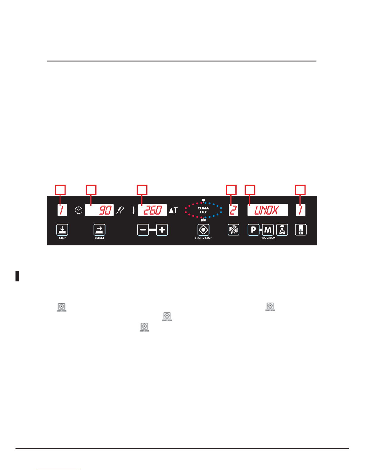
10
Control panel operation
The “ChefTouch” “BakerTouch” control panel is operated by touching the screen-printed keypad with your
finger (do not use any other objects such as forks, knives, etc.). Functions can thus be activated and values set
as desired.
This technology also makes cleaning the control panel quick and easy, while guaranteeing maximum reliability
and durability and avoiding any type of mechanical shifting.
Control panel layout:
1 2 3 4 5 6
Switching the appliance on / off
When the oven is connected to the power supply, the control panel switches on automatically.
After 15 minutes, if none of the buttons have been pressed and if none of the devices connected to the
electronic control panel (ovens, blast chiller, holding cabinet) are in operation, it will enter standby mode: only
the
LED will remain lit. To reactivate the electronic control panel, simply press the
button.
To activate standby mode, press and hold the
button for 6 seconds while the electronic control panel is
on; to reactivate the panel, press the button again.
ChefTouch-BakerTouch digital control panel
Page 11

English
BakerTop
™
ChefTop
™
11
Manual operation
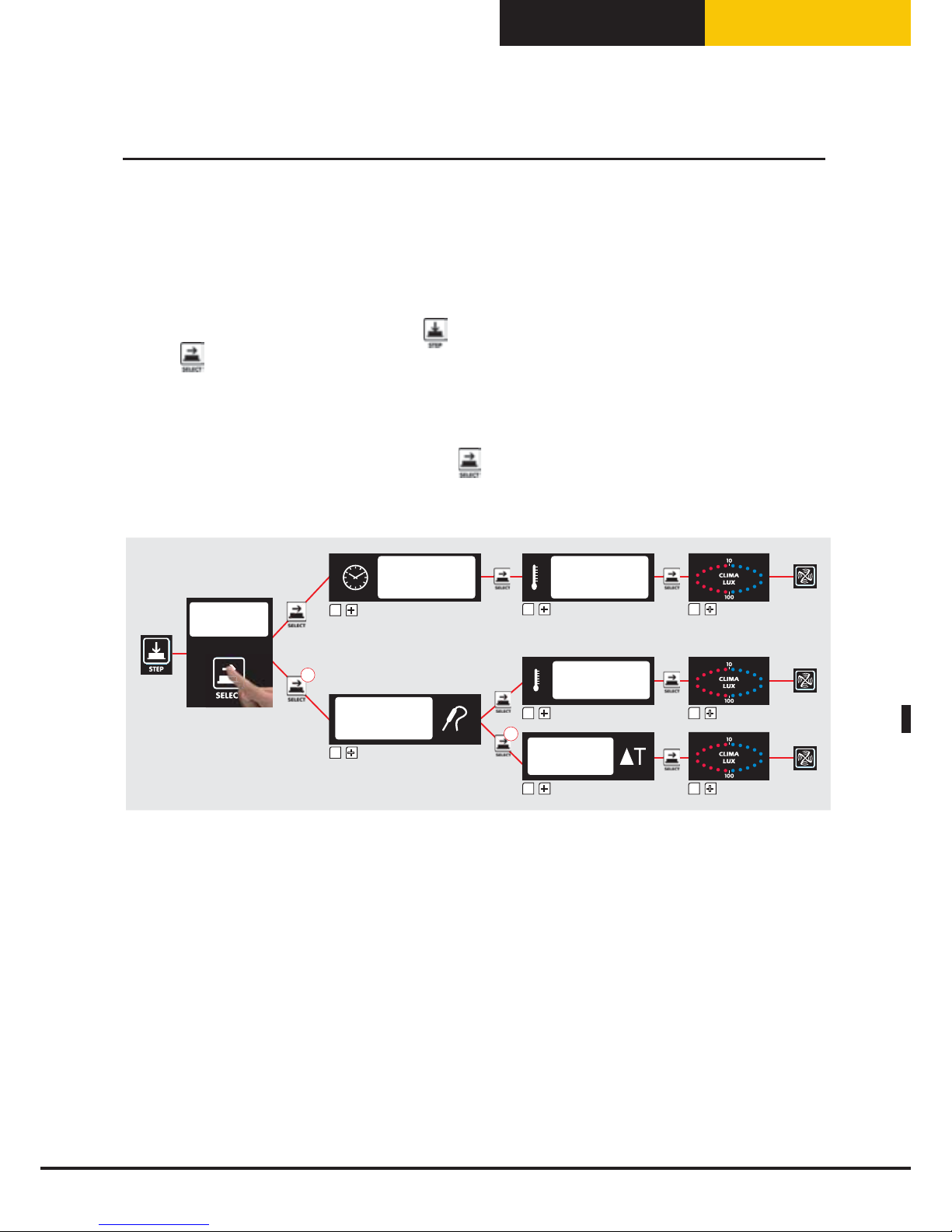
Selecting cooking parameters
The following parameters may be set for each step:
Time or core temperature (these two parameters cancel each other out: if the time is set, the core temperature
parameter will automatically become inoperable, and vice-versa);
Cavity temperature, or alternatively Delta T (Delta T is available only if the core temperature has been set);
CLIMA LUX, if necessary, to set the humidity extraction percentage (DRY.Maxi™) or the steam release
percentage (STEAM.Maxi™);
Use the
button to pass from one parameter to the next; the active parameter is indicated by one of the
five icons lighting up.
It is also possible to select the speed of the airflow inside the oven cavity (3 continuous speeds and 3 semistatic operating modes).
To adjust the airflow speed, press the
button; the active speed level is indicated on display 4.
N.B.
A complete cooking cycle does not necessarily require the implementation of all four steps.
Only the desired steps should be set. This will not compromise oven performance.
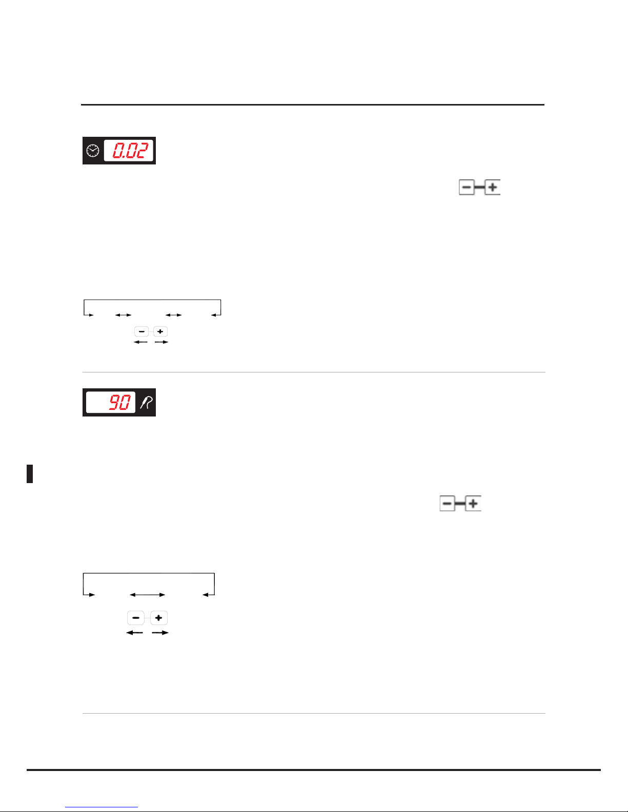
Setting the cooking duration or core temperature
The cooking duration and core temperature parameters control the length of each cooking step.
In general, the more food placed in the oven, the longer the period of time required to complete the cooking
process and vice-versa.
Instead of a cooking duration, it is possible to set a temperature value for the core probe. Once this value is
reached, the next cooking step will begin or the cooking program will end as required.
In this case, the cooking duration is automatically adjusted to suit the amount of food placed inside the oven
cavity.
A shorter duration than is required by the food - or a core temperature which is too low - will result in the
food not being cooked properly.
A longer cooking duration than that required by the food - or a core temperature which is too high - will result
in the food drying out and burning on the surface.
The time and core temperature parameters are mutually exclusive: if a duration is set, the core temperature
parameter will be inoperable, and if the core temperature is set the time parameter will be inoperable.
It will therefore be necessary to set either the time parameter or the core temperature parameter: if neither
parameter is selected, the control panel will not allow any further parameters to be set (cavity temperature,
Delta T, Climate).
Control panel operation
Page 12
English
12
Setting the cooking duration
The time parameter is indicated via display 2, in hours.minutes, and can be set using the buttons.
If cooking step 1 is selected and the text "INF" (INFINITE) appears on display 2, the oven will operate
continuously until it is stopped manually by the user.
When the HOLD ("HLD") function is selected in subsequent cooking steps, the fans only operate when the
heating elements are on.
inF
9h 59'0h 00'
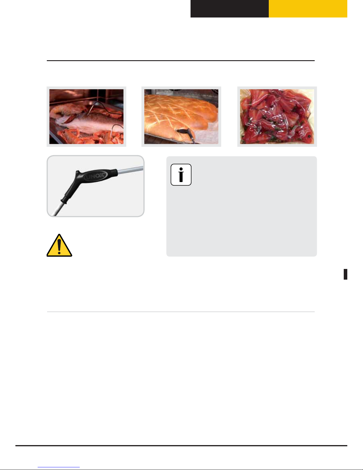
Setting the core temperature
The core probe measures the increase in temperature inside the product during the entire cooking procedure,
and should be inserted into the thickest part of the food, with the very tip at the centre. You must make
sure that this probe is correctly positioned before beginning the cooking cycle: incorrect positioning may
compromise the end result.
The core temperature parameter is indicated via display 2, and can be set using the
buttons.
When the set core temperature is reached, that cooking step is considered complete and the next step begins
(where applicable).
0°C 100°C
The XC249 external core probe kit can be used to connect an extra, smaller core probe which is suitable for
cooking vacuum-packed goods and products which come in smaller pieces.
Setting the parameters
Page 13
English
BakerTop
™
ChefTop
™
13
Setting the cavity temperature or the Delta T value
The exact setting of the temperature inside the cavity ensures the food is cooked properly, both inside and
outside.
A lower temperature than the specified value dries the food out instead of cooking it.
A higher temperature than the specified value burns the surface while the core remains uncooked (sometimes
this is the desired result, especially where meat is concerned).
Cooking with the DELTA-T parameter is only possible during cooking steps which use the core probe to
control the cooking duration. By DELTA-T, we mean the difference between the temperature inside the oven
cavity and the value detected by the core probe inside the product.
The cavity temperature and Delta T parameters are mutually exclusive: if the cavity temperature is set, the
Delta T parameter is inoperable, and if the Delta T is set, the cavity temperature parameter is inoperable.
Setting the parameters
Caution!
Protect your arms and
hands - Risk of injury!
Always position the core probe as instructed.
Risk of damage!
Do not leave the probe hanging out of the
oven cavity.
Risk of damage!
Remove the probe from the food before
taking the pan or the dish out of the oven.
Risk of damage!
Page 14
English
14
Setting the cavity temperature
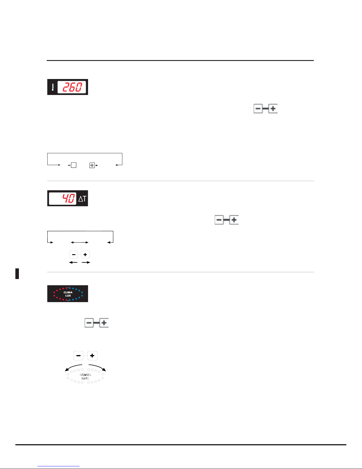
The temperature inside the cavity is indicated via display 3, and can be set using the buttons.
When the text "PAU" appears on display 3, the oven enters pause mode: the fans and heating elements remain
inactive. To postpone oven activation or to apply a pause period (useful for letting certain products rise), set
the pause duration on display 2 and the "PAU" symbol on display 3.
-
+
PAU
0° C
260° C
Setting the Delta T value
The Delta T value is indicated via display 3, and can be set using the buttons.
0°C 100°C
Setting the climate
The oven cavity internal climate setting (STEAM.Maxi / DRY.Maxi) is indicated by the CLIMA LUX ellipse and
is set using the
buttons.
The 10 blue LEDs indicate the percentage of humidity or steam inside the oven cavity (STEAM Maxi);
The 10 red LEDs indicate the drying percentage (DRY Maxi).
STEAM
Maxi
DRY
Maxi
N.B.
The two systems cannot be used simultaneously. Setting the CLIMA LUX parameter is optional. If this
parameter is not set the oven operates in "CONVECTION" mode.
Setting the parameters
Page 15
English
BakerTop
™
ChefTop
™
15
Steam / Humidity release inside the oven cavity: STEAM.Maxi™
Your oven is equipped with exclusive STEAM.Maxi technology for the generation of steam inside the oven cavity.
This innovative technology allows you to carry out any kind of steam cooking, starting from a temperature of
48°C, while guaranteeing maximum accuracy in terms of steam production temperature control.
STEAM.Maxi™ introduces adjustable amounts of steam in conjunction with various temperatures, allowing
different types of cooking to take place:
• Steaming (only steam);
• Mixed convection-steam cooking (air+steam).
Through the ADAPTIVE.Clima technology, BakerTop™ and ChefTop™ ovens constantly monitor all cooking
parameters, not only in terms of temperature, but also the current humidity level inside the cavity. This
ensures the most suitable cooking program is always applied, to help each user achieve perfect results every
time, regardless of the number of trays placed inside.
The ADAPTIVE.Clima function will release the amount of steam required to create the humidity percentage
set by the user.
Caution!
During the cooking process, the product inside the oven releases a certain amount of steam: it may happen,
therefore, that the appliance does not produce any steam, if the moisture released by the food is sufficient to
achieve the value requested by the user. In this case the lack of steam production is not due to an appliance
malfunction, but is the result of oven monitoring and control procedures taking place correctly.
To set the desired humidity level inside the oven cavity, proceed as follows:
• Press the
button repeatedly until the CLIMA LUX display
flashes;
• Use the
button to set the desired steam release percentage (STEAM.Maxi™).
The 10 blue LEDs indicate the humidity percentage level inside the cavity requested by the user, which can
vary from 10% to 90% for each step in the cooking cycle. If 100% is selected - and for temperatures below
130°C - the oven will automatically activate its steam only mode.
Setting the parameters
Page 16
English
16
Extracting humidity/steam from the oven cavity: DRY.Maxi™
The patented DRY.Maxi™ technology makes it possible to quickly extract all the humidity from the oven
cavity, whether it was released by the products in the oven or generated by the STEAM.Maxi™ system in
a previous cooking step.
The DRY.Maxi™ technology means that ChefTop™ and BakerTop™ ovens guarantee enhanced flavours,
whether cooking restaurant dishes or baking pastry and bread products.
To set the desired humidity extraction level inside the oven cavity, proceed as follows:
• Press the button repeatedly until the CLIMA LUX display
y,
p
flashes;
• Use the button to set the desired humidity extraction percentage (DRY.Maxi™).
The 10 red LEDs indicate the variable humidity percentage (between 10% and 100%) which needs to be
extracted from the oven cavity.
Setting the airflow speed
The option of setting 3 airflow speeds inside the oven cavity, in addition to the 3 semi-static operating modes,
means it is possible to cook any product, from delicate and light foods to those which require a great deal of
heat.
The button can be used to set the motor revolution speed and operating mode. There are 3 continuous
revolution speeds and 3 semi-static operating modes.
The semi-static mode only activates the motors when the heating elements are on, which accurately reproduces
the effects of a traditional static oven. The fan is activated for a few moments, in order to evenly distribute the
heat produced by the heating elements and to ensure the temperature remains uniform throughout the oven
cavity. The speed selected previously is indicated on display 4 and can be selected using the
button, in the
following sequence:
• 1: indicates that the revolution speed is set to minimum
• 2: indicates that the revolution speed is between the minimum and maximum settings
• 3: indicates that the revolution speed is set to maximum
• 1P: indicates semi-static operation, with the revolution speed set to minimum
• 2P: indicates semi-static operation, with the revolution speed set to the medium value
• 3P: indicates semi-static operation, with the revolution speed set to maximum
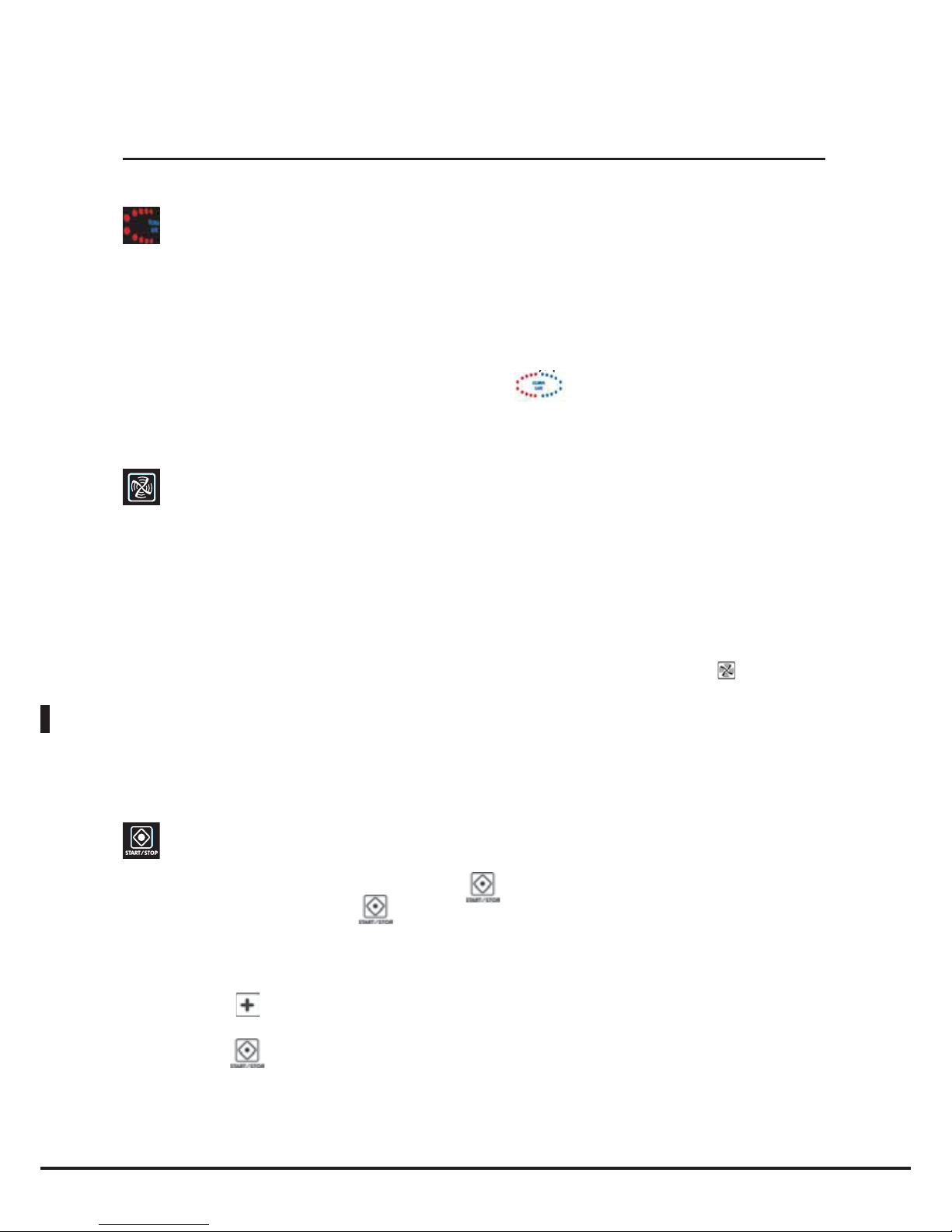
Starting / stopping the cooking process
Once you have set all the cooking parameters, press
to start the cooking cycle.
To stop the cooking cycle, press the
button again.
When the cooking cycle has finished, both in manual and programmed mode, the oven emits an audible alarm
for 15 seconds and the display flashes for 45 seconds.
During this 45-second period, the “START / STOP” LED remains on.
If you press the
button during this period, the set cooking time will be increased and the oven will
automatically start again (using the most recent cooking parameters).
If you press the
button the “START / STOP” LED will switch off and all operating parameters will be
reset.
If none of the buttons are pressed within 45 seconds, the “START / STOP” LED will switch off and all operating
parameters will be reset.
Setting the parameters
Page 17
English
BakerTop
™
ChefTop
™
17
Starting / stopping the cooking process
Selecting the cooking steps
Each cooking process consists of up to 9 steps.
To move from one step to the next, press the
button; the active step will be indicated on display 1.
Use the
button to pass from one parameter to the next; the active parameter is indicated by one of the
five icons lighting up.
Caution: the parameter displayed by pressing the
button may vary, depending on the selections made
when using the control panel to set the cooking duration (see diagam below):
-
+
-
x2
x2
-
+
-
-
+
-
-
+
-
-
+
-
-
+
-
-
+
-
-
+
-
It is therefore not possible to cook with the DELTA-T function if the cooking step duration has been set using
the COOKING DURATION function.
Selecting the cooking steps
Page 18
English
18
Cooking with a set duration and cavity temperature
First step:
Press the
button until the timer display begins to flash ;
Use the
-
+
-
buttons to set the duration as desired.
-
+
1° STEP
INF
INF
9h 59’
-
+
2° 3° 4°... STEP
HLD
HLD
0h 00’
9h 59’
0h 00’
N.B.
During cooking step 1, an indefinite duration "INF" may be set; in this case the oven will maintain the temperature
and humidity parameters indefinitely and will have to be stopped manually by the user. During cooking steps
2/3/4, the "HLD" function may be selected in order to maintain a constant cavity temperature of 70°C until the
oven is switched off manually; this keeps the food inside the oven hot and ready to be served.
Second step:
Press the
button again, until the temperature display begins to flash;
Use the
-
+
-
buttons to set the desired cavity temperature.
-
+
PAU
0° C
260° C
N.B.
The pause function, "PAU", may be selected at any time. During this time, the oven will remain in Standby
mode, with the fans, heating elements and burner switched off. This is a useful function for many types of
cooking, particularly if you wish to limit "Thermal pressure" on the product.
Third step:
CLIMA LUX, if necessary, with a humidity extraction percentage (DRY.Maxi™) or steam release percentage
(STEAM.Maxi™):
• Press the button again, until the CLIMA LUX display
begins to flash;
• Use the
+
button to set the desired steam
release percentage (STEAM.Maxi™)
;
•
Use the - button to set the desired humidity extraction percentage (DRY.Maxi™);
• Leave the setting as Ø for convection-only cooking, without releasing or extracting steam.
Fourth step:
To change the airflow speed, press the
button;
the current speed level is indicated on display 4.
Setting the cooking programs
Page 19
English
BakerTop
™
ChefTop
™
19
Cooking with the core probe at a set oven cavity temperature
First step:
Press the
button until the core temperature symbol begins to flash;
Use the
-
+
-
buttons to set the desired core temperature.
-
+
0° C
120° C
N.B.
By setting the core temperature, the cooking duration is set automatically.
As soon as the set core temperature is reached, the oven moves on to the following step (if selected) or the
cooking cycle ends.
Second step:
Press the
button again, until the temperature display begins to flash;
Use the
-
+
-
buttons to set the desired core temperature.
-
+
PAU
0° C
260° C
N.B.
The pause function, "PAU", may be selected at any time. During this time, the oven will remain in Standby
mode, with the fans, heating elements and burner switched off. This is a useful function for many types of
cooking, particularly if you wish to limit "Thermal pressure" on the product.
Third step:
CLIMA LUX, if necessary, with a humidity extraction percentage (DRY.Maxi™) or steam release percentage
(STEAM.Maxi™):
• Press the ) button again, until the CLIMA LUX display
begins to flash;
• Use the
+
button to set the desired steam
release
percentage (STEAM.Maxi™);
•
Use the - button to set the desired humidity extraction percentage (DRY.Maxi™);
• Leave the setting as Ø for convection-only cooking, without releasing or extracting steam.
Fourth step:
To change the airflow speed, press the
button;
the current speed level is indicated on display 4.
Setting the cooking programs
Page 20
English
20
Cooking with the core probe at a set Delta T
First step:
Press the
button until the core temperature symbol
begins to flash;
Use the
-
+
-
buttons to set the desired core temperature.
-
+
0° C
120° C
N.B.
By setting the core temperature, the cooking duration is set automatically.
As soon as the set core temperature is reached, the oven moves on to the following step (if selected) or the
cooking cycle ends.
Second step:
Press the
button again, until the Delta T display begins to flash;
Use the
-
+
-
buttons to set the desired Delta T.
-
0° C
260° C
+
N.B.
7KH RYHQ Z LOO QHYHU XQGHUDQ\ FLUFXP VWDQFHV RSHUDWH DW WHP SHUDWXUHV DERYH
Third step:
CLIMA LUX, if necessary, with a humidity extraction percentage (DRY.Maxi™) or steam release percentage
(STEAM.Maxi™):
• Press the
button again, until the CLIMA LUX display
begins to flash;
• Use the
+
button to set the desired steam release percentage (STEAM.Maxi™);
• Use the - button to set the desired humidity extraction percentage (DRY.Maxi™);
• Leave the setting as Ø for convection-only cooking, without releasing or extracting steam.
Fourth step:
To change the airflow speed, press the
button;
the current speed level is indicated on display 4.
Setting the cooking programs
Page 21
English
BakerTop
™
ChefTop
™
21
Operation using programs
The ChefTouch/BakerTouch electronic control panel allows the user to save up to 99 cooking
programs, each assigned with a name up to 25 letters long.
Access the programming menu by pressing the
button;
Select the location in which you wish to save the program (from P01 to P99) using the
-
+
-
buttons indicated
on display 5; press
and use the
-
+
-
buttons to select the first letter of the name as desired;
Press
again and use the
-
+
-
buttons to select the second letter;
Repeat this procedure for subsequent letters;
Finally, press the
button to select the oven preheating temperature. The text "PRE" will appear;
Use the
button to select either an absolute preheating temperature
or a temperature
difference
between the preheating value and the value for the first cooking step of program;
Use
-
+
-
to set the desired value, expressed in degrees;
Press the
button to move to the next step and set the desired operating parameters (Duration, Core
Temperature, Cavity Temperature, Delta T, Climate) for the step;
Press the
button and set the parameter governing airflow speed inside the oven cavity;
Press and hold the
button for 5 seconds to store the program in the memory (after 5 seconds a confirmation
beep will sound).
Using saved programs:
Access the programming menu by pressing the
button;
Press the
-
+
-
buttons until the number correpsonding to the desired program appears on display 5;
Press the
button to start the selected program;
Press the
button again to stop the program.
N.B.
When a saved cooking program is started, the oven preheats automatically to the setted preheating temperature.
When a cooking program is started, the oven begins the set preheating step. During this step, all the LEDs
and displays remain off except the "START / STOP" LED, display 2 (which shows the text "PRE") and display 4
(which indicates the program being used). When the desired temperature has been reached and is maintained,
the oven beeps and the data corresponding to the first cooking step appears on the display. After the door has
been opened, the food placed inside and the door closed again, the cooking program begins automatically.
User programming procedures
SHORT WASHING
LH2O WASHING
COOL
SEMI-AUTO WASHING
RESTART
LAST P
P01
P02
...
P99
MED WASHING
LONG WASHING
PUMP LOADING
P
- +
Page 22
English
22
LASTP function
This can be used to quickly select the most recently used cooking cycle, whether it was activated manually or
in programmed mode.
When the cooking cycle has finished, press the
button. The text "LASTP" will appear on display 5;
Press the
button to start the most recently used cooking cycle again.
Automatic washing programs
The Rotor.KLEAN™ washing system, code XC405, offers automatic washing of the oven cavity. Automatic
washing programs can only be used if the appliance features this option. The Rotor.KLEAN™ washing system
may also be installed after the appliance has been commissioned.
3 washing programs (SHORT WASHING, MED WASHING and LONG WASHING) are stored in the control
P.C.B. memory, as well as a pre-loading program for the detergent and rinse aid pipes (PUMP LOADING).
There are another two semi-automatic programs: "LH2O", which can be used to rinse and dry the oven cavity
at a temperature of 120°C, without the use of chemicals and “SEMI-AUTOMATIC WASHING” which can
wash the oven cavity using a pre setted temperature and chemicals products manually.
Access the programming menu by pressing the
u
u
button;
Press the
-
+
-
buttons repeatedly until the LH2O, SHORT WASHING, MED WASHING, LONG WASHING
or PUMP LOADING washing programs appear on display 5;
Press the
button to start the selected program;
N.B.
The first time the washing system is used, it is advisable to run the PUMP LOADING program to remove any
air inside the detergent and rinse aid pipes, so that the quality of the wash is not compromised.
These programs are only used if the Rotor.KLEAN™ washing system (XC405) is installed.
Caution!
Never open the oven cavity door while a cleaning cycle is in progress - chemical cleaning substances and hot air may escape
- risk of corrosion and burns! When the cleaning cycle implemented by the Rotor.KLEAN™ system is complete, make sure
that there is no detergent residue remaining in the oven cavity (including the area behind the air channel panelling). Remove
any residue and rinse the entire oven cavity thoroughly (including the area behind theair channel panelling) using a hand-held
shower head - risk of corrosion!
Standard functions
Caution!
We recommend the oven cavity is cleaned on a daily basis, in order to maintain acceptable hygiene standards and
to prevent the stainless steel inside the cavity from being ruined. We would therefore recommend the use of the
Rotor.KLEAN™ washing system, code XC405, which offers automatic washing of the oven cavity. Caution!
If the appliance is not cleaned or not cleaned thoroughly enough, grease or remnants of food which have accumulated
inside the oven cavity may start to burn - fire hazard!
To prevent corrosion from occurring inside the oven cavity, the appliance should be cleaned every day, even if it is only
used for steam cooking purposes.
Only use detergents which have been recommeded by the appliance manufacturer. Detergents from other manufacturers
may damage the appliance and therefore invalidate the guarantee.
Page 23

English
BakerTop
™
ChefTop
™
"COOL" program for oven cavity cooling
The “COOL” program is used for oven cavity cooling; it allows the fans inside the cavity to rotate whilst the
heating elements remain off. The program can also be started with the door open, to accelerate the cavity
cooling process. During this program, the temperature inside the oven cavity is displayed.
• Access the programming menu by pressing the
button;
• Press the
-
+
-
buttons until the LCOOL program appears on display 5;
• Press the
button to start the selected program.
23
Standard functions
Page 24

English
24
ADAPTIVE.Clima function
Through the ADAPTIVE.Clima technology, ChefTop™ and BakerTop™ ovens constantly monitor all cooking
parameters, not only in terms of temperature, but also the current humidity level inside the cavity. This
ensures the most suitable cooking program is always applied, to help each user achieve perfect results every
time, regardless of the number of trays placed inside.
The amount of steam released inside the oven cavity varies in accordance with the amount of food placed
inside the appliance, even when the same program is used. As a general rule, the greater the amount of food
placed inside the oven, the less steam will be produced by the oven.
The ADAPTIVE.Clima technology can also be used to store the most recently used cooking process in the
memory of the appliance. For this use we recommend to use the MULTI.Point core probe in order to prevent
positioning mistakes.
The constant monitoring of all cooking parameters allows ChefTop™ and BakerTop™ ovens to acquire
information regarding changes in the temperature and humidity level during the entire cooking process,
while gathering information on the effects of any manual interventions from the user (opening the door, for
example).
Once the desired result has been achieved, the ADAPTIVE.Clima technology also allows the user to store
the implemented process in the memory of the appliance so that it can be repeated as often as necessary in
the knowledge that the results will always be the same, without any user intervention or supervision being
required.
The oven will automatically reproduce the effects of the user's actions during the "pilot" process (the one you
wish to repeat): if, for example, the door was opened in the third minute, causing the temperature to drop by
20°C and the humidity inside the cavity to disperse, the oven will also simulate these effects in the subsequent
cooking processes.
Caution: to store an ADAPTIVE.Clima program in the memory correctly, the core probe must have been
inserted correctly during the “pilot” cooking process, even if the program set on the control panel did not
require its application.
To store the cooking process you have just completed in the memory of the appliance using the ADAPTIVE.
Clima technology, proceed as follows:
• At the end of the cooking process, press the
button;
• Use the
+
button to select the program memory slot in which you would like to store the “pilot” cooking
process. For example ACM01, ACM02, …ACM20
• Press
and use the
-
+
-
buttons to select the first letter of the name you wish to assign to the
program;
• Press
again and use the
-
+
-
buttons to select the second letter;
• Repeat this procedure for subsequent letters;
• Press and hold the
button for 5 seconds to store the program in the memory (after 5 seconds a
confirmation beep will sound).
Caution: it is not possible to modify any of the parameters for a stored ADAPTIVE.Clima program.
Standard functions
Page 25
English
BakerTop
™
ChefTop
™
25
ChefUnox - BakerUnox automatic cooking processes
The ChefTouch - BakerTouch digital control panel has a set of suggested automatic cooking settings devised by
ChefUnox - BakerUnox stored in its memory.
Simply select the desired type of cooking to automatically prepare an endless range of foods.
Every type of automatic cooking program offers the option of customising certain parameters, in order to
achieve the optimal level of browning and cooking in line with your own requirements.
• Press the
button;
• Use the
-
button to select the desired program;
• Press the
button to start the program;
• Press the
button again to stop the program.
N.B.
Before starting the program, you may change the value of a parameter which can be used to adjust the cooking
level as desired. The oven will adjust its cooking performance accordingly, in order to gurantee a perfect
result.
• Press the
button until the parameter you want to modify flashes;
• Use the
-
+
-
buttons to set the new value as desired.
If you want to make this change permanent:
• Press and hold the
button for 5 seconds (you will then hear a beep to indicate the program has been
saved).
DESCRIPTION
ADJUSTABLE
PARAMETER
WHEN TO INCREASE WHEN TO DECREASE
ROASTING Roasting meats Core probe 54°C Increase the cooking level Decrease the cooking level
CRISPY ROAST Roasting meats with a crust Core probe 54°C Increase the cooking level Decrease the cooking level
NIGHT ROAST
Roasting meats overnight
Core probe 54°C Increase the cooking level Decrease the cooking level
BRAISE Braising and stewing meats Cooking time 1 h Increase the cooking level Decrease the cooking level
GRILL Grilling vegetables and meats
9 Timers can be set, use
FAKIRO Grill
--
MULTI TIME
Simultaneous cooking of
several products for various
periods of time
Set temperature and
CLIMALUX, press Start and
use the step button to set the
9 timers
--
CHICKEN
Cooking chicken, birds,
poultry, game
Time 5 min Increase external browning Decrease external browning
ROAST POTATO Roast potatoes Time 5 min Increase external browning Decrease external browning
BAKING
Cooking frozen baked goods
Time 5 min Increase the cooking level Decrease the cooking level
+3 REGEN Regeneration from 3°C Core probe 65°C
Increase the temperature of
the dish for service
Decrease the temperature
of the dish for service
Pre-set cooking procedures
Page 26
English
26
MAXI.Link technology:
controlling several appliances using the same control panel
The ChefTouch – BakerTouch digital control panel allows the user to control a variety of UNOX ChefTop™
- BakerTop™ appliances connected to the oven. The MAXI.Link technology also allows the user to control
several ovens with a single digital control panel. The oven used to control all the other appliances becomes
the MASTER oven. The ovens controlled by the MASTER oven become SLAVE ovens, and their digital control
panels remain inactive. The MASTER and SLAVE digital control panels are interchangeable in the event of an
emergency.
The appliance to be controlled is selected using the
button; this selection is indicated by display 6.
Number / appliance correspondence table
ChefTop™
Appliance number Appliance code Device
1 ChefTop™ master oven
2 ChefTop™ slave oven 1
3 ChefTop™ slave oven 2
4 ChefTop™ slave oven 3
5 XK305 Blast chiller
6 XVL575 - XVL375 Holding cabinet / Slow cooking oven
7 XC235 Reverse osmosis system
9 XC236 Kit OVEX.Net 2.0
BakerTop™
Appliance number Appliance code Device
1 Forno BakerTop™ master
2 Forno BakerTop™ slave 1
3 Forno BakerTop™ slave 2
4 Forno BakerTop™ slave 3
6 XL405 Prover
7 XC235 Reverse osmosis system
9 XC236 Kit OVEX.Net 2.0
MAXI.Link technology
Page 27

English
BakerTop
™
ChefTop
™
27
Chef’s recommendations for even cooking
Preheating
It is always better to preheat the oven to a temperature at least 30-50°C higher than is required for cooking,
in order to reduce the effects of heat lost when opening the door.
The oven may be preheated to 300°C.
Do not heat the oven to a temperature over 260°C for periods of longer than 10 minutes.
Tray types
To achieve perfect cooking quality and even browning of the product, it is better not to use recipients which
are too tall and prevent correct air circulation.
Tray spacing
For even cooking it is important to make sure there is at least 3 cm of free space between the product once
it has risen and the tray above.
Quantity of food
To achieve the best results, it is important not to overload the oven; you should also make sure, when baking
bread and pastry, the food on the trays is facing the right direction in relation to the airflow.
Core probe positioning
For correct operation, it is essential that the core probe is inserted from top to bottom, at the thickest point
of the food, until the tip reaches the centre.
When cooking thinner foods, the core probe should be inserted horizontally to the support surface.
Be careful when opening the door!!!
Heat and steam could cause burns.
Cooking principles
Page 28
English
The digital control panel used in ChefTop™ - BakerTop™ ovens is designed to offer a straightforward interface
between the oven and the outside world, by means of existing communication systems and those to be used in the
future: USB, Bluetooth, serial port etc.
The USB XC236 interface kit can be used to carry out the following functions:
• entering cooking programs
• modifying operating parameters (e.g. probe calibration)
• diagnosing malfunctions
• storing oven cavity or blast chiller temperature changes in the memory of the appliance (data required for the HACCP system)
Further information is supplied with the kit.
Warning messages:
When a malfunction is detected which allows the appliance to continue operating, abeit in a limited manner, a
WARNING message is displayed.
The device continues to run and the WARNING message remains on the display until the button is pressed.
Warning messages oven:
Display message Description Effect Problem solution
WF01
An error has been detected in the data recorded by
cavity probe 1
The oven contines to operate, using the data
from cavity probe 2 only
Contact the Customer Assistance Service
WF02
An error has been detected in the data recorded by
cavity probe 2
The oven contines to operate, using the data
from cavity probe 1 only
Contact the Customer Assistance Service
WF03
An error has been detected in the data recorded by
the core probe
It is not possible to set steps or activate
programs which use the core probe; if a step
which uses the core probe is in progress, the
following step will begin
Contact the Customer Assistance Service
WF04
Non correct fan rotation speed Turn off the motor breaking system
Contact the Customer Assistance Service
WF05
An error has been detected in the cooling system for
the electronic components
The cooling fan for the electronic components
may not work
Contact the Customer Assistance Service
WF06
The temperature of the oven power P.C.B. is too
high
There is a risk of permanent
damage to the power P.C.B.
Make sure the positioning standards
specified in the installation manual have
been observed. Contact the Customer
Assistance Service
WF08
Gas board detected while the oven is set as electric
The oven keeps on working but is controlled
as electric
Contact the Customer Assistance Service
WF09
Error on the motor breaking system
The oven keeps on operating but the motor
breaking system is not working
Contact the Customer Assistance Service
WF10
Non basic power board setting error
The oven keeps on working (with some
limitations due to the setting involved on the
error)
Contact the Customer Assistance Service
WF11
Not correct temperature on the gas board The oven keeps on operating
Contact the Customer Assistance Service
WF12
Too high temperature on the external thermocouples
board
The oven keeps on operating
Contact the Customer Assistance Service
WF13
The external sous-vide probe takes non correct data
The oven keeps on working but it is not possible
to use external sous-vide probe
Contact the Customer Assistance Service
WF14
Error on the data taken by the Multi.point core probe
(totally not working)
The oven keeps on working but it is not possible
to use cooking programs with the core probe
Contact the Customer Assistance Service
WF15
Error on the board-thermocouples communication
system
The oven keeps on working but it is not possible
to use external sous-vide probe
Contact the Customer Assistance Service
WF17
Error on the data taken by the Multi.point core probe
(partially not working)
The oven keeps on working but the core
temperature may be not precisely taken
Contact the Customer Assistance Service
28
Oven-user communication
Page 29
English
BakerTop
™
ChefTop
™
Warning messages (attention) panel control board:
Display message Description Effect Problem solution
WD10
Non basic control board
setting error
The oven keeps on working (with
some limitations due to the setting
involved on the error)
Contact the Customer
Assistance Service
Alarm messages:
When a condition arises which prevents the appliance from operating at all, an ALARM signal is displayed and
the appliance must be switched to its STOP status.
The device stops operating and the ALARM! message appears on the oven display until the problem is resolved.
If the device is operating when the ALARM status occurs, it will shut down and the alert corresponding to the
detected problem will be displayed.
To resolve a problem of this type, contact an Authorised Assistance Centre.
Once the problem has been resolved, the appliance can be reactivated by pressing the "START/STOP"
button.
If any other devices/accessories are connected to the oven, these will continue to operate normally unless the
alarm corresponds to a specific device that prevents its continued operation.
Alarm messages oven:
Display message Description Effect Problem solution
AF01
The motors have overheated Oven shutdown Contact the Customer Assistance Service
AF02
The safety thermostat has
overheated
Oven shutdown Contact the Customer Assistance Service
AF03
An error has been detected
in the data recorded by both
cavity probes
Oven shutdown Contact the Customer Assistance Service
AF04
Communication between the
control P.C.B. and the power
P.C.B. has been cut off
Oven shutdown Contact the Customer Assistance Service
AF05
Communication between the gas
P.C.B and the power P.C.B. has
been cut off
Oven shutdown Contact the Customer Assistance Service
AF06
Gas oven exhaust fumes reach too
high temperature
Oven shutdown Contact the Customer Assistance Service
AF10
Power card settings error Oven shutdown Contact the Customer Assistance Service
GAS
There is no flame in the
burner
The burner is deactivated. Ignition
may be attempted again by ressing
the “START/STOP” button
In case it is not possible to re-start the oven,
immediately close the gas cock
N.B.
Every time the oven is started electrically, and every time the control P.C.B. exits STANDBY mode, the control
P.C.B. is scanned for ALARM / WARNING conditions (which appear on the display, if present).
Oven-user communication
29
Page 30
English
Alarm messages panel control board:
Display message Description Effect Problem solution
AD01
An error has been detected in the control
board memory
Oven shutdown Contact the Customer Assistance Service
AD02
An error has been detected on the keyboard
Oven shutdown Contact the Customer Assistance Service
AD03
An error has been detected in the display
Oven shutdown Contact the Customer Assistance Service
AD04
Communication has been cut off
Oven shutdown Contact the Customer Assistance Service
AD10
Basic control board setting error
Oven shutdown Contact the Customer Assistance Service
Maintenance in the event of a malfunction:
In the event of a malfunction, deactivate the appliance:
Disconnect the appliance from the electricity supply.
For gas appliances
Cut off the gas supply immediately.
Contact a Technical Assistance Centre with specially trained personnel.
Before calling the Customer Assistance Service:
Malfunction Possible cause Solution
The oven is completely switched off No mains power
Make sure the appliance is connected to
the electricity mains
No steam is produced inside the oven
cavity
Water inlet closed Open water inlet
Appliance plumbed into the water mains
or the tank incorrectly
Make sure the appliance is plumbed into
the water mains or the tank correctly
No water in the tank (if water is taken
from the tank)
Fill the tank with water
Water inlet filter blocked Clean the filter
After the duration or core
temperature has been set and the
START / STOP button pressed, the
oven does not start
Door open or not shut properly Make sure the door is shut
Water escapes from the seal while
the door is shut
Seal dirty Clean the seal using a damp cloth
Seal damaged
Contact a specialised technician to
request the necessary repair work
The handle mechanism is loose
Contact a specialised technician to
request the necessary repair work
Oven-user communication
30
Page 31
English
BakerTop
™
ChefTop
™
Safety regulations
All installation, assembly, assistance and maintenance procedures must be performed by qualified personnel in
accordance with current regulations.
These technicians must, nevertheless, be aware of and apply the regulations relating to the safety of repaired
products and safety in the workplace.
Appliance installation by qualified personnel not authorised by UNOX will invalidate the guarantee.
In light of the above information, UNOX accepts no responsibility for any situation resulting from work carried
out in an unprofessional manner, or from the incorrect intepretation or application of regulations or the
instructions supplied in this manual.
Caution!
Incorrect installation, assistance, maintenance or cleaning procedures, or any modifications made to the
appliance, may damage property or result in injury or even fatal accidents.
Read the installation instructions carefully before installing the appliance.
This appliance may only be used to cook food in industrial kitchens.
Any other application does not conform to the specified use and is therefore considered hazardous.
Gas appliances only
If the appliance is installed below a cooker hood, the hood should be switched on while the operation.
In case the appliance is connected to a chimney, the exhaust pipe has to be clean and free from obstructions
following the current safety rules – risk of fire! (for further information, please contact your installer).
Do not place any objects on top of the exhaust gas hose connected to the appliance - Fire hazard!
The area underneath the appliance should not be blocked or obstructed by any objects - Fire hazard!
The appliance may only be operated in a draught-free environment - Fire hazard!
If you smell gas:
Cut off the gas supply immediately;
Do not touch any of the electrical switches;
Make sure the room is well ventilated;
Avoid the creation of naked flames and sparks;
Use a telephone outside the building and inform your gas supplier immediately.
------
Read the manual carefully before installing and commissioning the appliance.
Make sure the appliance has not been damaged during the transportation process.
If you suspect any damage may have occurred during transportation, inform your local authorised dealer or
the shipping agent.
31
INSTRUCTIONS FOR THE INSTALLER
Page 32

English
Make sure the unit will fit through all doors, corridors or other passageways required to reach the installation site.
The table lists the measurements of the models, with and without packaging:
UNIT/MODEL No packaging
LxDxH mm
With packaging
LxDxH mm
UNIT/MODEL No packaging
LxDxH mm
With packaging
LxDxH mm
ChefTop™ electric ChefTop™ gas
XVC 055 574x737x498 740x800x640 - - -
XVC 105/ 105P 750x782x498 880x880x640 - - -
XVC 205 574x758x632 740x800x780 - - -
XVC 305/ 305P 750x792x625 880x880x780 XVC 315G 750x796x840 870x870x1000
XVC 505/ 505P 750x792x813 880x880x970 XVC 515G 750x796x1028 870x870x1200
XVC 705/ 705P 750x792x960 880x880x1120 XVC 715G 750x796x1175 870x870x1400
XVC 1005P/ 905P 866x972x1866 980x1140x2000 XVC 1015G/ 915G 866x970x2072 980x1140x2250
XVC 1205 860x1160x888 990x990x1300 XVC 1215G 860x1160x1028 -
XVC 2005 860x1160x1208 980x1300x1310 XVC 2015G 860x1160x1348 -
XVC 4005P/ 3205P 869x1206x1857 985x130x2000 XVC 4015G/ 3215G 869x1206x2072 -
BakerTop™ electric BakerTop™ gas
XBC 405 860x900x624 980x1060x772 - - -
XBC 605 860x900x820 980x1060x960 XBC 615G 860x900x1028 950x1030x1180
XBC 805 860x900x1140 980x1060x1280 XBC 815G 860x900x1348 980x1060x1470
XBC 1005/ 905 866x972x1866 980x1140x2000 XBC 1015G/ 915G 866x970x2072 980x1140x2250
The appliance should only be transported using pallets supplied by UNOX.
Caution!
Make sure that the appliance is not in danger of tipping over during transportation.
Take the weight of the appliance into account. Use suitable supports.
Wear protective shoes during the installation process.
32
Instructions for appliance transportation
Page 33

English
BakerTop
™
ChefTop
™
Oven installation is divided into 5 stages:
1) Preliminary and positioning procedures
2) Electrical connection / Gas connection
3) Plumbing: water supply
4) Plumbing: water drainage
5) Smoke exhaust outlet
2
3
5
1
4
Preliminary and positioning procedures
Installation site
Before positioning the appliance, check the measurements and the exact position of the electrical, plumbing
and smoke exhaust connections, in accordance with the figures provided in the enclosed "Technical Data"
booklet.
Caution!
Do not install the appliance near flammable materials.
If the appliance is positioned near walls, partitions, kitchen cabinets, decorative trim, etc., these items must be
made from non-flammable material.
If this is not the case, they must be coated with a non-flammable heat insulating material, and all fire prevention
regulations must be strictly observed.
33
Appliance installation
1. Positioning
2. Electrical connection
3. Water supply
4. Water drainage
5. Smoke exhaust outlet
Page 34

English
Removing the protective film
Carefully remove the protective film from the outer surfaces of the appliance,
so that no glue residue is left behind. Any remaining residue can be removed
using a suitable solvent product.
Removing the protective silicone from the tip of the core probe
Fitting the fixed appliance feet
The feet supplied in the bag inside the packaging ensure sufficient airflow for
the cooling of electronic components and the outer surfaces of the oven. It is
therefore essential that they are fitted correctly. Install the feet at the points
indicated in the illustration.
Caution! Do not use the oven without feet; this could cause the electronic
components to overheat, damaging them beyond repair.
Drip drawer
The drip drawer fixed to the back panel of the oven collects any liquids deposited on the inside of the oven
door, thereby preventing them from dripping onto the floor when the door is opened.
Remove the drip drawer from the rear of the oven using a screwdriver, slide the runners (supplied in the bag
inside the oven) into position and insert the drawer as illustrated in the figure.
34
Appliance installation
Page 35

English
BakerTop
™
ChefTop
™
Warning
Position the appliance so that the back panel is easily accessible when performing electrical connection and
carrying out maintenance work. The appliance is not suitable for recessed installation, or for use as part of a
series of appliances. A minimum gap of 50 mm must be left around the entire perimeter of the appliance.
If any fryers or other potential sources of hot liquid spills are used in the kitchen, they should be placed at least
45 cm away from the sides and 70 cm away from the back of the oven.
450 mm
700 mm
50 mm
50 mm
For safety reasons, tabletop appliances must only be placed on supporting structures or cabinets from the
appliance manufacturer. The maximum operating height for the top shelf level is 1600 mm.
1600 mm
The safety labels «max. height of thelast
shelf for containers holding liquids» can be
found in the starter kit.
After installing theappliance, apply thelabel
at aheight of 1600 mm.
(see example)
Tabletop ovens require the use of special stands, leavening devices or tray racks, or should be placed on top
of a stainless steel table.
Do not install ovens directly on the floor.
35
Positioning
Page 36
English
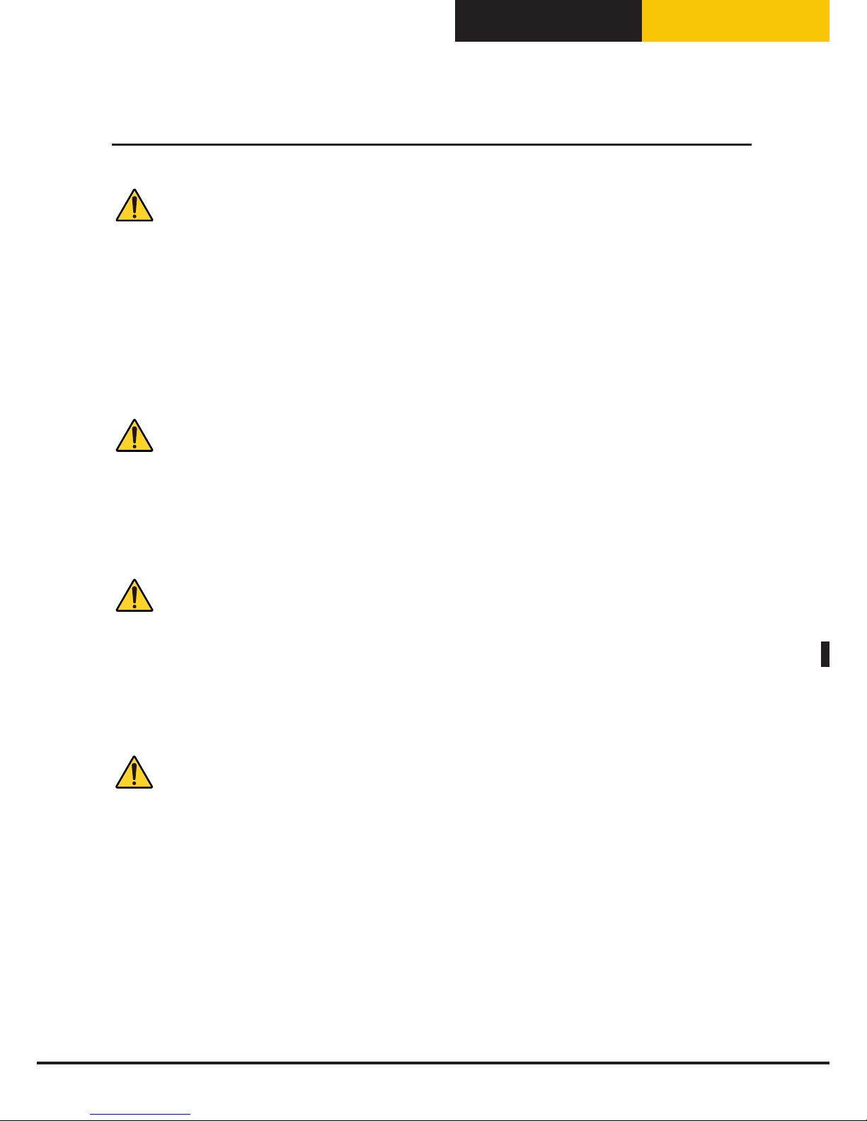
Align the appliance horizontally.
Make sure the appliance is level.
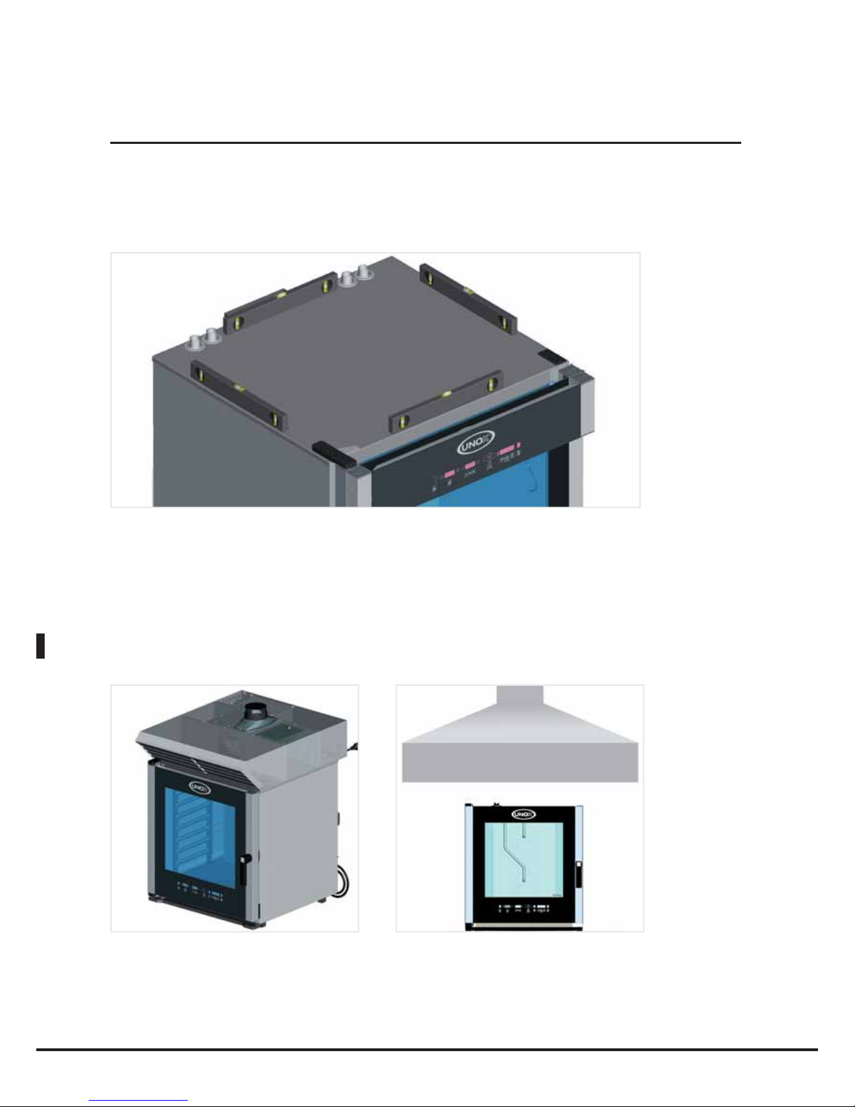
During cooking, hot smoke is produced, along with other odours which need to be removed from the flue;
it is therefore advisable to position the oven underneath a suitable cooker hood, or to use the special UNOX
hoods and ensure the fumes are channelled outside.
36
Positioning
Page 37

English
BakerTop
™
ChefTop
™
Positioning
Door closure regulation
Models without trolley
If, once the oven is in position, the door handle does not remain in its correct closed position (Fig. 1), the
closure latch probably needs to be adjusted; proceed as follows:
• while the oven door is open (Fig. 2), slightly loosen the screws fixing the latch in place (Fig. 3);
• close the door again and turn the handle to stop it from opening (Fig. 3);
• if the door stays shut with the handle in a perfectly vertical position, open the door again (Fig. 4) and tighten
the latch fixing screws (Fig. 5);
• if the problem persists, repeat this procedure, loosening the latch fixing screws further.
2 3 451
Trolley models
In case, once the oven has been placed, the door handle of the oven does not correctly close in vertical
position (pic.1), it may be necessary to fix the door spring latch position. Proceed as follows:
• open the oven door and loose the upper and lower spring latch fixing screws (pictures 2 and 3)
• lightly loose the 2 central spring latch fixing screws (picture 4)
• draw the door up to the spring latch and move vertically the position of the latch in order to make it
perfectly lined up with the door closing pin (picture 5)
• tight the upper, lower and central spring latch fixing screws and try to close the door.
• if the door closes properly and the handle perfectly stays in vertical position, open the door and tightly
fix the fixing screws of the latch.
• in case the problem is not solved, repeat the procedure and loose more the spring latch fixing screws .
23451
N.B
A support surface which is not perfectly even will not allow the door handle to close correctly: if the surface is
only slightly uneven, the problem may be overcome by adjusting the closure latch using the method described
previously; there is no way of compensating for a highly uneven floor or oven support surface.
37
Page 38
English
The support surface must be flat and level. The installation site must be able to withstand the weight of the
appliance and the maximum load. Please refer to the table below:
UNIT/MODEL Weight (without load) UNIT/MODEL Weight (without load)
ChefTop™ elettrici ChefTop™ gas
XVC 055 35 kg - -
XVC 105/ 105P 45 kg - -
XVC 205 41 kg - -
XVC 305/ 305P 59 kg XVC 315G 73 kg
XVC 505/ 505P 76 kg XVC 515G 90 kg
XVC 705/ 705P 83 kg XVC 715G 97 kg
XVC 1205 150 kg XVC 1215G 170 kg
XVC 2005 165 kg XVC 2015G 185 kg
BakerTop™ elettrici BakerTop™ gas
XBC 405 60 kg - -
XBC 605 86 kg XBC 615G 106 kg
XBC 805 118 kg XBC 815G 132 kg
Once the appliance has been positioned, make sure that there is no danger of it slipping or tipping over.
Caution!
If the appliance is to be mounted on a mobile support frame or cabinet, it should be secured with an extra
chain or rope to stop it from rolling around and damaging the electricity or gas supply lines.
Positioning
38
Page 39

English
BakerTop
™
ChefTop
™
Trolley models
Preliminary action – Trolley Extraction
The trolley is positioned inside the oven and fixed with two lateral screws in order to ensure a safe
transport. Before removing the trolley, unfix the two screws as shown on the picture:
Feet adjusting for trolley inserting
To ensure the correct positioning of the trolley inside the oven it’s necessary to check and possibly adjusting
the feet height.
One of the two frontal feet must be fixed to ensure the basic height already pre setted to 173 mm. Looking
one of the frontal fixed foot the other three can be therefore adjusted. See the example bellow:
173 mm
-12
+12
Make sure that the diagonal lengths of the oven opening are identical.
If they are not, fix the adjustable feet as necessary.
Caution!
Make sure that the tray rack trolley can move easily and that there is no
obstruction when sliding it into and out of the oven: sudden movements
may result in hot liquid or food spilling out, which could cause burns.
Positioning
39
Page 40

English
Inserting the trolley and positioning the door closure panel:
To insert the tray rack trolley into the oven, slide it in using the runners on the underside of the oven.
Caution!
The trolley may be hot, and should only be handled while wearing suiable protective garments.
On the central lower part of the oven front there is a micro switch; the oven turns of only when the trolley is
placed inside the cooking chamber or when the door closing panel is placed as described here above.
It is suggested to use the door closing panel during pre-heating or washing programs.
To the door closing panel positioning proceed as follows:
A B C D
1
3
2 4
- Open the oven door and hook the panel (1) by making the lateral holes (2) matching the hooks (3) on the
lower front of the oven (Pictures A, B, C).
- As the drip tray is full, wait for the oven to cool down, grasp the drip tray by the hand grip (4) and empty it
over the drain placed on the bottom of the oven cooking chamber (Picture D).
Caution! the drip tray back surface may be hot and cause burns.
BakerTop trolleys are not equipped with drip tray while ChefTop trolleys have the drip tray as standard
feature. For this reasong it is suggested to use the door closing panel, being equipped with a drip tray collects
the liquids that condense on the internal glass of the oven door.
40
Positioning
Page 41

English
BakerTop
™
ChefTop
™
Caution!
If the floor is not flat, use an entrance ramp with a maximum angle of 4 degrees.
Max.
4°
Max.
2°
Caution!
If the entrance ramp angle is exceeded, hot liquid may spill out of the containers.
Risk of burns!
Caution!
A tray rack trolley which has not been positioned correctly may cause the appliance to malfunction.
When the front part of the trolley has been loaded, it may become slightly lower. Make sure that the trolley
can be moved into and out of the oven easily, without scraping the lower surface of the oven cavity. If this
occurs, adjust the feet and lower the appliance as necessary, so that the trolley can move correctly.
Caution!
Make sure that the tray rack trolley can move easily and that there is no obstruction when sliding it into and
out of the oven: sudden movements may result in hot liquid or food spilling out, which could cause burns.
41
Positioning
Page 42
English
Warning
Connection to the electricity mains must be carried out in compliance with current regulations.
The appliance must be positioned so that the power plug is accessible (for appliances fitted with Schuko plugs).
Means for disconnection must be incorporated in the fixed wiring in accordance with the wiring rules.
We recommed the use of a safety switch for fault currents.
During appliance operation, the power supply voltage should not deviate from the nominal voltage value
specified on the appliance rating plate.
Caution!
Electrical connections must be performed by technicians registered with the relevant authorities as required
by law for the country in which the appliance is installed. These technicians must, nevertheless, be aware of
and apply the regulations relating to the safety of repaired products and safety in the workplace. In light of the
above information, UNOX accepts no responsibility for any situation resulting from work carried out in an
unprofessional manner, or from the incorrect intepretation or application of regulations.
Caution!
Observe the colour coding of the wires. Incorrect connection may lead to electric shocks.
Incorrect connection may damage the appliance.
Wire colour coding:
Yellow/green = protection (earth) wire
Blue = neutral wire
Brown, grey or black = phase L1, L2, L3
For gas-powered appliances:
Caution!
Observe the electrical connection poles.
If the poles are inverted, the burner will not work.
Caution!
Always observe local standards and legislation.
42
Electrical connections
Page 43

English
BakerTop
™
ChefTop
™
Before connecting the oven to the electricity mains, compare the power supply data with the appliance
requirements specified on its rating plate.
If the voltages and power supply phases are different, adjust and correct the phase wiring, in accordance
with the data provided on the attached leaflets. Make sure no electricity is dispersed between the phases and
earth. Make sure there is electrical continuity between the outer casing and the electricity mains earth wire.
We recommend the use of a digital multimeter when performing these procedures.
Caution!
Make sure all electrical connections are secure before connecting the appliance to the electricity mains.
1. Ovens fitted with Schuko plug and cable (single phase): simply insert the plug into the relevant socket (the
socket should be suitable for use with the plug supplied);
2. Ovens fitted with a (three-phase) cable attached to the terminal board in the figure: these ovens are supplied
with a 5-wire electricity cable and leave the factory having been set up for three-phase connection with neutral;
the cable should be connected directly to a switchboard. Means for disconnection must be incorporated in the
fixed wiring in accordance with the wiring rules.We recommed the use of a safety switch for fault currents.
During appliance operation, the power supply voltage should not deviate from the nominal voltage value specified
on the appliance rating plate.
To carry out other types of connection, please refer to the "Technical data" attachment to check the connection
methods used for the oven model in question, as well as the type of cable that should be used.
Connection diagrams can be found on the inside of the terminal board cover.
Only perform the connections indicated on the technical data sheet, fitting the copper jumper and electricity cable
underneath the screw in its tightening direction, so that when the screw is tightened, the cable and jumper are
tightly secured.
3. Ovens fitted with a three-phase terminal board on a DIN bar: to connect the oven electrically, please refer to
the "Technical data" attachment in order to check the connection methods used for the oven model in question,
as well as the type of cable that should be used; for teminal board connection, open the lower part of the oven
back panel and run the power supply cable through the relevant cable clamp.
Only perform the connections indicated on the technical data sheet.
The appliance should be connected directly to a switchboard. Means for disconnection must be incorporated in
the fixed wiring in accordance with the wiring rules. We recommed the use of a safety switch for fault currents.
During appliance operation, the power supply voltage should not deviate from the nominal voltage value specified
on the appliance rating plate.
1. 2. 3.
43
Electrical connections
Page 44

English
44
The cable must only be replaced by authorised personnel. The earthing cable must be yellow and green.
To replace the power supply cable (if using a terminal board with a pre-installed cable), proceed as follows:
• Open the terminal board cover by removing the fixing screws
• Connect the wires in accordance with the selected connection diagram
• Secure the cable using the relevant cable clamp
• Close the terminal board cover and tighten the fixing screws
Caution!
The power supply cable may only be replaced by the manufacturer, a representative from the Assistance
Service or a similarly qualified member of staff.
Incorrect connection may cause the terminal board to overheat so much that it melts.
In light of the above information, UNOX accepts no responsibility for any situation resulting from work carried
out in an unprofessional manner, or from the incorrect intepretation or application of regulations.
The appliance must be connected to the electricity mains earth conductor.
Equipotential connection
The appliance must be included in an equipotential system, which has been checked for efficiency in accordance
with the specifications set out in current regulations.
This connection must be performed between different appliances, using the terminal marked as equipotential.
The equipotential wire must have a minimum cross-section of 10 mm2 and must be yellow and green.
44
Electrical connections
Page 45

English
BakerTop
™
ChefTop
™
45
Warning
Caution!
Install the appliance in areas with adequate ventilation to prevent the formation of toxic substances. Suffocation
hazard!
For information relating to ventilation installation and minimum cross-sections, please refer to current
installation and safety regulations (and subsequent amendments) for the country in which the oven is installed.
Take extra care to ensure that the volume of air required for combustion is not in any way obstructed by
objects placed underneath or around the appliance (and especially near the ventilation openings).
Always make sure the airflow is sufficient, in order to ensure that combustion takes place properly and that
the exchange of air (essential for room hygiene) takes place efficiently.
Caution!
Connection to the gas supply, any work required on the gas circuit inside the appliance and all procedures
relating to the channelling of exhaust gases must be performed by technicians registered the relevant authorities as required by law for the country in which the appliance is installed. These technicians must, nevertheless, be aware of and apply the regulations relating to the safety of repaired products and safety in the
workplace. In light of the above information, UNOX accepts no responsibility for any situation resulting from
work carried out in an unprofessional manner, or from the incorrect intepretation or application of regulations or this manual.
To ensure that the standard appliance settings correspond to the actual connection conditions, the first time
the appliance is operated it will be necessary to perform an analysis of the burner exhaust gases, steam and
hot air (CO, CO2), recording the measured values on the appliance.
If the undiluted CO value is greater than 1000 ppm, the burner setting should be checked and, if necessary,
adjusted by a technician authorised by the company, in accordance with the setting instructions.
Caution!
Unsuitable connection may present a fire hazard.
Observe the standards established by the local gas authority.
Make sure the type of gas available corresponds to the type indicated on the appliance.
Do not obstruct or place anything on the combustion gas exhaust located at the top of the appliance.
Caution!
Gas connection must only be performed by an authorised installer from the local area.
Always make sure the gas connection pipes, and any pipes used in relevant measuring systems, comply with
the size indications provided.
All parts not supplied by UNOX must be approved in accordance with current regulations.
If the pipe pressure differs from the connection flow pressure, contact the local gas authority.
If the natural gas connection flow pressure is over 30 mbar, the appliance cannot be operated and the gas
part must be shut off.
Caution!
The gas system components are designed for a maximum connection flow pressure of 60 mbar. Higher
operating pressure values are not permitted.
45
Gas connections
Page 46

English
SEAL TEST
All the connections between the water supply and the equipment have to be tested for the seal.
It is suggested to use a leak finder spray or, if not available, it is possible to brush the connection points with
proper non corrosive foams.
In both cases no leakages have to be detected (bubbles).
Do not use free flames to test the connections seal!
Combustion gas disposal
The gas oven models can be grouped into three categories on the basis of the method used to dispose of
combustion gases:
A1 type (for ovens with thermal power < 14 kW): exhaust gases can be released into the room in which
the oven is installed.
B11 type (for ovens with thermal power > 14 kW): exhaust gases must be released outside the room
in which the oven is installed, by means of a natural ventilation flue wth proven efficiency. For this type of
installation, make sure that the entire length of the flue has a cross-section which is no smaller than that of the
appliance exhaust pipe attachment. There must be a vertical duct above the ventilation switch; this must be at
least 3 times as long as the diameter of the pipe.
The exhaust system must follow an upward trajectory at a minimum incline of 10%, and must incorporate
no angles smaller than 90 degrees. The horizontal part of the smoke exhaust connection must not exceed
1.5 metres in length. If connection is impossible, use a cooker hood positioned no less than 50 cm away from
the ventilation switch: if positioned too near, it may cause an excessive drop in pressure when the ventilation
switch is activated, which could cause a greater amount of gas to be drawn out from inside the burner; this in
turn could lead to explosions and the production of toxic unburnt gas.
Caution!
We recommend a flue cover is installed on top of the external end of the flue, to prevent rainwater from
getting into the oven and to minimise pressure drops caused by the Venturi effect, which can occur when the
flue is subject to strong outside air currents.
46
Gas connections
Page 47

English
BakerTop
™
ChefTop
™
B21 Type (for ovens with thermal power > 14kW): exhaust gases are released outside by means of a
cooker hood. The cooker hood should be positioned at least 50 cm away from the ventilation switch: if positioned too near, it may cause an excessive drop in pressure when the ventilation switch is activated, which
could draw a greater amount of gas inside the burner; this in turn could lead to explosions and the production
of toxic unburnt gas.
Caution!
To ensure that the standard appliance settings correspond to the actual connection conditions, the first time
the appliance is operated it will be necessary to perform an analysis of the burner exhaust gases, steam and
hot air (CO, CO2), recording the measured values on the appliance.
If the undiluted CO value is greater than 1000 ppm, the burner setting should be checked and, if necessary,
adjusted by a technician authorised by the company, in accordance with the setting instructions.
min. 500 mm
Caution!
We recommend a flue cover is installed on top of the external end of the flue, to prevent rainwater from
getting into the oven and to minimise pressure drops caused by the Venturi effect, which can occur when the
flue is subject to strong outside air currents.
Combustion gas exhaust type selection must take place in accordance with the provisions set out by local
legislation relating to the installation of gas appliances.
All ovens are fitted with a wind-resistant flue, which is built into the combustion gas exhaust circuit and is
activated in the event of an obstruction or if an unusual draught occurs: this flue is an integral part of the oven
and should never be removed.
Caution!
The temperature of the exhaust gases may exceed 500°C.
Given the high temperature of the exhaust gas, the exhaust gas piping must not be made using aluminium or
any materials which cannot withstand temperatures up to 200°C.
Caution!
Exhaust piping must be inspected and approved by a specialist, in compliance with current local regulations
and standards.
It is recommended that written documentation is issued after the inspection has been completed.
47
Gas connections
Page 48

English
Warning
Before performing the connection, the qualified installer should make sure that the data specified on the
appliance rating plate corresponds to the data for the type of gas available.
The appliance is calibrated, set up and tested in the factory for LPG gas (G30/G31 butane/propane)
Caution!
Connection to the gas supply, any work required on the gas circuit inside the appliance and all procedures
relating to the channelling of exhaust gases must be performed by technicians registered with the relevant
authorities as required by law for the country in which the appliance is installed. These technicians must, nevertheless, be aware of and apply the regulations relating to the safety of repaired products and safety in the
workplace. In light of the above information, UNOX accepts no responsibility for any situation resulting from
work carried out in an unprofessional manner, or from the incorrect intepretation or application of regulations
or this manual.
Connections
T|he appliance must be connected in compliance with current regulations for the country in which it is installed.
The appliance must be fitted with an upstream shut-off valve, in an easily accessible location.
Connection to the gas supply, by means of the ¾” ISO 7-1 attachment on the bottom left-hand side of the
back panel of the oven, may be carried out using rigid pipes or flexible hoses and by fitting an approved shutoff valve.
If flexible hoses are used, they must be made using steel; you will have to make sure that they are not placed
near hot areas and are not subjected to twisting and/or traction.
If using non-metallic materials (i.e. for the seals), they must be suitably certified and should conform to current
European regulations. Finally, make sure that there are no leaks in the gas circuit by feeding a soapy water
solution or a special foaming product through the connections. Never use a naked flame to look for gas
leaks.
48
Gas connections
Page 49
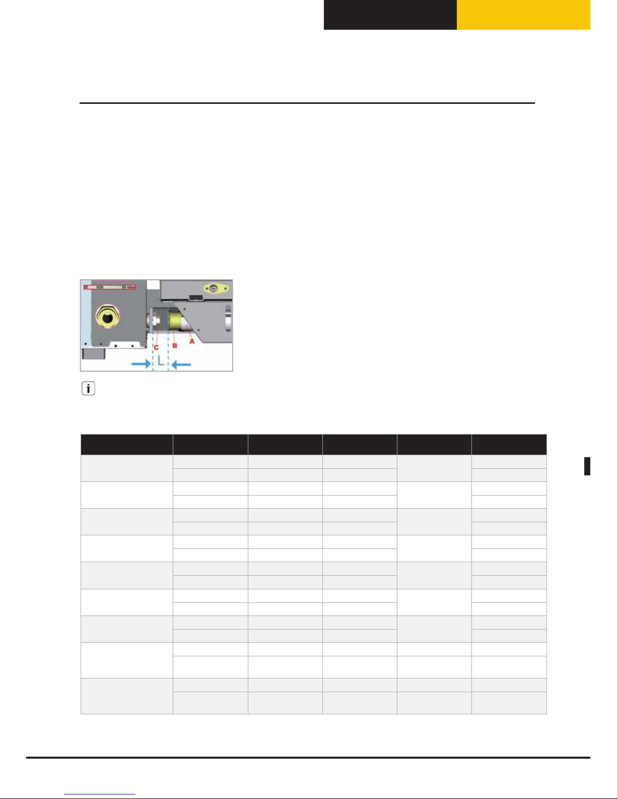
English
BakerTop
™
ChefTop
™
Gas Setup
The gas type in the gas pipe network must be checked by a qualified technician that, if necessary, replaces
the nozzle, adjusts the primary air and sets the type of gas on the oven control panel and apply the label.
Nozzle replacement and primary air adjustment
Using the table in the attached technical data sheet, replace the main injector and adjust the primary air using
the corresponding bushing. This procedure should only be carried out once the gas valve upstream of the
oven has been shut off and the power supply disconnected. Make sure that the diameter measurement of the
injector to be replaced is stamped on it, in hundredths of a millimetre (1/100 mm). The injector is located at
the rear, on the bottom left-hand side. To replace the injector and adjust the primary air, proceed as follows
(see illustration below):
• Loosen screw A.
• Adjust bushing B in accordance with the information provided in the
attached table.
• Unscrew and remove injector C using a 13 mm spanner.
• Install the injector most suited to the type of gas supplied (see relevant
technical table).
• Position bushing B at the correct distance H (see relevant technical table).
• Re-tighten screw A.
There are 2 types of nozzle:
- one suitable for G20, G25 and G25.1 gas
- one suitable for G30 and G31 gas
OVEN GAS NOZZLE CODE
NOZZLE DIAMETER
[1/100 mm]
PRIMARY AIR
L [mm]
INSTALLATION
XBC 615 G
G20, G25, G25.1 BR1275A0 345
All open
L=39 mm
In the appliance
G30,G31 BR1055A0 225 Installed
XBC 815 G
G20, G25, G25.1 UG1001A0 375
All open
L=39 mm
In the appliance
G30,G31 BR1250A0 245 Installed
XVC 315 G
G20, G25, G25.1 BR1020A0 280
All open
L=39 mm
In the appliance
G30,G31 BR1085A0 185 Installed
XVC 515 G
G20, G25, G25.1 BR1270A0 335
All open
L=39 mm
In the appliance
G30,G31 BR1150A0 220 Installed
XVC 715 G
G20, G25, G25.1 BR1280A0 360
All open
L=39 mm
In the appliance
G30,G31 BR1180A0 230 Installed
XVC 1215 G
G20, G25, G25.1 BR1275A0 345
All open
L=39 mm
In the appliance
G30,G31 BR1055A0 225 Installed
XVC 2015 G
G20, G25, G25.1 UG1001A0 375
All open
L=39 mm
In the appliance
G30,G31 BR1250A0 245 Installed
XVC915G - XVC1015G
XBC915G - XBC1015G
G20, G25, G25.1 BR1245A0 355 L=39 mm In the appliance
G30,G31 BR1055A0 225
All open
L=39 mm
Installed
XVC3215G - XVC4015G
G20, G25, G25.1 BR1245A0 355 L=39 mm In the appliance
G30,G31 BR1055A0 225
All open
L=39 mm
Installed
Gas connections
49
Page 50

English
50
Gas parameter modify at control panel
Change the gas type setting by entering the 2nd level hidden menu of the oven control panel, as follows:
1. To enter the hidden menu, press simultaneously the
-
+
-
buttons for 5 seconds
2. Press the
button until the display shows: 12 – FrU – 10:
3. Press the button until the display shows the GAS parameter
4. Use
-
+
-
buttons to select the correct gas type setting : G20, G25 or G30 (includes G31).
5. Press
button to save the new setting
6. Press
button to exit hidden menu
7. To store the new settings disconnect the oven (unplug it), wait for 10 seconds and then re-connect it
Caution!
After each adjustment to a new type of gas:
• Apply a permanent label to the rating plate, specifying the data relating to the new fitting:
• Seal the adjusted parts again.
• Check the gas circuit for leaks.
• Carry out a general operational check.
• Check if the pressure outlet of the oven gas valve respects the values indicated in the table below:
GAS
p max
[mbar]
p min
[mbar]
G20 14.2 ± 2% 5
G25 (G25.1) 21.2 ± 2% 7.5
G30 (G31) 26.2 ± 2% 10
Gas connections
Page 51
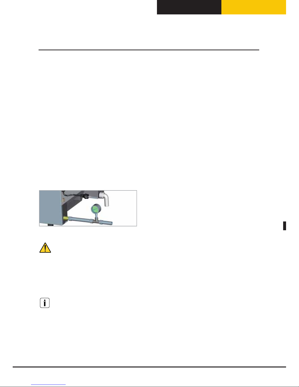
English
BakerTop
™
ChefTop
™
51
Checking the nominal heating capcity
The heating capacity should be checked by authorised personnel or the responsible organisation, on the basis of the data
provided in this operating manual. This check should be performed for new installations, transformations or adaptations
to other types of gas, and after every maintenance procedure.
The nominal heating capacity and connection pressures can be obtained using the technical data table. Components
sealed with red paint must never be adjusted. The specified nominal heating capacity is obtained using the nozzles as described
in the correpsonding table in the Technical data booklet, at the connection pressure specified for each type of gas.
If you wish to carry out a further nominal heating capacity check, it can be performed using the volumetric method, by
means of a meter and a timer. The exact volume which should pass through per time unit can be found in the correspinding
table in the Technical data booklet. This connection value should be maintained in the specified area, with a tolerance of ±5%.
If any deviations are detected, you should make sure that the nozzles fitted have the correct diameter and are being used with
the correct inlet pressure.
Checking the connection pressure
The connection pressure should be measured while the appliance is in operation, using a fluid pressure measuring device
(for example, a "U"-shaped pressure gauge with a resolution of 0.1 mbar or an electronic pressure gauge); make sure the
recorded pressure value
matches the value provided in the corresponding table.
To check the inlet pressure, shut off the upstream gas valve and remove the gas supply pipe, inserting a T-fitting between
this pipe and the gas inlet of the oven; connect a suitable pressure gauge to the free terminal on the T-fitting and record
the reading. The inlet and outlet pressure values can be taken also on the two plugs in the gas valve, proceed as follows:
remove the protection guard and connect 2 flexible tubes to the pressure plugs of the valve and the pressure measurer.
Before making the above operations take off the fixing screws of the pressure plugs and disconnect the appliance from
the power supply.
If the recorded pressure value is much lower than the the value indicated in "CHART A" (more than 0.2 mbar below
the value
indicated in the table), contact your local gas supplier.
Caution!
Solenoid valve components which have been adjusted and sealed by the manufacturer should not be tampered with for
any reason.
Operational check
Start the appliance in accordance with the operating instructions. Make sure the appliance does not leak.
Check the formation, cross-lighting and appearance of the flames through the burner venilation openings; it is particularly important that the flames are strong and bright blue in colour, with no yellow tips.
User recommendations
The technician responsible for installation must instruct the customer/user on the fundamental safety aspects regarding
oven operation, referring to the information contained in this "Instruction manual" supplied with the oven. Every nonroutine maintenance procedure (replacing malfunctioning components, adapting to other gases, etc.) must be performed
by a technician with the necessary professional qualifications; once these procedures have been completed, a general
operational check of the oven is required.
For this reason we recommend a maintenance contract is drawn up, stipulating that the appliance is inspected - and the
electrical, gas and plumbing connections thoroughly checked - at least twice a year.
The end user accepts full responsibility for the daily operation and cleaning of the appliance.
Gas connections
Page 52

English
52
Plumbing: water supply
Warning
A shut-off valve and a mechanical filter should be positioned between the water mains and the appliance.
The appliance is supplied with 2 metres of piping at the corresponing attachment (3/4”) with non-return valve
and mechanical filter, as required by current reglations.
Before connecting the water pipe to the appliance, flush it out with water in order to eliminate any residue
which has accumulated inside it.
The pressure value of the water supply at the inlet should be between 150 and 400 kPa; its temperature must
be no higher than 30°C.
The appliance has an internal pressure reducer which is calibrated to 2 bar, in order to ensure the correct
amount of steam is produced by the STEAM.Maxi™ system, thereby guaranteeing optimal cooking results.
If the pressure of the water supply at the inlet is too low, a pump with a suitable flow rate should be used.
WATER IN
If connection to the water mains is not possible, the steam circuit of the oven can be fitted with the XC665
kit, which draws distilled water from a jerry can or another type of container.
Water supply quality
The water supplied to the STEAM.Maxi™ circuit must have a maximum hardness of 100 μS/cm.
The use of a deioniser (reverse osmosis) is strongly recommended, in order to prevent limescale and/or other
mineral deposits from building up inside the oven.
As such, you may take the opportunity to use the UNOX reverse osmosis system, code XC235, which is directly
controlled by means of a self-diagnosis system implemented by the electronic control panel of the oven.
User recommendations
Any damage caused by limescale or other chemical agents carried by the water is not covered by the
guarantee.
STEAM.Maxi™ plumbing
Page 53

English
BakerTop
™
ChefTop
™
53
Plumbing: water drainage
Warning
The waste water flowing out of the oven may be hot (90°C).
The pipes used for water drainage must be able to withstand high temperatures.
Pipes
In the bag inside the packaging, you will find a 90° bend that can be fitted to the water drainage terminal on
the back of the oven, and should then be connected using a rigid pipe or flexible hose (see UNOX kit, code
TB1520) leading to an open or siphon drain. Its diameter should be at least equal to the diameter of the drain
attachment, and it should be no longer than one metre.
The oven drainage channel should be connected to the waste water system by means of a suitable siphon, in
order to prevent steam from escaping.
Avoid crushing flexible hoses or letting kinks form in metal pipes, for the entire length of the drain channel.
T|he drain pipe must always be at an incline of at least 5% to guarantee an adequate flow of water, and the
almost horizontal section should be no longer than one metre.
It is good practice to make sure each appliance has its own connection to the water drainage system. If
several appliances or other pieces of equipment are connected to a single drainage pipe, make sure that the
pipe is large enough, so as to ensure the water flows away properly without any problems.
min. 4°
25 mm
max. 2000 mm
min. 4°
min. 4°
25 mm
Attention!
All the operations must be carried out according to local current laws and regulations.
The drain has to be placed outside the perimeter of the equipment.
Do not reduce the diameter of the drain pipe.
STEAM.Maxi™ plumbing
Page 54
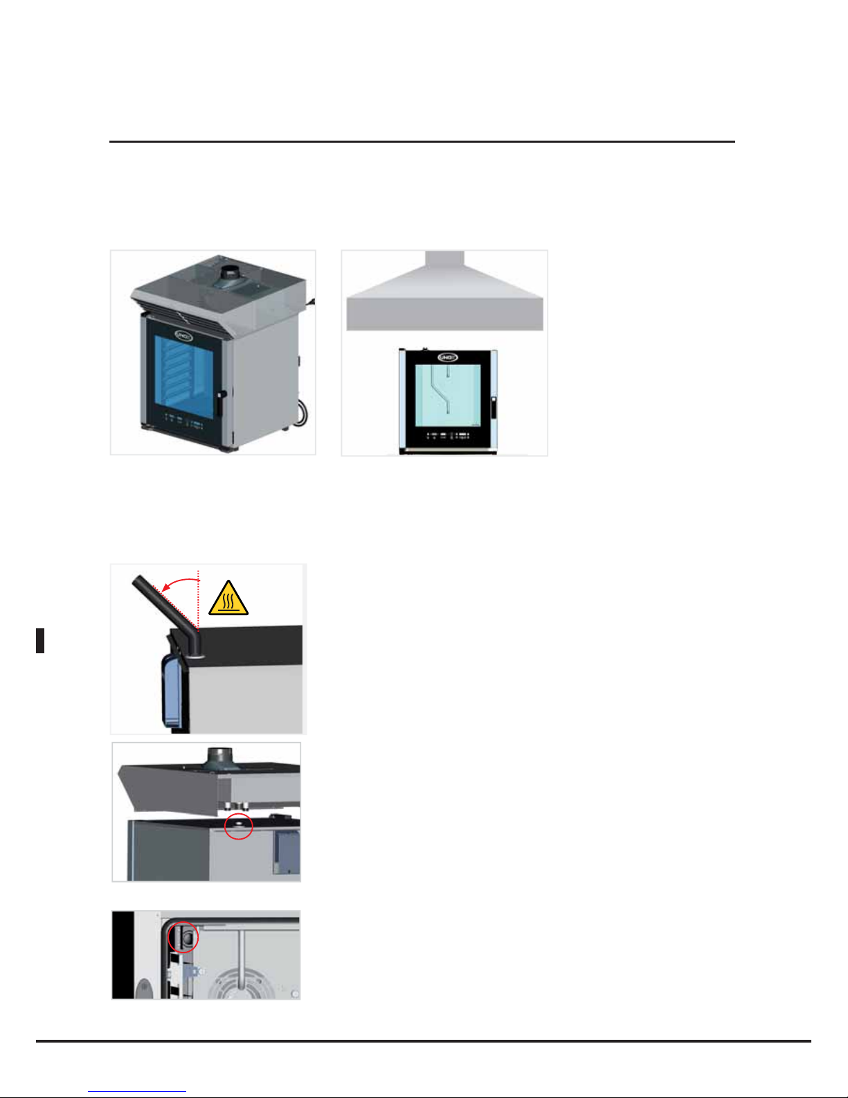
English
During cooking, hot smoke is produced, along with other odours which need to be removed from the flue(s);
it is therefore advisable to position the oven underneath a suitable cooker hood, or to use the special UNOX
hoods and ensure the fumes are channelled outside.
The oven cavity smoke exhaust is located at the top of the back panel of the oven.
Do not place objects and/or materials over the smoke exhausts, as this could compromise the normal
channelling of the fumes. Make sure that there are no objects/materials on top of the smoke exhaust which
could be damaged by the fumes.
Do not leave flammable materials near the smoke exhausts.
If you wish to channel the fumes using a pipe which does not feature
ventilation or forced expulsion, a separate pipe (with a diameter of at
least 30 mm) must be provided for each flue. None of these should
exceed one metre in length; they should all have a minimum incline of
45° in relation to the ground.
We therefore recommend that the oven is positioned underneath the
UNOX cooker hood, code XC315 (for the ChefTop™ GN 1/1 series),
XC415 (for the BakerTop™ series) or XC515 (for the ChefTop™ and
BakerTop™ trolley series). Alternatively, install the UNOX steam
condenser, code XC115, or channel the fumes using the UNOX pipe,
code TB1520, taking care not to crush it.
There should be no restrictions along the drain pipe tract.
N.B for BakerTop ovens:
For BakerTop™ ovens to ensure a greater humidity extraction from
the cooking chamber it is suggested to install inside the chamber the
two metal plates supplied together with the oven, positioning them
beside each exhaust fumes with the proper screws. See the example.
54
Oven cavity smoke exhaust
max. 1m
max. 45°
Page 55

English
BakerTop
™
ChefTop
™
The oven control P.C.B. manages all accessories (hood, holding cabinet, blast chiller, osmosis system).
The accessories controlled by the oven are connected to that oven by means of the RJ45 connectors on the
rear of the appliance.
To connect the oven to the relevant accessories, proceed as follows:
• Disconnect all appliances from the electricity mains
• Remove the rear panel in order to access the internal electrical system
• Use a cutter to make a vertical slit in one of the rubber caps on the panel behind the oven
• Thread one end of the RJ45 cable through the slot
• Insert the end of the cable into the corresponding female connector on the power P.C.B. (it does not
matter which of the three connectors is used)
• Replace the protective cover and tighten the screws
• Reconnect all the appliances to the electricity mains
Connected accessories will be recognised automatically and can be controlled via the oven control panel.
For further information relating to the operation of accessories, please refer to the instruction manual for
the accessory in question.
Caution!
Electrical connections and any work carried out on the electrical system of the oven, as well as the electrical
connection of the oven to the relevant accessories, must be carried out by technicians registered with the
relevant authorities as required by law for the country in which the appliance is installed. These technicians
must, nevertheless, be aware of and apply the regulations relating to the safety of repaired products and
safety in the workplace. In light of the above information, UNOX accepts no responsibility for any situation
resulting from work carried out in an unprofessional manner, or from the incorrect intepretation or application
of regulations.
55
Connection of accessories
Page 56

English
Caution!
The oven should never be placed immediately above other ovens or other sources of heat.
If several ovens need to be stacked in a column, use the UNOX stacking kit, code XC726 (for the ChefTop™
GN 2/3 series), XC727 (for the ChefTop™ GN 1/1 series), or XC725 (for the BakerTop™ 600x400 and
ChefTop™ GN 2/1 series) to maintain the correct distance between the ovens and to facilitate the electrical,
plumbing and exhaust connection procedures.
Oven stacking
56
Page 57

English
BakerTop
™
ChefTop
™
Certification
Manufacturer: UNOX S.p.A.
Address: Via Dell’Artigianato, 28/30 - I - 35010 - Vigodarzere, Padua, Italy
Product: Combined oven for professional use
Family: ChefTop™ – BakerTop™
REFERENCE STANDARDS
The "CE" mark on the appliances named in this manual refers to the following directives:
Low Voltage directive 2006/95/EC, in accordance with standards:
EN 60335-2-42:2003 + A1:2008 used in conjunction with
EN 60335-1:2002 + A11:2004 + A1:2004 + A12:2006 + A2:2006 + A13:2008
EN 62233:2008
Electromagnetic Compatibility directive 2004/108/EC, in accordance with standards:
EN 55014-1:2006
EN 55014-2:1997 + A1:2001
EN 61000-3-2:2006
EN 61000-3-3:1995 + A1:2001 + A2:2005
EN 61000-3-11:2000
Gas Appliances Directive 90/396/CEE, following the rules and current updating:
EN 203-1
EN 203-2-2
EN 437
57
Page 58
Italiano
Spiegazione dei pittogrammi
2
Pittogrammi generici
Pericolo!
Situazione di pericolo immediato o situazione pericolosa che potrebbe causare lesioni o
decesso.
Pericolo d’incendio!
Pericolo alta tensione!
Pericolo sostanze corrosive.
Pericolo ustioni
Attenzione: una mancata osservanza può causare danni materiali
Consigli utili per l’uso quotidiano
Informazioni
Page 59

Italiano
BakerTop
™
ChefTop
™
Sommario
Spiegazione dei pittogrammi 2
Sommario 3
Introduzione 4
ISTRUZIONI PER L’UTILIZZATORE
- Norme di sicurezza 5-8
Indicazioni per l’uso dell’apparecchio e Garanzia 9
Controllo digitale ChefTouch-BakerTouch 10
- Funzionamento del controllo 11
Impostazione parametri 12-16
Selezione fasi cottura 17
Impostazione cotture
- Cottura con impostazione tempo e temperatura camera 18
- Cottura con sonda al cuore e temperatura camera impostata 19
- Cottura con sonda al cuore e Delta T impostato 20
Programmazione da parte dell'utente 21
Funzionalità di serie
- Funzione LASTP 22
- Programmi lavaggio automatici 22
- Programma raffreddamento camera cottura “COOL” 23
- Funzione ADAPTIVE.Clima 24
Processi di cottura pre-impostati 25
Tecnologia MAXI.Link 26
Principi di cottura 27
Comunicazione forno-utente
- Messaggi di warning (attenzione) 28-29
- Messaggi di allarm (allarme) 29-30
- Manutenzione in caso di guasto 30
ISTRUZIONI PER L’INSTALLATORE
- Norme di sicurezza 31
Istruzioni per il trasporto dell'apparecchio 32
Installazione dell’apparecchio 33-34
Posizionamento 35-41
Allacciamento elettrico 42-44
Allacciamento gas 45-51
Allacciamento idrico 52-53
Scarico fumi camera cottura 54
Collegamento accessori 55
Sovrapposizione forni 56
Certificazioni 57
3
Page 60

Italiano
4
Gentile Cliente,
La ringraziamo e ci complimentiamo con Lei per aver acquistato un forno della linea ChefTop™/ BakerTop™ e ci
auguriamo che questo sia solo l’inizio di una positiva e duratura collaborazione.
Come Lei ben saprà la linea di forni ChefTop™/ BakerTop™, e tutte le attrezzature ad essa complementari
(abbattitore, mantenitore, teglie e griglie speciali), sono state studiate per permetterLe di completare qualsiasi
processo di cottura dal più semplice al più complesso.
L’innovativo pannello digitale Chef Touch Le permetterà di comandare, con un unico controllo, tutte le attrezzature
UNOX collegate al forno.
Il forno ChefTop™ / BakerTop™ da Lei acquistato è dotato dell’esclusiva tecnologia ADAPTIVE.Clima che le dà la
certezza di un risultato sempre identico, indipendentemente dal numero di teglie infornate.
Il forno ChefTop™ / BakerTop™ monitora infatti in modo costante tutti i parametri di cottura, non solo la
temperatura ma anche la reale umidità presente in camera, permettendoLe di ottenere ad ogni infornata il
risultato desiderato con la garanzia di una cottura sempre perfetta. La tecnologia ADAPTIVE.Clima Le consentirà
inoltre di ripetere un processo di cottura memorizzato infinite volte e avere la certezza di un risultato sempre
identico, indipendentemente dal fatto che il forno lavori con tutte le teglie o con una sola teglia.
La tecnologia AIR.Maxi con la possibilità di impostare 3 diverse velocità di rotazione del motore e tre funzionamenti
semi-statici Le permetterà di impostare i flussi di aria all’interno della camera a seconda delle Sue esigenze: da
veloci per cotture intense e rapide a lenti per cotture di cibi delicati e leggeri, per arrivare fino ai funzionamenti
semistatici per poter gestire con facilità anche le più difficili cotture di pasticceria e panificazione.
La tecnologia MULTI.Time Le permetterà inoltre di settare fino a 9 timer dandoLe la possibilità di avere sempre
il massimo controllo anche nel caso di cotture multiple di cibi che, a parità di temperatura e umidità di camera,
richiedono tempi di cottura differenti.
Nel caso abbia scelto di dotare il suo forno ChefTop™/ BakerTop™ di due sonde al cuore supplementari ad aghi
extra fini esterne al forno, Le sarà inoltre possibile eseguire perfette cotture sottovuoto e al vapore di alimenti
particolarmente delicati o di piccole dimensioni.
UNOX S.p.A.
Rivenditore: Installatore:
Data di installazione:
Introduzione
Page 61

Italiano
BakerTop
™
ChefTop
™
5
Attenzione
Leggere attentamente il presente libretto in quanto fornisce importanti indicazioni riguardanti la sicurezza e l’uso
del forno. Conservare con cura questo libretto per ogni ulteriore consultazione dei vari operatori.
Norme di Sicurezza
Installazione, assistenza, manutenzione o pulizia errate, nonché modifiche apportate all’apparecchio possono
provocare danni, lesioni o incidenti mortali. Leggere attentamente il manuale d’uso prima di mettere in
funzione l’apparecchio.
Norme generali di sicurezza
Questo apparecchio può essere utilizzato solo per la cottura di cibi nelle cucine industriali e professionali
solo da personale qualificato.
Qualsiasi altro impiego non è conforme all’uso previsto e pertanto pericoloso.
L’apparecchiatura dovrà essere destinata solo all’uso per il quale è stata espressamente concepita, ogni altro
impiego è da ritenersi improprio.
L’apparecchiatura può essere utilizzata per i seguenti impieghi:
- per le cotture di tutti i prodotti di Pasticceria e Pane, freschi o congelati;
- per le cotture di tutti i prodotti di Gastronomia, freschi o congelati
- per ricondizionamento di cibi refrigerati e congelati
- per la cottura a vapore di carni, pesce e verdure
- per la cottura di cibi sottovuoto, in appositi sacchetti adatti alla cottura stessa.
L’apparecchiatura non è adatta all’utilizzo da parte di persone (inclusi i bambini) con ridotte capacità fisiche,
mentali e sensoriali, e con mancanza di esperienza e conoscenza, a meno che essi non siano stati istruiti
sul corretto utilizzo del prodotto e vengano sorvegliati da una persona responsabile della loro sicurezza.
Assicurarsi che i bambini non giochino con l’apparecchiatura.
Non devono essere utilizzati alimenti contenenti sostanze facilmente infiammabili (p.es. cibi a base di alcol).
Le sostanze con un punto di infiammabilità basso possono andare in autocombustione - pericolo d’incendio
e di fenomeni esplosivi nella camera di cottura che possono provocare aperture impreviste della porta,
anche violente.
I detersivi e i decalcificanti, così come i relativi accessori si possono utilizzare solo per lo scopo descritto nel
presente manuale.
Qualsiasi altro impiego non è conforme all’uso previsto e pertanto pericoloso.
In caso di danni alle lastre di vetro che costituiscono la porta, farle sostituire immediatamente.
Pericolo di rotture improvvise.
Per evitare incidenti o danni all’apparecchio, è necessario sottoporre il personale a corsi di formazione e
sessioni sulla sicurezza regolari.
ISTRUZIONI PER L’UTILIZZATORE
Page 62
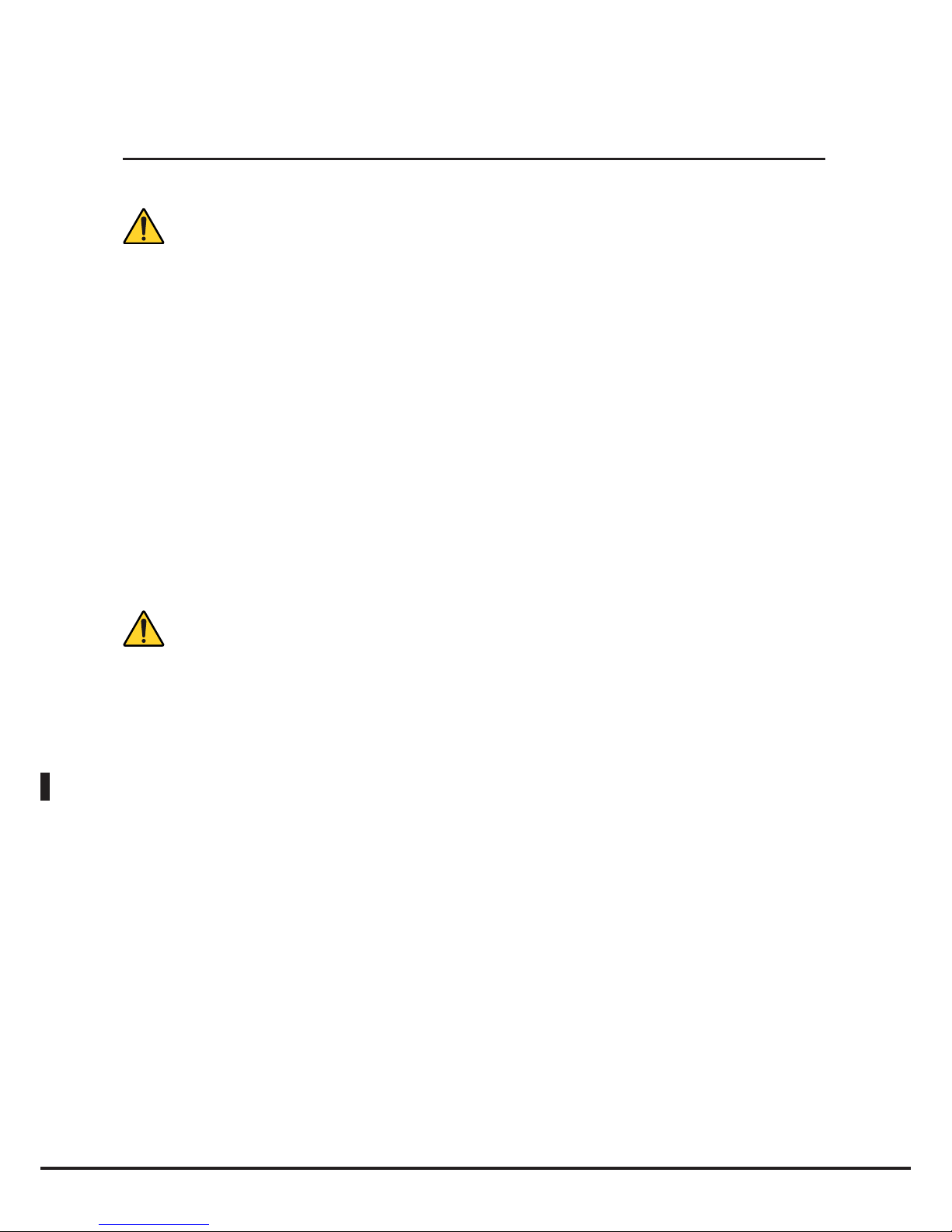
Italiano
6
Norme di sicurezza apperecchi a gas
Se l’apparecchio è installato sotto una cappa di aspirazione, quest’ultima deve essere accesa durante il
funzionamento dell’apparecchio stesso – gas combusti!
Se l’apparecchio è collegato ad un camino, il tubo di scarico deve essere pulito secondo quanto previsto
dalle disposizioni specifiche del paese. (Per informazioni in merito contattare il proprio installatore).
Non collocare alcun oggetto sul tubo dei gas di scarico dell’apparecchio.
La zona sotto l’apparecchio non deve essere bloccata o ostruita da oggetti.
L’apparecchio può essere fatto funzionare solo in un ambiente senza vento.
Comportamento in caso di odore di gas:
Interrompere immediatamente l’alimentazione del gas!
Non toccare alcun interruttore elettrico!
Ventilare bene l’ambiente!
Evitare di produrre fiamme libere e scintille!
Usare un telefono esterno ed informare subito l’azienda del gas competente (se questa non fosse
raggiungibile, contattare il corpo dei pompieri competente)!
Utilizzo: norme di sicurezza
In fase di primo utilizzo assicurarsi che all’interno della camera di cottura non siano presenti libretti di
istruzioni, sacchetti in plastica o quant’altro.
Assicurarsi che telai appesi e carrello portateglie all’interno della camera di cottura siano bloccati come
previsto dalle disposizioni – I contenitori con liquidi caldi possono cadere o scivolare dalla camera di
cottura – pericolo di ustioni!
Prima di utilizzare l’apparecchio per cucinare assicurarsi che nella camera di cottura non siano presenti
residui di detergenti. Rimuovere eventuali residui di detergenti con uno straccio umido e utilizzando
adeguati strumenti di protezione per mani, bocca e occhi e sciacquare a fondo - Pericolo di corrosione!
I pannelli di comando possono essere azionati solo con le dita; qualsiasi altro oggetto può provocare danni
e/o malfunzionamenti e quindi fa decadere la garanzia.
Utilizzare l’apparecchio con una temperatura ambiente compresa tra +5 °C e +35 °C.
La temperatura delle parti esterne può superare i 60 °C: Toccare solo gli elementi di comando
dell’apparecchio. Pericolo di ustioni!
Quando i contenitori sono pieni di liquidi o vengono riempiti di liquidi durante la cottura, non è consentito
utilizzare ripiani più alti rispetto a quello in cui l’utente può vedere all’interno del contenitore – pericolo
di ustioni!
Nel caso di estrazione di teglie contenenti liquidi caldi prestare particolare attenzione all’eventuale
fuoriuscita dei liquidi stessi.
Norme di Sicurezza
Page 63

Italiano
BakerTop
™
ChefTop
™
7
Prestare particolare attenzione alla movimentazione dei contenitori di cibo durante e dopo la cottura: le
temperature possono essere elevate e provocare ustioni.
Toccare accessori e altri oggetti all’interno della camera di cottura calda solo con indumenti termici
protettivi – pericolo di ustioni!
Aprire sempre lentamente e con cautela la porta: pericolo ustioni per fuoriuscita vapori ad alta temperatura.
Estrarre la sonda al cuore dai cibi prima di estrarre la teglia dal forno.
Prima di procedere all’estrazione di contenitori di cibo dalla camera di cottura accertarsi che la sonda al
cuore non sia d’intralcio all’estrazione stessa. Non lasciare pendere la sonda al cuore al di fuori della porta
del forno per evitare danneggiamenti alla sonda e fuoriuscita di vapori o liquidi caldi durante la cottura.
Durante il funzionamento del programma “COOL” (raffreddamento camera) le ventole del forno
funzionano con la porta del forno aperta. Accertarsi che il carter aria sia ben fissato prima di attivare il
funzionamento in modalità “COOL”. Non rimuovere il carter aria durante il funzionamento in modalità
“COOL” del forno e non toccare per nessun motivo le ventole e le resistenze finché il forno è acceso,
oppure quando le ventole sono in moto e/o le resistenze sono ancora calde.
Non riporre sostanze facilmente infiammabili o combustibili nei pressi dell’apparecchio – pericolo d’incendio!
Se apparecchi mobili e carrelli portateglie non vengono spostati, è necessario attivare il freno di
stazionamento delle ruote. I carrelli potrebbero rotolare via in presenza di superfici irregolari – pericolo
di lesioni!
Se i carrelli portateglie vengono spostati ai fini dell’uso, chiudere sempre il bloccaggio dei contenitori.
Chiudere i contenitori con liquidi in modo che non fuoriescano sostanze liquide calde - pericolo di ustioni!
In fase di caricamento e scaricamento del carrello portapiatti e del carrello portateglie, il carrello da
trasporto deve essere fissato conformemente all’apparecchio – pericolo di lesioni!
I carrelli portateglie, i carrelli portapiatti, i carrelli da trasporto e gli apparecchi montati su ruote possono
rovesciarsi durante il trasporto su superfici irregolari o nel varcare la soglia di una porta – pericolo di lesioni!
Evitare di effettuare la salatura dei cibi nella camera di cottura. Se non evitabile, provvedere nel più breve
tempo possibile alla pulizia del forno (vedi paragrafi seguenti).
Norme di Sicurezza
Page 64

Italiano
8
Cura, ispezione e pulizia
E’ consigliabile pulire quotidianamente la camera di cottura per mantenere livelli di igienicità adeguati
e per evitare che l’acciaio inossidabile all’interno della camera di cottura si rovini. A tal proposito si
consiglia l’utilizzo del sistema di lavaggio Rotor.KLEAN™ codice XC405 che permette di eseguire la
pulizia automatica della camera di cottura.
Attenzione!
Se l’apparecchio non viene pulito o non viene sottoposto ad una pulizia sufficiente, è possibile che i grassi o i resti
alimentari accumulati nella camera di cottura prendano fuoco – pericolo d’incendio!
Per evitare fenomeni di corrosione nella camera di cottura, l’apparecchio deve essere pulito tutti i giorni anche
se usato esclusivamente con calore umido (vapore).
Non pulire l’apparecchio con un pulitore ad alta pressione, con getti d’acqua calda o vapore ad alta pressione.
Utilizzare solo detergenti raccomandati dal produttore dell’apparecchio.
I detergenti di altri produttori possono arrecare danni e, di conseguenza, causare la perdita del diritto di
garanzia. Non utilizzare sostanze abrasive o detergenti corrosivi.
La pulizia quotidiana della guarnizione della camera di cottura con un detergente non abrasivo prolunga la vita
utile dell'apparecchio. Per la pulizia manuale della camera di cottura utilizzare la seguente procedura:
accendere il forno, impostare la temperatura a 55°C e il vapore al 100%, lasciare funzionare il forno per
dieci minuti, lasciare raffreddare e pulire con un panno umido.
Non utilizzare prodotti acidi e/o strumenti e prodotti abrasivi.
Per la pulizia delle superfici esterne del forno non utilizzare un getto d’acqua o vapore in pressione.
Utilizzare panni inumiditi e prodotti specifici per la pulizia dell’acciaio.
Non utilizzare prodotti acidi e/o ammoniaca.
Installazione, ispezione, manutenzione e riparazione
Pericolo alta tensione!
Gli interventi di installazione, ispezione, manutenzione e riparazione devono essere eseguiti da personale
qualificato e adeguatamente addestrato. Prima di eseguire tali interventi scollegare la tensione di alimentazione
dell’apparecchio.
Nel caso l’apparecchio sia posizionato su un supporto dotato di ruote assicurarsi che il movimento consentito
non vada a danneggiare cavi elettrici, tubazioni dell’acqua, tubazioni di scarico o quant’altro.
Evitare di posizionare fonti di calore vicino all’apparecchio.
Se l’apparecchio è installato su ruote, la sua libertà di movimento deve essere limitata di modo che, in caso di
spostamento, non danneggi in alcuna maniera i cavi elettrici e i tubi dell’acqua e di scarico.
Se si sposta l’apparecchio, è necessario assicurarsi che cavi elettrici, tubi dell’acqua e condutture di scarico siano
staccate correttamente. Se l’apparecchio viene riportato nella sua posizione originale, assicurarsi di applicare la
sicura antimovimento e di collegarlo a norma ai cavi elettrici e ai tubi dell’acqua e di scarico.
Per assicurarsi che l’apparecchio si trovi in condizioni tecniche perfette, sottoporlo almeno una volta all’anno
a manutenzione da parte di un partner autorizzato del servizio assistenza.
Norme di Sicurezza
Page 65

Italiano
BakerTop
™
ChefTop
™
9
Indicazioni per l’uso dell’apparecchio
Evitare di collocare fonti di calore (p.es. griglie, friggitrici, ecc.) nelle vicinanze dell’apparecchio.
All’apertura della porta della camera di cottura, riscaldamento e ventola si spengono automaticamente.
Entra in funzione il freno ventola incorporato. La ventola continua a girare solo per poco.
Se l’apparecchio è rimasto acceso per più di 15 minuti senza selezionare una modalità di funzionamento
o di lavaggio automatico, si attiva automaticamente la funzione di stand-by per ridurre i consumi
energetici. Per uscire dalla modalità stand-by è sufficiente toccare il tasto START/STOP.
Per le funzioni di grigliatura e cottura arrosto (p.es. pollame), è necessario inserire sempre una vaschetta
di raccolta dei grassi sul fondo.
Prima dell’uso, pulire sempre gli accessori.
In caso di tempi di fermo prolungati (p.es. durante la notte), lasciare la porta della camera di cottura
leggermente aperta.
In caso di pause prolungate (p.es. giorno di chiusura), chiudere l’alimentazione di acqua, corrente e gas
dell’apparecchio.
Al termine della sua vita utile, l’apparecchio non deve essere smaltito tra i rifiuti domestici, né tanto
meno nei container per gli elettrodomestici usati presso i punti di raccolta comunali.
Saremo lieti di aiutarvi a smaltire correttamente l’apparecchio.
Garanzia
L’installazione di prodotto UNOX deve essere fatta da un Centro Assistenza Autorizzato UNOX. La data
di installazione e il modello dell’apparecchio devono essere documentati dall’acquirente finale tramite una
conferma scritta o una fattura d’installazione emessa dal rivenditore o dal Centro Assistenza Autorizzato
UNOX, pena il decadimento della garanzia stessa;
La garanzia UNOX prevede il riconoscimento di tutti i guasti oggettivamente riconducibili a difetti d’origine
dovuti ad una cattiva produzione. Sono esclusi i difetti e danni derivanti dal trasporto, cattiva conservazione
o manutenzione del bene od uso errato del prodotto, dall’installazione non conforme alle specifiche tecniche
fornite da Unox e riconducibili all’ambiente d’impiego, quali, per esempio, all’utilizzo di acqua sporca e
aggressiva, di gas di pessima qualità o di corrente con potenza o tensione inadeguate. È escluso dalla garanzia
qualsivoglia danno dovuto a sovratensione. nonché derivanti da manomissioni da parte di persone non
autorizzate o non competenti. Il diritto di garanzia viene altresì meno in caso di danni e malfunzionamenti
derivanti da incrostazioni di calcare all’apparecchio. Sono altresì esclusi dalla garanzia i componenti di
consumo quali: guarnizioni, lampade, vetri, parti estetiche delle attrezzature e parti consumabili a seguito
dell’utilizzo.
Il diritto alle prestazioni di garanzia decade in caso di danni insorti a causa di un’installazione imperfetta o
non realizzata da un Centro Assistenza Autorizzato.
Page 66

Italiano
10
Funzionamento del controllo
Il controllo “ChefTouch” “BakerTouch” funziona avvicinando il dito al tasto serigrafato (utilizzare
esclusivamente le dita e non altri oggetti come coltelli, forchette ecc). In tal modo si possono attivare
le funzioni e / o impostare i valori desiderati.
Tale tipo di tecnologia permette inoltre una rapida e facile pulizia del pannello comandi e garantisce
inoltre la massima affidabilità nel tempo evitando qualunque tipo di movimento meccanico.
Layout del controllo:
1 2 3 4 5 6
Accensione / spegnimento
Quando viene fornita tensione al forno il controllo si accende automaticamente.
Dopo 15 minuti che non viene premuto alcun tasto e che non c’è alcun apparecchio in funzione collegato al
pannello comandi del forno stesso (forni, abbattitore temperatura, mantenitore) il controllo elettronico và in
stand by: resta acceso solo il led
. Per riattivare il controllo elettronico è sufficiente premere il tasto .
Per attivare la modalità stand-by tener premuto il tasto
per 6 secondi con il controllo elettronico acceso;
per riattivarlo premere nuovamente il tasto
.
Controllo digitale ChefTouch-BakerTouch
Page 67

Italiano
BakerTop
™
ChefTop
™
11
Funzionamento manuale
Selezione parametri di cottura
Per ciascuno step si possono impostare i seguenti parametri:
Tempo o temperatura al cuore (questi due parametri si escludono a vicenda: se viene impostato il
tempo, il parametro temperatura al cuore verrà automaticamente saltato e viceversa);
Temperatura camera o Delta T (l’impostazione del Delta T è possibile solo se viene precedentemente
impostata la temperatura al cuore);
Eventuale CLIMA LUX per impostare percentuale di estrazione umidità (DRY.Maxi™) o percentuale di
immissione vapore (STEAM.Maxi™);
Per passare da un parametro all’altro viene utilizzato il tasto
; il parametro attivo viene visualizzato
mediante una delle cinque icone luminose.
É inoltre possibile selezionare la velocotà dei flussi d’aria all’interno della camera di cottura (3 velocità
continue e 3 funzionamenti semistatici).
Per cambiare la velocità dei flussi d’aria premere il tasto
; la velocità attiva è visualizzata sul display 4.
N.B
Non necessariamente un ciclo completo di cottura richiede l’utilizzo di tutte e quattro le fasi.
Dovranno perciò essere impostate solo quelle desiderate. Questo non pregiudica il funzionamento del forno.
Impostazione tempo di cottura o temperatura al cuore
I parametri tempo di cottura e temperatura al cuore controllano la durata di ciascuno step di cottura.
In linea generale, maggiore è la quantità di cibo infornata maggiori saranno i tempi di cottura e necessari per
portare a termine la cottura e viceversa.
In alternativa al tempo di cottura è possibile settare la temperatura rilevata dalla sonda al cuore che, una volta
raggiunta, comporterà il passaggio allo step di cottura successivo o il termine della cottura stessa.
In questo caso i tempi di cottura verranno adeguati automaticamente alla quantità di cibo introdotta in camera
di cottura dal forno stesso.
Tempi brevi oppure valori di temperatura al cuore basse rispetto ai valori corretti non permettono una cottura
completa del cibo.
Tempi lunghi, sempre rispetto a quelli corretti, oppure temperature al cuore troppo elevate creano fenomeni
di bruciatura esterna ed eccessiva essiccazione degli alimenti.
I parametri tempo e temperatura cuore sono mutuamente esclusivi: se viene impostato il tempo il parametro
temperatura cuore viene saltato, se viene impostata la temperatura al cuore il parametro tempo viene saltato.
E’ necessario impostare o il parametro tempo o il parametro temperatura al cuore: se nessuno di tali parametri viene
impostato il controllo non permette di impostare i parametri successivi (temperatura camera, Delta T, Clima).
Funzionamento controllo
Page 68

Italiano
12
Impostazione tempo di cottura
Il parametro tempo viene visualizzato mediante il display 2 in ore.minuti e viene impostato mediante i
tasti
.
Se è selezionato lo step di cottura 1 quando sul display 2 appare la scritta “INF” (INFINITO) il forno
funziona fino a quando non viene fermato manualmente dall’utente.
Quando, negli step di cottura successivi, viene selezionata la funzione HOLD “HLD” le ventole funzionano
solo quando le resistenze sono accese.
inF
9h 59'0h 00'
Impostazione temperatura al Cuore
La sonda al cuore rileva la temperatura effettiva all’interno del prodotto durante tutto il processo di
cottura e va inserita nel punto più spesso dell’alimento e al centro dello stesso. E’ fondamentale accertarsi
che tale sonda sia correttamente posizionata prima di iniziare il ciclo di cottura: un posizionamento
errato può compromettere il risultato della cottura.
Il parametro temperatura al cuore viene visualizzato mediante il display 2 e viene impostata mediante
i tasti
.
Quando al cuore viene raggiunta la temperatura impostata lo step di cottura si considera concluso e si
passa allo step di cottura successivo (se presente).
0°C 100°C
E’ disponibile il kit sonde al cuore esterne XC249 per poter collegare un’ulteriore sonda al cuore di
dimensioni ridotte adatta alle cotture sotto vuoto e alle cotture di prodotti di piccola pezzatura.
Impostazione parametri
Page 69

Italiano
BakerTop
™
ChefTop
™
13
Impostazione Temperatura di Camera o Valore Delta-T
L’esatta impostazione della temperatura all’interno della camera garantisce una cottura corretta del cibo
sia nella parte esterna che in quella interna:
Una temperatura bassa rispetto a quella corretta tende più ad essiccare che a cuocere il cibo;
Una temperatura superiore a quella corretta tende a dorare velocemente la parte esterna e lasciare
l’interno non cotto (fenomeno questo a volte desiderato, per esempio nelle carni).
Le cotture con parametro DELTA-T sono possibili solo durante step di cottura che utilizzano la sonda al
cuore per controllare il tempo di cottura. Per DELTA-T si intende la differenza tra la temperatura mantenuta
all’interno della camera di cottura e quella misurata dalla sonda al cuore all’interno del prodotto.
Il parametro temperatura camera e Delta T sono mutuamente esclusivi: se viene impostata la temperatura
in camera il parametro Delta T viene saltato, se viene impostato il Delta T il parametro temperatura
camera viene saltato.
Impostazione parametri
Cautela!
Proteggersi le braccia e le
mani - Pericolo lesioni!
Collocare la sonda al cuore nella posizione
prevista sempre secondo le indicazioni.
Pericolo di danneggiamento!
Non lasciare che la sonda resti appesa fuori
dalla camera di cottura.
Pericolo di danneggiamento!
Togliere la sonda dagli alimenti prima di
estrarli dalla camera di cottura. Pericolo di
danneggiamento!
Page 70

Italiano
14
Impostazione temperatura camera
La temperatura all’interno della camera viene visualizzata mediante il display 3 e viene impostata
mediante i tasti
.
Quando sul display 3 compare la scritta PAU il forno entra in pausa: restano spenti ventole e resistenze.
Pertanto per creare un ritardo di partenza del forno o per creare un periodo di fermo forno (adatto per la
lievitazione di alcuni prodotti) impostare il tempo di pausa nel display 2 e il simbolo PAU nel display 3.
-
+
PAU
0° C
260° C
Impostazione del valore Delta T
Il valore del Delta T viene visualizzato mediante il display 3 e viene impostata mediante i tasti .
0°C 100°C
Impostazione Clima
L’impostazione del clima (STEAM.Maxi / DRY.Maxi) all’interno della camera di cottura viene visualizzato
mediante l’elisse CLIMA LUX e viene impostata mediante i tasti
.
I 10 led di colore blu indicano la percentuale di vapore all’interno della camera di cottura (STEAM Maxi);
I 10 led di colore rosso indicano la percentuale di asciugatura (DRY Maxi).
STEAM
Maxi
DRY
Maxi
N.B
L’utilizzo dei due sistemi contemporaneamente, non è possibile. L’impostazione del parametro CLIMA LUX è
facoltativo, nel caso tale parametro non sia impostato il forno cuoce a “CONVEZIONE”.
Impostazione parametri
Page 71

Italiano
BakerTop
™
ChefTop
™
15
Immissione di Vapore / Umidità nella camera di cottura: STEAM.Maxi™
Il forno da Lei acquistato è dotato dell’esclusiva tecnologia STEAM.Maxi per la generazione di vapore all’interno
della camera di cottura. Questa innovativa tecnologia le consente di eseguire ogni tipo di cottura a vapore
a partire dai 48°C e le garantisce al contempo la massima accuratezza nella gestione della temperatura di
produzione di vapore.
L’introduzione della variabile vapore STEAM.Maxi™ e le sue diverse combinazioni con la temperatura
permettono di effettuare differenti tipi di cottura:
• Cottura a vapore (solo vapore);
• Cottura mista convezione – vapore (aria + vapore).
Attraverso la tecnologia ADAPTIVE.Clima, i forni BakerTop™ e ChefTop™ monitorano in modo
costante tutti i parametri di cottura, non solo la temperatura ma anche la reale umidità presente in
camera, e permettono all’utente di ottenere ad ogni infornata il risultato desiderato con la garanzia di
una cottura sempre perfetta indipendentemente dal numero di teglie infornate.
Attraverso la funzione ADAPTIVE.Clima l’apparecchio immetterà la quantità di vapore necessaria a
produrre la percentuale di umidità impostata dall’utente.
Attenzione!
Durante il processo di cottura il prodotto infornato rilascia una certa percentuale di umidità: è quindi possibile che non
venga prodotto vapore dall’apparecchio se l’umidità rilasciata è tale da ottenere il valore richiesto dall’utente; in questo
caso la mancata produzione di vapore non è da attribuire a malfunzionamento ma al corretto controllo del forno.
Per impostare il livello di umidità desiderato all’interno della camera di cottura seguire la seguente procedura:
• Premere il pulsante
finchè non lampeggerà il quadrante del CLIMA LUX
;
• Utilizzare il pulsante
per impostare la percentuale di immissione vapore (STEAM.Maxi™) desiderata.
I 10 LED blu indicano la percentuale di umidità che l’utente desidera sia creata in camera e può variare
da 10% a 90% per ogni fase del ciclo di cottura. Se viene impostato 100% e per temperature inferiori ai
130°C il forno attiverà in automatico la modalità di funzionamento solo a vapore.
Impostazione parametri
Page 72

Italiano
16
Estrarre umidità/vapore dalla camera di cottura: DRY.Maxi™
La tecnologia brevettata DRY.Maxi™ consente di rimuovere velocemente tutta l’umidità dalla camera di cottura, sia quella rilasciata dai prodotti infornati sia quella eventualmente generata dal sistema STEAM.Maxi™
in un precedente step di cottura.
Attraverso la tecnologia DRY.Maxi™ i forni ChefTop™ e BakerTop™ garantiscono così l’esaltazione
del sapore sia nelle cotture di ristorazione sia in quelle di pasticceria e panificazione.
Per impostare il livello di umidità che si desidera venga estratto dalla camera di cottura seguire la
seguente procedura:
• Premere il pulsante finchè non lampeggerà il quadrante del CLIMA LUX
;
• Utilizzare il pulsante per impostare la percentuale di estrazione umidità (DRY.Maxi™) desiderata.
I 10 LED rossi indicano la percentuale di umidità, variabile da 10% a100%, che si desidera venga estratta
dalla camera di cottura.
Impostazione velocità flussi d’aria
La possibilità di impostare 3 velocità dei flussi d’aria all’interno della camera di cottura e 3 funzionamenti
semistatici permette di realizzare la cottura di qualunque prodotto, dai più delicati e leggeri a quelli invece che
richiedono un elevato trasporto di calore.
Con il tasto si può impostare la velocità di rotazione dei motori e la loro modalità di funzionamento. Sono
disponibili 3 velocità di rotazione continua e 3 funzionamenti semistatici.
La modalità semistatica avvia i motori solo quando sono attivi gli elementi riscaldanti consentendo così una
fedele riproduzione del forno statico. La ventola viene attivata per i pochi istanti necessari per distribuire
all’interno della camera di cottura il calore prodotto da gli elementi riscaldanti e uniformare la temperatura
all’interno della camera. La velocità prescelta è indicata sul display 4 e si può selezionare mediante il tasto
secondo la seguente sequenza:
• 1: indica che la velocità di rotazione è minima
• 2: indica che la velocità di rotazione è intermedia tra la massima e la minima
• 3: indica velocità di rotazione massima impostata
• 1P: indica il funzionamento semistatico con velocità di rotazione minima
• 2P: indica il funzionamento semistatico con velocità di rotazione intermedia
• 3P: indica il funzionamento semistatico con velocità di rotazione massima
Avvio / interruzione cottura
Una volta impostati tutti i parametri di cottura desiderati premere
per avviare il ciclo di cottura;
Per interrompere il ciclo di cottura è necessario premere nuovamente il tasto
.
Quando viene terminato un ciclo di cottura, sia in modalità manuale che in modalità programmata, il forno
emette un segnale acustico per 15 secondi e il display tempo lampeggia per 45 secondi.
Durante questi 45 secondi il led “START / STOP” resta acceso.
Se in tale periodo viene premuto il tasto
il tempo si incrementa e il forno riparte automaticamente con i
parametri di funzionamento relativi all’ultima fase di cottura eseguita;
Se viene premuto il tasto
il led “START / STOP” si spegne e tutti i parametri di funzionamento vengono resettati;
Se non viene premuto alcun tasto, trascorsi i 45 secondi, il led “START / STOP” si spegne automaticamente e
tutti i parametri di funzionamento vengono resettati.
Impostazione parametri
Page 73

Italiano
BakerTop
™
ChefTop
™
17
Avvio / interruzione cottura
Selezione fasi di cottura (Step)
Ciascuna processo di cottura può essere composto da 9 step.
Per passare da uno step all’altro viene toccato il tasto
e lo step attivo è visualizzato sul display 1.
Per passare da un parametro all’altro viene utilizzato il tasto
; il parametro attivo viene visualizzato
mediante una delle cinque icone luminose.
Att.ne: il parametro visualizzabile premendo il tasto
dipende dalle scelte effettuate nell’impostazione del
controllo della durata della cottura secondo il seguente schema:
-
+
-
x2
x2
-
+
-
-
+
-
-
+
-
-
+
-
-
+
-
-
+
-
-
+
-
Non sarà quindi possibile realizzare cotture con funzione DELTA-T qualora la durata dello step di cottura sia
regolata attraverso la funzione TEMPO DI COTTURA.
Selezione fasi di cottura
Page 74
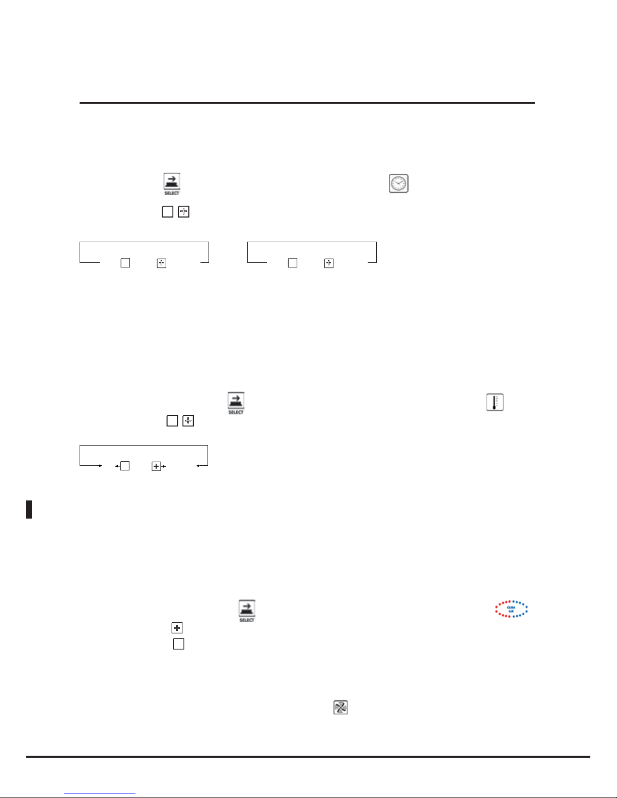
Italiano
18
Cottura con impostazione tempo e temperatura camera
Prima fase:
Premere il pulsante
finchè non lampeggerà il quadrante dell’orologio ;
Utilizzare i pulsanti
-
+
-
per impostare il tempo desiderato.
-
+
1° STEP
INF
INF
9h 59’
-
+
2° 3° 4°... STEP
HLD
HLD
0h 00’
9h 59’
0h 00’
N.B
Nella fase di cottura 1 è possibile impostare un tempo infinito “INF”, in questo caso il forno manterrà all’infinito i parametri temperatura e umidità impostati e dovrà essere fermato manualmente dall’utente. Nelle fasi
di cottura 2/3/4 è possibile impostare la funzione “HLD” per mantenere una temperatura costante in camera
di 70°C finchè il forno non verrà spento manualmente, questo per permettere di manenere il cibo infornato
caldo e pronto per essere servito.
Seconda fase:
Premere nuovamente il pulsante
finchè non lampeggerà il quadrante della temperatura ;
Utilizzare i pulsanti
-
+
-
per impostare la temperatura in camera desiderata.
-
+
PAU
0° C
260° C
N.B
In ogni fase è possibile selezionare la funzione pausa “PAU”. Il forno rimane in “Stand By” per il tempo
selezionato, con ventole e resistenze ferme e bruciatore spento. Impostazione utile in molte cotture
dove si vuole contenere la “Pressione Termica” sul prodotto .
Terza fase:
Eventuale CLIMA LUX con percentuale di estrazione umidità (DRY.Maxi™) o percentuale di immissione
vapore (STEAM.Maxi™):
• Premere nuovamente il pulsante
finchè non lampeggerà il quadrante del CLIMA LUX ;
• Utilizzare il pulsante
+
per impostare l’eventuale percentuale di
umidità
(STEAM.Maxi™) desiderata;
•
Utilizzare il pulsante - per impostare l’eventuale percentuale di estrazione umidità (DRY.Maxi™) desiderata;
• Lasciare su Ø per una cottura a pura convezione, senza né immettere né estrarre umidità.
Quarta fase:
Per cambiare la velocità dei flussi d’aria premere il tasto
;
la velocità attiva è visualizzata sul display 4.
Impostazione cotture
Page 75
Italiano
BakerTop
™
ChefTop
™
19
Cottura con sonda al cuore e temperatura camera impostata
Prima fase:
Premere il pulsante
finchè non lampeggerà il simbolo della temperatura.al cuore ;
Utilizzare i pulsanti
-
+
-
per impostare la temperatura al cuore desiderata.
-
+
0° C
120° C
N.B
Impostando la temperatura al cuore del prodotto, il tempo di cottura è automatico.
Una volta raggiunta la temperatura al cuore desiderata, il forno passa alla fase successiva, se impostata,
o termina il ciclo di cottura.
Seconda fase:
Premere nuovamente il pulsante finchè non lampeggerà il quadrante della temperatura ;
Utilizzare i pulsanti
-
+
-
per impostare la temperatura al cuore desiderata.
-
+
PAU
0° C
260° C
N.B
In ogni fase è possibile selezionare la funzione pausa “PAU”. Il forno rimane in “Stand By” per il tempo
selezionato, con ventole e resistenze ferme e bruciatore spento. Impostazione utile in molte cotture
dove si vuole contenere la “Pressione Termica” sul prodotto .
Terza fase:
Eventuale CLIMA LUX con percentuale di estrazione umidità (DRY.Maxi™) o percentuale di immissione
vapore (STEAM.Maxi™):
• Premere nuovamente il pulsante
finchè non lampeggerà il quadrante del CLIMA LUX
;
• Utilizzare il pulsante
+
per impostare l’eventuale percentuale di
umidità
(STEAM.Maxi™) desiderata;
•
Utilizzare il pulsante - per impostare l’eventuale percentuale di estrazione umidità (DRY.Maxi™) desiderata;
• Lasciare su Ø per una cottura a pura convezione, senza né immettere né estrarre umidità.
Quarta fase:
Per cambiare la velocità dei flussi d’aria premere il tasto
;
la velocità attiva è visualizzata sul display 4.
Impostazione cotture
Page 76

Italiano
20
Cottura con sonda al cuore e Delta T impostato
Prima fase:
Premere il pulsante
finchè non lampeggerà il quadrante della temperatura.al cuore
;
Utilizzare i pulsanti
-
+
-
per impostare la temperatura al cuore desiderata.
-
+
0° C
120° C
N.B
Impostando la temperatura al cuore del prodotto, il tempo di cottura è automatico.
Una volta raggiunta la temperatura al cuore desiderata, il forno passa alla fase successiva, se impostata,
o termina il ciclo di cottura.
Seconda fase:
Premere nuovamente il pulsante
finchè non lampeggerà il quadrante del Delta T ;
Utilizzare i pulsanti
-
+
-
per impostare il Delta T desiderato.
-
0° C
260° C
+
N.B
In ogni caso il forno non lavorerà mai a temperature maggiori di 260 °C
Terza fase:
Eventuale CLIMA LUX con percentuale di estrazione umidità (DRY.Maxi™) o percentuale di immissione
vapore (STEAM.Maxi™):
• Premere nuovamente il pulsante
finchè non lampeggerà il quadrante del CLIMA LUX
;
• Utilizzare il pulsante
+
per impostare l’eventuale percentuale di umidità (STEAM.Maxi™) desiderata;
• Utilizzare il pulsante - per impostare l’eventuale percentuale di estrazione umidità (DRY.Maxi™) desiderata;
• Lasciare su Ø per una cottura a pura convezione, senza né immettere né estrarre umidità.
Quarta fase:
Per cambiare la velocità dei flussi d’aria premere il tasto
;
la velocità attiva è visualizzata sul display 4.
Impostazione cotture
Page 77
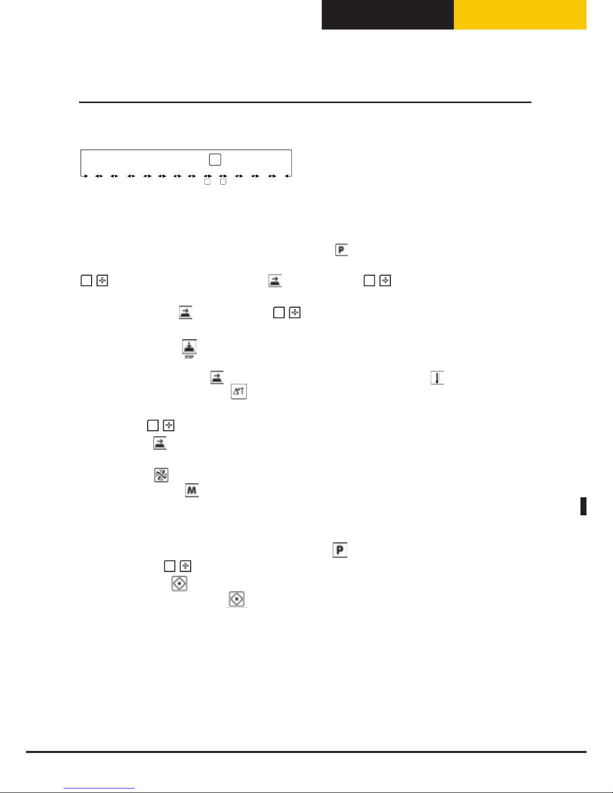
Italiano
BakerTop
™
ChefTop
™
21
Funzionamento con programmi
Il controllo elettronico ChefTouch/ BakerTouch permette all’utente di memorizzare fino a 99
programmi di cottura e assegnare loro un nome fino a 25 lettere.
Accedere al menù di programmazione premendo il tasto
;
Selezionare la posizione in cui si desidera memorizzare il programma (da P01 a P99) utilizzando i tasti
-
+
-
visualizzato sul display 5; Premere
e utilizzare i tasti
-
+
-
per selezionare la 1° lettera del
nome desiderato;
Premere nuovamente
e utilizzare i tasti
-
+
-
per selezionare la 2° lettera;
Ripetere la stessa operazione per le lettere successive;
Premere infine il tasto
per selezionare la temperatura di preriscaldamento del forno; comparirà la
scritta “PRE”;
Selezionare attraverso il tasto
se si vuole impostare una temperatura assoluta
di preriscaldamento
o una differenza di temperatura
fra la temperatura di preriscaldamento e quella del 1° Step di
cottura del programma;
Impostare con
-
+
-
il valore desiderato espresso in gradi;
Premere il tasto
e impostare quindi i parametri di funzionamento desiderati (Tempo, Temperatura al
Cuore, Temperatura Camera, Delta T, Clima) che compongono il programma;
Premere il tasto
e impostare il parametro di velocità di flusso d’aria nella camera di cottura;
Tenere premuto il tasto
per 5 secondi per memorizzare il programma (al termine dei 5 secondi viene
emesso un suono di conferma).
Utilizzare i programmi memorizzati dall’utente:
Accedere al menù di programmazione premendo il tasto
;
Premere i pulsanti
-
+
-
finchè non comparirà sul display 5 il numero del programma desiderato;
Premere il pulsante
per far partire il programma selezionato;
Premere nuovamente il pulsante
se si desidera interrompere l’esecuzione del programma.
N.B
Quando viene avviato un programma di cottura memorizzato, il forno esegue in automatico la fase di
preriscaldamento.
Quando viene avviato un programma di cottura il forno esegue il pre riscaldamento impostato. Durante
questa fase tutti i led e i display restano spenti eccetto il led “START / STOP” , il display 2 che visualizza
la scritta “PRE” e il display 4 indicante il programma che si sta utilizzando. Quando viene raggiunta la
temperatura desiderata tale temperatura viene mantenuta, il forno comincia ad emettere un segnale acustico
e sui display appaiono i dati relativi al primo step di cottura. Dopo aver aperto la porta del forno, inserito il
prodotto e chiuso la porta comincia automaticamente l’esecuzione del programma di cottura.
Programmazione da parte dell'utente
SHORT WASHING
LH2O WASHING
COOL
SEMI-AUTO WASHING
RESTART
LAST P
P01
P02
...
P99
MED WASHING
LONG WASHING
PUMP LOADING
P
- +
Page 78
Italiano
22
Funzione LASTP
Permette di selezionare in modo rapido l’ultimo ciclo di cottura eseguito, sia che esso sia stato lanciato
in modalità manuale sia che sia stato lanciato in modalità programmata.
Al termine del ciclo di cottura eseguito, premendo il pulsante
g
g
sul display 5 compare la scritta LASTP;
Premendo il pulsante
si farà ripartire l’ultimo ciclo di cottura eseguito.
Programmi lavaggio automatici
L’utilizzo del sistema di lavaggio Rotor.KLEAN™ codice XC405 permette di eseguire la pulizia
automatica della camera di cottura. I programmi di lavaggio automatici sono utilizzabili solo nel caso in
cui l’apparecchio sia dotato di tale opzione. Il sistema di lavaggio Rotor.KLEAN™ è installabile anche
dopo la messa in funzione dell’apparecchio.
All’interno della scheda di controllo sono memorizzati 3 programmi di lavaggio automatici (SHORT
WASHING breve, MED WASHING medio, LONG WASHING lungo) e un programma di pre carico dei
tubi di detersivo e brillantante (PUMP LOADING).
Esistono due ulteriori programmi di lavaggio semi-automatici: “LH2O” che permette di sciacquare e
successivamente asciugare portando la camera di cottura a 120°C senza l’utilizzo dei prodotti chimici e
“SEMI-AUTO WASHING” che permette un lavaggio del forno a temperatura pre-impostata con l'utilizzo
manuale di prodotti chimici.
Accedere al menù di programmazione premendo il tasto
;
Premere i pulsanti
-
+
-
finchè non comparirà sul display 5 i programmi di lavaggi LH2O, SEMI-AUTO
WASHING, SHORT WASHING, MED WASHING, LONG WASHING o PUMP LOADING;
Premere il pulsante
per far partire il programma selezionato;
N.B
Al primo utilizzo del sistema di lavaggio è consigliabile far partire il programma PUMP LOADING per rimuovere l’aria
all’interno dei tubi di detersivo e brillantante per non compromettere la qualità del lavaggio.
Tale programmi sono utilizzati solamente se installato il sistema di lavaggio Rotor.KLEAN™ (XC405).
Attenzione!
Non aprire mai la porta della camera di cottura nel corso di un processo di pulizia - possibile fuoriuscita di sostanze
chimiche usate per la pulizia ed esalazioni calde - pericolo di corrosione e scottature!Al termine della pulizia consistema
di lavaggio Rotor.KLEAN™, controllare che nella camera di cottura (anche dietro il lamierino di conduzione dell’aria) non
siano presenti residui di detersivo. Rimuovere eventuali residui e sciacquare accuratamente l’intera camera di cottura
(anche dietro il lamierino di conduzione dell’aria) con la doccia manuale – pericolo di corrosione!
Funzionalitá di serie
Attenzione!
E’ consigliabile pulire quotidianamente la camera di cottura per mantenere livelli di igienicità adeguati e per
evitare che l’acciaio inossidabile all’interno della camera di cottura si rovini. A tal proposito si consiglia l’utilizzo
del sistema di lavaggio Rotor.KLEAN™ codice XC405 che permette di eseguire la pulizia automatica della camera
di cottura. Attenzione!
Se l’apparecchio non viene pulito o non viene sottoposto ad una pulizia sufficiente, è possibile che i grassi o i
resti alimentari accumulati nella camera di cottura prendano fuoco – pericolo d’incendio!
Per evitare fenomeni di corrosione nella camera di cottura, l’apparecchio deve essere pulito tutti i giorni anche
se usato esclusivamente con calore umido (vapore).
Utilizzare solo detergenti raccomandati dal produttore dell’apparecchio. I detergenti di altri produttori possono
arrecare danni e, di conseguenza, causare la perdita del diritto di garanzia.
Page 79

Italiano
BakerTop
™
ChefTop
™
Programma raffreddamento camera cottura “COOL”
Il programma di raffreddamento camera cottura “COOL” permette di raffreddare la camera di cottura
facendo funzionare le ventole. Si può fare partire il programma anche con la porta aperta per accelerare
il raffreddamento della camera. Durante tale programma viene visualizzata la temperatura all’interno
della camera di cottura.
• Accedere al menù di programmazione premendo il tasto
;
• Premere i pulsanti
-
+
-
finchè non comparirà sul display 5 il programmi LCOOL;
• Premere il pulsante
per far partire il programma selezionato;
23
Funzionalitá di serie
Page 80

Italiano
24
Funzione ADAPTIVE.Clima
Attraverso la tecnologia ADAPTIVE.Clima, i forni ChefTop™ e BakerTop™ monitorano in modo costante
tutti i parametri di cottura, non solo la temperatura ma anche la reale umidità presente in camera, e
permettono all’utente di ottenere ad ogni infornata il risultato desiderato con la garanzia di una cottura
sempre perfetta indipendentemente dal numero di teglie infornate.
La quantità di vapore immessa in camera di cottura varia, a parità di programma, a seconda della quantità
di prodotto che viene introdotto nell’apparecchio. In linea generale, tanto maggiore è la quantità di
prodotto infornata tanto minore sarà la quantità di vapore prodotta dal forno.
Attraverso la tecnologia ADAPTIVE.Clima è inoltre possibile memorizzare l’ultimo processo di cottura
che è stato realizzato. Per questo utilizzo è consigliato l'uso abbinato con sonda al cuore MULTI.Point al
fine di evitare possibili pisizionamenti errati. Il controllo costante di tutti i parametri di cottura consente
infatti ai forni ChefTop™ e BakerTop™ di acquisire in modo accurato l’andamento della temperatura
e dell’umidità durante l’intero processo di cottura, rilevando anche gli effetti di eventuali interventi
manuali da parte dell’utente come per esempio l’apertura della porta.
Ottenuto il risultato desiderato la tecnologia ADAPTIVE.Clima consente all’utente di memorizzare il
processo effettivamente avvenuto e di ripeterlo infinite volte, con la certezza di un risultato sempre
identico e senza alcuna supervisione o intervento da parte dell’utente.
Il forno riprodurrà in modo automatico gli effetti delle azioni fatte dall’utente nel corso del processo
“pilota” (quello che si vuole venga ripetuto): se, per esempio, al 3° minuto di funzionamento l’apertura
della porta ha causato un abbassamento della temperatura di 20°C e l’eliminazione dell’umidità presente in
camera, il forno provvederà a simularne gli effetti anche nei processi di cottura realizzati successivamente.
Attenzione! Per memorizzare correttamente un programma ADAPTIVE.Clima è necessario che nel
processo di cottura “pilota” sia stata inserita correttamente la sonda al cuore, anche nel caso in cui il
programma impostato sul pannello comandi non ne preveda l’utilizzo.
Per memorizzare il processo di cottura appena realizzato attraverso la tecnologia ADAPTIVE.Clima è
necessario seguire la seguente procedura:
• al termine della cottura, premere il tasto
• con il tasto + Selezionare il programma di memoria su cui si vuole memorizzare il processo di cottura
“pilota”. Ad esempio ACM01, ACM02, …ACM20.
• premere
e utilizzare i tasti
-
+
-
per selezionare la 1° lettera del nome desiderato;
• premere nuovamente
e utilizzare i tasti
-
+
-
per selezionare la 2° lettera; ripetere la stessa
operazione per le lettere successive;
• completato l’inserimento del nome premere il pulsante
;
• tenere premuto il tasto
per 5 secondi per memorizzare il programma (al termine dei 5 secondi
viene emesso un suono di conferma).
Attenzione! Non è possibile modificare alcun parametro del programma ADAPTIVE.Clima memorizzato.
Per richiamare un programma ADAPTIVE.Clima procedere come segue:
• premere il pulsante
;
• selezionare il programma ADAPTIVE.Clima desiderato tramite i pulsanti
-
+
-
;
• far partire il programma tramite il pulsante
.
Funzionalitá di serie
Page 81

Italiano
BakerTop
™
ChefTop
™
25
Cotture automatiche ChefUnox - BakerUnox
Il controllo digitale ChefTouch - BakerTouch contiene nella propria memoria una serie di cotture
automatiche proposte da ChefUnox - BakerUnox.
Basta selezionare il tipo di cottura desiderato per poter cucinare, in automatico, un’infinita gamma di alimenti.
All’interno di ogni tipo di cottura automatica si ha infatti la possibilità di personalizzare alcuni parametri per
raggiungere, in base alle proprie esigenze personali, il grado di doratura ed il grado di cottura ritenute ottimali.
• Premere il tasto
;
• Utilizzare il tasto
-
per selezionare il programma desiderato;
• Premere il tasto
per far partire il programma;
• Premere nuovamente il tasto
se si vuole interrompere l’esecuzione del programma.
N.B
Prima di avviare il programma è possibile cambiare il valore di un parametro che permette di modificare
il grado di cottura desiderato. In funzione di questo il forno adeguerà la cottura per garantire un risultato
perfetto.
• Premere il tasto
finchè non lampeggerà il parametro che si desidera modificare;
• Utilizzare i tasti
-
+
-
per impostare il nuovo valore desiderato.
Nel caso si voglia rendere permanente la modifica effettuata:
• Premere il tasto
per 5 secondi (l’avvenuta memorizzazione e’ confermata da un segnale acustico).
CARATTERISTICA
PARAMETRO
MODIFICABILE
QUANDO
INCREMENTARE
QUANDO DIMINUIRE
ROASTING Cotture di arrosti Sonda al cuore 54°C Aumentare il grado di cottura Diminuire il grado di cottura
CRISPY ROAST Cotture di arrosti con crosta Sonda al cuore 54°C Aumentare il grado di cottura Diminuire il grado di cottura
NIGHT ROAST
Cottura di arrosti durante la notte
Sonda al cuore 54°C Aumentare il grado di cottura Diminuire il grado di cottura
BRAISE Carni stufate e in umido Tempo di cottura 1h Aumentare il grado di cottura Diminuire il grado di cottura
GRILL Verdure e carni alla griglia
9 Timer settabili, utilizzare
FAKIRO Grill
--
MULTI TIME
Cottura simultanea di +
prodotti con tempi diversi
tra loro.
Settare temperatura e
CLIMALUX, premere start
e utilizzare il tasto step per
impostare i 9 timer
--
POLLO
Cotture di polli , volatili,
pollame, selvaggina
Tempo 5 min Aumentare la doratura esterna Diminuire la doratura esterna
ROAST PATATO Patate al forno Tempo 5 min Aumentare la doratura esterna Diminuire la doratura esterna
BAKING
Cottura di prodotti da forno
congelati
Tempo 5 min Aumentare il grado di cottura Diminuire il grado di cottura
+3 REGEN Rigenerazione da 3°C Sonda al cuore 65°C
Aumentare la temperatura
del piatto per il servizio
Diminuire la temperatura
del piatto per il servizio
Processi di cottura pre-impostati
Page 82

Italiano
26
Tecnologia MAXI.Link:
comando di piu’ apparecchi con lo stesso pannello di controllo
Il pannello di controllo digitale ChefTouch – BakerTouch permette di comandare tutte le attrezzature UNOX
della linea ChefTop™ – BakerTop™ associate al forno. La tecnologia MAXI.Link consente inoltre di gestire, con
un unico controllo digitale, più forni. Il forno che si decide di utilizzare per comandare tutti gli altri apparecchi
diventa il forno MASTER. I forni comandati dal forno MASTER diventano forni SLAVE con controllo digitale
inattivo. I controlli digitali MASTER ed i controlli digitali SLAVE sono, all’occorrenza, intercambiali.
La selezione dell’apparecchio da controllare viene fatta mediante il tasto
e l’apparecchio controllato è
visualizzato dal display 6.
Tabella corrispondenza numero / apparecchio
ChefTop™
Numero apparecchio Codice apparecchio Dispositivo
1 Forno ChefTop™ master
2 Forno ChefTop™ slave 1
3 Forno ChefTop™ slave 2
4 Forno ChefTop™ slave 3
5 XK305 Abbattitore temperatura
6 XVL575 - XVL375 Mantenitore/ Forno cottura lenta
7 XC235 Sistema osmosi inversa
9 XC236 Kit OVEX.Net 2.0
BakerTop™
Numero apparecchio Codice apparecchio Dispositivo
1 Forno BakerTop™ master
2 Forno BakerTop™ slave 1
3 Forno BakerTop™ slave 2
4 Forno BakerTop™ slave 3
6 XL405 Lievitatore
7 XC235 Sistema osmosi inversa
9 XC236 Kit OVEX.Net 2.0
Tecnologia MAXI.Link
Page 83

Italiano
BakerTop
™
ChefTop
™
27
Consigli dello Chef per cotture uniformi
Preriscaldamento
E’ consigliabile sempre preriscaldare il forno ad una temperatura superiore a quella prevista per la cottura
di almeno 30-50°C per annullare gli effetti di perdita di calore dovuta all’apertura della porta.
E’ possibile preriscaldare il forno a 300 °C.
Non tenere il forno a temperature maggiori di 260 °C per più di 10 minuti.
Tipologia di teglie
Per ottenere una perfetta qualità di cottura ed una rosolatura uniforme del prodotto è consigliabile non
utilizzare contenitori troppo alti perché impedirebbero una corretta circolazione dell’aria.
Spazio tra le teglie
Per una cottura uniforme è indispensabile controllare che ci siano almeno 3 cm di spazio tra il prodotto
completamente lievitato e la teglia superiore.
Carico di cottura
Per ottenere i migliori risultati è necessario non sovraccaricare il forno e controllare, in caso di pane e
prodotti di pasticceria, l’orientamento del prodotto sulle teglie rispetto al flusso dell’aria.
Posizionamento della sonda al cuore
Per un corretto funzionamento della sonda al cuore è indispensabile inserirla, dall’alto verso il basso, nel
punto più spesso dell’alimento fino a raggiungerne il centro con la punta della sonda.
Nel caso di alimenti con spessore ridotto, la sonda va inserita orizzontalmente al piano di appoggio.
Attenzione all’apertura della porta!!!
Il calore ed il vapore potrebbero provocare scottature.
Principi di cottura
Page 84
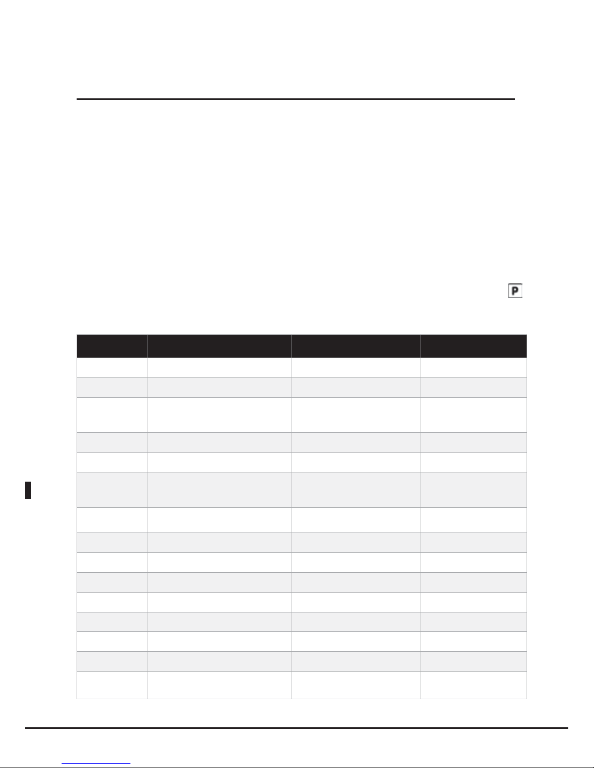
Italiano
Il pannello di controllo digitale dei forni ChefTop™ - BakerTop™ è stato predisposto per far dialogare facilmente il forno con
il mondo esterno attraverso sistemi di comunicazione presenti e futuri: USB, Bluetooth, seriale ecc.
E’ disponibile il kit interfaccia USB XC236 che permette di svolgere le seguenti funzioni:
• inserimento programmi di cottura
• modifica parametri operativi (es. taratura sonde)
• diagnostica malfunzionamenti
• memorizzazione dell’andamento delle temperature all’interno della camera del forno o della camera dell’abbattitore (dati
necessari per il sistema HACCP)
Ulteriori informazioni sono presenti all’interno del kit.
Messaggi di warning (attenzione):
Quando viene identificata una situazione di malfunzionamento che tuttavia, pur con funzionalità limitate, consente il
funzionamento dell’apparecchiatura viene visualizzato un messaggio di attenzione (WARNING).
Il dispositivo continua a funzionare e la modalità visualizzazione WARNING permane fino a quando non viene premuto il pulsante
.
Messaggi di warning del forno:
Visualizzazione
display
Descrizione Effetto Risoluzione problema
WF01
E’ stato rilevato un errore sui dati letti dalla sonda
camera 1
Il forno continua a funzionare utilizzando i soli
dati rilevati dalla sonda camera 2.
Contattare il servizio assistenza clienti
WF02
E’ stato rilevato un errore sui dati letti dalla sonda
camera 2
Il forno continua a funzionare utilizzando i soli
dati rilevati dalla sonda camera 1.
Contattare il servizio assistenza clienti
WF03
E’ stato rilevato un errore sui dati letti dalla sonda al
cuore
Non è possibile impostare step o far partire
programmi che utilizzano la sonda al cuore; se
è in esecuzione uno step che utilizza la sonda al
cuore si passa allo step successivo
Contattare il servizio assistenza clienti
WF04
E’ stato misurato un regime di rotazione delle ventole
con corretto
Disattivate le funzionalità frenata motore Contattare il servizio assistenza clienti
WF05
E’ stato rilevato un errore sul sistema di raffreddamento
dei componenti elettronici
Possibile non funzionamento della ventola di
raffreddamento dei componenti elettronici
Contattare il servizio assistenza clienti
WF06
E’ stata misurata una temperatura eccessiva sulla
scheda di potenza del forno
Esiste il rischio di danneggiare in modo
permanente la scheda di potenza
Verificare che siano state rispettate le
norme di posizionamento previste dal
manuale di installazione. Contattare il
servizio assistenza clienti
WF08
E’ stata rilevata la presenza della scheda gas ma il
forno è settato come elettrico
Il forno continua a funzionare però viene gestito
come un forno elettrico
Contattare il servizio assistenza clienti
WF09
E’ stato rilevato un errore sulla frenata motore
Il forno continua a funzionare ma non viene più
effettuata la frenata
Contattare il servizio assistenza clienti
WF10
E’ stato rilevato un errore in un parametro non
indispensabili della scheda di potenza
Il forno continua a funzionare (con alcuni limiti
in base al parametro corrotto)
Contattare il servizio assistenza clienti
WF11
E’ stata misurata una temperatura non corretta nella
scheda gas
Il forno continua a funzionare Contattare il servizio assistenza clienti
WF12
E’ stata misurata una temperatura eccessiva sulla
scheda termocoppie esterne
Il forno continua a funzionare Contattare il servizio assistenza clienti
WF13
E’ stato rilevato un errore sui dati letti dalla sonda
sottovuoto esterna
Il forno continua a funzionare però non è
possibile utilizzare la sonda sottovuoto esterna
Contattare il servizio assistenza clienti
WF14
E’ stato rilevato un errore sui dati letti dalla sonda al
cuore multipunto (totalmente non funzionante)
Il forno continua a funzionare però non è più
possibile eseguire cotture con la sonda al cuore
Contattare il servizio assistenza clienti
WF15
E’ stato rilevato un errore sul sistema di comunicazione
scheda termocoppie
Il forno continua a funzionare però non è
possibile utilizzare la sonda sottovuoto esterna
Contattare il servizio assistenza clienti
WF17
E’ stato rilevato un errore sui dati letti dalla sonda al
cuore multipunto (parzialmente non funzionante)
Il forno continua a funzionare però la misurazione
della temperatura al cuore potrebbe essere
imprecisa
Contattare il servizio assistenza clienti
28
Comunicazione forno-utente
Page 85
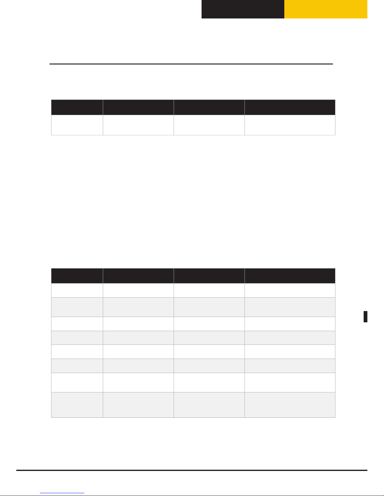
Italiano
BakerTop
™
ChefTop
™
Messaggi di warning (attenzione) scheda controllo:
Visualizzazione
display
Descrizione Effetto Risoluzione problema
WD10
E’ stato rilevato un errore in un
parametro non indispensabili della
scheda controllo
Il forno continua a funzionare (con
alcuni limiti in base al parametro
corrotto)
Contattare il servizio assistenza clienti
Messaggi di allarm (allarme):
Quando viene identificata una condizione che impedisce qualsiasi funzionamento dell’apparecchio viene
visualizzato un segnale di ALLARME (ALLARM) e l’apparecchio stesso deve quindi essere messo in stato di STOP.
Il dispositivo si ferma e permane sul display del forno la modalità visualizzazione ALLARM! finché il problema
non sia risolto. Se il dispositivo si trova in stato di funzionamento nel momento in cui viene rilevato lo stato di
ALLARME, esso si blocca e viene visualizzato il segnale relativo al problema diagnosticato.
Per la risoluzione di un problema è necessario contattare un centro assistenza autorizzato.
Una volta risolto il problema è possibile riattivare l’apparecchio premendo il pulsante ”START/STOP”.
Se presenti altri dispositivi/accessori collegati al forno questi continuano a funzionare normalmente almeno
che l’allarme sia rispetto ad uno specifico dispositivo che impedisce la continuità di suo funzionamento.
Messaggi di allarme del forno:
Visualizzazione
display
Descrizione Effetto Risoluzione problema
AF01
E’ stato rilevato un
surriscaldamento dei motori
Forno bloccato Contattare il servizio assistenza clienti
AF02
E’ stato rilevato un
surriscaldamento del termostato
sicurezza
Forno bloccato Contattare il servizio assistenza clienti
AF03
E’ stato rilevato un errore sui dati
letti da entrambe le sonde camera
Forno bloccato Contattare il servizio assistenza clienti
AF04
Comunicazione tra scheda di
controllo e potenza interrotta
Forno bloccato Contattare il servizio assistenza clienti
AF05
Comunicazione tra scheda gas e
potenza interrotta
Forno bloccato Contattare il servizio assistenza clienti
AF06
E’ stata misurata una temperatura
eccessiva dei fumi forno a gas
Forno bloccato Contattare il servizio assistenza clienti
AF10
E’ stato rilevato un errore in un
parametro indispensabili della
scheda potenza
Forno bloccato Contattare il servizio assistenza clienti
GAS
Non è rilevata la presenza di
fiamma nel bruciatore
Il bruciatore viene disattivato. E’
possibile effettuare un ulteriore
tentativo di accensione premendo
il tasto START/STOP.
In caso di non riuscire a riaccendere il forno
chiudere immediatamente il rubinetto del
gas e contattare il servizio assistenza clienti
N.B.
Ogni volta che il forno viene avviato elettricamente e ogni volta che la scheda di controllo esce dallo stato
di STAND BY viene fatta una scansione della scheda di controllo (con relativa visualizzazione se presenti)
degli ALLARMI / WARNING.
Comunicazione forno-utente
29
Page 86

Italiano
Messaggi di allarm (allarme) scheda controllo:
Visualizzazione
display
Descrizione Effetto Risoluzione problema
AD01
E’ stato rilevato un errore nella memoria della
scheda controllo
Forno bloccato
Contattare il servizio assistenza
clienti
AD02
E’ stato rilevato un errore sulla tastiera Forno bloccato
Contattare il servizio assistenza
clienti
AD03
E’ stato rilevato un errore sul display Forno bloccato
Contattare il servizio assistenza
clienti
AD04
Comunicazione interrotta Forno bloccato
Contattare il servizio assistenza
clienti
AD10
E’ stato rilevato un errore in un parametro
indispensabili della scheda controllo
Forno bloccato
Contattare il servizio assistenza
clienti
Manutenzione in caso di guasto:
In caso di guasto disattivare l’apparecchiatura:
Scollegare l’apparecchiatura dall’alimentazione elettrica.
Per apparecchi a gas
Interrompere immediatamente l’alimentazione del gas.
Rivolgersi ad un centro di assistenza tecnica con personale addestrato.
Prima di telefonare al servizio di assistenza clienti:
Guasto Possibile causa Rimedio
Il forno è completamente spento Mancanza della tensione di rete
Verificare il collegamento alla rete
elettrica.
Non viene prodotto vapore nella
camera di cottura
Ingresso acqua chiuso Aprire ingresso acqua
Collegamento alla rete idrica o al
serbatoio eseguito in maniera non
corretta
Verificare il collegamento alla rete idrica o
al serbatoio
Assenza di acqua nel serbatoio (nel caso
di carico acqua dal serbatoio)
Immettere acqua nel serbatoio
Filtro entrata acqua ostruito impurità Pulire il filtro
Dopo aver impostato tempo o
temperatura al cuore e aver premuto il
tasto START / STOP il forno non parte
Porta aperta o chiusa in maniera errata Verificare la chiusura della porta
Con la porta chiusa fuoriesce acqua
dalla guarnizione
Guarnizione sporca Pulire la guarnizione con un panno umido
Guarnizione danneggiata
Rivolgersi ad un tecnico specializzato per
la riparazione
Meccanismo della maniglia allentato
Rivolgersi ad un tecnico specializzato per
la riparazione
Comunicazione forno-utente
30
Page 87

Italiano
BakerTop
™
ChefTop
™
Norme di sicurezza:
Tutte le operazioni di installazione, montaggio, assistenza e manutenzione devono essere eseguite da personale
qualificato secondo le norme in vigore.
Tale personale tecnico deve comunque essere informato e applicare le normative riguardanti la sicurezza dei
prodotti ripristinati, nonché la tutela della sicurezza sul posto di lavoro.
L’Installazione dell’apparecchio da parte di personale qualificato non autorizzato da UNOX comporta la
rinuncia ai diritti di garanzia.
In considerazione di quanto sopra UNOX è manlevato da ogni responsabilità che dovesse scaturire da interventi
non eseguiti a regola d’arte o da errate interpretazioni o applicazioni delle normative o del presente manuale.
Attenzione!
Installazione, assistenza, manutenzione o pulizia errati, nonché eventuali modifiche apportate agli apparecchi
possono provocare danni, lesioni o incidenti mortali.
Leggere attentamente le istruzioni di installazione prima di installare l‘apparecchio.
Questo apparecchio può essere utilizzato solo per la cottura di cibi nell’ambito di cucine industriali.
Qualsiasi altro impiego non è conforme all‘uso previsto e pertanto pericoloso.
Solo apparecchi a gas
Se l‘apparecchio è installato sotto una cappa di aspirazione, quest‘ultima deve essere accesa durante il
funzionamento dell‘apparecchio stesso – gas combusti!
Se l‘apparecchio è collegato ad un camino, il tubo di scarico deve essere pulito secondo quanto previsto dalle
disposizioni specifiche del paese – Pericolo d‘incendio! (Per informazioni in merito contattare il proprio installatore.)
Non collocare alcun oggetto sul tubo dei gas di scarico dell‘apparecchio – Pericolo d‘incendio!
La zona sotto l‘apparecchio non deve essere bloccata o intralciata da oggetti – Pericolo d‘incendio!
L‘apparecchio può essere fatto funzionare solo in un ambiente senza vento – Pericolo d‘incendio!
Comportamento in caso di odore di gas:
Interrompere immediatamente l‘alimentazione del gas;
Non toccare alcun interruttore elettrico;
Aerare bene l‘ambiente;
Evitare di produrre fiamme libere e scintille;
Usare un telefono esterno ed informare subito l‘azienda del gas;
------
Leggere attentamente il manuale prima dell’installazione e della messa in funzione dell’apparecchio.
Controllare che l’apparecchio non sia stato danneggiato durante il trasporto.
Se si sospetta che si sia verificato un danno durante il trasporto informare immediatamente il proprio
rivenditore autorizzato / lo spedizioniere.
Al momento di smaltire l’apparecchio usato, non conferirlo nei rifiuti ne nel container degli elettrodomestici
usati presso i punti di raccolta comunali.
UNOX aderisce al consorzio per Valere, consorzio nazionale recupero attrezzature professionali per l’ospitalità
ed è lieta di aiutarvi per il corretto smaltimento dell’apparecchio usato.
31
ISTRUZIONI PER L’INSTALLATORE
Page 88

Italiano
Verificare che l’unità passi da eventuali porte, corridoi o altri passaggi per arrivare al luogo di installazione.
Nella tabella si riportano gli ingombri dei modelli con e senza imballaggio:
MODELLI
Ingombro senza imballo
LxDxH mm
Ingombro con imballo
LxDxH mm
MODELLI
Ingombro senza imballo
LxDxH mm
Ingombro con imballo
LxDxH mm
ChefTop™ elettrici ChefTop™ gas
XVC 055 574x737x498 740x800x640 - - -
XVC 105/ 105P 750x782x498 880x880x640 - - -
XVC 205 574x758x632 740x800x780 - - -
XVC 305/ 305P 750x792x625 880x880x780 XVC 315G 750x796x840 870x870x1000
XVC 505/ 505P 750x792x813 880x880x970 XVC 515G 750x796x1028 870x870x1200
XVC 705/ 705P 750x792x960 880x880x1120 XVC 715G 750x796x1175 870x870x1400
XVC 1005P/ 905P 866x972x1866 980x1140x2000 XVC 1015G/ 915G 866x970x2072 980x1140x2250
XVC 1205 860x1160x888 990x990x1300 XVC 1215G 860x1160x1028 -
XVC 2005 860x1160x1208 980x1300x1310 XVC 2015G 860x1160x1348 -
XVC 4005P/ 3205P 869x1206x1857 985x130x2000 XVC 4015G/ 3215G 869x1206x2072 -
BakerTop™ elettrici BakerTop™ gas
XBC 405 860x900x624 980x1060x772 - - -
XBC 605 860x900x820 980x1060x960 XBC 615G 860x900x1028 950x1030x1180
XBC 805 860x900x1140 980x1060x1280 XBC 815G 860x900x1348 980x1060x1470
XBC 1005/ 905 866x972x1866 980x1140x2000 XBC 1015G/ 915G 866x970x2072 980x1140x2250
Il trasporto dell’apparecchio deve essere effettuato esclusivamente sul pallet fornito da UNOX.
Cautela!
Assicurarsi che, durante il trasporto, l‘apparecchio non possa rovesciarsi.
Tenere in considerazione il peso dell’apparecchio. Avvalersi di supporti.
Durante l’installazione, indossare le scarpe protettive.
32
Istruzioni per il trasporto dell'apparecchio
Page 89

Italiano
BakerTop
™
ChefTop
™
L’installazione di un forno è divisa in 5 fasi:
1) Operazioni preliminari e posizionamento
2) Collegamento elettrico / Collegamento gas
3) Collegamento idrico: acqua in ingresso
4) Collegamento idrico: acqua in uscita
5) Uscita Fumi
2
3
5
1
4
1. Posizionamento
2. Collegamento elettrico
3. Acqua in ingresso
4. Acqua in uscita
5. Uscita fumi
Operazioni preliminari e posizionamento
Luogo di installazione
Prima di posizionare l’apparecchio verificare le misure d’ingombro e l’esatta posizione dei collegamenti elettrici, idrici, scarico fumi secondo le figure riportate nell’allegato fascicolo “Dati Tecnici”.
Attenzione!
Non installare l’apparecchio in prossimità di materiali infiammabili.
Se l’apparecchio é posizionato vicino a pareti, divisori, mobili da cucina, bordure decorate ecc., è obbligatorio
che questi siano di materiale non infiammabile.
In caso contrario devono essere rivestiti con materiale isolante termico non infiammabile, e occorre prestare
la massima attenzione alle norme di prevenzione incendi.
33
Installazione dell’apparecchio
Page 90
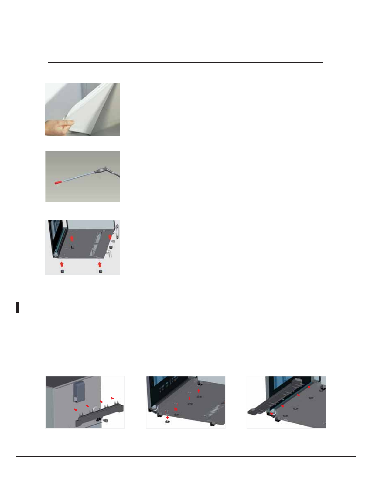
Italiano
Rimozione pellicole di protezione
Togliere completamente la pellicola protettiva dalle pareti esterne
dell’apparecchio con attenzione ed evitare che rimangano residui di colla. Se
nonostante ciò dovessero rimanervi ancora residui di colla toglierli con un
solvente appropriato.
Rimuovere la protezione siliconica del puntale
della sonda al cuore
Fissaggio piedini apparecchi da banco
I piedini che si trovano nella busta all’interno dell’imballo servono a garantire
il passaggio d’aria per il raffreddamento dei componenti elettronici e delle
pareti esterne del forno. E’ quindi fondamentale che essi vengano montati
correttamente. Inserire i piedini nelle posizioni indicati nell’immagine.
Attenzione! Non utilizzare il forno senza piedini poiché potrebbe causare
surriscaldamenti dei componenti elettronici e il loro danneggiamento
irreversibile.
Cassetto raccogli gocce
Il cassetto raccogli gocce che si trova fissato nella schiena del forno serve per raccogliere i liquidi che si
depositano sul vetro interno del forno evitando che questi cadano al suolo all’apertura della porta.
Rimuovere il cassetto raccogli-gocce dalla schiena del forno utilizzando un cacciavite, inserire le guide che si
trovano nella busta all’interno del forno nelle loro sedi e posizionare il cassetto come in figura.
34
Installazione dell’apparecchio
Page 91

Italiano
BakerTop
™
ChefTop
™
Avvertenze
Posizionare l’apparecchio in modo che la parete posteriore sia facilmente accessibile per effettuare
l’allacciamento elettrico e per consentire la manutenzione. L’apparecchio non è adatto all’incasso e
al posizionamento in batteria. E’ obbligatorio rispettare una distanza minima di 50 mm tutto attorno
all’apparecchio.
In caso di presenze di eventuali friggitrici o altri possibili sorgenti di schizzi di liquidi caldi, mantenere almeno
le distanze di 45 cm laterali e 70 cm dal retro del forno
450 mm
700 mm
50 mm
50 mm
Per motivi di sicurezza, gli apparecchi da tavolo devono essere posizionati soltanto su sottostrutture o sottoarmadi
del produttore dell‘apparecchio. L‘altezza di lavoro massima al livello del ripiano piu alto e di 1600 mm.
1600 mm
Gli adesivi per la vostra sicurezza
«altezza max. dell'ultimo ripiano per i
contenitori con liquidi» si trovano nello
starter kit.
Dopo aver installato l'apparecchio, applicare
l'adesivo ad un'altezza di 1.600 mm.
(vedi esempio)
In caso di forni da tavolo utilizzare gli appositi stand, lievitatore, porta-teglie, oppure posizionare il forno
sopra un tavolo in acciaio inox.
Non installare i forni direttamente sul pavimento.
35
Posizionamento
Page 92

Italiano
Allineare orizzontalmente l’apparecchio.
Verificare che l’apparecchio sia installato in piano.
Durante la cottura vengono prodotti fumi caldi ed altri odori che vengono evacuati dal camino; è quindi
consigliabile posizionare il forno sotto apposita cappa aspirante oppure utilizzare le apposite cappe UNOX
e provvedere al convogliamento verso l’esterno dei fumi in uscita.
36
Posizionamento
Page 93
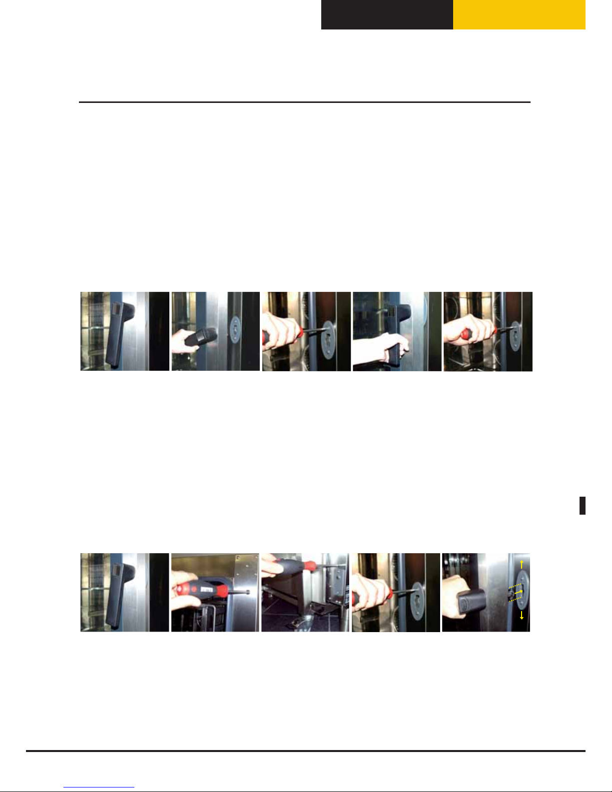
Italiano
BakerTop
™
ChefTop
™
Posizionamento
Regolazione chiusura porta
Modelli senza carrello
Nel caso in cui, una volta posizionato il forno la maniglia della porta non dovesse rimanere correttamente
chiusa (fig.1), probabilmente occorre adattare lo scrocco di chiusura; procedere come segue:
•con la porta del forno aperta (fig.2), allentare leggermente le viti di fissaggio dello scrocco (fig.3)
•richiudere la porta e girare la maniglia per bloccarne l’apertura(fig.4)
•se la porta rimane chiusa con la maniglia perfettamente in posizione verticale, riaprire la porta e fissare
energicamente le viti di fissaggio dello scrocco definitivamente (fig.5).
•se il problema continua a persistere ripetere la sequenza provando ad allentare maggiormente le viti di
fissaggio dello scrocco.
2 3 451
Modelli carrellati
Nel caso in cui, una volta posizionato il forno, la maniglia della porta del forno non dovesse chiudere
correttamente in posizione verticale (fig.1), probabilmente occorre adattare lo scrocco di chiusura e
procedere come segue:
•con la porta del forno aperta, allentare le viti superiore e inferiore di fissaggio dello scrocco (fig.2 e 3)
•allentare leggermente le 2 viti centrali di fissaggio dello scrocco (fig.4)
•avvicinare la maniglia e regolare la posizione dello scrocco in direzione verticale in modo che il perno di
chiusura risulti perfettamente allineato (fig.5)
•fissare le viti superiore, inferiore e centrali di fissaggio dello scrocco e provare a chiudere la porta
•se la porta rimane chiusa con la maniglia perfettamente in posizione verticale, riaprire la porta e bloccare
definitivamente la posizione delle viti dello scrocco fissandole energicamente
•se il problema persiste ripetere la sequenza provando ad allentare maggiormente le viti.
23451
N.B
Una superficie d’appoggio del forno non perfettamente piana, non permette alla maniglia della porta
di chiudersi perfettamente: se la deformazione del piano è lieve, si può ovviare al problema adattando
lo scrocco di chiusura applicando il metodo precedentemente descritto; non è possibile compensare il
problema in caso di forti deformazioni del piano o disuniformità della superficie d’appoggio del forno.
37
Page 94

Italiano
La superficie di appoggio deve essere piana e livellata. Il sito di installazione deve essere tale da sostenere il
peso dell’apparecchio e del massimo carico. Fare riferimento alla tabella qui riportata:
MODELLI Peso (scarico) MODELLI Peso (scarico)
ChefTop™ elettrici ChefTop™ gas
XVC 055 35 kg - -
XVC 105/ 105P 45 kg - -
XVC 205 41 kg - -
XVC 305/ 305P 59 kg XVC 315G 73 kg
XVC 505/ 505P 76 kg XVC 515G 90 kg
XVC 705/ 705P 83 kg XVC 715G 97 kg
XVC 1205 150 kg XVC 1215G 170 kg
XVC 2005 165 kg XVC 2015G 185 kg
BakerTop™ elettrici BakerTop™ gas
XBC 405 60 kg - -
XBC 605 86 kg XBC 615G 106 kg
XBC 805 118 kg XBC 815G 132 kg
Una volta posizionato l’apparecchio verificare che non possa scivolare o ribaltarsi.
Attenzione!
Se l'apparecchio viene montato su un sottotelaio o un sottoarmadio mobile, l'apparecchio medesimo dovrà
essere fissato con una catena o una fune supplementare che ne eviti lo scivolamento, per evitare danni alla
linea di alimentazione della corrente o del gas.
Posizionamento
38
Page 95

Italiano
BakerTop
™
ChefTop
™
Modelli carrellati
Operazione preliminare - Estrazione carrello
Il carrello viene posizionato all'interno del forno e fissato attraverso due viti laterali per renderlo sicuro
durante il trasporto. Prima di rimuovere il carrello svitare le due viti laterali come illustrato in figura:
Regolazione piedini per inserimento carrello
Per garantire il corretto posizionamento del carrello all'interno del forno è necessario controllare ed
eventualmente regolare l'altezza dei piedini. Uno dei due piedini frontali deve rimanere fisso per garantire
l'altezza di base già predisposta a 173 mm. In base al piedino frontale lasciato fisso gli altri tre possono
essere regolati di conseguenza. Vedi figura di esempio:
173 mm
-12
+12
Verificare che la lunghezza delle diagonali della bocca del forno sia
identica. Qualora non lo fosse agire sui piedini regolabili.
Attenzione!
Accertarsi che il carrello porta teglie si possa movimentare facilmente
e non ci sia alcun ostacolo al movimento di inserimento e di estrazione
dal forno: eventuali urti possono provocare la fuoriuscita di liquidi o
alimenti caldi e provocare ustioni.
39
Posizionamento
Page 96
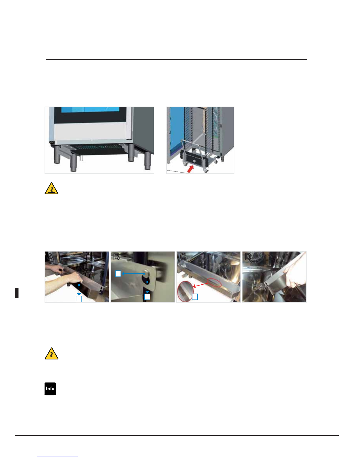
Italiano
Inserimento carrello e posizionamento paratia chiusura porta:
Per l’inserimento del carrello portateglie all’interno del forno infilarlo seguendo le guide fissate sotto il forno.
Attenzione!
Il carrello portateglie può essere caldo e deve essere toccato solo utilizzando adeguati indumenti termici
protettivi.
Nella parte inferiore centrale della facciata del forno è presente un micro porta; il forno si accende solamente se il
carrello è inserito all’interno della camera di cottura o nel caso di posizionamento della paratia chiusura porta.
Si consiglia di utilizzare la paratia nei processi di preriscaldamento o di lavaggi automatici.
Per il posizionamento della paratia al forno procedere come di seguito:
A B C D
1
3
2 4
- Con la porta aperta posizionare la paratia (1) appoggiando i fori (2) agli appositi perni (3) nella parte inferiore
del forno (Immagini A, B, C).
- Quando il cassetto raccogli gocce è pieno, svuotare il cassetto afferrandolo attraverso gli appositi impugnature
(4) sopra lo scarico posto sul fondo della camera di cottura del forno (Immagine D).
Attenzione!
La superficie posteriore del cassetto raccogli gocce può essere calda e deve essere toccata solo utilizzando
adeguati indumenti termici protettivi.
I carrelli della linea BakerTop non sono dotati di serie del vassoio raccogli gocce come della linea ChefTop.
Quindi per i processi di lavaggi si consiglia di utilizzare la paratia di chiusura porta che è dotata di un cassetto
per raccogliere i liquidi che si depositano sul vetro interno del forno.
40
Posizionamento
Page 97
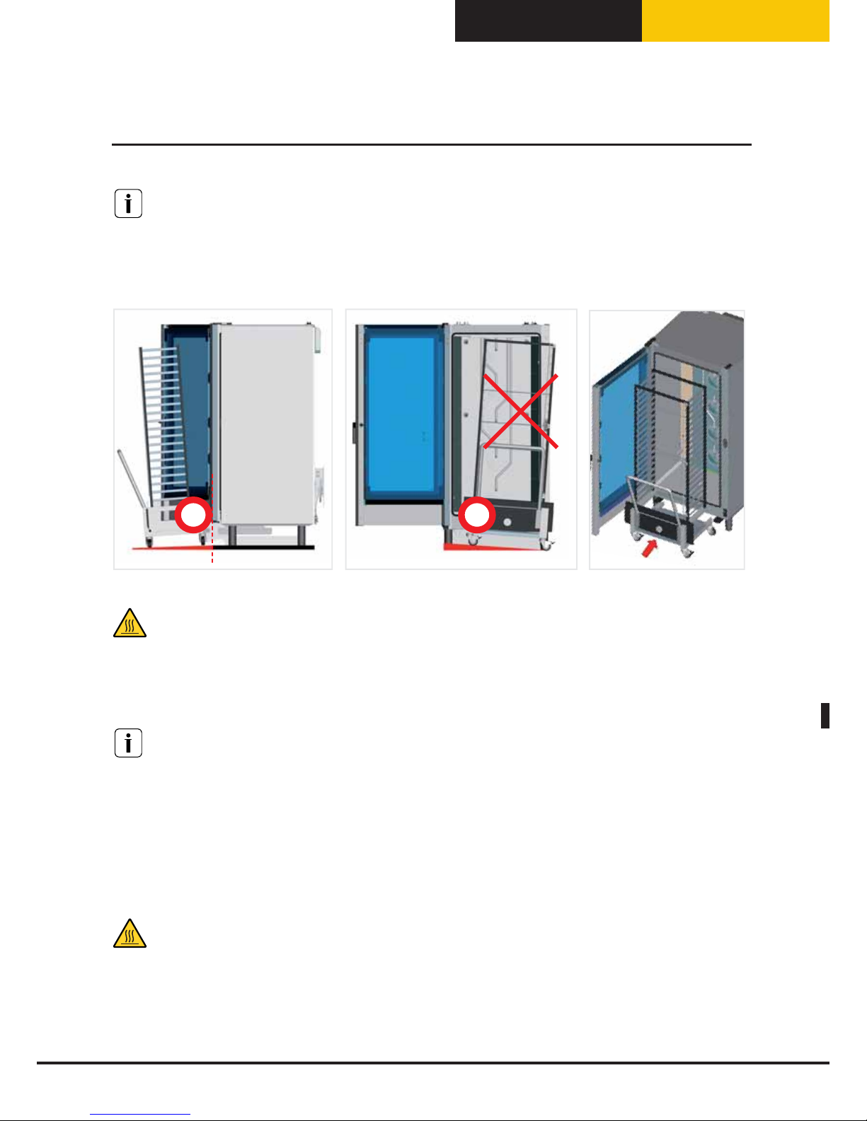
Italiano
BakerTop
™
ChefTop
™
Attenzione!
Se il pavimento non è piano, occorre renderlo tale con una rampa di ingresso la cui angolazione massima non
deve superare i quattro gradi.
Il forno deve essere installato su superficie piana.
Max.
4°
Max.
2°
Attenzione!
Se si supera l’angolo d’ingresso, è possibile che durante la fase di inserimento/estrezione del carrello i liquidi
di cottura caldi fuori escano dai contenitori.
Pericolo ustioni!
Attenzione!
Un carrello portateglie non posizionato correttamente può comportare un malfunzionamento
dell’apparecchio.
Quando caricato il la parte frontale del carrello può abbassarsi leggermente. Verificare che il carrello possa
entrare ed uscire agevolmente dal forno senza strisciare la superficie inferiore della camera di cottura. Nel
caso si verifichi quest’eventualità è necessario agire sui piedini dell’apparecchio e abbassarlo quanto necessario
per consentire la corretta movimentazione del carrello.
Attenzione!
Accertarsi che il carrello porta teglie si possa movimentare facilmente e non ci sia alcun ostacolo al movimento
di inserimento e di estrazione dal forno: eventuali urti possono provocare la fuoriuscita di liquidi o alimenti
caldi e provocare ustioni.
41
Posizionamento
Page 98

Italiano
Avvertenze
Il collegamento alla rete d’alimentazione elettrica deve essere effettuato secondo le normative vigenti.
L’apparecchio deve essere posto in modo che la spina di connessione alla rete sia accessibile (per gli apparecchi
dotati di spina Schuko).
Il dispositivo di sezionamento deve essere collegato a monte del collegamento dell’apparecchio in accordo con
le normative locali vigenti.
Si consiglia l’impiego di un interruttore di sicurezza per correnti di guasto.
La tensione di alimentazione, quando l’apparecchio è in funzione, non deve discostarsi dal valore della tensione
nominale, riportata sulla targhetta dati dell’apparecchio.
Attenzione!
I collegamenti elettrici devono essere realizzati da personale tecnico iscritto a gli enti previsti dalla legge per
l’esercizio della sua attività previsti dalla normativa del paese in cui l’apparecchio viene istallato. Tale personale
tecnico deve comunque essere informato e deve applicare le normative riguardanti la sicurezza dei prodotti
ripristinati, nonché la tutela della sicurezza sul posto di lavoro. In considerazione di quanto sopra riportato
UNOX è manlevato da ogni responsabilità che dovesse scaturire da interventi non eseguiti a regola d’arte o da
errate interpretazioni o applicazioni delle normative.
Attenzione!
Osservare il codice cromatico dei fili. Un collegamento errato può portare a scosse elettriche.
Un collegamento errato può danneggiare l‘apparecchio.
Codici colore fili:
Giallo/verde = conduttore di protezione
Blu = conduttore di neutro
Marrone, grigio o nero = fase L1, L2, L3
Per apparecchi con alimentazione a gas:
Attenzione!
Rispettare i poli del collegamento elettrico.
Se i poli sono invertiti, il bruciatore non funziona.
Attenzione!
Osservare sempre le normative e la legislazione locali.
42
Allacciamento elettrico
Page 99
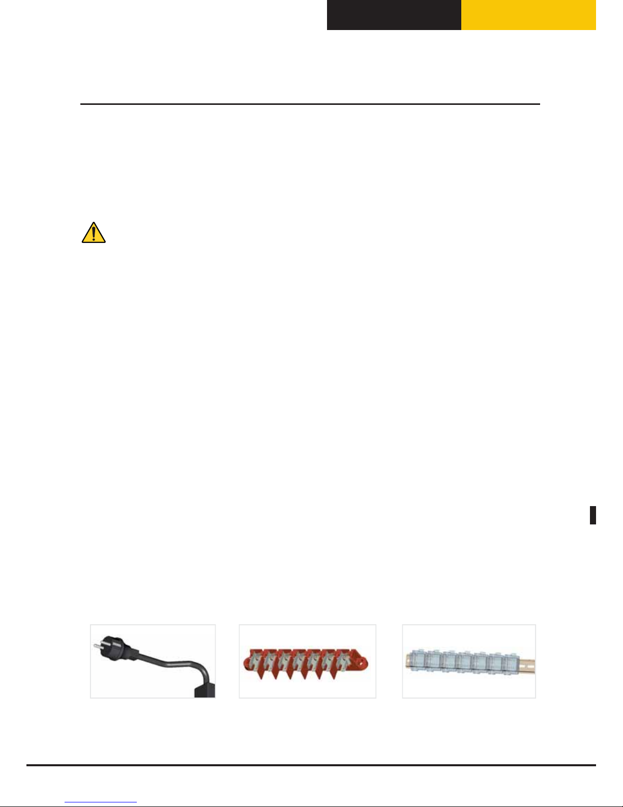
Italiano
BakerTop
™
ChefTop
™
Prima di connettere il forno alla rete elettrica, confrontare i dati relativi alla rete di alimentazione
dell’impianto con quelli richiesti dall’apparecchio, riportati nella targhetta applicata ad esso.
Nel caso le tensioni e le fasi di alimentazioni siano differenti, provvedere alla corretta cablatura delle fasi
rispettando i dati riportati sui fogli allegati. Verificare l’assenza di dispersione elettrica tra fasi e terra.
Verificare la continuità elettrica tra la carcassa esterna e il filo di terra della rete. Si consiglia di utilizzare un
multimetro digitale per effettuare queste operazioni.
Attenzione!
Verificare che tutte le connessioni elettriche siano ben serrate prima di connettere l’apparecchio alla rete
elettrica.
1. Forni dotati di cavo e spina Schuko (monofase): è sufficiente inserire la spina nell’apposita presa (la presa
deve essere adatta alla spina fornita in dotazione);
2. Forni dotati di cavo (trifase) allacciato alla morsettiera in figura: i forni in questione sono dotati di cavo
elettrico a 5 conduttori ed esce della fabbrica predisposta per una connessione trifase con neutro; il cavo va
collegato direttamente ad un quadro elettrico. Il dispositivo di sezionamento deve essere collegato a monte del
collegamento dell’apparecchio in accordo con le normative locali vigenti.
Si consiglia l’impiego di un interruttore di sicurezza per correnti di guasto.
La tensione di alimentazione, quando l’apparecchio è in funzione, non deve discostarsi dal valore della tensione
nominale, riportata sulla targhetta dati dell’apparecchio.
Per effettuare altri tipi di collegamento è necessario consultare l’allegato “Dati tecnici” per verificare le modalità
di connessione del modello di forno in questione nonché il tipo di cavo da utilizzare.
Gli schemi di collegamento si trovano nella parte interna del coperchio della morsettiera.
Effettuare solo i collegamenti indicati nel foglio dati tecnici inserendo il ponte di rame e il cavo elettrico insieme
sotto la vite, nel senso di avvitamento, in modo che serrando la vite, il cavo e il ponte siano strettamente fissati.
3. Forni dotati di morsettiera trifase su barra ad omega: Per effettuare l’allacciamento elettrico del forno, è
necessario consultare l’allegato “Dati tecnici” per verificare le modalità di connessione del modello di forno in
questione nonché il tipo di cavo da utilizzare; per la connessione in morsettiera, aprire la parte inferiore del
retro del forno e far passare il cavo di alimentazione attraverso l’apposito pressacavo.
Effettuare solo i collegamenti indicati nel foglio dati tecnici.
L’apparecchio va collegato direttamente ad un quadro elettrico. Il dispositivo di sezionamento deve essere
collegato a monte del collegamento dell’apparecchio in accordo con le normative locali vigenti. Si consiglia
l’impiego di un interruttore di sicurezza per correnti di guasto.
La tensione di alimentazione, quando l’apparecchio è in funzione, non deve discostarsi dal valore della tensione
nominale, riportata sulla targhetta dati dell’apparecchio.
1. 2. 3.
43
Allacciamento elettrico
Page 100

Italiano
44
La sostituzione del cavo deve essere eseguita da personale autorizzato. Il cavo di messa a terra deve
essere di colore giallo verde.
Per sostituire il cavo di alimentazione (nel caso di morsettiera con cavo già preinstallato) procedere come segue:
• Aprire il coperchio della morsettiera svitando la vite di fissaggio
• Collegare i conduttori secondo lo schema di collegamento scelto
• Fissare il cavo mediante l’apposito ferma cavo
• Chiudere il coperchio della morsettiera e serrare la vite di fissaggio
Attenzione!
La sostituzione del cavo di alimentazione può essere eseguita solo dal produttore, dal suo rappresentante del
servizio assistenza o da simile personale qualificato.
Un collegamento errato può causare il surriscaldamento della morsettiera, fino a farla fondere.
In considerazione di quanto sopra riportato UNOX è manlevato da ogni responsabilità che dovesse scaturire da
interventi non eseguiti a regola d’arte o da errate interpretazioni o applicazioni delle normative.
L’apparecchio deve essere connesso alla linea di terra della rete.
Collegamento equipotenziale
L’apparecchio deve essere incluso in un sistema equipotenziale la cui efficacia deve essere opportunamente
verificata secondo quanto riportato nella normativa in vigore.
Questo collegamento deve essere effettuato tra apparecchiature diverse con il morsetto contrassegnato dal
morsetto equipotenziale. Il conduttore equipotenziale deve avere una sezione minima di 10 mmq ed essere di
colore giallo verde.
44
Allacciamento elettrico
 Loading...