

Page 1
OVENS
INSTRUCTION MANUAL AND
TECHNICAL DATAS
FOURS
NOTICE D’UTILISATION
DONNEES TECNIQUES
OEFEN
BEDIENUNGSANWEISUNG
FORNI
MANUALE DI ISTRUZIONI E
DATI TECNICI
HORNOS
MANUAL DE INSTRUCCIONES
Y DATOS TECNICOS
ChefTop
™
BakerTop
™
ENGLISH
FRANÇAIS
DEUTSCH
ITALIANO
ESPAÑOL
UNO
R
Page 2

ChefTop™ - BakerTop™
1
ENGLISH
INTRODUCTION
Dear Customer, we would like to thank you and congratulate you on the purchase of your UNOX “ChefTop™”-
“BakerTop™” Convection Oven and we trust this will
be the beginning of a long and lasting relationship.
As you surely know, the UNOX line ”ChefTop™” -
“BakerTop™” and all its complementary equipment
(blast chiller, holding cabinet, special trays and grids) have
been studied to allow you to carry out any cooking process, from the simplest to the most complicated.
Through the innovative digital control panel “ChefTouch”
- “BakerTouch” you will be able to control all UNOX
equipment connected to the oven.
One of the most important features are the “ChefUnox”
- “BakerUnox” AUTOMATIC COOKING PRO-
GRAMS, that will allow you to cook a wide range of different food without setting time, chamber temperature,
core temperature, etc. You simply have to select one
of the following types of cooking SLOW, STEAM, ROAST,
GRILL, and “ChefUnox” - “BakerUnox” will cook for
you delicious and tasty dishes.
“ChefTop™” - “BakerTop™” also allows you the pos-
sibility to choose six automatic cooking settings of differ-
ent product families: BAKE, BREAD, POLLO, PIZZA ITALY,
PIZZA, FRIES.
With “ChefTop™” - “BakerTop™” ovens you can also
add one or two supplementary external core probes,
equipped with extra thin needles, to make perfect vacuum and steam cooking of particularly delicate or small
food.
But the most important chef is You!
On the basis of YOUR personal needs, some of the settings of every automatic cooking process can be adjusted,
in order to let you obtain the results YOU require.
INDEX
A. INSTRUCTIONS FOR THE USER Page 02
1. WARNING Page 02
2. OVEN CLEANING Page 02
3. CONTROL PANEL “ChefTouch”- “BakerTouch” Page 03
4. COOKING PRINCIPLES Page 09
5. CONNECTION WITH THE
EXTERNAL WORLD Page 11
6. ORDINARY MAINTENANCE Page 11
7. SPECIAL MAINTENANCE Page 11
8 TURNING OFF IN CASE OF
MALFUNCTION Page 12
9. MALFUNCTIONS – PROBLEMS
CAUSES AND REMEDIES Page 12
B. INSTRUCTION FOR THE INSTALLER Page 17
1. WARNING Page 17
2. PRELIMINARY OPERATIONS Page 17
3. ELECTRICAL CONNECTION Page 18
4. WATER CONNECTION Page 19
DRAIN CONNECTION Page 20
6. ACCESSORIES CONNECTIONS
(PROVER, HOOD, BLAST CHILLER, ETC.) Page 20
7. REPLACEMENT OF THE DOOR GLASSES
8. OVENS STACKING Page 21
C. CERTIFICATIONS Page 21
Page 3
A. INSTRUCTIONS FOR THE
USER
1. WARNING
ATTENTION :
Carefully read this instruction manual as it provides
important information on the safe installation, operation
and maintenance of your UNOX appliance.
Keep the manual in a safe place for future reference.
The appliance must be used only for the purpose it was expressly intended. Any other use is to be considered improper.
The appliance can be used to:
bake all types of bread and pastry, fresh or frozen;
cook all gastronomy preparations, fresh or frozen;
regenerate refrigerated or frozen food;
steam meat, fish and all kind of vegetables.
Before using the appliance for the first time ensure that
inside the cooking chamber there are no instruction manuals, plastic bags or any other objects.
The control panel should only be operated by hand; any
other object will cause damage or malfunctioning and,
therefore, invalidate the warranty.
The appliance is not intended to be used by persons with
reduced mental, physical and sensory capacities (children
included), or without any expertise and know-how, unless they are informed about how to use the equipment
or they operate under the supervision of who is responsible for their safety.
Children should be watched to make sure they do not
play with the equipment.
The appliance is intended for professional use and must
by used only by qualified personnel.
The external parts of the appliance must not exceed a
temperature of 60 °C.
Do not install the appliance close to external heat sources
e.g.: fryers, open burners etc.
In the case of cooking food with a very high fat content,
place a container on the bottom of the cooking chamber
to collect the fats.
WARNING
Care must be taken to avoid accidents when removing a
tray containing hot liquids.
If the tray contains hot liquids, place it inside the oven, at
•
•
•
•
a level that allows the operator to monitor it.
Pay particular attention while moving containers of hot
food during and after the cooking: the temperature can
be very high and cause burns.
Open the door of the oven slowly: to avoid burns from
the hot steam.
Use the oven at a room temperature between +5 °C
and +35 °C.
CORE PROBE
Pay particular attention while handling the core probe
inside the oven: use proper protective gloves to avoid
burns.
Do not leave the core probe outside the door of the
oven.
Extract the core probe from the food before removing the tray from the oven.
While the function “COOL” (chamber cooling) is on, the
fans of the oven work with the door of the oven open.
Installation, maintenance and repair must be carried out
by qualified and properly trained personnel. Before carrying out work on the appliance, the electrical supply to
the appliance must be disconnected.
In the event of the appliance being installed on a mobile
support, ensure that the allowed movement is sufficient
as to not cause damage to electrical cables, water pipes,
drain pipes, etc.
In this type of installation, restraining cables must be fitted.
Avoid any operation which leads to cooking salt being
deposited on the steel surfaces of the oven. Should this
happen clean thoroughly and immediately.
Avoid to overheat fat food such as oils, fats and similar,
there is a risk of fire.
Do not put inside the oven thermo-perishable material,
like plastic of wood.
2. OVEN CLEANING
2.1 FIRST USE OF THE OVEN
Before the first use of the appliance: clean out the oven
carefully with warm water and suitable detergent, then
rinse throughly.
Never use acids or corrosive cleaners, wire wool or
brushes to clean either the oven chamber or the
appliance cabinet.
Leave the cooking chamber empty and heat up the oven
for about 30 minutes at the temperature of 200°C to
eliminate any thermic insulation smell.
•
•
•
ENGLISH
3
2
ENGLISH
UNO
R
2
Page 4

2.2 CLEANING OF THE COOKING CHAMBER
It is advised to clean the cooking chamber every day in order to maintain a high level of hygiene and to avoid damage to
the stainless steel chamber. For this purpose, it is recommended to use the UNOX Rotor.KLEAN™ washing system, code
XC404, that allows an automatic cleaning of the cooking chamber.
For the manual cleaning of the cooking chamber do not use the following instruments:
• high pressure nozzles
• acidic cleaning products
• abrasive cleaning products or instruments
For the manual cleaning of the cooking chamber please apply the following procedure:
• turn on the oven
• set the temperature at 80°C and the steam at 100%
• let the oven work for ten minutes
• let the oven cool down and clean it with a cloth
If some fat residues remain inside the cooking chamber, please be advised that there is a risk of fire inside the chamber.
2.3 EXTERNAL CLEANING OF THE OVEN
Disconnect the appliance from the mains power supply before carrying out any manual cleaning operations.
Never use pressure washers or excessive water to clean the external part of the oven.
The use of wet cloths is sufficient.
WARNING
Before commencing any maintenance or cleaning operation it is necessary to disconnect the electrical supply and wait for the
appliance to cool down.
3. CONTROL PANEL “ChefTouch” - “BakerTouch”
3.1 OPERATION OF THE “ChefTouch” - “BakerTouch” CONTROL BOARD
The control board “ChefTouch” - “BakerTouch” works by touching the silk-screen printed glass (use only the finger and
no other objects such as knives, forks, etc.). in this way you can set the appliance functions and the required settings.
The advantage of this technology is to avoid any kind of mechanical movement and, therefore, to obtain an high level of reliability.
In addition, this kind of technology allows the quick and easy cleaning of the oven controls.
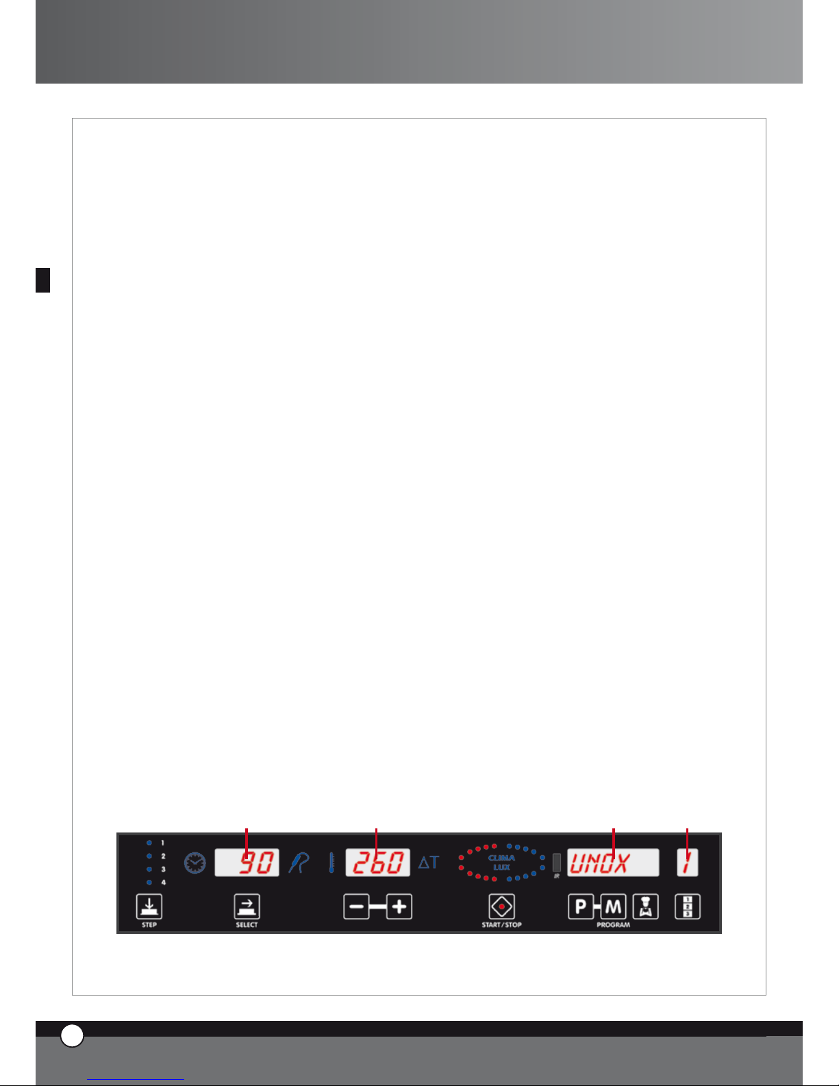
3.2 LAYOUT OF THE CONTROL BOARD
1 2 43
ENGLISH
ENGLISH
4
3
ENGLISH
ChefTop™ - BakerTop™
Page 5
3.3 POWER UP / POWER DOWN
When the power to the oven is supplied, the control
board automatically turns on.
After 15 minutes if any button is not touched and there is
no appliance in use (ovens, blast chillers, holding cabinet)
the control board goes to stand by mode : only the led
“START / STOP” is on.
To return the electronic control to full power again, simply push the button.
To have the electronic control on stand by, keep the
button pushed for 6 seconds while the control is
on; to return it to full power push the button once
more.
3.4 COOKING CHAMBER LIGHT FUNCTIONING
The lights are normally turned off; every time you touch
one of the buttons they turn on for one minute then, after
one minute, they turn off. To turn them on again, push
any of the electronic control buttons.
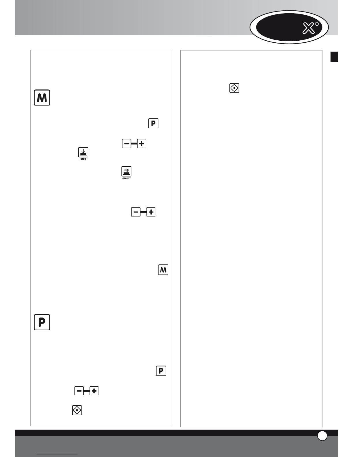
3.5 MANUAL FUNCTIONING
Any cooking program may be composed of 4 steps.
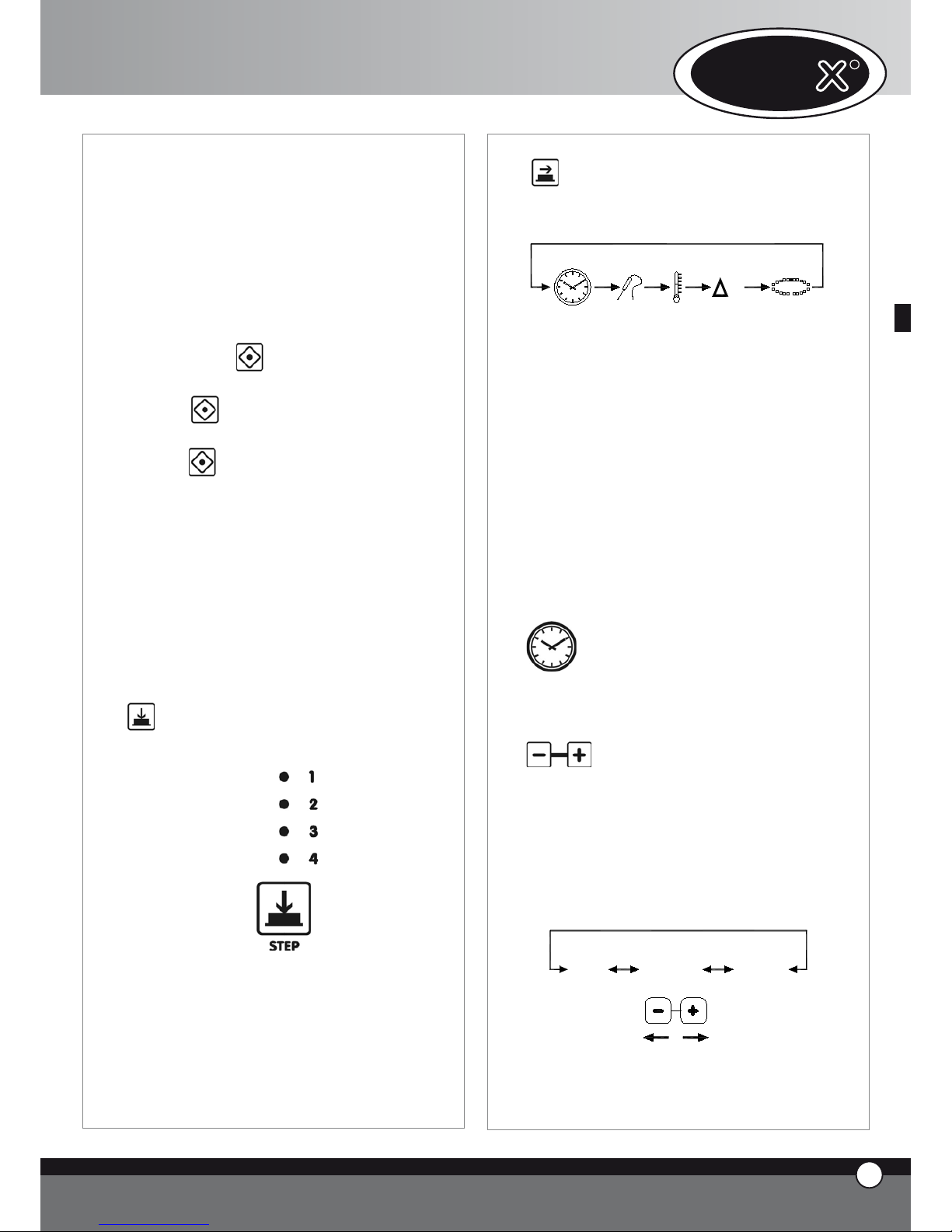
To pass from one step to another touch the button:
the selected step is indicated by the illuminated led.
For each step the user can set the following settings:
time or, as an alternative, core temperature
chamber temperature or, as an alternative, Delta T
(available only if core temperature is set)
climate inside the cooking chamber (STEAM.Maxi™
/ DRY.Maxi™).
To pass from one setting to another press the button .
•
•
•
The selected setting is indicated by one of the illuminated
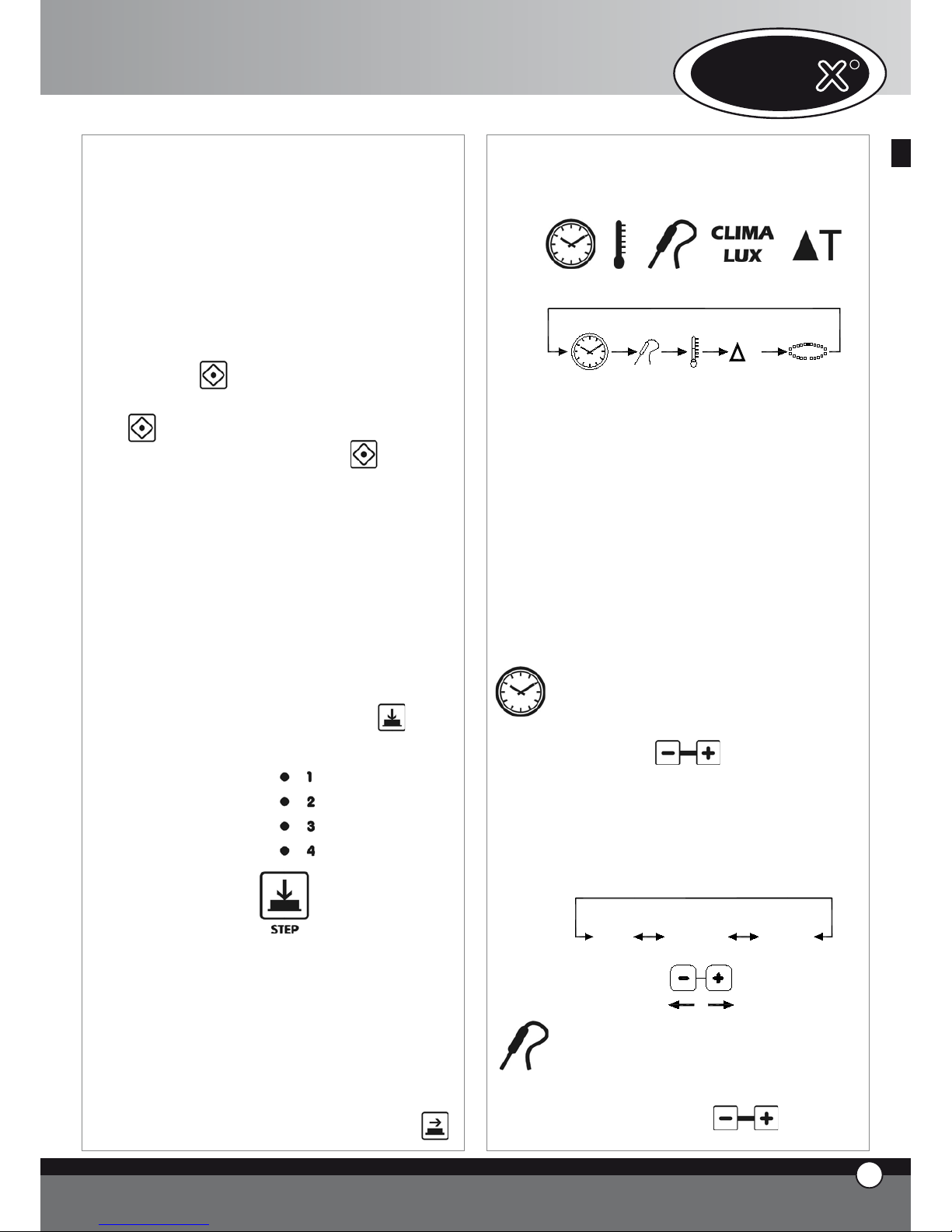
icons:
T
TIME
CORE
TEMPERATURE
CAVITY
TEMPERATURE
DELTA T
CLIMA
LUX
CLIMA LUX
Time
Core
Temperature
Cavity
Temperature
Delta T CLIMA
LUX
The settings “TIME” and “CORE TEMPERATURE” are
self cancelling: when selecting the “TIME”, the “CORE
TEMPERATURE” setting will be inoperable; vice versa, when selecting the “CORE TEMPERATURE” , the
“TIME” setting will be inoperable.
The “CHAMBER TEMPERATURE” and “Delta T” settings are also self cancelling: when selecting the “CHAMBER
TEMPERATURE”, the “Delta T” setting will be inoperable
; vice versa, when selecting “Delta T”, the “CHAMBER
TEMPERATURE” setting will be inoperable.
It is essential to select either the “TIME” or the “CORE
TEMPERATURE” setting: if none of these selections are
set, the control board does not allow the user to select
any of the following (cavity temperature, Delta T, Climate).
Time setting
The time is shown on the display panel1 and is set
with the buttons
.
When the display panel shows “inF”, the oven will
work continuously until it is manually stopped by the
user. On cooking steps 2, 3 or 4, if the HOLD “HLD”
function is selected, the fans turns only when the
heating elements are on. Every time the fans start,
the direction of rotation reverses.
STEP 1
0h 00' 9h 59'
inF
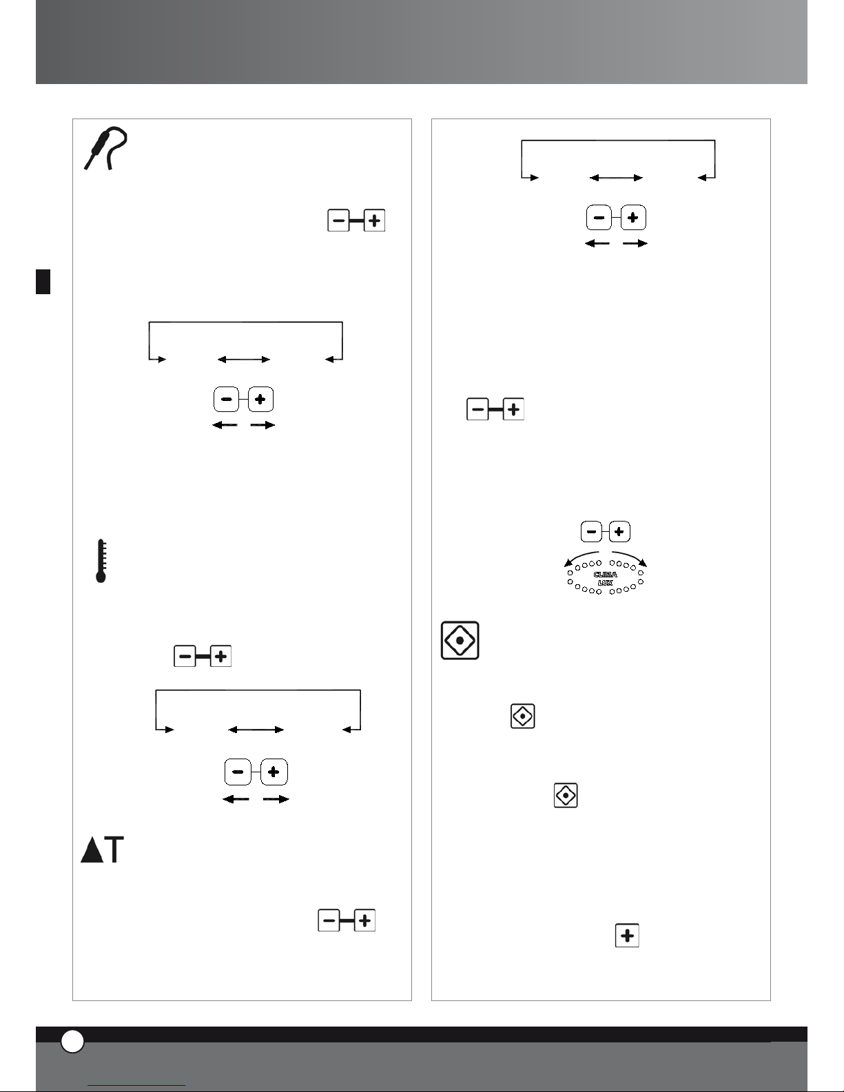
Core temperature setting
The core temperature is shown on display panel 1
and is set with the buttons
.
ENGLISH
UNO
R
4
ENGLISH
Page 6
As soon as the set core temperature is reached, the
co
oking step finishes and the following step (if selected) starts.
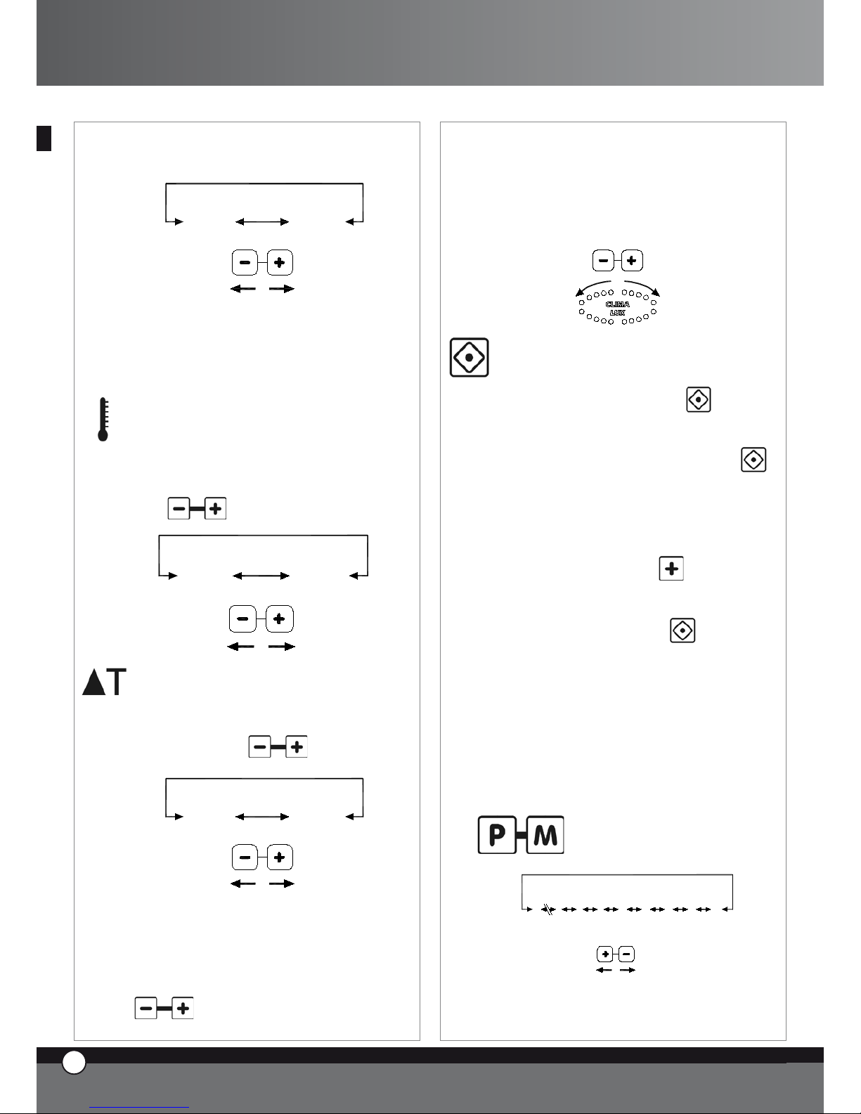
0°C 100°C
External core probe kit, XC240, is available to allow
you to connect a further small core probe, suitable
to vacuum cooking and small pieces of food.
Chamber temperature setting
The temperature inside the cooking chamber is
shown on the display panel 2 and is set with the buttons
.
260°C0°C
Delta T setting
Delta T value is shown on the display panel 2 and is
set with the buttons
.
0°C 100°C
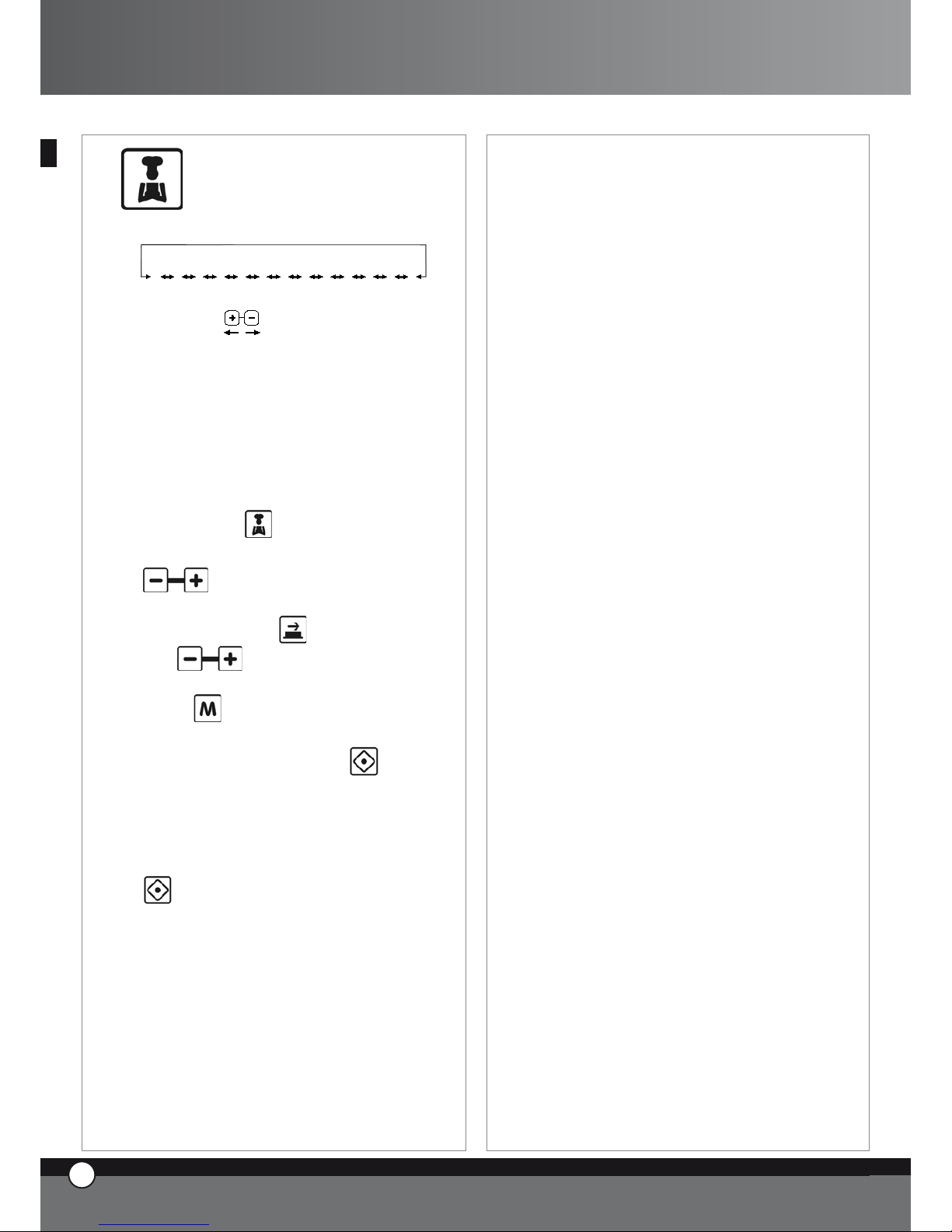
CLIMA LUX Climate setting
The setting of the climate inside the cooking cham-
ber (STEAM.Maxi™ / DRY.Maxi™) is shown
by CLIMA LUX ellipse and is set with the buttons
.
The 10 blue led’s indicate the percentage of steam
inside the cooking chamber (STEAM.Maxi™); the
10 red led’s indicate the percentage of dry air
(DRY.Maxi™).
STEAM
Maxi
DRY
Maxi
Cooking start / stop
To start a cooking cycle touch the
button.
When the cooking starts, the led “START STOP”
turns on.
To stop the cooking cycle touch the button
.
When the cooking cycle has finished, both in ma-
nual and program mode, the oven makes an audible
alarm for 15 seconds and the display 1 flashes for 45
seconds. During this 45 seconds time the “START /
STOP” led remains on:
if you touch the button
you increase the
set cooking time. The oven automatically starts
again (with the last cooking cycle settings)
if you touch the button
the “START /
STOP” led turns off and all settings are reset.
if none of the buttons are touched, after 45 seconds have passed, “START / STOP” led turns off
and all settings are reset
Once the cooking cycle is finished, both in manual and programmed mode, if you push “P” button the 5 types display
will show “LASTP” message: by pushing “START / STOP”
button last cooking cycle that was used will start again.
3.6
Working with programs
LPUMP
L3
L2
L1
P01
P70
P02
P00
COOL
The electronic control board allows the user to set,
and select, up to 70 cooking programs.
•
•
•
ENGLISH
5
ENGLISH
ChefTop™ - BakerTop™
Page 7
The electronic control board is already set with the
cooling program (COOL) and the cooking chamber
washing programs (L1, L2, L3, LH20), for use with
the automatic washing system XC404 if connected.
Program setting - by the user
To set a program proceed as follows:
• the first display shows “Prg”, by pushing button it is possible to select the type you need to change; to change the type push buttons.
• push button and the first display on your
left will show “PRE” message and all the 4 step
leds turns off. By pushing button, you set
the temperature as absolute value or as difference:
the backlighted chamber temperature icon or the
backlighted Delta T icon turns on, and you can set
the required value by pushing
but-
tons.
• select the required cooking settings (time, core
temperature, cavity temperature, Delta T, climate); as for manual working, every cooking program can be composed by 1 to 4 steps
• to save the program press and hold the
button for 5 seconds (after 5 seconds have passed you will hear a bleep) the program is now
saved.
Use of saved programs, cooling pro
-
gram
To call up a program saved by the user, the cooling
program or a washing program follow the procedure below :
• enter program mode by touching the button
• select the required program by touching the buttons
• start the selected program by touching the button
• when the selected program starts, the led “START
ENGLISH
7
ENGLISH
UNO
R
6
ENGLISH
STOP” turns on
• while the cooking program is in operation it is not
possible to modify the program settings.
• it is possible to stop the program by touching the
button
When you start the cooking program, the oven starts
the pre-heating phase: the cooking chamber is heated up to 30°C more than the chamber temperature originally set in the first cooking step. While the
pre-heating phase is on, all the leds and display panels remain turned off apart from: “START / STOP”
led, the display panel 1 which shows the message
“PRE”, and the display panel 3 which shows the selected program. When the required temperature is
reached (step 1 chamber temperature + 30°C) the
oven will make a continuous audible bleep and the
display panels show the settings of the first cooking
step. After you’ve opened the door of the oven,
loaded the food and closed the door, the cooking
program automatically starts.
Once the cooking cycle is finished, both in manual
and programmed mode, if you push “P” button the
5 types display will show “LASTP” message: by pushing “START / STOP” button last cooking cycle
that was used will start again.
Washing programs
The control board is pre-set with 3 washing programs (L1 short, L2 medium, L3 long) + a rinsing
program LH2O + a program for the pre-loading of
the detergent and rinse aid pumps. (LPUMP).
Cooking chamber cooling down program
“COOL”
“COOL”, this program is used for cooling down the
cooking chamber, it allows the fans inside the chamber
to rotate whilst the heating elements remain off. The
program works also with the door of the oven open.
While “COOL” program is working, the display shows
cooking chamber temperature.
Important!
It is not possible to remove the fan guard without
the proper removal tool, thanks to the presence of
a fixing screw. If it is necessary to remove the fan
guard for service, do not forget to disconnect the
appliance from the electrical supply.
Page 8
3.7
“ChefUnox™” - “BakerUnox™”
COOKING CYCLES
PIZZA
BREAD
BAKE
POLLO
FRIES
STEAM
STEAM PRB1
ROAST
GRILL
SLOW
VACUO
REGEN
PIZZA ITALY
The electronic control board “ChefTouch™” - “BakerTouch™” is programmed with a series of automatic
cooking cycles pre-set at the UNOX factory: by simply
selecting the required cooking cycle, it is possible to automatically cook an endless range of food.
For every cooking program, you have the possibility to
modify some of the settings in order to personalise the
required cooking results.
To use one of the pre-set programs, proceed as indicated below:
touch the button
select the required program by using the buttons
it is possible to modify the value of the flashing setting by touching the button and, afterwards,
the
buttons (If this new value needs to
be saved in the selected cooking program, touch and
hold the button for 5 seconds until you hear the
confirmation bleep).
start the program by touching the button
when the program starts, the led “START / STOP”
turns on
while the cooking program is in operation it is not
possible to modify the program settings.
it is possible to stop the program by touching the
button
AUTOMATIC COOKING PROGRAMS FOR DIFFERENT PRODUCTS
“PIZZA ITALY” Cooking program
Progr am for the cooking of “thin” based pizza.
Variable setting: cooking time.
It is recommended to use the UNOX “FAKIRO™”
plate TG860 especially studied for this purpose by Unox.
•
•
•
•
•
•
•
“PIZZA” Cooking program
Program for the cooking of “thick” based pizza.
Variable setting: cooking time.
“PANE” Cooking program
Program for the cooking of bread and similar products.
The core probe is used to check the cooking level of the product.
Variable setting: core temperature, in order to obtain a variation in the finished product.
“BAKE” Cooking program
Program for the cooking of pastry products.
The core probe is used to check the cooking level of the
product.
Variable setting: core temperature, in order to obtain a variation in the finished product.
“POLLO” Cooking program (only for ChefTop™ series)
Program for the cooking of roast chicken, poultry and
game.
Variable setting: core temperature, in order to obtain a variation in the finished product.
The program is composed by a pre-heating step at 210°C
and in 4 steps with temperature from 180 to 250°C.
It is recommended to use the UNOX “Pollo” grid
GRP810, especially studied for this purpose by UNOX.
“FRIES” Cooking program (only for ChefTop™ series)
Program for the cooking of french fries.
Variable setting: core temperature, in order to obtain a variation in the finished product.
It is recommended to use the Unox “NoFry” tray
GRP815 especially studied for this purpose by UNOX.
AUTOMATIC COOKING PROGRAMS
FOR DIFFERENT TYPE OF COOKING
“REGEN” Regeneration program (only for ChefTop™ series)
Regeneration program allows the user to regenerate previously cooked and preserved foods.
Variable setting: time of the regeneration process.
“VACUO” Cooking program (available only if the exter-
nal core probe kit XC240 is connected) (only for
ChefTop™ series)
Program for the cooking of vacuumed food.
Variable setting: core temperature in order to adapt the
cooking to different kinds of food.
ENGLISH
8
ENGLISH
7
ENGLISH
ChefTop™ - BakerTop™
Page 9
The use of the very thin core probe XC240 avoids damage to the plastic vacuum bags.
“STEAM” Cooking program (only for ChefTop™ series)
Suitable for meat, fish, vegetables and other products.
Variable setting: core temperature, in order to obtain a variation in the finished product
With this cooking program the fans inside the cooking
chamber turn only clockwise (there is no reversing gear).
(there is no reversing gear).
The amount of water released inside the cooking chamber depends on the set temperature: higher is the temperature, lower is the quantity of water. The oven automatically calculates the right amount of water to release
on the basis of the set temperature.
“STEAM PRB1” Cooking program (available only if the
external core probe kit XC240 is connected) (only
for ChefTop™ series)
The external core probe is required.
Suitable for delicate or small products such as sausages,
fish and steamed vegetables thanks to the use of the external core probe which checks the cooking level.
Variable setting: core temperature, in order to obtain a variation in the finished product
With this cooking program the fans inside the cooking
chamber turns only clockwise (there is no reversing gear).
“SLOW” Cooking program (only for ChefTop™ series)
The core probe is required.
Suitable for slow cooking at low temperatures, ideal for
large joints of meat.
Variable setting: core temperature, in order to obtain a variation in the finished product from rare to well done, when
the cooking has finished, the product is maintained at a temperature of 70 °C.
“ROAST” Cooking program (only for ChefTop™ series)
The core probe is required.
Suitable for the cooking of roast meat or fish.
Variable setting:. core temperature, in order to obtain a variation in the finished product
It is recommended to use the UNOX “Black” tray
TG835 especially studied for this purpose by UNOX.
“GRILL” Cooking program (only for ChefTop™ series)
Suitable for grilling of meat, fish and vegetables.
Important note: to cook fish it is suggested to use the
ROAST++ cooking program.
Variable setting: core temperature, in order to obtain a vari-
ENGLISH
UNO
R
8
ENGLISH
ation in the finished product from rare to well done
It is recommended to use the UNOX “FAKIRO™ Grill”
plate TG845 especially studied for this purpose by UNOX.
3.8
MANAGEMENT OF MULTIPLE
APPLIANCES USING THE SAME
CONTROL PANEL
The digital control panel “ChefTouch” - “Baker-
Touch” allows the user to control a variety of UNOX
ChefTop™ - BakerTop™ appliances connected to
the oven. In addition , the introduction of the MASTER
& SLAVE system allows the management , with a single
digital control, multiple ovens. The oven that is used to
control all other appliances, becomes the MASTER oven.
The ovens controlled by the MASTER oven become
SLAVE ovens, and their digital control is inactive. The
MASTER and SLAVE digital control boards are, in case of
emergency, interchangeable.
The selection of the appliance to control is made with the
button and the controlled appliance is shown by the
display panel 4.
Number – corrensponding appliance chart
Appliance
number
Appliance
code
Device
1 ChefTop™ Oven - master
2 ChefTop™ Oven - slave 2
3 ChefTop™ Oven - slave 3
4 XK304 Blast chiller
5 XL314
Holding cabinet
7 XC 314 Hood
8 XC224 Reverse osmosis system
Appliance
number
Appliance
code
Device
1
BakerTop™ Oven
- master
2
BakerTop™ Oven
- slave 2
3
BakerTop™ Oven
- slave 3
5 XL 404
Prover
7 XC 414 Hood
8 XC224 Reverse osmosis system
When installing UNOX appliances in a column, this kind of
Page 10

technology allows the user to work in a very ergonomic
way, by using the same working logic.
4. COOKING PRINCIPLES
4.1 Cooking variables
Time
This variable depends a lot on the quantity of food you
put in the oven.
The larger the quantity of food, the longer the cooking
time and vice versa.
A shorter cooking time than that required by the food
results in the food being under cooked. A longer cooking
time than that required by the food causes the burning of
the food surface.
Cavity temperature
The exact setting of the temperature inside the cavity
guarantees a proper cooking of the food, both inside and
outside.
A lower temperature than the proper one dries the
food rather than cooking it.
A higher temperature than the proper one burns the
surface while the core remains uncooked (sometimes
this result is desired, especially with meat).
Hot dry air
Hot dry air system “DRY.Maxi™”, patented by UNOX,
allows the user to extract the humidity, created by the
product while cooking, from the chamber, thus maintaining a dry environment. In this way the product becomes crispy and crumbly outside (for example: bread,
croissants), while the internal part is dry with an even
structure.
Steam
The introduction of the variable steam (STEAM.Maxi™)
and its different combinations with the temperature allow different types of cooking:
steaming (only steam);
mixed convection-steam cooking (air + steam).
4.2 Chef’s suggestions for even cooking
Preheating
It is always better to pre-heat the oven to a temperature
at least 30-50°C higher than the one required for cooking, in order to reduce the effects of heat loss due to the
opening of the door.
Type of trays and pans
To obtain a perfect cooking quality and an even browning
of the product, it is better not to use high sided containers,
as they do not allow the correct circulation of hot air.
Free space between pans
•
•
•
•
For even cooking it is important to check that you have
at least 3 cm of free space between the product and the
upper pan.
Quantity of food
To obtain the best results it is important not to overload
the oven, and to check, in the case of bread and pastry,
the orientation of the food on the trays compared with
the air flow.
Core probe positioning
For its correct functioning, it is essential to insert the core
probe, from the top to the bottom, in the thickest part of
the product, until you reach the centre.
In case of foods with reduced thickness, the core probe
should be inserted horizontally to the support surface.
IMPORTANT
Convection ovens need lower cooking temperatures (2040°C less) than those normally used in static ovens.
Pay attention when opening the door!!!
Heat and steam could cause burns.
4.3 Convection cooking
Temperature from 30°C to 260°C
Convection cooking is done by hot dry air that circulates
around the oven chamber. This allows the heat to be
perfectly distributed, consequently, it is possible to have
even cooking.
The results are perfectly cooked food both on the surface, with a golden crust, and internally.
Suitable for: Cooking au gratin, Roasting and Grilling.
Advantages: Possibility to cook at the same time different
types of food such as vegetables, meat, fish, without the
cross transfer of flavours (as long as the required cooking
temperature is the same for all the cooked dishes).
Foods with free running juices should always be placed at
the bottom of the oven chamber.
4.4 Mixed Steam-Convection Cooking
Temperature from 30°C to 260°C
Steam from 30% to 90%
The cooking is made by the combination of hot dry air and
steam, evenly distributed inside the chamber. It is surely
the most profitable and efficient of the cooking methods
used today. Cooking times and weight loss are considerably reduced. At the same time, the food remains tender
and flavoursome.
Suitable for: Roasting meats, Braising, Stewing,Cooking
of Fish.
Chef’s suggestions:
For roasting it is better to use a perforated pan or a grid,
this way it will not be necessary to turn the food continually.
By placing a non-perforated pan on the bottom of the oven
ENGLISH
10
ENGLISH
9
ENGLISH
ChefTop™ - BakerTop™
Page 11
chamber,you will be able to collect the meat juices.These
can be used at a later time to make a stock,gravy or sauce.
4.5 Steaming
Temperature from 48°C to 130°C
Steam 100%
The use of ventilated steam is one of the most delicate
ways of cooking food. With this kind of cooking the food
does not lose any liquid; therefore the nutritional contents, the appearance and the weight of the food remain
unaltered.
Suitable for :
Low temperature steaming: Vegetables, Fruit,
Fish,Terrines, Soufflés, Pâtés, Vacuum-Cooking.
Steaming: Vegetables, Fruit, Eggs, Meat, Fish,Seafood.
Intensive steaming: Potatoes,Root Vegetables
Chef’s Suggestions:
To cook leaf vegetables with steam, it is suggested to initially slightly
moisten the food, in order to avoid the drying out of the leaves.
In addition, to avoid the dispersion of the food, inside the
chamber due to air flow, you can use two baskets (No Fry,
one as a base and another, turned upside down, as a cover).
4.6 Convection Baking
Temperature from 30°C to 260°C
Convection baking is done by hot dry air that circulates
around the oven chamber. This allows the heat to be perfectly distributed, consequently, it is possible to have even
baking results at all the points of a single pan and on all
the pans. Even baking is also guaranteed when the oven
is fully loaded.
Pastry is perfectly baked both on the surface, with a golden crust, and in the internally, with a uniform structure
and a constant residual humidity.
Suitable for:
Baking of Short Pastry, Puff Pastry, Tart Pastry,
Ccream-puff Pastry
Baking of Sponge cake
Baking of Cookies
Chef’s suggestions:
To obtain the best results in pastry it is necessary to have
a higher distance between the trays, and a higher distance
between the products on the trays.
For products with a light mass ie; meringues it is preferable
to use the air reduction kit, in order to prevent their movement on the trays.
4.7 Convection + Humidity Baking
Temperature from 30°C to 260°C
Humidity from 10% to 20%
The baking is made by hot air with the addition of a variable percentage of humidity, according to the type of food
that has to be baked.
Suitable for:
•
•
•
•
•
•
ENGLISH
11
ENGLISH
UNO
R
10
ENGLISH
Baking of leavened dough, such as bread
Baking of sponge cakes, panettone, croissants ,pain au
chocolate.
Chef’s suggestions:
The use of the humidity at the beginning of the baking makes
leavening easier; subsequently, the humidity should be reduced, or even completely eliminated, to obtain the final
crispness and golden surface.
4.8 Convection + Dry Air Baking
“DRY.Maxi™” System (UNOX Worldwide Patent)
Temperatures from 30°C to 260°C
Dry air from 10% to 100%
This is an innovative system that allows the humidity, generated by the product when baking, to be extracted from
the chamber, thus maintaining a dry environment.
The product, thanks to its dry and even internal structure, appears crispy and crumbly.
Suitable for:
Baking of Croissants
Baking of Cookies
Baking of Bread
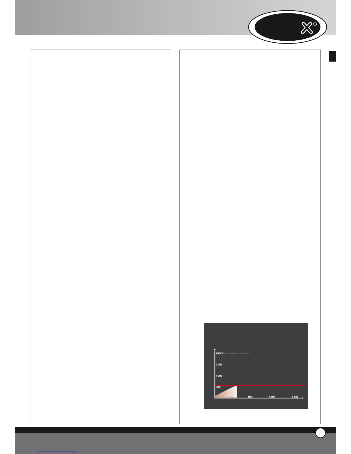
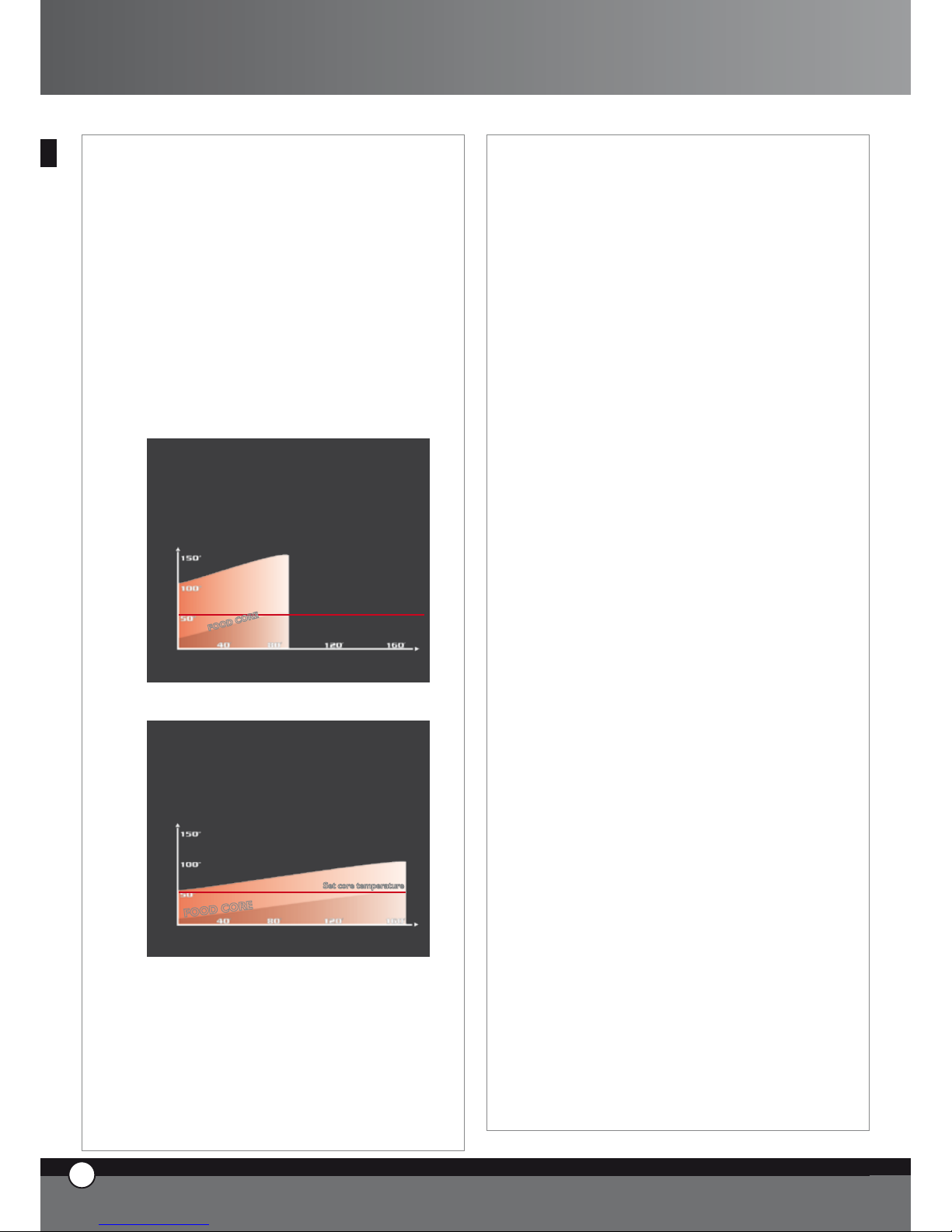
4.9 Cooking with Core Probe + Chamber Temperature
Temperatures from 0°C to 100°C
With this kind of cooking, the core temperature and the
chamber temperature have to be set.
The core probe measures the rise of the temperature
inside the product during the cooking process, the end
of the probe has to be inserted in the thickest part of the
food in the centre.With this system, it is no longer necessary to set the time, the oven, will automatically turn off
when the set core temperature is reached, or it will pass
to the following programmed step.
Core Probe cooking is useful to optimise the cooking of
different foods and avoid to continuously checking the
food during its various cooking stages.
Core probe + 100°C ∆T
Sonda al cuore + ∆T a 100°C
Core probe + Cavity temperature
cavity
Set core temperature
C
A
V
I
T
Y
Time in minutes
Temperature
•
•
•
•
•
Page 12
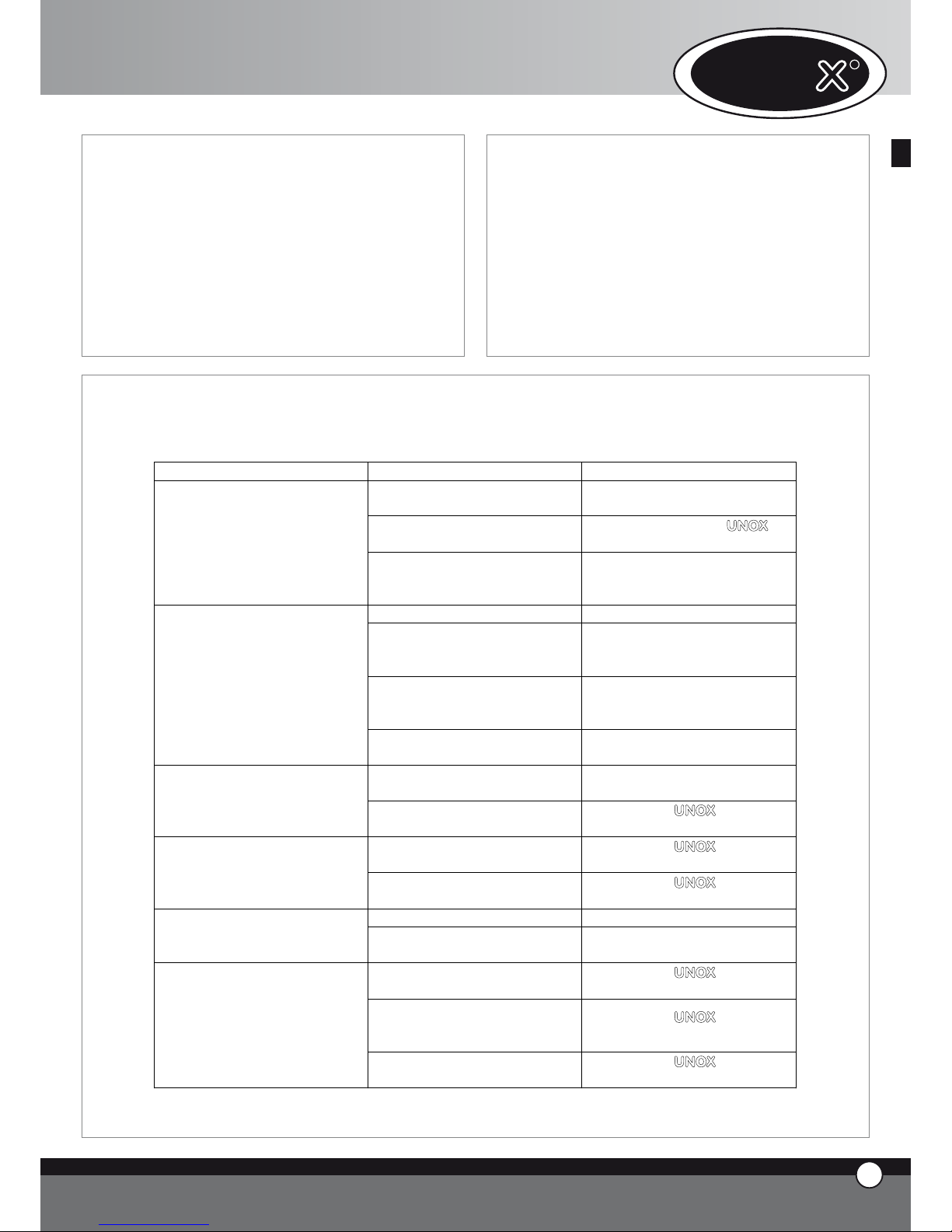
4.10 Cooking with Core Probe + Delta T
Temperature from 0°C to 260°C
In this case you have to set the desired temperature
at the core of the food and the Delta T (difference between the core and the chamber temperature)
CHAMBER TEMPERATURE =
CORE TEMPERATURE + SET DELTA T
In this way the chamber temperature will increase gradually, keeping the difference between the product core
temperature and the chamber temperature you set constant during the cooking cycle. This kind of cooking will
allow you to obtain very soft and delicate cooking, especially useful for large joints of meat.
Core probe + 100°C ∆T
C
A
V
I
T
Y
Time in minutes
Temperature
Set core temperature
F
O
O
D
C
O
R
E
Core probe + 50°C ∆T
F
O
O
D
C
O
R
E
C
A
V
I
T
Y
Set core temperature
Time in minutes
Temperature
5. CONNECTION WITH THE EXTERNAL
WORLD
The digital control panel of the “ChefTop™” -
“BakerTop™” ovens has been preset to easily connect
the oven to the external world through the present and
future systems of communication: USB, Bluetooth™, serial connections, etc.
ENGLISH
11
ENGLISH
The USB interface kit XC226 is available, and allows the
following functions:
Insertion of cooking programs.
Changes in operational parameters (ex: probe setting).
Diagnostics of problems.
Saving of the trends with regard to temperatures
inside the oven chamber or inside the blast chiller
chamber (necessary data for HACCP system)
Connection to a printer (HACCP)
You can find further information included in the kit.
6. ORDINARY MAINTENANCE
The appliance must be regularly serviced (at least once a
year) by a qualified Unox service technician.
Any maintenance operations must be carried only by a
qualified UNOX technician.
Before starting any maintenance operation, it is necessary
to disconnect the appliance from the electrical power
supply and allow it to cool down.
6.1 REPLACEMENT OF THE INTERNAL LAMP
To replace the internal lamp:
disconnect the appliance from the power supply and
allow it cool down.
remove the lateral supports
unscrew the glass cover and replace the lamp with
one with the same characteristics.
Inspect the lamp glass seal and replace if required.
screw the glass cover back in
reassemble the lateral supports
7. SPECIAL MAINTENANCE
All maintenance operations must be only be carried out
by a qualified UNOX technician.
Before starting any maintenance operation it is necessary
to disconnect the appliance from the electrical power
supply and allow it to cool down.
Removal of the back panel will allow access to all internal
components for service and maintenance.
7.1 RESETTING OF THE SAFETY THERMOSTAT
The appliance is supplied with a safety thermostat with a
manual reset. This safety thermostat is needed to protect
the appliance from overheating. When activated, it cuts
off the electrical supply to the heating elements and the
display panel shows the message “EF4”.
This safety device can be found on the bottom part of the
back panel of the oven: to reset the thermostat,remove
the black cover and push in the small central pin.
If the safety thermostat activates again, contact your nearest UNOX service centre.
•
•
•
•
•
•
•
•
•
•
•
11
ENGLISH
ChefTop™ - BakerTop™
Page 13
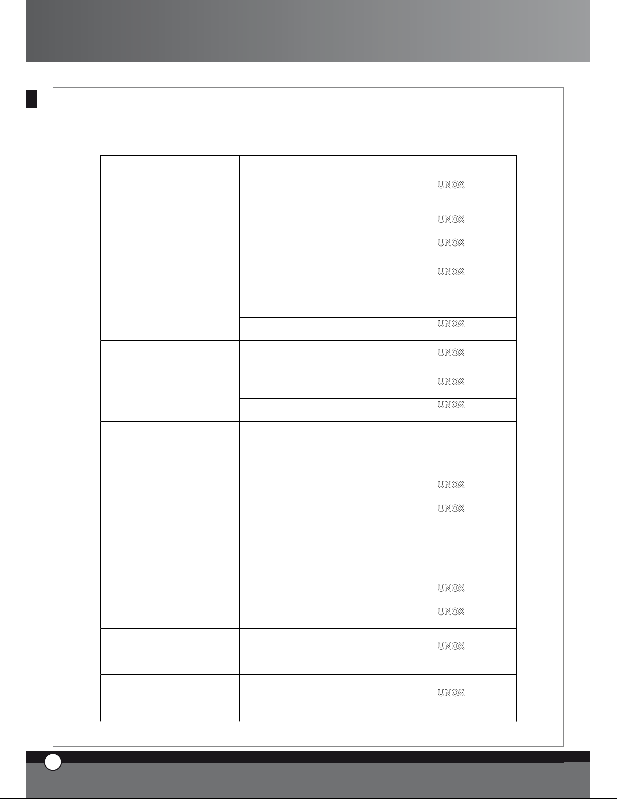
9. MALFUNCTIONS – PROBLEMS CAUSES AND REMEDIES
The guide below will help the user rectify minor faults.
ENGLISH
12
ENGLISH
UNO
R
12
ENGLISH
BREAKDOWN CAUSE SOLUTION
The supply mains voltage is
missing
Restore the voltage
Intervention of one of the fuses on
the power board
Apply to a qualified UNOX
technician for service
The oven is completely turned off
The electrical connection to the
mains has not been made in the
correct way
Check the connection of the
appliance to the mains
The water inlet valve is closed Open the water inlet valve
The connection to the water
supply or to the tank has not been
made in the correct way
Check the connection to the
water supply or to the tank
The tank is empty (in case the
appliance is connected to an
external tank)
Pour water in the tank
The humidity control of the oven
is on, but the water does not
come out of the pipes
The filter on the water inlet is
blocked
Clean the filter
The door of the oven is open or
not properly closed
Close the door in the correct way
The oven does not start even
though you have set the time or
the core temperature and pressed
START / STOP button
Damaged door magnetic micro
switch
Apply to a UNOX qualified
technician for service
Damaged door seal
Apply to a UNOX qualified
technician for service
There is water coming out though
the door and the sealing even
though the door is closed
Loose door mechanism
Apply to a UNOX qualified
technician for service
Blown lamp Replace the lamp
The oven light does not turn on
Loose lamp
Place correctly the lamp in the
lamp holder
The fans do not reverse their
rotation
Apply to a UNOX qualified
technician for service
One of the fans is not rotating (in
case of oven with more than one
motor)
Apply to a UNOX qualified
technician for service
The cooking is not even
One of the heating elements is
broken
Apply to a UNOX qualified
technician for service
8. TURNING OFF IN CASE OF
MALFUNCTION
In case of malfunction it is necessary to disconnect the
appliance:
switch off the electrical power supply isolator switch,
that is between the appliance and the network.
contact your nearest UNOX service centre.
•
•
Page 14
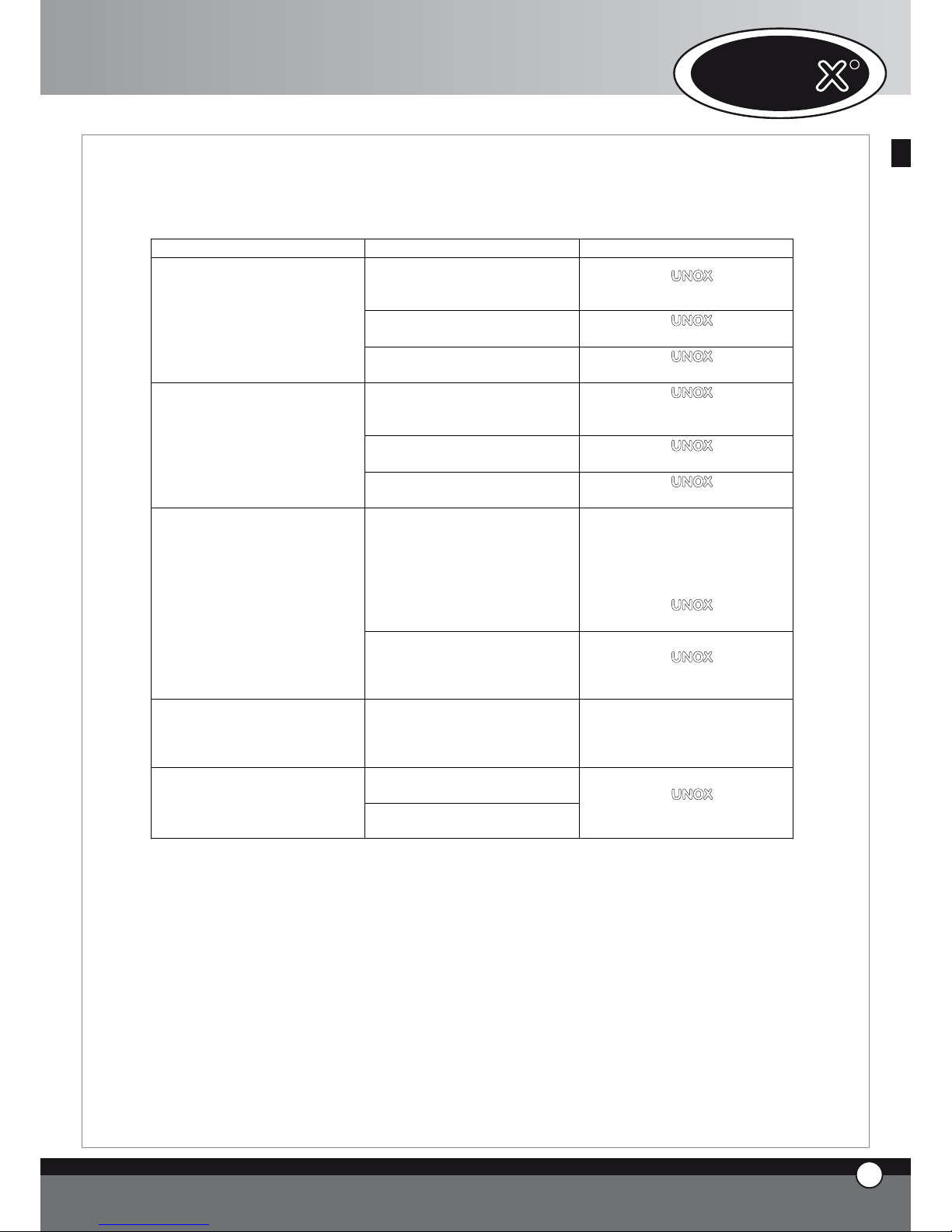
10. ERROR MESSAGES
10.1 OVEN ERROR MESSAGES
BREAKDOWN CAUSE SOLUTION
The connection wires of the
chamber probe 1 are
disconnected from the power
card
Apply to a UNOX qualified
technician for service
Damaged cavity probe 1
Apply to a UNOX qualified
technician for service
The display panel 1 shows
continuously the message EF1
Damaged power card
Apply to a UNOX qualified
technician for service
The connection wires of the cavity
probe 2 are disconnected from
the power board
Apply to a UNOX qualified
technician for service
Damaged cavity probe 2
Apply to a Unox qualified
technician for service
The display panel 1 shows
continuously the message EF2
Damaged power card
Apply to a UNOX qualified
technician for service
The connection wires of the core
probe 2 are disconnected from
the power card
Apply to a UNOX qualified
technician for service
Damaged core probe
Apply to a UNOX qualified
technician for service
The display panel 1 shows
continuously the message EF3
Damaged power card
Apply to a UNOX qualified
technician for service
Intervention of the thermic
protection of one of the motors
Disconnect the oven from power
supply, wait for the appliance to
cool down and restart the oven: if
the display shows again the
message EF4
Apply to a UNOX qualified
technician for service
The display panel 1 shows
continuously the message EF4
Damaged power card
Apply to a UNOX qualified
technician for service
Intervention of the safety thermic
device
Disconnect the oven from power
supply, wait for the appliance to
cool down and restart the oven: if
the display shows again the
message EF5
Apply to a UNOX qualified
technician for service
The display panel 1 shows
continuously the message EF5
Damaged power card
Apply to a UNOX qualified
technician for service
Control board / Power card
connecting cable is damaged or
disconnected
Display no. 1 shows continuously
EF6 message
Oven power card is damaged
Apply to a UNOX qualified
technician for service
Display no. 1 shows continuously
EF7 message
Lost of communication between
the oven and connected
accessories
Apply to a UNOX qualified
technician for service
ENGLISH
11
ENGLISH
13
ENGLISH
ChefTop™ - BakerTop™
Page 15
ENGLISH
12
ENGLISH
10.2 BLAST CHILLER ERROR MESSAGES
BREAKDOWN CAUSE SOLUTION
The connection wires of the cavity
probe are disconnected from the
power card
Apply to a UNOX qualified
technician for service
Damaged chamber probe
Apply to a UNOX qualified
technician for service
The display panel 1 shows the
message EA1
Damaged blast chiller power card
Apply to a UNOX qualified
technician for service
The connection wires of the core
probe are disconnected from the
power card
Apply to a UNOX qualified
technician for service
Damaged core probe
Apply to a UNOX qualified
technician for service
The display panel 1 shows the
message EA2
Damaged blast chiller power card
Apply to a UNOX qualified
technician for service
Overpressure in the refrigeration
circuit
Disconnect the blast chiller from
the power supply, wait for about
20 minutes, and connect again the
appliance: if the display shows
again the message EA3
Apply to a UNOX qualified
technician for service
The display panel 1 shows the
message EA3
Damaged blast chiller power card
Apply to a UNOX qualified
technician for service
Display no. 1 shows continuously
EA4 message
Filters working limit reached Take out the filter and wash it
Oven / blast chiller connecting
cable is damaged or disconnected
Display no. 1 shows continuously
EA5 message
Blast chiller power card is
damaged
Apply to a UNOX qualified
technician for service
UNO
R
14
ENGLISH
Page 16
10.3 HOLDING CABINET ERROR MESSAGES
BREAKDOWN CAUSE SOLUTION
The connection wires of the
chamber probe are disconnected
from the power card
Apply to a UNOX qualified
technician for service
Damaged chamber probe
Apply to a UNOX qualified
technician for service
The display panel 1 shows
continuously the message EL1
Damaged holding cabinet power
card
Apply to a UNOX qualified
technician for service
The connection wires of the
humidity probe are disconnected
from the power card
Apply to a UNOX qualified
technician for service
Damaged humidity probe
Apply to a UNOX qualified
technician for service
The display panel 1 shows
continuously the message EL2
Damaged holding cabinet power
card
Apply to a UNOX qualified
technician for service
Oven / holding cabinet connecting
cable is damaged or disconnected
Display no. 1 shows continuously
EL3 message
Holding cabinet power card is
damaged
Apply to a UNOX qualified
technician for service
10.4 HOOD ERROR MESSAGES
ENGLISH
11
ENGLISH
15
ENGLISH
ChefTop™ - BakerTop™
BREAKDOWN CAUSE SOLUTION
The connection wires of the
temperature probe are
disconnected from the power
card
Apply to a UNOX qualified
technician for service
Damaged temperature probe
Apply to a UNOX qualified
technician for service
The display panel 1 shows
continuously the message EC1
Damaged hood power card
Apply to a UNOX qualified
technician for service
Oven / hood connecting cable is
damaged or disconnected
Display no. 1 shows continuously
EC2 message
Hood power card is damaged
Apply to a UNOX qualified
technician for service
Page 17

ENGLISH
12
ENGLISH
10.5 OSMOSIS SYSTEM ERROR MESSAGES
BREAKDOWN CAUSE SOLUTION
Pressure transducer is damaged
Transducer / power card
connecting cable is damaged or
disconnected
Display no. 1 shows continuously
EO1 message
Osmosis power card is damaged
Apply to a UNOX qualified
technician for service
Liter-counter is damaged
Liter-counter / power card
connecting cable is damaged or
disconnected
Display no. 1 shows continuously
EO2 message
Osmosis power card is damaged
Apply to a UNOX qualified
technician for service
Display no. 1 shows continuously
EO3 message
Filters working limit reached
Apply to a UNOX qualified
technician for service
Display no. 1 shows continuously
EO4 message
Inlet water pressure is too low
Verificare che arrivi acqua
all’ingresso dell’osmosi
Oven / osmosis connecting cable
is damaged or disconnected
Display no. 1 shows continuously
EO5 message
Osmosis power card is damaged
Apply to a UNOX qualified
technician for service
UNO
R
16
ENGLISH
Page 18
B. INSTRUCTION FOR THE
INSTALLER
1. WARNING
All the operations of installation, assembly, service and
assistance must be carried out by qualified personnel according to current laws and regulations.
Please read carefully the instruction manual before the
installation and commissioning of the appliance.
The appliance must be unaltered (check for any transport
damage).
Remove all informative material from the chamber.
2. PRELIMINARY OPERATIONS
2.1 INSTALLATION SITE
Before placing the appliance, please verify the overall dimensions and the exact position of the electrical and water connections and of the fumes exhaust as indicated on
the attached file “Technical Data”.
Avoid to install the oven on places where there is a risk
of explosion.
Avoid to install the oven outdoor without a proper and
complete rain proof protection.
Avoid to install and use the oven inside small rooms where
there is insufficient air change.
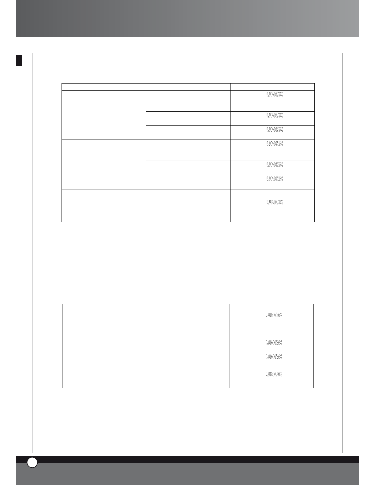
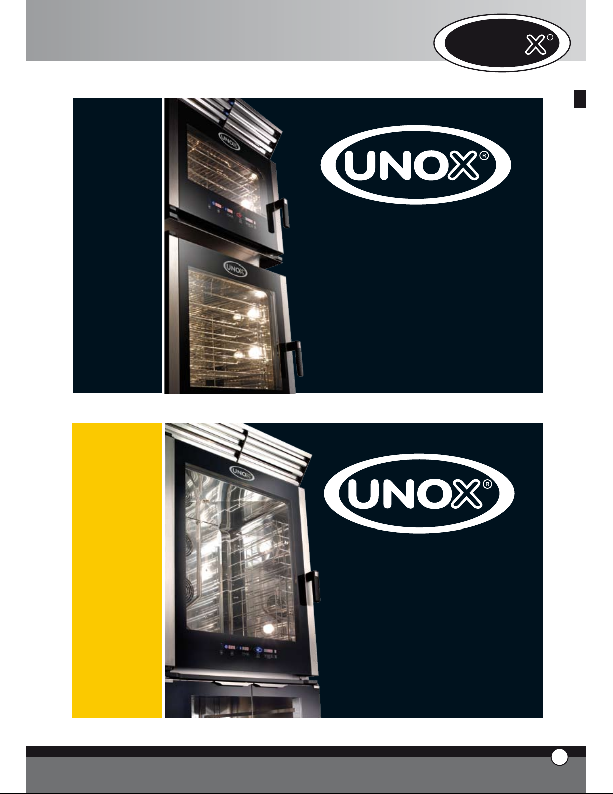
2.2 PRESETTING FOR POSITIONING
You will find the feet inside the appliance.They must be
fitted to the oven.
Never use the appliance without its feet.
Remove the drip tray from the back of the oven by using
a screwdriver.
Place the oven on one side.
Insert the feet in the indicated positions and the tray
guides as shown in the picture.
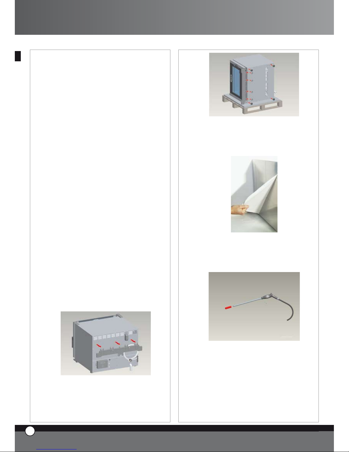
2.3 REMOVAL OF THE PROTECTIVE FILM
Carefully remove all the protective film from the external
walls of the appliance.
Pay attention not to leave any residue of glue.If there
should be any residue of glue please remove it with an
appropriate solvent.
Remove the probe protection.
2.4 POSITIONING
Place the appliance respecting the safety standards indicated below.
Place the appliance so that its back can be easily reached
in order to make the electrical connections and to provide the necessary service.
The appliance is not suitable for built-in installation
or side by side positioning.
It is recommended to leave 5 cm of free room all around
the appliance.
13
ENGLISH
17
ENGLISH
ChefTop™ - BakerTop™
Page 19
With particular reference to the ovens, all models must
be placed upon a support, such as a prover, a stand or a
table. Avoid to install the oven near heat sources.
Never install the appliance on the floor.
If the appliance is placed near walls, partitions, kitchen
cabinets, decorated edges, etc., it is recommended these
are made of non combustible material.
Otherwise, they must be coated with non combustible
thermal insulating material and the fire prevention standards must be respected.
Do not install the appliance near a fryer because
some fat may enter inside the oven and settle on
the electric parts, causing malfuncitoning of the
equipment.
Avoid to install the appliance near inflammable substances containers, eg.: gas cylinders.
Verify that the appliance is installed on a flat and
level surface.
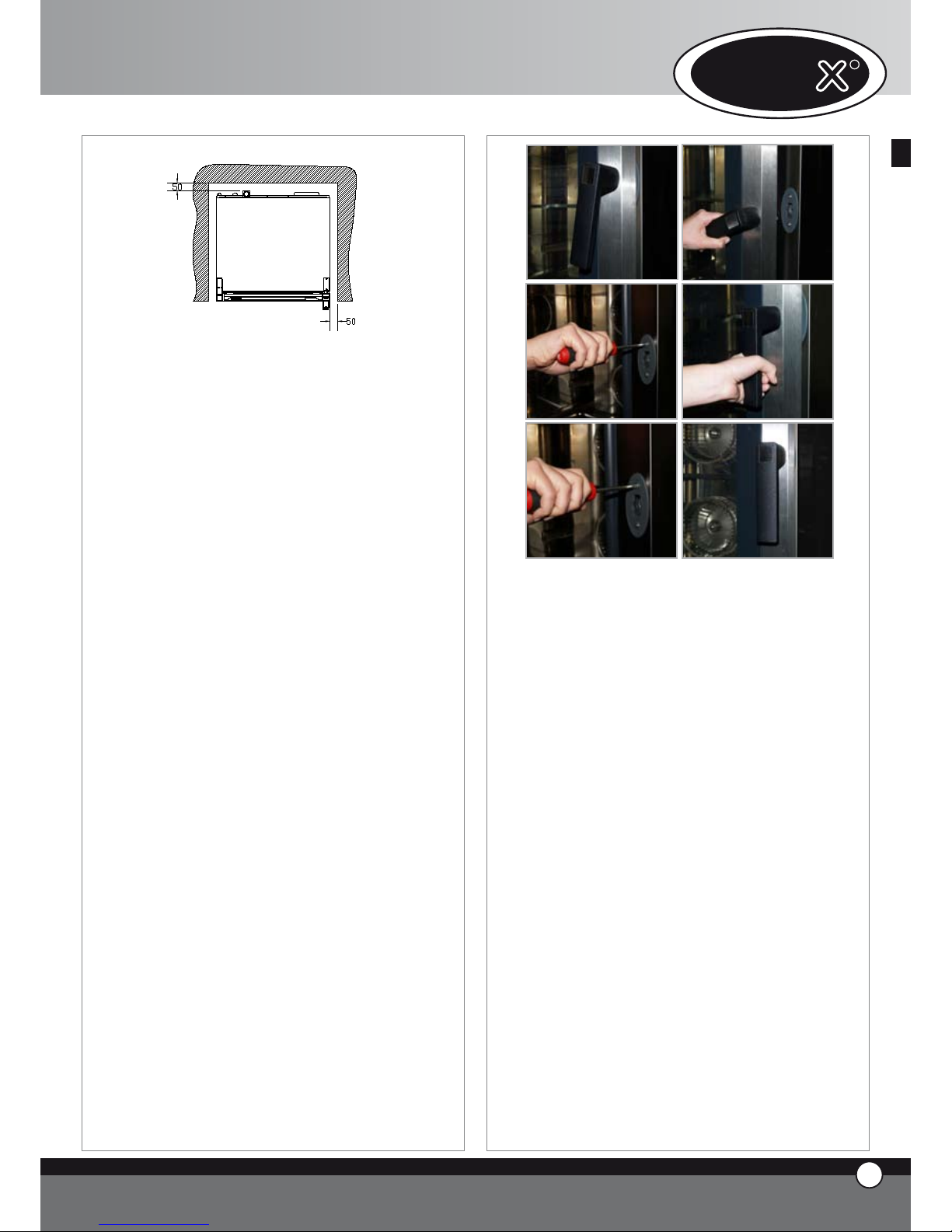
In case, once the oven is placed, the door handle does not
properly close the door, it is necessary to accommodate
the handle latch, as described here below:
• open the door of the oven (pic.1), slightly unloose the
fixing screws of the door latch (pic.2)
• close the door and turn the handle to lock it (pic.3)
• if the door remained closed and the handle is perfectly
in vertical position, open the door and tightly fix the fixing
screws of the latch (pic.4).
• in case the problem is not solved, repeat the procedure
unloosing more the latch fixing screws.
WARNING! In case the oven is placed on a non perfectly flat surface, the handle does not properly close: if
the surface is only lightly deformed, it is possible to solve
the problem by following the latch accomodation procedure described here above; this procedure can not be
used to solve the problem in case the surface shows big
deformations.
3. ELECTRICAL CONNECTION
3.1 WARNING
The connection to the electrical power supply system
must be carried out according to the current local regulations.
Before connecting the appliance, make sure that the voltage and the frequency correspond to those stated on the
data plate of the appliance.
The appliance must be placed in such a way that the connecting plug to the network can be easily reached.
Place an omni-polar switch between the appliance and
the network in such a way that it will be easily accessible after the installation. The contacts of this switch must
have a minimum opening distance of 3 mm and the switch
must have an appropriate input (for example: thermalmagnetic switch).
The use of a safety switch for fault current is suggested.
When the appliance is working, the power supply voltage
must not diverge from the value of the nominal voltage,
indicated on the data plate, by more than ± 10%.
14
ENGLISH
UNO
R
18
ENGLISH
Page 20
3.2 CONNECTION TO THE ELECTRICAL SUPPLY
MAINS
1. Ovens equipped with cable and Schuko plug (single
phase 230V): it is sufficient to plug in the equipment
to the appropriate outlet (the outlet must be suitable
to the issued plug)
2. Ovens equipped with cable (three-phase 400V +
neutral): the issued cable is with 5 wires, therefore
it has to be connected directly to an electric board
or suitable outlet. To make different connections it
is necessary to replace the cable with the correct
one on the basis of the information indicated in the
attached file “Technical Data”. You find the connection schemes on internal side of the terminal board
cover.
The replacement of the cable must be done by authorised personnel.
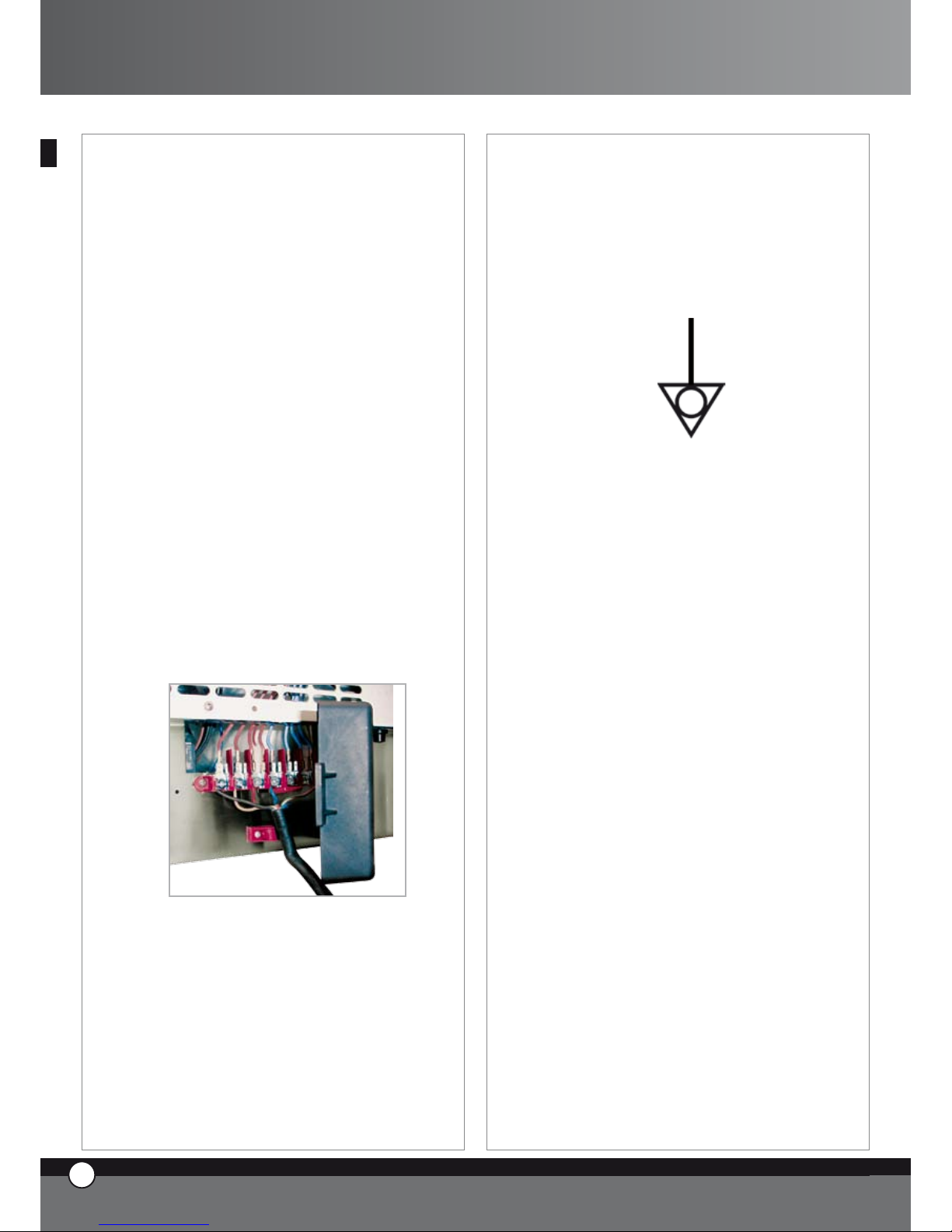
To replace the cable proceed as follows:
Open the terminal board cover by unscrewing the fixing screw
Connect the wires according to the chosen connection scheme
Fix the connecting cable through the proper cable
fastener
Close the terminal board cover and tighten the fixing
screw
WARNING:
Connect the electrical cable to the terminal board as
shown on the drawing: insert the copper bridge and the
electrical cable together under the screw. Tighten the
screw paying attention that the cable and the copper
bridge are well fixed under the screw.
A wrong connection can cause the overheating and
the melting of the terminal board.
The appliance must be connected to the ground
line of the network.
•
•
•
•
3.3 EQUIPOTENTIAL SYSTEM
The appliance must be included in an equipotential system
whose efficiency must be properly checked according to
the current laws. This connection must be done between
different appliances through the terminal marked with
the symbol: simbolo morsetto equipotenziale
The equipotential conductor must have a minimum section of 10 mm2.
4. WATER CONNECTION
4.1 WARNING
It is necessary to place a mechanical filter and a shut-off
valve between the water system and the appliance.
As required by current laws, the appliance is equipped
with 2 metres of pipe, the respective pipe fitting (3/4”)
with non-return valve and mechanical filter.
Before connecting the water pipe to the appliance please
let some water flow to clear the pipe of any obstructions.
The water used in the appliance must have a pressure
value between 1 and 3 bar and a maximum temperature
of 30°C.
4.2 TREATMENT OF WATER
The water must have a maximum hardness of 5 °FH (this
avoids formation of limestone inside the chamber of the
oven).
It is strongly recommended to use a demineralising appliance (reverse osmosis unit) in order to avoid limestone
and/or other minerals depositing inside the oven.
The UNOX reverse osmosis system, code XC224 is available for this purpose. This system is directly controlled
by the control board of the oven through a self•diagnosis
system.
19
ENGLISH
ChefTop™ - BakerTop™
Page 21
UNO
R
20
ENGLISH
5 DRAIN CONNECTION
5.1 WARNING
The water coming our from the waste outlet pipe can be
very hot (90°C).
Proper pipes for high temperature must be used for this
connection.
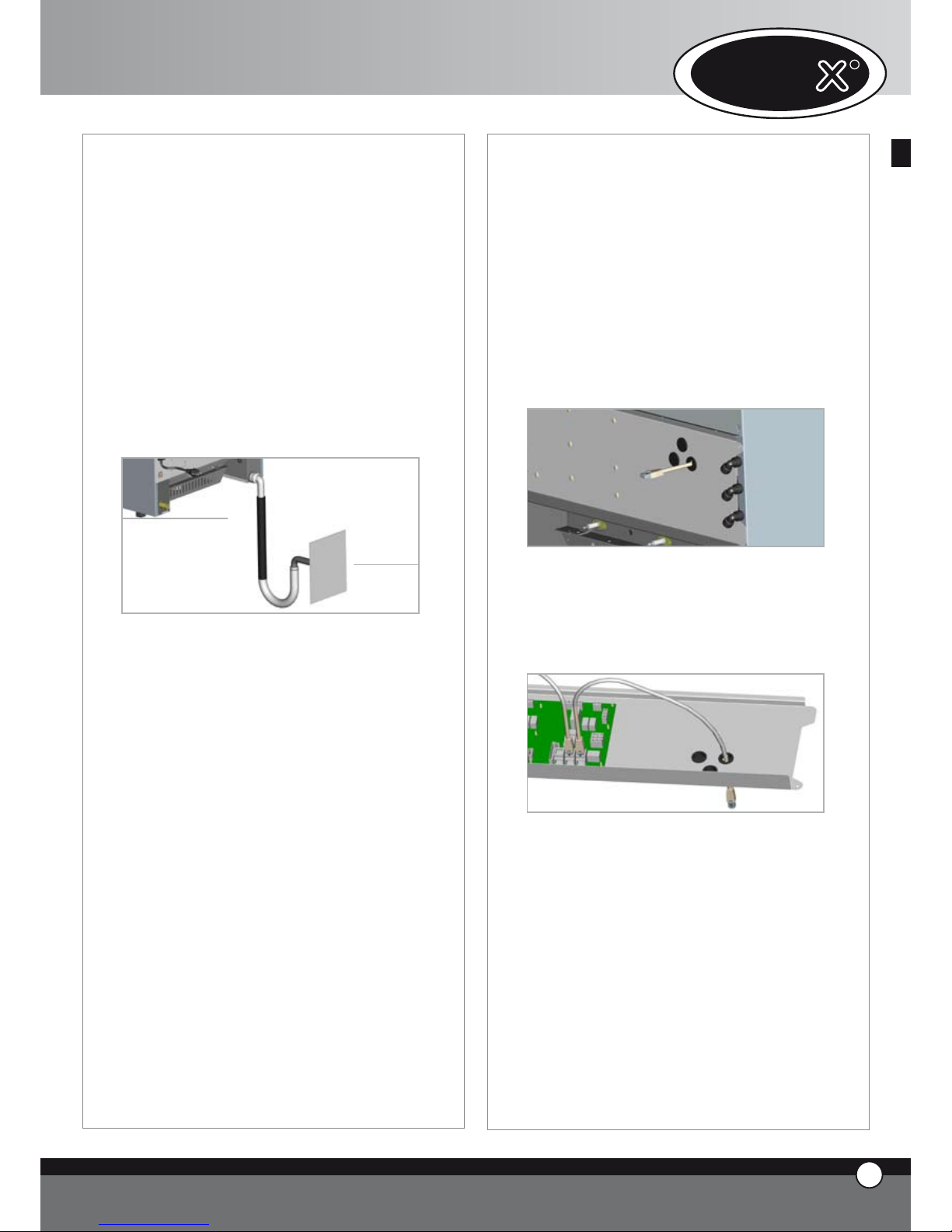
5.2 WATER DRAIN
You find the waste outlet pipe on the rear of the oven. It
has to be connected to an open tundish drain in compliance with current regulations through a rigid or flexible
heat resistant pipe; the diameter of the pipe cannot be
smaller than diameter of the drain connection. The length
of the pipe cannot be longer than one metre.
Avoid reductions in diameter and tight bends along the
whole length of the waste pipe run.
The waste pipe must remain at least 20 cm below the
drain connection to allow the liquids to drain.
5.3 COOKING CHAMBER EXHAUST
The exhaust outlet of the cooking chamber is positioned
on the rear of the oven, at the top.
Do not stack any object and or material on the outlet as
this could cause a blockage of the fumes. Please ensure
that the exhaust outlet is correctly vented and the vicinity
of the outlet is clear of objects and materials that may be
damaged by the fumes.
It is suggested to place the oven below an extraction
hood or to install the UNOX aspiration hood, code
XC314 for ChefTop™- XC414 for BakerTop™, or the
UNOX steam condenser, code XC114. In all installations
please extract the fumes through the UNOX tube, code
TB1520A0, avoiding tight bends in the pipework run.
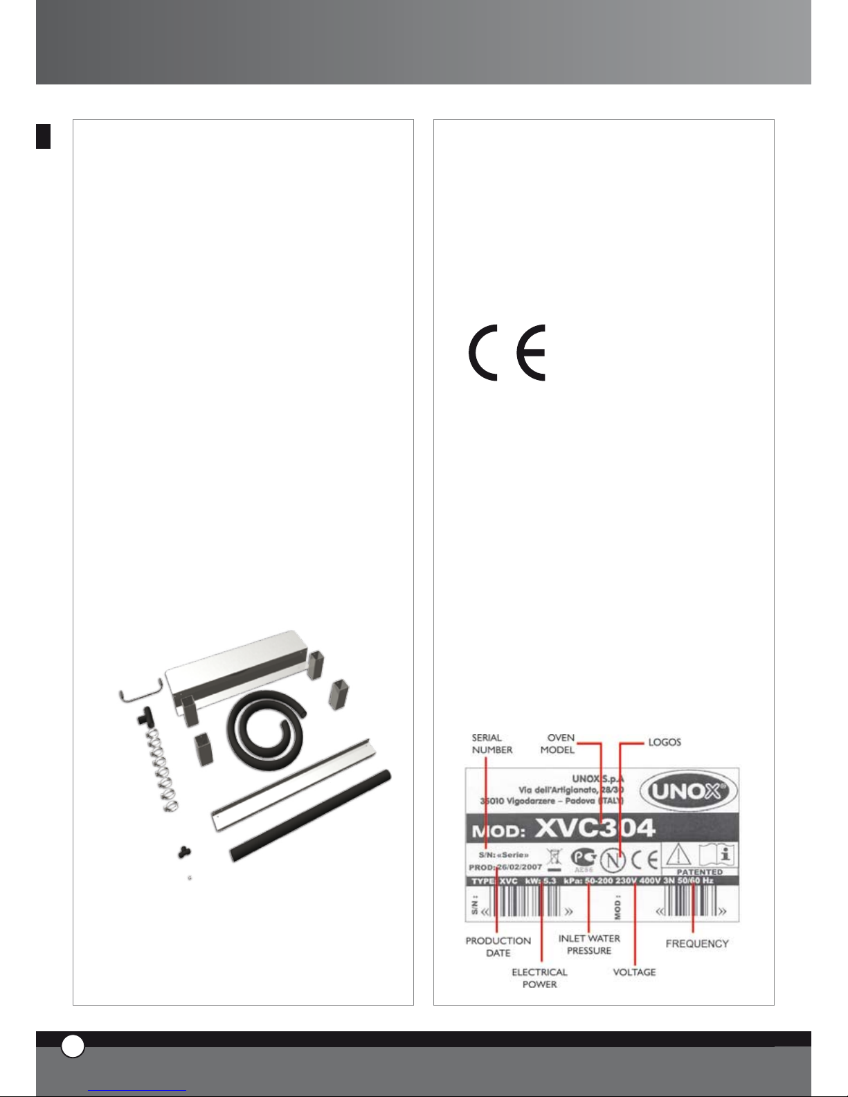
6. ACCESSORIES CONNECTIONS (PROVER, HOOD, BLAST CHILLER, ETC.)
The digital board of the oven controls all the accessories
(hood, holding cabinet, blast chiller, reverse osmosis system).
The accessories controlled by the oven are connected
through RJ45 connectors that are positioned on the rear
of the oven.
To connect the cables proceed as follows:
• remove the protection cover to enter the electrical
system
• by using a cutter make a vertical cut on one of the rubber caps placed on the panel on the back of the oven
• enter an end of the RJ45 cable through the cut on the
rubber cap
• connect the cable end with the proper female connector on the power card (you can use any one of the three
connectors)
• replace the protection cover by fixing the screw
Now the accessory is recognized and connected to the
oven
Please refer to relevant instructions manual for the correct use ot the connected accessory
Page 22
7.
REPLACEMENT OF THE DOOR GLASSES
7.1 WARNING
The internal glass of the door is a low emissive tempered
glass.
The glass surface towards the cooking chamber is covered by a transparent metallic film that reduces the heat
transfer to the interspace between the two glasses and
reflects the heat inside the chamber.
If you need to replace the internal glass, pay attention
to correctly place the glass with the low emissive side
towards the cooking chamber.
If the low emissive side is wrongly turned towards the
outside, the temperature of the external door surface will
rise with risk of burns for the user and possible blowing
of the glass!
To check the low emissive side you need to use a proper
tester set at a maximum range of
2 KOhm. Point the two test prods on the glass surface at
5 cm one from the other: the low emissive surface will
show around 50 Ohm of resistance, while the other side
will show infinite resistance.
8. OVENS STACKING
In the event of stacking multiple ovens it is essential
to assemble the UNOX stacking kit, code XC680 for
ChefTop™ - XC681 for BakerTop™, which will maintain the correct distance between the ovens.
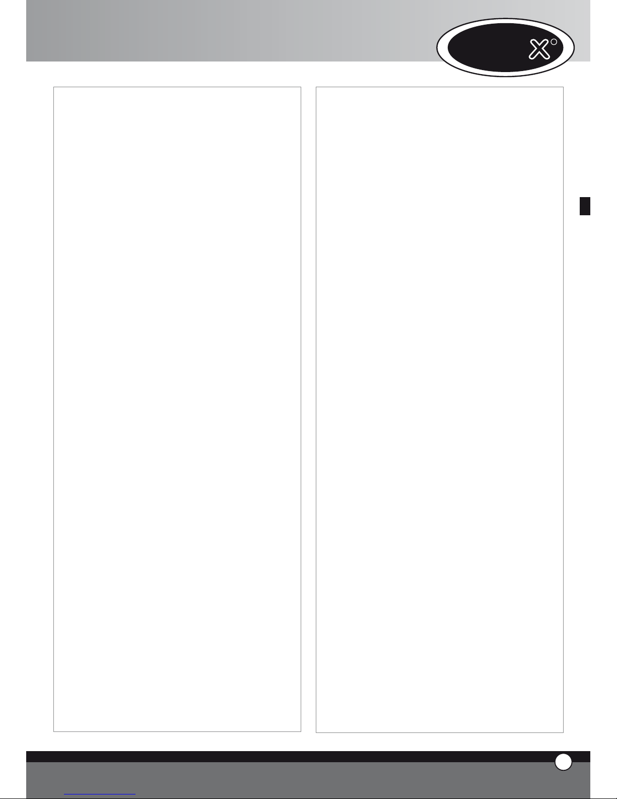
C. CERTIFICATIONS
Producer: UNOX S.p.A.
Address: Via Dell’Artigianato 28/30
I-35010 Vigodarzere, Padova, Italy
Product: Mixed steam convection oven for profession-
al use
Family: ChefTop™ - BakerTop™
REFERENCE LAWS
The “CE” marking on the appliances indicated in this
manual refers to following UE directives:
ELECTRIC MIXED STEAM CONVECTION OVENS
XVC - XBC SERIES:
Low Voltage Directive 2006/95/EC
following the rules:
EN 60335-2-42:2003
EN 60335-1:2002; A11; A1; A12 ; A2 including possible listed national conditions/deviations for Norway
Electromagnetic Compatibility Directive 2004/108/EC
following the rules:
EN 55014-1:2000; A1; A2
EN 61000-3-2:2000; A2
EN 61000-3-3:1995; A1; A2
EN 61000-3-11:2000
EN 55014-2:1997; A1
EN 50366:2003 ; A1
DATA PLATE
•
•
•
•
•
•
•
•
•
21
ENGLISH
ChefTop™ - BakerTop™
Page 23
UNO
R
22
ENGLISH
Bakertop™
ChefTop
™
www.unox.com
www.unox.com
BakerTop
™
Page 24

INDEX
A. ISTRUCTIONS POUR L’UTILISATEUR Page 02
1. AVERTISSEMENTS Page 02
2. NETTOYAGE DU FOUR Page 02
3.
PANNEAU DE COMMANDES ChefTouch - BakerTouch
Page 03
4. LES PRINCIPES DE CUISSON Page 09
5.
COMMUNICATION AVEC LE MONDE EXTERNE
Page 12
6. MAINTENANCE ORDINAIRE Page 12
7. MAINTENANCE EXTRAORDINAIRE Page 12
8. COUPURE EN CAS DE PANNE Page 12
9 LES PANNES PLUS FRÉQUENTES Page 13
10. MESSAGES D’ERREURS Page 14
B.
INSTRUCTIONS POUR L’INSTALLATEUR
Page 17
1. AVERTISSEMENTS Page 17
2. OPÉRATIONS PRÉLIMINAIRES Page 17
3. BRANCHEMENT ELECTRIQUE Page 18
4. RACCORDEMENT HYDRIQUE Page 19
5 RACCORDEMENT EVACUATIONS Page 19
6. LIAISON DES ACCESSOIRES Page 19
7. SUBSTITUTION VERRES DE PORTE Page 20
8. SUPERPOSITION DES FOURS Page 20
C. CERTIFICATIONS Page 21
INTRODUCTION
Gentil Client; Merci et Compliments pour avoir acheté
un four de la ligne ChefTop™ - BakerTop™. On sou-
haite que ce soit le début d’une collaboration positive de
longue durée.
Comme vous savez, la ligne des fours ChefTop™ -
BakerTop™ et tous ses équipements complémentaires
(cellule de refroidissement rapide, cellule de maintien en
température, plaques et grilles spéciales) ont été étudiés
pour vous permettre de compléter n’importe quel processus de cuisson que soit simple ou bien très difficile.
L’innovant panneau de commandes ChefTouch -
BakerTouch vous permettra de commander, à l’aide
d’un seul contrôle, tous les équipements UNOX liés au
four.
La nouveauté plus importante est celle des CUIS-
SONS AUTOMATIQUES ChefUnox - BakerUnox
lesquelles vous permettront de cuisiner, sans avoir plus
la nécessité d’introduire les paramètres temps, température chambre de cuisson, température à cœur, une infinité des plats.
C’est suffisant sélectionner le type de cuisson voulu parmi
les suivants SLOW (lente), STEAM (vapeur), ROAST (rôtir),
GRILL (griller) et ChefUnox - BakerUnox cuisinera
pour vous des plats délicieux et savoureux.
À part le type de cuisson automatique, vous aurez aussi la
possibilité de choisir parmi six cuissons automatiques de
familles de produits: BAKE (cuire au four) , BREAD (pain),
POLLO (poulet) , PIZZA ITALY, PIZZA, FRIES (pommes
frittes).
L’utilisation d’une ou de deux sondes à cœur supplémentaires, douées d’aiguilles extra fines et externes au four,
vous consentira en plus d’effectuer des parfaites cuissons
sous vide et des parfaites cuissons à vapeur des aliments
particulièrement délicats ou de petites dimensions.
De toute façon, c’est toujours vous le Chef
plus important!
À l’intérieur de chaque type de cuisson automatique, vous
aurez en effet, la possibilité de personnaliser quelques
paramètres pour ajouter, en basant à vos exigences personnelles, le degré de dorage et le degré de cuisson que
vous considérez parfait.
1
FRANÇAIS
ChefTop™ - BakerTop™
Page 25
UNO
R
2
FRANÇAIS
A. ISTRUCTIONS POUR
L’UTILISATEUR
1. AVERTISSEMENTS
ATTENTION:
Prière de lire attentivement ce manuel d’instructions qui
vous fournit des indications importantes concernant la
sécurité et l’emploi de l’équipement.
Conserver avec précaution ce manuel pour toutes les ultérieures consultations des différents opérateurs.
L’équipement doit être destiné uniquement à l’emploi
pour lequel il a été expressément conçu; des autres emplois sont retenus abusifs. L’équipement peut être utilisé
pour les suivants emplois :
pour les cuissons de tous les produits de Pâtisserie et
Boulangerie, frais ou congelés;
pour les cuissons de tous les produits de Gastronomie, frais ou congelés ;
pour le reconditionnement des aliments réfrigérés ou
congelés;
pour la cuisson à vapeur des viandes, des poissons et
des légumes.
En phase de première utilisation, faire attention que le
notice d’utilisation, des sacs en plastic ou n’importe quel
autre objet, ne soient pas présents à l’intérieur de la
chambre de cuisson.
Les panneaux de commandes peuvent être actionnés seulement avec les doigts ; n’importe quel autre objet peut
provoquer des pannes et/ou des mal fonctionnements et
par conséquence ça fait déchoir la garantie.
L’appareil n’est pas conçu pour une utilisation de part de
personnes (inclus les enfants) avec des capacités mental,
physique et sensoriales réduites, ou une absence de expérience ou de connaissance de l’appareil, au moins q’îles
sont surveillées par une personne responsable pour la
leur sécurité ou qui louer donne des instructions pour
l’utilisation de l’appareil.
Les enfants doit être surveillées, pour être sur que il ne
jeux pas avec l’appareil.
L’équipement est destiné uniquement à l’emploi professionnel spécifique et doit être utilisé par un personnel
qualifié.
La température des parties externes peut dépasser les 60 °C.
Eviter de positionner des fontes de chaleur à côté de
l’équipement.
En cas de cuisson des produits extrêmement gras, poser
un récipient sur le fond de la chambre de cuisson.
En cas d’extraction des plaques qui contiennent des liquides chauds, faire attention au débordement éventuel
des liquides
•
•
•
•
Si la plaque contient des produits liquides chauds, il est
nécessaire positionner la plaque à une hauteur bien visible par l’opérateur.
Faire particulièrement attention au déplacement des récipients des aliments durant et après la cuisson: les températures peuvent être élevées et donc elles peuvent
provoquer des brûlures
Ouvrir lentement la porte: danger brûlures pour sortie
fumées et vapeurs à température élevée.
Utiliser le four avec une température ambiante comprise
entre +5 °C et +35 °C.
SONDE À CŒUR
Faire attention à l’utilisation de la sonde à cœur à l’intérieur du four parce qu’elle peut provoquer des brûlures:
utiliser des gants de protection convenables
Ne pas laisser pendre la sonde à cœur en dehors de
la porte
Extraire la sonde des aliments avant d’enlever la
plaque
Durant le fonctionnement du programme “COOL” (refroidissement chambre) les turbines du four fonctionnent
avec la porte ouverte.
Les interventions d’installation, de maintenance et de
réparation doivent être exécutées seulement pas un personnel qualifié et convenablement formé. Avant de faire
ces interventions, débrancher la tension d’alimentation
de l’équipement.
Au cas où l’équipement serait positionné sur un support
dotés de roues, faites attention que le mouvement consenti n’endommage pas des câbles électriques, des tuyauteries de l’eau, des tuyauteries d’évacuation ou n’importe
quel type de raccordements.
Éviter de saler les aliments à l’intérieur de la chambre de
cuisson.
2 NETTOYAGE DU FOUR
2.1 PREMIERE UTILISATION DU FOUR
Pour la première utilisation de l’équipement: nettoyer la
partie en métal avec de l’eau chaude et du savon et puis
rincer.
Ne jamais laver l’intérieur de la chambre de cuisson ou
bien le four avec des acides ou des produits agressifs.
Réchauffer à ce point le four à vide pour 30 mn à 200°C
pour éliminer les éventuelles odeurs de l’isolation thermique.
•
•
•
Page 26
2.2 NETTOYAGE CHAMBRE DE CUISSON
On vous conseille de nettoyer quotidiennement la chambre de cuisson pour pouvoir maintenir des niveaux d’hygiène élevés et
pour éviter la détérioration de l’acier inoxydable à l’intérieur de la chambre de cuisson. Pour ce motif, on vous conseille d’utiliser le système de lavage Rotor Klean code XC404 qui vous permettra d’exécuter le nettoyage automatique de la chambre de
cuisson.
Pour le nettoyage manuel de la chambre de cuisson, ne jamais utiliser les suivants instruments:
lance à eau à haute pression
produits acides
produits/instruments abrasifs
Pour le nettoyage manuel de la chambre de cuisson, faire comme suit:
allumer le four
poser la température à 80°C et la vapeur à 100%
laisser fonctionner le four pour 10 minutes
laisser refroidir et nettoyer avec un tissu
Si à l’intérieur de la chambre de cuisson il y a des résidus de graisse, faire attention parce que la graisse peut prendre feu.
2.3 NETTOYAGE EXTERNE DU FOUR
Débrancher le four avant d’effectuer n’importe quelle opération manuelle de nettoyage.
Ne jamais utiliser un jet d’eau en pression pour le lavage externe du four.
Utiliser seulement des tissus humides.
AVERTISSEMENT:
Avant d’effectuer n’importe quelle intervention de maintenance ou de nettoyage, il est nécessaire débrancher l’alimentation
électrique et attendre le refroidissement de l’appareil.
3. PANNEAU DE COMMANDES ChefTouch - BakerTouch
3.1 FONCTIONNEMENT DU CONTRÔLE ChefTouch - BakerTouch
Le contrôle “ChefTouch” - “BakerTouch” fonctionne en approchant le doigt au bouton en sérigraphie. (utiliser exclusive-
ment les doigts et aucun autre objet comme les couteaux, les fourchettes, etc.).
De cette façon, vous pouvez activer les fonctions et/ou introduire les valeurs voulues.
L’avantage de cette technologie est l’élimination de tous les mouvements mécaniques et donc un degré élevé de fiabilité.
Ce type de technologie permet en outre un rapide et facile nettoyage du panneau de commandes.
3.2 LAYOUT PANNEAU DE COMMANDES
1 2 43
•
•
•
•
•
•
•
3
FRANÇAIS
ChefTop™ - BakerTop™
Page 27
UNO
R
4
FRANÇAIS
3.3 ALLUMAGE / COUPURE
Quand on fournit la tension au four, le contrôle s’allume
automatiquement.
Après 15 minutes, si on n’appuie sur aucune touche et
aucun appareil est en fonction (four, cellule de refroidissement rapide, cellule de maintien en température) le
contrôle électronique va en veille (stand-by): seulement
la DEL (diode électroluminescente) “START / STOP” reste allumée.
Pour réactiver le contrôle électronique, c’est suffisant
presser le bouton
Avec le contrôle électronique allumé, en tenant pressé
le bouton pour 6 secondes, le contrôle électronique va en veille; pour le réactiver, presser de nouveau
le bouton
3.4 Logique de fonctionnement des lumières chambre
de cuisson
Les lumières restent éteintes; elles s’allument pour 1 minute quand on presse n’importe quel bouton et puis elles s’éteignent. Pour les réactiver, c’est suffisant presser
n’importe quel bouton.
3.5 Fonctionnement manuel
Chaque cuisson peut être composée de 4 phases (step).
Pour passer d’une phase à une autre, toucher le bouton
et la phase active est visualisée par la DEL (indica-
teur) illuminée.
Pour chaque phase, l’utilisateur doit introduire les paramètres suivants:
Temps ou alternativement la température à cœur
Température dans la chambre de cuisson ou alternativement, la Delta T (disponible seulement lorsque la
température à cœur est utilisée)
Climat à l’intérieur de la chambre de cuisson (STEAM.
Maxi™ / DRY.Maxi™) c.à.d (Vapeur/Séchage).
•
•
•
Pour passer d’un paramètre à un autre, utiliser le bouton
le paramètre actif est visualisé à travers une des
cinq icônes lumineuses
T
TIME
CORE
TEMPERATURE
CAVITY
TEMPERATURE
DELTA T
CLIMA
LUX
CLIMA LUX
Temp
Temperature
cœur
Temperature Delta T CLIMA
LUX
Les paramètres temps et température à cœur sont exclusifs entre eux: si on introduit le temps, le paramètre température à cœur devient inutilisable. Si on introduit la
température à cœur, le paramètre temps devient à son
tour inutilisable.
Les paramètres température chambre de cuisson et Delta
T sont exclusifs entre eux : si on introduit la température
dans la chambre de cuisson, le paramètre Delta T devient
inutilisable. Si on introduit le Delta T, le paramètre température chambre de cuisson devient à son tour inutilisable.
Il est nécessaire introduire un des deux paramètres temps
et température à cœur : si aucun de ces deux paramètres
est introduit, le contrôle ne permet plus l’introduction
des paramètres suivants (température chambre, Delta T,
Climat)
Introduction de temps
Le temps est visualisé à travers l’afficheur 1 en heures et minutes et on l’introduit en utilisant les boutons
Quand l’écriture “INF” apparaît sur l’afficheur, le four
fonctionne jusqu’au moment où l’utilisateur l’arrête manuellement. Lorsqu’on sélectionne la fonction HOLD
“HLD” dans les phases de cuisson 2, 3 OU 4, les turbines
fonctionnent uniquement lorsque les résistances sont en
marche. à chaque fonctionnement des turbines, le sens
de rotation s’inverse.
STEP 1
0h 00' 9h 59'
inF
Page 28
Introduction température à cœur
La température à cœur est visualisée à travers l’afficheur
1 et on l’introduit en utilisant les boutons
Quand on atteint la température introduite au cœur,
l’étape de cuisson est conclue et on passe à la phase successive (s’il y en a une).
0°C 100°C
Le Kit des sondes à cœur externes XC240 est disponible;
ce Kit sert pour pouvoir lier une ultérieure sonde à cœur
de dimensions réduites convenable pour les cuissons sous
vide et les cuissons des aliments de petites dimensions.
Introduction température chambre
de cuisson
La température à l’intérieur de la chambre de cuisson est
visualisée à travers l’afficher 2 et on l’introduit en utilisant
les boutons
260°C0°C
Introduction Delta T
La valeur du Delta T est visualisée à travers l’afficheur 2
et on l’introduit en utilisant les boutons
0°C 100°C
CLIMA LUX Introduction du Climat
Le climat (STEAM.Maxi™ / DRY.Maxi™) à l’intérieur
de la chambre de cuisson est visualisé à travers l’ellipse
CLIMA LUX et on l’introduit en utilisant les boutons
Les 10 DEL (indicateurs) de couleur bleue indiquent le
pourcentage de vapeur à l’intérieur de la chambre de
cuisson (STEAM.Maxi™); Les 10 DEL (indicateurs) de
couleur bleue indiquent le pourcentage de séchage (DRY.
Maxi™).
STEAM
Maxi
DRY
Maxi
Commencement / Interruption cycle de cuisson
Pour commencer une cuisson, il est nécessaire presser le
bouton
Le commencement de la cuisson est signalé par l’allumage de l’indicateur “START STOP” .
Pour arrêter la cuisson, il est nécessaire presser de nouveau le bouton
Quand le cycle de cuisson termine que ce soit en modalité manuelle ou bien programmée, le four émet un signal
sonore pour 15 secondes et l’afficheur 1clignote pour 45
secondes. Durant ces 45 secondes, la DEL (indicateur)
“START / STOP” reste illuminée.
Si on presse le bouton
on augmente le temps
et le four automatiquement repart (avec les paramètres de fonctionnements relatifs à la dernière phase
de cuisson exécutée).
•
5
FRANÇAIS
ChefTop™ - BakerTop™
Page 29
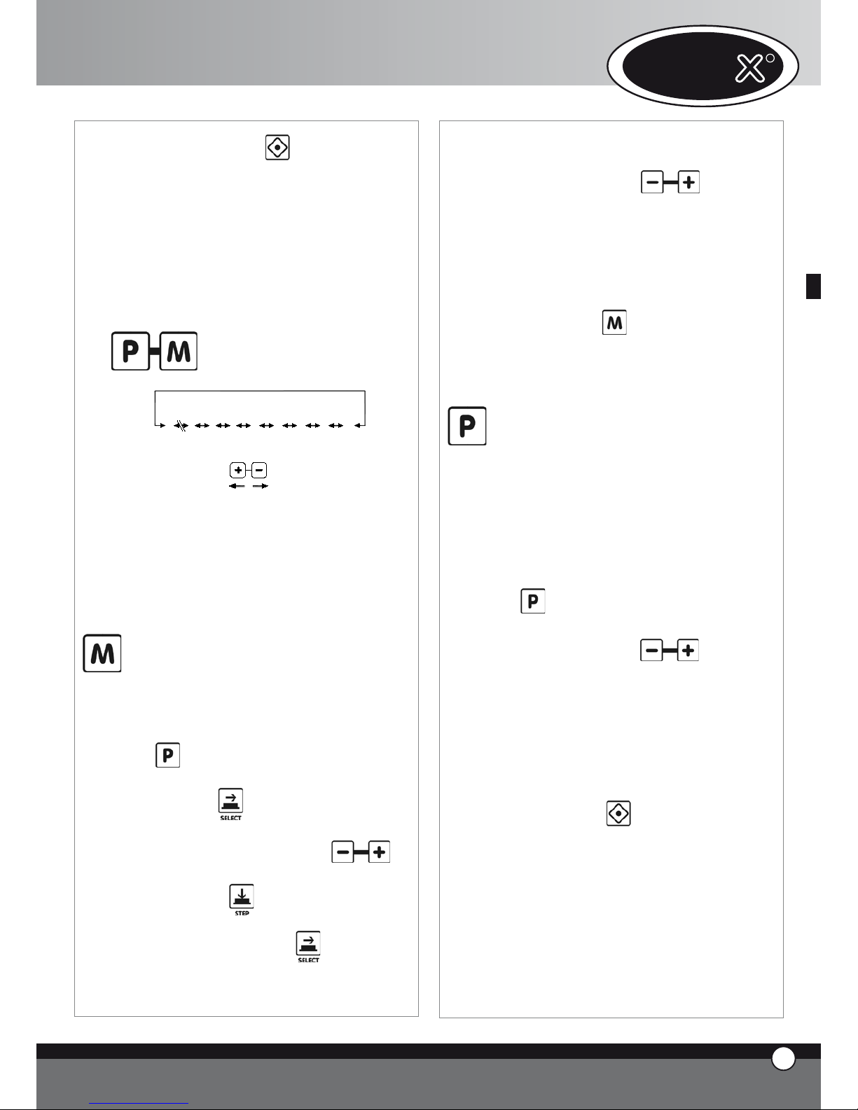
UNO
R
6
FRANÇAIS
Si on presse le bouton l’indicateur “START /
STOP” s’éteint et tous les paramètres de fonctionnement sont remis à zéro.
À la fin de chaque cycle de cuisson, que ce soit en
modalité manuelle ou bien avec un programme, en
pressant le bouton “P” sur l’afficheur 5, on voit apparaitre inscription “LASTP”:
en pressant le bouton “START / STOP” on fait par-
tir de nuoveau, le dernier cycle de cuisson qui a été
exécuté.
3.6
Fonctionnement avec programmes
LPUMP
L3
L2
L1
P01
P70
P02
P00
COOL
Le contrôle électronique permet à l’utilisateur de mémoriser, et d’extraire successivement, jusqu’aux 70 programmes de cuisson.
Le contrôle électronique contient, dans son intérieur, les
programmes pour le lavage de la chambre de cuisson (L1,
L2, L3, LH20) si le système de lavage XC404 est présent
et le programme de refroidissement (COOL).
Stockage des programmes per
l’utilisateur:
Pour mémoriser un programme, procéder comme suit:
Entrer en modalité programmes en pressant le bouton
sur le premier afficheur, l’inscription “Prg” apparait,
avec le bouton on a la possibilité de sélectionner quel caractère modifier parmi les 5; la modification est possible à travers les boutons
Sur le premier afficheur, à gauche, après avoir pressé
le bouton “Step” , l’inscription “PRE” apparait
et tous les 4 indicateurs lumineux des phases résultent éteints. A l’aide du bouton on sélectionne
si introduire la température comme valeur absolue ou
bien comme différence, on allume l’icône lumineuse
•
•
•
•
de la température de chambre de cuisson ou bien
l’icône lumineuse de Delta T et on introduit la valeur
voulue à l’aide des boutons
On introduit les paramètres de fonctionnement
(temps, température à cœur, température chambre
de cuisson, Delta T, climat); comme dans le fonctionnement manuel, chaque programme de cuisson peut
être composé de 1 à 4 phases ;
On tient le bouton
pressé pendant 5 secondes
pour stocker le programme (à la fin des 5 secondes, le
four émet un signal sonore de confirmation).
Utilisation des programmes stockés
par l’utilisateur, du programme de
refroidissement et du programme
de lavage:
Pour reprendre un programme mémorisé par l’utilisa-
teur, le programme de refroidissement ou le programme
de lavage, procéder comme suit:
Entrer en modalité programmes en pressant le bouton
Sélectionner par les boutons
le numéro du programme qu’on veut utiliser
Faire partir le programme à travers le bouton
Le démarrage du programme est signalé par
l’illumination de la DEL (indicateur) “START STOP”
Durant l’exécution du programme, la modification
des paramètres de fonctionnement est impossible
On peut interrompre l’exécution du programme en
pressant le bouton
Quand on fait démarrer un programme de cuisson, le
four exécute le pré réchauffement: la chambre de cuisson vient portée à une température qui correspond à
la température de la chambre de la première phase de
cuisson majorée de 30°C. Durant cette phase, tous les
indicateurs et les afficheurs restent éteints à l’exception
de l’indicateur “START / STOP” , l’afficheur qui visualise
l’écriture “PRE” et l’afficheur 3 qui indique le programme qu’on utilise. Quand on rejoint la température voulue
(température chambre phase 1 + 30°C) cette tempéra-
•
•
•
•
•
•
•
•
Page 30
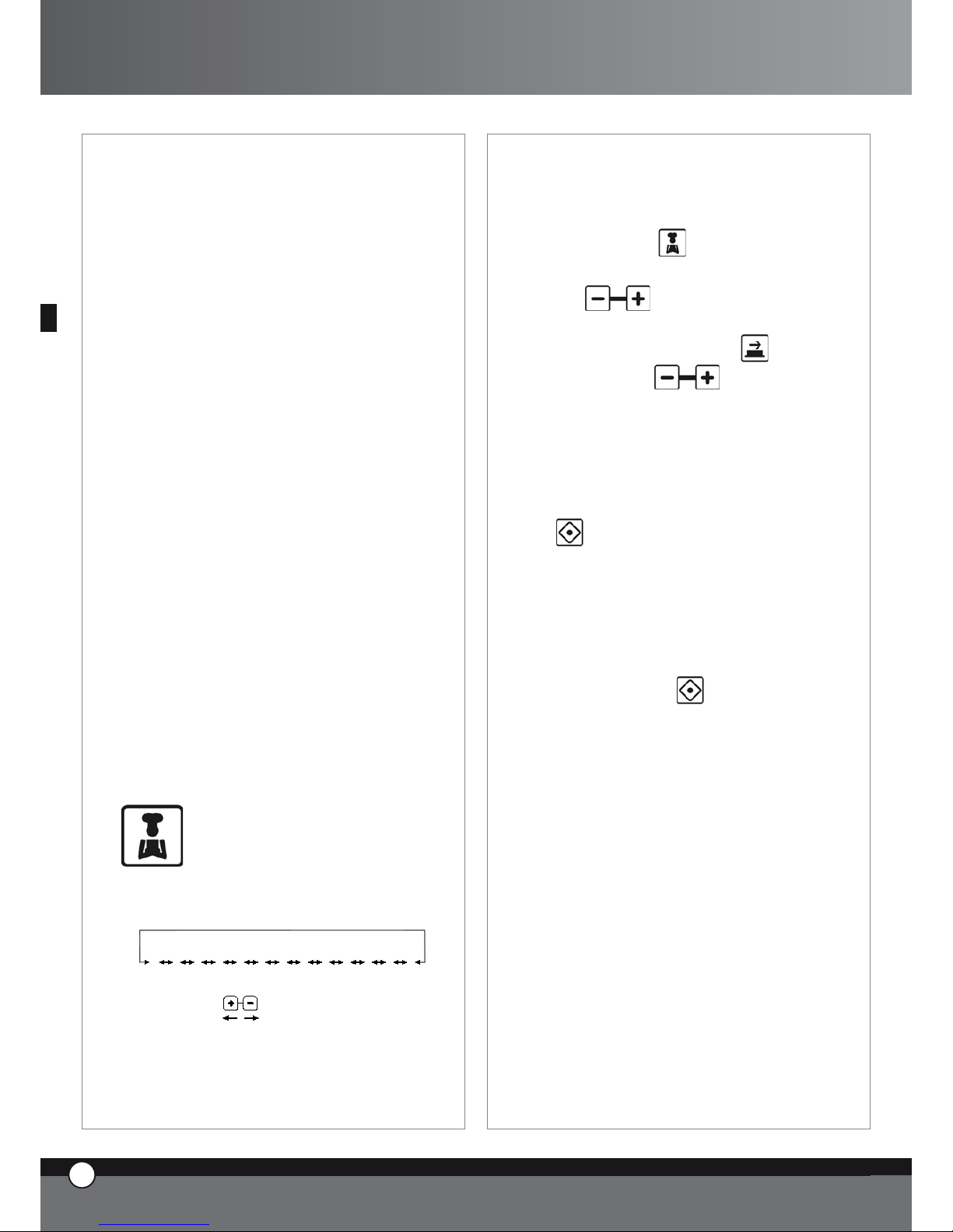
ture est maintenue, le four commence à émettre un signal sonore et les données relatives à la première phase
de cuisson apparaissent sur les afficheurs. Après avoir ouvert la porte, on met le produit à l’intérieur et on ferme la
porte. À ce point, l’exécution du programme de cuisson
commence automatiquement.
À la fin de chaque cycle de cuisson, que ce soit en modalité manuelle ou bien avec un programme, en pressant le
bouton “P” sur l’afficheur 5, on voit apparaitre inscription
“LASTP”:
en pressant le bouton “START / STOP” on fait partir de
nuoveau, le dernier cycle de cuisson qui a été exécuté.
Programmes de lavage
À l’intérieur du panneau de contrôle, 4 programmes de
lavages ont été stockés (L1 bref, L2 moyen, L3 long), un
programme de rinçage rapide (LH20) + le programme
de pré chargement des tubes (PUMP).
Programme de refroidissement chambre
de cuisson
“COOL”
Le programme de refroidissement de la chambre de cuisson “COOL” permet de refroidir la chambre de cuisson en
faisant fonctionner les turbines. Le programme fonctionne aussi avec la porte ouverte.
Durant tel programme, on voit est visualisée la température à l’intérieur de la chambre de cuisson.
N.B. Le carter protection turbines n’est pas amovible
sans l’utilisation d’un outil fait exprès grâce à une vis de
fixage. Au cas où on enlèverait le carter protection turbines pour la maintenance, faites attention que le four soit
débrancher électriquement.
3.7
CYCLES DE CUISSON “ChefUnox” -
“BakerUnox”
PIZZA
BREAD
BAKE
POLLO
FRIES
STEAM
STEAM PRB1
ROAST
GRILL
SLOW
VACUO
REGEN
PIZZA ITALY
Le contrôle électronique “ChefTouch” - “BakerTou-
ch” contient, dans sa propre mémoire, une série de
cycles de cuisson automatiques: en sélectionnant le cycle
de cuisson voulu, on a la possibilité de cuisiner automati-
quement une infinité de gamme d’aliments.
Dans chaque cycle de cuisson, on a la possibilité de modifier
quelques paramètres pour personnaliser le résultat attendu.
Pour extraire un programme pré introduit, procéder
comme suit :
Presser le bouton
Sélectionner le programme voulu au moyen des boutons
C’est possible modifier la valeur du paramètre qui
clignote en pressant le bouton et successivement les boutons
pour changer la valeur
du même paramètre (au cas où on voudrait rendre
cette modification effectuée permanente, il faut
presser le bouton pour 5 secondes (la mémorisation
est confirmée par le signal sonore)
Faire partir le programme au moyen du bouton
Le départ du programme est signalé par l’illumination
de l’indicateur “START / STOP”
Durant l’exécution du programme, modifier les paramètre de fonctionnement devient impossible
On peut interrompre l’exécution du programme en
pressant le bouton
CYCLES DE CUISSON AUTOMATIQUES
POUR FAMILLES DE PRODUITS
Cycle de cuisson “PIZZA ITALY”
Programme pour la cuisson des pizzas “minces”.
Paramètre variable: temps de cuisson.
On conseille d’utiliser la plaque “FAKIRO™” TG860
faite exprès par UNOX.
Cycle de cuisson “PIZZA”
Programme pour la cuisson des pizzas “épaisses”.
Paramètre variable: temps de cuisson.
Cycle de cuisson “PANE”
Programme pour la cuisson de pain et produits similaires
(type de pain).
Utiliser la sonde à cœur pour vérifier le degré de cuisson
•
•
•
•
•
•
•
7
FRANÇAIS
ChefTop™ - BakerTop™
Page 31

UNO
R
8
FRANÇAIS
du produit.
Paramètre variable: température à cœur pour obtenir un
produit plus ou moins cuit.
Cycle de cuisson “
BAKE”
Programme pour la cuisson des produits de pâtisserie
(type de pâtisserie).
Utiliser la sonde à cœur pour vérifier le degré de cuisson
du produit.
Paramètre variable: température à cœur pour obtenir un
produit plus ou moins cuit.
Cycle de cuisson “POLLO” (soulement pour ChefTop™)
Programme pour la cuisson du poulet / volailles en
général.
Paramètre variable: température à cœur pour obtenir un
produit plus ou moins cuit.
On conseille d’utiliser la grille “Pollo” GRP810 faite exprès par UNOX. Le cycle consiste dans un pré-réchauffement à 210 °C et en 4 phases où la température passe
de 180°C à 250°C.
Cycle de cuisson “FRIES” (soulement pour ChefTop™)
Programme pour la cuisson des pommes frittes.
Paramètre variable: temps de cuisson pour obtenir un
produit plus ou moins cuit.
On conseille d’utiliser la plaque “No Fry” GRP815 faite
exprès par UNOX.
CYCLES DE CUISSON AUTOMATIQUES
POUR TYPOLOGIE DE CUISSON
Cycle de régénération “REGEN” (soulement pour ChefTop™)
Un Cycle de régénération qui permet de régénérer des
produits cuits précédemment et conservés.
Paramètre variable: temps du processus de régénération.
Courbe Cycle de cuisson (disponible seulement si le kit
sonde à cœur externe XC240 est lié)
Programme pour la cuisson des aliments sous vide.
Paramètre variable: température à cœur pour s’adapter
aux différents types d’aliments.
L’utilisation de la sonde à cœur présente dans le Kit
XC240 ayant une pointe très fine vous évite de provoquer des déchirures aux sacs utilisés pour conserver les
aliments sous vide.
Cycle de cuisson “STEAM” (soulement pour ChefTop™)
Convenable pour la cuisson de viande, poisson, légumes
et pommes de terre à vapeur. Paramètre variable: temps
de cuisson pour obtenir un produit plus ou moins cuit.
Avec cette courbe, les turbines à l’intérieur de la chambre de cuisson tournent seulement dans le sens des aiguilles d’une montre (pas d’inversion de marche). donc,
l’inversion de marche ne vient pas exécutée. La quantité
d’eau introduite dans la chambre de cuisson change selon
la température introduite: en augmentant la température, la quantité d’eau diminue. C’est le four qui calcule
automatiquement la quantité correcte d’eau à introduire
en fonction de la température.
Cycle de cuisson STEAM PRB1 (disponible seulement si
le kit sonde à cœur externe XC240 est lié) (soulement
pour ChefTop™)
Ce cycle utilise la sonde à cœur externe.
Convenable pour la cuisson des produits délicats ou de
petites dimensions comme les ensachés, poisson et légumes à vapeur qui utilise la sonde à cœur externe pour
vérifier le degré de cuisson du produits.
Paramètre variable: température à cœur pour obtenir un
produit plus ou moins cuit.
Avec cette courbe, les turbines à l’intérieur de la chambre
de cuisson tournent seulement dans le sens des aiguilles
d’une montre (pas d’inversion de marche).
Cycle de cuisson “SLOW” (soulement pour ChefTop™)
Ce cycle utilise la sonde à cœur.
Convenable pour la cuisson lente à température basse.
Idéale pour les grandes pièces de viande.
Paramètre variable: température à cœur pour obtenir un
produit plus ou moins cuit; à la fin de la cuisson, maintenir
le produit à la température de 70 °C.
Cycle de cuisson “ROAST” (soulement pour ChefTop™)
Ce cycle utilise la sonde à cœur.
Convenable pour la cuisson des rôtis viandes et poissons.
Paramètre variable: température à cœur pour obtenir un
produit plus ou moins cuit.
On conseille d’utiliser la plaque “Black” TG835 faite
exprès par UNOX.
Cycle de cuisson “GRILL” (soulement pour ChefTop™)
Convenable pour griller viande et poisson.
Paramètre variable: température à cœur pour obtenir un
produit plus ou moins cuit.
On conseille d’utiliser la plaque “FAKIRO™ Grill”
TG845 faite exprès par UNOX.
Page 32

3.8
COMMANDE DE PLUSIEURS APPAREILS AU MOYEN DU MÊME CONTRÔLE
Le panneau de commandes digital ChefTouch BakerTouch permet di commander tous les équipe-
ments UNOX de la ligne ChefTop™ - BakerTop™
associés au four. L’introduction du système MASTER SLA-
VE vous permet en outre de gérer, avec un seul contrô-
le digital, plusieurs fours. Le four qu’on décide d’utiliser
pour commander tous les autres équipements devient le
four MASTER. Les fours commandés par le four MASTER
deviennent fours SLAVE avec le contrôle digital inactif.
Les contrôles digitaux MASTER et les contrôles digitaux
SLAVE sont , le cas échéant, interchangeables.
On sélectionne l’appareil qu’on doit contrôler au moyen
du bouton et l’appareil contrôlé, à ce point, est visualisé
sur l’afficheur 4.
Tableau de correspondance numéro – appareil
Numéro
appareil
Code
appareil
Dispositif
1
ChefTop™ Four
- master
2
ChefTop™ Four
- slave 2
3
ChefTop™ Four
- slave 3
4 XK304
Cellule de refroidissement
rapide
5 XL314
Cellule de maintien en
température
7 XC314 Hood
8 XC224
Système d’osmose
inverse
Numéro
appareil
Code
appareil
Dispositif
1
BakerTop™ Four
- master
2
BakerTop™ Four
- slave 2
3
BakerTop™ Four-
slave 3
5 XL 404
Étuve
7 XC 414 Hotte
8 XC224
Système d’osmose
inverse
En cas d’appareils montés en colonne, ce type de technologie permet de travailler en manière très ergonomique en utilisant toujours la même logique de fonctionnement.
4. LES PRINCIPES DE CUISSON
4.1 Les variables de cuisson
Temps
Cette variable dépend beaucoup de la quantité des aliments introduite dans le four. Les temps de
cuisson s’allongent quand les quantités augmentent et
vice-versa.
Des temps plus courts par rapport à ceux correctes ne
permettent pas une cuisson complète des
aliments. Des temps plus longs, toujours par rapport à
ceux correctes, créent des phénomènes de brûlure extérieure des aliments.
Température de la chambre de cuisson
l’exacte introduction de température garantit une cuisson
correcte des aliments que se soit dans la partie externe
ou bien dans la partie interne:
Une température basse par rapport à celle correcte
tend plus à dessécher qu’à cuire les aliments.
Une température supérieure à celle correcte tend à
brûler la partie extérieure et à laisser l’intérieur non
cuit (ce phénomène parfois est voulu par exemple
dans la cuisson de la viande).
Air chaud sec
Le système d’air chaud sec “DRY.Maxi™”, breveté par
UNOX, permet d’extraire de la chambre de cuisson, l’humidité produite par le produit alimentaire durant la cuisson en maintenant comme ça le milieu toujours sec. De
cette façon, le produit devient croquant et croustillant à
l’extérieur (ex. Pain, croissant), pendant qu’à l’intérieur, le
produit maintient une structure sèche et uniforme.
Vapeur
L’introduction de la variable vapeur (STEAM.Maxi™) et
ses différents combinaisons avec la température permet
d’effectuer des différents types de cuisson:
Cuissons à vapeur (seulement vapeur);
Cuissons mixte convection - vapeur (de l’air + de la
vapeur).
4.2 Les conseils du Chef pour des cuissons uniformes
Pré réchauffement
On conseille toujours de pré réchauffer le four à une
température supérieure par rapport à celle prévue pour
la cuisson d’au moins 30-50°C pour annuler les effets de
pertes de chaleur à l’ouverture de la porte.
•
•
•
•
9
FRANÇAIS
ChefTop™ - BakerTop™
Page 33

UNO
R
10
FRANÇAIS
Typologie de plaques
Pour obtenir une parfaite qualité de cuisson et pour rissoler les aliments uniformément, on conseille de na pas utiliser des récipients d’une hauteur très élevée parce qu’ils
interdisent la correcte circulation de l’air.
Espace entre plaques
Pour une cuisson uniforme, il est indispensable contrôler
l’espace entre le produit complètement levé et la plaque
supérieur. L’espace doit être au moins 3 cm
Charge de cuisson
Pour obtenir des meilleurs résultats, il est nécessaire
non pas surcharger le four et contrôler, en cas de pain
et pâtisserie, l’orientation du produit sur les plaques par
rapport au flux d’air.
Positionnement de la sonde à cœur
Pour un fonctionnement correcte de la sonde à cœur, il
faut l’insérer, en plongé vers le bas, dans le point le plus
épais de l’aliment jusqu’à rejoindre, avec la pointe de la
sonde, le centre de l’aliment. Au cas des aliments d’épaisseur réduite, la sonde doit être insérée horizontalement
au plan d’appui.
IMPORTANT!
Le four ventilé utilise des températures de 20-40°C inférieures à celles normalement utilisées dans les fours
statiques.
4.3 Cuisson à Convection
Température variable de 30°C à 260°C
La cuisson à convection se fait à travers la recirculation de
l’air chaud et sec à l’intérieur de la chambre de cuisson.
Cette recirculation a été étudiée pour pouvoir distribuer
d’une manière homogène la chaleur et comme ça, elle
garantit une cuisson uniforme des aliments dans leurs superficies et à l’intérieur, même si le four est complètement chargé.
Convenable pour: les Cuissons au gratin, les Cuissons des
rôtis et les Cuissons à la grille
Les Avantages: la possibilité de cuisiner en même temps des
aliments de nature différentes, comme les légumes, la viande, le poisson, lesquels exigent la même température, sans
mélanger les saveurs.
La cuisson à convection se fait à travers la recirculation de
l’air chaud et sec à l’intérieur de la chambre de cuisson.
Cette recirculation a été étudiée pour pouvoir distribuer
d’une manière homogène la chaleur et comme ça, elle
garantit une cuisson uniforme des aliments dans leurs superficies et à l’intérieur, même si le four est complètement chargé.
4.4 Cuisson Mixte à Convection + Vapeur
Température variable de 30°C à 260°C
Vapeur variable de 30% à 90%
Il s’agit d’une cuisson qui prévoit l’utilisation combinée
d’air chaud sec e de vapeur distribués d’une manière
homogène à l’intérieur de la chambre de cuisson et
elle représente le système de travail le plus favorisé et
le plus efficace parmi les méthodes de cuisson utilisées
aujourd’hui. Les temps de travail se réduisent d’une façon
remarquable et, au même temps, les produits alimentaires maintiennent leur poids presque inchangé et restent
plus tendres.
Convenable pour:
• Cuissons des Rôtis, Roastbeef, Ragoûts
• Cuissons des Poissons
Les conseils du Chef:
Pour la cuisson des rôtis, le Chef conseille d’utiliser un plaque
perforée ou bien une grille puisque comme ça, on n’a plus
besoin de tourner les aliments en continuation. On peut récolter les jus de la viande en ajoutant sur le fond de la chambre de cuisson, une claque non perforée avec à son intérieur
des aromes et des mirepoix de légumes (céleri, carottes, oignons) qui peuvent servir après à préparer une magnifique
sauce pour le plat qu’on doit servir.
4.5 Cuisson à Vapeur
Cuisson à vapeur à basse température de 48°C à 130°C
Vapeur: 100%
L’utilisation de la cuisson à vapeur, supportée par la turbines, est parmi les méthodes les plus délicates pour cuisiner les aliments. Avec ce type de cuisson, les aliments
ne perdent pas leur liquide et maintiennent leur contenu
nutritionnel, leur saveur, leur aspect externe et leur poids
inaltérables.
Convenable pour:
Cuissons à vapeur à basse température: Légumes,
Fruits, Terrines, Soufflé, Pâté, Cuissons sous vide
Cuissons à vapeur: Légumes, Fruits, Œufs, Viande,
Poisson
Cuissons à vapeur poussée: Pommes de terre
Les conseils du Chef:
Pour la cuisson à vapeur des légumes à feuille, on conseille
baigner préventivement les aliments pour éviter le séchage initial. Pour éviter, par contre, la dispersion du produit à
cause des flux d’air à l’intérieur de la chambre de cuisson,
utiliser 2 grilles No Fry, une come base pour la cuisson et
l’autre renversée comme couvercle.
•
•
•
Page 34

4.6 Cuisson à Convection
Température variable de 30°C à 260°C
La cuisson à convection se fait à travers la recirculation
de l’air chaud et sec à l’intérieur de la chambre de cuisson.
Cette recirculation a été étudiée pour pouvoir distribuer
d’une manière homogène la température et garantir de
cette façon une cuisson uniforme du produit sur toute
la surface de la plaque et sur toutes les plaques, même si
le four est complètement chargé. La pâtisserie est cuite
parfaitement de l’extérieur avec un dorage homogène et
aussi à son intérieur en donnant au produit une structure
uniforme et une humidité restante constante.
Convenable pour:
Cuissons de Pâte brisée, Pâte feuilletée, Pâte à
choux
Cuissons de Génoise
Cuissons de Biscuits
Les conseils du Chef:
Pour obtenir un résultat optimal dans les cuissons de la
pâtisserie, il est nécessaire avoir une distance majeure entre
les plaques et une distance majeur du produit sur la plaque.
Pour les produits particulièrement légers, on vous conseille
d’utiliser le Kit de réduction de soufflerie pour éviter qu’ils
se déplacent sur la plaque.
4.7 Cuisson à Convection + Humidité
Température variable de 30°C à 260°C
Humidité variable de 10% à 20%
Ce système utilise l’air chaud comme moyen de cuisson
avec l’ajout d’humidité variable selon le produit qu’on
doit cuisiner.
Convenable pour:
Cuissons de Pates levées comme la Pain
Cuissons des Gâteaux Colombe, Panettone, Croissants, Brioches.
Les conseils du Chef:
L’utilisation de vapeur, au commencement de la cuisson, facilite le levage du produit, successivement cette vapeur peut
être réduits ou bien totalement éliminée, pour obtenir le dorage et l’effet coquant voulus.
4.8 Cuisson à Convection + Air sec
Système “DRY.Maxi™” (Brevet Mondial UNOX)
Température variable de 30°C à 260°C
Air sec de 10% à 100%
Il s’agit d’un système complètement nouveau qui permet
d’extraire de la chambre de cuisson l’humidité générée
•
•
•
•
•
par la produit durant la cuisson en maintenant de cette
façon un milieu toujours sec.
Le produit se présente croquant et croustillant grâce à
son intérieur sec et sa structure uniforme.
Convenable pour:
• Cuissons des Croissants, Brioches
• Cuissons des Biscuits
• Cuisson de Pain
4.9 Cuisson avec la Sonde à Cœur + Température
chambre de cuisson
Ce type de cuisson prévoit l’introduction de la température à cœur et de la température dans la chambre de
cuisson. La sonde à cœur relève l’augmentation de température à l’intérieur du produit durant tout le processus
de cuisson et elle doit être insérer dans le point le plus
épais du produit et avec la pointe au centre de ce produit.
Avec ce système, l’introduction de la variable Temps n’est
plus nécessaire; le four, en effet, s’éteindra automatiquement à l’atteinte de la température à cœur précédemment introduite ou il passera à la phase de cuisson successive en cas d’un programme.
Ce système est utile pour optimiser la cuisson des différents produits alimentaires en évitant de les contrôler
durant toutes les phases de cuissons.
4.10 Cuisson avec la Sonde à Cœur + Delta T
Dans ce type de cuisson, on introduit la température
qu’on veut atteindre au cœur du produit et le delta T (la
différence entre la température à cœur et la température
dans la chambre de cuisson).
Core probe + 100°C ∆T
Sonda al cuore + ∆T a 100°C
Sonde à cœur + température de
l’enceinte
Enceinte de cuisson
Temps en minutes
Température
Température à cœur programmée
C
œ
u
r
d
u
p
r
o
d
u
i
t
TEMPÉRATURE CHAMBRE DE CUISSON = TEM-
PÉRATURE À CŒUR + DELTA T INTRODUIT
De cette façon, la température dans la chambre de cuisson augmentera graduellement en maintenant inchangé
Chef-
11
FRANÇAIS
ChefTop™ - BakerTop™
Page 35
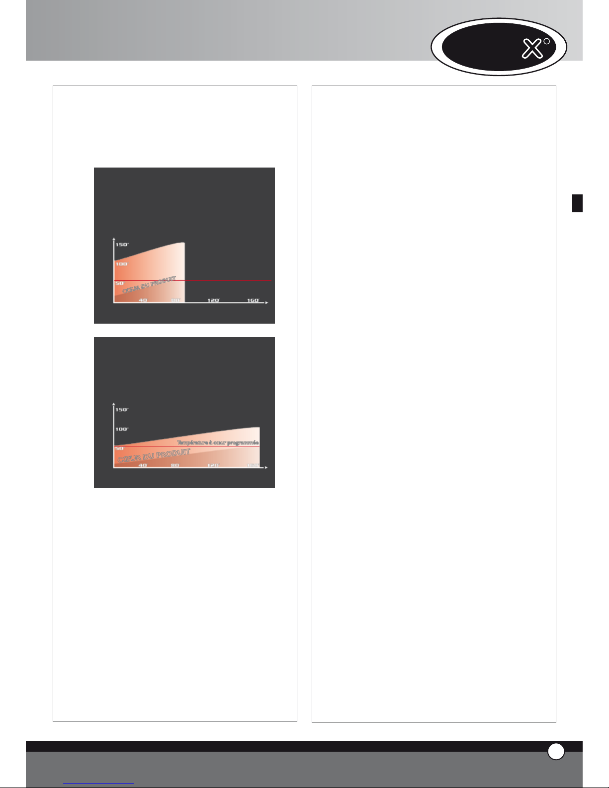
12
FRANÇAIS
et pour toute la durée de cuisson, la différence entre la
température au cœur du produit et la température dans
la chambre de cuisson que vous avez introduit au début.
Ce type de cuisson vous permet de faire des cuissons très
douces et délicates, particulièrement indiquées pour les
grandes pièces de viandes
Sonde à cœur + ∆T à 100°
E
N
C
E
I
N
T
E
D
E
C
U
I
S
S
O
N
Température à cœur programmée
C
Œ
U
R
D
U
P
R
O
D
U
I
T
Temps en minutes
Température
Sonde à cœur + ∆T à 50°
C
Œ
U
R
D
U
P
R
O
D
U
I
T
E
N
C
E
I
N
T
E
D
E
C
U
I
S
S
O
N
Température à cœur programmée
Temps en minutes
Température
5. COMMUNICATION AVEC LE MONDE
EXTERNE
Le panneau de commandes digital des fours ChefTop™
- BakerTop™ a été prédisposé pour faire dialoguer
facilement le four avec le monde externe à travers des
systèmes de communication présents et futures. USB,
Bluetooth, sériel etc.
Le Kit d’interface USB, code XC226 est maintenant disponible; il vous permet de d’exercer les fonctions suivantes:
Introduction des programmes de cuisson
Modification des paramètres opératifs (ex. tarage des
sondes)
Diagnostic des disfonctionnements
Mémorisation de l’évolution des températures à
•
•
•
•
l’intérieur de la chambre de cuisson du four et de la
chambre de cellule de refroidissement rapide (données nécessaire pour le système « HACCP » méthode
et principes de gestion de la sécurité sanitaire des aliments)
Connexion à une imprimante (HACCP)
Des ultérieures informations sont présentes à
l’intérieur du Kit.
6. MAINTENANCE ORDINAIRE
Toutes les opérations de maintenance doivent être effectuées uniquement par un personnel d’entretien qualifié.
Avant d’effectuer n’importe quel type de maintenance,
il faut débrancher l’alimentation électrique et attendre le
refroidissement de l’équipement.
Il faut soumettre l’équipement périodiquement (au moins
une fois par an) à un contrôle total de la part d’un technicien spécialisé.
6.1 SUBSTITUTION AMPOULE D’ÉCLAIRAGE
Pour substituer l’ampoule d’éclairage, il faut faire comme suit:
Débranche électriquement l’équipement et le laisser
refroidir
Enlever le grilles latérales
Dévisser le couche-ampoule en verre et substituer
l’ampoule par une autre ayant les mêmes caractéristiques.
Revisser le cache-ampoule en verre
Remonter les grilles latérales
7. MAINTENANCE EXTRAORDINAIRE
Toutes les opérations de maintenance doivent être effectuées uniquement par un personnel d’entretien qualifié.
Avant d’effectuer n’importe quel type de maintenance,
il faut débrancher l’alimentation électrique et attendre le
refroidissement de l’équipement.
Les composantes qui nécessitent la maintenance, sont accessibles en enlevant le panneau postérieur du four.
7.1 RÉARMEMENT DU DISPOSITIF THERMIQUE DE
SÉCURITÉ
L’équipement est doté d’un dispositif thermique d’interruption à réarmement manuel pour la protection contre
les sur-températures. Au cas où ce dispositif intervient, il coupe l’alimentation aux résistances : à ce point, le message EF4
apparait sur le display 2.
Tel dispositif est accessible en enlevant le bouchon noir
positionné en bas dans le côté postérieur de l’équipement: en cas de réarmement manuel, presser le bouton
au centre du dispositif pour réactiver l’équipement.
•
•
•
•
•
•
•
UNO
R
Page 36

9. LES PANNES PLUS FRÉQUENTES
PANNE CAUSE SOLUTION
Manque de tension du réseau
électrique
Rétablir la tension d’alimentation
Intervention d’un des fusibles
présents sur la fiche de puissance
S’adresser à un technicien
spécialisé pour la réparation
Le four est complètement éteint
Branchement au réseau électrique
fait incorrectement
Vérifier le branchement au réseau
électrique
Entrée de l’eau fermée Ouvrir l’entrée de l’eau
Raccordement au réseau hydrique
ou au réservoir fait
incorrectement
Vérifier le raccordement au
réseau hydrique ou au réservoir
Absence d’eau dans le réservoir
(au cas du chargement d’eau du
réservoir)
Introduire de l’eau dans le
réservoir
L’émission d’humidité
dans la chambre de
cuisson est activée mais
l’eau ne sort pas à
travers les tuyaux
Le Filtre d’entrée de
l’eau est bouché par des
impuretés
Nettoyer le filtre
Porte ouverte ou ferme
incorrectement
Fermer la porte correctement
Après avoir établi temps ou
température à cœur et avoir
pressé le bouton STAR / STOP le
four ne part pas
Interrupteur magnétique
endommagé
S’adresser à un technicien
spécialisé pour la réparation
Joint endommagé
S’adresser à un technicien
spécialisé pour la réparationAvec la porte fermée, l’eau
s’échappe à travers le joint
Mécanisme de la poignée détendu
S’adresser à un technicien
spécialisé pour la réparation
Ampoule grillée Substituer l’ampoule
Lumière du four éteinte
Ampoule détendue
Insérer correctement l’ampoule
dans le porte-ampoule
Les turbines n’effectuent pas
l’inversion de marche
S’adresser à un technicien
spécialisé pour la réparation
Une des turbines est au repos (en
cas de four avec plusieurs
moteurs)
S’adresser à un technicien
spécialisé pour la réparation
Le four ne cuisine pas en manière
uniforme
Une des résistances cassée
S’adresser à un technicien
spécialisé pour la réparation
13
FRANÇAIS
ChefTop™ - BakerTop™
s’adresser au personnel qualifié pour l’exécution des relatifs
contrôles.
9. COUPURE EN CAS DE PANNE
En cas de panne, désactiver l’équipement :
débrancher l’interrupteur automatique
d’alimentation électrique qui alimente l’appareil.
s’adresser au centre d’assistance technique UNOX
plus proche.
•
•
Page 37

UNO
R
14
FRANÇAIS
10. MESSAGES D’ERREURS
10.1 MESSAGES D’ERREURS DU FOUR
PANNE CAUSE SOLUTION
Fils de liaison de la sonde de
chambre 1 détachés de la fiche de
puissance
S’adresser à un technicien
spécialisé pour la réparation
Sonde de chambre 1
endommagée
S’adresser à un technicien
spécialisé pour la réparation
Sur l’afficheur digital 1, l’écriture
EF1 apparaît constamment
Fiche de puissance du four
endommagée
S’adresser à un technicien
spécialisé pour la réparation
Fils de liaison de la sonde de
chambre 2 détachés de la fiche de
puissance
S’adresser à un technicien
spécialisé pour la réparation
Sonde de chambre 2
endommagée
S’adresser à un technicien
spécialisé pour la réparation
Sur l’afficheur digital 1, l’écriture
EF2 apparaît constamment
Fiche de puissance du four
endommagée
S’adresser à un technicien
spécialisé pour la réparation
Fils de liaison de la sonde de à
cœur détachés de la fiche de
puissance
S’adresser à un technicien
spécialisé pour la réparation
Sonde à cœur endommagée
S’adresser à un technicien
spécialisé pour la réparation
Sur l’afficheur digital 1, l’écriture
EF3 apparaît constamment
Fiche de puissance du four
endommagée
S’adresser à un technicien
spécialisé pour la réparation
Intervention du protecteur
thermique d’un moteur
Couper la tension au four,
attendre son refroidissement et
fournir de nouveau la tension: si
l’écriture EF4 apparaît de
nouveau, s’adresser à un
technicien spécialisé pour la
réparation
Sur l’afficheur digital 1, l’écriture
EF4 apparaît constamment
Fiche de puissance du four
endommagée
S’adresser à un technicien
spécialisé pour la réparation
Intervention du dispositif
thermique de sécurité
Couper la tension au four,
attendre son refroidissement,
rétablir le dispositif thermique et
fournir la tension de nouveau: si
l’écriture EF4 apparaît de
nouveau, s’adresser à un
technicien spécialisé pour la
réparation
Sur l’afficheur digital 1, l’écriture
EF5 apparaît constamment
Fiche de puissance du four
endommagée
S’adresser à un technicien
spécialisé pour la réparation
Câble de liaison tableau de
commandes / fiche de puissance
endommagé ou détaché
Sur l’afficheur digital 1, l’écriture
EF6 apparaît constamment
Fiche de puissance du four
endommagée
S’adresser à un technicien
spécialisé pour la réparation
Sur l’afficheur digital 1, l’écriture
EF7 apparaît constamment
Perte de communication entre le
four et les accessoires.
S’adresser à un technicien
spécialisé pour la réparation
Page 38

10.2 MESSAGES D’ERREURS CELLULE DE REFROIDISSEMENT RAPIDE
PANNE CAUSE SOLUTION
Fils de liaison de la sonde de
chambre détachés de la fiche de
puissance
S’adresser à un technicien
spécialisé pour la réparation
Sonde chambre de cuisson
endommagée
S’adresser à un technicien
spécialisé pour la réparation
Sur l’afficheur digital 1, l’écriture
EA1 apparaît constamment
Fiche de puissance cellule de
refroidissement rapide
endommagée
S’adresser à un technicien
spécialisé pour la réparation
Fils de liaison de la sonde de à
cœur détachés de la fiche de
puissance
S’adresser à un technicien
spécialisé pour la réparation
Sonde à cœur endommagée
S’adresser à un technicien
spécialisé pour la réparation
Sur l’afficheur digital 1, l’écriture
EA2 apparaît constamment
Fiche de puissance cellule de
refroidissement rapide
endommagée
S’adresser à un technicien
spécialisé pour la réparation
Surpression circuit réfrigérateur
Couper la tension à la cellule de
refroidissement, attendre une
vingtaine de minutes set fournir
de nouveau la tension: si l’écriture
EA3 apparaît de nouveau,
s’adresser à un technicien
spécialisé pour la réparation
Sur l’afficheur digital 1, l’écriture
EA3 apparaît constamment
Fiche de puissance cellule de
refroidissement rapide
endommagée
S’adresser à un technicien
spécialisé pour la réparation
Sur l’afficheur digital 1, l’écriture
EA4 apparaît constamment
Limite fonctionnement des filtres Il faut enlever le filtre et le laver
Câble de liaison four / Cellule de
refroidissement rapide
endommagé ou détaché
Sur l’afficheur digital 1, l’écriture
EA5 apparaît constamment
Fiche de puissance cellule de
refroidissement rapide
endommagée
S’adresser à un technicien
spécialisé pour la réparation
10.3 MESSAGES D’ERREURS CELLULE DE MAINTIEN EN TEMPERATURE
PANNE CAUSE SOLUTION
Fils de liaison de la sonde de
chambre détachés de la fiche de
puissance
S’adresser à un technicien
spécialisé pour la réparation
Sonde de chambre endommagée
S’adresser à un technicien
spécialisé pour la réparation
Sur l’afficheur digital 1, l’écriture
EL1 apparaît constamment
Fiche de puissance cellule de
maintien endommagée
S’adresser à un technicien
spécialisé pour la réparation
Fils de liaison de la sonde humidité
détachés de la fiche de puissance
S’adresser à un technicien
spécialisé pour la réparation
Sonde d’humidité endommagée
S’adresser à un technicien
spécialisé pour la réparation
Sur l’afficheur digital 1, l’écriture
EL2 apparaît constamment
Fiche de puissance cellule de
maintien endommagée
S’adresser à un technicien
spécialisé pour la réparation
Câble de liaison four / Cellule de
maintien en tp endommagé ou
détaché
Sur l’afficheur digital 1, l’écriture
EL3 apparaît constamment
Fiche de puissance cellule de
Maintien en tp
endommagée
S’adresser à un technicien
spécialisé pour la réparation
15
FRANÇAIS
ChefTop™ - BakerTop™
Page 39

UNO
R
16
FRANÇAIS
10.4 MESSAGES D’ERREURS HOTTE
PANNE CAUSE SOLUTION
Fils de liaison de la sonde de
température détachés de la fiche
de puissance
S’adresser à un technicien
spécialisé pour la réparation
Sonde de température
endommagée
S’adresser à un technicien
spécialisé pour la réparation
Sur l’afficheur digital 1, l’écriture
EC1 apparaît constamment
Fiche de puissance hotte
endommagée
S’adresser à un technicien
spécialisé pour la réparation
Câble de liaison four / Hotte
endommagé ou détaché
Sur l’afficheur digital 1, l’écriture
EC2 apparaît constamment
Fiche de puissance Hotte
endommagée
S’adresser à un technicien
spécialisé pour la réparation
10.5 MESSAGES D’ERREURS SYSTEME D’OSMOSES
PANNE CAUSE SOLUTION
Trasducteur de pression
endommagé
Câble de liaison trasducteur / fiche
endommagé ou détaché
Sur l’afficheur digital 1, l’écriture
EO1 apparaît constamment
Fiche de puissance Osmose
Inverse endommagée
S’adresser à un technicien
spécialisé pour la réparation
Compte-litres endommagé
Câble de liaison compte-litres /
fiche endommagé ou détaché
Sur l’afficheur digital 1, l’écriture
EO2 apparaît constamment
Fiche de puissance Osmose
endommagée
S’adresser à un technicien
spécialisé pour la réparation
Sur l’afficheur digital 1, l’écriture
EO3 apparaît constamment
Limite du fonctionnement des
filtres
S’adresser à un technicien
spécialisé pour la réparation
Sur l’afficheur digital 1, l’écriture
EO4 apparaît constamment
Pression d’eau en entrée très
basse
Verifier que l’eau arrive à l’entrée
de système d’Osmose
Câble de liaison four / Osmose
endommagé
ou détaché
Sur l’afficheur digital 1, l’écriture
EO5 apparaît constamment
Fiche de puissance Osmose
Inverse endommagée
S’adresser à un technicien
spécialisé pour la réparation
Page 40

B INSTRUCTIONS POUR
L’INSTALLATEUR
1. AVERTISSEMENTS
Toutes les opérations d’installation, de montage, d’assistance et de maintenance doivent être faites par un
personnel techniquement qualifié selon les normes en
vigueur.
Prière de lire attentivement le notice d’utilisation avant
l’installation et la mise en service de l’appareil.
Prière de vérifier l’intégrité de l’appareil (contrôler les
éventuels dommages de transport). Enlever de la chambre de cuisson tout le matériel informatif.
2 OPÉRATIONS PRÉLIMINAIRES
2.1 LIEU D’INSTALLATION
Avant de positionner l’appareil, vérifier les mesures d’encombrement et l’exacte position des branchements et
des raccordements électriques, hydriques, évacuation fumées selon les figures rapportées dans l’annexe, chapitre
“Données techniques”.
2.2 PRÉDISPOSITION POUR LE POSITIONNEMENT
Les pieds sont mis à l’intérieur du four et doivent être
formellement montés.
Ne pas utiliser l’appareil sans les pieds montés.
Enlever le bac récolte gouttes du dos de four en utilisant
une tournevis.
Positionner le four sur un flanc.
Insérer les pieds selon les positions indiquées et les glissières du bac récolte gouttes comme indiqué dans la figure.
2.3 ENLÈVEMENT DE LA PELLICULE DE PROTECTION DU FOUR
Enlever attentivement et complètement la pellicule de
protection qui couvre les parties externes du four en
évitant de laisser des résidus de colle. Si malgré ça ces
résidus persistent, il faut les enlever avec un solvant convenable.
Enlever aussi la protection de la pointe de la sonde à
cœur.
2.4 POSITIONNEMENT
Positionner l’appareil en respectant les normes de sécurité indiquées comme suit:
Positionner l’appareil en mode que les parties postérieures soient facilement accessibles pour effectuer le branchement électrique et pour permettre la maintenance de
l’appareil.
17
FRANÇAIS
ChefTop™ - BakerTop™
Page 41

UNO
R
18
FRANÇAIS
Le four n’est pas encastrable parmi des autres appareils.
On vous conseille de laisser une distance de 5 cm tout
autour de l’appareil.
En se référent particulièrement aux fours, tous les modèles doivent être placés sur un support, par exemple une
étuve, un support porte-plaques ou bien sur une table.
Ne jamais installer les fours sur le sol directement.
Si l’appareil est positionné à côté d’un mur, diviseurs,
meubles de cuisine, bordures décorées etc., on vous recommande que ceux-ci soient faites d’un matériel incombustible.
En cas contraire ils doivent être revêtus par un matériel
isolant thermique incombustible, et il faut prêter une
grande attention aux règles de prévention incendies.
Ne pas installer l’appareil dans les proximités d’une friteuse.
Vérifier que l’appareil soit installer à plat.
3. BRANCHEMENT ELECTRIQUE
3.1 AVERTISSEMENTS
Le branchement au réseau électrique doit être effectué
selon les normatives en vigueur.
Avant d’effectuer le branchement, contrôler que la tension et la fréquence correspondent aux données présentent sur l’étiquette posée sur l’appareil.
L’appareil doit être positionné de sorte que la fiche de
connexion au réseau, soit accessible
(pour les appareils dotés de fiches Schuko).
Interposer entre l’appareil et le réseau, un interrupteur
omnipolaire accessible après l’installation, ayant des
contacts avec une distance d’ouverture minimum de 3
mm, de portée appropriée (par ex. :interrupteur magnétothermique).
On vous conseille l’emploi d’un interrupteur de sécurité
pour panne de réseau.
La tension d’alimentation, lorsque l’appareil est en fonction, ne doit pas s’écarter de la valeur nominale de la
tension rapportée sur l’étiquette données du four, de
±10%.
3.2 BRANCHEMENT AU RESEAU D’ALIMENTATION
ELECTRIQUE
1- Pour les fours dotés de câble et fiche Schuko (mo-
nophasé 230V): c’est suffisant insérer la fiche dans la
prise appropriée (la prise doit être indiquée pour la
fiche fournie en dotation).
2- Pour les fours dotés de câble (triphasé 400V + Neu-
tre) : ces fours sont dotés d’un câble électrique à 5
conducteurs : il est nécessaire relier le câble au tableau électrique. Pour effectuer les autres types de
connexion prévus, il est nécessaire substituer le câble.
Voir l’annexe « Données techniques » pour l’emploi
des câbles convenables. Les schémas de connexion se
trouvent dans la partie interne du cache plaque à bornes.
La substitution du câble doit être effectuée par un personnel autorisé.
Pour substituer le câble d’alimentation, procéder comme
suit:
Ouvrir le cache plaque à bornes en dévissant la vis de
fixage
Raccorder les conducteurs selon le schéma de
branchement choisi
Fixer le câble à l’aide de fixe câble convenable
Fermer le cache plaque à bornes et serrer la vis de
fixage
AVVERTISSEMENT:
Effectuer la connexion électrique de la plaque à bornes
comme indiqué dans le dessin: introduire
le pont de cuivre et le câble électrique ensemble sous la
vis, dans le sens de vissage, en manière que, en serrant la
•
•
•
•
Page 42

vis, le câble et le pont soient strictement fixés.
Une connexion incorrecte peut causer la surchauffe de la
plaque à bornes, jusqu’au point de la faire fondre.
L’appareil doit être branché à la ligne de terre du réseau.
3.3 BRANCHEMENT EQUIPOTENTIEL
L’appareil doit être inclus dans un système équipotentiel
d’une efficacité opportunément vérifiée selon les normatives en vigueur. Ce branchement doit être effectuer
entre des différents équipements avec la borne ayant le
symbole :
Le conducteur équipotentiel doit avoir une section minimum de 10 mm².
4. RACCORDEMENT HYDRIQUE
4.1 AVERTISSEMENTS
Il est nécessaire d’interposer entre le réseau hydrique et
le four un robinet d’interception et un
filtre mécanique.
L’appareil est fourni avec 2 mètres de tube et son raccord
relatif (3/4”) avec un clapet de non-retour et un filtre mécanique comme les normes en vigueur exigent. Avant de
relier le tube d’eau à l’appareil, faire découler de l’eau
pour éliminer les éventuels résidus. L’eau en entrée doit
avoir une valeur de pression comprise entre 1 et 3 bar et
une température maximum de 30°C.
4.2 TRAITEMENT DE L’EAU
L’eau doit avoir une dureté maximum de 5 °F (c’est pour
réduire la formation de calcaire à l’intérieur de la chambre de cuisson).
On vous conseille vivement l’emploi d’un appareil déminéralizateur (osmose inverse) pour éviter le dépôt calcaire et/ou des autres minéraux à l’intérieur du four. À ce
propos, on a mis à Votre disposition le système d’osmose
inverse UNOX code XC224 directement commandé par
un système d’autodiagnostic à travers le panneau de commandes (le contrôle électronique) du four.
5. RACCORDEMENT EVACUATIONS
5.1 AVERTISSEMENTS
L’eau en sortie de tube d’évacuation du four peut rejoindre
des températures élevées (90 °C).
Les tubes utilisés pour l’évacuation de l’eau doivent être
en mesure de supporter des telles températures.
5.2 EVACUATION DE L’EAU
Le tube d’évacuation de l’eau se trouve dans la partie postérieure du four et doit être relié avec un tube rigide
ou flexible et canalisé à une évacuation ouverte ou à siphon; son diamètre ne doit pas être inférieur à celui de
l’embout de déchargement et la longueur ne doit pas être
supérieure à un mètre.
Éviter les étranglements sur les conduites flexibles ou
bien les coudes pour les conduites métalliques, tout au
long du parcours d’évacuation.
Le tube d’évacuation doit rester au dessous de l’attaque
d’évacuation, d’au moins 20 cm, pour faciliter l’écoulement.
5.3 EVACUATION FUMEES CHAMBRE DE CUSISSON
Le tube d’échappement de fumées qui proviennent de la
chambre de cuisson, se trouve dans la
partie postérieure du four, en haut.
Ne pas superposer des objets et/ou des matériels sur le
tube d’échappement des fumées pour pouvoir garantir la
normale évacuation des fumées. Vérifier bien qu’au dessus de tube d’échappement fumées, aucun objet et/ou
matériel qui peut être endommagé des fumées mêmes,
soit présent.
On vous conseille, par conséquent, de positionner le four
au-dessous d’une hotte d’aspiration ou bien d’installer la
hotte d’aspiration UNOX code XC314 pour ChefTop™
- XC414 pour BakerTop™ ou le condenseur de vapeur
UNOX code XC114 ou bien de toute façon, d’acheminer
les fumées au moyen de tube UNOX code TB1520A0 en
évitant les étranglements.
19
FRANÇAIS
ChefTop™ - BakerTop™
Page 43

UNO
R
20
FRANÇAIS
6. LIAISON DES ACCESSOIRES (ETUVE,
HOTTE, CELLULE LIEVITATORE, CAPPA,
CELLULE DE REFROIDISSEMENT RAP
-
IDE, ETC…)
Le panneau de commandes du four contrôle tous les accessoires
(hotte, cellule de maintien en température, cellule de refroidissement rapide, système d’osmose).
Les accessoires liés au four, sont raccordés au four même à travers les connecteurs RJ45 posés derrière le four.
Pour raccorder les câbles, procéder comme suit:
Enlever le couvercle de protection en dévissant la vis
Insérer le connecteur du câble dans le convenable connecteur femelle présent sur la
fiche de puissance (aucune importance pour
quel connecteur des 3 présents vous utilisez)
Remonter le couvercle de protection en serrant la vis
Comme ça, l’accessoire est reconnu et lié au four.
Pour le fonctionnement et l’utilisation des accessoires,
voir le manuel d’instructions de l’accessoire en question.
•
•
•
7 SUBSTITUTION VERRES PORTE
7.1 AVERTISSEMENT
Le verre interne, par lequel la porte est constituée, est un
verre tempéré bas émissif. Une des surfaces de ce verre,
en fait, est couverte d’une pellicule métallique transparente qui limite le passage de chaleur dans l’interstice entre les 2 verres de la porte et le reflète à l’intérieur de la
chambre de cuisson..
La substitution du verre doit être effectuée en tenant en
considération cette caractéristique, c.à.d la surface basémissive devra être orientée vers la chambre de cuisson.
En cas contraire, on aura une augmentation de la tempéra-
ture de surface externe de la porte qui augmente le risque des brulures pour l’utilisateur ou bien de l’éclatement
de verre même
Le contrôle doit être effectué à l’aide d’un tester mis à
une portée maximale de KOhm. En appuyant les embouts
sur la surface de verre, à une distance d’environ 5 cm, le
coté bas missi résultera avec une résistance d’environ 50
Ohm, pendant que sur l’autre coté, le tester indiquera
une résistance infinie.
7. SUPERPOSITION DES FOURS
En cas d’une superposition de plusieures fours, l’utilisation des Kit de superposition UNOX code XC680 pour
ChefTop™ - XC 681 pour BakerTop™ est obligatoire, surtout pour maintenir la correcte distance entre 2
fours.
Le Kit pour la liaison d’alimentation de l’eau, eau d’évacuation et évacuation fumées, est aussi à votre disposition
XC615
Page 44
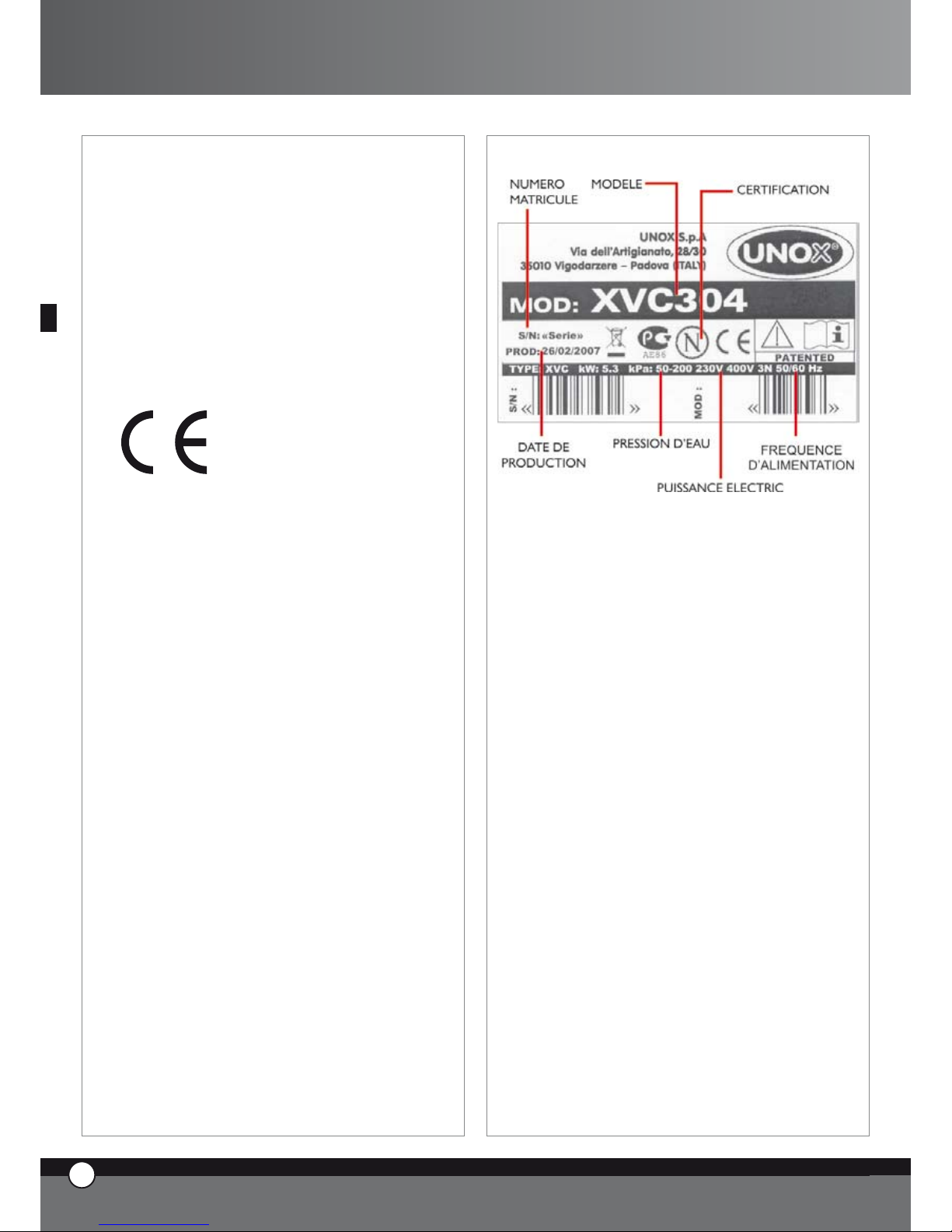
PLAQUE SIGNALETIQUE
13
ENGLISH
21
FRANÇAIS
C. CERTIFICATIONS
Constructeur: UNOX S.p.A.
Adresse: Via Dell’Artigianato 28/30
I-35010 Vigodarzere, Padova, Italy
Produit: Four ventilé à convection vapeur pour
utilisations professionnelles
Famille: ChefTop™ - BakerTop™
NORMATIVES DE REFERENCE
Le marquage “CE” reporté sur les équipements insérés
dans ce Manuel a comme référence les suivantes directives:
FOURS COMBINÉS À CONVECTION VAPEUR
ÉLECTRIQUES – SÉRIE XVC - XBC :
Directive Basse Tension 2006/95/CE selon les normes:
EN 60335-2-42:2003
EN 60335-1:2002; A11; A1; A12 ; A2 including possible listed national conditions/deviations for Norway.
Directive Compatibilité Électromagnétique 2004/108/CE
selon les normes:
EN 55014-1:2000; A1; A2
EN 61000-3-2:2000; A2
EN 61000-3-3:1995; A1; A2
EN 61000-3-11:2000
EN 55014-2:1997; A1
EN 50366:2003 ; A1
•
•
•
•
•
•
•
•
ChefTop™ - BakerTop™
Page 45

14
ENGLISH
UNO
R
22
FRANÇAIS
Bakertop™
ChefTop
™
www.unox.com
www.unox.com
BakerTop
™
Page 46

Einleitung
Lieber Kunde, wir möchten Ihnen zu dem Erwerb eines
ChefTop™ Ofens gratulieren und danken. Wir hoffen
dies wird der Anfang einer guten Zusammenarbeit.
Wie Sie sicher wissen, wurde die ChefTop™ -
BakerTop™ Serie mit ihrer gesamten Ausstattung entwickelt, um Ihnen das Kochen von einfachen bis zu komplizierten Kochprozessen zu ermöglichen.
Durch die überragende Entwicklung der ChefTouch -
BakerTouch Bedienoberfläche können Sie alle an den
Ofen angeschlossenen Geräte einfach kontrollieren.
Das automatische Koch-System der ChefTop™ -
BakerTop™ Serie erspart Ihnen die Zeit, Garraumtemperatur, Kerntemperatur etc. eingeben zu müssen.
Man gibt lediglich einen der folgenden Kochzyklen
an; SLOW(Niedertemperatur), STEAM(Dämpfen),
ROAST(Braten), GRILL(Grillen) und der ChefTop™ -
BakerTop™ übernimmt für Sie das Kochen mit einem
exzellenten Ergebnis.
Beim ChefTop™ - BakerTop™ haben Sie ebenfalls die
Möglichkeit unter 6 verschiedenen Garprozessen für un-
terschiedliche Produkte zu wählen: BAKE, BREAD, POLLO,
PIZZA ITALY, PIZZA, FRIES.
Aber der wichtigste Koch sind immer noch Sie!
Die Parameter des automatischen Koch-Systems können
von Ihnen je nach Notwendigkeit geändert werden. Das
heißt Sie können den Ofen Ihren eigenen Bedürfnissen
anpassen.
13
ENGLISH
1
DEUTSCH
Inhaltsverzeichniss:
A. ANLEITUNG FÜR DEN BENUTZER
seite 02
1. EINFÜHRUNG seite 02
2. REINIGEN DES OFENS seite 02
3. BEDIENPLATINE
ChefTouch - BakerTouch seite 03
4. GRUNDSÄTZE BEIM KOCHEN seite 08
5. VERSCHIEDENE ANSCHLÜSSE seite 10
6. INSTANDHALTUNG seite 10
7. WARTUNG seite 11
8. AUSSCHALTEN BEI
FUNKTIONSSTÖRUNGEN seite 11
9. FUNKTIONSSTÖRUNGEN,
PROBLEMURSACHEN UND
PROBLEMBEHEBUNG seite 12
10. FEHLERMELDUNGEN seite 13
B. ANLEITUNG FÜR DEN
INSTALLATEUR seite 16
1. EINFÜHRUNG seite 16
2. INSTALLATIONSVORBEREITUNGEN seite 16
3. ELEKTROANSCHLUSS seite 17
4. WASSERANSCHLUSS seite 17
5. WASSERABFLUSS seite 18
6. ANSCHLUSS DES
ZUSATZEQUIPMENTS seite 18
7. AUSTAUSCH DER TÜRSCHEIBEN seite 19
8. STAPELN VON ÖFEN seite 19
C. ZERTIFIKATION seite 19
ChefTop™ - BakerTop™
Page 47

A. ANLEITUNG FÜR DEN
BENUTZER
1. EINFÜHRUNG
Bewahren Sie die Bedienungsanleitung bitte sehr
sorgfältig auf. Nutzen Sie den Ofen nur für die vorgesehenen Zwecke.
Das Gerät kann für folgende Zwecke genutzt werden:
Backen von verschiedenen Sorten Brot oder Gebäck,
frisch oder tiefgefroren
Garen von Gastronomieprodukten, frisch oder tiefgefroren
Regenerieren von gekühlten oder gefrorenen Lebensmitteln
Dämpfen von Fleisch, Fisch und verschiedenen
Gemüsesorten
Vor der ersten Inbetriebnahme des Gerätes vergewissern
Sie sich bitte, dass alles aus dem Garraum entfernt wurde.
Die Bedienplatine „ChefTouch“ - “BakerTouch” funk-
tioniert durch berühren der angezeichneten Bedienfelder
(nutzen Sie dazu ausschließlich die Finger).
Diese Technologie garantiert ein schnelles und leichtes
Reinigen der Bedienplatine.
Das Gerät sollte nur von qualifizierten Personal bedient
werden um Fehlerquellen vorzubeugen.
Das Gehäuse des Ofens wird durch das Protek.SAFE ™
System nicht wärmer als 60°C. Installieren Sie das Gerät
nie in der Nähe von Hitzequellen wie Herdplatten.
Sollten Sie Lebensmittel mit hohen Fettanteil zubereiten,
empfehlen wir einen Auffangbehälter unter dem Gargut
zu platzieren um das überschüssige Fett aufzufangen.
Dieser Apparat kann nicht von Leute (und Kinder auch)
mit Kapazitaetsabbau (geistig, koerperlich und sensorisch), oder ohne Erfahrung und Erkenntniss benutzt sein.
Die Kinder muessen beaufsichtigt sein, damit sie spielen
nicht mit dem Apparat.
ACHTUNG
Öffnen Sie die Ofentür nach dem Gebrauch vorsichtig um
Verbrennungen durch den ausströmenden Dampf zu vermeiden. Der Ofen sollte nur bei einer Raumtemperatur
von +5 bis +35°C genutzt werden.
Kerntemperaturfühler
bei Nutzung des Kerntemperaturfühlers sollten Sie
darauf achten Backhandschuhe zu tragen, um Ver-
•
•
•
•
•
brennungen zu vermeiden.
Der Kerntemperaturfühler sollte sich immer innerhalb des Garraums befinden.
Bevor Sie das Gargut aus dem Ofen holen ziehen Sie
bitte den Kerntemperaturfühler heraus
Während der Funktion „Cool“ (Kühlprogramm des Garraums) laufen die Lüfterräder auch bei geöffneter Tür.
Reparaturen und Installationsarbeiten müssen von geschultem Personal durchgeführt werden. Bevor diese arbeiten durchgeführt werden sollte der Stromverbindung
getrennt werden.
Falls das Gerät auf einem beweglichen Unterbau installiert
werden muss darauf geachtet werden, dass Kabel sowie
Schläuche beim verschieben des Ofens nicht beschädigt
oder eingeknickt werden können. In diesem Fall sollten
die Kabel so fixiert werden, dass diese nicht ausgerissen
werden.
Wird im Ofen salziges Gebäck zubereitet, sollte nach dem
Backvorgang der Ofen gereinigt werden. Da das Salz die
Türdichtung, das Lüfterrad sowie die Heizung angreift.
2. Reinigen des Ofens
2.1 Die ersten Inbetriebnahme des Ofens
Bevor Sie den Ofen das erste mal nutzen, waschen Sie
das Gerät von innen mit warmen Wasser aus. Benutzen
Sie hierbei keinen Reiniger oder Bürsten.
Heizen Sie den Ofen für 30 Minuten auf 200°C auf um
den bei der Produktion entstandenen Geruch zu beseitigen. Dabei muss der Garraum leer sein.
2.2 Reinigen des Garraums
Um eine gute Hygiene zu gewährleisten sollte der Ofen
täglich gereinigt werden. Darüber hinaus schützen Sie
den Garraum vor Belastungen durch Salze oder Kalk die
den Lüfter und die Ringheizung angreifen würden.
Das Waschsystem XC404 (Rotor.KLEAN™) ermöglicht
eine kinderleichte automatische Reinigung des Ofen.
Bei der manuellen Reinigung des Ofen sollten Sie folgende
Hilfsmittel nicht nutzen:
Hochdruckreiniger
Kein ätzender Reiniger
Keine Poliermittel oder Poliermaschinen
Sollten sich Fettrückstände im Ofen befinden, bedenken
Sie bitte, dass hierbei die Gefahr besteht, dass sich Flammen bilden.
•
•
•
•
•
14
ENGLISH
UNO
R
2
DEUTSCH
Page 48

2.3 Reinigung des Gehäuses
Trennen Sie die Verbindung zum Stromanschluss. Nutzen Sie niemals Hochdruckreiniger. Es genügt wenn das Gerät mit einem
feuchten Tuch abgewischt wird.
3. BEDIENPLATINE ChefTouch - BakerTouch
3.1 BEDIENUNG DER CHEFTOUCH BEDIENPLATINE
Die Bedienplatine „ChefTouch“ - “BakerTouch” funktioniert durch berühren der angezeichneten Bedienfelder (nutzen Sie
dazu ausschließlich die Finger).
Diese Technologie garantiert ein schnelles und leichtes Reinigen der Bedienplatine.
3.2 LAYOUT DER BEDIENPLATINE
1 2 43
3.3 EIN- UND AUSSCHALTEN
Wenn der Ofen an Strom angeschlossen wird schaltet er sich automatisch ein.
Wird die Bedienoberfläche 15 Minuten nicht benutzt und die angeschlossenen Geräte befinden sich im Ruhezustand, setzt sich
die Bedienplatine automatisch in den Stand By Modus.
Nur die „Start/Stop“ LED ist funktionsfähig, um die Platine wieder an zu schalten.
Um den Ofen manuell in den Stand By Modus zu schalten, halten Sie die Taste
für 6 Sekunden gedrückt.
3.4 FUNKTION DER GARRAUMBELEUCHTUNG
Im Normalfall ist das Licht ausgeschaltet, wenn Sie eine der Tasten betätigen schaltet es sich für eine Minute an.
3.5 MANUELLE BEDIENUNG
Jeder Kochvorgang kann in 4 Schritte unterteilt werden.
Um von einem Schritt zum nächsten Schritt zu gelangen drücken Sie die Taste : der ausgewählte Schritt wird durch die
leuchtende LED angezeigt.
13
ENGLISH
3
DEUTSCH
ChefTop™ - BakerTop™
Page 49
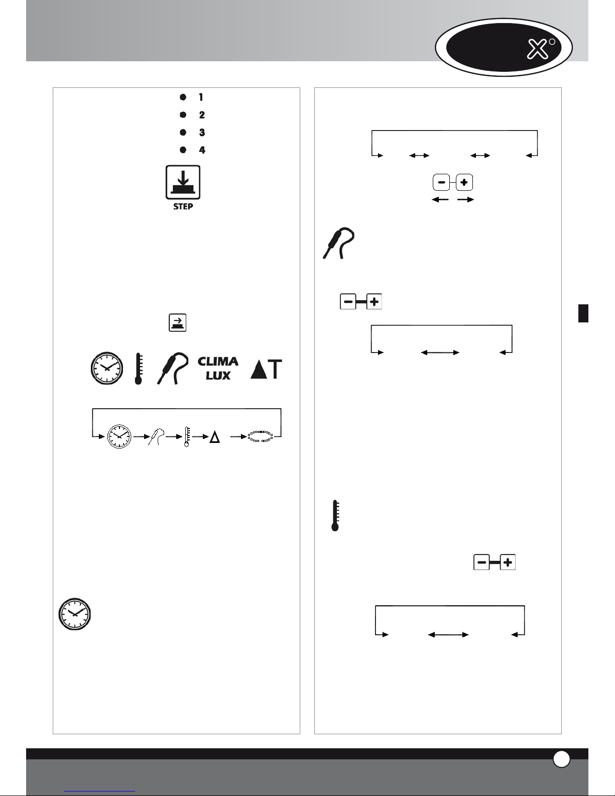
Für jeden einzelnen Schritt können Sie folgende Parameter einstellen:
Zeit, oder als alternative, Kerntemperatur
Garraumtemperatur, oder als alternative, Delta T
(nur möglich bei eingestellter Kerntemperatur)
Klima Einstellung (STEAM Maxi™ / DRY Maxi™)
Um von einem Parameter zum anderen zu wechseln
drücken Sie die Taste . Der ausgewählte Parameter wird durch eine der folgenden LED angezeigt
T
TIME
CORE
TEMPERATURE
CAVITY
TEMPERATURE
DELTA T
CLIMA
LUX
CLIMA LUX
Zeit
Kerntempe-
ratur
Garraumtem-
peratur
Delta T CLIMA
LUX
Folgende Parameter können nicht gleichzeitig gesetzt
werden:
ZEIT - KERNTEMPERATUR
GARRAUMTEMPERATUR - DELTA T
Ist keins der Parameter “ZEIT“ oder „KERNTEMPERATUR“ gesetzt können keine der anderen Parameter
eingestellt werden.
Einstellung ZEIT
Der Parameter ZEIT kann durch die Tasten eingestellt
werden und erscheint auf Display 1
Zeigt das Display “INF” an, bedeutet das, dass der Ofen
solange läuft bis der Benutzer den Ofen manuell stoppt.
Wenn die HOLD Funktion “HLD” bei den Schritten 2,
3 oder 5 gewählt ist, starten die Ventilatoren nur, wenn
•
•
•
die Heizelemente eingeschaltet sind. Bei jedem Start der
Ventilatoren, ändern sich die Richtungsumdrehungen.
STEP 1
0h 00' 9h 59'
inF
Einstellung KERNTERMPERATUR
Die KERNTEMPERATUR wird durch die Tasten
eingestellt und erscheint auf Display 1.
0°C 100°C
Sobald die KERNTEMPERATUR erreicht ist, endet
der Kochschritt und geht zum nächsten über, sofern
dieser eingestellt wurde.
Mit dem externen Kerntemperatur – Kit (XC240) kann
eine weitere Kerntemperaturnadel angeschlossen werden, diese ist extra dünn, um bei Vakuum verpackten
Lebensmitteln mit Kerntemperatur garen zu können.
Einstellung GARRAUMTEMPERATUR
Die GARRAUMTEMPERATUR wird auf Display 2 angezeigt und kann durch die Tasten
eingestellt
werden.
260°C0°C
14
ENGLISH
UNO
R
4
DEUTSCH
Page 50

Einstellung DELTA T
DELTA T wird auf Display 2 angezeigt und wir durch die
Tasten
eingestellt.
0°C 100°C
CLIMA LUX Einstellung Klima
Das Klima (STEAM.Maxi™/DRY Maxi™) im Ofen wird
durch die Tasten
eingestellt und kann an der
CLIMALUX Ellipse abgelesen werden.
STEAM
Maxi
DRY
Maxi
Die 10 blauen LED `s zeigen die prozentuale Dampfzugabe (STEAM.Maxi™) an; die 10 roten
LED `s zeigen die prozentuale Entfeuchtung im Garraum
an. (DRY.Maxi™).
KOCHEN Start / Stop
Um mit dem Gerät arbeiten zu können muss die Taste
betätigt werden Sobald der Ofen startet, leuchtet
die LED “START STOP”.
Um den Kochvorgang zu stoppen muss die Taste
ein weiteres mal zu drücken.
Wenn der Kochvorgang beendet ist, gibt der Ofen für 15
Sekunden ein hörbares Signal und das Display 1 blinkt für
45 Sekunden. Während diesen 45 Sekunden bleibt auch
die LED der Taste
„START / STOP“ an.
Drücken Sie nun die Taste um den Kochvorgang
verlängern zu können. Der Ofen fährt nun automatisch mit dem Programm fort.
Drücken Sie die Taste
so erlischt die “START /
STOP” LED und der Ofen schaltet sich wieder aus.
Wenn keine der Tasten gedrückt wird, schaltet die
„START / STOP“ LED nach 45 Sekunden automatisch ab.
Wenn ein Kochzyklus beendet ist, wird sowohl im Manuel
und im Programbetrieb, durch drücken der „P“ Taste
wird am Display „LASTP“ angezeigt: Beim Drücken der
„START / STOP“ Tast startet der zuletzt verwendetet
Kochzyklus.
3.6
Arbeiten mit den Programmen
LPUMP
L3
L2
L1
P01
P70
P02
P00
COOL
Auf der Bedienplatine können Sie bis zu 70 Programme
speichern und später bei gebrauch wieder abgerufen. Ein
Kühlprogramm und die Reinigungsprogramme (L1, L2,
L3, LH20) sind bereits vorprogrammiert.
Programmieren von Kochvorgän
-
gen:
Um einen Kochvorgang zu programmieren gehen sie wie
folgt vor:
Starten Sie den Programmier-Modus indem Sie die
Taste drücken
Das erste Display zeigt “Prg”, durch Drücken
Taste ist es Möglich die zu verändernde Einstellung
zu wählen; zum Ändern der Einstellung drücken Sie
Taste.
Drücken Sie
Taste und das erste Display zeigt
PRE an und alle vier LEDS der Vorgänge erlöschen.
Beim Drücken der
Taste, stellen Sie die Tem-
peratur als Absolutwert oder als Unterschiedswert
•
•
•
•
•
•
13
ENGLISH
5
DEUTSCH
ChefTop™ - BakerTop™
Page 51

ein. Das Garlämpchen oder das Delta T Lämpchen
erleuchten und sie können die erforderlichen Einstellungen abändern duch drücken von Taste.
Stellen Sie die gewünschten Parameter ein (Zeit,
Kerntemperatur, Garraumtemperatur, Delta T, Klima); jeder Kochvorgang kann in 4 Schritte unterteilt
werden.
Um das Programm zu speichern drücken Sie die Taste
für 5 Sekunden (nach erfolgreichen speichern ist
ein Ton zu hören)
Benutzen von vorgespeicherten
Programmen
(Kühlprogramm, Waschprogramm):
Um ein vorgespeichertes Programm abzurufen folgen Sie
den folgenden Schritten:
Starten Sie den Programm-Modus indem Sie die Taste
drücken
Wählen Sie das benötigte Programm mit den Tasten
aus.
Drücken Sie die Taste
um das Prgramm zu
starten
Sobald das ausgewählte Programm startet leuchtet
die “START / STOP” LED
Bei laufendem Programm können Sie die Parameter
nicht mehr umändern
Indem Sie die Taste
drücken können Sie das
Programm anhalten
Wenn Sie das Kochprogramm starten, fängt der Ofen an
sich vorzuheizen: Der Garraum heizt sich bis auf 30°C
über der eingestellten Temperatur auf. Während der Vorheiz- Phase, leuchten ausschließlich die „START / STOP“
LED ,das Display 1 zeigt „PRE“ und das Display 3 zeigt
das ausgewählte Programm an. Sobald die eingestellte
Temperatur erreicht ist, gibt der Ofen ein Signal und die
Displays zeigen die Parameter des ersten Schrittes an.
Nachdem der Ofen mit den Lebensmitteln bestückt wurde fängt das Programm automatisch an.
Wenn ein Kochzyklus beendet ist, wird sowohl im Manuel
und im Programbetrieb, durch drücken der „P“ Taste
wird am Display „LASTP“ angezeigt: Beim Drücken der
„START / STOP“ Tast startet der zuletzt verwendetet
Kochzyklus.
•
•
•
•
•
•
•
•
Reinigungsprogramm
Die ChefTop™ - BakerTop™ Geräte sind mit 3 Was-
chprogrammen ausgestattet (L1 kurz, L2 mittel, L3 lang) ,
ein Spülprogramm LH20 und das Programm zum befüllen
des Pumpensystems (LPUMP).
Hierfür wird das Rotor.KLEAN™ System benötigt.
Kühlprogramm “COOL”
“COOL” das Programm um den Garraum nach der Nutzung runter zu kühlen. Es funktioniert sogar mit geöffneten Türen.
Während des “COOL” Programms zeigt die Anzeige die
Garraumtemperatur.
WICHTIG
Es ist nicht möglich die Lüfterradblende ohne dem dafür
geeignetem Werkzeug zu entfernen. Wenn Sie die Lüfterradblende jedoch für einen Servicefall entfernen müssen,
trennen Sie die elektrische Zuleitung vom Ofen.
3.7
“ChefUnox” - “BakerUnox” Kochpro
gramme
PIZZA
BREAD
BAKE
POLLO
FRIES
STEAM
STEAM PRB1
ROAST
GRILL
SLOW
VACUO
REGEN
PIZZA ITALY
Die Bedienplatine “ChefTouch” - “BakerTouch” ist
mit automatischen Kochprogrammen ausgestattet: einfach nur den Prozess auswählen, und es ist möglich eine
große Menge verschiedenster Lebensmittel vom Ofen
automatisch zubereiten zu lassen. Für jeden Kochvorgang
haben Sie die Möglichkeit einige der Parameter an Ihre
eigenen Vorstellungen anzupassen.
Um die gespeicherten “ChefUnox” - “BakerUnox”
Programme aufzurufen verfahren Sie wie folgt:
Drücken Sie die Taste
Wählen Sie das benötigte Programm durch die Tasten
aus
Nun ist es möglich die Parameter durch drücken der
Taste zu ändern, als zweiten Schritt verstellen
•
•
•
14
ENGLISH
UNO
R
6
DEUTSCH
Page 52

Sie die Parameter mit den Tasten . (Falls
Sie das geänderte Programm beibehalten möchten
speichern Sie das Programm mit der Taste )
Starten Sie das Programm indem Sie die Taste
drücken
Wenn das Programm startet fängt die LED “START/
STOP” an zu leuchten
Während des Kochprogramms ist es nicht möglich die
Parameter umzuändern
Sie können den Kochvorgang durch drücken der
Taste stoppen
AUTOMATISCHE KOCHPROZESSE FÜR BESTIMMTE PRODUKTFAMILIEN
“PIZZA ITALY”
Programm zum backen von dünner Pizza.
Änderbarer Parameter: Backzeit
Es wird empfohlen die Pizzaplatte “FAKIRO” TG860
zu verwenden.
“PIZZA”
Programm zum backen von dicker Pizza
Änderbarer Parameter: Backzeit
“BREAD”
Programm zum backen von Brot und ähnlichen Produkten (type of bread).
Der Kerntemperaturfühler wird benötigt, um zu kontrollieren ob das Brot fertig ist.
Änderbarer Parameter: Kerntemperatur
“BAKE”
Programm zum backen von Kuchen und Pasteten (type
of pastry).
Der Kerntemperaturfühler zeigt ob die Backware fertig
gebacken ist.
Änderbarer Parameter: Kerntemperatur
•
•
•
•
“POLLO” (nur für die ChefTop™)
Programm zum garen von Grillhähnchen
Änderbarer Parameter: Kerntemperatur
Es wird empfohlen, hierbei das Hähnchengrillrost Pollo
GRP810 zu verwenden. Da es exakt auf das perfekte
Hähnchen abgestimmt ist. Das Program besteht aus einer
Vorheizphase bis zu einer Temperatur von 250°C und 4
Kochschritten mit Temperaturen von 180° bis 205°C.
“FRIES” (nur für die ChefTop™)
Programm zum backen von Pommes Frites.
Änderbarer Parameter: Kerntemperatur
Es wird empfohlen das Rost „No Fry“ GRP815 zu
verwenden. Es wurde von UNOX entwickelt um Fritten
ohne Fett aber dennoch mit viel Geschmack backen zu
können.
AUTOMATISCHE KOCHVORGÄNGE
“REGEN“ Regenerieren von Speisen
Regenerieren von vorbereiteten Lebensmitteln
Änderbarer Parameter: Regenerationszeit.
“VACUO“
(nur möglich wenn der externe Kernemperaturfühler installiert ist)
Programm zum kochen von vakuumierten Lebensmitteln
Änderbarer Parameter: Kerntemperatur.
Die sehr dünne Kerntepmeraturnadel verhindert das
reißen der Vakuumverpackung.
“STEAM” (nur für die ChefTop™)
Gut geeignet zum garen von Fleisch, Fisch, Gemüse und
Kartoffeln.
Ändererbarer Parameter: Kerntemperatur.
Bei diesem Kochvorgang drehen sich die Lüfterräder
ausschließlich im Uhrzeigersinn. (es gibt keinen reversierendes Zahnrad)
Die Menge der Wasserbedarfs im innern des Garraums
ist abhängig von der Temperatureinstellung: je höher die
Temperatur, desto niedriger ist der Wasserbedarf. Der
Ofen errechnet automatisch die genaue Menge Wasser
auf Basis der Temperatureinstellung.
13
ENGLISH
7
DEUTSCH
ChefTop™ - BakerTop™
Page 53

“STEAM PRB1“ (nur für die ChefTop™)
(nur möglich wenn der externe Kernemperaturfühler installiert ist)
Gut geeignet für Lebensmittel wie Würste, Fisch und
gedämpftes Gemüse. Der externe Kerntemperaturfühler
stellt fest ob die Lebensmittel fertig gegart sind.
Änderbarer Parameter: Kerntemperatur
Bei diesem Kochvorgang drehen sich die Lüfterräder
ausschließlich im Uhrzeigersinn.
“SLOW “(nur für die ChefTop™)
Gut geeignet für Niedertamperaturgaren und somit perfekt für groß portioniertes Fleisch
Änderbarer Parameter: Kerntemperatur um zwischen Englisch, Medium und Durch zu variieren;
“ROAST” (nur für die ChefTop™)
Gut geeignet um Fisch oder Fleisch zu garen.
Änderbarer Parameter: Kerntemperatur um zwischen Englisch, Medium und Durch zu variieren;
Hier wird empfohlen das Blech Black TG835 zu nutzen.
“GRILL” (nur für die ChefTop™)
Perfekt geeignet zum grillen von Fisch und Fleisch.
Änderbarer Parameter: Kerntemperatur um zwischen Englisch, Medium und Durch zu variieren;
Es wird empfohlen, zum grillen das Blech “FAKIRO
Grill“ zu benutzen. Es wurde speziell für diesen Vorgang entwickelt.
3.8 NUTZUNG MEHRERER GERÄTE ÜBER EINE
BEDIENPLATINE
Die digitale Bedienplatine “ChefTouch” - “BakerTouch” ermöglicht es Ihnen, mehrere ChefTop - Bak-
erTop Geräte über die Bedienplatine eines Ofens zu
bedienen. Darüber hinaus können Sie durch das MASTER
& SLAVE System über eine Bedienplatine mehrere Öfen
steuern. Der Ofen über den alle andern Geräte gesteuert
werden wird zum “MASTER“ Ofen. Die anderen Geräte
werden zum “SLAVE“ Ofen und deren Bedienplatine
wird inaktiv.
Die Auswahl des zu kontrollierenden Geräts wird durch
die Taste gemacht. Die Nummer des Gerätes wird auf
Display 4 angezeigt.
Liste Gerätenummern
Geräte-
nummer
Geräte- typ Gerät
1 ChefTop™ Master Ofen
2 ChefTop™ slave 2
3 ChefTop™ slave 3
4 XK304 Schockfroster
5 XL314 Warmhalteschrank
7 XC314 Abzugshaub
8 XC224 Umkehrosmose System
Geräte-
nummer
Geräte-
typ
Gerät
1 BakerTop™ Master Ofen
2 BakerTop™ slave 2
3 BakerTop™ slave 3
5 XL 404
Gärshrank
7 XC 414 Abzugshaub
8 XC224 Umkehrosmose System
Durch die einfache Bedienungsverteilung auf eine Bedienplatine, wird ein leichteres und schnelleres Arbeiten
garantiert.
4. GRUNDSÄTZE BEIM KOCHEN
4.1 Variable Parameter
Zeit
Diese variable hängt größtenteils von der Menge der zu
garenden Lebensmittel ab.
Je größer die Menge der Lebensmittel desto mehr Zeit
wird zum Garen benötigt.
Garraumtemperatur
Die exakte Garraumtemperatur garantiert das perfekte
Ergebnis ob von innen oder von außen.
eine zu niedrigere Temperatur lässt das Fleisch trocken werden.
bei einer zu hohe Temperatur verbrennt das Fleisch
von außen und von innen bleibt er roh.
Entfeuchtung
Das “DRY.Maxi™” System, von UNOX patentiert, ermöglicht es Ihnen die Feuchtigkeit aus dem Garraum
zu ziehen. Auf diese Weise wird das Produkt von außen
knusprig (z.B. bei Brot), während es von innen eine
gleichmäßige Struktur bekommt.
Beschwadung
Die Beschwadung durch die Zugabe von Dampf (STEAM.
•
•
14
ENGLISH
UNO
R
8
DEUTSCH
Page 54

Maxi™) kann in zwei verschiedenen Arten angewandt
werden:
Beschwaden (nur Dampf);
Beschwaden und Heißluft (Luft+Dampf).
4.2 Empfehlungen für gleichmäßiges Garen
Vorheizen
Beim Vorheizen ist es immer besser den Ofen um 30
– 50°C höher als die benötigte Temperatur aufzuheizen,
da beim öffnen der Tür etwas Hitze verloren geht.
Die Bleche
Um die perfekte Bräunung des Produktes zu gewährleisten, dürfen die Bleche nicht zu tief sein. Da ansonsten
keine optimale Luftzirkulation gegeben ist.
Platz zwischen den Blechen
Für gleichmäßiges Garen ist es wichtig zwischen dem
zu garenden Produkt und dem darüber liegenden Blech
einen mindest Abstand von 3 cm einzuhalten.
Menge der Lebensmittel
Man muss darauf achten, dass, gerade bei Brot und
Kuchen, die Bleche nicht zu voll belegt werden, da ansonsten der Luftstrom nicht optimal fließen kann.
Positionieren des Kerntemperaturfühlers
Damit der Kerntemperaturfühler korrekt funktionieren
kann, ist es wichtig, ihn von oben in die dickste Stelle bis
ins Zentrum des Gargutes zu stecken.
In dem Fall, dass das Gargut sehr dünn ist, kann der Kerntemperaturfühler auch horizontal von der Seite eingeführt werden.
WICHTIG!
Kombidämpfer benötien ca. 20 – 40 °C weniger als statische Öfen. Vorsicht beim öffnen der Tür, da die Hitze und
der Dampf schwere Verbrennungen verursachen können.
4.3 Einfaches Garen
Temperatur: 30°C bis 260°C
Kombidämpfen funktioniert mit im Garraum zirkulierender Heißluft. Dieses ermöglicht ein gleichmäßiges
garen. Auch bei einem stark belegten Dämpfer ist es
möglich außen kross und innen saftig zu garen.
Geeignet für: Überbacken, grillen und braten
Vorteile: es besteht die Möglichkeit verschiedene Lebensmittel wie Gemüse, Fleisch und Fisch gleichzeitig zu garen ohne
die Aromen zu vermischen (vorausgesetzt die verschiedenen
Produkte haben die gleichen Parametereinstellungen).
•
•
4.4 Garen mit Heißluft und Beschwadung
Temperatur: 30°C bis 260°C
Beschwadung: 30% bis 90%
Hier wird mit Heißluft in Verbindung von Dampf gegart.
Es ist sicherlich eine der profitabelsten Garmöglichkeiten
unter den heutigen Methoden.
Die Garzeiten werden hierdurch reduziert und die Lebensmittel werden unvergleichbar zart ohne an viel Gewicht zu verlieren.
Gut geeignet für: Braten, Roast beef, geschmortes Fleisch,
Fisch
Tipp:
Um einen Braten machen zu können ist es besser ein beschichtetes Blech zu nehmen.
4.5 Dämpfen
Temperatur 48°C bis 130°C
Beschwadung: 100%
Durch das Dämpfen verliert das Gargut so gut wie keine
Flüssigkeit, sodass es saftig und lecker auf dem Teller landet.
Gut geeignet für:
Niedertemperaturgaren: Gemüse, Obst, Suppen,
Soufflés, Vakuumkochen
Dämpfen: Gemüse, Obst, Eier, Fleisch, Fisch
Starkes Dämpfen: Kartoffeln
Tipp:
Um Blattgemüse mit Dampf zubereiten zu können, wird
empfohlen es leicht zu befeuchten, um das Austrocknen der
Blätter zu verhindern. Um das Blattgemüse vor der Luftzirkulation zu schützen, nutzen Sie am besten zwei unserer
„NoFry“ Bleche, einen als Blech und einen als Deckel.
4.6 Backen
Temperatur: von 30°C bis 260°C
Kombidämpfen wird mit heißer trockener und zirkulierender Luft erreicht. Hierdurch kann eine perfekte
Hitzeverteilung im Garraum garantiert werden sodass ein
gleichmäßiges Backergebnis gegeben ist, sogar wenn der
Ofen komplett bestückt wurde.
Ebenfalls Kuchen wird mit einem einwandfreien Backergebnis gebacken Außen knusprig braun, und innen mit
einer schönen lockeren Struktur.
Geeignet zum Backen von:
•
•
•
13
ENGLISH
9
DEUTSCH
ChefTop™ - BakerTop™
Page 55

• Kleinem Gebäck, Blätterteig, Obstkuchen
• Biskuitkuchen
• Keksen
Tipp:
Um gute Resultate Beim backen von Kuchen erzielen zu
können, ist es notwendig einen größeren Abstand zwischen
den Blechen wie auch zwischen den Backwaren selber einzuhalten.
Bei Produkten mit einer leichten Masse ist es wichtig die
Luftstromreduzierscheibe zu nutzen, damit die Backware
nicht durch den Luftstrom vom Blech gepustet werden.
4.7 Garen und Befeuchten von Produkten
Temperatur 30°C bis 260°C
Befeuchtung 10% bis 20%
Gebacken wird mit heißer Luft und einem variablen Prozentsatz von Befeuchtung, je nach dem welches Produkt
gebacken werden soll.
Geeignet zum backen von:
• Sauerteig wie zum Beispiel Brot
• Croissants
Tipp:
Das Anwenden von Befeuchtung zu Beginn des Backvorgangs
lässt den Teig besser aufgehen; anschließend kann die Befeuchtung reduziert werden oder sogar auf 0 % gesetzt werden, damit eine goldene Kruste gewährleistet ist.
4.8 Garen von Produkten mit dem DRY.Maxi™ System
“DRY.Maxi™” System (UNOX weltweit patentiert)
Temperatur 30 % bis 260°C
Entfeuchtung 10% bis 100%
Dieses innovative System ermöglicht es Ihnen, dem Gargut sowie dem Garraum komplett die Feuchtigkeit zu
entziehen.
Geeignet zum Backen von:
• Croissants
• Keksen
• Brot
4.9 Garen mit Kerntemperaturfühler und Garraumtemperatur
Mit diesem Kochprozess, muss die Kerntemperatur und
die Garraumtemperatur eingestellt werden. Der Kerntemperaturfühler misst die ansteigende Temperatur im
Innern des Gargutes, sie muss im dicksten Stück des Gar-
gutes platziert werden.
Nun ist es nicht mehr nötig den Parameter Zeit einzustellen. Bei erreichter Kerntemperatur schaltet sich der
Ofen aus oder, sofern eingestellt, geht er zum nächsten
Programmschritt über.
Kochen mit Kerntemperatur optimiert das Kochen mit
verschiedenen Lebensmittelsorten und ermöglicht eine
bessere Kontrolle über die Lebensmittel während der
einzelnen Schritte.
Core probe + 100°C ∆T
Sonda al cuore +
∆T a 100°C
Kerntemperaturfühler und Gar-
raumtemperatur
Garraumtemperatur
KERNTEMPERATUR
G
A
R
R
A
U
M
Zeit in Minuten
Temperatur
4.10 Garen mit Kerntemperaturfühler und Delta T
Bei dieser Garart stellen Sie einfach die gewünschte Kerntemperatur und die Delta T Temperatur ein. (Differenz
zwischen Kerntemperatur und Garraumtemperatur)
GARRAUMTEMPERATUR =
KERNTEMPERATUR + DELTA T
Bei dieser Garart steigt die Garraumtemperatur allmählich, sodass die Delta T Temperatur konstant gehalten
werden kann.
Bei diesem Garprozess können wir Ihnen garantieren,
dass die zu garenden Lebensmittel (gerade Fleisch) so
schonend wie möglich gegart werden.
Kerntemperaturfühler + 100°C ∆T
G
A
R
R
A
U
M
Zeit in Minuten
Temperatur
KERNTEMPERATUR
A
N
S
T
E
I
G
E
N
D
E
T
E
M
P
E
R
A
T
U
R
14
ENGLISH
UNO
R
10
DEUTSCH
Page 56

Kerntemperaturfühler + 50°C ∆T
A
N
S
T
E
I
G
E
N
D
E
T
E
M
P
E
R
A
T
U
R
G
A
R
R
A
U
M
KERNTEMPERATUR
Zeit in Minuten
Temperatur
5. Verschiedene Anschlüsse
Die digitale Bedienplatine der ChefTop™ - BakerTop™ Öfen hat unterschiedliche Anschlüsse wie USB,
Bluetooth®, serielle Verbindungen etc.
Das Set XC226 gibt es bereits mit folgenden Funktionen:
Überspielen von Kochprogrammen
Änderung an Programmen
Problemdiagnose
Verbindung zum Drucker
Im Set (XC226) finden Sie noch weitere Informationen.
6. Instandhaltung
Instandhaltungsmaßnahmen dürfen ausschließlich von
dafür qualifiziertem Personal durchgeführt werden. Bevor Instandhaltungsmaßnahmen durchgeführt werden,
trennen Sie den Ofen bitte von der Stromverbindung.
Das Gerät muss regelmäßig gewartet werden (mindestens
einmal im Jahr). Die Wartung dard wiederum nur von
einem qualifizierten Techniker vorgenommen werden.
6.1 Austauschen der Garraumbeleuchtung
Um die Garraumbeleuchtung zu wechseln gehen Sie wie
folgt vor:
trennen Sie das Gerät von der Stromverbindung und
lassen Sie es abkühlen
entfernen Sie die Einhangschienen
schrauben Sie das Schutzglas ab und tauschen Sie das
Leuchtmittel aus
schrauben Sie das Schutzglas wieder fest
befestigen Sie die Einhangschienen wieder an seinem
Platz
•
•
•
•
•
•
•
•
•
7. WARTUNG
Wartungen sollten ausschließlich von einem Techniker
durchgeführt werden. Trennen Sie für Wartungen das
Gerät von der Stromverbindung und lassen Sie es abkühlen. Schrauben Sie die Rückwand ab um Zugriff auf alle
Anschlüsse zu haben.
7.1 Reset Taste beim Sicherheitsthermostat
Das Gerät ist mit einem Sicherheitsthermostat mit Reset Taste ausgestattet. Dieses Sicherheitsthermostat wird
benötigt, um den Ofen vor Überhitzung zu schützen.
Sobald das Sicherheitsthermostat reagiert, bricht es sofort die Verbindung zum Heizelement ab und das Display
zeigt die Fehlermeldung EF4.
Um das Sicherheitsthermostat wieder in betrieb zu nehmen, schrauben Sie die Schutzkappe auf der Rückseite
des Ofens ab und drücken Sie den darunter liegenden
Knopf. Das Thermostat fängt nun wieder an zu arbeiten.
8. Ausschalten bei Funktionsstörungen
Bei Funktionsstörungen des Ofens ist folgenden zu tun:
Trennen Sie das Gerät von der Stromversorgung
Kontaktieren Sie den UNOX Kundendiens
•
•
13
ENGLISH
11
DEUTSCH
ChefTop™ - BakerTop™
Page 57

9. Funktionsstörungen, Problemursachen und Problembehebung
Die unten aufgeführte Liste hilft Ihnen kleine Probleme selbst zu beheben.
PROBLEM URSACHE LÖSUNG
Die
Hauptversorgungsspannung
fehlt
Stellen Sie die
Hauptversorgungsspannung
wieder her
Der Stromanschluss wurde
falsch montiert
wenden Sie sich an einen
Techniker
Der Ofen schaltet sich komplett ab
Eine der Sicherungen ist
defekt
Prüfen Sie die Sicherungen
Der Wasserzulauf ist
abgedreht
Öffnen Sie den Wasserzulauf
Die Verbindung zum
Wasserzulauf wurde falsch
montiert
Prüfen Sie die Verbindung zum
Wasserzulauf
Der Wassertank ist leer
(sofern Sie das Wasser aus
einem Tank beziehen)
Füllen Sie den Tank mit Wasser
Der Wasserzulauf funktioniert nicht
Der Filter des Wasserzulaufs
ist verstopft
Reinigen Sie den Wasserfilter
Die Tür ist nicht richtig
verschlossen
Schließen Sie die Tür
Der Ofen startet nicht obwohl Sie
eine Garzeit eingestellt haben und
die Start&/Stopp Taste betätigt
haben.
Der Türkontaktschalter ist
defekt
Wenden Sie sich an einen UNOX
Techniker
Defekte Türdichtung
Wenden Sie sich an einen UNOX
Techniker
Wasser kommt durch die Tür und
durch die Dichtung obwohl die Tür
geschlossen ist
Defekt am Türmechanismus
Wenden Sie sich an einen UNOX
Techniker
Defektes Leuchtmittel Ersetzen Sie die Lampe
Das Licht im Ofen funktioniert nicht
mehr
Das Leuchtmittel fehlt
Platzieren Sie die Lampe in der
Fassung
Die Lüfterräder reversieren
nicht mehr
Wenden Sie sich an einen UNOX
Techniker
Eines der Lüfterräder
funktioniert nicht
Wenden Sie sich an einen UNOX
Techniker
Das Garergebnis ist nicht
gleichmäßig
Eins der Heizelemente
funktioniert nicht
Wenden Sie sich an einen UNOX
Techniker
14
ENGLISH
UNO
R
12
DEUTSCH
Page 58
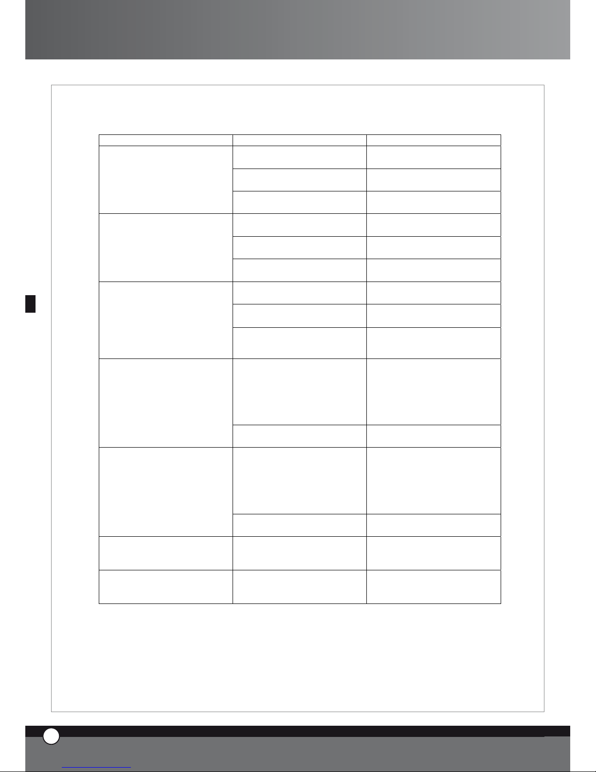
10. Fehlermeldungen
10.1 Fehlermeldungen der Öfen
PROBLEM URSACHE LÖSUNG
Der Garraumfühler hat sich von
der Platine gelöst
Wenden Sie sich an einen UNOX
Techniker
Der Garraumfühler ist defekt
Wenden Sie sich an einen UNOX
Techniker
Die Bedienplatine zeigt die
Fehlermeldung EF1 an
Die Powerplatine ist defekt
Wenden Sie sich an einen UNOX
Techniker
Der 2. Garraumfühler hat sich
von der Platine gelöst
Wenden Sie sich an einen UNOX
Techniker
Der 2. Garraumfühler ist defekt
Wenden Sie sich an einen UNOX
Techniker
Die Bedienplatine zeigt die
Fehlermeldung EF2 an
Die Powerplatine ist defekt
Wenden Sie sich an einen UNOX
Techniker
Die Kerntemperaturfühler hat
sich von der Platine gelöst
Wenden Sie sich an einen UNOX
Techniker
Der Kerntemperaturfühler ist
defekt
Wenden Sie sich an einen UNOX
Techniker
Die Bedienplatine zeigt die
Fehlermeldung EF3 an
Die Powerplatine ist defekt
Wenden Sie sich an einen UNOX
Techniker
Thermoschutz des Motors hat
ausgelöst
Trennen Sie die Verbindung zur
Stromversorgung, lassen Sie den
Ofen abkühlen und starten Sie
ihn erneut.
Wenden Sie sich an einen UNOX
Techniker
Die Bedienplatine zeigt die
Fehlermeldung EF4 an
Die Powerplatine ist defekt
Wenden Sie sich an einen UNOX
Techniker
Sicherheitsthermostat hat
ausgelöst
Trennen Sie die Verbindung zur
Stromversorgung, lassen Sie den
Ofen abkühlen und starten Sie
ihn erneut.
Wenden Sie sich an einen UNOX
Techniker
Die Bedienplatine zeigt die
Fehlermeldung EF5 an
Die Powerplatine ist defekt
Wenden Sie sich an einen UNOX
Techniker
Display Nr.1 zeigt permanent
EF6 an
Powerplatine/ Verbindungskabel
ist beschädigt oder nicht
verbunden
Bitte für Service an einen
qualifizierten UNOX Techniker
wenden
Display Nr.1 zeigt permanent
EF7 an
Verlust der Kommunikation
zwischen dem Ofen und den
verbundenen Zusatzgeräte
Bitte für Service an einen
qualifizierten UNOX Techniker
wenden
13
ENGLISH
13
DEUTSCH
ChefTop™ - BakerTop™
Page 59

10.2 Fehlermeldungen der Schockfroster
PROBLEM URSACHE LÖSUNG
Der Temperaturfühler hat sich
von der Platine gelöst
Wenden Sie sich an einen
UNOX Techniker
Der Temperaturfühler ist defekt Wenden Sie sich an einen
UNOX Techniker
Die Bedienplatine zeigt die
Fehlermeldung EA1 an
Die Powerplatine des
Schockfrosters ist defekt
Wenden Sie sich an einen
UNOX Techniker
Der Kerntemperaturfühler hat
sich von der Platine gelöst
Wenden Sie sich an einen
UNOX Techniker
Der Kerntemperaturfühler ist
defekt
Wenden Sie sich an einen
UNOX Techniker
Die Bedienplatine zeigt die
Fehlermeldung EA2 an
Die Powerplatine des
Schockfrosters ist defekt
Wenden Sie sich an einen
UNOX Techniker
Im Gefrierkreislauf herrscht
Überdruck
Trennen Sie die Verbindung zur
Stromversorgung, warten Sie 20
Minuten und starten Sie das
Gerät neu. Zeigt das Gerät
immer noch EA3
wenden Sie sich bitte an einen
UNOX Techniker
Die Bedienplatine zeigt die
Fehlermeldung EA3 an
Die Powerplatine des
Schockfrosters ist defekt
Wenden Sie sich an einen
UNOX Techniker
Display Nr. 1 zeigt permanent
EA4
Arbeitsgrenze des Filters erreicht
Nehmen Sie den Filter heraus
und reinigen Sie ihn
Verbindunskabel zwischen Ofen
uns Schockfroster ist nicht
verbunden/beschädigt
Display Nr. 1 zeigt permanent
EA5 an.
Powerplatine des Schockfrosters
beschädigt
Bitte für Service an einen
qualifizierten UNOX Techniker
wenden
10.3 Fehlermeldungen des Warmhalteschranks
PROBLEM URSACHE LÖSUNG
Der Temperaturfühler hat sich von
der Platine gelöst
Wenden Sie sich an einen UNOX
Techniker
Der Temperaturfühler ist defekt
Wenden Sie sich an einen UNOX
Techniker
Die Bedienplatine zeigt die
Fehlermeldung EL1 an
Die Powerplatine des
Warmhalteschrankes ist defekt
Wenden Sie sich an einen UNOX
Techniker
Der Feuchtigkeitsfühler hat sich von
der Platine gelöst
Wenden Sie sich an einen UNOX
Techniker
Der Feuchtigkeitsfühler ist defekt
Wenden Sie sich an einen UNOX
Techniker
Die Bedienplatine zeigt die
Fehlermeldung EL2 an
Die Powerplatine des
Warmhalteschrankes ist defekt
Wenden Sie sich an einen UNOX
Techniker
Verbindungskabel zwischen Ofen
und Wärmeschrank defekt/ nicht
verbunden
Display Nr. 1 zeigt permanent
EL3 an
Wärmeschrankpowerplatine defekt
Bitte für Service an einen
qualifizierten UNOX Techniker
wenden
14
ENGLISH
UNO
R
14
DEUTSCH
Page 60

10.4 Fehlermeldungen der Abzugshaube
PROBLEM URSACHE LÖSUNG
Die Anschlußleitungen der
Garraumfühlers sind von der
Powerplatine getrennt
Bitte wenden Sie sich an einen
qualifizierten UNOX Techniker
beschädigte Garraumfühler
Bitte wenden Sie sich an einen
qualifizierten UNOX Techniker
Das Display 1 zeigt
ununterbrochen EC1 an
Beschädigte Powerplatine von der
Abzugshaube
Bitte wenden Sie sich an einen
qualifizierten UNOX Techniker
Verbindungskabel zwischen Ofen
und Abzugshaube ist beschädigt
oder getrennt
Display 1 zeigt ununterbrochen
EC2 an
Powerplatine zu Abzugshaube ist
beschädigt
Bitte wenden Sie sich an einen
qualifizierten UNOX Techniker
10.5 Fehlermeldungen des Umkehrosmose Systems
PROBLEM
URSACHE
LÖSUNG
Druckgeber ist beschädigt
Verbindungskabel zwischen
Signalgeber und Powerplatine
beschädigt/ nicht verbunden
Display Nr. 1 zeigt permanent
EO1 an
Powerplatine zur Umkehrosmose
beschädigt
Bitte für Service an einen
qualifizierten UNOX Techniker
wenden
Literzähler ist beschädigt
Verbindungskabel zwischen
Literzähler und Powerplatine
beschädgit oder nicht verbunden
Display Nr. 1 zeigt permanent
EO2 an
Powerplatine zu Umkehrosmose
beschädigt
Bitte für Service an einen
qualifizierten UNOX Techniker
wenden
Display Nr. 1 zeigt permanent
EO4 an
Arbeitsgrenze des Filters erreicht
Bitte für Service an einen
qualifizierten UNOX Techniker
wenden
Display Nr. 1 zeigt permanent
EO4 an
eingehender Wasserdruch ist zu
niedrig
Verbindungskabel zwischen Ofen
und Umkehrosmose beschädigt
Display Nr. 1 zeigt permanent
EO5 an
Powerplatein zu Umkehrosmose
beschädigt!!
Bitte für Service an einen
qualifizierten UNOX Techniker
wenden
13
ENGLISH
15
DEUTSCH
ChefTop™ - BakerTop™
Page 61

B. ANLEITUNG FÜR DEN IN-
STALLATEUR
1. EINFÜHRUNG
Alle Installationsarbeiten dürfen nur von dafür qualifiziertem Fachpersonal durchgeführt werden.
Lesen Sie diese Betriebsanleitung sehr sorgfältig bevor
Sie mit den Installationsarbeiten beginnen.
Prüfen Sie das Gerät auf eventuelle Transportschäden
und entfernen Sie alle Informationsblätter aus dem Garraum.
2. INSTALLATIONSVORBEREITUNGEN
2.1 PRÜFUNG VOR DER INSTALLATION
Vor dem Installieren des Gerätes, prüfen Sie bitte alle
Anschlüsse wie die Elektro- und Wasseranschlüssen
aber auch das Abzugsrohr, wie auf den Bildern der beigefügten Datei „Technische Daten“ zu sehen.
2.2 VORBEREITUNG ZUR POSITIONIERUNG
Die Füße zum Gerät finden Sie im Garraum des Ofens.
Nutzen Sie das Geräte niemals ohne zuvor die Füße
anzuschrauben.
Schrauben Sie die Tropfschale von der Rückseite ab und
montieren Sie in an der dafür vorgesehenen Stelle.
Platzieren Sie nun den Ofen an seinem Platz.
Stecken Sie die Füße an die dafür vorgesehenen Löcher
an der Unterseite des Ofens.
14
ENGLISH
UNO
R
16
DEUTSCH
2.3 ENTFERNEN DER SCHUTZFOLIE
Entfernen Sie vorsichtig die Schutzfolie vom Außengehäuse des Gerätes. Achten Sie darauf, dass keine Klebstoffrückstände auf dem Edelstahl zurückbleiben.
Sollten trotzdem Rückstände vom Klebstoff bleiben, entfernen Sie diese mit einem geeigneten Lösungsmittel.
Entfernen Sie den Schutz vom Kerntemperaturfühler.
2.4 POSITIONIERUNG
Platzieren Sie das Gerät unter Berücksichtigung der folgenden Sicherheitsstandards.
Platzieren Sie das Gerät so, dass Sie die Rückseite leicht
erreichen können, um elektrische Arbeiten zu erledigen.
Der Ofen ist nicht für einen festen Einbau geeignet.
Es ist wichtig auf jeder Seite des Gerätes 5 cm Platz zu
lassen.
Page 62

Sämtliche Modelle der ChefTop™ - BakerTop™ Serie
sollten auf einer dafür geeigneten Standfläche, wie einem
Tisch, einem Gärschrank oder einem Unterbau positioniert werden.
Installieren Sie das Gerät niemals auf dem Fußboden.
Falls das Gerät in der Nähe von Wänden steht müssen
Sie sicherstellen, dass diese nicht aus brennbaren Material
bestehen.
Andererseits müssen diese Wände mit einer feuerfesten
Dämmung verkleidet werden, wie im Feuerschutzgesetz
vorgegeben.
Installieren Sie den Ofen nicht in der Nähe eines Gefrierschrankes.
Stellen Sie sicher, dass der Ofen auf einer ebenen Fläche
positioniert wird.
3. ELEKTROANSCHLUSS
3.1 Der Anschluss an das Elektrische Stromnetz muss
nach den folgenden Standards erfolgen:
Vor dem Anschluss vergewissern Sie sich, dass die
Spannung und Frequenz des Stromnetzes zu der
des Gerätes, wie auf dem Typenschild beschrieben,
passt.
Der Anschluss muss für die entsprechende Leistungsabnahme ausgelegt sein.
Das Gerät muss mit einem allpoligen Netztrennschalter (Magnet- Thermoschalter) mit einer
Kontaktöffnung von mindestens 3 mm vom Netz getrennt werden.
Wenn das Gerät arbeitet, darf die Versorgungsteilspannung nicht mehr als ± 10 % vom Wert der
Nennspannung abweichen.
Der Schutzleiter muss vorschriftsmäßig angeschlossen sein.
Das Gerät verfügt
•
•
•
•
•
•
3.2 ANSCHLUSS DES KABELS
Um das Kabel zu tauschen gehen Sie bitte wie folgt vor:
öffnen Sie Verschlusskappe zum Elektroanschluss
verbinden Sie die Leitungen wie in der beigelegten
Zeichnung
fixieren Sie die Kabel
schließen Sie die Verschlusskappe
ACHTUNG
Schrauben Sie das Kabel zusammen mit der Kupferbrücke, wie auf der Zeichnung gezeigt, am Steuerboard
fest. Ziehen Sie die Schraube gut fest, sodass diese sich
später nicht mehr lösen kann.
Gehen Sie sicher dass die Verbindungen korrekt sind, da
ein falscher Anschluss zur Überhitzung führt.
3.3 POTENTIAL AUSGLEICH
Das Gerät verfügt über eine Erdungsklemme, welche
über einen 10 mm Leiter an einen Potentialausgleich angeschlossen werden muss.
4. WASSERANSCHLUSS
4.1 Vor den Geräten sollte ein Wasserfiltersystem mit
Wasserhahn installiert werden.
Wie nach gegenwärtigen Gesetzen erforderlich werden
die Geräte mit einem 2 Meter Schlauch und mechanischem Filter geliefert.
Bevor Sie das Gerät mit der Wasserleitung verbinden,
sollten Sie etwas Wasser durch den Schlauch fließen las-
•
•
•
•
13
ENGLISH
17
DEUTSCH
ChefTop™ - BakerTop™
Page 63

14
ENGLISH
UNO
R
18
DEUTSCH
sen um ihn von eventuellen Rückständen zu befreien.
Das Wasser das für den Ofen gebraucht wird, sollte einen
Druck zwischen 1 und 3 Bar und eine Höchsttemperatur
von 30 °C haben.
4.2 BEREITUNG DES WASSERS
Das Wasser darf eine Härte von höchstens 5° haben (das
minimiert die Bildung von Kalk im Garraum).
Es wird empfohlen ein Wasseraufbereitungssystem (Umkehrosmose) vorzuschalten um mögliche Ablagerungen
von Kalk oder anderen Mineralien zu vermeiden. Die
ideale Lösung für dieses Problem kommt aus dem Hause
UNOX. Ein Umkehrosmosesystem zur Wasseraufbereitung filtert mit einer speziellen Membran das Wasser.
5. WASSERABFLUSS
5.1 ACHTUNG
Das Wasser das aus dem Abfluss kommt kann bis zu 90°C
heiß sein. Aus diesem Grund müssen Schläuche die an
dieser Stelle installiert werden für hohe Temperaturen
geeignet sein.
5.2 ABFLUSS
Der Wasserabfluss befindet sich auf der Rückseite des
Ofens. Er muss mit einem hitzebeständigen Schlauch
oder einem Rohr mit dem Abfluss verbunden sein; dabei
darf der Durchmesser des Abflussschlauches nicht kleiner
als der des am Ofen befestigten Rohrs sein und darf einen
Meter Länge nicht überschreiten.
Versuchen Sie Biegungen und enge Durchflüsse zu vermeiden.
Der Schlauch muss mindestens 20 cm unter dem Abflussrohr enden, um zu gewährleisten, dass das Wasser
gut abfließen kann.
5.3 DAMPFABZUG
Der Dampfabzug befindet sich auf der Rückseite des
Ofens. Der Abzug darf auf keinen Fall verstopft werden,
damit der Dampf ordnungsgemäß austreten kann.
Gehen Sie sicher, dass sich keine Gegenstände über dem
Dampfabzug befinden, die hierdurch beschädigt werden
könnten.
Wir weisen darauf hin, dass es in jedem Fall am besten
ist eine Abzugshaube zu nutzen. Das passende Modell
aus dem Hause UNOX XC314 für ChefTop™ - XC 414
für BakerTop™ oder einen Dampfkondensator XC114
sind perfekt auf unsere Geräte abgestimmt.
In jedem Fall aber, sollte der Dampf durch einen hitzebeständigen Schlauch geleitet werden (TB1520A0)
6. ANSCHLUSS DES
ZUSATZEQUIPMENTS
Über die Bedienplatine kann das gesamte Zusatz Equipment (Gärschrank, Warmhalteschrank, Schockfroster,
Umkehrosmose-System) gesteuert werden.
Das Zusatz Equipment das über den Ofen gesteuert wird
ist durch RJ45 Verbindungen mit dem Gerät verbunden.
Um das Equipment anzuschließen, verfahren Sie wie
folgt:
entfernen Sie die Schutzabdeckung
stecken Sie das Kabel in eine der Steckverbindungen
schrauben Sie die Schutzabdeckung wieder zu
Nun ist das Equipment installiert. Bevor Sie mit dem
Equipment arbeiten, lesen Sie bitte die dazugehörige Bedienungsanleitung.
•
•
•
Page 64

7. AUSTAUSCH DER TÜRSCHEIBEN
7.1 Warnung!
Das Innenglas ist ein niedrig emmisiv gemildertes Glas
Die Glasoberfläche wird in Richtung Garraum durch
einen transparenten metallischen Film umfaßt, der die
Wärmeübertragung auf den Zwischenraum der beiden
Glasscheiben verringert und die Hitze innerhalb des
Garraumes reflektiert.
Wenn Sie das Innenglas ersetzen müssen, müssen sie
aufmerksam das Glas mit der niedrigeren emissiven
Seite in Richtung Garraum einsetzten. Wenn die niedrige
emissive Seite falsch in Richtung Außenseite gedreht
wird, steigt die Temperatur der externen Türoberfläche
mit Gefahr von Verbrennungen für den Nutzer und
einen möglichen Platzen der Glasscheibe!
Um die Seite mit der niedriger emissiven Seite über-
prüfen zu können, müssen Sie eine korrekte Prüfvorrichtung benutzen, die mit einer maximalen Strecke von
2 KOhm eingestellt wird. Testen Sie die zwei Teststöße
auf der Glasoberfläche bei 5 Zentimeter Abstand einer
Glasscheibe von der anderen: Die niedriger emissive
Seite wird ca. 50 Ohm Resistenz anzeigen, während die
andere Seite endlosen Widerstand anzeigt.
8. STAPELN VON ÖFEN
Wenn Sie mehrere Öfen übereinander stapeln möchten,
ist ein Verbindungsset XC680 für ChefTop™ - XC681
für BakerTop™ unumgänglich, um die korrekten Abstände zwischen den Geräten einhalten zu können.
C. Zertifikation
Produzent: UNOX S.p.A.
Adresse : Via dell’Artigianato 28/30
I – 35010 Vigodarzere, Padova, Italien
Produkte : Verschiedene Kombidämpfer für
professionelles Kochen
Serienname: ChefTop™ - BakerTop™
Geltende Gesetze
Die CE Markierung auf den Geräten bezieht sich auf folgende UE Vorschriften:
Elektrische Kombidämpfer der XVC - XBC Serie:
Niederspannungsvorschrift 2006/95/EC
• EN 60335-2-42:2003
• EN 60335-1:2002; A11; A1; A12 ; A2 including possible listed national conditions/deviations for Norway.
2004/108/CE :
EN 55014-1:2000; A1; A2
EN 61000-3-2:2000; A2
EN 61000-3-3:1995; A1; A2
EN 61000-3-11:2000
EN 55014-2:1997; A1
EN 50366:2003 ; A1
Typenschild
•
•
•
•
•
•
13
ENGLISH
19
DEUTSCH
ChefTop™ - BakerTop™
Page 65

14
ENGLISH
UNO
R
20
DEUTSCH
Bakertop™
ChefTop
™
www.unox.com
www.unox.com
BakerTop
™
Page 66

Indice:
A. Istruzioni per l’utilizzatore Page 02
1. AVVERTENZE Page 02
2. PULIZIA FORNO Page 02
3. PANNELLO COMANDI ChefTouch - BakerTouch Page 03
4. PRINCIPI DI COTTURA Page 09
5. COMUNICAZIONE CON IL
MONDO ESTERNO Page 11
6. MANUTENZIONE ORDINARIA Page 12
7. MANUTENZIONE STRAORDINARIA Page 12
8. SPEGNIMENTO IN CASO DI GUASTO Page 12
9. GUASTI PIU’ FREQUENTI Page 13
10. MESSAGGI ERRORE Page 14
B. Istruzioni per l’installatore Page 17
1. AVVERTENZA Page 17
2. OPERAZIONI PRELIMINARI Page 17
3. ALLACCIAMENTO ELETTRICO Page 18
4. ALLACCIAMENTO IDRICO Page 19
5. COLLEGAMENTO SCARICHI Page 20
6. COLLEGAMENTO ACCESSORI
(LIEVITATORE, CAPPA, ABBATTITORE
TEMPERATURA ECC.) Page 20
7. SOSTITUZIONE VETRI PORTA Page 21
8. SOVRAPPOSIZIONE FORNI Page 21
C. Certificazioni Page 21
INTRODUZIONE
Gentile Cliente, La ringraziamo e ci complimentiamo con
Lei per aver acquistato un forno della linea ChefTop™ -
BakerTop™ e ci auguriamo che questo sia solo l’inizio di una
positiva e duratura collaborazione.
Come Lei ben saprà la linea di forni ChefTop™ - BakerTop™,
e tutte le attrezzature ad essa complementari (abbattitore,
mantenitore, teglie e griglie speciali), sono state studiate per
permetterLe di completare qualsiasi processo di cottura dal
più semplice al più complesso.
L’innovativo pannello digitale ChefTouch - BakerTouch Le
permetterà di comandare, con un unico controllo, tutte le attrezzature UNOX collegate al forno.
La novità più importante è costituita tuttavia dalle COTTURE
AUTOMATICHE ChefUnox - BakerUnox che Le per-
metteranno di cucinare, senza dover più impostare i parametri
tempo, temperatura camera, temperatura al cuore, un’infinita
gamma di alimenti.
Basta selezionare il tipo di cottura desiderato fra le seguenti:
SLOW, STEAM, ROAST, GRILL e ChefUnox - BakerUnox
cucinerà per Lei squisiti e succulenti piatti.
Oltre al tipo di cottura automatica avrà anche la possibilità di
scegliere fra sei cotture automatiche di famiglie di prodotti:
BAKE, BREAD, POLLO, PIZZA ITALY, PIZZA, FRIES.
L’utilizzo di una o due sonde al cuore supplementari, dotate
di aghi extra fini ed esterne al forno, le consentiranno inoltre
di effettuare perfette cotture sottovuoto e perfette cotture al
vapore di alimenti particolarmente delicati o di piccole dimensioni.
Ma lo chef più importante rimani tu.
All’interno di ogni tipo di cottura automatica avrà infatti la possibilità di personalizzare alcuni parametri per raggiungere, in
base alle Sue esigenze personali, il grado di doratura ed il grado
di cottura ritenute ottimali.
1
ITALIANO
ChefTop™ - BakerTop™
Page 67
A. ISTRUZIONI PER
L’UTILIZZATORE
1. AVVERTENZE
ATTENZIONE
leggere attentamente il presente libretto in quanto
fornisce importanti indicazioni riguardanti la sicurezza e
l’uso del forno.
Conservare con cura questo libretto per ogni ulteriore
consultazione dei vari operatori.
L’apparecchiatura dovrà essere destinata solo all’uso
per il quale è stata espressamente concepita, ogni altro
impiego è da ritenersi improprio.
L’apparecchiatura può essere utilizzata per i seguenti
impieghi:
per le cotture di tutti i prodotti di Pasticceria e Pane,
freschi o congelati;
per le cotture di tutti i prodotti di Gastronomia,
freschi o congelati
per ricondizionamento di cibi refrigerati e congelati
per la cottura a vapore di carni, pesce e verdure.
In fase di primo utilizzo assicurarsi che all’interno della
camera di cottura non siano presenti libretti di istruzioni,
sacchetti in plastica o quant’altro.
L’apparecchiatura non è adatta all’utilizzo da parte di
persone (inclusi i bambini) con ridotte capacità fisiche,
mentali e sensoriali, e con mancanza di esperienza e
conoscenza, a meno che essi non siano stati istruiti sul
corretto utilizzo del prodotto da una persona responsabile della loro sicurezza.
Assicurarsi che i bambini non giochino con
l’apparecchiatura.
I pannelli di comando possono essere azionati solo con
le dita; qualsiasi altro oggetto può provocare danni e/o
malfunzionamenti e quindi fa decadere la garanzia.
L’apparecchiatura è destinata all’uso professionale
specifico e deve essere utilizzata da personale qualificato.
La temperatura delle parti esterne può superare i 60 °C.
Evitare di posizionare fonti di calore vicino
all’apparecchio.
Nel caso di cottura di prodotti estremamente grassi porre
un contenitore sul fondo della camera di cottura.
•
•
•
•
Nel caso di estrazione di teglie contenenti liquidi caldi
prestare particolare attenzione all’eventuale fuoriuscita
dei liquidi stessi.
Nel caso la teglia contenga prodotti liquidi caldi è necessario che la teglia stessa sia posizionata ad un’altezza tale
da essere visibile dall’operatore.
Prestare particolare attenzione alla movimentazione dei
contenitori di cibo durante e dopo la cottura : le temperature possono essere elevate e provocare ustioni.
Quando è in funzione aprire lentamente la porta del
forno: pericolo ustioni per fuoriuscita vapori ad alta temperatura.
Utilizzare il forno con una temperatura ambiente
compresa tra +5 °C e +35 °C.
SONDA AL CUORE
attenzione all’uso della sonda al cuore all’interno
del forno in quanto può provocare ustioni: utilizzare
appositi guanti di protezione
non lasciare pendere la sonda al cuore al di fuori della
porta del forno
estrarre la sonda dai cibi prima di estrarre la teglia
dal forno
Durante il funzionamento del programma “COOL” (raffreddamento camera) le ventole del forno funzionano
con la porta del forno aperta.
Gli interventi di installazione, manutenzione e riparazione
devono essere eseguiti da personale qualificato e adeguatamente addestrato. Prima di eseguire tali interventi scollegare la tensione di alimentazione dell’apparecchio.
Nel caso l’apparecchio sia posizionato su un supporto
dotato di ruote assicurarsi che il movimento consentito
non vada a danneggiare cavi elettrici, tubazioni dell’acqua,
tubazioni di scarico o quant’altro.
Evitare di effettuare la salatura dei cibi nella camera di cottura.
Non scaldare eccessivamente materiali alimentari infiammabili come oli o grassi animali e vegetali o altre sostanze simili.
Non introdurre nel forno materiali termodeperibili come
plastica o legno.
2 PULIZIA FORNO
AVVERTENZA
Prima di effettuare qualsiasi intervento di manutenzione o
pulizia è necessario disinserire l’alimentazione elettrica e
aspettare il raffreddamento dell’apparecchio.
•
•
•
UNO
R
2
ITALIANO
Page 68

2.1 PRIMA UTILIZZAZIONE DEL FORNO
Per la prima utilizzazione dell’attrezzatura: pulire la parte in metallo con acqua calda e sapone e risciacquare. Non lavare mai
l’interno della camera con acidi o prodotti aggressivi.
Riscaldare quindi il forno a vuoto per 30 minuti circa alla temperatura di 200°C (392°F) per eliminare eventuali odori
dell’isolamento termico.
2.2 PULIZIA CAMERA COTTURA
E’ consigliabile pulire quotidianamente la camera di cottura per mantenere livelli di igienicità elevati e per evitare che l’acciaio
inossidabile all’interno della camera di cottura si rovini. A tal proposito si consiglia l’utilizzo del sistema di lavaggio Rotor.
KLEAN™ codice XC404 che permette di eseguire la pulizia automatica della camera di cottura.
Per la pulizia manuale della camera di cottura non utilizzare i seguenti strumenti:
lance ad alta pressione
prodotti acidi
prodotti/strumenti abrasivi
Per la pulizia manuale della camera di cottura utilizzare la seguente procedura:
accendere il forno
impostare la temperatura a 80°C e il vapore al 100%
lasciare funzionare il forno per dieci minuti
lasciare raffreddare e pulire con un panno
Nel caso che all’interno della camera di cottura siano presenti residui grassi essi possono prendere fuoco.
2.3 PULIZIA ESTERNA FORNO
Non utilizzare un getto d’acqua in pressione per il lavaggio esterno del forno.
Utilizzare panni inumiditi.
3. PANNELLO COMANDI ChefTouch - BakerTouch
3.1 FUNZIONAMENTO DEL CONTROLLO ChefTouch - BakerTouch
Il controllo “ChefTouch” - ”BakerTouch” funziona avvicinando il dito al pulsante serigrafato (utilizzare esclusivamente le
dita e non altri oggetti come coltelli, forchette ecc). In tal modo si possono attivare le funzioni e / o impostare i valori desiderati.
Il vantaggio di tale tecnologia è che elimina qualsiasi movimento meccanico garantendo quindi un alto grado di affidabilità.
Tale tipo di tecnologia permette inoltre una rapida e facile pulizia del pannello comandi.
3.2 LAYOUT PANNELLO COMANDI
1 2 43
•
•
•
•
•
•
•
3
ITALIANO
ChefTop™ - BakerTop™
Page 69

3.3 ACCENSIONE / SPEGNIMENTO
Quando viene fornita tensione al forno il controllo si
accende automaticamente.
Dopo 15 minuti che non viene premuto alcun pulsante e
che non c’è alcun apparecchio in funzione (forni, abbattitore tempe-ratura, mantenitore) il controllo elettronico
va in stand by: resta acceso solo il led “START / STOP”.
Per riattivare il controllo elettronico è sufficiente premere
il pulsante
Con il controllo elettronico acceso tenendo premuto il
pulsante per 6 secondi il controllo elettronico va in
stand by; per riattivarlo si preme nuovamente il pulsante
3.4 LOGICA FUNZIONAMENTO LUCI CAMERA
Le luci normalmente restano spente; si accendono per
1 minuto quando viene premuto un pulsante qualsiasi e
poi si spengono. Per riattivarle è sufficiente premere un
pulsante qualsiasi.
3.5 FUNZIONAMENTO MANUALE
Ciascuna cottura può essere composta da 4 step.
Per passare da uno step all’altro viene toccato il pulsante
e lo step attivo è visualizzato dal led acceso.
Per ciascuno step l’utente può impostare i seguenti
parametri:
tempo o in alternativa temperatura al cuore
temperatura in camera o, in alternativa, Delta T (disponibile solo se viene impostata la temperatura al cuore)
clima all’interno della camera di cottura(STEAM.
Maxi™ / DRY.Maxi™)
Per passare da un parametro all’altro viene utilizzato il
pulsante . Il parametro attivo viene visualizzato
mediante una delle cinque icone luminose
•
•
•
T
TIME
CORE
TEMPERATURE
CAVITY
TEMPERATURE
DELTA T
CLIMA
LUX
CLIMA LUX
Tempo
Temperatura al
cuore
Temperatura in
camera
Delta T CLIMA
LUX
Il parametro tempo e temperatura cuore sono mutuamente esclusivi: se viene impostato il tempo il parametro
temperatura cuore viene saltato, se viene impostata la
temperatura al cuore il parametro tempo viene saltato.
Il parametro temperatura camera e Delta T sono mutuamente esclusivi: se viene impostata la temperatura
in camera il parametro Delta T viene saltato, se viene
impostato il Delta T il parametro temperatura camera
viene saltato.
E’ necessario impostare o il parametro tempo o il
parametro temperatura al cuore: se nessuno di tali
parametri viene impostato il controllo non permette di
impostare i parametri successivi (temperatura camera,
Delta T, Clima).
Impostazione tempo
Il tempo viene visualizzato mediante il display 1 in
ore.minuti e viene impostato mediante i pulsanti
Se è selezionato lo step di cottura 1 quando sul display 1
appare la scritta “INF” il forno funziona fino a quando non
viene fermato manualmente dall’utente.
Quando, negli step di cottura 2,3 o 4, viene selezionata la funzione HOLD “HLD” le ventole funzionano solo
quando le resistenze sono accese. Ad ogni accensione
delle ventole si inverte il senso di rotazione
STEP 1
0h 00' 9h 59'
inF
Impostazione temperatura al cuore
La temperatura al cuore viene visualizzata mediante il
display 1 e viene impostata mediante i
Quando al cuore viene raggiunta la temperatura impostata
UNO
R
4
ITALIANO
Page 70

lo step di cottura si considera concluso e si passa allo step
di cottura successivo (se presente).
E’ disponibile il kit sonde al cuore esterne XC240 per
poter collegare un’ulteriore sonda al cuore di dimensioni
ridotte adatta alle cotture sotto vuoto e alle cotture di
prodotti di piccola pezzatura.
0°C 100°C
Impostazione temperatura camera
La temperatura all’interno della camera viene visualizzata
mediante il display 2 e viene impostata mediante i pulsanti
Quando sul display 2 compare la scritta PAU il forno entra
in pausa: restano spenti ventole e resistenze. Pertanto
per creare un ritardo di partenza del forno o per creare
un periodo di fermo forno (adatto per la lievitazione di
alcuni prodotti) impostare il tempo di pausa nel display 1
e il simbolo PAU nel display 2.
260°C0°C
Impostazione Delta T
Il valore del Delta T viene visualizzato mediante il display
2 e viene impostata mediante i pulsanti
0°C 100°C
CLIMA LUX Impostazione Clima
L’impostazione del clima (STEAM.Maxi™ / DRY.
Maxi™) all’interno della camera di cottura viene visu-
alizzato mediante l’elisse CLIMA LUX e viene impostata
mediante i pulsanti
I 10 led di colore blu indicano la percentuale di vapore
all’interno della camera di cottura (STEAM.Maxi™); i 10
led di colore rosso indicano la percentuale di asciugatura
(DRY.Maxi™).
STEAM
Maxi
DRY
Maxi
Avvio / interruzione cottura
Per avviare una cottura è necessario premere il pulsante
L’avvio della cottura è segnalato dall’accensione del led
“START STOP” .
Per arrestare la cottura è necessario premere nuovamente il pulsante
Quando viene terminato un ciclo di cottura sia in modalità
manuale che in modalità programmata il forno emette un
segnale acustico per 15 secondi e il display 1 lampeggia
per 45 secondi. Durante questi 45 secondi il led “START
/ STOP” resta acceso:
se viene premuto il pulsante
il tempo si incrementa di un minuto e il forno automaticamente riparte
(con i parametri di funzionamento relativi all’ultima
fase di cottura eseguita)
se viene premuto il pulsante
il led “START /
STOP” si spegne e tutti i parametri di funzionamento
vengono resettati
se non viene premuto alcun pulsante,trascorsi i 45
secondi, il led “START / STOP” si spegne e tutti i
parametri di funzionamento vengono resettati
Al termine di un ciclo di cottura, sia in modalità manuale
che programmata, premendo il pulsante “P” sul display
a 5 caratteri compare la scritta “LASTP”: premendo
il pulsante “START / STOP” si fa partire nuovamente
l’ultimo ciclo di cottura che era stato eseguito.
•
•
•
5
ITALIANO
ChefTop™ - BakerTop™
Page 71

3.6
FUNZIONAMENTO CON PRO
GRAMMI
LPUMP
L3
L2
L1
P01
P70
P02
P00
COOL
Il controllo elettronico permette all’utente di memorizzare, e richiamare successivamente, fino a 70 programmi
di cottura.
Il controllo elettronico contiene, al suo interno, il
programma di raffreddamento COOL e i programmi per
il lavaggio della camera di cottura (L1, L2, L3, LH20) se
presente il sistema di lavaggio XC404.
Al termine di un ciclo di cottura, sia in modalità manuale
che programmata, premendo il pulsante “P” sul display
a 5 caratteri compare la scritta “LASTP”: premendo
il pulsante “START / STOP” si fa partire nuovamente
l’ultimo ciclo di cottura che era stato eseguito.
Memorizzazione programmi da
parte dell’utente
Per memorizzare un programma procedere come
segue:
• si entra in modalità programmi premendo il pulsante
• sul primo display compare la scritta “Prg”, con il
pulsante è possibile selezionare quale dei 5
caratteri modificare; la modifica è possibile mediante i
pulsanti
• sul primo display a sinistra, dopo aver premuto il
pulsante , compare la scritta “PRE” e tutti e 4 i
led degli step risultano spenti. Mediante il pulsante
si seleziona se impostare la temperatura come valore
assoluto o come differenza , si accende l’icona luminosa
della temperatura camera o l’icona luminosa del Delta
T) e si imposta il valore desiderato mediante i pulsanti
• si impostano i parametri di funzionamento (tempo, temperatura al cuore, temperatura camera, Delta T, clima);
come nel funzionamento manuale ciascun programma di
cottura può essere composto da 1 a 4 step
• si tiene premuto il pulsante
per 5 secondi per
memorizzare il programma (al termine dei 5 secondi
viene emesso un suono di conferma)
Utilizzo programmi memorizzati
dall’utente, programma di raffred
-
damento e programmi di lavaggio
Per richiamare un programma memorizzato dall’utente,
il programma di raffreddamento o un programma di
lavaggio procedere come segue:
si entra in modalità programmi premendo il pulsante
si seleziona mediante i pulsanti
il numero
del programma che si vuole utilizzare
si fa partire il programma mediante il pulsante
l’avvio del programma è segnalato dall’accensione del
led “START STOP”
durante l’esecuzione del programma non è possibile
modificare i parametri di funzionamento
si può interrompere l’esecuzione del programma
premendo il pulsante
Quando viene avviato un programma di cottura il forno
esegue il pre riscaldamento: la camera di cottura viene
portata a una temperatura corrispondente alla temperatura camera del primo step di cottura maggiorata di 30°C.
Durante questa fase tutti i led e i display restano spenti
eccetto il led “START / STOP” , il display 1 che visualizza
la scritta “PRE” e il display 3 indicante il programma che
si sta utilizzando. Quando viene raggiunta la temperatura
desiderata (temperatura camera step 1 + 30°C) tale temperatura viene mantenuta, il forno comincia ad emettere
un segnale acustico e sui display appaiono i dati relativi
al primo step di cottura. Dopo aver aperto la porta del
forno, inserito il prodotto e chiuso la porta comincia au-
•
•
•
•
•
•
UNO
R
6
ITALIANO
Page 72

tomaticamente l’esecuzione del programma di cottura.
Al termine di un ciclo di cottura, sia in modalità manuale
che programmata, premendo il pulsante “P” sul display
a 5 caratteri compare la scritta “LASTP”: premendo
il pulsante “START / STOP” si fa partire nuovamente
l’ultimo ciclo di cottura che era stato eseguito.
Programmi lavaggio
All’interno della scheda di controllo sono memorizzati
3 programmi di lavaggio (L1 lavaggio breve, L2 lavaggio
medio, L3 lavaggio lungo), un programma di risciacquo
veloce (LH2O) ed un programma di pre carico dei tubi
(LPUMP).
Programma raffreddamento camera
cottura “
COOL”
Il programma di raffreddamento camera cottura “COOL”
permette di raffreddare la camera di cottura facendo funzionare le ventole. Il programma funziona anche con la
porta aperta. Durante tale programma viene visualizzata
la temperatura all’interno della camera di cottura.
NOTA BENE
Il carter protezione ventole non è rimovibile senza l’uso
di un apposito utensile grazie ad una vite di fissaggio.
Qualora in caso venga rimosso il carter protezione
ventole per manutenzione assicurarsi che il forno sia scollegato elettricamente.
3.7
CICLI DI COTTURA “ChefUnox”
”BakerUnox ”
PIZZA
BREAD
BAKE
POLLO
FRIES
STEAM
STEAM PRB1
ROAST
GRILL
SLOW
VACUO
REGEN
PIZZA ITALY
Il controllo elettronico “ChefTouch” - ”BakerTouch”
contiene, nella propria memoria, una serie di cicli ci
cottura automatici: selezionando il ciclo di cottura desiderato, si ha la possibilità di cucinare in automatico
un’infinita gamma di alimenti.
In ogni ciclo di cottura si ha la possibilità di modificare
alcuni parametri per personalizzare il risultato desiderato.
Per richiamare un programma pre impostato procedere
come segue:
premere il pulsante
selezionare il programma desiderato mediante i
pulsanti
è possibile modificare il valore del parametro che
lampeggia premendo il pulsante
e successiva-
mente i pulsanti
per cambiare il valore del
parametro stesso. Nel caso si voglia rendere permanente la modifica effettuata è necessario premere il
pulsante per 5 secondi (l’avvenuta memorizzazione è confermata da un segnale acustico)
far partire il programma mediante il pulsante
l’avvio del programma è segnalato dall’accensione del
led “START / STOP”
durante l’esecuzione del programma non è possibile
modificare i parametri di funzionamento
si può interrompere l’esecuzione del programma
premendo il pulsante
CICLI DI COTTURA AUTOMATICI PER
FAMIGLIE DI PRODOTTI
Ciclo di cottura “PIZZA ITALY”
Programma per la cottura di pizza “sottile”.
Parametro variabile: tempo di cottura.
Si consiglia l’uso della teglia “FAKIRO™” TG860 appositamente studiata da UNOX.
Ciclo di cottura “PIZZA”
Programma per la cottura di pizza “spessa”.
Parametro variabile: tempo di cottura.
Ciclo di cottura “PANE”
Programma per la cottura di pane e prodotti similari (tipo di pane).
Utilizza la sonda al cuore per verificare il grado di cottura
del prodotto.
Parametro variabile: temperatura al cuore per ottenere
un prodotto più o meno cotto.
Ciclo di cottura “BAKE”
Programma per la cottura di prodotti di pasticceria (tipo
di pasticceria).
Utilizza la sonda al cuore per verificare il grado di cottura
del prodotto.
Parametro variabile: temperatura al cuore per ottenere
un prodotto più o meno cotto.
•
•
•
•
•
•
7
ITALIANO
ChefTop™ - BakerTop™
Page 73

Ciclo di cottura “POLLO” (solo per la serie ChefTop™)
Programma per la cottura del pollo arrosto / volatili in
generale.
Parametro variabile: temperatura al cuore per ottenere
un prodotto più o meno cotto. Il ciclo consiste in un preriscaldamento a 210°C e in 4 step dove la temperatura
passa da 180 a 250°C.
Si consiglia l’uso della griglia “Pollo” GRP810 appositamente studiata da UNOX.
Ciclo di cottura “FRIES” (solo per la serie ChefTop™)
Programma per la cottura di patatine fritte.
Parametro variabile: tempo di cottura per ottenere un
prodotto più o meno cotto.
Si consiglia l’uso della teglia “No Fry” GRP815 appositamente studiata da UNOX.
CICLI DI COTTURA AUTOMATICI PER
TIPOLOGIA DI COTTURA
Ciclo di rigenerazione “REGEN” (solo per la serie ChefTop™)
Ciclo di rigenerazione che permette di rigenerare prodotti
cotti in precedenza e conservati.
Parametro variabile: tempo del processo di rigenerazione.
Curva ciclo di cottura “VACUO” (solo per la serie ChefTop™)
(disponibile solo se è collegato il kit sonda al cuore esterna
XC240)
Programma per la cottura di cibi sotto vuoto.
Parametro variabile: temperatura al cuore per adattarsi ai
vari tipi di alimenti.
L’utilizzo della sonda al cuore contenuta all’interno del kit
XC240 avente una punta molto sottile evita di provocare
strappi sui sacchetti utilizzati per la conservazione dei cibi
sottovuoto.
Ciclo di cottura “STEAM” (solo per la serie ChefTop™)
Adatto alla cottura di carne, pesce, verdure e patate al vapore.
Parametro variabile: tempo di cottura per ottenere un
prodotto più o meno cotto.
Con questa curva le ventole all’interno della camera di
cottura girano solamente in verso orario, non viene
perciò eseguita l’inversione di marcia.
La quantità di acqua immessa in camera varia in base alla
temperatura impostata: aumentando la temperatura diminuisce la quantità di acqua. E’ il forno che calcola automaticamente la corretta quantità di acqua da immettere
in funzione alla temperatura.
Ciclo di cottura “STEAM PRB1”(solo per la serie ChefTop™)
(disponibile solo se è collegato il kit sonda al cuore esterna
XC240)
Utilizza sonda al cuore esterna.
Adatto alla cottura di prodotti delicati o di piccola
pezzatura quali insaccati, pesce e verdure al vapore che
utilizza la sonda al cuore esterna per verificare il grado di
cottura del prodotto.
Parametro variabile: temperatura al cuore per ottenere
un prodotto più o meno cotto.
Con questa curva le ventole all’interno della camera
di cottura girano solamente in verso orario (non viene
eseguita l’inversione di marcia).
Ciclo di cottura “SLOW“ (solo per la serie ChefTop™)
Utilizza sonda al cuore.
Adatto alla cottura lenta a bassa temperatura ideale per
carni di grosse pezzature.
Parametro variabile: temperatura al cuore per ottenere
un prodotto più o meno cotto; al termine della cottura
mantiene il prodotto ad una temperatura di 70 °C.
Ciclo di cottura “ROAST” (solo per la serie ChefTop™)
Utilizza sonda al cuore.
Adatto alla cottura di carne e pesce arrosto.
Parametro variabile: temperatura al cuore per ottenere
un prodotto più o meno cotto.
Si consiglia l’uso della teglia “Black” TG835 appositamente studiata da UNOX.
Ciclo di cottura “GRILL” (solo per la serie ChefTop™)
Adatto per grigliare carne e pesce.
N.B.
Parametro variabile: temperatura al cuore per ottenere
un prodotto più o meno cotto.
Si consiglia l’uso della teglia “FAKIRO Grill” TG845
appositamente studiata da UNOX.
3.8 COMANDO DI PIU’ APPARECCHI CON LO
STESSO PANNELLO DI CONTROLLO
Il pannello di controllo digitale ChefTouch - BakerTouch permette di comandare tutte le attrezzature
UNOX della linea ChefTop™ - BakerTop™ associate al
forno. L’introduzione del sistema MASTER SLAVE consente
inoltre di gestire, con un unico controllo digitale, più forni.
Il forno che si decide di utilizzare per comandare tutti gli
altri apparecchi diventa il forno MASTER. I forni comandati
dal forno MASTER diventano forni SLAVE con controllo
UNO
R
8
ITALIANO
Page 74

digitale inattivo. I controlli digitali MASTER ed i controlli
digitali SLAVE sono, all’occorrenza, intercambiali.
La selezione dell’apparecchio da controllare viene fatta
mediante il pulsante
e l’apparecchio controllato è
visualizzato dal display 4.
Tabella corrispondenza numero – apparecchio
Numero
apparecchio
Codice
apparecchio
Dispositivo
1
Forno ChefTop™ MASTER
2
Forno ChefTop™ SLAVE 2
3
Forno ChefTop™ SLAVE 3
4 XK304
Abbattitore
temperatura
5 XL314 Mantenitore
7 XC314 Cappa
8 XC224 Sistema osmosi inversa
Numero
apparecchio
Codice
apperecchio
Dispositivo
1 BakerTop™Forno - master
2 BakerTop™ Forno- slave 2
3 BakerTop™ Forno - slave 3
5 XL 404
Lievitatore
7 XC 414 Cappa
8 XC224 Sistema Osmosi Inversa
In caso di apparecchi montati in colonna, tale tipo di tecnologia permette di lavorare in maniera molto ergonomica
utilizzando sempre la stessa logica di funzionamento.
4. PRINCIPI DI COTTURA
4.1 Variabili di cottura
Tempo
Questa variabile dipende molto dalla quantità di cibo introdotta nel forno. Maggiore è la quantità, più si allungano
i tempi di cottura e viceversa. Tempi brevi, rispetto a
quelli corretti, non permettono una cottura completa
del cibo. Tempi lunghi, sempre rispetto a quelli corretti,
creano fenomeni di bruciatura esterna ed eccessiva essiccazione degli alimenti.
Temperatura della camera di cottura
L’esatta impostazione della temperatura all’interno della
camera garantisce una cottura corretta del cibo sia nella
parte esterna che in quella interna:
una temperatura bassa rispetto a quella corretta •
tende più ad essiccare che a cuocere il cibo;
una temperatura superiore a quella corretta tende
a dorare velocemente la parte esterna e lasciare
l’interno non cotto (fenomeno questo a volte desiderato, per esempio nelle carni).
Aria calda secca
Il sistema di aria calda secca “DRY.Maxi™”, brevettato
da UNOX, permette di estrarre dalla camera l’umidità
generata dal prodotto durante la cottura mantenendo
così un ambiente sempre asciutto. In questo modo il
prodotto diventa croccante e friabile all’esterno (es.
pane, brioche), mentre all’interno si mantiene asciutto e
con struttura uniforme.
Vapore
L’introduzione della variabile vapore (STEAM.Maxi™) e
le sue diverse combinazioni con la temperatura permettono di effettuare differenti tipi di cottura:
cottura a vapore (solo vapore);
cottura mista convezione – vapore (aria + vapore).
4.2 Consigli dello Chef per cotture uniformi
Preriscaldamento
E’ consigliabile sempre preriscaldare il forno ad una
temperatura superiore a quella prevista per la cottura
di almeno 30-50°C per annullare gli effetti di perdita di
calore dovuta all’apertura della porta.
Tipologia di teglie
Per ottenere una perfetta qualità di cottura ed una rosolatura uniforme del prodotto è consigliabile non utilizzare contenitori troppo alti perché impedirebbero una
corretta circolazione dell’aria.
Spazio tra le teglie
Per una cottura uniforme è indispensabile controllare che
ci siano almeno 3 cm di spazio tra il prodotto completamente lievitato e la teglia superiore.
Carico di cottura
Per ottenere i migliori risultati è necessario non sovraccaricare il forno e controllare, in caso di pane e pasticceria,
l’orientamento del prodotto sulle teglie rispetto al flusso
dell’aria.
Posizionamento della sonda al cuore
Per un corretto funzionamento della sonda al cuore è indispensabile inserirla, dall’alto verso il basso, nel
punto più spesso dell’alimento fino a raggiungerne il
centro con la punta della sonda.
Nel caso di alimenti con spessore ridotto, la sonda va
inserita orizzontalmente al piano di appoggio.
•
•
•
9
ITALIANO
ChefTop™ - BakerTop™
Page 75

IMPORTANTE
Il forno ventilato usa temperature di 20-40°C inferiori a
quelle usate normalmente in un forno statico.
4.3 Cottura a Convezione
Temperatura variabile da 30°C a 260°C
La cottura a convezione avviene per mezzo del ricircolo
di aria calda secca all’interno della camera. Tale ricircolo
è studiato in modo da distribuire omogeneamente il
calore e garantire così una cottura uniforme del cibo sia
in superficie, con una doratura omogenea, sia nella parte
interna, anche a pieno carico del forno.
Adatta per:
Cotture gratinate Cotture arrosto Cotture alla griglia
Vantaggi: possibilità di cuocere contemporaneamente
pietanze di diversa natura, quali verdura, carne, pesce,
che richiedano la stessa temperatura, senza mescolarne
i sapori.
4.4 Cottura Mista a Convezione +Vapore
Temperatura variabile da 30°C a 260°C
Vapore variabile da 30% a 90%
Si tratta di una cottura che prevede l’utilizzo combinato
di aria calda secca e di vapore omogeneamente distribuiti
all’interno della camera e rappresenta il sistema di lavoro
più vantaggioso e più efficace nei metodi di cottura oggi
utilizzati. I tempi di lavoro si riducono notevolmente e,
allo stesso tempo, i prodotti mantengono pressoché inalterato il loro peso e rimangono più morbidi.
Adatta per:
• Cotture di Arrosti, Roastbeef, Brasati, Spezzatini
• Cotture di Pesci
Consigli dello Chef:
Per la cottura di arrosti è consigliabile utilizzare una teglia
forata o una griglia poiché non sarà più necessario girare
l’alimento in continuazione. Si potrà comunque raccogliere
i succhi della carne aggiungendo sul fondo una teglia non
forata con i relativi aromi e mirepoix di verdure (sedano,
carote, cipolle) che serviranno poi per fare una salsa.
4.5 Cottura a Vapore
Temperatura variabile da 48°C a 130°C
Vapore Vapore: 100%
L’utilizzo della cottura a vapore, supportato dalla ventilazione, è uno dei metodi più delicati per cucinare il
cibo. Con questo tipo di cottura non vi è perdita di liquidi
da parte degli alimenti; si mantengono così inalterati il
contenuto nutrizionale, il sapore, l’aspetto esteriore ed
il peso del cibo.
Adatta per:
•
Cotture a vapore a bassa temperatura: Verdure,
Frutta, Terrine, Souflè, Patè, Cotture Sottovuoto
Cotture a vapore: Verdure, Frutta, Uova, Carne,
Pesce
Cottura a vapore spinta: Patate
Consigli dello Chef:
Per la cottura a vapore di verdura a foglia è consigliabile
bagnare preventivamente l’alimento per evitare l’essiccazione
iniziale. Per evitare invece la dispersione del prodotto, dovuta
ai flussi d’aria all’interno della camera, utilizzare 2 griglie
No Fry una come base e una rovesciata come copertura.
4.6 Cottura a Convezione
Temperatura variabile da 30°C a 260°C
La cottura a convezione avviene per mezzo del ricircolo
di aria calda secca all’interno della camera. Tale ricircolo
di aria è stato studiato in modo da distribuire omogeneamente le temperature e garantire così una cottura
uniforme del prodotto su tutti i punti della teglia e su tutte
le teglie, anche a pieno carico del forno. La pasticceria
viene cotta perfettamente sia in superficie, con una doratura
omogenea, sia nella parte interna dando al prodotto una
struttura uniforme e un’umidità residua costante.
Adatta per:
Cotture di Pasta frolla, Pasta sfoglia, Pasta brisè, Pasta
choux
Cotture di Pan di Spagna
Cotture di Biscotti
Consigli dello Chef:
Per ottenere un risultato ottimale nella cottura della pasticceria è necessaria una maggiore distanza tra le teglie e una
maggiore distanza di prodotto nella teglia.
Per i prodotti particolarmente leggeri è preferibile l’utilizzo
del Kit di riduzione di portata d’aria per evitare il loro spostamento nella teglia.
4.7 Cottura a Convezione + Umidità
Temperatura variabile da 30°C a 260°C
Umidità variabile da 10% a 20%
Viene utilizzata aria calda come mezzo di cottura con
aggiunta di umidità variabile, a seconda del prodotto da
cuocere.
Adatta per:
• Cotture di Paste lievitate quali il Pane
• Cotture di Colombe, Panettoni, Brioche
Consigli dello Chef:
L’utilizzo del vapore, all’inizio della cottura, faciliterà la
lievitazione del prodotto, successivamente tale vapore andrà
ridotto, o del tutto eliminato, per ottenere la croccantezza
e doratura finale.
•
•
•
•
•
•
UNO
R
10
ITALIANO
Page 76

4.8 Cottura a Convezione + Aria Secca
Sistema “DRY.Maxi™” (Brevetto Mondiale UNOX)
Temperatura variabile da 30°C a 260°C
Aria secca da 10% a 100%
Si tratta di un sistema completamente innovativo che
permette di estrarre dalla camera l’umidità generata dal prodotto durante la cottura mantenendo così un
ambiente sempre asciutto.
Il prodotto, grazie al suo interno asciutto e con struttura
uniforme, si presenta così croccante e friabile.
Adatta per:
• Cotture di Brioche
• Cotture di Biscotti
• Cotture di Pane
4.9 Cottura con la Sonda al cuore + Temperatura
camera
Questo tipo di cottura prevede l’impostazione della temperatura al cuore e quello della temperatura in camera.
La sonda al cuore rileva l’aumento di temperatura
all’interno del prodotto durante tutto il processo e va
inserita nel punto più spesso dell’alimento e con la punta
al centro dello stesso.
Con tale sistema non è pertanto più necessario impostare
la variabile tempo, il forno infatti si spegnerà automaticamente al raggiungimento della temperatura al cuore
precedentemente impostata o passerà al successivo step
programmato.
Utile per ottimizzare la cottura dei diversi cibi ed evitarne
il continuo controllo durante le varie fasi.
Core probe + 100°C ∆T
Sonda al cuore + ∆T a 100°C
Core probe + Cavity temperature
cavity
Set core temperature
C
A
V
I
T
Y
Time in minutes
Temperature
4.10 Cottura con la Sonda al cuore + Delta T
In questo caso viene impostata la temperatura desiderata
al cuore del prodotto e il Delta T (differenza tra la temperatura al cuore e la temperatura in camera di cottura).
TEMPERATURA CAMERA =
TEMPERATURA AL CUORE + DELTA T IMPOSTATO
In questo modo la temperatura in camera aumenterà
gradualmente mantenendo invariata, per tutto il tempo
di cottura, la differenza tra la temperatura al cuore del
prodotto e la temperatura in camera da Voi impostata.
Questo tipo di cottura Vi permetterà di ottenere cotture
molto dolci e delicate, particolarmente indicate per le
carni di grandi pezzature.
Core probe + 100°C ∆T
C
A
V
I
T
Y
Time in minutes
Temperature
Set core temperature
F
O
O
D
C
O
R
E
Core probe + 50°C ∆T
F
O
O
D
C
O
R
E
C
A
V
I
T
Y
Set core temperature
Time in minutes
Temperature
5. COMUNICAZIONE CON IL MONDO
ESTERNO
Il pannello di controllo digitale dei forni ChefTop™ BakerTop™ è stato predisposto per far dialogare facil-
mente il forno con il mondo esterno attraverso sistemi di
comunicazione presenti e futuri: USB, Bluetooth, seriale
ecc.
E’ disponibile il kit interfaccia USB XC226 che permette
di svolgere le seguenti funzioni:
inserimento programmi di cottura
modifica parametri operativi (es. taratura sonde)
diagnostica malfunzionamenti
•
•
•
11
ITALIANO
ChefTop™ - BakerTop™
Page 77

memorizzazione dell’andamento delle temperature all’interno della camera del forno o della
camera dell’abbattitore (dati necessari per il sistema
HACCP)
connessione ad una stampante (HACCP)
Ulteriori informazioni sono presenti all’interno del kit.
6. MANUTENZIONE ORDINARIA
Qualsiasi lavoro di manutenzione deve essere effettuato
solamente da personale qualificato.
Prima di effettuare qualsiasi tipo di manutenzione è necessario disinserire l’alimentazione elettrica e aspettare il
raffreddamento dell’apparecchio.
Sottoporre l’apparecchiatura periodicamente (almeno
una volta l’anno) ad un controllo totale da parte di un
tecnico specializzato.
6.1 Sostituzione lampada illuminazione
Per sostituire la lampada illuminazione operare come
segue:
Disinserire elettricamente l’apparecchiatura e lasciarla
raffreddare.
Togliere le griglie laterali
Svitare il coperchio in vetro e sostituire la lampada
con una di uguali caratteristiche
Riavvitare il vetro
Rimontare le griglie laterali
7. MANUTENZIONE STRAORDINARIA
Qualsiasi lavoro di manutenzione deve essere effettuato
solamente da personale qualificato.
Prima di effettuare qualsiasi tipo di manutenzione è necessario disinserire l’alimentazione elettrica e aspettare il
raffreddamento dell’apparecchio.
I componenti che necessitano di manutenzione sono accessibili togliendo il pannello posteriore del forno.
7.1 Riarmo dispositivo termico di
Sicurezza
L’apparecchiatura è dotata di un dispositivo termico di
interruzione a riarmo manuale per protezione contro
sovra temperature. Nel caso in cui intervenga toglie
l’alimentazione alle resistenze: sul display 2 compare il
messaggio EF4.
Tale dispositivo é accessibile togliendo il tappo nero posizionato in basso nel lato posteriore dell’attrezzatura: in
•
•
•
•
•
•
•
caso di riarmo manuale, premere il pulsante al centro del
dispositivo per riattivare l’apparecchiatura.
Nel caso il dispositivo termico di sicurezza intervenga nuovamente rivolgersi a personale qualificato per
l’esecuzione dei relativi controlli.
8 SPEGNIMENTO IN CASO DI GUASTO
In caso di guasto disattivare l’apparecchiatura:
disinserire l’interruttore automatico di alimentazione
elettrica, posto a monte dell’apparecchiatura.
rivolgersi ad un centro di assistenza tecnica con
personale addestrato.
•
•
UNO
R
12
ITALIANO
Page 78

9. GUASTI PIU’ FREQUENTI
GUASTO CAUSA RIMEDIO
Mancanza della tensione di rete
Ripristinare la tensione di
alimentazione
Intervento di uno dei fusibili
presenti sulla scheda di potenza
Rivolgersi ad un tecnico
specializzato per la riparazione
Il forno è completamente spento
Collegamento alla rete elettrica
eseguito in maniera non corretta
Verificare il collegamento alla rete
elettrica
Ingresso acqua chiuso Aprire ingresso acqua
Collegamento alla rete idrica o al
serbatoio eseguito in maniera non
corretta
Verificare il collegamento alla rete
idrica o al serbatoio
Assenza di acqua nel serbatoio
(nel caso di carico acqua dal
serbatoio)
Immettere acqua nel serbatoio
L’immissione di umidità nella
camera di cottura è attivata ma
non esce acqua dalle cannette
Filtro entrata acqua ostruito
impurità
Pulire il filtro
Porta aperta o chiusa in maniera
errata
Chiudere correttamente la porta
Dopo aver impostato tempo o
temperatura al cuore e aver
premuto il pulsante START /
STOP il forno non parte
Interruttore magnetico
danneggiato
Rivolgersi ad un tecnico
specializzato per la riparazione
Guarnizione danneggiata
Rivolgersi ad un tecnico
specializzato per la riparazione Con la porta chiusa fuoriesce
acqua dalla guarnizione
Meccanismo della maniglia
allentato
Rivolgersi ad un tecnico
specializzato per la riparazione
Lampadina bruciata Sostituire la lampadina
Luce forno spenta
Lampadina allentata
Inserire in maniera corretta la
lampadina nel portalampade
Le ventole non effettuano più
l’inversione di marcia
Rivolgersi ad un tecnico
specializzato per la riparazione
Una delle ventole è ferme (nel
caso di forni che dispongono di
più motori)
Rivolgersi ad un tecnico
specializzato per la riparazione
Il forno non cucina in maniera
uniforme
Una delle resistenze è rotta
Rivolgersi ad un tecnico
specializzato per la riparazione
13
ITALIANO
ChefTop™ - BakerTop™
Page 79
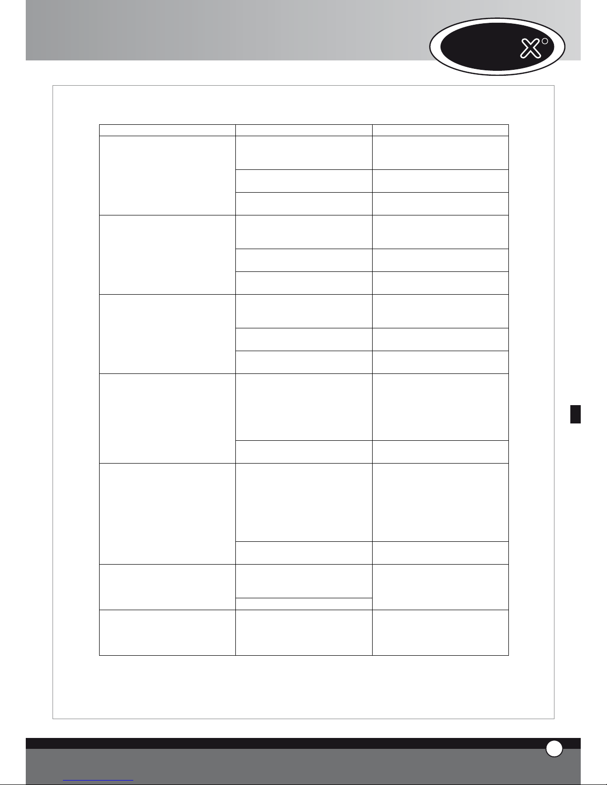
10. MESSAGGI ERRORE
10.1 MESSAGGI ERRORE FORNO
GUASTO CAUSA RIMEDIO
Fili di collegamento della sonda
camera 1 staccati dalla scheda di
potenza
Rivolgersi ad un tecnico
specializzato per la riparazione
Sonda camera 1 danneggiata
Rivolgersi ad un tecnico
specializzato per la riparazione
Sul display 1 appare
costantemente la scritta EF1
Scheda potenza forno danneggiata
Rivolgersi ad un tecnico
specializzato per la riparazione
Fili di collegamento della sonda
camera 2 staccati dalla scheda di
potenza
Rivolgersi ad un tecnico
specializzato per la riparazione
Sonda camera 2 danneggiata
Rivolgersi ad un tecnico
specializzato per la riparazione
Sul display 1 appare
costantemente la scritta EF2
Scheda potenza forno danneggiata
Rivolgersi ad un tecnico
specializzato per la riparazione
Fili di collegamento della sonda
cuore staccati dalla scheda di
potenza
Rivolgersi ad un tecnico
specializzato per la riparazione
Sonda cuore danneggiata
Rivolgersi ad un tecnico
specializzato per la riparazione
Sul display 1 appare
costantemente la scritta EF3
Scheda potenza forno danneggiata
Rivolgersi ad un tecnico
specializzato per la riparazione
Intervento del protettore termico
di un motore
Togliere tensione al forno,
aspettare che si raffreddi e fornire
nuovamente tensione: se compare
nuovamente la scritta EF4
rivolgersi ad un tecnico
specializzato per la riparazione
Sul display 1 appare
costantemente la scritta EF4
Scheda potenza forno danneggiata
Rivolgersi ad un tecnico
specializzato per la riparazione
Intervento del dispositivo termico
di sicurezza
Togliere tensione al forno,
aspettare che si raffreddi,
ripristinare il dispositivo termico e
fornire nuovamente tensione: se
compare nuovamente la scritta
EF5 rivolgersi ad un tecnico
specializzato per la riparazione
Sul display 1 appare
costantemente la scritta EF5
Scheda potenza forno danneggiata
Rivolgersi ad un tecnico
specializzato per la riparazione
Cavo collegamento scheda
controllo / scheda potenza
danneggiato o staccato
Sul display 1 appare
costantemente la scritta EF6
Scheda potenza forno danneggiata
Rivolgersi ad un tecnico
specializzato per la riparazione
Sul display 1 appare
costantemente la scritta EF7
Perdita di comunicazione tra
forno ed accessori.
Rivolgersi ad un tecnico
specializzato per la riparazione
*: La sonda camera 1 è la sonda posteriore (quella più vicina al carter aria) mentre la sonda camera 2 è quella anteriore (quella più
vicina alla porta).
UNO
R
14
ITALIANO
Page 80

10.2 MESSAGGI ERRORE ABBATTITORE TEMPERATURA
GUASTO CAUSA RIMEDIO
Fili di collegamento della sonda
camera staccati dalla scheda di
potenza
Rivolgersi ad un tecnico
specializzato per la riparazione
Sonda camera danneggiata
Rivolgersi ad un tecnico
specializzato per la riparazione
Sul display1 appare
costantemente la scritta EA1
Scheda potenza abbattitore
danneggiata
Rivolgersi ad un tecnico
specializzato per la riparazione
Fili di collegamento della sonda
cuore staccati dalla scheda di
potenza
Rivolgersi ad un tecnico
specializzato per la riparazione
Sonda cuore danneggiata
Rivolgersi ad un tecnico
specializzato per la riparazione
Sul display 1 appare
costantemente la scritta EA2
Scheda potenza abbattitore
danneggiata
Rivolgersi ad un tecnico
specializzato per la riparazione
Sovra pressione circuito
frigorifero
Togliere tensione all’abbattitore,
attendere una ventina di minuti e
fornire nuovamente tensione: se
compare nuovamente la scritta
EA3 rivolgersi ad un tecnico
specializzato per la riparazione
Sul display 1 appare
costantemente la scritta EA3
Scheda potenza abbattitore
danneggiata
Rivolgersi ad un tecnico
specializzato per la riparazione
Sul display 1 appare
costantemente la scritta EA4
Limite funzionamento filtri Estrarre il filtro e lavarlo
Cavo collegamento forno /
abbattitore danneggiato o staccato
Sul display 1 appare
costantemente la scritta EA5
Scheda potenza abbattitore
danneggiata
Rivolgersi ad un tecnico
specializzato per la riparazione
10.3 MESSAGGI ERRORE MANTENITORE
GUASTO CAUSA RIMEDIO
Fili di collegamento della sonda
camera staccati dalla scheda di
potenza
Rivolgersi ad un tecnico
specializzato per la riparazione
Sonda camera danneggiata
Rivolgersi ad un tecnico
specializzato per la riparazione
Sul display 1 appare
costantemente la scritta EL1
Scheda potenza mantenitore
danneggiata
Rivolgersi ad un tecnico
specializzato per la riparazione
Fili di collegamento della sonda
umidità staccati dalla scheda di
potenza
Rivolgersi ad un tecnico
specializzato per la riparazione
Sonda umidità danneggiata
Rivolgersi ad un tecnico
specializzato per la riparazione
Sul display 1 appare
costantemente la scritta EL2
Scheda potenza mantenitore
danneggiata
Rivolgersi ad un tecnico
specializzato per la riparazione
Cavo collegamento forno /
mantenitore danneggiato o
staccato
Sul display 1 appare
costantemente la scritta EL3
Scheda potenza mantenitore
danneggiata
Rivolgersi ad un tecnico
specializzato per la riparazione
15
ITALIANO
ChefTop™ - BakerTop™
Page 81

10.4 MESSAGGI ERRORE CAPPA
GUASTO CAUSA RIMEDIO
Fili di collegamento della sonda
temperatura staccati dalla scheda
di potenza
Rivolgersi ad un tecnico
specializzato per la riparazione
Sonda temperatura danneggiata
Rivolgersi ad un tecnico
specializzato per la riparazione
Sul display 1 appare
costantemente la scritta EC1
Scheda potenza cappa danneggiata
Rivolgersi ad un tecnico
specializzato per la riparazione
Cavo collegamento forno / cappa
danneggiato o staccato
Sul display 1 appare
costantemente la scritta EC2
Scheda potenza cappa danneggiata
Rivolgersi ad un tecnico
specializzato per la riparazione
10.5 MESSAGGI ERRORE SISTEMA OSMOSI
GUASTO CAUSA RIMEDIO
Trasduttore di pressione
danneggiato
Cavo di collegamento trasduttore
/ scheda danneggiato o staccato
Sul display 1 appare
costantemente la scritta EO1
Scheda potenza osmosi
danneggiata
Rivolgersi ad un tecnico
specializzato per la riparazione
Contalitri danneggiato
Cavo di collegamento contalitri /
scheda danneggiato o staccato
Sul display 1 appare
costantemente la scritta EO2
Scheda potenza osmosi
danneggiata
Rivolgersi ad un tecnico
specializzato per la riparazione
Sul display 1 appare
costantemente la scritta EO3
Limite funzionamento filtri
Rivolgersi ad un tecnico
specializzato per la sostituzione
Sul display 1 appare
costantemente la scritta EO4
Pressione acqua in ingresso
troppo bassa
Verificare che arrivi acqua
all’ingresso dell’osmosi
Cavo collegamento forno / osmosi
danneggiato o staccato
Sul display 1 appare
costantemente la scritta EO5
Scheda potenza osmosi
danneggiata
Rivolgersi ad un tecnico
specializzato per la riparazione
UNO
R
16
ITALIANO
Page 82

B. ISTRUZIONI PER
L’INSTALLATORE
1. AVVERTENZA
Tutte le operazioni di installazione, montaggio, assistenza
e manutenzione devono essere eseguite da personale
qualificato secondo le norme in vigore.
Leggere attentamente il manuale prima dell’installazione
e della messa in funzione dell’apparecchio.
Verificare l’integrità dell’apparecchio (controllare
eventuali danno da trasporto). Togliere dalla camera di
cottura tutto il materiale informativo.
2. OPERAZIONI PRELIMINARI
2.1 LUOGO DI INSTALLAZIONE
Prima di posizionare l’apparecchio verificare le misure
d’ingombro e l’esatta posizione dei collegamenti elettrici,
idrici, scarico fumi secondo le figure riportate nell’allegato
fascicolo “Dati Tecnici”.
Non installare il forno in zone a rischio esplosioni.
Non installare il forno in ambienti esterni senza una
completa ed adeguata protezione per la pioggia.
Non installare ne utilizzare il forno in ambienti piccoli e
chiusi senza un sufficiente ricambio d’aria.
2.2 PREDISPOSIZIONE PER IL POSIZIONAMENTO
I piedini sono posti all’interno del forno e devono essere
tassativamente montati.
Non utilizzare il forno senza piedini.
Rimuovere il cassetto raccogligocce dalla schiena utilizzando un cacciavite.
Posizionare il forno su un fianco.
Inserire i piedini e le guide cassetto come indicato nella
foto.
2.3 RIMOZIONE PELLICOLE DI PROTEZIONE
Togliere completamente la pellicola protettiva dalle
pareti esterne dell’apparecchio con attenzione ed evitare
che rimangano residui di colla.
Se nonostante ciò dovessero rimanervi ancora residui di
colla toglierli con un solvente appropriato.
Rimuovere la protezione puntale sonda.
2.4 POSIZIONAMENTO
Posizionare l’apparecchio rispettando le norme di
sicurezza indicate qui di seguito.
Posizionare l’apparecchio in modo che la parete posteri-
17
ITALIANO
ChefTop™ - BakerTop™
Page 83

ore sia facilmente accessibile per effettuare l’allacciamento
elettrico e per consentire la manutenzione.
L’apparecchio non è adatto all’incasso e al posizionamento in batteria.
Si consiglia di lasciare una distanza di 5 cm tutto attorno
all’apparecchio.
Con particolare riferimento ai forni, tutti i modelli devono
essere posizionati sopra un supporto tipo lievitatore,
porta-teglie, oppure sopra un tavolo.
Non installare i forni in prossimità di altre fonti di calore.
Non installare i forni sul pavimento.
Se l’apparecchio é posizionato vicino a pareti, divisori,
mobili da cucina, bordure decorate ecc., si raccomanda
che questi siano di materiale non infiammabile.
In caso contrario devono essere rivestiti con materiale
isolante termico non infiammabile, e occorre prestare la
massima attenzione alle norme di prevenzione incendi.
Non installare l’apparecchio nelle vicinanze di una friggitrice in quanto depositi di grasso potrebbero entrare
all’interno del forno e depositarsi su parti elettriche
causando malfunzionamenti Non installare l’apparecchio
vicino a contenitori di sostanze infiammabili come
bombole di gas.
Non installare l’apparecchio nelle vicinanze di una
friggitrice.
Nel caso in cui, una volta posizionato il forno la maniglia
della porta non dovesse rimanere correttamente chiusa
(fig.1), probabilmente occorre adattare lo scrocco di
chiusura; procedere come segue:
• con la porta del forno aperta (fig.2), allentare leggermente le viti di fissaggio dello scrocco (fig.3)
• richiudere la porta e girare la maniglia per bloccarne
l’apertura(fig.3)
• se la porta rimane chiusa con la maniglia perfettamente in posizione verticale, riaprire la porta (fig.4) e
fissare energicamente le viti di fissaggio dello scrocco definitivamente (fig.5).
• Se il problema continua a persistere ripetere la
sequenza provando ad allentare maggiormente le viti di
fissaggio dello scrocco.
Attenzione! Un superficie d’appoggio del forno non
perfettamente piana, non permette alla maniglia della
porta di chiudersi perfettamente: se la deformazione
del piano è lieve, si può ovviare al problema adattando
lo scrocco di chiusura applicando il metodo precedentemente descritto; non è possibile compensare il problema
in caso di forti deformazioni del piano o disuniformità
della superficie d’appoggio del forno.
Verificare che l’apparecchio sia installato in piano.
3. ALLACCIAMENTO ELETTRICO
3.1 AVVERTENZA
Il collegamento alla rete d’alimentazione elettrica deve
essere effettuato secondo le normative vigenti.
Prima di effettuare il collegamento accertarsi che la
tensione e la frequenza corrispondano a quanto riportato
sulla targhetta apposta sull’apparecchio.
L’apparecchio deve essere posto in modo che la spina di
connessione alla rete sia accessibile (per gli apparecchi
dotati si spina Schuko).
Interporre tra l’apparecchiatura e la rete, un interruttore di disconnessone omnipolare accessibile dopo
UNO
R
18
ITALIANO
Fig. 1 Fig. 2
Fig. 3 Fig. 4
Fig. 5 Fig. 6
Page 84

l’installazione, i cui contatti abbiano una distanza minima
d’apertura di 3 mm, di portata appropriata (ad es.: interruttore magnetotermico) con categoria di isolamento
pari a 4000V.
Si consiglia l’impiego di un interruttore di sicurezza per
correnti di guasto.
La tensione di alimentazione, quando l’apparecchio è in
funzione, non deve discostarsi dal valore della tensione
nominale, riportata sulla targhetta dati dell’apparecchio,
di ± 10%.
3.2 COLLEGAMENTO RETE ALIMENTAZIONE
ELETTRICA
1- Forni dotati di cavo e spina Schuko (monofase 230V): è
sufficiente inserire la spina nell’apposita presa (la presa
deve essere adatta alla spina fornita in dotazione)
2- Forni dotati di cavo (trifase 400V + Neutro): i forni in
questione sono dotati di cavo elettrico a 5 conduttori;
è quindi necessario collegare il cavo direttamente ad
un quadro elettrico. Per effettuare gli altri tipi di collegamento previsti è necessario sostituire il cavo. Vedere
l’allegato “Dati tecnici” per l’impiego dei cavi adatti. Gli
schemi di collegamento si trovano nella parte interna
del coperchio della morsettiera.
La sostituzione del cavo deve essere eseguita da personale
autorizzato.
Per sostituire il cavo di alimentazione procedere come
segue:
Aprire il coperchio della morsettiera svitando la vite
di fissaggio
Collegare i conduttori secondo lo schema di collegamento scelto
Fissare il cavo mediante l’apposito ferma cavo
Chiudere il coperchio della morsettiera e serrare la
vite di fissaggio
AVVERTENZA
Effettuare il collegamento della morsettiera come indicato
•
•
•
•
dal disegno: inserire il ponte di rame e il cavo elettrico
insieme sotto la vite, nel senso di avvitamento, in modo
che serrando la vite, il cavo e il ponte siano strettamente
fissati.
Un collegamento errato può causare il surriscaldamento
della morsettiera, fino a farla fondere.
L’apparecchio deve essere connessa alla linea di terra
della rete.
La presa di alimentazione dovrà essere in ottime condizioni e collocata in un punto pulito distante da oli, grassi
o altre sostanze che possono compromettere una buona
connessione elettrica.
3.3 COLLEGAMENTO EQUIPOTENZIALE
L’apparecchio deve essere incluso in un sistema equipotenziale la cui efficacia deve essere opportunamente
verificata secondo quanto riportato nella normativa in
vigore. Questo collegamento deve essere effettuato tra
apparecchiature diverse con il morsetto contrassegnato
dal simbolo : simbolo morsetto equipotenziale
Il conduttore equipotenziale deve avere una sezione
minima di 10 mm2.
4. ALLACCIAMENTO IDRICO
4.1 AVVERTENZE
E’ necessario interporre tra la rete idrica e l’apparecchio
un rubinetto di intercettazione e un filtro meccanico.
L’apparecchio è fornito con 2 metri di tubo e relativo
raccordo (3/4”) con valvola di non ritorno e filtro
meccanico come richiesto dalle normative vigenti.
Prima di collegare il tubo acqua all’apparecchio far defluire
dell’acqua per eliminare eventuali residui.
L’acqua in ingresso deve avere un valore di pressione
compreso tra 150 e 200 kPa e una temperatura massima
di 30 °C. Se la pressione dell’acqua in ingresso ha un valore
superiore ai 2 bar è necessario installare un riduttore di
pressione tarato a 2 bar.
4.2 TRATTAMENTO ACQUA
L’acqua deve avere una durezza massima di 5 °F (questo per
ridurre il formarsi di calcare all’interno della camera di cottura).
19
ITALIANO
ChefTop™ - BakerTop™
Page 85

E’ vivamente consigliato l’uso di un apparecchio demineralizzatore (osmosi inversa) onde evitare il deposito di
calcare e/o altri minerali all’interno del forno.
A tal proposito è a Vostra disposizione il sistema di osmosi
inversa UNOX codice XC224 direttamente gestito con
un sistema di autodiagnosi dal controllo elettronico del
forno.
5. COLLEGAMENTO SCARICHI
5.1 AVVERTENZE
L’acqua in uscita dallo scarico del forno può raggiungere
temperature elevate (90 °C).
I tubi utilizzati per lo scarico dell’acqua devono essere in
grado di sopportare tali temperature.
5.2 ACQUA SCARICO
Il tubo acqua di scarico si trova nella parte posteriore
del forno e va collegato con un tubo rigido o flessibile
(vedere kit UNOX codice TB15200A) e convogliato
ad uno scarico aperto o sifonato; il suo diametro non
deve essere inferiore a quello dell’attacco di scarico e la
lunghezza non superiore ad un metro.
Evitare strozzature su condotte flessibili o gomiti per
condotta metalliche, lungo tutto il percorso di scarico.
Il tubo di scarico deve rimanere almeno 20 cm al di sotto
dell’attacco scarico, per facilitare il deflusso.
5.3 SCARICO FUMI CAMERA COTTURA
Lo scarico fumi camera di cottura si trova nella parte posteriore in alto del forno.
Non sovrapporre oggetti e/o materiali sopra allo scarico
fumi in modo tale da garantire il normale deflusso dei fumi.
Accertarsi che sopra lo scarico fumi non siano presenti
oggetti e/o materiali che possono venire danneggiati dai
fumi stessi.
Si consiglia pertanto di posizionare il forno sotto ad una
cappa di aspirazione o di installare la cappa di aspirazione
fumi UNOX codice XC314 per ChefTop™ - XC414 per
BakerTop™ o il condensatore di vapori UNOX codice
XC114 o comunque di convogliare fumi a mezzo tubo
UNOX codice TB1520A0 evitando strozzature.
6. COLLEGAMENTO ACCESSORI (LIEVITATORE, CAPPA, ABBATTITORE TEMPERATURA ECC.)
La scheda di controllo del forno gestisce tutti gli accessori
(cappa, mantenitore, abbattitore temperatura, sistema
osmosi). Gli accessori gestiti dal forno si collegano al
forno stesso mediante i connettori RJ45 posti sul retro
del forno.
Per collegare i cavi procedere come segue:
• Rimuovere la lamiera posteriore per aver accesso
all’impianto elettrico interno
• Praticare con un cutter una feritoia verticale su uno dei
tappi in gomma situati sul pannello dietro al forno
• Introdurre attraverso la feritoia un terminale del cavo RJ45
• inserire il terminale del cavo nell’apposito connettore
femmina presente sulla scheda di potenza (non ha importanza quale dei tre connettori viene utilizzato)
• rimontare il coperchio di protezione serrando le
apposite viti;
In questo modo l’accessorio è riconosciuto e connesso
al forno.
Per il funzionamento e l’utilizzo degli accessori vedere il
libretto di istruzioni dell’accessorio in questione.
UNO
R
20
ITALIANO
Page 86

7. SOSTITUZIONE VETRI PORTA
7.1 AVVERTENZA
Il vetro interno di cui è costituita la porta è un vetro
temprato basso emissivo.
Una delle due superfici di tale vetro, infatti, è ricoperta
da un film metallico trasparente che limita il passaggio di
calore nell’intercapedine tra i due vetri della porta e lo
riflette all’interno della camera di cottura.
La sostituzione del vetro deve essere effettuata tenendo
in considerazione questa caratteristica, cioè la superficie
basso emissiva dovrà essere rivolta verso la camera di
cottura.
In caso contrario si avrebbe un aumento della temperatura della superficie esterna della porta aumentando il
rischio di scottature da parte dell’utente o dello scoppio
del vetro stesso.
Il controllo deve essere effettuato tramite un tester
impostato ad una portata massima di 2 KOhm. Appoggiando sulla superficie del vetro i puntali ad una distanza
di circa 5 cm, il lato basso emissivo risulterà avere una
resistenza di circa 50 Ohm, mentre sull’altro, il tester
indicherà resistenza infinita.
8. SOVRAPPOSIZIONE FORNI
Nel caso di sovrapposizione di più forni è obbligatorio
l’utilizzo del kit di sovrapposizione UNOX codice XC680
per ChefTop™- XC 681 per BakerTop™ che mantiene
la corretta distanza tra i due forni.
E’ a disposizione anche il kit per il collegamento alimentazione acqua, acque di scarico e scarico fumi XC615.
C. CERTIFICAZIONI
Costruttore: UNOX S.p.A.
Indirizzo: Via Dell’Artigianato 28/30
I-35010 Vigodarzere, Padova, Italy
Prodotto: Forno ventilato convezione vapore per
utilizzi professionali
Famiglia: ChefTop™ - BakerTop™
NORMATIVE DI RIFERIMENTO
La marcatura “CE” riportata sulle apparecchiature inserite in
questo manuale fa riferimento alle seguenti direttive:
FORNI COMBINATI CONVEZIONE VAPORE
ELETTRICI - SERIE XVC - XBC:
Direttiva Bassa Tensione 2006/95/CE
secondo le norme:
EN 60335-2-42:2003
EN 60335-1:2002; A11; A1; A12 ; A2 including possible
listed national conditions/deviations for Norway.
Direttiva Compatibilità Elettromagnetica 2004/108/CE
secondo le norme:
EN 55014-1:2000; A1; A2
EN 61000-3-2:2000; A2
EN 61000-3-3:1995; A1; A2
EN 61000-3-11:2000
EN 55014-2:1997; A1
EN 50366:2003 ; A1
TARGHETTA DATI
•
•
•
•
•
•
•
•
21
ITALIANO
ChefTop™ - BakerTop™
Page 87

UNO
R
22
ITALIANO
Bakertop™
ChefTop
™
www.unox.com
www.unox.com
BakerTop
™
Page 88

INTRODUCCION
Estimado Cliente, le agradecemos y lo felicitamos por haber adquirido un horno de la línea ChefTop™ - Baker-
Top™ y deseamos que este sea el inicio de una positiva y
duradera relación.
Como Ud. conocerá la línea de hornos ChefTop™ -
BakerTop™, y todos los aparatos complementarios a
ella (abatidor, armario termico, bandejas y parrillas especiales), han sido estudiados para permitirle completar
cualquier proceso de cocción, desde el más simple al más
complejo.
El innovativo panel de control digital ChefTouch -
BakerTouch le permitirá comandar, con un único control, todos los aparatos UNOX conectados al horno.
Sin duda, la novedad más importante a señalar son las
“COCCIONES AUTOMATICAS ChefUnox - BakerUnox
que le permitirán cocer una infinita gama de alimentos sin
tener que introducir los parámetros tiempo, temperatura
en la cámara y temperatura en el corazón.
Con sólo seleccionar el tipo de cocción deseado, entre
los siguientes: SLOW, STEAM, ROAST, GRILL, ChefUnox
- BakerUnox cocinará por Ud. exquisitos y suculentos
platos.
Además de la función de cocción automática se tendrá la
posibilidad de elegir entre las seis cocciones automáti-
cas por familia de productos: BAKE, BREAD, POLLO, PIZZA
ITALY, PIZZA, FRIES.
La utilización de una o dos sondas al corazón suplementarias, dotadas de agujas extra finas y externas al horno, le
permitirán además efectuar perfectas cocciones al vacío y
perfectas cocciones al vapor de alimentos particularmente delicados o de pequeñas dimensiones.
Siempre el chef sigue siendo la figura más importante.
Dentro de cada tipo de cocción automática encontrará
la posibilidad de personalizar algunos parámetros para
alcanzar, en base a vuestras exigencias personales, el dorado y el grado de cocción que se consideren óptimos.
Indice:
A. Instrucciones para la utilización Page 02
1. ADVERTENCIA Page 02
2. LIMPIEZA DEL HORNO Page 02
3. PANEL DE MANDO ChefTouch - BakerTouch Page 03
4. PRINCIPIOS DE COCCION Page 09
5. COMUNICACION CON
EL MUNDO EXTERNO Page 11
6. MANUTENCION ORDINARIA Page 12
7. MANUTENCION EXTRAORDINARIA Page 12
8. APAGADO EN CASO DE AVERIA Page 12
9. AVERIAS MAS FRECUENTES Page 13
10. MENSAJES DE ERRORES Page 14
B. Instrucciones para la instalación Page 17
1. ADVERTENCIA Page 17
2. OPERACIONES PRELIMINARES Page 17
3. CONEXION ELECTRICA Page 18
4. CONEXION HIDRICA Page 19
5. CONEXION DEL DESAGÜE Page 20
6. CONEXION DE ACCESORIOS Page 20
7. SUSTITUCION DEL CRISTAL DE LA PUERTA Page 21
8. SOBREPOSICION DE HORNOS Page 21
C. Certificaciones Page 21
1
ESPAÑOL
ChefTop™ - BakerTop™
Page 89

A. INSTRUCCIONES PARA LA
UTILIZACION
1. ADVERTENCIA
ATENCION:
Leer atentamente el presente libreto, contiene importantes indicaciones referentes a la seguridad y uso del
horno.
Conservar cuidadosamente este manual para posteriores
consultas de los operadores.
El aparato debe ser destinado solamente al uso para el
cual ha estado expresamente concebido, cualquier otro
utilizo se considera inadecuado.
Los aparatos pueden ser utilizados para los siguentes
usos:
para la cocción de todos los productos de pastelería y
panadería, sean frescos o congelados;
para la cocción de todos los productos de gastronomía, sean frescos o congelados;
para la regeneración de comidas refrigeradas o congeladas;
para la cocción al vapor de carnes, pescados y verduras.
En la primera utilización asegurarse que en el interior de
la cámara de cocción no haya manuales de instrucción,
bolsas de plástico u otros.
Los paneles de mando solo pueden ser accionados con
los dedos; cualquier otro objeto puede provocar daños
y/o malfuncionamiento; y por lo tanto hace decaer la garantía.
El aparato está destinado para uso profesional específico
y debe ser utilizado por personal calificado.
El aparato no es adecuado para ser utilizado por personas (niños incluidos) con reducidas capacidades físicas,
mentales y sensoriales, o sin experiencia y conocimientos,
a menos que hayan sido instruidos acerca de la correcta
utilización del producto por una persona responsable de
su seguridad.
Asegúrese de que los niños no juegan con el aparato.
La temperatura de las partes externas puede superar los
60 °C.
Evitar posicionar fuentes de calor cerca del aparato.
En el caso de cocer productos extremadamente grasos
colocar un contenedor en la parte inferior de la cámara
de cocción.
En el caso de extracción de bandejas que contengan
líquidos calientes prestar particular atención a eventuales
derrames de los líquidos.
En el caso que la bandeja contenga productos líquidos
calientes es necesario que la bandeja este posicionada a
•
•
•
•
una altura tal que sea visible por el operador.
Prestar particular atención a los movimientos de los contenedores de comida durante y luego la cocción: las temperaturas pueden ser elevadas y provocar quemaduras.
Abrir lentamente la puerta: existe peligro de ustiones por
la salida de vapores a alta temperatura.
Utilizar el horno con una temperatura ambiente comprendida entre +5 °C y +35 °C.
SONDA AL CORAZON
Atención al uso de la sonda al corazón en el interior
del horno, puede provocar ustiones: utilizar adecuados guantes de protección.
No dejar colgando la sonda al corazón fuera de la
puerta.
Quitar la sonda de los alimentos antes de extraer la
bandeja
Durante el funcionamiento del programa “COOL” (enfriamiento de la cámara) las turbinas del horno funcionan con
la puerta abierta.
Las operaciones de instalación, manutención y reparación
deben ser realizadas por personal calificado y adecuadamente entrenado. Antes de realizar tales operaciones
desconectar la tensión de alimentación del aparato.
En el caso que el aparato sea posicionado sobre un soporte o mesa dotada de ruedas asegurarse que el movimiento no vaya a dañar cables eléctricos, tuberías de
agua, tuberías de descarga u otros.
Evitar realizar la saladura de los alimentos en la cámera
de cocción.
Evite el sobrecalentamiento de los alimentos tales como
aceites, grasas y similares, existe riesgo de incendio.
No ponga en el interior del horno materiales termo-perecederos, como plástico o madera.
2. LIMPIEZA DEL HORNO
ADVERTENCIA:
Antes de efectuar cualquier operación de manutención o
limpieza es necesario desconectar la alimentación eléctrica y esperar que el aparato se enfríe.
2.1 PRIMERA UTILIZACION DEL HORNO
Antes de la primera utilización del aparato: limpiar la parte de metal con agua caliente y jabón , y posteriormente
enjuagarla. No lavar jamás el interior de la cámara con
ácidos o productos agresivos.
Calentar el horno vacío por 30 minutos aproximadamente a la temperatura de 200°C (392°F) para eliminar eventuales olores del aislamiento térmico.
•
•
•
UNO
R
2
ESPAÑOL
Page 90

2.2 LIMPIEZA EN LA CAMARA DE COCCION
Se aconseja limpiar cotidianamente la cámara de cocción para mantener niveles de higiene elevados y para evitar que el acero
inoxidable en el interior de la cámara de cocción se deteriore. A tal propósito se aconseja la utilización del sistema de lavado
Rotor.KLEAN™ código XC404 que permite realizar la limpieza automática de la cámara de cocción.
Para la limpieza manual de la cámara de cocción no utilizar los siguientes instrumentos:
lanzas a alta presión
productos ácidos
productos /instrumentos abrasivos
Para la limpieza manual de la cámara de cocción utilizar el siguientes instrumentos:
encender el horno
programar la temperatura a 80°C y el vapor al 100%
dejar funcionar el horno por diez minutos
dejar enfriar y limpiar con un paño
En el caso que en el interior de la cámara de cocción haya presente residuos grasos, los mismos pueden prenderse fuego.
2.3 LIMPIEZA EXTERNA DEL HORNO
No utilizar un chorro de agua con presión para el lavado externo del horno.
Utilizar paños húmedos.
3. PANEL DE MANDO ChefTouch - BakerTouch
3.1 FUNCIONAMIENTO DEL CONTROL ChefTouch - BakerTouch
El control “ChefTouch” - “BakerTouch” funciona acercando el dedo al pulsante serigrafiado (utilizar exclusivamente los
dedos y no otros objetos como cuchillos, tenedores, etc). De esta manera se pueden activar las funciones y / o programar los
valores deseados. La ventaja de tal tecnología es que elimina cualquier movimiento mecánico garantizando por lo tanto un alto
grado de fiabilidad. Tal tipo de tecnología permite además una rápida y fácil limpieza del panel de mando.
3.2 LAYOUT DEL PANEL DE MANDO
1 2 43
3.3 ENCENDIDO / APAGADO
Cuando se suministra la tensión al horno, el control se enciende automaticamente.
Después de 15 minutos que no se acciona ningún pulsante y que no hay algún aparato en funcionamiento (hornos, abatidor de
temperatura, armario termico) el control electrónico va en stand by: permanece encendido solo el led “START / STOP”.
Para reactivar el control electrónico es suficiente pulsar el pulsante .
Con el control electrónico encendido, teniendo presionado el pulsante por 6 segundos el control electrónico va en stand
by; para reactivarlo se presiona nuevamente el pulsante .
•
•
•
•
•
•
•
3
ESPAÑOL
ChefTop™ - BakerTop™
Page 91

3.4 LOGICA DE FUNCIONAMIENTO DE LAS LUCES
DE LA CAMARA
Las luces normalmente permanecen apagadas; se encienden por 1 minuto cuando se presiona un pulsante cualquiera y luego se apagan. Para reactivarlas es suficiente
presionar un pulsante cualquiera.
3.5 FUNCIONAMIENTO MANUAL
Cada cocción puede estar compuesta por 4 fases.
Para pasar de una fase a otra se debe tocar el pulsante
y la fase activa se visualiza a través del led encendido.
Para cada fase el usuario puede programar los siguientes
parámetros:
tiempo o en alternativa temperatura al corazón
temperatura en la cámara o, en alternativa, Delta T (disponible solo si se programa la temperatura al corazón)
clima en el interior de la cámara de cocción (STEAM.
Maxi / DRY.Maxi)
Para pasar de un parámetro a otro se utiliza el pulsante .
El parámetro activo se visualiza mediante uno de los cinco iconos luminosos
T
TIME
CORE
TEMPERATURE
CAVITY
TEMPERATURE
DELTA T
CLIMA
LUX
CLIMA LUX
Tiempo
temperatura al
corazón
temperatura en
camara
Delta T CLIMA
LUX
El parámetro tiempo y temperatura al corazón son mutuamente excluyentes: si se programa el tiempo, el parámetro temperatura al corazón se saltea, si se programa la
temperatura al corazón el parámetro tiempo se saltea.
El parámetro temperatura en la cámara y Delta T son
•
•
•
mutuamente excluyentes: si se programa la temperatura
en la cámara el parámetro Delta T se saltea, si se programa el
Delta T el parámetro temperatura en la cámara se saltea.
Es necesario programar el parámetro tiempo o el parámetro temperatura al corazón: si ninguno de tales parámetros se programa el control no permite programar los parámetros sucesivos (temperatura en la cámara, Delta T, Clima)
Programación del tiempo
El tiempo se visualiza mediante el display 1 en horas.minutos y se programa mediante los pulsantes .
Cuando en el display aparece la escritura “INF” el horno funciona hasta que no es detenido manualmente por
el usuario. Cuando en los step o fases de cocción 2,3
o 4, se selecciona la función HOLD “HLD” las turbinas
funcionan solo cuando las resistencias están encendidas.
Con cada funcionamiento de las turbinas se invierte el
sentido de rotación.
STEP 1
0h 00' 9h 59'
inF
Programación de la temperatura en
el corazón
La temperatura en el corazón se visualiza mediante el display 1 y se programa mediante los pulsantes .
Cuando en el corazón se alcanza la temperatura programada, la fase de cocción se considera concluída y se pasa
a la fase de cocción sucesiva (si se ha programado).
Está disponible el kit de sondas al corazón externas
XC240 para poder conectar una ulterior sonda al corazón de dimensiones reducidas, adecuada para cocer al
vacío y para cocer productos de tamaño pequeño.
0°C 100°C
UNO
R
4
ESPAÑOL
Page 92

Programación de temperatura en la
cámara
La temperatura en el interior de la cámara se visualiza
mediante el display 2 y se programa mediante los pulsan-
tes
260°C0°C
Programación Delta T
El valor del Delta T se visualiza mediante el display 2 y se
programa mediante los pulsantes
0°C 100°C
CLIMA LUX - Programación del Clima
La programación del clima (STEAM.Maxi™ / DRY.Maxi™)
en el interior de la cámara de cocción se visualiza mediante
la elipse CLIMA LUX y se programa mediante los pulsantes
Los 10 led de color azul indican el porcentaje de vapor en el
interior de la cámara de cocción (STEAM.Maxi™); los 10 led
de color rojo indican el porcentaje de secado (DRY.Maxi™).
STEAM
Maxi
DRY
Maxi
Puesta en funcionamiento / inte
rrupción de la cocción
Para poner en funcionamiento una cocción es necesario
presionar el pulsante .
La puesta en funcionamiento de la cocción se indica
cuando se enciende el led “START STOP” .
Para detener la cocción es necesario presionar nuevamente el pulsante .
Cuando se termina un ciclo de cocción sea en modalidad
manual que en modalidad programada, el horno emite
una señal acústica por 15 segundos y el display 1 parpadea por 45 segundos. Durante estos 45 segundos el led
“START / STOP” permanece encendido:
si se presiona el pulsante el tiempo se incrementa y el horno automaticamente comienza a funcionar
(con los parámetros de funcionamiento relativos a la
última fase de cocción realizada)
si se presiona el pulsante el led “START / STOP”
se apaga y todos los parámetros de funcionamiento
se resetean.
si no se presiona algún pulsante,transcurridos los 45
segundos, el led “START / STOP” se apaga y todos
los parámetros de funcionamiento se resetean.
Al finalizar un ciclo de cocción, en modalidad manual o
programada, presionando el pulsante “P” en el display a 5
carácteres aparece la escritura “LASTP”: presionando el
pulsante “START / STOP” se inicia nuevamente el último
ciclo de cocción que había sido realizado.
3.6
Funcionamiento con programas
LPUMP
L3
L2
L1
P01
P70
P02
P00
COOL
El control electrónico permite al usuario memorizar, y
utilizar sucesivamente, hasta 70 programas de cocción.
El control electrónico contiene , en su interior, el programa de enfriamiento COOL y los programas para el lavado
de la cámara de cocción (L1, L2, L3, LH2O), si el sistema
de lavado XC404 está instalado.
•
•
•
5
ESPAÑOL
ChefTop™ - BakerTop™
Page 93
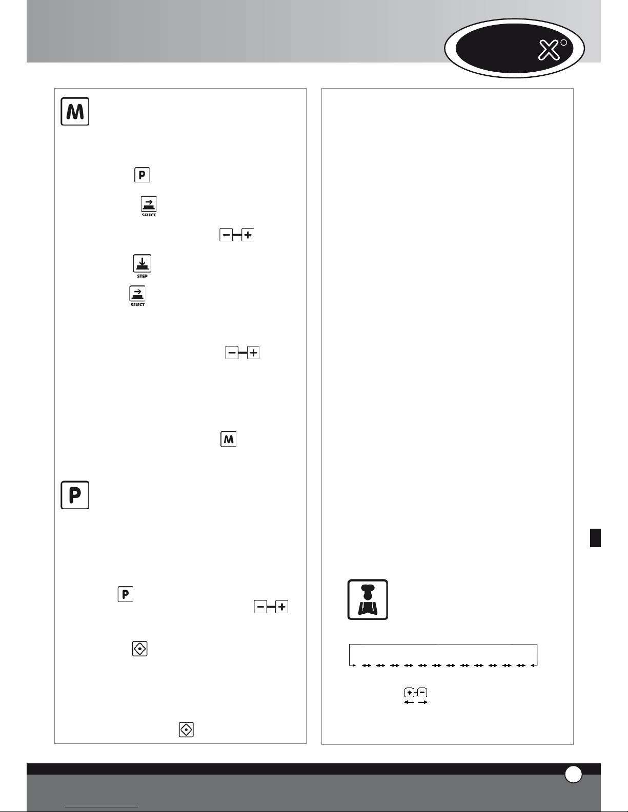
Memorización de los programas por
parte del usuario
Para memorizar un programa proceder como se indica:
se entra en la modalidad programa presionando el
pulsante
en el primer display aparece la escritura “Prg”, con
el pulsante es posible seleccionar cual de los
5 carácteres se quiere modificar; la modificación es
posible mediante los pulsantes
en el primer display a izquierda, luego de presionar el
pulsante , aparece la escritura “PRE” y todos
los 4 led de los step resultan apagados. Mediante el
pulsante se selecciona si programar la temperatura como un valor absoluto o como un diferencial,
(se enciende el icona luminoso de la temperatura de
la cámara o el icona luminoso del Delta T) y se programa el
valor deseado mediante los pulsantes
.
se programan los parámetros de funcionamiento
(tiempo, temperatura en el corazón, temperatura en
la cámara, Delta T, clima); como en el funcionamiento
manual, cada programa de cocción puede estar compuesto desde 1 a 4 fases
se tiene presionado el pulsante por 5 segundos
para la memorización del programa (cuando finalizan
los 5 segundos se emite un sonido de confirmación).
Utilización de los programas memorizados por el usuario, programa de
enfriamiento y programas de lavado
Para llamar un programa memorizado por el usuario, el
programa de enfriamento o un programa de lavado proceder como se indica:
se entra en modalidad programa presionando el pulsante
se selecciona mediante los pulsantes el
número del programa que se quiere utilizar
se pone en funcionamiento el programa mediante el
pulsante
la puesta en funcionamiento del programa se indica al
encenderse el led “START STOP”
durante la ejecución del programa no se pueden
modificar los parámetros de funcionamiento
se puede interrumpir la ejecución del programa presionando el pulsante
•
•
•
•
•
•
•
•
•
•
•
Cuando se pone en funcionamiento un programa de cocción el horno realiza el pre-calentamiento: la cámara de
cocción alcanza una temperatura correspondiente a la
temperatura de la cámara de la primera fase de cocción
aumentada en 30°C. Durante esta fase todos los led y
display permanecen apagados excepto el led “START /
STOP” , el display 1 que visualiza la escritura “PRE” y el
display 3 que indica el programa que se está utilizando.
Cuando se alcanza la temperatura deseada (temperatura
de la cámara en la fase 1 + 30°C), esta temperatura se
mantiene, el horno comienza a emitir una señal acústica
y en los display aparecen los datos relativos a la primera
fase de cocción. Luego de la apertura de la puerta, la colocación del producto y el cierre de la puerta, comienza
automaticamente la ejecución del programa de cocción.
Al finalizar un ciclo de cocción , en modalidad manual o
programada, presionando el pulsante “P” en el display a 5
carácteres aparece la escritura “LASTP”: presionando el
pulsante “START / STOP” se hace iniciar nuevamente el
último ciclo de cocción que se había realizado.
Programas de lavado
En el interior de la tarjeta de control están memorizados
3 programas de lavado (L1 breve, L2 medio, L3 largo) +
un programa de enjuague rápido (LH2O) +
el programa de pre-carga de los tubos (LPUMP).
Programa de enfriamiento de la cámara de cocción
“COOL”
El programa de enfriamiento de la cámara de cocción
“COOL” permite enfriar la cámara de cocción haciendo
funcionar las turbinas. El programa funciona también con
la puerta abierta. Durante tal programa se visualiza la
temperatura en el interior de la la cámara de cocción.
ACLARACION
El cárter de protección de las turbinas no se puede quitar
sin la utilización de una adecuada herramienta debido a los
tornillos de ajuste. En el caso que el cárter de protección
de las turbinas se saque para una manutención, asegurarse
que el horno haya sido desconectado de la red eléctrica.
3.7
CICLOS DE COCCION “ChefUnox”
“BakerUnox”
PIZZA
BREAD
BAKE
POLLO
FRIES
STEAM
STEAM PRB1
ROAST
GRILL
SLOW
VACUO
REGEN
PIZZA ITALY
El control electrónico “ChefTouch” - “BakerTouch”
UNO
R
6
ESPAÑOL
Page 94

contiene, en la propria memoria, una serie de ciclos automáticos de cocción: seleccionando el ciclo de cocción
deseado, se tiene la posibilidad de cocinar en automático
una infinita gama de alimentos.
En cada ciclo de cocción se tiene la posibilidad de modificar algunos parámetros para personalizar el resultado
deseado.
Para llamar un programa pre-programado se debe proceder como sigue:
Presionar el pulsante
Seleccionar el programa deseado mediante los pul-
santes
se puede modificar el valor del parámetro que par-
padea, presionando el pulsante y sucesivamente
los pulsantes para cambiar el valor de ese
parámetro (en el caso que se quiera que la modificación sea en forma permanente es necesario presio-
nar el pulsante por 5 segundos (la correspondiente memorización se confirma mediante una señal
acústica)
hacer partir el programa mediante el pulsante la
puesta en funcionamiento del programa se indica al
encenderse el led “START / STOP”
durante la ejecución del programa no es posible modificar los parámetros de funcionamiento
se puede interrumpir la ejecución del programa pre-
sionando el pulsante
CICLOS AUTOMATICOS DE COCCION POR FAMILIAS DE PRODOCTOS
Ciclo de cocción “PIZZA ITALY”
Programa para la cocción de la pizza “delgada”.
Parámetro variable: tiempo de cocción.
Se aconseja la utilización de la bandeja “FAKIRO” TG860,
especificamente estudiada por UNOX.
Ciclo di cocción “PIZZA”
Programa para la cocción de la pizza “gruesa”.
Parámetro variable: tiempo de cocción.
Ciclo de cocción “PANE”
Programa para la cocción de pan y productos similares.
Utilización de la sonda al corazón para verificar el grado
de cocción del producto.
Parámetro variable: temperatura al corazón para obtener un producto más o menos cocido.
•
•
•
•
•
•
Ciclo de cocción “BAKE”
Programa para la cocción de productos de pastelería.
Utilización de la sonda al corazón para verificar el grado
de cocción del producto.
Parámetro variable: temperatura al corazón para obtener un producto más o menos cocido.
Ciclo de cocción “
POLLO” (solo para ChefTop™)
Programa para la cocción del pollo asado / aves en general.
Parámetro variable: temperatura al corazón para obtener un producto más o menos cocido.
El ciclo consiste en un precalentamiento a 210°C y en 4
step o fases, donde la temperatura pasa de 180 a 250°C.
Se aconseja la utilización de la parrilla “Pollo” GRP810,
especificamente estudiada por UNOX.
Ciclo de cocción “FRIES” (solo para ChefTop™)
Programa para la cocción de patatas fritas.
Parámetro variable: tiempo de cocción para obtener
un producto más o menos cocido.
Se aconseja la utilización de la cesta “No Fry” GRP815,
especificamente estudiada por UNOX.
CICLOS AUTOMATICOS DE COCCIÓN POR TIPOLOGIA DE COCCION
Ciclo de regeneración “REGEN” (solo para ChefTop™)
Ciclo de regeneración que permite regenerar productos
previamente cocidos y conservados.
Parámetro variable: tiempo del proceso de regeneración.
Curva del ciclo de cocción “VACUO” (solo para ChefTop™)
(disponible solo si está conectado el kit: sonda al corazón
externa XC240)
Programa para la cocción al vacío de alimentos.
Parámetro variable: temperatura al corazón para adaptar a los diversos tipos de alimentos.
La utilización de la sonda al corazón contenida en el kit
XC240, con la punta fina, evita roturas en los bolsas utilizadas para la conservación de los alimentos al vacío.
Ciclo de cocción “STEAM” (solo para ChefTop™)
Adecuado para la cocción de carnes, pescados, verduras
y patatas al vapor.
Parámetro variable: tiempo de cocción para obtener
7
ESPAÑOL
ChefTop™ - BakerTop™
Page 95

un producto más o menos cocido.
Con esta curva las turbinas en el interior de la cámara de
cocción giran solamente en sentido horario. por lo tanto
no se realiza la inversión de marcha.
La cantidad de agua que entra en la cámara varía en función de la temperatura programada: aumentando la temperatura disminuye la cantidad de agua. Es el horno que
calcula automáticamente la correcta cantidad de agua a
meter en función de la temperatura.
Ciclo de cocción “STEAM PRB1” (solo para ChefTop™)
(disponible solo si está conectado el kit de sonda al corazón externa XC240)
Utiliza la sonda al corazón externa.
Adecuado para la cocción de productos delicados o de
tamaño pequeño como embutidos, pescado,y verduras al
vapor que utilizan la sonda al corazón externa para verificar el grado de cocción del producto.
Parámetro variable: temperatura en el corazón para
obtener un producto más o menos cocido.
Con esta curva las turbinas, en el interior de la cámara de
cocción, giran solamente en sentido horario (no se realiza
la inversión de marcha).
Ciclo de cocción “SLOW“ (solo para ChefTop™)
Utiliza la sonda al corazón.
Adecuado para la cocción lenta a baja temperatura, ideal
para carnes de gran tamaño.
Parámetro variable: temperatura al corazón para obtener un producto más o menos cocido; al finalizar la cocción
mantiene el producto a una temperatura de 70 °C.
Ciclo de cocción “ROAST” (solo para ChefTop™)
Utiliza la sonda al corazón.
Adecuado para la cocción de carne y pescado asado.
Parámetro variable: temperatura al corazón para obtener un producto más o menos cocido.
Se aconseja la utilización de la bandeja “Black” TG835,
especificamente estudiada por UNOX.
Ciclo de cocción “GRILL” (solo para ChefTop™)
Adecuado para asar “con las marcas de parrilla” carne y
pescado.
Parámetro variable: temperatura al corazón para obtener un producto más o menos cocido.
Se aconseja la utilización de la bandeja “FAKIRO™
Grill” TG845, especificamente estudiada por UNOX.
3.8 CON EL MISMO PANEL DE CONTROL COMANDO MAS APARATOS
El panel de control digital ChefTouch - BakerTouch
permite comandar todos los aparatos Unox de la línea
ChefTop™ - BakerTop™asociados al horno. La in-
troducción del sistema MASTER SLAVE permite además
comandar, con un único control digital, más hornos. El
horno que se decide utilizar para comandar a todos los
otros aparatos se trasforma en el horno MASTER. Los hor-
nos comandados por el horno MASTER se transforman en
hornos SLAVE con el control digital inactivo. Los controles digitales MASTER y los controles digitales SLAVE son
intercambiables.
La selección del aparato a controlar se realiza mediante
el pulsante y el aparato controlado se visualiza por
el display 4.
Tabla de correspondencia: número – aparato
Número
aparato
Código
aparato
Dispositivo
1
Horno ChefTop™ MASTER
2
Horno ChefTop™
SLAVE 2
3
Horno ChefTop™
SLAVE 3
4 XK304 Abatidor de temperatura
5 XL314 Armario Termico
7 XC314 Campana
8 XC224
Sistema de
ósmosis inversa
Número
aparato
Código
aparato
Dispositivo
1
Horno BakerTop™
MASTER
2
Horno BakerTop™
SLAVE 2
3
Horno BakerTop™
SLAVE 3
5 XL404 Fermentador
7 XC414 Campana
8 XC224
Sistema de
ósmosis inversa
En caso de aparatos montados en columna –sobreposición- este tipo de tecnología permite trabajar en manera
muy ergonómica utilizando siempre la misma lógica de
funcionamiento .
UNO
R
8
ESPAÑOL
Page 96

4. PRINCIPIOS DE COCCION
4.1 Variables de cocción
Tiempo
Esta varieble depende mucho de la cantidad de alimento
introducido en el horno. A mayor cantidad debe alargarse
el tiempo de cocción y viceversa.
Tiempo inferior, respecto al correcto, no permite una
cocción completa del alimento. Tiempo superior al correcto, crea fenómenos de quemado exterior y excesiva
desecación de los alimentos.
Temperatura en la cámara de cocción
La exacta programación de la temperatura garantiza una
cocción correcta del alimento tanto en su parte externa,
como en la parte interna:
Una temperatura baja respecto a la correcta tiende
más a secar que a cocer el alimento;
Una temperatura superior a la correcta tiende a quemar la parte externa quedando el interior crudo (este
fenómeno es deseado algunas veces , por ejemplo en
las carnes).
Aire caliente seco
El sistema de aire caliente-seco “DRY.Maxi™”, patenta-
do por UNOX, permite extraer de la cámara, la humedad generada por el producto durante la cocción manteniendo un ambiente siempre seco. De esta manera el
producto resulta crujiente y friable en la parte externa
(ej. pan, croissant), mientrás que en la parte interna se
mantiene seco y con estructura uniforme.
Vapor
La introducción de la variable vapor (STEAM.Maxi™) y
sus diversas combinaciones con la temperatura permiten
efectuar diferentes tipos de cocción:
Cocción al vapor (sólo vapor);
Cocción mixta convección– vapor (aire + vapor).
4.2 Consejos del Chef para obtener resultados uniformes de cocción
Precalentamiento
Se aconseja siempre precalentar el horno a una temperatura superior a aquella prevista para la cocción: al menos
30-50ºC para anular los efectos de la pérdida de calor
debido a la apertura de la puerta.
Tipos de bandejas
Para obtener una perfecta calidad de cocción y un producto dorado uniformemente se aconseja no utilizar contenedores muy altos, ya que impiden una correcta circulación del aire.
•
•
•
•
Espacio entre las bandejas
Para una cocción uniforme es indispensable controlar que
haya al menos 3 cm de espacio entre el producto completamente fermentado y la bandeja superior.
Carga
Para obtener los mejores resultados es necesario no sobrecargar el horno y controlar, en caso del pan y la pastelería, la orientación del producto en las bandejas respecto
al flujo de aire.
Posicionamiento de la sonda al corazón
Para un correcto funcionamiento de la sonda al corazón
es indispensable inserirla, de arriba hacia abajo, en el punto más grueso del alimento hasta alcanzar el centro con la
punta de la sonda. En el caso de alimentos con reducido
espesor, la sonda se introduce horizontalmente al plano
de apoyo.
IMPORTANTE!
El horno ventilado utiliza temperaturas 20-40ºC inferiores a las usadas normalmente en un horno estático.
4.3 Cocción a Convección
Temperatura variable desde 30ºC hasta 260ºC
La cocción a convección se produce por medio de la recirculación del aire caliente seco en el interior de la cámara de cocción. Esta recirculación ha sido estudiada de manera de distribuir homogéneamente el calor y garantizar
una cocción uniforme del producto tanto en la superficie,
con un dorado homógeneo, como en la parte interna, aun con el horno con carga completa-.
Esta cocción es adecuada para: Gratinados. Asados. Asados con las marcas de parrilla
Ventajas:brinda la posibilidad de cocer contemporáneamente platos de diversa naturaleza, tales como verduras,
carnes, pescados, que requieran la misma temperatura,
sin mezclar los sabores.
4.4 Cocción Mixta a Convección +Vapor
Temperatura variable desde 30°C hasta 260°C
Vapor variable desde 30% hasta 90%
Se trata de una cocción que combina la utilización de aire
caliente-seco y de vapor, distribuidos homogéneamente
en el interior de la cámara. Representa el sistema de trabajo más ventajoso y eficaz entre los métodos de cocción
utilizados hasta hoy. Los tiempos de trabajo se reducen
notablemente y al mismo tiempo, los productos mantienen casi inalterado su peso inicial; además de resultar más
blandos.
Esta cocción es adecuada para:
Asados al horno, roastbeef, estofado, guiso
Pescado
•
•
9
9
ESPAÑOL
ChefTop™ - BakerTop™
Page 97

Consejo del Chef:
Para la cocción de asados se aconseja utilizar una bandeja
perforada o un parrilla, ya que no será más necesario voltear
el alimento continuamente. Se podrá de todas maneras recolectar los jugos de la carne colocando debajo una bandeja
no perforada con los respectivos aromas y mirepoix de verduras (apio, zanahorias, cebollas) que servirán luego para
hacer una salsa.
4.5 Cocción al Vapor
Cocción al vapor con temperatura:
desde 48ºC hasta 130ºC
Vapor: 100%
La utilización de la cocción al vapor, sustentada por la
ventilación, es uno de los métodos más delicados para
cocer el alimento. Con este tipo de cocción no hay pérdida de líquidos de los alimentos, se mantiene inalterato
el contenido nutricional, el sabor, el aspecto exterior y el
peso del alimento.
Esta cocción es adecuada para:
Cocción al vapor a baja temperatura: Verduras, frutas, terrinas, souflé, paté, cocciones al vacío.
Cocción al vapor: Verduras, frutas, huevos, carnes,
pescado
Cocción al vapor intensificado: Patatas
Consejo del Chef:
Para la cocción al vapor de verduras de hojas se aconseja
humedecer previamente el alimento para evitar que los mismos se
sequen inicialmente. Para evitar la dispersión del producto,
por causa de los flujos de aire en el interior de la cámara,
utilizar 2 parrillas No Fry, -una como base y una invertida
como cobertura.
4.6 Cocción a Convección
Temperatura variable desde 30°C hasta 260°C
La cocción a convección se produce por medio de la recirculación del aire caliente seco en el interior de la cámara de cocción. Esta recirculación ha sido estudiada de
manera de distribuir homogéneamente la temperatura y
garantizar una cocción uniforme del producto en todos
los puntos de una bandeja y en todas las bandejas, - aun
con el horno con carga completa-.
La pastelería se cuece perfectamente tanto en la superficie, con un dorado homógeneo, como en la parte interna,
dando al producto una estructura uniforme y una humedad residua constante.
Esta cocción es adecuada para:
Pastaflora, hojaldre, pasta brisa,pasta choux
Bizcocho
Galletas
•
•
•
•
•
•
Consejo del Chef:
Para obtener un resultado óptimo en la cocción de la pastelería es necesario dejar una mayor distancia entre las bandejas y entre los productos en la bandeja.
Para los productos particularmente livianos se aconseja la
utilización del Kit de reducción de aire para evitar el desplazamiento de los mismos en la bandeja.
4.7 Cocción a Convección + Humedad
Temperatura variable: desde 30°C hasta 260°C
Humedad variable: desde 10% hasta 20%
Se utiliza el aire caliente como medio de cocción más humedad variable, según el producto a cocer.
Esta cocción es adecuada para:
• Masas fermentadas , como el pan
• Paloma Pascual, Panettone, Pan dulce, Croissant
Consejo del Chef:
La utilización del vapor, al inicio de la cocción, facilita la fermentación del producto, sucesivamente este vapor debe reducirse, o totalmente eliminarse, para obtener un producto
final crujiente y dorado.
4.8 Cocción a Convección + Aire Seco
Sistema “ DRY.Maxi™” (Patente a nivel mundial
UNOX)
Temperatura variable: desde 30°C hasta 260°C
Aire seco: desde 10% hasta 100%
Se trata de un sistema completamente innovativo que
permite extraer de la cámara la humedad generada del
producto durante la cocción manteniendo de esta manera un ambiente siempre seco.
El producto, gracias a su estructura interna uniforme y
seca, se presenta crujiente y friable.
Esta cocción es adecuada para:
• Croissant
• Galletas
• Panes
4.9 Cocción con la Sonda al corazón + Temperatura
en la cámara
Este tipo de cocción prevee la programación tanto de
la temperatura en el corazón del producto, como de la
temperatura en la cámara.
La sonda al corazón revela el aumento de la temperatura
en el interior del producto durante todo el proceso de
cocción y debe colocarse en el punto más grueso del alimento y con la punta en el centro del mismo.
9
UNO
R
10
ESPAÑOL
Page 98

Con este sistema ya no es más necesario programar la
variable tiempo, el horno se apagará automáticamente al
alcanzar la temperatura programada precedentemente al
corazón o pasará a la fase sucesiva programada.
Es útil para optimizar la cocción de los diversos alimentos
y, evitar el control continuo durante las diversas fases de
cocción.
Core probe + 100°C ∆T
Sonda al cuore + ∆T a 100°C
Core probe + Cavity temperature
cavity
Set core temperature
C
A
V
I
T
Y
Time in minutes
Temperature
4.10 Cocción con la Sonda al corazón + Delta T
En este caso se programa la temperatura deseada en el
corazón del producto y el Delta T (diferencia entre la
temperatura en el corazón y la temperatura en la cámara
de cocción).
TEMPERATURA EN LA CAMARA =
TEMPERATURA EN EL CORAZON
+ DELTA T PROGRAMADO
De este modo la temperatura en la cámara aumentará
gradualmente manteniendo invariable, durante todo el
tiempo de cocción, la diferencia entre la temperatura en
el corazón del producto y la temperatura en la cámara
programada. Este tipo de cocción les permitirá obtener
cocciones mucho más tiernas y delicadas, y es particularrmente indicada para los grandes trozos de carnes.
Core probe + 100°C ∆T
C
A
V
I
T
Y
Time in minutes
Temperature
Set core temperature
F
O
O
D
C
O
R
E
Core probe + 50°C ∆T
F
O
O
D
C
O
R
E
C
A
V
I
T
Y
Set core temperature
Time in minutes
Temperature
5. COMUNICACION CON EL MUNDO
EXTERNO
El panel de control digital de los hornos ChefTop™ ha
sido predispuesto para hacer dialogar facilmente el horno
con el mundo externo a través de sistemas de comunicación presentes y futuros: USB, Bluetooth, serial etc.
Está disponible el kit interfaz USB XC226 que permite
desarrollar las siguientes funciones:
inserción de programas de cocción
modificación de parámetros operativos (ej. Ajuste de
sondas)
diagnóstico de malfuncionamiento
memorización del movimiento de la temperatura en
el interior de la cámara del horno o de la cámara del
abatidor (datos necesarios para el sistema HACCP)
conexión a una impresora (HACCP)
Más información se encuentra dentro del kit.
•
•
•
•
•
11
ESPAÑOL
ChefTop™ - BakerTop™
Page 99

6. MANUTENCION ORDINARIA
Qualquiera que sea la labor de manutención debe ser
efectuado solamente por personal calificado. Antes de
efectuar cualquier tipo de manutención es necesario
desconectar la alimentación eléctrica y esperar al enfriamiento del aparato.
Someter los aparatos periódicamente (almenos una vez
al año) a un control total con la mediación de un técnico
especializado.
6.1 SUSTITUCION DE LA LAMPARA DE ILUMINACION
Para sustituir la lámpara de iluminación actuar como sigue:
Desconectar electricamente el aparato y dejarlo enfriar;
Sacar las parrillas laterales;
Desenrroscar la tapa de cristal y sustituir la lámpara
por una de iguales características.
Colocar la tapa de cristal;
Colocar las parrillas laterales.
7. MANUTENCION EXTRAORDINARIA
Cualquier trabajo de manutención debe de ser efectuado
solamente por personal calificado.
Antes de efectuar cualquier tipo de manutención es necesario desconectar la alimentación eléctrica y esperar al
enfriamIento del aparato.
Los componentes que necesitan de una manutención ordinaria son accesibles quitando la tapa trasera del horno.
7.1 REARMAMENTO DEL DISPOSITIVO TERMICO
DE SEGURIDAD
El aparato está dotado de un dispositivo térmico de interrupción y rearme manual para la protección contra un
exceso de temperatura. En el caso de intervención quita
la alimentación a las resistencias: en el display 2 aparece
el mensaje EF4.
Este dispositivo es accesible sacando el tapón negro colocado de bajo en el lado posterior del aparato: en caso de
rearme manual, apretar el pulsador del centro del dispositivo para reactivar el aparato.
En el caso que el dispositivo térmico de seguridad intervenga nuevamente dirigirse al personal calificado para la
realización de los relativos controles.
•
•
•
•
•
8. APAGADO EN CASO DE AVERIA
En caso de avería desactivar el aparato:
desconectar el interruptor automático de alimentación eléctrica, colocado en el aparato.
dirigirse a un centro de asistencia técnica con personal adestrado.
•
•
UNO
R
12
ESPAÑOL
Page 100

9. AVERIAS MAS FRECUENTES
AVERIA CAUSA REMEDIO
Falta de tensión en la red Reestablecer la tensión de
alimentación
Intervención de uno de los
fusibles presente en la tarjeta de
potencia
Dirigirse a un técnico
especializado para la reparación
El horno está completamente
apagado
Conexión a la red eléctrica
realizada en manera no correcta
Verificar la conexión a la red
eléctrica
Entrada del agua cerrada Abrir la entrada de agua
Conexión a la red hídrica o al
depósito realizado en manera no
correcta
Verificar la conexión a la red
hídrica o al depósito
Ausencia de agua en el depósito
(en el caso de carga del agua
desde el depósito)
Colocar agua en el depósito
La introducción de humedad en la
cámara de cocción ha sido
activada, pero no sale agua de los
tubos
Filtro de entrada del agua
obstruido por impurezas
Limpiar el filtro
Puerta abierta o cerrada en
manera errada
Cerrar correctamente la puerta
Luego de programar tiempo o
temperatura al corazón y de
presionar el pulsante START /
STOP el horno no parte
Interruptor magnético dañado
Dirigirse a un técnico
especializado para la reparación
Empaquetadura dañada
Dirigirse a un técnico
especializado para la reparación
Con la puerta cerrada sale agua
de la empaquetadura
Mecanismo de la manilla relajado
Dirigirse a un técnico
especializado para la reparación
Lámpara quemada Sustituir la lámpara
Luz del horno apagada
Lámpara relajada
Colocar en manera correcta la
lámpara en el portalámpara
Las turbinas no realizan más la
inversión de marcha
Dirigirse a un técnico
especializado para la reparación
Una de las turbinas non funziona
(en el caso de hornos con más de
un motor)
Dirigirse a un técnico
especializado para la reparación
El horno no cocina en manera
uniforme
Una de las resistencias está rota
Dirigirse a un técnico
especializado para la reparación
13
ESPAÑOL
ChefTop™ - BakerTop™
 Loading...