

Page 1
OVENS
INSTRUCTION MANUAL AND
TECHNICAL DATAS
FORNI
MANUALE DI ISTRUZIONI E
DATI TECNICI
HORNOS
MANUAL DE INSTRUCCIONES
Y DATOS TECNICOS
ChefTop
™
Gas
BakerTop
™
Gas
ENGLISH
ITALIANO
ESPAÑOL
UNO
R
Page 2
ChefTop™ - BakerTop™
1
ENGLISH
INTRODUCTION
Dear Customer, we would like to thank you and congratulate you on the purchase of your UNOX “ChefTop™”-
“BakerTop™” Convection Oven and we trust this will
be the beginning of a long and lasting relationship.
As you surely know, the UNOX line ”ChefTop™” -
“BakerTop™” and all its complementary equipment
(blast chiller, holding cabinet, special trays and grids) have
been studied to allow you to carry out any cooking process, from the simplest to the most complicated.
Through the innovative digital control panel “ChefTouch”
- “BakerTouch” you will be able to control all UNOX
equipment connected to the oven.
One of the most important features are the “ChefUnox”
- “BakerUnox” AUTOMATIC COOKING PRO-
GRAMS, that will allow you to cook a wide range of different food without setting time, chamber temperature,
core temperature, etc. You simply have to select one
of the following types of cooking SLOW, STEAM, ROAST,
GRILL, and “ChefUnox” - “BakerUnox” will cook for
you delicious and tasty dishes.
“ChefTop™” - “BakerTop™” also allows you the pos-
sibility to choose six automatic cooking settings of differ-
ent product families: BAKE, BREAD, POLLO, PIZZA ITALY,
PIZZA, FRIES.
With “ChefTop™” - “BakerTop™” ovens you can also
add one or two supplementary external core probes,
equipped with extra thin needles, to make perfect vacuum and steam cooking of particularly delicate or small
food.
But the most important chef is You!
On the basis of YOUR personal needs, some of the settings of every automatic cooking process can be adjusted,
in order to let you obtain the results YOU require.
INDEX
A. INSTRUCTIONS FOR THE USER Page 02
1. WARNING Page 02
2. OVEN CLEANING Page 02
3. CONTROL PANEL “ChefTouch”- “BakerTouch” Page 03
4. COOKING PRINCIPLES Page 08
5. CONNECTION WITH THE
EXTERNAL WORLD Page 10
6. ORDINARY MAINTENANCE Page 11
7. SPECIAL MAINTENANCE Page 11
8. TURNING OFF IN CASE OF
MALFUNCTION Page 12
10. MALFUNCTIONS – PROBLEMS
CAUSES AND REMEDIES Page 13
B. INSTRUCTION FOR THE INSTALLER Page 19
1. WARNING Page 19
2. PRELIMINARY OPERATIONS Page 19
3. ELECTRICAL CONNECTION Page 21
4. GAS CONNECTION Page 22
5. WATER CONNECTION Page 24
6. DRAIN CONNECTION Page 24
7. ACCESSORIES CONNECTIONS
(PROVER, HOOD, BLAST CHILLER, ETC.) Page 25
8. REPLACEMENT OF THE DOOR GLASSES
9. OVENS STACKING Page 26
C. CERTIFICATIONS Page 26
Page 3
A. INSTRUCTIONS FOR THE
USER
1. WARNING
ATTENTION :
Carefully read this instruction manual as it provides
important information on the safe installation, operation
and maintenance of your UNOX appliance.
Keep the manual in a safe place for future reference.
In case of need of any further assistance, apply to UNOX or
UNOX service centres. The appliance must be used only for
the purpose it was expressly intended. Any other use is to be
considered improper.
The appliance can be used to:
bake all types of bread and pastry, fresh or frozen;
cook all gastronomy preparations, fresh or frozen;
regenerate refrigerated or frozen food;
steam meat, fish and all kind of vegetables.
Before using the appliance for the first time ensure that
inside the cooking chamber there are no instruction manuals, plastic bags or any other objects.
The control panel should only be operated by hand; any
other object will cause damage or malfunctioning and,
therefore, invalidate the warranty.
The appliance is not intended to be used by persons with
reduced mental, physical and sensory capacities (children
included), or without any expertise and know-how, unless they are informed about how to use the equipment
or they operate under the supervision of who is responsible for their safety.
Children should be watched to make sure they do not
play with the equipment.
At the end of the day or in case the oven is not used for
long period, close the gas cock and disconnect the oven
from the electrical power supply. Regularly air the room
where the oven is installed.
The appliance is intended for professional use and must
by used only by qualified personnel.
The external parts of the appliance must not exceed a
temperature of 60 °C.
Do not install the appliance close to external heat sources
e.g.: fryers, open burners etc.
In the case of cooking food with a very high fat content,
•
•
•
•
place a container on the bottom of the cooking chamber
to collect the fats.
WARNING
Care must be taken to avoid accidents when removing a
tray containing hot liquids.
If the tray contains hot liquids, place it inside the oven, at
a level that allows the operator to monitor it.
Pay particular attention while moving containers of hot
food during and after the cooking: the temperature can
be very high and cause burns.
Open the door of the oven slowly: to avoid burns from
the hot steam.
Use the oven at a room temperature between +5 °C
and +35 °C.
CORE PROBE
Pay particular attention while handling the core probe
inside the oven: use proper protective gloves to avoid
burns.
Do not leave the core probe outside the door of the
oven.
Extract the core probe from the food before removing the tray from the oven.
While the function “COOL” (chamber cooling) is on, the
fans of the oven work with the door of the oven open.
Installation, maintenance and repair must be carried out
by qualified and properly trained personnel. Before carrying out work on the appliance, the electrical supply to
the appliance must be disconnected.
In the event of the appliance being installed on a mobile
support, ensure that the allowed movement is sufficient
as to not cause damage to electrical cables, water pipes,
drain pipes, etc.
In this type of installation, restraining cables must be fitted.
Avoid any operation which leads to cooking salt being
deposited on the steel surfaces of the oven. Should this
happen clean thoroughly and immediately.
Avoid to overheat food such as oils, fats and similar, there
is a risk of fire.
Do not put inside the oven thermo-perishable material,
like plastic of wood.
2. OVEN CLEANING
2.1 FIRST USE OF THE OVEN
Before the first use of the appliance: clean out the oven
carefully with warm water and suitable detergent, then
rinse throughly.
Never use acids or corrosive cleaners, wire wool or
•
•
•
ENGLISH
3
2
ENGLISH
UNO
R
2
Page 4
brushes to clean either the oven chamber or the appliance cabinet.
Leave the cooking chamber empty and heat up the oven for about 30 minutes at the temperature of 200°C to eliminate any
thermic insulation smell.
2.2 CLEANING OF THE COOKING CHAMBER
It is advised to clean the cooking chamber every day in order to maintain a high level of hygiene and to avoid damage to
the stainless steel chamber. For this purpose, it is recommended to use the UNOX Rotor.KLEAN™ washing system, code
XC404, that allows an automatic cleaning of the cooking chamber.
For the manual cleaning of the cooking chamber do not use the following instruments:
• high pressure nozzles
• acidic cleaning products
• abrasive cleaning products or instruments
For the manual cleaning of the cooking chamber please apply the following procedure:
• turn on the oven
• set the temperature at 80°C and the steam at 100%
• let the oven work for ten minutes
• let the oven cool down and clean it with a cloth
If some fat residues remain inside the cooking chamber, please be advised that there is a risk of fire inside the chamber.
2.3 EXTERNAL CLEANING OF THE OVEN
Disconnect the appliance from the mains power supply before carrying out any manual cleaning operations.
Never use pressure washers or excessive water to clean the external part of the oven.
The use of wet cloths is sufficient.
WARNING
Before commencing any maintenance or cleaning operation it is necessary to disconnect the electrical supply and wait for the
appliance to cool down.
3. CONTROL PANEL “ChefTouch” - “BakerTouch”
3.1 OPERATION OF THE “ChefTouch” - “BakerTouch” CONTROL BOARD
The control board “ChefTouch” - “BakerTouch” works by touching the silk-screen printed glass (use only the finger and
no other objects such as knives, forks, etc.). in this way you can set the appliance functions and the required settings.
The advantage of this technology is to avoid any kind of mechanical movement and, therefore, to obtain an high level of reliability.
In addition, this kind of technology allows the quick and easy cleaning of the oven controls.
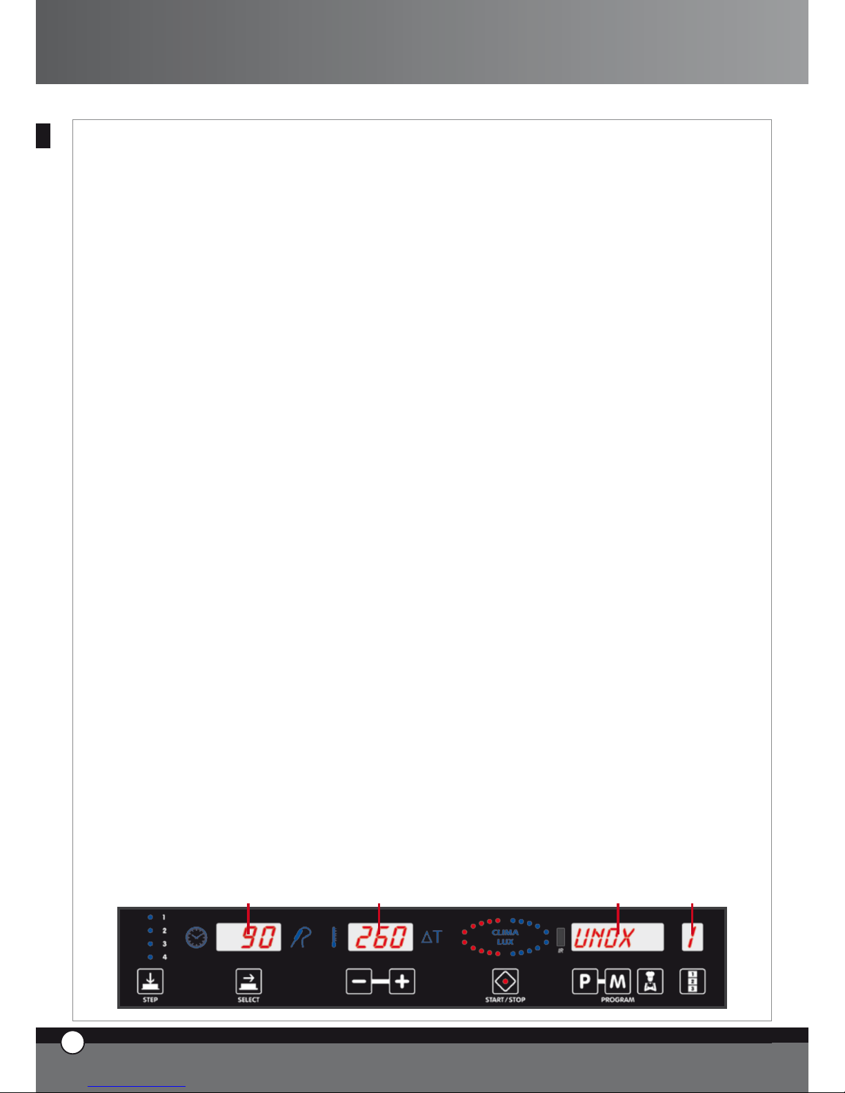
3.2 LAYOUT OF THE CONTROL BOARD
1 2 43
ENGLISH
ENGLISH
4
3
ENGLISH
ChefTop™ - BakerTop™
Page 5
3.3 POWER UP / POWER DOWN
When the power to the oven is supplied, the control
board automatically turns on.
After 15 minutes if any button is not touched and there is
no appliance in use (ovens, blast chillers, holding cabinet)
the control board goes to stand by mode : only the led
“START / STOP” is on.
To return the electronic control to full power again, sim-
ply push the button.
To have the electronic control on stand by, keep the
button pushed for 6 seconds while the control is
on; to return it to full power push the button once
more.
3.4 COOKING CHAMBER LIGHT FUNCTIONING
The lights are normally turned off; every time you touch
one of the buttons they turn on for one minute then, after
one minute, they turn off. To turn them on again, push
any of the electronic control buttons.
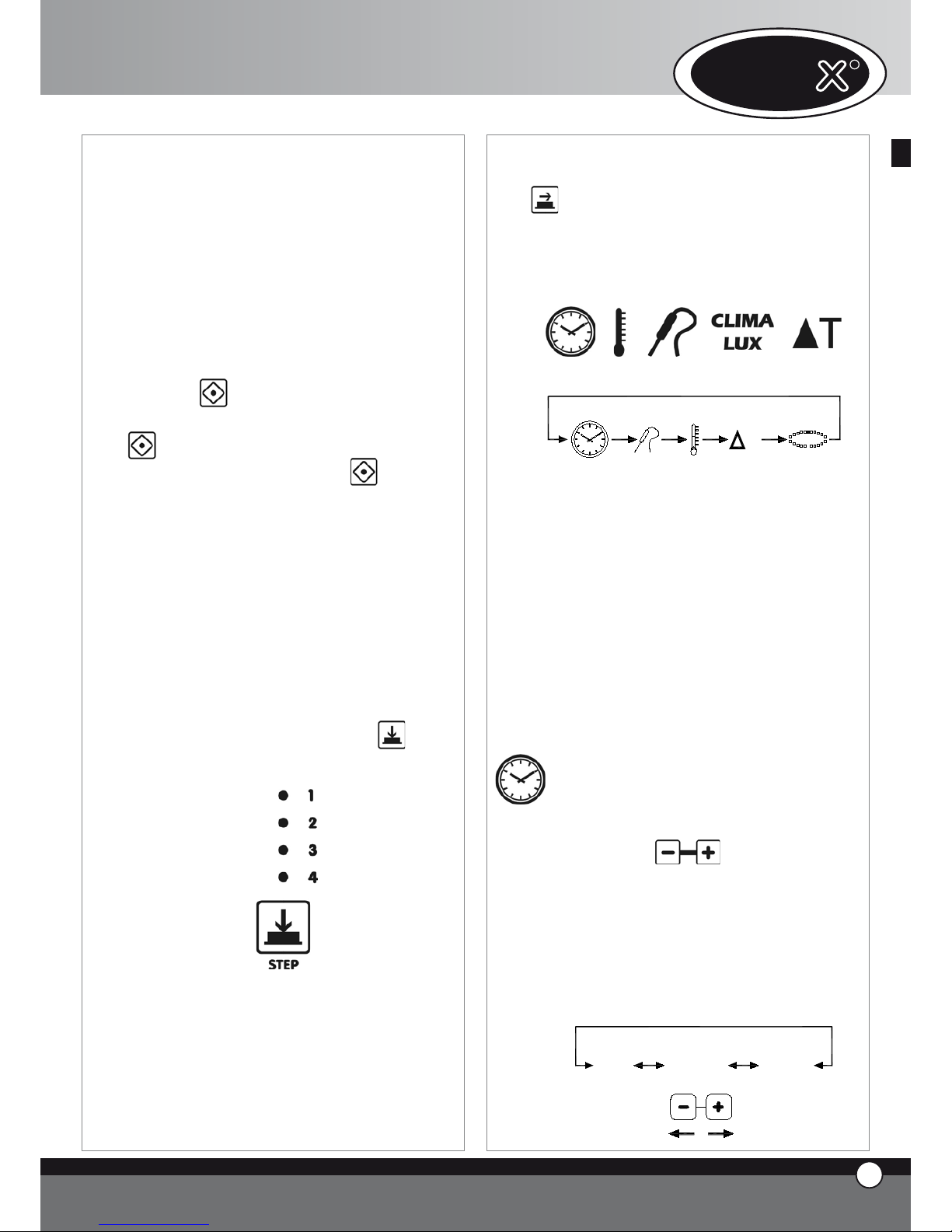
3.5 MANUAL FUNCTIONING
Any cooking program may be composed of 4 steps.
To pass from one step to another touch the button:
the selected step is indicated by the illuminated led.
For each step the user can set the following settings:
time or, as an alternative, core temperature
chamber temperature or, as an alternative, Delta T
(available only if core temperature is set)
climate inside the cooking chamber (STEAM.Maxi™
•
•
•
/ DRY.Maxi™).
To pass from one setting to another press the
button
.
The selected setting is indicated by one of the illuminated
icons:
T
TIM E
CO RE
TE MP ER A TU RE
CA VI TY
TE MP ER A TU RE
DE LT A T
CLIM A
LUX
CL IM A L U X
Time
Core
Temperature
Cavity
Temperature
Delta T CLIMA
LUX
The settings “TIME” and “CORE TEMPERATURE” are
self cancelling: when selecting the “TIME”, the “CORE
TEMPERATURE” setting will be inoperable; vice versa, when selecting the “CORE TEMPERATURE” , the
“TIME” setting will be inoperable.
The “CHAMBER TEMPERATURE” and “Delta T” settings are also self cancelling: when selecting the “CHAMBER
TEMPERATURE”, the “Delta T” setting will be inoperable
; vice versa, when selecting “Delta T”, the “CHAMBER
TEMPERATURE” setting will be inoperable.
It is essential to select either the “TIME” or the “CORE
TEMPERATURE” setting: if none of these selections are
set, the control board does not allow the user to select any
of the following (cavity temperature, Delta T, Climate).
Time setting
The time is shown on the display panel1 and is set
with the buttons
.
When the display panel shows “inF”, the oven will
work continuously until it is manually stopped by
the user. On cooking steps 2, 3 or 4, if the HOLD
“HLD” function is selected, only when the burner is
on. Every time the fans start, the direction of rota-
tion reverses.
S T E P 1
0 h 0 0 ' 9h 5 9'
in F
ENGLISH
UNO
R
4
ENGLISH
Page 6
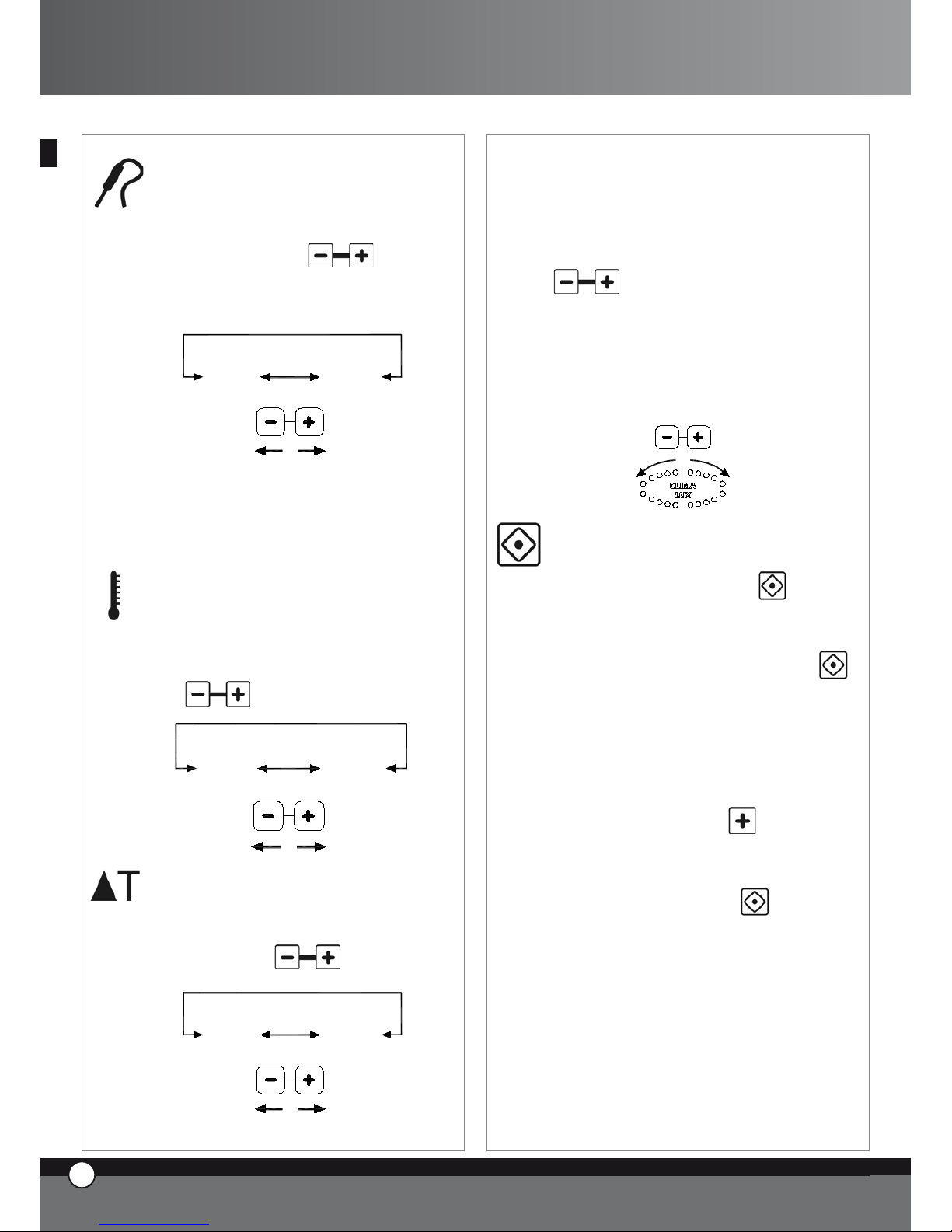
Core temperature setting
The core temperature is shown on display panel 1
and is set with the buttons
.
As soon as the set core temperature is reached, the
co
oking step finishes and the following step (if selected) starts.
0 °C 1 0 0 °C
External core probe kit, XC240, is available to allow
you to connect a further small core probe, suitable
to vacuum cooking and small pieces of food.
Chamber temperature setting
The temperature inside the cooking chamber is
shown on the display panel 2 and is set with the but-
tons
.
2 60 °C0 °C
Delta T setting
Delta T value is shown on the display panel 2 and is
set with the buttons
.
0 °C 1 0 0 °C
CLIMA LUX Climate setting
The setting of the climate inside the cooking cham-
ber (STEAM.Maxi™ / DRY.Maxi™) is shown
by CLIMA LUX ellipse and is set with the buttons
.
The 10 blue led’s indicate the percentage of steam
inside the cooking chamber (STEAM.Maxi™); the
10 red led’s indicate the percentage of dry air
(DRY.Maxi™).
S TE AM
M ax i
D RY
M ax i
Cooking start / stop
To start a cooking cycle touch the
button.
When the cooking starts, the led “START STOP”
turns on.
To stop the cooking cycle touch the button
.
When the cooking cycle has finished, both in ma-
nual and program mode, the oven makes an audible
alarm for 15 seconds and the display 1 flashes for 45
seconds. During this 45 seconds time the “START /
STOP” led remains on:
if you touch the button
you increase the
set cooking time. The oven automatically starts
again (with the last cooking cycle settings)
if you touch the button
the “START /
STOP” led turns off and all settings are reset.
if none of the buttons are touched, after 45 sec-
onds have passed, “START / STOP” led turns off
and all settings are reset
•
•
•
ENGLISH
5
ENGLISH
ChefTop™ - BakerTop™
Page 7
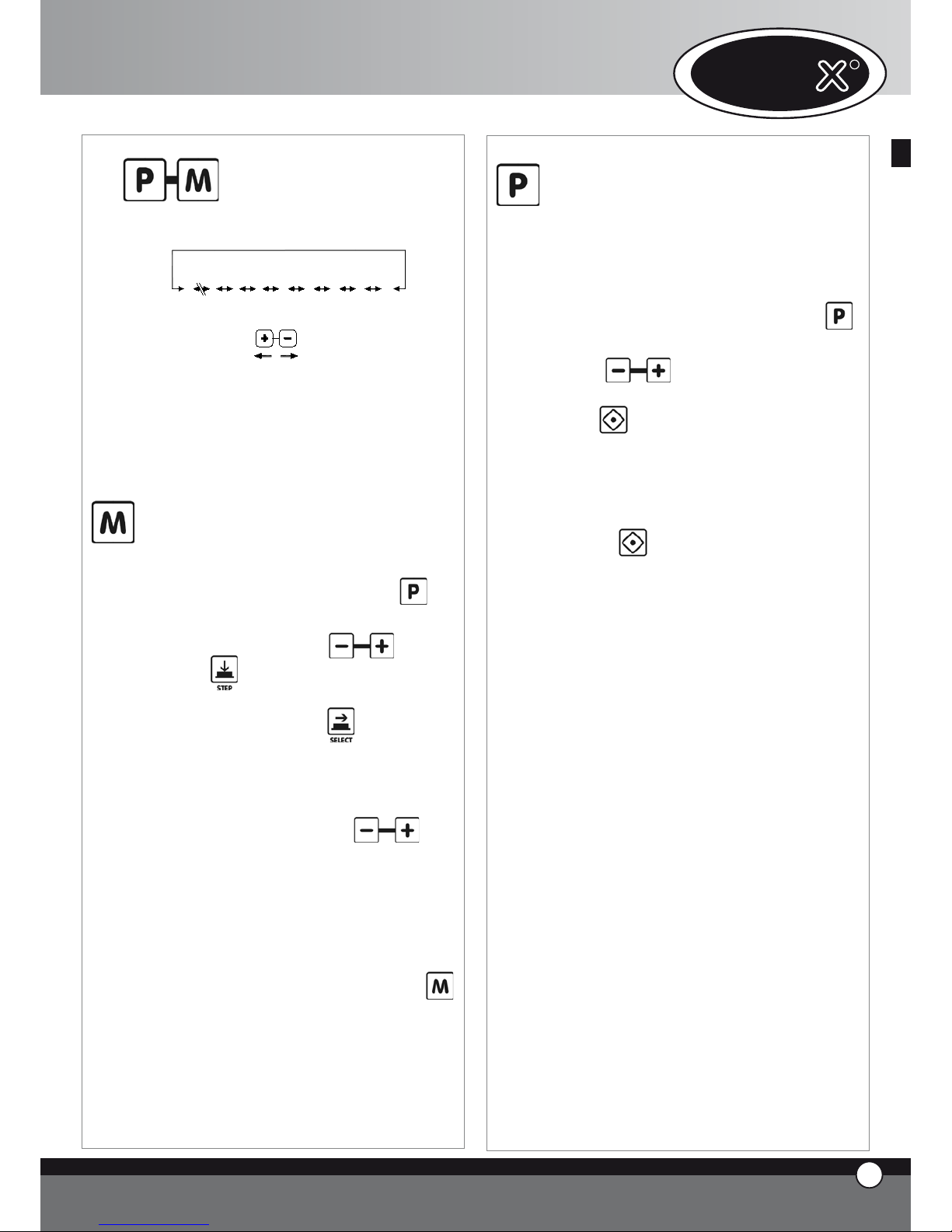
3.6
Working with programs
LP UM P
L3
L2
L1
P0 1
P7 0
P0 2
P0 0
CO O L
The electronic control board allows the user to set,
and select, up to 70 cooking programs.
The electronic control board is already set with the
cooling program (COOL) and the cooking chamber
washing programs (L1, L2, L3, LH2O), for use with
the automatic washing system XC404 if connected.
Program setting - by the user
To set a program proceed as follows:
• the first display shows “Prg”, by pushing but-
ton it is possible to select the type you need to chan-
ge; to change the type push buttons.
• push button and the first display on your
left will show “PRE” message and all the 4 step
leds turns off. By pushing button, you set
the temperature as absolute value or as difference:
the backlighted chamber temperature icon or the
backlighted Delta T icon turns on, and you can set
the required value by pushing
but-
tons.
• select the required cooking settings (time, core
temperature, cavity temperature, Delta T, clima-
te); as for manual working, every cooking pro-
gram can be composed by 1 to 4 steps
• to save the program press and hold the
button for 5 seconds (after 5 seconds have pas-
sed you will hear a bleep) the program is now
saved.
ENGLISH
7
ENGLISH
UNO
R
6
ENGLISH
Use of saved programs, cooling pro
-
gram
To call up a program saved by the user, the cooling
program or a washing program follow the procedure below :
• enter program mode by touching the button
• select the required program by touching the but-
tons
• start the selected program by touching the but-
ton
• when the selected program starts, the led “START
STOP” turns on
• while the cooking program is in operation it is not
possible to modify the program settings.
• it is possible to stop the program by touching the
button
When you start the cooking program, the oven starts
the pre-heating phase: the cooking chamber is heated up to 30°C more than the chamber temperature originally set in the first cooking step. While the
pre-heating phase is on, all the leds and display panels remain turned off apart from: “START / STOP”
led, the display panel 1 which shows the message
“PRE”, and the display panel 3 which shows the selected program. When the required temperature is
reached (step 1 chamber temperature + 30°C) the
oven will make a continuous audible bleep and the
display panels show the settings of the first cooking
step. After you’ve opened the door of the oven,
loaded the food and closed the door, the cooking
program automatically starts.
Once the cooking cycle is finished, both in manual
and programmed mode, if you push “P” button the
5 types display will show “LASTP” message: by pushing “START / STOP” button last cooking cycle
that was used will start again.
Washing programs
The control board is pre-set with 3 washing programs (L1 short, L2 medium, L3 long) + a rinsing
program LH2O + a program for the pre-loading of
the detergent and rinse aid pumps. (LPUMP).
Page 8
Cooking chamber cooling down program
“COOL”
“COOL”, this program is used for cooling down the
cooking chamber, it allows the fans inside the chamber
to rotate whilst the heating elements remain off. The
program works also with the door of the oven open.
While “COOL” program is working, the display shows
cooking chamber temperature.
Important!
It is not possible to remove the fan guard without
the proper removal tool, thanks to the presence of
a fixing screw. If it is necessary to remove the fan
guard for service, do not forget to disconnect the
appliance from the electrical supply.
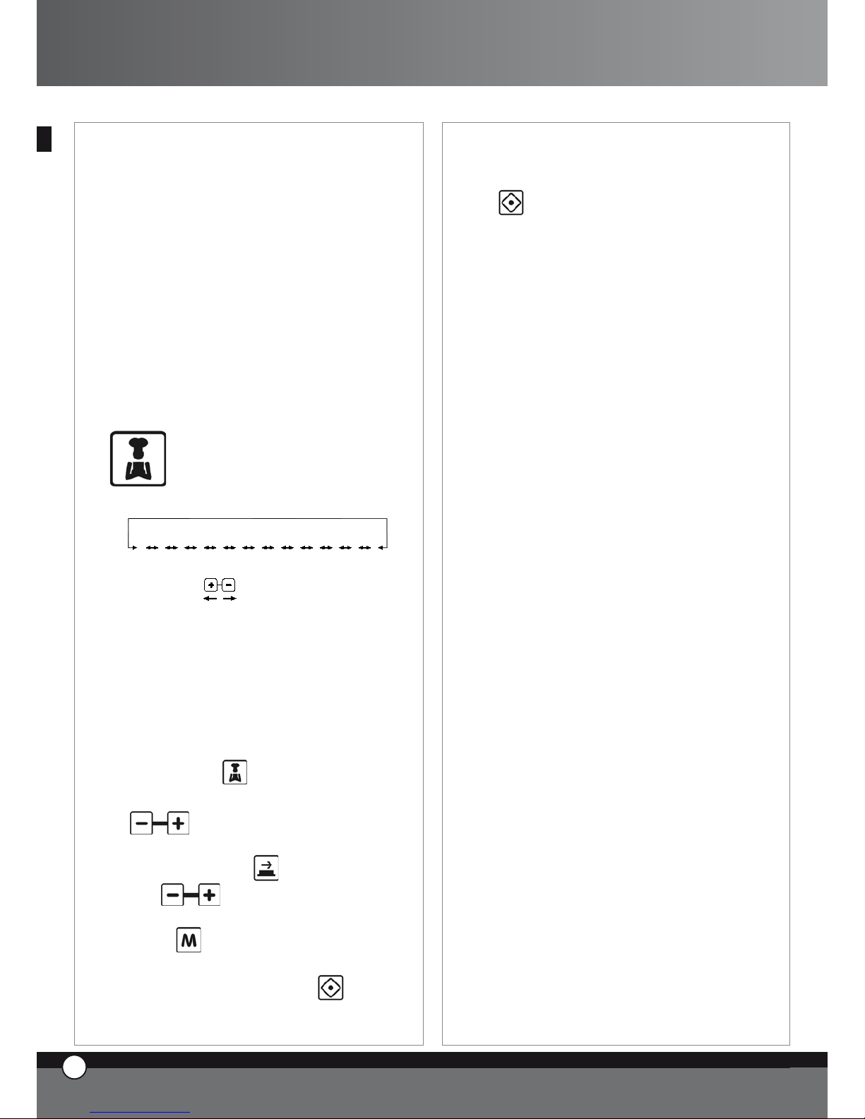
3.7
“ChefUnox™” - “BakerUnox™”
COOKING CYCLES
PIZ ZA
BR EA D
BA KE
PO LL O
FR IE S
ST EA M
ST EA M PR B1
RO AS T
GR IL L
SL OW
VA CU O
RE GE N
PIZ ZA IT AL Y
The electronic control board “ChefTouch™” - “BakerTouch™” is programmed with a series of automatic
cooking cycles pre-set at the UNOX factory: by simply
selecting the required cooking cycle, it is possible to automatically cook an endless range of food.
For every cooking program, you have the possibility to
modify some of the settings in order to personalise the
required cooking results.
To use one of the pre-set programs, proceed as indicated below:
touch the button
select the required program by using the buttons
it is possible to modify the value of the flashing set-
ting by touching the button and, afterwards,
the
buttons (If this new value needs to
be saved in the selected cooking program, touch and
hold the button for 5 seconds until you hear the
confirmation bleep).
start the program by touching the button
when the program starts, the led “START / STOP”
turns on
•
•
•
•
•
while the cooking program is in operation it is not
possible to modify the program settings.
it is possible to stop the program by touching the
button
AUTOMATIC COOKING PROGRAMS FOR DIFFERENT PRODUCTS
“PIZZA ITALY” Cooking program
Progr am for the cooking of “thin” based pizza.
Variable setting: cooking time.
It is recommended to use the UNOX “FAKIRO™” plate
TG860 especially studied for this purpose by Unox.
“PIZZA” Cooking program
Program for the cooking of “thick” based pizza.
Variable setting: cooking time.
“PANE” Cooking program
Program for the cooking of bread and similar products.
The core probe is used to check the cooking level of the product.
Variable setting: core temperature, in order to obtain a variation in the finished product.
“BAKE” Cooking program
Program for the cooking of pastry products.
The core probe is used to check the cooking level of the
product.
Variable setting: core temperature, in order to obtain a variation in the finished product.
“POLLO” Cooking program (only for ChefTop™ series)
Program for the cooking of roast chicken, poultry and
game.
Variable setting: core temperature, in order to obtain a variation in the finished product.
The program is composed by a pre-heating step at 210°C
and in 4 steps with temperature from 180 to 250°C.
It is recommended to use the UNOX “Pollo” grid
GRP810, especially studied for this purpose by UNOX.
“FRIES” Cooking program (only for ChefTop™ series)
Program for the cooking of french fries.
Variable setting: core temperature, in order to obtain a variation in the finished product.
•
•
ENGLISH
8
ENGLISH
7
ENGLISH
ChefTop™ - BakerTop™
Page 9
It is recommended to use the Unox “NoFry” tray
GRP815 especially studied for this purpose by UNOX.
AUTOMATIC COOKING PROGRAMS FOR
DIFFERENT TYPE OF COOKING
“REGEN” Regeneration program (only for ChefTop™ series)
Regeneration program allows the user to regenerate previously cooked and preserved foods.
Variable setting: time of the regeneration process.
“VACUO” Cooking program (available only if the exter-
nal core probe kit XC240 is connected) (only for
ChefTop™ series)
Program for the cooking of vacuumed food.
Variable setting: core temperature in order to adapt the
cooking to different kinds of food.
The use of the very thin core probe XC240 avoids damage to the plastic vacuum bags.
“STEAM” Cooking program (only for ChefTop™ series)
Suitable for meat, fish, vegetables and other products.
Variable setting: core temperature, in order to obtain a variation in the finished product
With this cooking program the fans inside the cooking
chamber turn only clockwise (there is no reversing gear).
(there is no reversing gear).
The amount of water released inside the cooking chamber depends on the set temperature: higher is the temperature, lower is the quantity of water. The oven automatically calculates the right amount of water to release
on the basis of the set temperature.
“STEAM PRB1” Cooking program (available only if the
external core probe kit XC240 is connected) (only
for ChefTop™ series)
The external core probe is required.
Suitable for delicate or small products such as sausages,
fish and steamed vegetables thanks to the use of the external core probe which checks the cooking level.
Variable setting: core temperature, in order to obtain a variation in the finished product
With this cooking program the fans inside the cooking
chamber turns only clockwise (there is no reversing gear).
“SLOW” Cooking program (only for ChefTop™ series)
The core probe is required.
Suitable for slow cooking at low temperatures, ideal for
ENGLISH
UNO
R
8
ENGLISH
large joints of meat.
Variable setting: core temperature, in order to obtain a variation in the finished product from rare to well done, when
the cooking has finished, the product is maintained at a temperature of 70 °C.
“ROAST” Cooking program (only for ChefTop™ series)
The core probe is required.
Suitable for the cooking of roast meat or fish.
Variable setting:. core temperature, in order to obtain a variation in the finished product
It is recommended to use the UNOX “Black” tray
TG835 especially studied for this purpose by UNOX.
“GRILL” Cooking program (only for ChefTop™ series)
Suitable for grilling of meat, fish and vegetables.
Important note: to cook fish it is suggested to use the
ROAST++ cooking program.
Variable setting: core temperature, in order to obtain a variation in the finished product from rare to well done
It is recommended to use the UNOX “FAKIRO™ Grill”
plate TG845 especially studied for this purpose by UNOX.
3.8
MANAGEMENT OF MULTIPLE
APPLIANCES USING THE SAME
CONTROL PANEL
The digital control panel “ChefTouch” - “Baker-
Touch” allows the user to control a variety of UNOX
ChefTop™ - BakerTop™ appliances connected to
the oven. In addition , the introduction of the MASTER
& SLAVE system allows the management , with a single
digital control, multiple ovens. The oven that is used to
control all other appliances, becomes the MASTER oven.
The ovens controlled by the MASTER oven become
SLAVE ovens, and their digital control is inactive. The
MASTER and SLAVE digital control boards are, in case of
emergency, interchangeable.
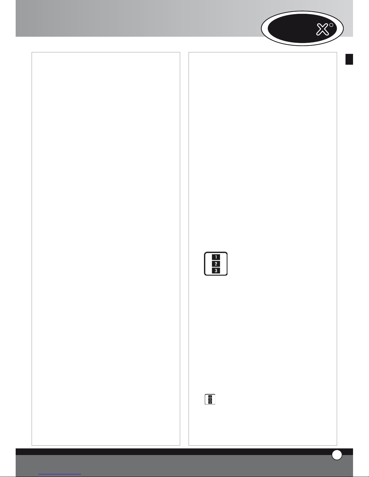
The selection of the appliance to control is made with the
button and the controlled appliance is shown by the
display panel 4.
Number – corrensponding appliance chart
Page 10
Appliance
number
Appliance
code
Device
1 ChefTop™ Oven - master
2 ChefTop™ Oven - slave 2
3 ChefTop™ Oven - slave 3
4 XK304 Blast chiller
5 XL314
Holding cabinet
7 XC 314 Hood
8 XC224 Reverse osmosis system
Appliance
number
Appliance
code
Device
1
BakerTop™ Oven
- master
2
BakerTop™ Oven
- slave 2
3
BakerTop™ Oven
- slave 3
5 XL 404
Prover
7 XC 414 Hood
8 XC224 Reverse osmosis system
When installing UNOX appliances in a column, this kind of
technology allows the user to work in a very ergonomic
way, by using the same working logic.
4. COOKING PRINCIPLES
4.1 Cooking variables
Time
This variable depends a lot on the quantity of food you
put in the oven.
The larger the quantity of food, the longer the cooking
time and vice versa.
A shorter cooking time than that required by the food
results in the food being under cooked. A longer cooking
time than that required by the food causes the burning of
the food surface.
Cavity temperature
The exact setting of the temperature inside the cavity
guarantees a proper cooking of the food, both inside and
outside.
A lower temperature than the proper one dries the
food rather than cooking it.
A higher temperature than the proper one burns the
surface while the core remains uncooked (sometimes
this result is desired, especially with meat).
Hot dry air
Hot dry air system “DRY.Maxi™”, patented by UNOX,
•
•
allows the user to extract the humidity, created by the
product while cooking, from the chamber, thus maintaining a dry environment. In this way the product becomes crispy and crumbly outside (for example: bread,
croissants), while the internal part is dry with an even
structure.
Steam
The introduction of the variable steam (STEAM.Maxi™)
and its different combinations with the temperature allow different types of cooking:
steaming (only steam);
mixed convection-steam cooking (air + steam).
4.2 Chef’s suggestions for even cooking
Preheating
It is always better to pre-heat the oven to a temperature
at least 30-50°C higher than the one required for cooking, in order to reduce the effects of heat loss due to the
opening of the door.
Type of trays and pans
To obtain a perfect cooking quality and an even browning
of the product, it is better not to use high sided containers,
as they do not allow the correct circulation of hot air.
Free space between pans
For even cooking it is important to check that you have
at least 3 cm of free space between the product and the
upper pan.
Quantity of food
To obtain the best results it is important not to overload
the oven, and to check, in the case of bread and pastry,
the orientation of the food on the trays compared with
the air flow.
Core probe positioning
For its correct functioning, it is essential to insert the core
probe, from the top to the bottom, in the thickest part of
the product, until you reach the centre.
In case of foods with reduced thickness, the core probe
should be inserted horizontally to the support surface.
IMPORTANT
Convection ovens need lower cooking temperatures (2040°C less) than those normally used in static ovens.
Pay attention when opening the door!!!
Heat and steam could cause burns.
4.3 Convection cooking
Temperatures from 30°C to 260°C
Convection cooking is done by hot dry air that circulates
around the oven chamber. This allows the heat to be perfectly
distributed, consequently, it is possible to have even cooking.
•
•
ENGLISH
10
ENGLISH
9
ENGLISH
ChefTop™ - BakerTop™
Page 11

The results are perfectly cooked food both on the surface, with a golden crust, and internally.
Suitable for: Cooking au gratin, Roasting and Grilling.
Advantages: Possibility to cook at the same time different
types of food such as vegetables, meat, fish, without the
cross transfer of flavours (as long as the required cooking
temperature is the same for all the cooked dishes).
Foods with free running juices should always be placed at
the bottom of the oven chamber.
4.4 Mixed Steam-Convection Cooking
Temperatures from 30°C to 260°C
Steam from 30% to 90%
The cooking is made by the combination of hot dry air and
steam, evenly distributed inside the chamber. It is surely
the most profitable and efficient of the cooking methods
used today. Cooking times and weight loss are considerably reduced. At the same time, the food remains tender
and flavoursome.
Suitable for: Roasting meats, Braising, Stewing,Cooking
of Fish.
Chef’s suggestions:
For roasting it is better to use a perforated pan or a grid,
this way it will not be necessary to turn the food continually.
By placing a non-perforated pan on the bottom of the oven
chamber,you will be able to collect the meat juices.These
can be used at a later time to make a stock,gravy or sauce.
4.5 Steaming
Temperature from 48°C to 130°C
Steam 100%
The use of ventilated steam is one of the most delicate
ways of cooking food. With this kind of cooking the food
does not lose any liquid; therefore the nutritional contents, the appearance and the weight of the food remain
unaltered.
Suitable for :
Low temperature steaming: Vegetables, Fruit,
Fish,Terrines, Soufflés, Pâtés, Vacuum-Cooking.
Steaming: Vegetables, Fruit, Eggs, Meat,
Fish,Seafood.
Intensive steaming: Potatoes,Root Vegetables
Chef’s Suggestions:
To cook leaf vegetables with steam, it is suggested to initially slightly
moisten the food, in order to avoid the drying out of the leaves.
In addition, to avoid the dispersion of the food, inside the
chamber due to air flow, you can use two baskets (No Fry,
one as a base and another, turned upside down, as a cover).
•
•
•
ENGLISH
11
ENGLISH
UNO
R
10
ENGLISH
4.6 Convection Baking
Temperature from 30°C to 260°C
Convection baking is done by hot dry air that circulates
around the oven chamber. This allows the heat to be perfectly distributed, consequently, it is possible to have even
baking results at all the points of a single pan and on all
the pans. Even baking is also guaranteed when the oven
is fully loaded.
Pastry is perfectly baked both on the surface, with a golden crust, and in the internally, with a uniform structure
and a constant residual humidity.
Suitable for:
Baking of Short Pastry, Puff Pastry, Tart Pastry,
Ccream-puff Pastry
Baking of Sponge cake
Baking of Cookies
Chef’s suggestions:
To obtain the best results in pastry it is necessary to have
a higher distance between the trays, and a higher distance
between the products on the trays.
For products with a light mass ie; meringues it is preferable
to use the air reduction kit, in order to prevent their movement on the trays.
4.7 Convection + Humidity Baking
Temperature from 30°C to 260°C
Humidity from 10% to 20%
The baking is made by hot air with the addition of a variable percentage of humidity, according to the type of food
that has to be baked.
Suitable for:
Baking of leavened dough, such as bread
Baking of sponge cakes, panettone, croissants ,pain
au chocolate.
Chef’s suggestions:
The use of the humidity at the beginning of the baking makes
leavening easier; subsequently, the humidity should be reduced, or even completely eliminated, to obtain the final
crispness and golden surface.
4.8 Convection + Dry Air Baking
“DRY.Maxi™” System (UNOX Worldwide Patent)
Temperatures from 30°C to 260°C
Dry air from 10% to 100%
This is an innovative system that allows the humidity, generated by the product when baking, to be extracted from
the chamber, thus maintaining a dry environment.
The product, thanks to its dry and even internal structure, appears crispy and crumbly.
Suitable for:
Baking of Croissants
Baking of Cookies
Baking of Bread
•
•
•
•
•
•
•
•
Page 12
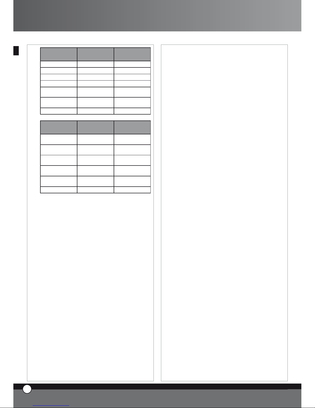
4.9 Cooking with Core Probe + Chamber Temperature
With this kind of cooking, the core temperature and the
chamber temperature have to be set.
The core probe measures the rise of the temperature
inside the product during the cooking process, the end
of the probe has to be inserted in the thickest part of the
food in the centre.With this system, it is no longer necessary to set the time, the oven, will automatically turn off
when the set core temperature is reached, or it will pass
to the following programmed step.
Core Probe cooking is useful to optimise the cooking of
different foods and avoid to continuously checking the
food during its various cooking stages.
Core probe + 100°C ∆T
Sonda al cuore + ∆T a 100°C
Core probe + Cavity temperature
cavity
Set core temperature
C
A
V
I
T
Y
Time in minutes
Temperature
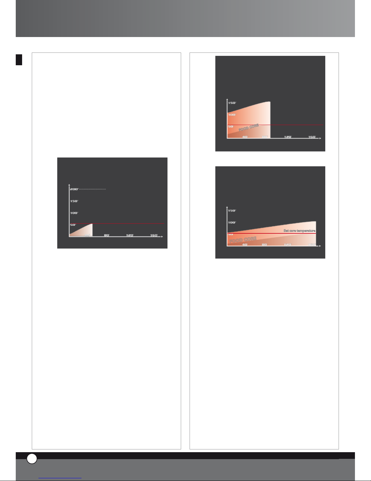
4.10 Cooking with Core Probe + Delta T
In this case you have to set the desired temperature
at the core of the food and the Delta T (difference between the core and the chamber temperature)
CHAMBER TEMPERATURE =
CORE TEMPERATURE + SET DELTA T
In this way the chamber temperature will increase gradually, keeping the difference between the product core
temperature and the chamber temperature you set constant during the cooking cycle. This kind of cooking will
allow you to obtain very soft and delicate cooking, especially useful for large joints of meat.
ENGLISH
11
ENGLISH
Core probe + 100°C ∆T
C
A
V
I
T
Y
Time in minutes
Temperature
Set core temperature
F
O
O
D
C
O
R
E
Core probe + 50°C ∆T
F
O
O
D
C
O
R
E
C
A
V
I
T
Y
Set core temperature
Time in minutes
Temperature
5. CONNECTION WITH THE EXTERNAL
WORLD
The digital control panel of the “ChefTop™” -
“BakerTop™” ovens has been preset to easily connect
the oven to the external world through the present and
future systems of communication: USB, Bluetooth, serial
connections, etc.
The USB interface kit XC226 is available, and allows the
following functions:
Insertion of cooking programs.
Changes in operational parameters (ex: probe setting).
Diagnostics of problems.
Saving of the trends with regard to temperatures
inside the oven chamber or inside the blast chiller
chamber (necessary data for HACCP system)
Connection to a printer (HACCP)
You can find further information included in the kit.
•
•
•
•
•
11
ENGLISH
ChefTop™ - BakerTop™
Page 13
ENGLISH
12
ENGLISH
UNO
R
12
ENGLISH
6. ORDINARY MAINTENANCE
The appliance must be regularly serviced (at least once a
year) by a qualified UNOX service technician.
Any maintenance operations must be carried only by a
qualified UNOX technician.
Before starting any maintenance operation, it is necessary
to disconnect the appliance from the electrical power
supply and allow it to cool down.
The service is needed on:
Combustion
To check if the combustion is correctly made an unburnt
meter (like TESTO 300M or similar) is required. In the
combustion exhaust fumes the percentages of CO in ppm
and of CO2 must be below the maximum values allowed
by the regulations (approx. the CO value must be below
300 ppm).
If the CO value is over le maximum level allowed, proceed with the further check over described here below
to find out the cause of the problem.
Condition of the of the burner flame surface
Remove the burner box from the back of the oven, open it
by removing the upper cover and check the burner surface
is clean and free from any dirt by.
Check the burner surface is not damaged or cracked, otherwise, in case of damage, it is necessary to find out and remove the cause of the problem (too high gas pressure, gas
injector not suitable for the type of gas on use, oven placed
on a non flat surface, water leakage on the burner surface,
etc.) and to have immediately the burner replaced.
Condition of the heat exchanger
Check the heat exchangers are not strained, cracked or
damaged, otherwise it is necessary to remove the cause
of the damage (too high gas pressure, gas injector not
suitable for the type of gas on use, oven placed on a non
flat surface, water leakage on the burner surface, etc.)
and to have immediately the heat exchangers replaced.
Condition of the baffles
Check the baffles are not damaged or cracked by taking
them out from the heat exchangers and check also there
is no soot on them. In case of cracks or soot on the baffles
it is necessary to find out and remove the cause (too high
gas pressure, gas injector not suitable for the type of gas
on use, oven placed on a non flat surface, water leakage
on the burner surface, etc.) and to have immediately the
baffles replaced.
Once the check over and the replacements described
here above have been made repeat the check on the
combustion.
6.1 REPLACEMENT OF THE INTERNAL LAMP
To replace the internal lamp:
disconnect the appliance from the power supply and
allow it cool down.
remove the lateral supports
unscrew the glass cover and replace the lamp with
one with the same characteristics.
Inspect the lamp glass seal and replace if required.
screw the glass cover back in
reassemble the lateral supports
7. SPECIAL MAINTENANCE
All maintenance operations must be only be carried out
by a qualified UNOX technician.
Before starting any maintenance operation it is necessary
to disconnect the appliance from the electrical power
supply and allow it to cool down.
Removal of the back panel will allow access to all internal
components for service and maintenance.
•
•
•
•
•
•
Page 14
ChefTop™
7.1 RESETTING OF THE SAFETY THERMOSTAT
The appliance is supplied with a safety thermostat with a
manual reset. This safety thermostat is needed to protect
the appliance from overheating. When activated, close
gas supply to the burner and the display panel shows the
message “EF4”.
This safety device can be found on the bottom part of the
back panel of the oven: to reset the thermostat,remove
the black cover and push in the small central pin.
If the safety thermostat activates again, contact your nearest UNOX service centre.
7.2 RE-SETTING OF THE LIGHTER DEVICE
In case the burner stops the display 1 shows “GAS”
message, the button flashes and the buzzer bleeps:
it is necessary to push button and wait for the burner
to light again.
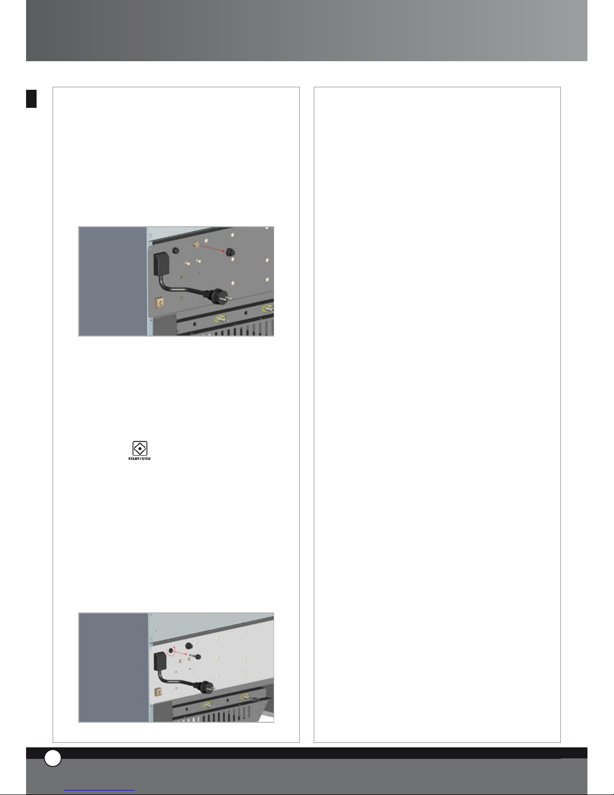
7.3 REPLACEMENTE OF THE FLAME CONTROL FUSE
In case the burner starting system does not work, it is
necessary to check the flame control fuse is not burnt. If
this is the case, the fuse must be replaced.
The flame control fuse is placed on the back of the oven,
below the round black cap indicated by “FUSE” plate.
ENGLISH
11
ENGLISH
WARNING!! Disconnect the oven from the electric
supply before removing the fuse!
To replace the fuse proceed as follows:
• open the round black cap by pushing it and at the same
time turn it counter clockwise of around 20 degrees
• remove the cap of the fuse holder
• remove the fuse from the fuse holder cap
• replace the fuse with a new one with similar technical
characteristics (Fast 1,6A – 250V)
• place the fuse holder cap back
• close the round black cap by pushing it and at the same
time turn it clockwise of around 20 degrees
8. TURNING OFF IN CASE OF
MALFUNCTION
In case of malfunction it is necessary to disconnect the
appliance:
switch off the electrical power supply isolator switch,
that is between the appliance and the network.
close the gas cock
contact your nearest UNOX service centre.
•
•
•
13
ENGLISH
ChefTop™ - BakerTop™
Page 15
ENGLISH
12
ENGLISH
UNO
R
14
ENGLISH
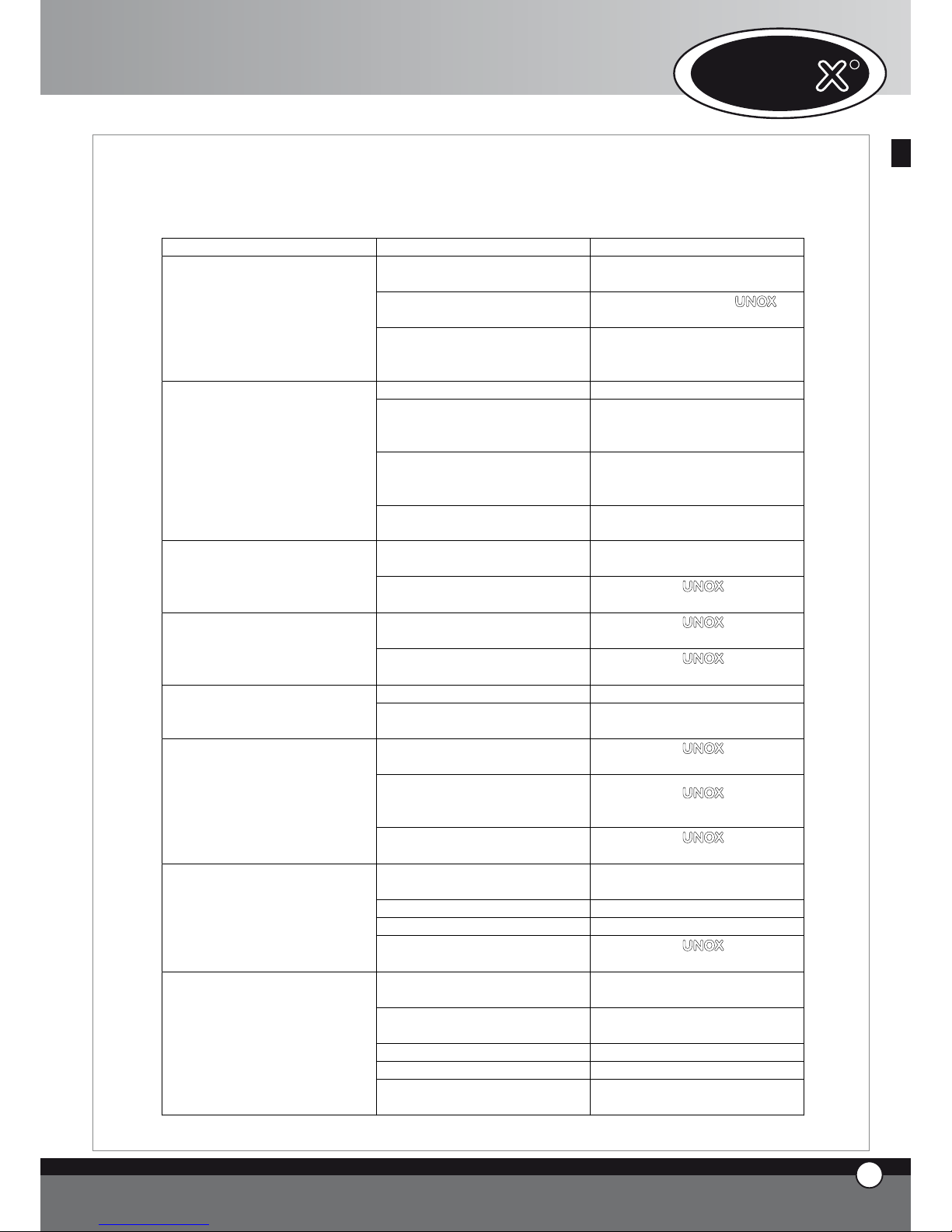
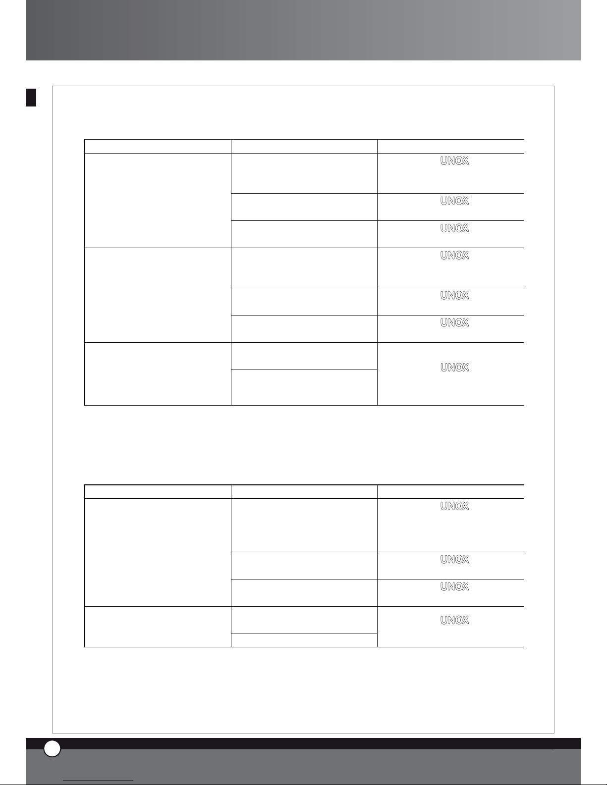
9. MALFUNCTIONS – PROBLEMS CAUSES AND REMEDIES
The guide below will help the user rectify minor faults.
BREAKDOWN CAUSE SOLUTION
The supply mains voltage is
missing
Restore the voltage
Intervention of one of the fuses on
the power board
Apply to a qualified UNOX
technician for service
The oven is completely turned off
The electrical connection to the
mains has not been made in the
correct way
Check the connection of the
appliance to the mains
The water inlet valve is closed Open the water inlet valve
The connection to the water
supply or to the tank has not been
made in the correct way
Check the connection to the
water supply or to the tank
The tank is empty (in case the
appliance is connected to an
external tank)
Pour water in the tank
The humidity control of the oven
is on, but the water does not
come out of the pipes
The filter on the water inlet is
blocked
Clean the filter
The door of the oven is open or
not properly closed
Close the door in the correct way
The oven does not start even
though you have set the time or
the core temperature and pressed
START / STOP button
Damaged door magnetic micro
switch
Apply to a UNOX qualified
technician for service
Damaged door seal
Apply to a UNOX qualified
technician for service
There is water coming out though
the door and the sealing even
though the door is closed
Loose door mechanism
Apply to a UNOX qualified
technician for service
Blown lamp Replace the lamp
The oven light does not turn on
Loose lamp
Place correctly the lamp in the
lamp holder
The fans do not reverse their
rotation
Apply to a UNOX qualified
technician for service
One of the fans is not rotating (in
case of oven with more than one
motor)
Apply to a UNOX qualified
technician for service
The cooking is not even
One of the heating elements is
broken
Apply to a UNOX qualified
technician for service
The fuse of the ligher device is
damaged
Replace the fuse placed on the
back of the oven
No gas supplì Apply to the gas company
Low gas pressure Apply to the gas company
The flame goes out
Defective gas electrovalve
Apply to a UNOX qualified
technician for service
Inverted Phase and Neutral
Togliere la spina e reinserirla
ruotata di 180 gradi
Lighter device fuse is damaged
Replace the fuse placed on the
back of the oven
No gas supply Apply to the gas company
Low gas pressure Apply to the gas company
No flame lighting
Defective gas electrovalve
Apply to a Unox qualified
technician for service
Page 16
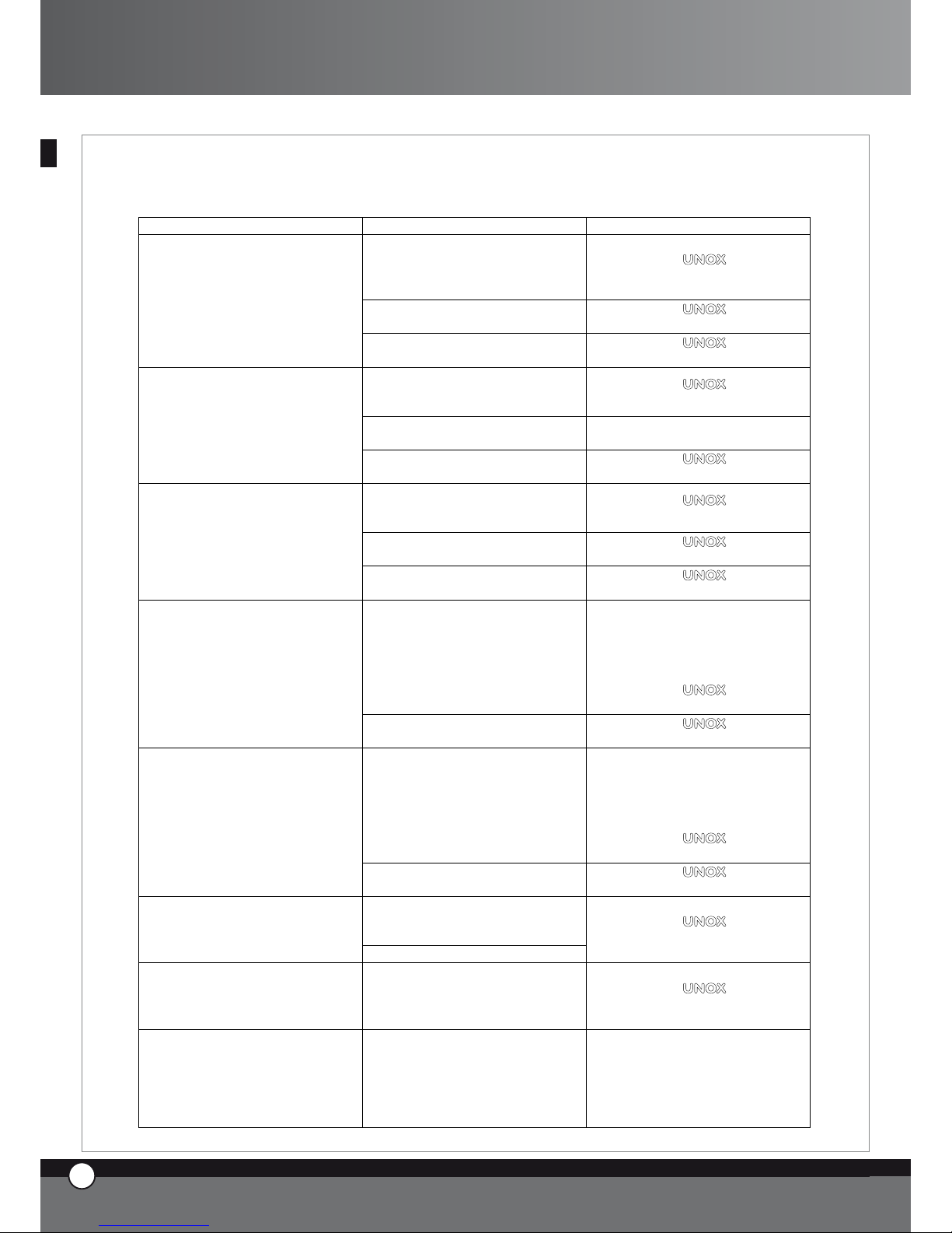
10. ERROR MESSAGES
10.1 OVEN ERROR MESSAGES
BREAKDOWN CAUSE SOLUTION
The connection wires of the
chamber probe 1 are
disconnected from the power
card
Apply to a UNOX qualified
technician for service
Damaged cavity probe 1
Apply to a UNOX qualified
technician for service
The display panel 1 shows
continuously the message EF1
Damaged power card
Apply to a UNOX qualified
technician for service
The connection wires of the cavity
probe 2 are disconnected from
the power board
Apply to a UNOX qualified
technician for service
Damaged cavity probe 2
Apply to a Unox qualified
technician for service
The display panel 1 shows
continuously the message EF2
Damaged power card
Apply to a UNOX qualified
technician for service
The connection wires of the core
probe 2 are disconnected from
the power card
Apply to a UNOX qualified
technician for service
Damaged core probe
Apply to a UNOX qualified
technician for service
The display panel 1 shows
continuously the message EF3
Damaged power card
Apply to a UNOX qualified
technician for service
Intervention of the thermic
protection of one of the motors
Disconnect the oven from power
supply, wait for the appliance to
cool down and restart the oven: if
the display shows again the
message EF4
Apply to a UNOX qualified
technician for service
The display panel 1 shows
continuously the message EF4
Damaged power card
Apply to a UNOX qualified
technician for service
Intervention of the safety thermic
device
Disconnect the oven from power
supply, wait for the appliance to
cool down and restart the oven: if
the display shows again the
message EF5
Apply to a UNOX qualified
technician for service
The display panel 1 shows
continuously the message EF5
Damaged power card
Apply to a UNOX qualified
technician for service
Control board / Power card
connecting cable is damaged or
disconnected
Display no. 1 shows continuously
EF6 message
Oven power card is damaged
Apply to a UNOX qualified
technician for service
Display no. 1 shows continuously
EF7 message
Lost of communication between
the oven and connected
accessories
Apply to a UNOX qualified
technician for service
Display 1 shows “GAS” message,
“START/STOP” led flashes and
the buzzer bleeps
The burner does not ignite
Push “START/STOP” button and
wait for the burner to ignite again.
If after several tries, the burner is
still not igniting, invert the phase
and the neutral by turning the plug
of 180 degrees.
ENGLISH
11
ENGLISH
15
ENGLISH
ChefTop™ - BakerTop™
Page 17
ENGLISH
12
ENGLISH
10.2 BLAST CHILLER ERROR MESSAGES
BREAKDOWN CAUSE SOLUTION
The connection wires of the cavity
probe are disconnected from the
power card
Apply to a UNOX qualified
technician for service
Damaged chamber probe
Apply to a UNOX qualified
technician for service
The display panel 1 shows the
message EA1
Damaged blast chiller power card
Apply to a UNOX qualified
technician for service
The connection wires of the core
probe are disconnected from the
power card
Apply to a UNOX qualified
technician for service
Damaged core probe
Apply to a UNOX qualified
technician for service
The display panel 1 shows the
message EA2
Damaged blast chiller power card
Apply to a UNOX qualified
technician for service
Overpressure in the refrigeration
circuit
Disconnect the blast chiller from
the power supply, wait for about
20 minutes, and connect again the
appliance: if the display shows
again the message EA3
Apply to a UNOX qualified
technician for service
The display panel 1 shows the
message EA3
Damaged blast chiller power card
Apply to a UNOX qualified
technician for service
Display no. 1 shows continuously
EA4 message
Filters working limit reached Take out the filter and wash it
Oven / blast chiller connecting
cable is damaged or disconnected
Display no. 1 shows continuously
EA5 message
Blast chiller power card is
damaged
Apply to a UNOX qualified
technician for service
UNO
R
16
ENGLISH
Page 18
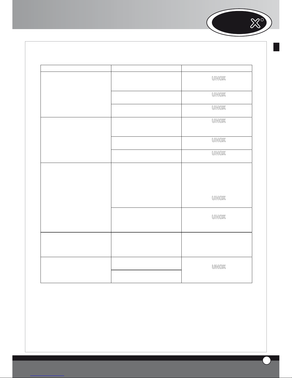
10.3 HOLDING CABINET ERROR MESSAGES
BREAKDOWN CAUSE SOLUTION
The connection wires of the
chamber probe are disconnected
from the power card
Apply to a UNOX qualified
technician for service
Damaged chamber probe
Apply to a UNOX qualified
technician for service
The display panel 1 shows
continuously the message EL1
Damaged holding cabinet power
card
Apply to a UNOX qualified
technician for service
The connection wires of the
humidity probe are disconnected
from the power card
Apply to a UNOX qualified
technician for service
Damaged humidity probe
Apply to a UNOX qualified
technician for service
The display panel 1 shows
continuously the message EL2
Damaged holding cabinet power
card
Apply to a UNOX qualified
technician for service
Oven / holding cabinet connecting
cable is damaged or disconnected
Display no. 1 shows continuously
EL3 message
Holding cabinet power card is
damaged
Apply to a UNOX qualified
technician for service
10.4 HOOD ERROR MESSAGES
BREAKDOWN CAUSE SOLUTION
The connection wires of the
temperature probe are
disconnected from the power
card
Apply to a UNOX qualified
technician for service
Damaged temperature probe
Apply to a UNOX qualified
technician for service
The display panel 1 shows
continuously the message EC1
Damaged hood power card
Apply to a UNOX qualified
technician for service
Oven / hood connecting cable is
damaged or disconnected
Display no. 1 shows continuously
EC2 message
Hood power card is damaged
Apply to a UNOX qualified
technician for service
ENGLISH
11
ENGLISH
17
ENGLISH
ChefTop™ - BakerTop™
Page 19

ENGLISH
12
ENGLISH
10.5 OSMOSIS SYSTEM ERROR MESSAGES
BREAKDOWN CAUSE SOLUTION
Pressure transducer is damaged
Transducer / power card
connecting cable is damaged or
disconnected
Display no. 1 shows continuously
EO1 message
Osmosis power card is damaged
Apply to a UNOX qualified
technician for service
Liter-counter is damaged
Liter-counter / power card
connecting cable is damaged or
disconnected
Display no. 1 shows continuously
EO2 message
Osmosis power card is damaged
Apply to a UNOX qualified
technician for service
Display no. 1 shows continuously
EO3 message
Filters working limit reached
Apply to a UNOX qualified
technician for service
Display no. 1 shows continuously
EO4 message
Inlet water pressure is too low
Verificare che arrivi acqua
all’ingresso dell’osmosi
Oven / osmosis connecting cable
is damaged or disconnected
Display no. 1 shows continuously
EO5 message
Osmosis power card is damaged
Apply to a UNOX qualified
technician for service
UNO
R
18
ENGLISH
Page 20
B. INSTRUCTION FOR THE IN-
STALLER
1. WARNING
All the operations of installation, assembly, service and
assistance must be carried out by qualified personnel according to current laws and regulations.
Please read carefully the instruction manual before the
installation and commissioning of the appliance.
The appliance must be unaltered (check for any transport damage). Remove all informative material from the
chamber.
Avoid to modify the components sealed by the producer
with the intention of improving the performances of the
equipment; the producer refuses all responsibility for any
damage to persons or things that may be caused by an
improper use of the appliance and the warranty is automatically invalidated.
The settings, the gas supply pressure values and the
technical data are indicated on CHART A of every oven
model.
2. PRELIMINARY OPERATIONS
2.1 INSTALLATION SITE
Before placing the appliance, please verify the overall dimensions and the exact position of the electrical and water connections and of the fumes exhaust as indicated on
the attached file “Technical Data”.
In particolar, check the earthing and the exhaust fumes
scavenging are in compliance with the safety.
Avoid to install the oven on places where there is a risk
of explosion.
Avoid to install the oven outdoor without a proper and
complete rain proof protection.
Avoid to install and use the oven inside small rooms where
there is insufficient air change.
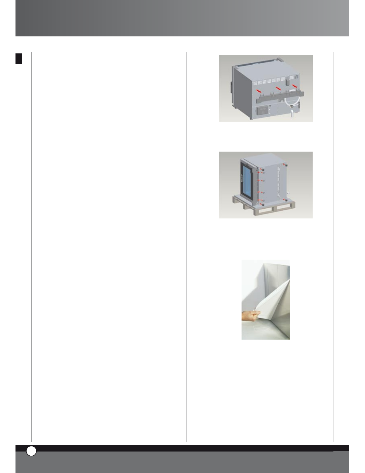
2.2 PRESETTING FOR POSITIONING
You will find the feet inside the appliance.They must be
fitted to the oven.
Never use the appliance without its feet.
Remove the drip tray from the back of the oven by using
a screwdriver.
Place the oven on one side.
Insert the feet in the indicated positions and the tray
guides as shown in the picture.
2.3 REMOVAL OF THE PROTECTIVE FILM
Carefully remove all the protective film from the external
walls of the appliance.
Pay attention not to leave any residue of glue.If there
should be any residue of glue please remove it with an
appropriate solvent.
Remove the probe protection.
13
ENGLISH
19
ENGLISH
ChefTop™ - BakerTop™
Page 21
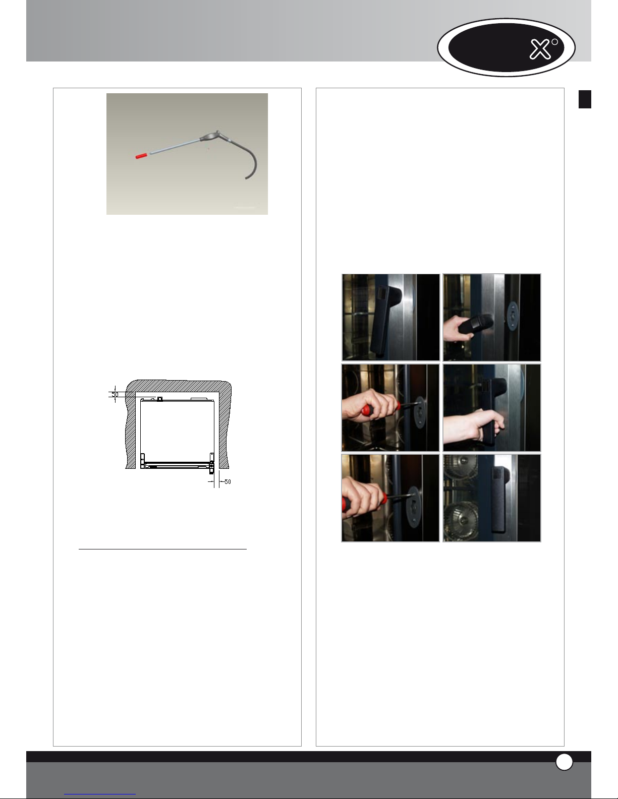
2.4 POSITIONING
Place the appliance respecting the safety standards indicated below.
Place the appliance so that its back can be easily reached
in order to make the electrical connections and to provide the necessary service.
Avoid to install the oven near heat sources.
The appliance is not suitable for built-in installation
or side by side positioning.
It is recommended to leave 10 cm cm of free room all
around the appliance.
With particular reference to the ovens, all models must
be placed upon a support, such as a prover, a stand or a table.
Never install the appliance on the floor.
If the appliance is placed near walls, partitions, kitchen
cabinets, decorated edges, etc., it is recommended these
are made of non combustible material.
Otherwise, they must be coated with non combustible
thermal insulating material and the fire prevention standards must be respected.
Do not install the appliance near a fryer. because some fat
may enter inside the oven and settle on the electric parts,
causing malfuncitoning of the equipment, or enter inside
the burner box and cause problems on the gas combustoin.
Avoid to install the appliance near inflammable substances
containers, eg.: gas cylinders.
Verify that the appliance is installed on a flat and
level surface.
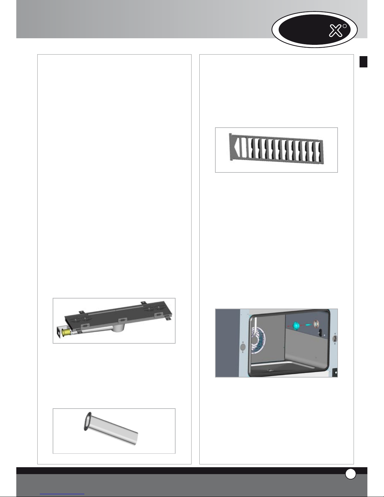
In case, once the oven is placed, the door handle does not
properly close the door, it is necessary to accommodate
the handle latch, as described here below:
• open the door of the oven (pic.1), slightly unloose the
fixing screws of the door latch (pic.2)
• close the door and turn the handle to lock it (pic.3)
• if the door remained closed and the handle is perfectly
in vertical position, open the door and tightly fix the fixing
screws of the latch (pic.4).
• in case the problem is not solved, repeat the procedure
unloosing more the latch fixing screws.
WARNING! In case the oven is placed on a non perfectly flat surface, the handle does not properly close: if
the surface is only lightly deformed, it is possible to solve
the problem by following the latch accomodation procedure described here above; this procedure can not be
used to solve the problem in case the surface shows big
deformations.
Install the appliance inside rooms where there is a sufficient air
change in order to avoid the formation of toxic substances.
Attention! Keep free the exhaust fumes chimney
placed on the top of the oven.
For the installation, the exhaust fumes conveying and the
minimum wall ventilation, refer to installation and safety national standards in force in the country where the oven is
14
ENGLISH
UNO
R
20
ENGLISH
Page 22
installed. Make sure the air volume needed for combustion
is not blocked by objects placed under or around the oven,
especially near holes or slots.
A correct air change grants a proper combustion of the oven
burner and a healthy room for the users.
On the basis of to the scavenging system used, the gas oven
models are classifiable as follows:
Type A1 (ovens with thermic power < 14kW): exhaust
gasses are scavenged in the room where the oven is installed.
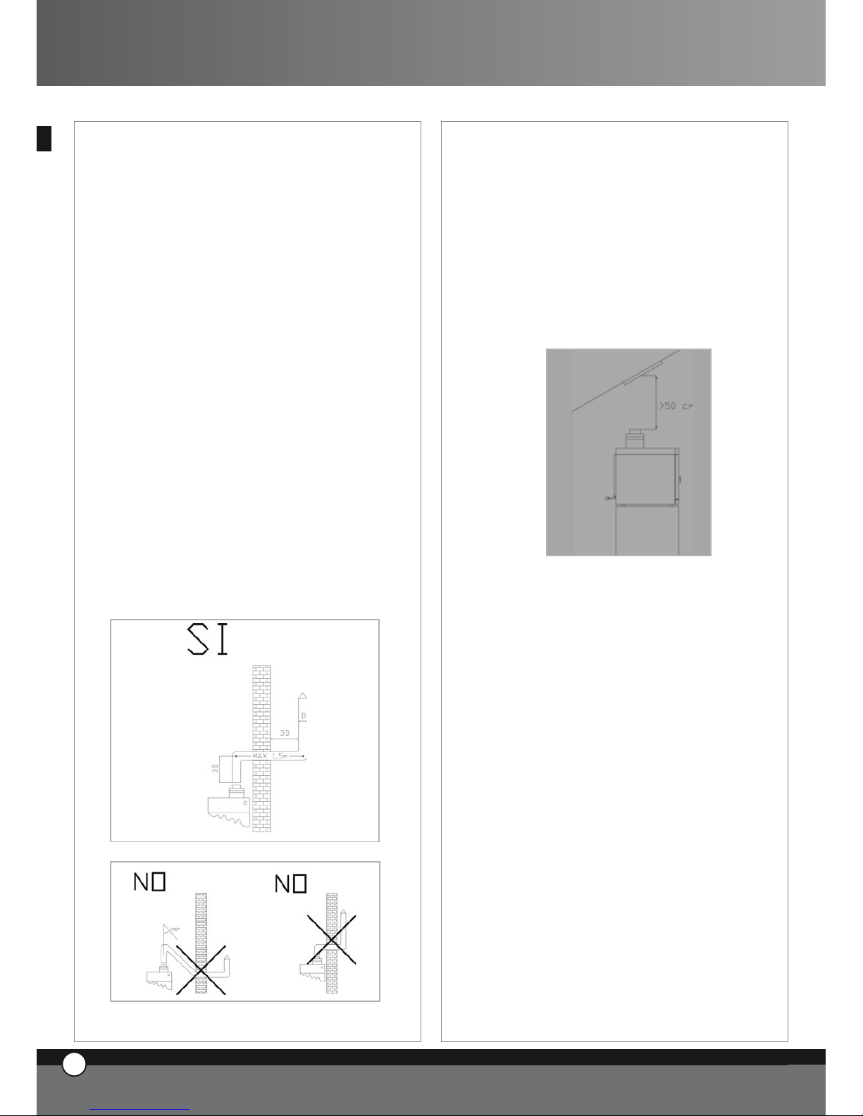
Type B11 (ovens with thermic power < 14kW): Exhaust
fumes are scavenged to the outside through a natural draught
chimney. In this type of installation, make sure that, for all its
length, the section of the chimney is larger than the section of
the oven exhaust pipe. Above the draught breaker there must
be a vertical length longer at least three times the diameter of
the pipe. The exhaust system must have for all its length an ascending path with a minimum slope of 10%. Moreover, there
mustn’t be any angle smaller than 90”. Avoid the horizontal
part of the connection exceed the approximate length of 1,5
meters. In case the connection is not possible, install a hood at
least at 50 cm from the oven draught breaker.
Attention! Placing a hood too near the draught breaker may
cause an over depression on the draught breaker that would,
then, attract a greater gas quantity inside the burner with consequent blasts and leave harmful unburnt gasses.
It is recommended to install a chimney cover on the external
top part of the flue in order to avoid the rain to get inside the
oven and to limit the Venturi effect depressions that may occur
in case the chimney is exposed to strong external draughts.
Type B21 (ovens with thermic power > 14kW): Exhaust
fumes are scavenged to the outside through the hood. The
hood must be at, at least, 50 centimetres from the draught
breaker: if the hood is placed to close to the draught breaker
it may cause an over depression on the draught breaker that
would, then, attract a greater gas quantity inside the burner
with consequent blasts and leave harmful unburnt gasses.
It is recommended to install a chimney cover on the external
top part of the flue in order to avoid the rain to get inside the
oven and to limit the Venturi effect depressions that may occur
in case the chimney is exposed to strong external draughts.
The choice about the type of gasses scavenging must be made
accordingly to local laws on gas appliances installation.
All UNOX gas ovens are supplied with an anti-wind chimney,
incorporated to the gasses scavenging system, to avoid obstructions and not proper draught: it has never to be removed
because it is integral part of the oven.
3. ELECTRICAL CONNECTION
3.1 WARNING
The connection to the electrical power supply system
must be carried out according to the current local regulations.
Before connecting the appliance, make sure that the voltage and the frequency correspond to those stated on the
data plate of the appliance.
The appliance must be placed in such a way that the connecting plug to the network can be easily reached.
Place an omni-polar switch between the appliance and
the network in such a way that it will be easily accessible after the installation. The contacts of this switch must
have a minimum opening distance of 3 mm and the switch
must have an appropriate input (for example: thermalmagnetic switch).
21
ENGLISH
ChefTop™ - BakerTop™
Page 23
UNO
R
22
ENGLISH
The use of a safety switch for fault current is suggested.
When the appliance is working, the power supply voltage
must not diverge from the value of the nominal voltage,
indicated on the data plate, by more than ± 10%.
3.2 CONNECTION TO THE ELECTRICAL SUPPLY
MAINS
UNOX gas ovens are equipped with electrical cable and
Schuko plug (monophase 230V) that has to be simply
plugged in a proper outlet (check the outlet is suitable to
the supplied Schuko plug).
Pay attention on plugging in the equipment: in case the
oven locks at any time the flame lighting starts try to turn
the plug of 180 degrees (on board safety system that
avoid Phase-Neutral polarity inversion).
The electric supply outlet must be clean, in good
conditions and far from fats, oils and other substances that may compromise the electric connection.
3.3 EQUIPOTENTIAL SYSTEM
The appliance must be included in an equipotential system
whose efficiency must be properly checked according to
the current laws. This connection must be done between
different appliances through the terminal marked with
the symbol: simbolo morsetto equipotenziale
The equipotential conductor must have a minimum section of 10 mm2.
4. GAS C0NNECTION
4.1 WARNING
Before proceeding with the gas connection, the qualified
installer must check the data indicated on the technical
data plate match with the available gas type.
The equipment is set and tested in production for LPG
gas, G30 type (butane/propane G30/G31) at a nominal
pressure value of 28-30/37 mbar.
In case the gas available to be connected to the equipment is different from the gas the oven is set to, see paragraph 4.3.
4.2 CONNECTIONS
The equipment has to be connected to the gas accordingly to the standard in force.
Install an interception gas cock between the equipment
and the gas supply in an accessible position.
The connection to the gas main, through the ¾” ISO 71 type fitting placed on the back left panel of the oven,
can be made by using flexible or not flexible pipes and by
placing an approved interceptiongas cock between the
equipment and the gas supply.
In case flexible pipes are used, make sure they are made
in stainless steel, not placed close to external heat sources
(e.g.: fryers, open burners etc.) and not subject to twisting and/or traction.
In case non metallic material are used, e.g.: sealing, they
must be certified and complying with the European standards in force.
Check the gas circuit seal by putting on the fittings a suds
solution or non corrosive specific foaming products.
Important: never use a flame to check possible gas leaks.
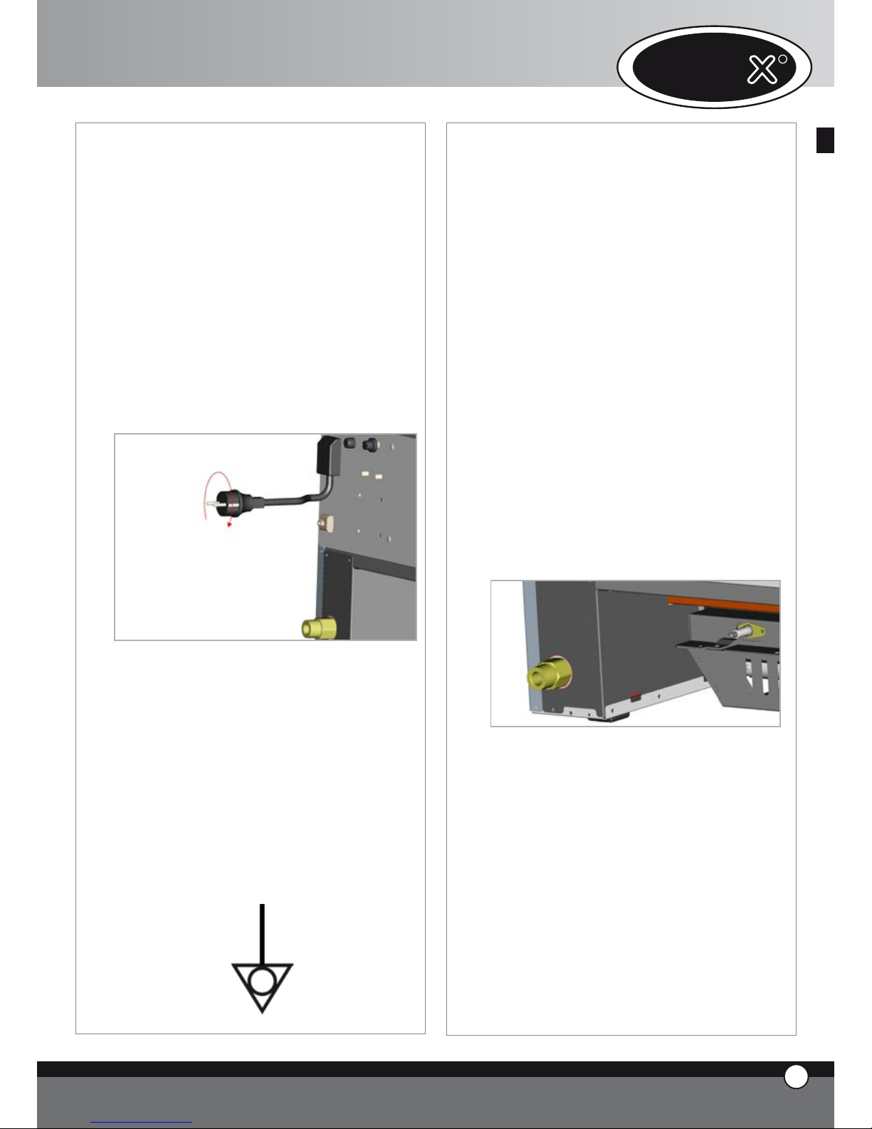
4.3 SET AND ADJUSTMENT TO DIFFERENT GAS TYPES
Before carrying out work on the appliance, close the gas
cock and disconnect the electrical supply.
The accommodation has to be made by qualified person-
Page 24
ChefTop™
nel. Referring to the attached technical data sheet, replace
the main nozzle and adjust the primary air by setting the
referred bush.
Check the diameter of the nozzle, printed on the nozzle,
that has to be replaced is 1/100 mm.
The nozzle is placed on the lower left back side of the
equipment. To replace the nozzle and adjust the primary
air setting, proceed as follows (see the picture here below):
• loose screw A
• move the bush B as indicated on the attached chart
• unfix and take off the nozzle C by using a 13 mm spanner
• install the nozzle suitable to the gas type available on
the main (see proper technical data sheet)
• place the bush B at the right distance H (see proper
technical data sheet).
• screw the screw A
Warning!
After the equipment has been set to a different
type of gas:
• place on the equipment place a inerasable sticker with
the new setting data.
• Seal again the adjusted parts.
• Proceed with gas circuit seal test procedure.
• Make a general working test on the whole system.
4.4 CHECK OF THE NOMINAL THERMAL POWER
RATE
The nominal thermal power rate has to be checked by
authorized personnel or by the company in charge on the
basis of the information indicated on this manual.
This check is required at any new installation, transformation or adjustment to different gas types and after any
maintenance work.
The nominal thermal power rate and the connection pressure values are indicated on the technical data sheet.
Do not remove the parts sealed with red paint.
The required nominal thermal power rate is set by using
the nozzles as indicated on the respective chart of the
technical data sheet and by setting the specific connection
pressure value indicated per gas type.
In case you need a further test to be made on the nominal
thermal power rate, proceed with the volumetric method by using a counter and a chronometer.
The exact volume that has to pass per time unit is indicated on the respective chart on the technical data sheet.
This value for the connection has to be respected with
a tolerance of ±5%. In case a difference value is found,
check the diameter of the used nozzles and inlet pressure
are correctly set.
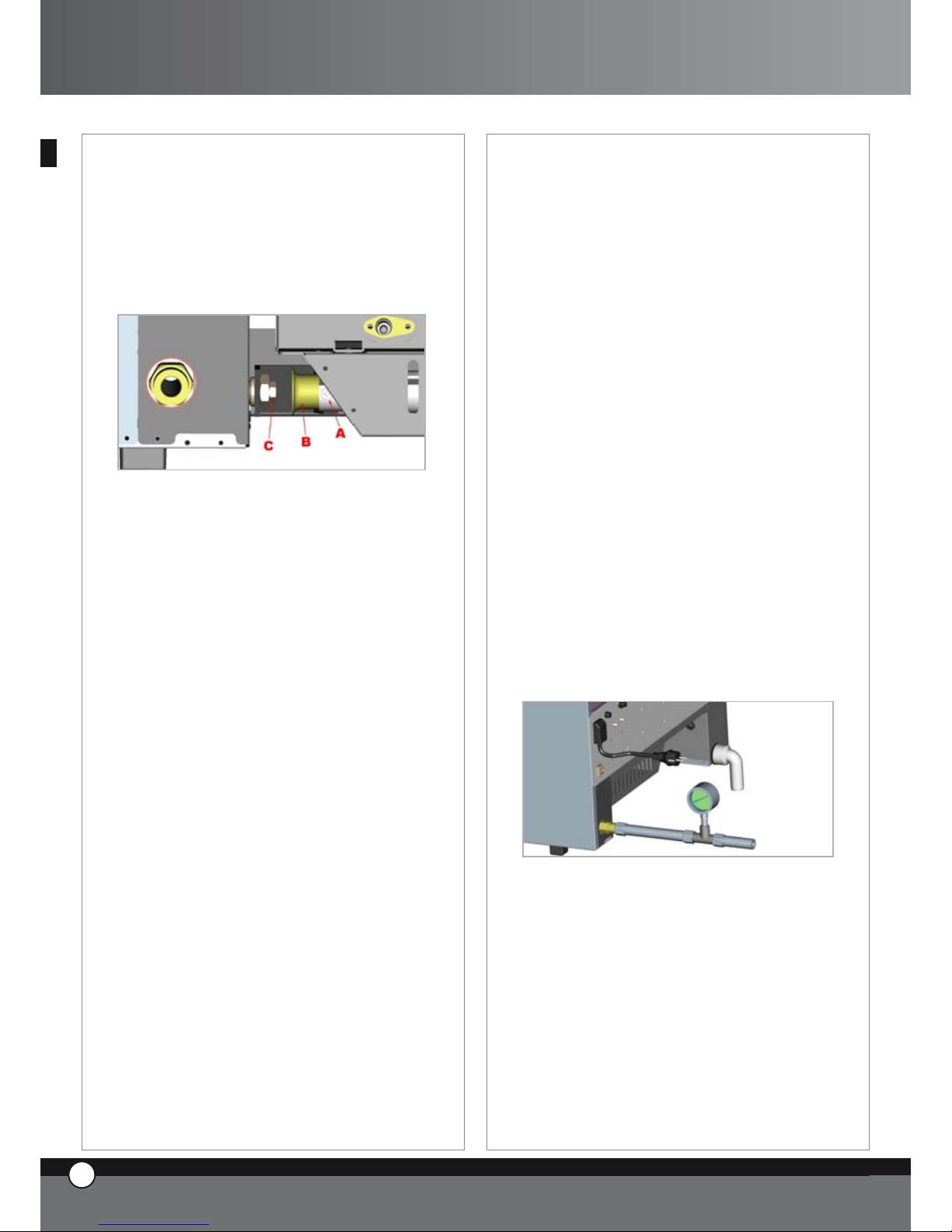
4.5 CHECK OF THE SERVICE PIPE PRESSURE
The service pipe pressure is measured, with the equipment turned on, by using a pressure gauge for fluids (e.g.:
a “U” type manometer with resolution 0,1 mbar or an
electronic manometer): make sure the taken pressure
value matches with the value indicated on the respective
chart.
To check the inlet pressure proceed as follows: close the
gas cock installed between the equipment and the gas
main, remove the gas feeding pipe and insert between
the pipe and the oven gas inlet a T fitting; connect on the
free end of the T fitting a manometer suitable to check
the pressure.
In case the taken pressure value is lower than the value
indicated on the ” CHART A”,(more than 0,2 mbar below
indicated value), apply to local gas company.
Warning!
Never tamper the gas solenoid valve parts set and sealed
by the producer.
23
ENGLISH
ChefTop™ - BakerTop™
Page 25

UNO
R
24
ENGLISH
4.6 CHECK OF CORRECT FUNCTIONING
Turn on the equipment following the instructions indicated here below.
Check the equipment gas circuit is correctly seal and
there are no gas leaks, as indicated on paragraph 4.2
Check the burner flames are evenly lighted by looking
through the burner aeration slots; in details, the flames
have to be blazing and blue without yellows ends.
4.7 SUGGESTIONS FOR THE USER
The technician responsible for the installation has to inform the user about the safety on the use of the equipment, with reference to the information contained in this
manual that has to be delivered together with the equipment. Any special maintenance work (replacement of a
damaged component, adjustment to a different type of
gas, etc.) has to be made by authorized and qualified personnel; after any maintenance work a general check of
the equipment functioning is required.
It is suggested to draw up a service contract in order to
have the equipment checked and tested at least twice a
year, in particular on electric, water and gas connections.
The user is in charge only of the use and daily cleaning of
the equipment.
4.8 TEST OF THE FIRST USE
Turn on the equipment following the instructions indicated here below.
Pay attention while turning on the oven for the first time
because, due to some air bubbles inside the gas circuit,
it may lock; the oven lock is indicated buy the START/
STOP button flashing and intermittent buzzer sound:
keep START/STOP button pushed until the oven starts
again. Repeat this procedure until the air inside gas circuit
is completely bleeded.
In case despite several turning on tries the flame (after
the sparking) keeps on turning off and making the oven
lock, invert the phase with the neutral of the plug (plug
out, turn the plug of 180 degrees and plug in).
Once the oven has been turned on, check the flames
through the aeration slots placed on the back of the
oven.
The technician informs the user about the functioning and
the turning on of the equipment referring to the instructions contained on this manual.
5. WATER CONNECTION
5.1 WARNING
It is necessary to place a mechanical filter and a shut-off
valve between the water system and the appliance.
As required by current laws, the appliance is equipped
with 2 metres of pipe, the respective pipe fitting (3/4”)
with non-return valve and mechanical filter.
Before connecting the water pipe to the appliance please
let some water flow to clear the pipe of any obstructions.
The water used in the appliance must have a pressure
value between 1 and 3 bar and a maximum temperature
of 30°C.
5.2 TREATMENT OF WATER
The water must have a maximum hardness of 5 °FH (this
avoids formation of limestone inside the chamber of the
oven).
It is strongly recommended to use a demineralising appliance (reverse osmosis unit) in order to avoid limestone
and/or other minerals depositing inside the oven.
The UNOX reverse osmosis system, code XC224 is available for this purpose. This system is directly controlled
by the control board of the oven through a self•diagnosis
system.
6. DRAIN CONNECTION
6.1 WARNING
The water coming our from the waste outlet pipe can be
very hot (90°C).
Proper pipes for high temperature must be used for this
connection.
Page 26

ChefTop™
6.2 WATER DRAIN
You find the waste outlet pipe on the rear of the oven. It
has to be connected to an open tundish drain in compliance with current regulations through a rigid or flexible
heat resistant pipe; the diameter of the pipe cannot be
smaller than diameter of the drain connection. The length
of the pipe cannot be longer than one metre.
Avoid reductions in diameter and tight bends along the
whole length of the waste pipe run.
The waste pipe must remain at least 20 cm below the
drain connection to allow the liquids to drain.
6.3 COOKING CHAMBER EXHAUST
The exhaust outlet of the cooking chamber is positioned
on the rear of the oven, at the top.
Do not stack any object and or material on the outlet as
this could cause a blockage of the fumes. Please ensure
that the exhaust outlet is correctly vented and the vicinity
of the outlet is clear of objects and materials that may be
damaged by the fumes.
It is suggested to place the oven below an extraction
hood or to install the UNOX aspiration hood, code
XC314 for ChefTop™- XC414 for BakerTop™, or the
UNOX steam condenser, code XC114. In all installations
please extract the fumes through the UNOX tube, code
TB1520A0, avoiding tight bends in the pipework run.
7. ACCESSORIES CONNECTIONS (PROVER, HOOD, BLAST CHILLER, ETC.)
The digital board of the oven controls all the accessories
(hood, holding cabinet, blast chiller, reverse osmosis system).
The accessories controlled by the oven are connected
through RJ45 connectors that are positioned on the rear
of the oven.
To connect the cables proceed as follows:
• remove the protection cover to enter the electrical
system
• by using a cutter make a vertical cut on one of the rubber caps placed on the panel on the back of the oven
• enter an end of the RJ45 cable through the cut on the
rubber cap
• connect the cable end with the proper female connector on the power card (you can use any one of the three
connectors)
• replace the protection cover by fixing the screw
Now the accessory is recognized and connected to the
oven
Please refer to relevant instructions manual for the correct use ot the connected accessory
25
ENGLISH
ChefTop™ - BakerTop™
Page 27

UNO
R
26
ENGLISH
8.
REPLACEMENT OF THE DOOR GLASSES
7.1 WARNING
The internal glass of the door is a low emissive tempered
glass.
The glass surface towards the cooking chamber is covered by a transparent metallic film that reduces the heat
transfer to the interspace between the two glasses and
reflects the heat inside the chamber.
If you need to replace the internal glass, pay attention
to correctly place the glass with the low emissive side
towards the cooking chamber.
If the low emissive side is wrongly turned towards the
outside, the temperature of the external door surface will
rise with risk of burns for the user and possible blowing
of the glass!
To check the low emissive side you need to use a proper
tester set at a maximum range of
2 KOhm. Point the two test prods on the glass surface at
5 cm one from the other: the low emissive surface will
show around 50 Ohm of resistance, while the other side
will show infinite resistance.
8. OVENS STACKING
In the event of stacking multiple ovens it is essential
to assemble the UNOX stacking kit, code XC680 for
ChefTop™ - XC681 for BakerTop™, which will main-
tain the correct distance between the ovens.
C. CERTIFICATIONS
Producer: UNOX S.p.A.
Address: Via Dell’Artigianato 28/30
I-35010 Vigodarzere, Padova, Italy
Product: GAS Combi Ovens for professional use
Family: ChefTop™ - BakerTop™
REFERENCE LAWS
The “CE” marking on the appliances indicated in this
manual refers to following UE directives:
ELECTRIC MIXED STEAM CONVECTION OVENS
XVC - XBC SERIES:
Low Voltage Directive 2006/95/EC
following the rules and current updating:
• CEI EN 60335-2-42
• CEI EN 60335-1
Electromagnetic Compatibility Directive 2004/108/EC
following the rules and current updating:
CEI EN 55014-1
CEI EN 55014-2
CEI EN 61000-3-2
CEI EN 61000-3-3
CEI EN 61000-3-11
CEI EN 50366
Gas Appliances Directive 90/396/CEE, following the rules
and current updating:
• EN203-1
• EN203-2-2
• EN347
DATA PLATE
•
•
•
•
•
•
Page 28

Indice:
A. Istruzioni per l’utilizzatore
Page 02
1. AVVERTENZE Page 02
2. PULIZIA FORNO Page 02
3. PANNELLO COMANDI ChefTouch - BakerTouch Page 03
4. PRINCIPI DI COTTURA Page 09
5. COMUNICAZIONE CON IL
MONDO ESTERNO Page 11
6. MANUTENZIONE ORDINARIA Page 12
7. MANUTENZIONE STRAORDINARIA Page 13
8. SPEGNIMENTO IN CASO DI GUASTO Page 13
9. GUASTI PIU’ FREQUENTI Page 14
10. MESSAGGI ERRORE Page 15
B. Istruzioni per l’installatore Page 18
1. AVVERTENZA Page 18
2. OPERAZIONI PRELIMINARI Page 18
3. ALLACCIAMENTO ELETTRICO Page 21
4. ALLACCIAMENTO ALLA RETE GAS Page 21
5. ALLACCIAMENTO IDRICO Page 23
6. COLLEGAMENTO SCARICHI Page 24
7. COLLEGAMENTO ACCESSORI
(LIEVITATORE, CAPPA, ABBATTITORE
TEMPERATURA ECC.) Page 25
8. SOSTITUZIONE VETRI PORTA Page 25
9. SOVRAPPOSIZIONE FORNI Page 25
C. Certificazioni Page 26
INTRODUZIONE
Gentile Cliente, La ringraziamo e ci complimentiamo con
Lei per aver acquistato un forno della linea ChefTop™ -
BakerTop™ e ci auguriamo che questo sia solo l’inizio di una
positiva e duratura collaborazione.
Come Lei ben saprà la linea di forni ChefTop™ - BakerTop™,
e tutte le attrezzature ad essa complementari (abbattitore,
mantenitore, teglie e griglie speciali), sono state studiate per
permetterLe di completare qualsiasi processo di cottura dal
più semplice al più complesso.
L’innovativo pannello digitale ChefTouch - BakerTouch Le
permetterà di comandare, con un unico controllo, tutte le attrezzature UNOX collegate al forno.
La novità più importante è costituita tuttavia dalle COTTURE
AUTOMATICHE ChefUnox - BakerUnox che Le per-
metteranno di cucinare, senza dover più impostare i parametri
tempo, temperatura camera, temperatura al cuore, un’infinita
gamma di alimenti.
Basta selezionare il tipo di cottura desiderato fra le seguenti:
SLOW, STEAM, ROAST, GRILL e ChefUnox - BakerUnox
cucinerà per Lei squisiti e succulenti piatti.
Oltre al tipo di cottura automatica avrà anche la possibilità di
scegliere fra sei cotture automatiche di famiglie di prodotti:
BAKE, BREAD, POLLO, PIZZA ITALY, PIZZA, FRIES.
L’utilizzo di una o due sonde al cuore supplementari, dotate
di aghi extra fini ed esterne al forno, le consentiranno inoltre
di effettuare perfette cotture sottovuoto e perfette cotture al
vapore di alimenti particolarmente delicati o di piccole dimensioni.
Ma lo chef più importante rimani tu.
All’interno di ogni tipo di cottura automatica avrà infatti la possibilità di personalizzare alcuni parametri per raggiungere, in
base alle Sue esigenze personali, il grado di doratura ed il grado
di cottura ritenute ottimali.
1
ITALIANO
ChefTop™ - BakerTop™
Page 29

A. ISTRUZIONI PER
L’UTILIZZATORE
1. AVVERTENZE
ATTENZIONE
leggere attentamente il presente libretto in quanto
fornisce importanti indicazioni riguardanti la sicurezza e
l’uso del forno.
Conservare con cura questo libretto per ogni ulteriore
consultazione dei vari operatori. In caso di dubbio,
rivolgersi al produttore o ai suoi centri di assistenza rintracciabili.
L’apparecchiatura dovrà essere destinata solo all’uso
per il quale è stata espressamente concepita, ogni altro
impiego è da ritenersi improprio.
L’apparecchiatura può essere utilizzata per i seguenti
impieghi:
per le cotture di tutti i prodotti di Pasticceria e Pane,
freschi o congelati;
per le cotture di tutti i prodotti di Gastronomia,
freschi o congelati
per ricondizionamento di cibi refrigerati e congelati
per la cottura a vapore di carni, pesce e verdure.
In fase di primo utilizzo assicurarsi che all’interno della
camera di cottura non siano presenti libretti di istruzioni,
sacchetti in plastica o quant’altro.
L’apparecchiatura non è adatta all’utilizzo da parte di
persone (inclusi i bambini) con ridotte capacità fisiche,
mentali e sensoriali, e con mancanza di esperienza e
conoscenza, a meno che essi non siano stati istruiti sul
corretto utilizzo del prodotto da una persona responsabile della loro sicurezza.
Assicurarsi che i bambini non giochino con
l’apparecchiatura.
Ricordarsi sempre di chiudere i rubinetti di alimentazione
del gas e dell’acqua e di staccare l’alimentazione elettrica
al termine della giornata di lavoro e soprattutto in caso di
prolungata inattività del forno. Arieggiare costantemente
il locale in cui l’apparecchiatura è installata.
I pannelli di comando possono essere azionati solo con
le dita; qualsiasi altro oggetto può provocare danni e/o
malfunzionamenti e quindi fa decadere la garanzia.
L’apparecchiatura è destinata all’uso professionale specifico
e deve essere utilizzata da personale qualificato.
La temperatura delle parti esterne può superare i 60 °C.
Evitare di posizionare fonti di calore vicino all’apparecchio.
Nel caso di cottura di prodotti estremamente grassi porre
•
•
•
•
un contenitore sul fondo della camera di cottura.
Nel caso di estrazione di teglie contenenti liquidi caldi
prestare particolare attenzione all’eventuale fuoriuscita
dei liquidi stessi.
Nel caso la teglia contenga prodotti liquidi caldi è necessario che la teglia stessa sia posizionata ad un’altezza tale
da essere visibile dall’operatore.
Prestare particolare attenzione alla movimentazione dei
contenitori di cibo durante e dopo la cottura : le temperature possono essere elevate e provocare ustioni.
Quando è in funzione aprire lentamente la porta del
forno: pericolo ustioni per fuoriuscita vapori ad alta temperatura.
Utilizzare il forno con una temperatura ambiente
compresa tra +5 °C e +35 °C.
SONDA AL CUORE
attenzione all’uso della sonda al cuore all’interno
del forno in quanto può provocare ustioni: utilizzare
appositi guanti di protezione
non lasciare pendere la sonda al cuore al di fuori della
porta del forno
estrarre la sonda dai cibi prima di estrarre la teglia
dal forno
Durante il funzionamento del programma “COOL” (raffreddamento camera) le ventole del forno funzionano
con la porta del forno aperta.
Gli interventi di installazione, manutenzione e riparazione
devono essere eseguiti da personale qualificato e adeguatamente addestrato. Prima di eseguire tali interventi scollegare la tensione di alimentazione dell’apparecchio.
Nel caso l’apparecchio sia posizionato su un supporto
dotato di ruote assicurarsi che il movimento consentito
non vada a danneggiare cavi elettrici, tubazioni dell’acqua,
tubazioni di scarico o quant’altro.
Evitare di effettuare la salatura dei cibi nella camera di
cottura.
Non scaldare eccessivamente materiali alimentari infiammabili come oli o grassi animali e vegetali o altre sostanze
simili.
Non introdurre nel forno materiali termodeperibili come
plastica o legno.
2 PULIZIA FORNO
AVVERTENZA
Prima di effettuare qualsiasi intervento di manutenzione o
pulizia è necessario disinserire l’alimentazione elettrica e
aspettare il raffreddamento dell’apparecchio.
2.1 PRIMA UTILIZZAZIONE DEL FORNO
•
•
•
UNO
R
2
ITALIANO
Page 30

Per la prima utilizzazione dell’attrezzatura: pulire la parte in metallo con acqua calda e sapone e risciacquare. Non lavare mai
l’interno della camera con acidi o prodotti aggressivi.
Riscaldare quindi il forno a vuoto per 30 minuti circa alla temperatura di 200°C (392°F) per eliminare eventuali odori
dell’isolamento termico.
2.2 PULIZIA CAMERA COTTURA
E’ consigliabile pulire quotidianamente la camera di cottura per mantenere livelli di igienicità elevati e per evitare che l’acciaio
inossidabile all’interno della camera di cottura si rovini. A tal proposito si consiglia l’utilizzo del sistema di lavaggio Rotor.
KLEAN™ codice XC404 che permette di eseguire la pulizia automatica della camera di cottura.
Per la pulizia manuale della camera di cottura non utilizzare i seguenti strumenti:
lance ad alta pressione
prodotti acidi
prodotti/strumenti abrasivi
Per la pulizia manuale della camera di cottura utilizzare la seguente procedura:
accendere il forno
impostare la temperatura a 80°C e il vapore al 100%
lasciare funzionare il forno per dieci minuti
lasciare raffreddare e pulire con un panno
Nel caso che all’interno della camera di cottura siano presenti residui grassi essi possono prendere fuoco.
2.3 PULIZIA ESTERNA FORNO
Non utilizzare un getto d’acqua in pressione per il lavaggio esterno del forno.
Utilizzare panni inumiditi.
3. PANNELLO COMANDI ChefTouch - BakerTouch
3.1 FUNZIONAMENTO DEL CONTROLLO ChefTouch - BakerTouch
Il controllo “ChefTouch” - ”BakerTouch” funziona avvicinando il dito al pulsante serigrafato (utilizzare esclusivamente le
dita e non altri oggetti come coltelli, forchette ecc). In tal modo si possono attivare le funzioni e / o impostare i valori desiderati.
Il vantaggio di tale tecnologia è che elimina qualsiasi movimento meccanico garantendo quindi un alto grado di affidabilità.
Tale tipo di tecnologia permette inoltre una rapida e facile pulizia del pannello comandi.
3.2 LAYOUT PANNELLO COMANDI
1 2 43
•
•
•
•
•
•
•
3
ITALIANO
ChefTop™ - BakerTop™
Page 31

3.3 ACCENSIONE / SPEGNIMENTO
Quando viene fornita tensione al forno il controllo si
accende automaticamente.
Dopo 15 minuti che non viene premuto alcun pulsante e
che non c’è alcun apparecchio in funzione (forni, abbat-
titore tempe-ratura, mantenitore) il controllo elettronico
va in stand by: resta acceso solo il led “START / STOP”.
Per riattivare il controllo elettronico è sufficiente premere
il pulsante
Con il controllo elettronico acceso tenendo premuto il
pulsante per 6 secondi il controllo elettronico va in
stand by; per riattivarlo si preme nuovamente il pulsante
3.4 LOGICA FUNZIONAMENTO LUCI CAMERA
Le luci normalmente restano spente; si accendono per
1 minuto quando viene premuto un pulsante qualsiasi e
poi si spengono. Per riattivarle è sufficiente premere un
pulsante qualsiasi.
3.5 FUNZIONAMENTO MANUALE
Ciascuna cottura può essere composta da 4 step.
Per passare da uno step all’altro viene toccato il pulsante
e lo step attivo è visualizzato dal led acceso.
Per ciascuno step l’utente può impostare i seguenti
parametri:
tempo o in alternativa temperatura al cuore
temperatura in camera o, in alternativa, Delta T (disponibile solo se viene impostata la temperatura al
cuore)
clima all’interno della camera di cottura (STEAM.
Maxi™ / DRY.Maxi™)
•
•
•
Per passare da un parametro all’altro viene utilizzato il
pulsante . Il parametro attivo viene visualizzato
mediante una delle cinque icone luminose
T
TIM E
CO RE
TE MP ER A TU RE
CA VI TY
TE MP ER A TU RE
DE LT A T
CLIM A
LUX
CL IM A L U X
Tempo
Temperatura al
cuore
Temperatura in
camera
Delta T CLIMA
LUX
Il parametro tempo e temperatura cuore sono mutuamente esclusivi: se viene impostato il tempo il parametro
temperatura cuore viene saltato, se viene impostata la
temperatura al cuore il parametro tempo viene saltato.
Il parametro temperatura camera e Delta T sono mutuamente esclusivi: se viene impostata la temperatura
in camera il parametro Delta T viene saltato, se viene
impostato il Delta T il parametro temperatura camera
viene saltato.
E’ necessario impostare o il parametro tempo o il
parametro temperatura al cuore: se nessuno di tali
parametri viene impostato il controllo non permette di
impostare i parametri successivi (temperatura camera,
Delta T, Clima).
Impostazione tempo
Il tempo viene visualizzato mediante il display 1 in
ore.minuti e viene impostato mediante i pulsanti
Se è selezionato lo step di cottura 1 quando sul display 1
appare la scritta “INF” il forno funziona fino a quando non
viene fermato manualmente dall’utente.
Quando, negli step di cottura 2,3 o 4, viene selezionata la
funzione HOLD “HLD” le ventole funzionano solo quando
il bruciatore è acceso. Ad ogni accensione delle ventole si
inverte il senso di rotazione
S T E P 1
0 h 0 0 ' 9 h 5 9 '
in F
UNO
R
4
ITALIANO
Page 32

Impostazione temperatura al cuore
La temperatura al cuore viene visualizzata mediante il
display 1 e viene impostata mediante i
Quando al cuore viene raggiunta la temperatura impostata
lo step di cottura si considera concluso e si passa allo step
di cottura successivo (se presente).
E’ disponibile il kit sonde al cuore esterne XC240 per
poter collegare un’ulteriore sonda al cuore di dimensioni
ridotte adatta alle cotture sotto vuoto e alle cotture di
prodotti di piccola pezzatura.
0 °C 1 00 °C
Impostazione temperatura camera
La temperatura all’interno della camera viene visualizzata
mediante il display 2 e viene impostata mediante i pulsanti
Quando sul display 2 compare la scritta PAU il forno entra
in pausa: restano spenti ventole e bruciatore. Pertanto
per creare un ritardo di partenza del forno o per creare
un periodo di fermo forno (adatto per la lievitazione di
alcuni prodotti) impostare il tempo di pausa nel display 1
e il simbolo PAU nel display 2.
2 60 °C0 °C
Impostazione Delta T
Il valore del Delta T viene visualizzato mediante il display
2 e viene impostata mediante i pulsanti
0 °C 1 0 0 °C
CLIMA LUX Impostazione Clima
L’impostazione del clima (STEAM.Maxi™ / DRY.
Maxi™) all’interno della camera di cottura viene visu-
alizzato mediante l’elisse CLIMA LUX e viene impostata
mediante i pulsanti
I 10 led di colore blu indicano la percentuale di vapore
all’interno della camera di cottura (STEAM.Maxi™); i 10
led di colore rosso indicano la percentuale di asciugatura
(DRY.Maxi™).
S TE AM
M ax i
D RY
M ax i
Avvio / interruzione cottura
Per avviare una cottura è necessario premere il pulsante
L’avvio della cottura è segnalato dall’accensione del led
“START STOP” .
Per arrestare la cottura è necessario premere nuova-
mente il pulsante
Quando viene terminato un ciclo di cottura sia in modalità
manuale che in modalità programmata il forno emette un
segnale acustico per 15 secondi e il display 1 lampeggia
per 45 secondi. Durante questi 45 secondi il led “START
/ STOP” resta acceso:
se viene premuto il pulsante
il tempo si incre-
menta di un minuto e il forno automaticamente riparte
(con i parametri di funzionamento relativi all’ultima
fase di cottura eseguita)
se viene premuto il pulsante
il led “START /
•
•
5
ITALIANO
ChefTop™ - BakerTop™
Page 33

STOP” si spegne e tutti i parametri di funzionamento
vengono resettati
se non viene premuto alcun pulsante,trascorsi i 45
secondi, il led “START / STOP” si spegne e tutti i
parametri di funzionamento vengono resettati
Al termine di un ciclo di cottura, sia in modalità manuale
che programmata, premendo il pulsante “P” sul display
a 5 caratteri compare la scritta “LASTP”: premendo
il pulsante “START / STOP” si fa partire nuovamente
l’ultimo ciclo di cottura che era stato eseguito.
3.6
FUNZIONAMENTO CON PRO
GRAMMI
LP UM P
L3
L2
L1
P0 1
P7 0
P0 2
P0 0
CO O L
Il controllo elettronico permette all’utente di memorizzare, e richiamare successivamente, fino a 70 programmi
di cottura.
Il controllo elettronico contiene, al suo interno, il
programma di raffreddamento COOL e i programmi per
il lavaggio della camera di cottura (L1, L2, L3, LH2O) se
presente il sistema di lavaggio XC404.
Al termine di un ciclo di cottura, sia in modalità manuale
che programmata, premendo il pulsante “P” sul display
a 5 caratteri compare la scritta “LASTP”: premendo
il pulsante “START / STOP” si fa partire nuovamente
l’ultimo ciclo di cottura che era stato eseguito.
Memorizzazione programmi da
parte dell’utente
Per memorizzare un programma procedere come
segue:
• si entra in modalità programmi premendo il pulsante
• sul primo display compare la scritta “Prg”, con il
pulsante è possibile selezionare quale dei 5
caratteri modificare; la modifica è possibile mediante i
pulsanti
•
• sul primo display a sinistra, dopo aver premuto il
pulsante , compare la scritta “PRE” e tutti e 4 i
led degli step risultano spenti. Mediante il pulsante
si seleziona se impostare la temperatura come valore
assoluto o come differenza , si accende l’icona luminosa
della temperatura camera o l’icona luminosa del Delta
T) e si imposta il valore desiderato mediante i pulsanti
• si impostano i parametri di funzionamento (tempo, tem-
peratura al cuore, temperatura camera, Delta T, clima);
come nel funzionamento manuale ciascun programma di
cottura può essere composto da 1 a 4 step
• si tiene premuto il pulsante
per 5 secondi per
memorizzare il programma (al termine dei 5 secondi
viene emesso un suono di conferma)
Utilizzo programmi memorizzati
dall’utente, programma di raffred
-
damento e programmi di lavaggio
Per richiamare un programma memorizzato dall’utente,
il programma di raffreddamento o un programma di
lavaggio procedere come segue:
si entra in modalità programmi premendo il pulsante
si seleziona mediante i pulsanti
il numero
del programma che si vuole utilizzare
si fa partire il programma mediante il pulsante
l’avvio del programma è segnalato dall’accensione del
led “START STOP”
durante l’esecuzione del programma non è possibile
modificare i parametri di funzionamento
si può interrompere l’esecuzione del programma
premendo il pulsante
Quando viene avviato un programma di cottura il forno
esegue il pre riscaldamento: la camera di cottura viene
portata a una temperatura corrispondente alla tempera-
•
•
•
•
•
•
UNO
R
6
ITALIANO
Page 34

tura camera del primo step di cottura maggiorata di 30°C.
Durante questa fase tutti i led e i display restano spenti
eccetto il led “START / STOP” , il display 1 che visualizza
la scritta “PRE” e il display 3 indicante il programma che
si sta utilizzando. Quando viene raggiunta la temperatura
desiderata (temperatura camera step 1 + 30°C) tale temperatura viene mantenuta, il forno comincia ad emettere
un segnale acustico e sui display appaiono i dati relativi
al primo step di cottura. Dopo aver aperto la porta del
forno, inserito il prodotto e chiuso la porta comincia automaticamente l’esecuzione del programma di cottura.
Al termine di un ciclo di cottura, sia in modalità manuale
che programmata, premendo il pulsante “P” sul display
a 5 caratteri compare la scritta “LASTP”: premendo
il pulsante “START / STOP” si fa partire nuovamente
l’ultimo ciclo di cottura che era stato eseguito.
Programmi lavaggio
All’interno della scheda di controllo sono memorizzati
3 programmi di lavaggio (L1 lavaggio breve, L2 lavaggio
medio, L3 lavaggio lungo), un programma di risciacquo
veloce (LH2O) ed un programma di pre carico dei tubi
(LPUMP).
Programma raffreddamento camera
cottura “COOL”
Il programma di raffreddamento camera cottura “COOL”
permette di raffreddare la camera di cottura facendo funzionare le ventole. Il programma funziona anche con la
porta aperta. Durante tale programma viene visualizzata
la temperatura all’interno della camera di cottura.
NOTA BENE
Il carter protezione ventole non è rimovibile senza l’uso
di un apposito utensile grazie ad una vite di fissaggio.
Qualora in caso venga rimosso il carter protezione
ventole per manutenzione assicurarsi che il forno sia scollegato elettricamente.
3.7
CICLI DI COTTURA “ChefUnox”
”BakerUnox ”
PIZ ZA
BR EA D
BA KE
PO LL O
FR IE S
ST EA M
ST EA M PR B1
RO AS T
GR IL L
SL OW
VA CU O
RE GE N
PIZ ZA IT AL Y
Il controllo elettronico “ChefTouch” - ”BakerTouch”
contiene, nella propria memoria, una serie di cicli ci
cottura automatici: selezionando il ciclo di cottura desiderato, si ha la possibilità di cucinare in automatico
un’infinita gamma di alimenti.
In ogni ciclo di cottura si ha la possibilità di modificare
alcuni parametri per personalizzare il risultato desiderato.
Per richiamare un programma pre impostato procedere
come segue:
premere il pulsante
selezionare il programma desiderato mediante i
pulsanti
è possibile modificare il valore del parametro che
lampeggia premendo il pulsante
e successiva-
mente i pulsanti
per cambiare il valore del
parametro stesso. Nel caso si voglia rendere permanente la modifica effettuata è necessario premere il
pulsante per 5 secondi (l’avvenuta memorizzazione è confermata da un segnale acustico)
far partire il programma mediante il pulsante
l’avvio del programma è segnalato dall’accensione del
led “START / STOP”
durante l’esecuzione del programma non è possibile
modificare i parametri di funzionamento
si può interrompere l’esecuzione del programma
premendo il pulsante
CICLI DI COTTURA AUTOMATICI PER
FAMIGLIE DI PRODOTTI
Ciclo di cottura “PIZZA ITALY”
Programma per la cottura di pizza “sottile”.
Parametro variabile: tempo di cottura.
Si consiglia l’uso della teglia “FAKIRO™” TG860 appositamente studiata da UNOX.
Ciclo di cottura “PIZZA”
Programma per la cottura di pizza “spessa”.
Parametro variabile: tempo di cottura.
Ciclo di cottura “PANE”
Programma per la cottura di pane e prodotti similari (tipo
di pane).
Utilizza la sonda al cuore per verificare il grado di cottura
del prodotto.
Parametro variabile: temperatura al cuore per ottenere
un prodotto più o meno cotto.
•
•
•
•
•
•
7
ITALIANO
ChefTop™ - BakerTop™
Page 35

Ciclo di cottura “BAKE”
Programma per la cottura di prodotti di pasticceria (tipo
di pasticceria).
Utilizza la sonda al cuore per verificare il grado di cottura
del prodotto.
Parametro variabile: temperatura al cuore per ottenere
un prodotto più o meno cotto.
Ciclo di cottura “
POLLO” (solo per la serie ChefTop™)
Programma per la cottura del pollo arrosto / volatili in
generale.
Parametro variabile: temperatura al cuore per ottenere
un prodotto più o meno cotto. Il ciclo consiste in un preriscaldamento a 210°C e in 4 step dove la temperatura
passa da 180 a 250°C.
Si consiglia l’uso della griglia “Pollo” GRP810 appositamente studiata da UNOX.
Ciclo di cottura “FRIES” (solo per la serie ChefTop™)
Programma per la cottura di patatine fritte.
Parametro variabile: tempo di cottura per ottenere un
prodotto più o meno cotto.
Si consiglia l’uso della teglia “No Fry” GRP815 appositamente studiata da UNOX.
CICLI DI COTTURA AUTOMATICI PER
TIPOLOGIA DI COTTURA
Ciclo di rigenerazione “REGEN” (solo per la serie ChefTop™)
Ciclo di rigenerazione che permette di rigenerare prodotti
cotti in precedenza e conservati.
Parametro variabile: tempo del processo di rigenerazione.
Curva ciclo di cottura “VACUO” (solo per la serie ChefTop™)
(disponibile solo se è collegato il kit sonda al cuore esterna
XC240)
Programma per la cottura di cibi sotto vuoto.
Parametro variabile: temperatura al cuore per adattarsi ai
vari tipi di alimenti.
L’utilizzo della sonda al cuore contenuta all’interno del kit
XC240 avente una punta molto sottile evita di provocare
strappi sui sacchetti utilizzati per la conservazione dei cibi
sottovuoto.
Ciclo di cottura “STEAM” (solo per la serie ChefTop™)
Adatto alla cottura di carne, pesce, verdure e patate al
vapore.
Parametro variabile: tempo di cottura per ottenere un
prodotto più o meno cotto.
Con questa curva le ventole all’interno della camera di
cottura girano solamente in verso orario, non viene
perciò eseguita l’inversione di marcia.
La quantità di acqua immessa in camera varia in base alla
temperatura impostata: aumentando la temperatura diminuisce la quantità di acqua. E’ il forno che calcola automaticamente la corretta quantità di acqua da immettere
in funzione alla temperatura.
Ciclo di cottura “STEAM PRB1”(solo per la serie ChefTop™)
(disponibile solo se è collegato il kit sonda al cuore esterna
XC240)
Utilizza sonda al cuore esterna.
Adatto alla cottura di prodotti delicati o di piccola
pezzatura quali insaccati, pesce e verdure al vapore che
utilizza la sonda al cuore esterna per verificare il grado di
cottura del prodotto.
Parametro variabile: temperatura al cuore per ottenere
un prodotto più o meno cotto.
Con questa curva le ventole all’interno della camera
di cottura girano solamente in verso orario (non viene
eseguita l’inversione di marcia).
Ciclo di cottura “SLOW“ (solo per la serie ChefTop™)
Utilizza sonda al cuore.
Adatto alla cottura lenta a bassa temperatura ideale per
carni di grosse pezzature.
Parametro variabile: temperatura al cuore per ottenere
un prodotto più o meno cotto; al termine della cottura
mantiene il prodotto ad una temperatura di 70 °C.
Ciclo di cottura “ROAST” (solo per la serie ChefTop™)
Utilizza sonda al cuore.
Adatto alla cottura di carne e pesce arrosto.
Parametro variabile: temperatura al cuore per ottenere
un prodotto più o meno cotto.
Si consiglia l’uso della teglia “Black” TG835 appositamente studiata da UNOX.
Ciclo di cottura “GRILL” (solo per la serie ChefTop™)
Adatto per grigliare carne e pesce.
N.B.
Parametro variabile: temperatura al cuore per ottenere
un prodotto più o meno cotto.
Si consiglia l’uso della teglia “FAKIRO Grill” TG845
appositamente studiata da UNOX.
UNO
R
8
ITALIANO
Page 36

3.8 COMANDO DI PIU’ APPARECCHI CON LO
STESSO PANNELLO DI CONTROLLO
Il pannello di controllo digitale ChefTouch - BakerTouch permette di comandare tutte le attrezzature
UNOX della linea ChefTop™ - BakerTop™ associate al
forno. L’introduzione del sistema MASTER SLAVE consente
inoltre di gestire, con un unico controllo digitale, più forni.
Il forno che si decide di utilizzare per comandare tutti gli
altri apparecchi diventa il forno MASTER. I forni comandati
dal forno MASTER diventano forni SLAVE con controllo
digitale inattivo. I controlli digitali MASTER ed i controlli
digitali SLAVE sono, all’occorrenza, intercambiali.
La selezione dell’apparecchio da controllare viene fatta
mediante il pulsante
e l’apparecchio controllato è
visualizzato dal display 4.
Tabella corrispondenza numero – apparecchio
Numero
apparecchio
Codice
apparecchio
Dispositivo
1
Forno ChefTop™ MASTER
2
Forno ChefTop™ SLAVE 2
3
Forno ChefTop™ SLAVE 3
4 XK304
Abbattitore
temperatura
5 XL314 Mantenitore
7 XC314 Cappa
8 XC224 Sistema osmosi inversa
Numero
apparecchio
Codice
apperecchio
Dispositivo
1
BakerTop™Forno
- master
2
BakerTop™ Forno-
slave 2
3
BakerTop™ Forno
- slave 3
5 XL 404
Lievitatore
7 XC 414 Cappa
8 XC224 Sistema Osmosi Inversa
In caso di apparecchi montati in colonna, tale tipo di tecnologia permette di lavorare in maniera molto ergonomica
utilizzando sempre la stessa logica di funzionamento.
4. PRINCIPI DI COTTURA
4.1 Variabili di cottura
Tempo
Questa variabile dipende molto dalla quantità di cibo introdotta nel forno. Maggiore è la quantità, più si allungano
i tempi di cottura e viceversa. Tempi brevi, rispetto a
quelli corretti, non permettono una cottura completa
del cibo. Tempi lunghi, sempre rispetto a quelli corretti,
creano fenomeni di bruciatura esterna ed eccessiva essiccazione degli alimenti.
Temperatura della camera di cottura
L’esatta impostazione della temperatura all’interno della
camera garantisce una cottura corretta del cibo sia nella
parte esterna che in quella interna:
una temperatura bassa rispetto a quella corretta
tende più ad essiccare che a cuocere il cibo;
una temperatura superiore a quella corretta tende
a dorare velocemente la parte esterna e lasciare
l’interno non cotto (fenomeno questo a volte desiderato, per esempio nelle carni).
Aria calda secca
Il sistema di aria calda secca “DRY.Maxi™”, brevettato
da UNOX, permette di estrarre dalla camera l’umidità
generata dal prodotto durante la cottura mantenendo
così un ambiente sempre asciutto. In questo modo il
prodotto diventa croccante e friabile all’esterno (es.
pane, brioche), mentre all’interno si mantiene asciutto e
con struttura uniforme.
Vapore
L’introduzione della variabile vapore (STEAM.Maxi™) e
le sue diverse combinazioni con la temperatura permettono di effettuare differenti tipi di cottura:
cottura a vapore (solo vapore);
cottura mista convezione – vapore (aria + vapore).
4.2 Consigli dello Chef per cotture uniformi
Preriscaldamento
E’ consigliabile sempre preriscaldare il forno ad una
temperatura superiore a quella prevista per la cottura
di almeno 30-50°C per annullare gli effetti di perdita di
calore dovuta all’apertura della porta.
Tipologia di teglie
Per ottenere una perfetta qualità di cottura ed una rosolatura uniforme del prodotto è consigliabile non utilizzare contenitori troppo alti perché impedirebbero una
corretta circolazione dell’aria.
Spazio tra le teglie
Per una cottura uniforme è indispensabile controllare che
ci siano almeno 3 cm di spazio tra il prodotto completamente lievitato e la teglia superiore.
Carico di cottura
Per ottenere i migliori risultati è necessario non sovraccaricare il forno e controllare, in caso di pane e pasticceria,
l’orientamento del prodotto sulle teglie rispetto al flusso
dell’aria.
•
•
•
•
9
ITALIANO
ChefTop™ - BakerTop™
Page 37

Posizionamento della sonda al cuore
Per un corretto funzionamento della sonda al cuore è indispensabile inserirla, dall’alto verso il basso, nel
punto più spesso dell’alimento fino a raggiungerne il
centro con la punta della sonda.
Nel caso di alimenti con spessore ridotto, la sonda va
inserita orizzontalmente al piano di appoggio.
IMPORTANTE
Il forno ventilato usa temperature di 20-40°C inferiori a
quelle usate normalmente in un forno statico.
4.3 Cottura a Convezione
Temperatura variabile da 30°C a 260°C
La cottura a convezione avviene per mezzo del ricircolo
di aria calda secca all’interno della camera. Tale ricircolo
è studiato in modo da distribuire omogeneamente il
calore e garantire così una cottura uniforme del cibo sia
in superficie, con una doratura omogenea, sia nella parte
interna, anche a pieno carico del forno.
Adatta per:
Cotture gratinate Cotture arrosto Cotture alla griglia
Vantaggi: possibilità di cuocere contemporaneamente
pietanze di diversa natura, quali verdura, carne, pesce,
che richiedano la stessa temperatura, senza mescolarne
i sapori.
4.4 Cottura Mista a Convezione +Vapore
Temperatura variabile da 30°C a 260°C
Vapore variabile da 30% a 90%
Si tratta di una cottura che prevede l’utilizzo combinato
di aria calda secca e di vapore omogeneamente distribuiti
all’interno della camera e rappresenta il sistema di lavoro
più vantaggioso e più efficace nei metodi di cottura oggi
utilizzati. I tempi di lavoro si riducono notevolmente e,
allo stesso tempo, i prodotti mantengono pressoché inalterato il loro peso e rimangono più morbidi.
Adatta per:
• Cotture di Arrosti, Roastbeef, Brasati, Spezzatini
• Cotture di Pesci
Consigli dello Chef:
Per la cottura di arrosti è consigliabile utilizzare una teglia
forata o una griglia poiché non sarà più necessario girare
l’alimento in continuazione. Si potrà comunque raccogliere
i succhi della carne aggiungendo sul fondo una teglia non
forata con i relativi aromi e mirepoix di verdure (sedano,
carote, cipolle) che serviranno poi per fare una salsa.
4.5 Cottura a Vapore
Temperatura variabile da 48°C a 130°C
Vapore variabile 100%
•
L’utilizzo della cottura a vapore, supportato dalla ventilazione, è uno dei metodi più delicati per cucinare il
cibo. Con questo tipo di cottura non vi è perdita di liquidi
da parte degli alimenti; si mantengono così inalterati il
contenuto nutrizionale, il sapore, l’aspetto esteriore ed
il peso del cibo.
Adatta per:
Cotture a vapore a bassa temperatura: Verdure,
Frutta, Terrine, Souflè, Patè, Cotture Sottovuoto
Cotture a vapore: Verdure, Frutta, Uova, Carne, Pesce
Cottura a vapore spinta: Patate
Consigli dello Chef:
Per la cottura a vapore di verdura a foglia è consigliabile
bagnare preventivamente l’alimento per evitare l’essiccazione
iniziale. Per evitare invece la dispersione del prodotto, dovuta
ai flussi d’aria all’interno della camera, utilizzare 2 griglie
No Fry una come base e una rovesciata come copertura.
4.6 Cottura a Convezione
Temperatura variabile da 30°C a 260°C
La cottura a convezione avviene per mezzo del ricircolo
di aria calda secca all’interno della camera. Tale ricircolo
di aria è stato studiato in modo da distribuire omogeneamente le temperature e garantire così una cottura
uniforme del prodotto su tutti i punti della teglia e su
tutte le teglie, anche a pieno carico del forno. La pasticceria viene cotta perfettamente sia in superficie, con
una doratura omogenea, sia nella parte interna dando al
prodotto una struttura uniforme e un’umidità residua costante.
Adatta per:
Cotture di Pasta frolla, Pasta sfoglia, Pasta brisè, Pasta
choux
Cotture di Pan di Spagna
Cotture di Biscotti
Consigli dello Chef:
Per ottenere un risultato ottimale nella cottura della pasticceria è necessaria una maggiore distanza tra le teglie e una
maggiore distanza di prodotto nella teglia.
Per i prodotti particolarmente leggeri è preferibile l’utilizzo
del Kit di riduzione di portata d’aria per evitare il loro spostamento nella teglia.
4.7 Cottura a Convezione + Umidità
Temperatura variabile da 30°C a 260°C
Umidità variabile da 10% a 20%
Viene utilizzata aria calda come mezzo di cottura con
aggiunta di umidità variabile, a seconda del prodotto da
cuocere.
Adatta per:
• Cotture di Paste lievitate quali il Pane
• Cotture di Colombe, Panettoni, Brioche
•
•
•
•
•
•
UNO
R
10
ITALIANO
Page 38

Consigli dello Chef:
L’utilizzo del vapore, all’inizio della cottura, faciliterà la
lievitazione del prodotto, successivamente tale vapore andrà
ridotto, o del tutto eliminato, per ottenere la croccantezza
e doratura finale.
4.8 Cottura a Convezione + Aria Secca
Sistema “DRY.Maxi™” (Brevetto Mondiale UNOX)
Temperatura variabile da 30°C a 260°C
Aria secca da 10% a 100%
Si tratta di un sistema completamente innovativo che
permette di estrarre dalla camera l’umidità generata dal prodotto durante la cottura mantenendo così un
ambiente sempre asciutto.
Il prodotto, grazie al suo interno asciutto e con struttura
uniforme, si presenta così croccante e friabile.
Adatta per:
• Cotture di Brioche
• Cotture di Biscotti
• Cotture di Pane
4.9
Cottura con la Sonda al cuore + Temperatura camera
Questo tipo di cottura prevede l’impostazione della temperatura al cuore e quello della temperatura in camera.
La sonda al cuore rileva l’aumento di temperatura
all’interno del prodotto durante tutto il processo e va
inserita nel punto più spesso dell’alimento e con la punta
al centro dello stesso.
Con tale sistema non è pertanto più necessario impostare
la variabile tempo, il forno infatti si spegnerà automaticamente al raggiungimento della temperatura al cuore
precedentemente impostata o passerà al successivo step
programmato.
Utile per ottimizzare la cottura dei diversi cibi ed evitarne
il continuo controllo durante le varie fasi.
Core probe + 100°C ∆T
Sonda al cuore + ∆T a 100°C
Core probe + Cavity temperature
cavity
Set core temperature
C
A
V
I
T
Y
Time in minutes
Temperature
4.10 Cottura con la Sonda al cuore + Delta T
In questo caso viene impostata la temperatura desiderata
al cuore del prodotto e il Delta T (differenza tra la tem-
peratura al cuore e la temperatura in camera di cottura).
TEMPERATURA CAMERA =
TEMPERATURA AL CUORE + DELTA T IMPOSTATO
In questo modo la temperatura in camera aumenterà
gradualmente mantenendo invariata, per tutto il tempo
di cottura, la differenza tra la temperatura al cuore del
prodotto e la temperatura in camera da Voi impostata.
Questo tipo di cottura Vi permetterà di ottenere cotture
molto dolci e delicate, particolarmente indicate per le
carni di grandi pezzature.
Core probe + 100°C ∆T
C
A
V
I
T
Y
Time in minutes
Temperature
Set core temperature
F
O
O
D
C
O
R
E
Core probe + 50°C ∆T
F
O
O
D
C
O
R
E
C
A
V
I
T
Y
Set core temperature
Time in minutes
Temperature
5. COMUNICAZIONE CON IL MONDO
ESTERNO
Il pannello di controllo digitale dei forni ChefTop™ BakerTop™ è stato predisposto per far dialogare facil-
mente il forno con il mondo esterno attraverso sistemi di
comunicazione presenti e futuri: USB, Bluetooth, seriale ecc.
E’ disponibile il kit interfaccia USB XC226 che permette
di svolgere le seguenti funzioni:
inserimento programmi di cottura
modifica parametri operativi (es. taratura sonde)
•
•
11
ITALIANO
ChefTop™ - BakerTop™
Page 39

diagnostica malfunzionamenti
memorizzazione dell’andamento delle temperature
all’interno della camera del forno o della
camera
dell’abbattitore (dati necessari per il sistema HACCP)
connessione ad una stampante (HACCP)
Ulteriori informazioni sono presenti all’interno del kit.
6. MANUTENZIONE ORDINARIA
Qualsiasi lavoro di manutenzione deve essere effettuato
solamente da personale qualificato.
Prima di effettuare qualsiasi tipo di manutenzione è necessario disinserire l’alimentazione elettrica e aspettare il
raffreddamento dell’apparecchio.
Sottoporre l’apparecchiatura periodicamente (almeno
una volta l’anno) ad un controllo totale da parte di un
tecnico specializzato.
Tale controllo dovrà consistere nella verifica di:
Combustione
Tale verifica si effettua tramite misuratore di incombusti
(tipo TESTO 300M etc.) verificando che nei prodotti della
combustione il contenuto di CO in ppm e la CO2 in percentuale risultino all’interno dei limiti previsti dalle norme
di riferimento (indicativamente il CO deve rimanere sotto
i 300 ppm).
Nel caso il CO dovesse avere valori superiori procedere
ai controlli indicati sotto per individuare la causa
dell’anomalia.
Stato piano di fiamma bruciatore
Tale verifica si effettua estraendo la scatola porta-bruciatore dal retro del forno e rimuovendo la parte superiore
della stessa. Si avrà così accesso al bruciatore e si dovrà
verificare la presenza di eventuali residui o sporco sul
piano di fiamma in corrispondenza delle bocche di fiamma.
Rimuovere pertanto ogni eventuale residuo.
Accertarsi che il piano di fiamma non sia danneggiato
(presenza di crepe o fessure): in tal caso ricercare e
rimuovere la causa della rottura (pressione del gas troppo
elevata, ugello sbagliato per il tipo di gas, forno posizionato su un piano non orizzontale, perdite di acqua sul piano
di fiamma etc.) In caso di rottura provvedere immediatamente alla sostituzione del bruciatore.
•
•
•
Stato canne
Tale verifica si effettua controllando che le canne non
abbiano subito deformazioni o vi siano crepe o fessure.
Nel caso di canne deformate o con presenza di crepe
ricercare e rimuovere la causa della rottura (pressione
del gas troppo elevata, ugello sbagliato per il tipo di gas,
forno posizionato su un piano non orizzontale, perdite di
acqua sul piano di fiamma etc.). in caso di rottura provvedere immediatamente alla sostituzione delle canne.
Stato turbolatori
Tale verifica si effettua estraendo i turbolatori dall’interno
delle canne e verificando che siano integri (non presenza
di rotture o crepe sui medesimi). Verificare inoltre la
presenza o meno di fuliggine: nel caso di presenza di
fuliggine e/o di crepe ricercare e rimuovere la causa della
rottura (pressione del gas troppo elevata, ugello sbagliato
per il tipo di gas,perdite di acqua sul piano di fiamma
etc.). In caso di rottura provvedere immediatamente alla
sostituzione del turbolatore.
Una volta eseguiti tutti i controlli e le eventuali sostituzioni
procedere nuovamente al controllo della combustione.
6.1 Sostituzione lampada illuminazione
Per sostituire la lampada illuminazione operare come segue:
Disinserire elettricamente l’apparecchiatura e lasciarla
raffreddare.
Togliere le griglie laterali
Svitare il coperchio in vetro e sostituire la lampada
con una di uguali caratteristiche
Riavvitare il vetro
Rimontare le griglie laterali
•
•
•
•
•
UNO
R
12
ITALIANO
Page 40

7. MANUTENZIONE STRAORDINARIA
Qualsiasi lavoro di manutenzione deve essere effettuato solamente da personale qualificato.
Prima di effettuare qualsiasi tipo di manutenzione
è necessario disinserire l’alimentazione elettrica e
aspettare il raffreddamento dell’apparecchio.
I componenti che necessitano di manutenzione sono
accessibili togliendo il pannello posteriore del forno.
7.1 Riarmo dispositivo termico di Sicurezza
L’apparecchiatura è dotata di un dispositivo termico di
interruzione a riarmo manuale per protezione contro
sovra temperature. Nel caso in cui intervenga toglie
l’alimentazione del gas al bruciatore: sul display 2
compare il messaggio EF4.
Tale dispositivo é accessibile togliendo il tappo nero posizionato in basso nel lato posteriore dell’attrezzatura:
in caso di riarmo manuale, premere il pulsante al
centro del dispositivo per riattivare l’apparecchiatura.
Nel caso il dispositivo termico di sicurezza intervenga nuovamente rivolgersi a personale qualificato per
l’esecuzione dei relativi controlli.
7.2 Riarmo dispositivo accendifiamma
Il blocco viene indicato tramite la comparsa della scritta
GAS sul display 1, il lampeggio del pulsante e il
suono intermittente del cicalino: serve quindi premere
tale pulsante e attendere la riaccensione.
13
ITALIANO
ChefTop™ - BakerTop™
7.3 Sostituzione fusibile controllo fiamma
Nel caso in cui non funzioni più il sistema di accensione
gas è possibile che si sia bruciato il fusibile posto come
protezione del controllo di fiamma e va sostituito. Tale
fusibile è posto nella parte posteriore del forno sotto il
tappo nero tondo riportante la scritta FUSE.
ATTENZIONE!! Togliere alimentazione
all’apparecchio prima di rimuovere il fusibile!
Per sostituire il fusibile operare come segue:
• esercitare una sufficiente pressione sul tappo e
compiere una rotazione di circa 20 gradi in senso antiorario
• estrarre il tappo del portafusibile
• rimuovere il fusibile dal tappo del portafusibile
• sostituire il fusibile con uno avente le stesse caratteristiche (Rapido 1,6A – 250V)
• inserire il tappo del portafusibile nel portafusibile
stesso
• esercitare una sufficiente pressione sul tappo e
compiere una rotazione di circa 20 gradi in senso
orario
8 SPEGNIMENTO IN CASO DI GUASTO
In caso di guasto disattivare l’apparecchiatura:
disinserire l’interruttore automatico di alimentazione elettrica, posto a monte dell’apparecchiatura.
chiudere il rubinetto del gas
rivolgersi ad un centro di assistenza tecnica con
personale addestrato.
•
•
•
Page 41

9. GUASTI PIU’ FREQUENTI
GUASTO CAUSA RIMEDIO
Mancanza della tensione di rete
Ripristinare la tensione di
alimentazione
Intervento di uno dei fusibili
presenti sulla scheda di potenza
Rivolgersi ad un tecnico
specializzato per la riparazione
Il forno è completamente spento
Collegamento alla rete elettrica
eseguito in maniera non corretta
Verificare il collegamento alla rete
elettrica
Ingresso acqua chiuso Aprire ingresso acqua
Collegamento alla rete idrica o al
serbatoio eseguito in maniera non
corretta
Verificare il collegamento alla rete
idrica o al serbatoio
Assenza di acqua nel serbatoio
(nel caso di carico acqua dal
serbatoio)
Immettere acqua nel serbatoio
L’immissione di umidità nella
camera di cottura è attivata ma
non esce acqua dalle cannette
Filtro entrata acqua ostruito
impurità
Pulire il filtro
Porta aperta o chiusa in maniera
errata
Chiudere correttamente la porta
Dopo aver impostato tempo o
temperatura al cuore e aver
premuto il pulsante START /
STOP il forno non parte
Interruttore magnetico
danneggiato
Rivolgersi ad un tecnico
specializzato per la riparazione
Guarnizione danneggiata
Rivolgersi ad un tecnico
specializzato per la riparazione
Con la porta chiusa fuoriesce
acqua dalla guarnizione
Meccanismo della maniglia
allentato
Rivolgersi ad un tecnico
specializzato per la riparazione
Lampadina bruciata Sostituire la lampadina
Luce forno spenta
Lampadina allentata
Inserire in maniera corretta la
lampadina nel portalampade
Le ventole non effettuano più
l’inversione di marcia
Rivolgersi ad un tecnico
specializzato per la riparazione
Una delle ventole è ferme (nel
caso di forni che dispongono di
più motori)
Rivolgersi ad un tecnico
specializzato per la riparazione
Il forno non cucina in maniera
uniforme
Una delle resistenze è rotta
Rivolgersi ad un tecnico
specializzato per la riparazione
Fusibile dispositivo accendifiamma
guasto
Sostituire il fusibile posto nella
parte posteriore del forno
Assenza gas
Rivolgersi all’ente erogatore del
gas
Pressione gas troppo bassa
Rivolgersi all’ente erogatore del
gas
Spegnimento Fiamma
Elettrovalvola gas difettosa
Rivolgersi ad un tecnico
specializzato per la riparazione
Fase e Neutro invertiti
Togliere la spina e reinserirla
ruotata di 180 gradi
Fusibile dispositivo accendifiamma
guasto
Sostituire il fusibile posto nella
parte posteriore del forno
Assenza gas
Rivolgersi all’ente erogatore del
gas
Pressione gas troppo bassa
Rivolgersi all’ente erogatore del
gas
Mancata Accensione Fiamma
Elettrovalvola gas difettosa
Rivolgersi ad un tecnico
specializzato per la riparazione
UNO
R
14
ITALIANO
Page 42

10. MESSAGGI ERRORE
10.1 MESSAGGI ERRORE FORNO
GUASTO CAUSA RIMEDIO
Fili di collegamento della sonda
camera 1 staccati dalla scheda di
potenza
Rivolgersi ad un tecnico
specializzato per la riparazione
Sonda camera 1 danneggiata
Rivolgersi ad un tecnico
specializzato per la riparazione
Sul display 1 appare
costantemente la scritta EF1
Scheda potenza forno danneggiata
Rivolgersi ad un tecnico
specializzato per la riparazione
Fili di collegamento della sonda
camera 2 staccati dalla scheda di
potenza
Rivolgersi ad un tecnico
specializzato per la riparazione
Sonda camera 2 danneggiata
Rivolgersi ad un tecnico
specializzato per la riparazione
Sul display 1 appare
costantemente la scritta EF2
Scheda potenza forno danneggiata
Rivolgersi ad un tecnico
specializzato per la riparazione
Fili di collegamento della sonda
cuore staccati dalla scheda di
potenza
Rivolgersi ad un tecnico
specializzato per la riparazione
Sonda cuore danneggiata
Rivolgersi ad un tecnico
specializzato per la riparazione
Sul display 1 appare
costantemente la scritta EF3
Scheda potenza forno danneggiata
Rivolgersi ad un tecnico
specializzato per la riparazione
Intervento del protettore termico
di un motore
Togliere tensione al forno,
aspettare che si raffreddi e fornire
nuovamente tensione: se compare
nuovamente la scritta EF4
rivolgersi ad un tecnico
specializzato per la riparazione
Sul display 1 appare
costantemente la scritta EF4
Scheda potenza forno danneggiata
Rivolgersi ad un tecnico
specializzato per la riparazione
Intervento del dispositivo termico
di sicurezza
Togliere tensione al forno,
aspettare che si raffreddi,
ripristinare il dispositivo termico e
fornire nuovamente tensione: se
compare nuovamente la scritta
EF5 rivolgersi ad un tecnico
specializzato per la riparazione
Sul display 1 appare
costantemente la scritta EF5
Scheda potenza forno danneggiata
Rivolgersi ad un tecnico
specializzato per la riparazione
Cavo collegamento scheda
controllo / scheda potenza
danneggiato o staccato
Sul display 1 appare
costantemente la scritta EF6
Scheda potenza forno danneggiata
Rivolgersi ad un tecnico
specializzato per la riparazione
Sul display 1 appare
costantemente la scritta EF7
Perdita di comunicazione tra
forno ed accessori.
Rivolgersi ad un tecnico
specializzato per la riparazione
Sul display 1 appare la scritta GAS,
il led del pulsante START/STOP
lampeggia e suona il cicalino ad
intermittenza
Mancata accensione della fiamma
nel bruciatore
Premere il pulsante START/STOP
e attendere un nuovo tentativo di
riaccensione: se dopo ripetuti
tentativi il problema continua a
sussistere invertire la fase con il
neutro girando la spina di 180
gradi.
*: La sonda camera 1 è la sonda posteriore (quella più vicina al carter aria) mentre la sonda camera 2 è quella
anteriore (quella più vicina alla porta).
15
ITALIANO
ChefTop™ - BakerTop™
Page 43

10.2 MESSAGGI ERRORE ABBATTITORE TEMPERATURA
GUASTO CAUSA RIMEDIO
Fili di collegamento della sonda
camera staccati dalla scheda di
potenza
Rivolgersi ad un tecnico
specializzato per la riparazione
Sonda camera danneggiata
Rivolgersi ad un tecnico
specializzato per la riparazione
Sul display1 appare
costantemente la scritta EA1
Scheda potenza abbattitore
danneggiata
Rivolgersi ad un tecnico
specializzato per la riparazione
Fili di collegamento della sonda
cuore staccati dalla scheda di
potenza
Rivolgersi ad un tecnico
specializzato per la riparazione
Sonda cuore danneggiata
Rivolgersi ad un tecnico
specializzato per la riparazione
Sul display 1 appare
costantemente la scritta EA2
Scheda potenza abbattitore
danneggiata
Rivolgersi ad un tecnico
specializzato per la riparazione
Sovra pressione circuito
frigorifero
Togliere tensione all’abbattitore,
attendere una ventina di minuti e
fornire nuovamente tensione: se
compare nuovamente la scritta
EA3 rivolgersi ad un tecnico
specializzato per la riparazione
Sul display 1 appare
costantemente la scritta EA3
Scheda potenza abbattitore
danneggiata
Rivolgersi ad un tecnico
specializzato per la riparazione
Sul display 1 appare
costantemente la scritta EA4
Limite funzionamento filtri Estrarre il filtro e lavarlo
Cavo collegamento forno /
abbattitore danneggiato o staccato
Sul display 1 appare
costantemente la scritta EA5
Scheda potenza abbattitore
danneggiata
Rivolgersi ad un tecnico
specializzato per la riparazione
10.3 MESSAGGI ERRORE MANTENITORE
GUASTO CAUSA RIMEDIO
Fili di collegamento della sonda
camera staccati dalla scheda di
potenza
Rivolgersi ad un tecnico
specializzato per la riparazione
Sonda camera danneggiata
Rivolgersi ad un tecnico
specializzato per la riparazione
Sul display 1 appare
costantemente la scritta EL1
Scheda potenza mantenitore
danneggiata
Rivolgersi ad un tecnico
specializzato per la riparazione
Fili di collegamento della sonda
umidità staccati dalla scheda di
potenza
Rivolgersi ad un tecnico
specializzato per la riparazione
Sonda umidità danneggiata
Rivolgersi ad un tecnico
specializzato per la riparazione
Sul display 1 appare
costantemente la scritta EL2
Scheda potenza mantenitore
danneggiata
Rivolgersi ad un tecnico
specializzato per la riparazione
Cavo collegamento forno /
mantenitore danneggiato o
staccato
Sul display 1 appare
costantemente la scritta EL3
Scheda potenza mantenitore
danneggiata
Rivolgersi ad un tecnico
specializzato per la riparazione
UNO
R
16
ITALIANO
Page 44

10.4 MESSAGGI ERRORE CAPPA
GUASTO CAUSA RIMEDIO
Fili di collegamento della sonda
temperatura staccati dalla scheda
di potenza
Rivolgersi ad un tecnico
specializzato per la riparazione
Sonda temperatura danneggiata
Rivolgersi ad un tecnico
specializzato per la riparazione
Sul display 1 appare
costantemente la scritta EC1
Scheda potenza cappa danneggiata
Rivolgersi ad un tecnico
specializzato per la riparazione
Cavo collegamento forno / cappa
danneggiato o staccato
Sul display 1 appare
costantemente la scritta EC2
Scheda potenza cappa danneggiata
Rivolgersi ad un tecnico
specializzato per la riparazione
10.5 MESSAGGI ERRORE SISTEMA OSMOSI
GUASTO CAUSA RIMEDIO
Trasduttore di pressione
danneggiato
Cavo di collegamento trasduttore
/ scheda danneggiato o staccato
Sul display 1 appare
costantemente la scritta EO1
Scheda potenza osmosi
danneggiata
Rivolgersi ad un tecnico
specializzato per la riparazione
Contalitri danneggiato
Cavo di collegamento contalitri /
scheda danneggiato o staccato
Sul display 1 appare
costantemente la scritta EO2
Scheda potenza osmosi
danneggiata
Rivolgersi ad un tecnico
specializzato per la riparazione
Sul display 1 appare
costantemente la scritta EO3
Limite funzionamento filtri
Rivolgersi ad un tecnico
specializzato per la sostituzione
Sul display 1 appare
costantemente la scritta EO4
Pressione acqua in ingresso
troppo bassa
Verificare che arrivi acqua
all’ingresso dell’osmosi
Cavo collegamento forno / osmosi
danneggiato o staccato
Sul display 1 appare
costantemente la scritta EO5
Scheda potenza osmosi
danneggiata
Rivolgersi ad un tecnico
specializzato per la riparazione
17
ITALIANO
ChefTop™ - BakerTop™
Page 45

B. ISTRUZIONI PER
L’INSTALLATORE
1. AVVERTENZA
Tutte le operazioni di installazione, montaggio, assistenza
e manutenzione devono essere eseguite da personale
qualificato secondo le norme in vigore.
Leggere attentamente il manuale prima dell’installazione
e della messa in funzione dell’apparecchio.
Verificare l’integrità dell’apparecchio (controllare
eventuali danno da trasporto). Togliere dalla camera di
cottura tutto il materiale informativo.
E’ proibito intervenire sul forno manipolando i componenti sigillati dal costruttore al fine di migliorarne le
prestazioni; il costruttore declina ogni responsabilità
per danni a persone o cose che potrebbero succedere
a seguito dell’uso non corretto dell’apparecchiatura e la
garanzia ne è automaticamente invalidata.
Le regolazioni, le pressioni di alimentazione, gli schemi e
i dati tecnici nominali sono riportati per ogni modello di
forno nella tabella allegata CHART A.
2. OPERAZIONI PRELIMINARI
2.1 LUOGO DI INSTALLAZIONE
Prima di posizionare l’apparecchio verificare le misure
d’ingombro e l’esatta posizione dei collegamenti elettrici,
idrici, scarico fumi secondo le figure riportate nell’allegato
fascicolo “Dati Tecnici”.
In particolare, controllare la conformità del circuito di
messa a terra dell’edificio ed il sistema di evaquazione dei
gas combusti.
Non installare il forno in zone a rischio esplosioni.
Non installare il forno in ambienti esterni senza una
completa ed adeguata protezione per la pioggia.
Non installare ne utilizzare il forno in ambienti piccoli e
chiusi senza un sufficiente ricambio d’aria.
2.2 PREDISPOSIZIONE PER IL POSIZIONAMENTO
I piedini sono posti all’interno del forno e devono essere
tassativamente montati.
Non utilizzare il forno senza piedini.
Rimuovere il cassetto raccogligocce dalla schiena utilizzando un cacciavite.
Posizionare il forno su un fianco.
Inserire i piedini e le guide cassetto come indicato nella
foto.
2.3 RIMOZIONE PELLICOLE DI PROTEZIONE
Togliere completamente la pellicola protettiva dalle
pareti esterne dell’apparecchio con attenzione ed evitare
che rimangano residui di colla.
Se nonostante ciò dovessero rimanervi ancora residui di
colla toglierli con un solvente appropriato.
Rimuovere la protezione puntale sonda.
UNO
R
18
ITALIANO
Page 46

2.4 POSIZIONAMENTO
Posizionare l’apparecchio rispettando le norme di
sicurezza indicate qui di seguito.
Posizionare l’apparecchio in modo che la parete posteriore sia facilmente accessibile per effettuare l’allacciamento
elettrico e per consentire la manutenzione.
L’apparecchio non è adatto all’incasso e al posizionamento in batteria.
Si consiglia di lasciare una distanza di 10 cm tutto attorno
all’apparecchio.
Con particolare riferimento ai forni, tutti i modelli devono
essere posizionati sopra un supporto tipo lievitatore,
porta-teglie, oppure sopra un tavolo.
Non installare i forni in prossimità di altre fonti di calore.
Non installare i forni sul pavimento.
Se l’apparecchio é posizionato vicino a pareti, divisori,
mobili da cucina, bordure decorate ecc., si raccomanda
che questi siano di materiale non infiammabile.
In caso contrario devono essere rivestiti con materiale
isolante termico non infiammabile, e occorre prestare la
massima attenzione alle norme di prevenzione incendi.
Non installare l’apparecchio nelle vicinanze di una friggitrice in quanto depositi di grasso potrebbero entrare
all’interno del forno e depositarsi su parti elettriche
causando malfunzionamenti, o entrare nel bruciatore
compromettendo la corretta combustione del gas.
19
ITALIANO
ChefTop™ - BakerTop™
Non installare l’apparecchio vicino a contenitori di
sostanze infiammabili come bombole di gas.
Verificare che l’apparecchio sia installato in piano.
Nel caso in cui, una volta posizionato il forno la maniglia
della porta non dovesse rimanere correttamente chiusa
(fig.1), probabilmente occorre adattare lo scrocco di
chiusura; procedere come segue:
• con la porta del forno aperta (fig.2), allentare leggermente le viti di fissaggio dello scrocco (fig.3)
• richiudere la porta e girare la maniglia per bloccarne
l’apertura(fig.3)
• se la porta rimane chiusa con la maniglia perfettamente in posizione verticale, riaprire la porta (fig.4) e
fissare energicamente le viti di fissaggio dello scrocco definitivamente (fig.5).
• Se il problema continua a persistere ripetere la
sequenza provando ad allentare maggiormente le viti di
fissaggio dello scrocco.
Attenzione! Un superficie d’appoggio del forno non
perfettamente piana, non permette alla maniglia della
porta di chiudersi perfettamente: se la deformazione
del piano è lieve, si può ovviare al problema adattando
lo scrocco di chiusura applicando il metodo precedentemente descritto; non è possibile compensare il problema
in caso di forti deformazioni del piano o disuniformità
della superficie d’appoggio del forno.
Fig. 1 Fig. 2
Fig. 3 Fig. 4
Fig. 5 Fig. 6
10
10
Page 47

Installare l’apparecchio in locali con una ventilazione sufficiente per impedire la formazione di sostanze nocive alla
salute.
Non ostruire o appoggiare nulla sullo scarico gas combusti
posto sulla parte superiore dell’apparecchio.
Per l’installazione e le sezioni minime di ventilazione,
consultare le norme di installazione e sicurezza in vigore
nel paese dove il forno viene installato con i successivi
aggiornamenti. Si presti particolare attenzione affinché il
volume d’aria necessario alla combustione non venga in
alcun modo ostruito da oggetti disposti sotto od intorno
all’apparecchiatura, in particolare sui fori e le asole di ventilazione.
Assicurare sempre un sufficiente afflusso d’aria tale da
garantire una corretta combustione ed un adeguato
ricambio d’aria per l’igene dell’ambiente.
Tutti i modelli di forni a gas sono classificabili, in funzione
del metodo di evaquazione dei gas combusti nelle seguenti
tre tipologie di costruzione:
Tipo A1 (per forni con potenza termica < 14kW):
i gas di scarico sono evaquati nell’ambiente di installazione del forno.
Tipo B11 (per forni con potenza termica > 14kW):
i gas di scarico sono evaquati all’esterno dell’ambiente
d’installazione del forno mediante un camino di tiraggio
naturale di sicura efficienza. In questo tipo di installazione assicurarsi che il camino abbia per tutta la lunghezza
una sezione non minore di quella dell’attacco del tubo di
scarico dell’apparecchio. Si deve avere sopra l’interruttore
di tiraggio un tratto verticale di lunghezza non minore a 3
volte la misura del diametro del tubo stesso.
Il sistema di scarico deve avere per tutta la lunghezza un
percorso ascensionale con pendenza minima del 10% e
non devono esserci angoli minori di 90 gradi. La parte
orizzontale del collegamento scarico fumi non deve
superare la lunghezza massima di 1,5 metri. In caso di
impossibilità del collegamento, utilizzare una cappa di aspirazione posta ad almeno 50 centimetri dall’interruttore
di tiraggio: posizionarla troppo vicina può causare la
comparsa di una eccessiva depressione in corrispondenza dell’interruttore di tiraggio la quale andrebbe a richiamare una maggiore quantità di gas all’interno del bruciatore con il conseguente manifestarsi di detonazioni e
produzione di gas incombusti nocivi alla salute.
Si consiglia di montare un copricamino sulla sommità
esterna della canna fumaria per impedire che entri acqua
piovana nel forno e per minimizzare le depressioni per
effetto Venturi che si manifestano qualora il camino fosse
posto in corrispondenza di forti correnti d’aria esterne.
Tipo B21 (per forni con potenza termica > 14kW):
i gas di scarico sono evacuati all’esterno mediante
una cappa. La cappa va posta ad almeno 50 centimetri
dall’interruttore di tiraggio: posizionarla troppo vicina può
causare la comparsa di una eccessiva depressione in corrispondenza dell’interruttore di tiraggio la quale andrebbe
a richiamare una maggiore quantità di gas all’interno del
bruciatore con il conseguente manifestarsi di detonazioni
e produzione di gas incombusti nocivi alla salute.
Si consiglia di montare un copricamino sulla sommità
esterna della canna fumaria per impedire che entri acqua
piovana nel forno e per minimizzare le depressioni per
effetto Venturi che si manifestano qualora il camino fosse
posto in corrispondenza di forti correnti d’aria esterne.
UNO
R
20
ITALIANO
Page 48

La scelta riguardante il tipo di evacuazione dei gas combusti
deve essere fatta in accordo a quanto prescritto dalle locali
leggi in materia di installazione di apparecchi a gas.
Tutti i forni sono dotati di camino antivento incorporato al
circuito d’evacuazione dei gas combusti che serve in caso
di ostruzione o di tiraggio anomalo: non va mai rimosso
perché costituisce parte integrante del forno.
3. ALLACCIAMENTO ELETTRICO
3.1 AVVERTENZA
Il collegamento alla rete d’alimentazione elettrica deve
essere effettuato secondo le normative vigenti.
Prima di effettuare il collegamento accertarsi che la
tensione e la frequenza corrispondano a quanto riportato
sulla targhetta apposta sull’apparecchio.
L’apparecchio deve essere posto in modo che la spina di
connessione alla rete sia accessibile (per gli apparecchi
dotati si spina Schuko).
Interporre tra l’apparecchiatura e la rete, un interruttore di disconnessone omnipolare accessibile dopo
l’installazione, i cui contatti abbiano una distanza minima
d’apertura di 3 mm, di portata appropriata (ad es.: interruttore magnetotermico) con categoria di isolamento
pari a 4000V.
Si consiglia l’impiego di un interruttore di sicurezza per
correnti di guasto.
La tensione di alimentazione, quando l’apparecchio è in
funzione, non deve discostarsi dal valore della tensione
nominale, riportata sulla targhetta dati dell’apparecchio,
di ± 10%.
3.2 COLLEGAMENTO RETE ALIMENTAZIONE
ELETTRICA
Sono forni dotati di cavo e spina Schuko (monofase 230V)
per cui è sufficiente inserire la spina nell’apposita presa (la
presa deve essere adatta alla spina fornita in dotazione).
Si faccia particolare attenzione all’inserimento della spina
nella presa elettrica: se accendendo il forno ci si accorge
che va in blocco continuamente ogni qual volta esso tenta
di accendere la fiamma, potrebbe essere necessario
girare la spina di 180 gradi (sistema di sicurezza interno
che impedisce l’inversione della polarità Fase-Neutro).
L’apparecchio deve essere connessa alla linea di terra
della rete.
La presa di alimentazione dovrà essere in ottime con-
dizioni e collocata in un punto pulito distante da oli,
grassi o altre sostanze che possono compromettere una
buona connessione elettrica.
3.3 COLLEGAMENTO EQUIPOTENZIALE
L’apparecchio deve essere incluso in un sistema equipotenziale la cui efficacia deve essere opportunamente
verificata secondo quanto riportato nella normativa in
vigore. Questo collegamento deve essere effettuato tra
apparecchiature diverse con il morsetto contrassegnato
dal simbolo : simbolo morsetto equipotenziale
Il conduttore equipotenziale deve avere una sezione
minima di 10 mm2.
4. ALLACCIAMENTO ALLA RETE GAS
4.1 Avvertenze
Prima di effettuare l’allacciamento, l’installatore qualificato dovrà verificare che i dati riportati sulla targhetta
dell’apparecchio corrispondano ai dati del tipo di gas disponibile.
L’apparecchio viene settato, predisposto e collaudato in
fabbrica per gas GPL (butano/propano tipo G30/G31)
alla pressione nominale di 28-30/37 mbar.
Nel caso in cui il gas disponibile sia diverso dalla predisposizione consultare il paragrafo 4.3.
21
ITALIANO
ChefTop™ - BakerTop™
Page 49

UNO
R
22
ITALIANO
ChefTop
™
4.2 Connessioni
L’apparecchio dovrà essere collegato rispettando le
norme vigenti nel paese d’installazione. L’apparecchio
dovrà essere fornito, a monte, di un rubinetto di intercettazione posto in un punto facilmente accessibile.
Il collegamento alla rete dell’impianto gas, per mezzo
del raccordo da ¾” di tipo ISO 7-1 posto in basso
a sinistra del pannello posteriore del forno, può
essere effettuato utilizzando tubazioni rigide o fressibili ed interponendo un rubinetto di intercettazione
omologato.
Se vengono utilizzati tubi flessibili, questi dovranno
essere d’acciaio e bisognerà accertarsi che non passino
vicino alle zone calde e che non siano sottoposti a
sforzi di torsione e/o trazione.
Se si adoperano materiali non metallici quali guarnizioni, questi dovranno essere certificati e conformi alle
correnti norme europee. Verificare infine la tenuta
del circuito gas passando sui raccordi di collegamento
una soluzione di acqua saponata o specifici prodotti
schiumogeni non corrosivi. In nessun caso usare una
fiamma libera per ricercare le perdite di gas.
4.3 Trasformazione e adattamento ai vari tipi di gas
L’adattamento deve essere eseguito da personale
qualificato. Facendo riferimento ai dati tecnici
contenuti nella tabella in allegato, operare la sostituzione dell’iniettore principale e la regolazione dell’aria
primaria attraverso la relativa boccola.
Eseguire tale operazione solo dopo aver chiuso il
rubinetto del gas posto a monte del forno e scollegato
l’alimentazione elettrica.
Controllare che il diametro dell’iniettore da sostituire
sia stampigliato sul medesimo in 1/100 mm.
L’iniettore si trova nella parte posteriore in basso
a sinistra. Per sostituire l’iniettore e regolare l’aria
primaria operare nel modo seguente (vedere illustrazione a seguito):
• Allentare la vite A
• Spostare la boccola B in base a quanto indicato
nella tabella in allegato.
• Svitare ed estrarre l’iniettore C mediante una
chiave da 13 mm.
• Installare l’iniettore adatto al tipo di gas presente in
rete (vedere tabella tecnica apposita).
• Posizionare la boccola B alla corretta distanza H
(vedere tabella tecnica apposita).
• Avvitare nuovamente la vite A.
Avvertenza!
Dopo ogni adattamento a nuovo gas, accertarsi di:
• Applicare sulla targhetta un adesivo indelebile con
i dati relativi alla nuova installazione.
• Sigillare nuovamente le parti regolate.
• Procedere alle opportune prove di tenuta del
circuito del gas.
• Eseguire un controllo generale di funzionamento.
4.4 Controllo della portata termica nominale
La portata termica dovrà essere verificata in base ai
dati riportati in questo manuale d’uso da personale autorizzato o dall’ente preposto.
Tale controllo dovrà avvenire nel caso di nuove installazioni, trasformazioni o adattamenti ad altri tipi
di gas, così come dopo ogni intervento di manutenzione.
La portata termica nominale così come le pressioni di
allacciamento si possono ricavare dalla tabella dei dati
tecnici.
I componenti sigillati con vernice rossa non devono
mai essere manipolati.
La potenza termica nominale prevista si ottiene utilizzando gli ugelli come descritto nella relativa tabella nel
fascicolo dati tecnici e con la pressione d’allacciamento
prescritta per ogni tipo di gas.
Se si desidera un ulteriore controllo della potenza
termica nominale, tale controllo può essere effettuato mediante il metodo volumetrico per mezzo di un
Page 50

ChefTop™
23
ITALIANO
ChefTop™ - BakerTop™
contatore e un cronometro.
Il volume esatto che deve passare per unità di tempo
si può rilevare dalla tabella apposita nel fascicolo dati
tecnici. Tale valore per l’allacciamento va mantenuto
nell’ambito previsto con una tolleranza pari a ±5%.
Qualora si riscontrino delle deviazioni si dovrà verificare che siano stati impiegati ugelli dal diametro
corretto e con la corretta pressione in ingresso.
4.5 Controllo della pressione d’allacciamento
La pressione d’allacciamento va misurata, con appar-
ecchiatura in funzione, utilizzando un misuratore di
pressione per fluidi (ad esempio un manometro ad
“U” con risoluzione 0,1 mbar oppure un manometro
elettronico) e verificare che il valore di pressione
misurato coincida con il valore riportato nell’apposita tabella.
Per eseguire il controllo della pressione d’ingresso,
chiudere il rubinetto del gas a monte e togliere il tubo
di adduzione del gas e inserire fra tale tubo e l’entrata
gas del forno un raccordo a T; sul terminale libero
del raccordo a T collegare un manometro idoneo e
leggere la misura.
Se il valore di pressione letto, rispetto al valore
indicato in tabella “CHART A”, è troppo basso (più di
0,2 mbar sotto il valore
indicato in tabella), rivolgersi al
gestore locale della rete gas.
Avvertenza!
Le parti dell’elettrovalvola regolate e sigillate dal cos-
truttore non devono essere manomesse per alcun motivo.
4.6 Controllo del funzionamento
Mettere in funzione l’apparecchio seguendo le istruzi-
oni per l’uso.
Verificare la tenuta dell’apparecchio.
Controllare la formazione delle fiamme, la loro in-
teraccensione e il loro aspetto attraverso le asole
di aerazione del bruciatore; in particolare le fiamme
dovranno essere vive e di color azzurro brillante
senza punte gialle.
4.7 Consigli all’utente
Il tecnico responsabile dell’installazione deve istruire
il cliente/utente riguardo gli aspetti fondamentali di
sicurezza di funzionamento del forno con riferimento
alle informazioni contenute nel presente “Manuale
di Istruzioni” che viene consegnato assieme al forno.
Ogni operazione di manutenzione straordinaria
(sostituzione di componente guasto, adattamento
ad altro gas, ecc.) deve essere eseguita da personale
tecnico dotato dei necessari requisiti professionali;
al termine di tali operazioni è richiesto un controllo
generale di funzionalità del forno.
Si consiglia a questo scopo la stipula di un contratto
di manutenzione tale da far ispezionare l’apparecchio
almeno due volte l’anno e che preveda un accurato
controllo dei collegamenti elettrici, del gas e
dell’acqua.
All’utente finale è riservato esclusivamente l’uso e la
pulizia giornaliera dell’apparecchiatura.
4.8 Verifica del primo funzionamento
Mettere in funzione l’apparecchio secondo le istruzi-
oni per l’uso descritte in precedenza.
Nel primo avviamento fare attenzione in quanto
il forno può andare in blocco a causa di bolle d’aria
nel circuito gas; il blocco viene indicato tramite il
lampeggio del pulsante START/STOP e il suono intermittente del cicalino: serve quindi premere tale
pulsante e attendere la riaccensione. Ripetere questa
operazione ed insistere finché non viene spurgata
completamente l’aria del circuito gas.
Se dopo ripetuti tentativi di accensione la fiamma
(terminata la scintilla di accensione) continua a
spegnersi e a mandare in blocco il sistema, invertire la
fase con il neutro della spina (togliere la spina, ruotarla
di 180 gradi e reinserirla nella presa).
Una volta avviato il forno controllare la presenza della
fiamma tramite le asole di aerazione praticate sul bruciatore e visibili dal retro del forno.
Spiegare all’utente il funzionamento e la messa
in opera dell’apparecchio con l’aiuto del manuale
d’istruzioni.
5. ALLACCIAMENTO IDRICO
5.1 AVVERTENZE
E’ necessario interporre tra la rete idrica e
l’apparecchio un rubinetto di intercettazione e un
filtro meccanico.
L’apparecchio è fornito con 2 metri di tubo e relativo
raccordo (3/4”) con valvola di non ritorno e filtro
meccanico come richiesto dalle normative vigenti.
Page 51

UNO
R
24
ITALIANO
ChefTop
™
Prima di collegare il tubo acqua all’apparecchio far
defluire dell’acqua per eliminare eventuali residui.
L’acqua in ingresso deve avere un valore di pressione
compreso tra 150 e 200 kPa e una temperatura massima di 30 °C. Se la pressione dell’acqua in
ingresso ha un valore superiore ai 2 bar è necessario
installare un riduttore di pressione tarato a 2 bar.
5.2 TRATTAMENTO ACQUA
L’acqua deve avere una durezza massima di 5 °F
(questo per ridurre il formarsi di calcare all’interno
della camera di cottura).
E’ vivamente consigliato l’uso di un apparecchio demineralizzatore (osmosi inversa) onde evitare il deposito
di calcare e/o altri minerali all’interno del forno.
A tal proposito è a Vostra disposizione il sistema di
osmosi inversa UNOX codice XC224 direttamente
gestito con un sistema di autodiagnosi dal controllo
elettronico del forno.
6. COLLEGAMENTO SCARICHI
6.1 AVVERTENZE
L’acqua in uscita dallo scarico del forno può raggiungere temperature elevate (90 °C).
I tubi utilizzati per lo scarico dell’acqua devono essere
in grado di sopportare tali temperature.
6.2 ACQUA SCARICO
Il tubo acqua di scarico si trova nella parte posteriore
del forno e va collegato con un tubo rigido o flessibile e convogliato ad uno scarico aperto o sifonato;
il suo diametro non deve essere inferiore a quello
dell’attacco di scarico e la lunghezza non superiore
ad un metro.
Evitare strozzature su condotte flessibili o gomiti per
condotta metalliche, lungo tutto il percorso di scarico.
Il tubo di scarico deve rimanere almeno 20 cm al di
sotto dell’attacco scarico, per facilitare il deflusso.
6.3 SCARICO FUMI CAMERA COTTURA
Lo scarico fumi camera di cottura si trova nella parte
posteriore in alto del forno.
Non sovrapporre oggetti e/o materiali sopra allo-
scarico fumi in modo tale da garantire il normale
deflusso dei fumi. Accertarsi che sopra lo scarico
fumi non siano presenti oggetti e/o materiali che
possono venire danneggiati dai fumi stessi.
Si consiglia pertanto di posizionare il forno sotto
ad una cappa di aspirazione o di installare la cappa
di aspirazione fumi UNOX codice XC314 per
ChefTop™ - XC414 per BakerTop™ o il conden-
satore di vapori UNOX codice XC114 o comunque
di convogliare fumi a mezzo tubo UNOX codice
TB1520A0 evitando strozzature.
Page 52

ChefTop™
25
ITALIANO
ChefTop™ - BakerTop™
7. COLLEGAMENTO ACCESSORI
(LIEVITATORE, CAPPA, ABBATTITORE TEMPERATURA ECC.)
La scheda di controllo del forno gestisce tutti gli
accessori (cappa, mantenitore, abbattitore temperatura, sistema osmosi). Gli accessori gestiti dal
forno si collegano al forno stesso mediante i connettori RJ45 posti sul retro del forno
Per collegare i cavi procedere come segue:
• Rimuovere la lamiera posteriore per aver
accesso all’impianto elettrico interno
• Praticare con un cutter una feritoia verticale su uno
dei tappi in gomma situati sul pannello dietro al forno
• Introdurre attraverso la feritoia un terminale del
cavo RJ45
• inserire il terminale del cavo nell’apposito connettore femmina presente sulla scheda di potenza
(non ha importanza quale dei tre connettori viene
utilizzato)
• rimontare il coperchio di protezione serrando
l’apposita vite
In questo modo l’accessorio è riconosciuto e
connesso al forno.
Per il funzionamento e l’utilizzo degli accessori vedere
il libretto di istruzioni dell’accessorio in questione.
8. SOSTITUZIONE VETRI PORTA
8.1 AVVERTENZA
Il vetro interno di cui è costituita la porta è un vetro
temprato basso emissivo.
Una delle due superfici di tale vetro, infatti, è
ricoperta da un film metallico trasparente che limita
il passaggio di calore nell’intercapedine tra i due
vetri della porta e lo riflette all’interno della camera
di cottura.
La sostituzione del vetro deve essere effettuata
tenendo in considerazione questa caratteristica,
cioè la superficie basso emissiva dovrà essere rivolta
verso la camera di cottura.
In caso contrario si avrebbe un aumento della temperatura della superficie esterna della porta aumentando il rischio di scottature da parte dell’utente
o dello scoppio del vetro stesso.
Il controllo deve essere effettuato tramite un tester
impostato ad una portata massima di 2 KOhm. Appoggiando sulla superficie del vetro i puntali ad una
distanza di circa 5 cm, il lato basso emissivo risulterà
avere una resistenza di circa 50 Ohm, mentre
sull’altro, il tester indicherà resistenza infinita.
9. SOVRAPPOSIZIONE FORNI
Nel caso di sovrapposizione di più forni è obbligatorio l’utilizzo del kit di sovrapposizione UNOX
codice XC680 per ChefTop™- XC 681 per
BakerTop™ che mantiene la corretta distanza tra
i due forni.
E’ a disposizione anche il kit per il collegamento alimentazione acqua, acque di scarico e scarico fumi
XC615
Page 53

UNO
R
26
ITALIANO
C. CERTIFICAZIONI
Costruttore: UNOX S.p.A.
Indirizzo: Via Dell’Artigianato 28/30
I-35010 Vigodarzere, Padova, Italy
Prodotto: Forno a GAS ventilato convezione
vapore per utilizzi professionali
Famiglia: ChefTop™ - BakerTop™
NORMATIVE DI RIFERIMENTO
La marcatura “CE” riportata sulle apparecchiature inserite in questo manuale fa riferimento alle seguenti direttive:
FORNI COMBINATI CONVEZIONE VAPORE
SERIE XVC - XBC:
Direttiva Bassa Tensione 2006/95/CE
secondo le norme e i suoi correnti aggiornamenti:
• CEI EN 60335-2-42
• CEI EN 60335-1
Direttiva Compatibilità Elettromagnetica 2004/108/CE
secondo le norme e i suoi correnti aggiornamenti:
• CEI EN 55014-1
• CEI EN 55014-2
• CEI EN 61000-3-2
• CEI EN 61000-3-3
• CEI EN 61000-3-11
• CEI EN 50366
Direttiva Apparecchi a Gas 90/396/CEE, secondo le
norme e i suoi correnti aggiornamenti:
• EN203-1
• EN203-2-2
• EN347
TARGHETTA DATI
Page 54

INTRODUCCION
Estimado Cliente, le agradecemos y lo felicitamos por haber adquirido un horno de la línea ChefTop™ - BakerTop™
y deseamos que este sea el inicio de una positiva y duradera
relación.
Como Ud. conocerá la línea de hornos ChefTop™ -
BakerTop™, y todos los aparatos complementarios a
ella (abatidor, mantenedor caliente, bandejas y parrillas
especiales), han sido estudiados para permitirle completar cualquier proceso de cocción, desde el más simple al
más complejo.
El innovativo panel de control digital ChefTouch -
BakerTouch le permitirá comandar, con un único control, todos los aparatos UNOX conectados al horno.
Sin duda, la novedad más importante a señalar son las
“COCCIONES AUTOMATICAS ChefUnox - BakerUnox
que le permitirán cocer una infinita gama de alimentos sin
tener que introducir los parámetros tiempo, temperatura
en la cámara y temperatura en el corazón.
Con sólo seleccionar el tipo de cocción deseado, entre
los siguientes: SLOW, STEAM, ROAST, GRILL, ChefUnox
- BakerUnox cocinará por Ud. exquisitos y suculentos
platos.
Además de la función de cocción automática se tendrá la
posibilidad de elegir entre las seis cocciones automáti-
cas por familia de productos: BAKE, BREAD, POLLO, PIZZA
ITALY, PIZZA, FRIES.
La utilización de una o dos sondas al corazón suplementarias, dotadas de agujas extra finas y externas al horno, le
permitirán además efectuar perfectas cocciones al vacío y
perfectas cocciones al vapor de alimentos particularmente delicados o de pequeñas dimensiones.
Siempre el chef sigue siendo la figura más importante.
Dentro de cada tipo de cocción automática encontrará
la posibilidad de personalizar algunos parámetros para
alcanzar, en base a vuestras exigencias personales, el dorado y el grado de cocción que se consideren óptimos.
Indice:
A. Instrucciones para la utilización Page 02
1. ADVERTENCIA Page 02
2. LIMPIEZA DEL HORNO Page 02
3. PANEL DE MANDO ChefTouch - BakerTouch Page 03
4. PRINCIPIOS DE COCCION Page 09
5. COMUNICACION CON
EL MUNDO EXTERNO Page 11
6. MANUTENCION ORDINARIA Page 12
7. MANUTENCION EXTRAORDINARIA Page 13
8. APAGADO EN CASO DE AVERIA Page 13
9. AVERIAS MAS FRECUENTES Page 14
10. MENSAJES DE ERRORES Page 15
B. Instrucciones para la instalación Page 18
1. ADVERTENCIA Page 18
2. OPERACIONES PRELIMINARES Page 18
3. CONEXION ELECTRICA Page 21
4. CONEXION A LA RED DE GAS Page 21
5. CONEXION HIDRICA Page 23
6. CONEXION DE DESCARGA Page 24
7. CONEXION DE ACCESORIOS Page 25
8. SUSTITUCION DEL CRISTAL DE LA PUERTA Page 25
9. SOBREPOSICION DE HORNOS Page 25
C. Certificaciones Page 26
1
ChefTop™ - BakerTop™
ESPAÑOL
Page 55

A. INSTRUCCIONES PARA LA
UTILIZACION
1. ADVERTENCIA
ATENCION:
Leer atentamente el presente libreto, contiene importantes indicaciones referentes a la seguridad y uso del
horno.
Conservar cuidadosamente este manual para posteriores
consultas de los operadores.
El aparato debe ser destinado solamente al uso para el
cual ha estado expresamente concebido, cualquier otro
utilizo se considera inadecuado.
Los aparatos pueden ser utilizados para los siguentes
usos:
para la cocción de todos los productos de pastelería y
panadería, sean frescos o congelados;
para la cocción de todos los productos de gastronomía, sean frescos o congelados;
para la regeneración de comidas refrigeradas o congeladas;
para la cocción al vapor de carnes, pescados y verduras.
En la primera utilización asegurarse que en el interior de
la cámara de cocción no haya manuales de instrucción,
bolsas de plástico u otros.
Los paneles de mando solo pueden ser accionados con los
dedos; cualquier otro objeto puede provocar daños y/o
malfuncionamiento; y por lo tanto hace decaer la garantía.
El aparato está destinado para uso profesional específico
y debe ser utilizado por personal calificado.
Al final del día o en el caso que el horno no sea usado por
un largo período de tiempo, cierre la llave de paso del gas
y desconecte el horno de la alimentación eléctrica.
Ventile regularmente la sala donde está instalado el horno.
La temperatura de las partes externas puede superar los 60 °C.
Evitar posicionar fuentes de calor cerca del aparato.
En el caso de cocer productos extremadamente grasos
colocar un contenedor en la parte inferior de la cámara
de cocción.
En el caso de extracción de bandejas que contengan líquidos calientes prestar particular atención a eventuales derrames de los líquidos.
En el caso que la bandeja contenga productos líquidos
•
•
•
•
calientes es necesario que la bandeja este posicionada a
una altura tal que sea visible por el operador.
Prestar particular atención a los movimientos de los contenedores de comida durante y luego la cocción: las temperaturas pueden ser elevadas y provocar quemaduras.
Abrir lentamente la puerta: existe peligro de ustiones por
la salida de vapores a alta temperatura.
Utilizar el horno con una temperatura ambiente comprendida entre +5 °C y +35 °C.
SONDA AL CORAZON
Atención al uso de la sonda al corazón en el interior
del horno, puede provocar ustiones: utilizar adecuados guantes de protección.
No dejar colgando la sonda al corazón fuera de la
puerta.
Quitar la sonda de los alimentos antes de extraer la
bandeja
Durante el funcionamiento del programa “COOL” (enfriamiento de la cámara) las turbinas del horno funcionan con
la puerta abierta.
Las operaciones de instalación, manutención y reparación
deben ser realizadas por personal calificado y adecuadamente entrenado. Antes de realizar tales operaciones desconectar la tensión de alimentación del aparato.
En el caso que el aparato sea posicionado sobre un soporte o mesa dotata de ruedas asegurarse que el movimiento no vaya a dañar cables eléctricos, tuberías de
agua, tuberías de descarga u otros.
Evitar realizar la saladura de los alimentos en la cámera
de cocción.
Evite el sobrecalentamiento de los alimentos tales como
aceites, grasas y similares, existe riesgo de incendio.
No ponga en el interior del horno materiales termo-perecederos, como plástico o madera.
2. LIMPIEZA DEL HORNO
ADVERTENCIA:
Antes de efectuar cualquier operación de manutención o
limpieza es necesario desconectar la alimentación eléctrica y esperar que el aparato se enfrie.
2.1 PRIMERA UTILIZACION DEL HORNO
Antes de la primera utilización del aparato: limpiar la parte de metal con agua caliente y jabón , y posteriormente
enjuagarla. No lavar jamás el interior de la cámara con
ácidos o productos agresivos.
Calentar el horno vacío por 30 minutos aproximadamente a la temperatura de 200°C (392°F) para eliminar eventuales olores del aislamiento térmico.
•
•
•
UNO
R
2
ESPAÑOL
Page 56

2.2 LIMPIEZA EN LA CAMARA DE COCCION
Se aconseja limpiar cotidianamente la cámara de cocción para mantener niveles de higiene elevados y para evitar que el acero
inoxidable en el interior de la cámara de cocción se deteriore. A tal propósito se aconseja la utilización del sistema de lavado
Rotor.KLEAN™ código XC404 que permite realizar la limpieza automática de la cámara de cocción.
Para la limpieza manual de la cámara de cocción no utilizar los siguientes instrumentos:
lanzas a alta presión
productos ácidos
productos /instrumentos abrasivos
Para la limpieza manual de la cámara de cocción utilizar el siguientes instrumentos:
encender el horno
programar la temperatura a 80°C y el vapor al 100%
dejar funcionar el horno por diez minutos
dejar enfriar y limpiar con un paño
En el caso que en el interior de la cámara de cocción haya presente residuos grasos, los mismos pueden prenderse fuego.
2.3 LIMPIEZA EXTERNA DEL HORNO
No utilizar un chorro de agua con presión para el lavado externo del horno.
Utilizar paños húmedos.
3. PANEL DE MANDO ChefTouch - BakerTouch
3.1 FUNCIONAMIENTO DEL CONTROL ChefTouch - BakerTouch
El control “ChefTouch” - “BakerTouch” funciona acercando el dedo al pulsante serigrafiado (utilizar exclusivamente los
dedos y no otros objetos como cuchillos, tenedores, etc). De esta manera se pueden activar las funciones y / o programar los
valores deseados. La ventaja de tal tecnología es que elimina cualquier movimiento mecánico garantizando por lo tanto un alto
grado de fiabilidad. Tal tipo de tecnología permite además una rápida y fácil limpieza del panel de mando.
3.2 LAYOUT DEL PANEL DE MANDO
1 2 43
3.3 ENCENDIDO / APAGADO
Cuando se suministra la tensión al horno, el control se enciende automaticamente.
Después de 15 minutos que no se acciona ningún pulsante y que no hay algún aparato en funcionamiento (hornos, abatidor de
temperatura, mantenedor) el control electrónico va en stand by: permanece encendido solo el led “START / STOP”.
Para reactivar el control electrónico es suficiente pulsar el pulsante .
Con el control electrónico encendido, teniendo presionado el pulsante por 6 segundos el control electrónico va en stand
by; para reactivarlo se presiona nuevamente el pulsante .
•
•
•
•
•
•
•
3
ChefTop™ - BakerTop™
ESPAÑOL
Page 57

3.4 LOGICA DE FUNCIONAMIENTO DE LAS LUCES
DE LA CAMARA
Las luces normalmente permanecen apagadas; se encienden por 1 minuto cuando se presiona un pulsante cualquiera y luego se apagan. Para reactivarlas es suficiente
presionar un pulsante cualquiera.
3.5 FUNCIONAMIENTO MANUAL
Cada cocción puede estar compuesta por 4 fases.
Para pasar de una fase a otra se debe tocar el pulsante
y la fase activa se visualiza a través del led encen-
dido.
Para cada fase el usuario puede programar los siguientes
parámetros:
tiempo o en alternativa temperatura al corazón
temperatura en la cámara o, en alternativa, Delta
T (disponible solo si se programa la temperatura al
corazón)
clima en el interior de la cámara de cocción (STEAM.
Maxi / DRY.Maxi)
Para pasar de un parámetro a otro se utiliza el pulsante .
El parámetro activo se visualiza mediante uno de los cinco iconos luminosos
•
•
•
T
TIM E
CO RE
TE MP ER A TU RE
CA VI TY
TE MP ER A TU RE
DE LT A T
CLIM A
LUX
CL IM A L U X
Tiempo
temperatura al
corazón
temperatura en
camara
Delta T CLIMA
LUX
El parámetro tiempo y temperatura al corazón son mutuamente excluyentes: si se programa el tempo, el parámetro temperatura al corazón se saltea, si se programa la
temperatura al corazón el parámetro tiempo se saltea.
El parámetro temperatura en la cámara y Delta T son
mutuamente excluyentes: si se programa la temperatura
en la cámara el parámetro Delta T se saltea, si se programa el Delta T el parámetro temperatura en la cámara se
saltea.
Es necesario programar el parámetro tiempo o el parámetro temperatura al corazón: si ninguno de tales parámetros se programa el control no permite programar los
parámetros sucesivos (temperatura en la cámara, Delta
T, Clima)
Programación del tiempo
El tiempo se visualiza mediante el display 1 en horas.mi-
nutos y se programa mediante los pulsantes
.
Cuando en el display aparece la escritura “inF” el horno
funciona hasta que no es detenido manualmente por el
usuario.
S T E P 1
0 h 0 0 ' 9 h 5 9 '
in F
Programación de la temperatura en
el corazón
La temperatura en el corazón se visualiza mediante el di-
splay 1 y se programa mediante los pulsantes
Cuando en el corazón se alcanza la temperatura programada, la fase de cocción se considera concluida y se pasa
a la fase de cocción sucesiva (si se ha programado).
Está disponible el kit de sondas al corazón externas
UNO
R
4
ESPAÑOL
Page 58

XC240 para poder conectar una ulterior sonda al corazón
de dimensiones reducidas, adecuada para cocer al vacío y
para cocer productos de tamaño pequeño.
0 °C 1 0 0 °C
Programación de temperatura en la
cámara
La temperatura en el interior de la cámara se visualiza
mediante el display 2 y se programa mediante los pulsan-
tes
2 60 °C0 °C
Programación Delta T
El valor del Delta T se visualiza mediante el display 2 y se
programa mediante los pulsantes
0 °C 1 0 0 °C
CLIMA LUX - Programación del Clima
La programación del clima (STEAM.Maxi™ / DRY.Maxi™)
en el interior de la cámara de cocción se visualiza mediante la
elipse CLIMA LUX y se programa mediante los pulsantes
Los 10 led de color azul indican el porcentaje de vapor en el
interior de la cámara de cocción (STEAM.Maxi™); los 10 led
de color rojo indican el porcentaje de secado (DRY.Maxi™).
S TE AM
M ax i
D RY
M ax i
Puesta en funcionamiento / interrupción de la cocción
Para poner en funcionamiento una cocción es necesario
presionar el pulsante .
La puesta en funcionamiento de la cocción se indica
cuando se enciende el led “START STOP” .
Para detener la cocción es necesario presionar nueva-
mente el pulsante
.
Cuando se termina un ciclo de cocción sea en modalidad
manual que en modalidad programada, el horno emite
una señal acústica por 15 segundos y el display 1 parpadea por 45 segundos. Durante estos 45 segundos el led
“START / STOP” permanece encendido:
si se presiona el pulsante el tiempo se incrementa y el horno automaticamente comienza a funcionar
(con los parámetros de funcionamiento relativos a la
última fase de cocción realizada)
si se presiona el pulsante el led “START / STOP”
se apaga y todos los parámetros de funcionamiento
se resetean.
si no se presiona algún pulsante,transcurridos los 45
segundos, el led “START / STOP” se apaga y todos
los parámetros de funcionamiento se resetean.
3.6
Funcionamiento con programas
LP UM P
L3
L2
L1
P0 1
P7 0
P0 2
P0 0
CO O L
El control electrónico permite al usuario memorizar, y
•
•
•
5
ChefTop™ - BakerTop™
ESPAÑOL
Page 59

utilizar sucesivamente, hasta 70 programas de cocción.
El control electrónico ya contiene los programas para el
lavado de la cámara de cocción (L1, L2, L3, LH2O) si el
sistema de lavado XC404 está instalado y el programa de
enfriamiento (COOL).
Memorización de los programas por
parte del usuario
Para memorizar un programa proceder como se indica:
se entra en la modalidad programa presionando el
pulsante
se selecciona mediante los pulsantes el
número del programa que se quiere memorizar
se programan los parámetros de funcionamiento
(tiempo, temperatura en el corazón, temperatura en
la cámara, Delta T, clima); como en el funcionamiento
manual, cada programa de cocción puede estar com-
puesto desde 1 a 4 fases
se tiene presionado el pulsante por 5 segundos
para la memorización del programa (cuando finalizan
los 5 segundos se emite un sonido de confirmación)
Utilización de los programas memorizados por el usuario, programa de
enfriamiento y programas de lavado
Para llamar un programa memorizado por el usuario, el
programa de enfriamento o un programa de lavado proceder como se indica:
se entra en modalidad programa presionando el pul-
sante
se selecciona mediante los pulsantes el
número del programa que se quiere utilizar
se pone en funcionamiento el programa mediante el
pulsante
la puesta en funcionamiento del programa se indica al
encenderse el led “START STOP”
durante la ejecución del programa no se pueden
modificar los parámetros de funcionamiento
se puede interrumpir la ejecución del programa pre-
•
•
•
•
•
•
•
•
•
•
sionando el pulsante
Cuando se pone en funcionamiento un programa de cocción el horno realiza el pre-calentamiento: la cámara de
cocción alcanza una temperatura correspondiente a la
temperatura de la cámara de la primera fase de cocción
aumentada en 30°C. Durante esta fase todos los led y
display permanecen apagados excepto el led “START /
STOP” , el display 1 que visualiza la escritura “PRE” y el
display 3 que indica el programa que se está utilizando.
Cuando se alcanza la temperatura deseada (temperatura
de la cámara en la fase 1 + 30°C), esta temperatura se
mantiene, el horno comienza a emitir una señal acústica
y en los display aparecen los datos relativos a la primera
fase de cocción. Luego de la apertura de la puerta, la colocación del producto y el cierre de la puerta, comienza
automaticamente la ejecución del programa de cocción.
Programas de lavado
En el interior de la tarjeta de control están memorizados
3 programas de lavado (L1 breve, L2 medio, L3 largo) +
un programa de enjuague rápido (LH2O) +
el programa de pre-carga de los tubos (LPUMP).
Programa de enfriamiento de la cámara de cocción
“COOL”
El programa de enfriamiento de la cámara de cocción
“COOL” permite enfriar la cámara de cocción haciendo
funcionar las turbinas. El programa funciona también con
la puerta abierta.
ACLARACION
El cárter de protección de las turbinas no se puede quitar
sin la utilización de una adecuada herramienta debido a
los tornillos de ajuste. En el caso que el cárter de protección de las turbinas se saque para una manutención,
asegurarse que el horno haya sido desconectado de la red
eléctrica.
3.7
CICLOS DE COCCION “ChefUnox”
“BakerUnox”
PIZ ZA
BR EA D
BA KE
PO LL O
FR IE S
ST EA M
ST EA M PR B1
RO AS T
GR IL L
SL OW
VA CU O
RE GE N
PIZ ZA IT AL Y
El control electrónico “ChefTouch” - “BakerTouch”
contiene, en la propria memoria, una serie de ciclos au-
UNO
R
6
ESPAÑOL
Page 60

tomáticos de cocción: seleccionando el ciclo de cocción
deseado, se tiene la posibilidad de cocinar en automático
una infinita gama de alimentos.
En cada ciclo de cocción se tiene la posibilidad de modificar algunos parámetros para personalizar el resultado
deseado.
Para llamar un programa pre-programado se debe proceder como sigue:
Presionar el pulsante
Seleccionar el programa deseado mediante los pul-
santes
se puede modificar el valor del parámetro que par-
padea, presionando el pulsante y sucesivamente
los pulsantes para cambiar el valor de ese
parámetro (en el caso que se quiera que la modificación sea en forma permanente es necesario presio-
nar el pulsante por 5 segundos (la correspondiente memorización se confirma mediante una señal
acústica)
hacer partir el programa mediante el pulsante la
puesta en funcionamiento del programa se indica al
encenderse el led “START / STOP”
durante la ejecución del programa no es posible modificar los parámetros de funcionamiento
se puede interrumpir la ejecución del programa pre-
sionando el pulsante
CICLOS AUTOMATICOS DE COCCION POR FAMILIAS DE PRODOCTOS
Ciclo de cocción “PIZZA ITALY”
Programa para la cocción de la pizza “delgada”.
Parámetro variable: tiempo de cocción.
Se aconseja la utilización de la bandeja “FAKIRO” TG860,
especificamente estudiada por UNOX.
Ciclo di cocción “PIZZA”
Programa para la cocción de la pizza “gruesa”.
Parámetro variable: tiempo de cocción.
Ciclo de cocción “PANE”
Programa para la cocción de pan y productos similares.
Utilización de la sonda al corazón para verificar el grado
de cocción del producto.
Parámetro variable: temperatura al corazón para obtener un producto más o menos cocido.
Ciclo de cocción “BAKE”
•
•
•
•
•
•
Programa para la cocción de productos de pastelería
(tipo di pasticceria).
Utilización de la sonda al corazón para verificar el grado
de cocción del producto.
Parámetro variable: temperatura al corazón para obtener un producto más o menos cocido.
Ciclo de cocción “POLLO” (solo para ChefTop™)
Programa para la cocción del pollo asado / aves en general.
Parámetro variable: temperatura al corazón para obtener un producto más o menos cocido.
Se aconseja la utilización de la parrilla “Pollo” GRP810,
especificamente estudiada por UNOX.
Ciclo de cocción “FRIES” (solo para ChefTop™)
Programa para la cocción de patatas fritas.
Parámetro variable: tiempo de cocción para obtener
un producto más o menos cocido.
Se aconseja la utilización de la cesta “No Fry” GRP815,
especificamente estudiada por UNOX.
CICLOS AUTOMATICOS DE COCCIÓN POR TIPOLOGIA DE COCCION
Ciclo de regeneración “REGEN” (solo para ChefTop™)
Ciclo de regeneración que permite regenerar productos
previamente cocidos y conservarlos.
Parámetro variable: tiempo del proceso de regeneración.
Curva del ciclo de cocción “VACUO” (solo para ChefTop™)
(disponible solo si está conectado el kit: sonda al corazón
externa XC240)
Programa para la cocción al vacío de alimentos.
Parámetro variable: temperatura al corazón para adaptar a los diversos tipos de alimentos.
La utilización de la sonda al corazón contenida en el kit
XC240, con la punta fina, evita roturas en los bolsas utilizadas para la conservación de los alimentos al vacío.
Ciclo de cocción “STEAM” (solo para ChefTop™)
Adecuado para la cocción de carnes, pescados, verduras
y patatas al vapor.
Parámetro variable: tiempo de cocción para obtener
un producto más o menos cocido.
7
ChefTop™ - BakerTop™
ESPAÑOL
Page 61

Con esta curva las turbinas en el interior de la cámara de
cocción giran solamente en sentido horario (no se realiza
la inversión de marcha).
Ciclo de cocción “
STEAM PRB1” (solo para ChefTop™)
(disponible solo si está conectado el kit de sonda al corazón externa XC240)
Utiliza la sonda al corazón externa.
Adecuado para la cocción de productos delicados o de
tamaño pequeño como embutidos, pescado,y verduras al
vapor que utilizan la sonda al corazón externa para verificar el grado de cocción del producto.
Parámetro variable: temperatura en el corazón para
obtener un producto más o menos cocido.
Con esta curva las turbinas, en el interior de la cámara de
cocción, giran solamente en sentido horario (no se realiza
la inversión de marcha).
Ciclo de cocción “SLOW“ (solo para ChefTop™)
Utiliza la sonda al corazón.
Adecuado para la cocción lenta a baja temperatura, ideal
para carnes de gran tamaño.
Parámetro variable: temperatura al corazón para obtener un producto más o menos cocido; al finalizar la cocción
mantiene el producto a una temperatura de 70 °C.
Ciclo de cocción “ROAST” (solo para ChefTop™)
Utiliza la sonda al corazón.
Adecuado para la cocción de carne y pescado asado.
Parámetro variable: temperatura al corazón para obtener un producto más o menos cocido.
Se aconseja la utilización de la bandeja “Black” TG835,
especificamente estudiada por UNOX.
Ciclo de cocción “GRILL” (solo para ChefTop™)
Adecuado para asar “con las marcas de parrilla” carne y
pescado.
Parámetro variable:
temperatura al corazón para obtener un producto más o menos cocido.
Se aconseja la utilización de la bandeja “FAKIRO™
Grill” TG845, especificamente estudiada por UNOX.
3.8 CON EL MISMO PANEL DE CONTROL COMANDO MAS APARATOS
El panel de control digital ChefTouch - BakerTouch
permite comandar todos los aparatos Unox de la línea
ChefTop™ - BakerTop™asociados al horno. La in-
troducción del sistema MASTER SLAVE permite además
comandar, con un único control digital, más hornos. El
horno que se decide utilizar para comandar a todos los
otros aparatos se trasforma en el horno MASTER. Los hor-
nos comandados por el horno MASTER se transforman en
hornos SLAVE con el control digital inactivo. Los controles digitales MASTER y los controles digitales SLAVE son
intercambiables.
La selección del aparato a controlar se realiza mediante
el pulsante y el aparato controlado se visualiza por
el display 4.
Tabla de correspondencia: número – aparato
Número
aparato
Código
aparato
Dispositivo
1
Horno ChefTop™ MASTER
2
Horno ChefTop™
SLAVE 2
3
Horno ChefTop™
SLAVE 3
4 XK304 Abatidor de temperatura
5 XL314 Mantenedor
7 XC314 Campana
8 XC224
Sistema de
ósmosis inversa
Número
aparato
Código
aparato
Dispositivo
1
Horno BakerTop™
MASTER
2
Horno BakerTop™
SLAVE 2
3
Horno BakerTop™
SLAVE 3
5 XL404 Fermentador
7 XC414 Campana
8 XC224
Sistema de
ósmosis inversa
En caso de aparatos montados en columna –sobreposición- este tipo de tecnología permite trabajar en manera
muy ergonómica utilizando siempre la misma lógica de
funcionamiento .
UNO
R
8
ESPAÑOL
Page 62

4. PRINCIPIOS DE COCCION
4.1 Variables de cocción
Tiempo
Esta varieble depende mucho de la cantidad de alimento
introducido en el horno. A mayor cantidad debe alargarse
el tiempo de cocción y viceversa.
Tiempo inferior, respecto al correcto, no permite una
cocción completa del alimento. Tiempo superior al correcto, crea fenómenos de quemado exterior y excesiva
desecación de los alimentos.
Temperatura en la cámara de cocción
La exacta programación de la temperatura garantiza una
cocción correcta del alimento tanto
en su parte externa, como en la parte interna:
Una temperatura baja respecto a la correcta tiende
más a secar que a cocer el alimento;
Una temperatura superior a la correcta tiende a quemar la parte externa quedando el interior crudo (este
fenómeno es deseado algunas veces , por ejemplo en
las carnes).
Aire caliente seco
El sistema de aire caliente-seco “DRY.Maxi™”, patenta-
do por UNOX, permite extraer de la cámara, la humedad generada por el producto durante la cocción manteniendo un ambiente siempre seco. De esta manera el
producto resulta crujiente y friable en la parte externa
(ej. pan, croissant), mientrás que en la parte interna se
mantiene seco y con estructura uniforme.
Vapor
La introducción de la variable vapor (STEAM.Maxi™) y
sus diversas combinaciones con la temperatura permiten
efectuar diferentes tipos de cocción:
Cocción al vapor (sólo vapor);
Cocción mixta convección– vapor (aire + vapor).
4.2 Consejos del Chef para obtener resultados uniformes de cocción
Precalentamiento
Se aconseja siempre precalentar el horno a una temperatura superior a aquella prevista para la cocción: al menos
30-50ºC para anular los efectos de la pérdida de calor
debido a la apertura de la puerta.
Tipos de bandejas
Para obtener una perfecta calidad de cocción y un producto dorado uniformemente se aconseja no utilizar contenedores muy altos, ya que impiden una correcta circulación del aire.
•
•
•
•
Espacio entre las bandejas
Para una cocción uniforme es indispensable controlar que
haya al menos 3 cm de espacio entre el producto completamente fermentado y la bandeja superior.
Carga
Para obtener los mejores resultados es necesario no sobrecargar el horno y controlar, en caso de pan y pastelería, la orientación del producto en las bandejas respecto
al flujo de aire.
Posicionamiento de la sonda al corazón
Para un correcto funcionamiento de la sonda al corazón
es indispensable inserirla, de arriba hacia abajo, en el punto más grueso del alimento hasta alcanzar el centro con la
punta de la sonda. En el caso de alimentos con reducido
espesor, la sonda se introduce horizontalmente al plano
de apoyo.
IMPORTANTE!
El horno ventilado utiliza temperaturas 20-40ºC inferiores a las usadas normalmente en un horno estático.
4.3 Cocción a Convección
Temperatura variable desde 30ºC hasta 260ºC
La cocción a convección se produce por medio de la recirculación del aire caliente seco en el interior de la cámara de cocción. Esta recirculación ha sido estudiada de manera de distribuir homogéneamente el calor y garantizar
una cocción uniforme del producto tanto en la superficie,
con un dorado homógeneo, como en la parte interna, aun con el horno con carga completa-.
Esta cocción es adecuada para: Gratinados. Asados. Asados con las marcas de parrilla
Ventajas:brinda la posibilidad de cocer contemporáneamente platos de diversa naturaleza, tales como verduras,
carnes, pescados, que requieran la misma temperatura,
sin mezclar los sabores.
4.4 Cocción Mixta a Convección +Vapor
Temperatura variable desde 30°C hasta 260°C
Vapor variable desde 30% hasta 90%
Se trata de una cocción que combina la utilización de aire
caliente-seco y de vapor, distribuidos homogéneamente
en el interior de la cámara. Representa el sistema de trabajo más ventajoso y eficaz entre los métodos de cocción
utilizados hasta hoy. Los tiempos de trabajo se reducen
notablemente y al mismo tiempo, los productos mantienen casi inalterado su peso inicial; además de resultar más
blandos.
9
9
ChefTop™ - BakerTop™
ESPAÑOL
Page 63

Esta cocción es adecuada para:
Asados al horno, roastbeef, estofado, guiso
Pescado
Consejo del Chef:
Para la cocción de asados se aconseja utilizar una bandeja
perforada o un parrilla, ya que no será más necesario voltear
el alimento continuamente. Se podrá de todas maneras recolectar los jugos de la carne colocando debajo una bandeja
no perforada con los respectivos aromas y mirepoix de verduras (apio, zanahorias, cebollas) que servirán luego para
hacer una salsa.
4.5 Cocción al Vapor
Temperatura variable desde 48°C hasta 130°C
Vapor: 100%
La utilización de la cocción al vapor, sustentada por la
ventilación, es uno de los métodos más delicados para
cocer el alimento. Con este tipo de cocción no hay pérdida de líquidos de los alimentos, se mantiene inalterato
el contenido nutricional, el sabor, el aspecto exterior y el
peso del alimento.
Esta cocción es adecuada para:
Cocción al vapor a baja temperatura: Verduras, frutas, terrinas, souflé, paté, cocciones al vacío.
Cocción al vapor: Verduras, frutas, huevos, carnes,
pescado
Cocción al vapor intensificado: Patatas
Consejo del Chef:
Para la cocción al vapor de verduras de hojas se aconseja
humedecer previamente el alimento para evitar que los mismos se sequen inicialmente. Para evitar la dispersión del
producto, por causa de los flujos de aire en el interior de la
cámara, utilizar 2 parrillas No Fry, -una como base y una
invertida como cobertura.
4.6 Cocción a Convección
Temperatura variable desde 30°C hasta 260°C
La cocción a convección se produce por medio de la recirculación del aire caliente seco en el interior de la cámara de cocción. Esta recirculación ha sido estudiada de
manera de distribuir homogéneamente la temperatura y
garantizar una cocción uniforme del producto en todos
los puntos de una bandeja y en todas las bandejas, - aun
con el horno con carga completa-.
La pastelería se cuece perfectamente tanto en la superficie, con un dorado homógeneo, como en la parte interna,
dando al producto una estructura uniforme y una humedad residua constante.
•
•
•
•
•
Esta cocción es adecuada para:
Pastaflora, hojaldre, pasta brisa,pasta choux
Bizcocho
Galletas
Consejo del Chef:
Para obtener un resultado óptimo en la cocción de la pastelería es necesario dejar una mayor distancia entre las bandejas y entre los productos en la bandeja.
Para los productos particularmente livianos se aconseja la
utilización del Kit de reducción de aire
para evitar el desplazamiento de los mismos en la bandeja.
4.7 Cocción a Convección + Humedad
Temperatura variable: desde 30°C hasta 260°C
Humedad variable: desde 10% hasta 20%
Se utiliza el aire caliente como medio de cocción más humedad variable, según el producto a cocer.
Esta cocción es adecuada para:
• Masas fermentadas , como el pan
• Paloma Pascual, Panettone, Pan dulce, Croissant
Consejo del Chef:
La utilización del vapor, al inicio de la cocción, facilita la fermentación del producto, sucesivamente este vapor debe reducirse, o totalmente eliminarse, para obtener un producto
final crujiente y dorado.
4.8 Cocción a Convección + Aire Seco
Sistema “ DRY.Maxi™” (Patente a nivel mundial
UNOX)
Temperatura variable: desde 30°C hasta 260°C
Aire seco: desde 10% hasta 100%
Se trata de un sistema completamente innovativo que
permite extraer de la cámara la humedad generada del
producto durante la cocción manteniendo de esta manera un ambiente siempre seco.
El producto, gracias a su estructura interna uniforme y
seca, se presenta crujiente y friable.
Esta cocción es adecuada para:
• Croissant
• Galletas
• Panes
•
•
•
9
UNO
R
10
ESPAÑOL
Page 64

ChefTop™
4.9 Cocción con la Sonda al corazón + Temperatura en
la cámara
Este tipo de cocción prevee la programación tanto de
la temperatura en el corazón del producto, como de la
temperatura en la cámara.
La sonda al corazón revela el aumento de la temperatura
en el interior del producto durante todo el proceso de
cocción y debe colocarse en el punto más grueso del alimento y con la punta en el centro del mismo.
Con este sistema ya no es más necesario programar la
variable tiempo, el horno se apagará automáticamente al
alcanzar la temperatura programada precedentemente al
corazón o pasará a la fase sucesiva programada.
Es útil para optimizar la cocción de los diversos alimentos
y, evitar el control continuo durante las diversas fases de
cocción.
Core probe + 100°C ∆T
Sonda al cuore + ∆T a 100°C
Core probe + Cavity temperature
cavity
Set core temperature
C
A
V
I
T
Y
Time in minutes
Temperature
4.10 Cocción con la Sonda al corazón + Delta T
En este caso se programa la temperatura deseada en el
corazón del producto y el Delta T (diferencia entre la
temperatura en el corazón y la temperatura en la cámara
de cocción).
TEMPERATURA EN LA CAMARA =
TEMPERATURA EN EL CORAZON
+ DELTA T PROGRAMADO
De este modo la temperatura en la cámara aumentará
gradualmente manteniendo invariable, durante todo el
tiempo de cocción, la diferencia entre la temperatura en
el corazón del producto y la temperatura en la cámara
programada. Este tipo de cocción les permitirá obtener
cocciones mucho más tiernas y delicadas, y es particularrmente indicada para los grandes trozos de carnes.
Core probe + 100°C ∆T
C
A
V
I
T
Y
Time in minutes
Temperature
Set core temperature
F
O
O
D
C
O
R
E
Core probe + 50°C ∆T
F
O
O
D
C
O
R
E
C
A
V
I
T
Y
Set core temperature
Time in minutes
Temperature
5. COMUNICACION CON EL MUNDO
EXTERNO
El panel de control digital de los hornos ChefTop™ ha
sido predispuesto para hacer dialogar facilmente el horno
con el mundo externo a través de sistemas de comunicación presentes y futuros: USB, Bluetooth, serial etc.
Está disponible el kit interfaz USB XC226 que permite
desarrollar las siguientes funciones:
inserción de programas de cocción
modificación de parámetros operativos (ej. Ajuste de
sondas)
diagnóstico de malfuncionamiento
memorización del movimiento de la temperatura en
el interior de la cámara del horno o de la cámara del
abatidor (datos necesarios para el sistema HACCP)
conexión a una impresora (HACCP)
Más información se encuentra dentro del kit.
•
•
•
•
•
11
ChefTop™ - BakerTop™
ESPAÑOL
Page 65

6. MANUTENCION ORDINARIA
Qualquiera que sea la labor de manutención debe ser
efectuado solamente por personal calificado. Antes de
efectuar cualquier tipo de manutención es necesario
desconectar la alimentación eléctrica y esperar al enfriamiento del aparato.
Someter los aparatos periódicamente (almenos una vez
al año) a un control total con la mediación de un técnico
especializado.
Durante el servicio es necesario considerar lo siguiente:
Combustión
Para esta prueba es necesario utilizar un analizador de
combustión. Esta verificación se efectúa con el analizador
de combustión (tipo TESTO 300M etc.), verificando en el
resultado de la combustión el contenido de CO en ppm y
el CO2. El porcentaje debe estar comprendido dentro de
los límites previstos en las normas de referencia (indicativamente el CO debe estar debajo de las 300 ppm).
En el caso que el CO tenga valores superiores se debe
proceder a los controles indicados abajo para individualizar la causa de la anomalía.
Estado plano de la llama del quemador
Esta verificación se efectúa quitando la caja que contiene
el quemador, ubicada en la parte de atrás del horno y
removiendo la parte superior de ella. De esta manera se
accede al quemador y se podrá verificar la presencia de
posibles residuos o suciedad en el plano de la llama en
correspondencia a las bocas de llama. Por lo tanto quitar
los posibles residuos.
Asegurarse que el plano de la llama no este dañado (presencia de grietas o fisuras):en tal caso buscar y resolver
la causa de la rotura (presión del gas demasiado elevada,
inyector incorrecto para el tipo de gas, horno colocado
en un plano no horizontal, pérdida de agua sobre el plano
de la llama etc.) En caso de rotura proceder inmediatamente a la sustitución del quemador.
Estado de los tubos intercambiadores de calor
Esta verificación se efectúa controlando que los tubos no
hayan sufrido deformaciones o que tengan grietas o fisuras. En el caso de tubos deformados o con grietas buscar
y resolver la causa de la rotura (presión del gas demasia-
do elevada, inyector incorrecto para el tipo de gas, horno
colocado en un plano no horizontal, pérdida de agua sobre el plano de la llama etc.), en caso de rotura proceder
inmediatamente a la sustitución de los tubos.
Estado de los turbuladores
Esta verificación se efectúa extrayendo los turbuladores
del interior de los tubos intercambiadores de calor y verificando que no esten dañados (ausencia de roturas y grietas). Además verificar la presencia de hollín: en el caso de
hollín o grietas buscar y resolver la causa de la rotura
(presión del gas demasiado elevada, inyector incorrecto
para el tipo de gas, horno colocado en un plano no horizontal, pérdida de agua sobre el plano de la llama etc.), en
caso de rotura proceder inmediatamente a la sustitución
de los turbuladores.
Una vez efectuados todos los controles y las posibles sustituciones proceder nuevamente al control de la combustión.
6.1 SUSTITUCION DE LA LAMPARA DE ILUMINACION
Para sustituir la lámpara de iluminación actuar como sigue:
Desconectar electricamente el aparato y dejarlo enfriar;
Sacar las parrillas laterales;
Desenrroscar la tapa de cristal y sustituir la lámpara
por una de iguales características.
Colocar la tapa de cristal;
Colocar las parrillas laterales.
•
•
•
•
•
UNO
R
12
ESPAÑOL
Page 66

ChefTop™
7. MANUTENCION EXTRAORDINARIA
Qualquier trabajo de manutención debe de ser efectuado
solamente por personal calificado.
Antes de efectuar cualquier tipo de manutención es necesario desconectar la alimentación
eléctrica y esperar al enfriamIento del aparato.
Los componentes que necesitan de una manutención ordinaria son accesibles quitando la tapa trasera del horno.
7.1 REARMAMENTO DEL DISPOSITIVO TERMICO
DE SEGURIDAD
El aparato está dotado de un dispositivo térmico de interrupción y rearme manual para la protección contra un
exceso de temperatura. En el caso de intervención quita
la alimentación a las resistencias: en el display 2 aparece
el mensaje EF4.
Este dispositivo es accesible sacando el tapón negro colocado de bajo en el lado posterior del aparato: en caso de
rearme manual, apretar el pulsador del centro del dispositivo para reactivar el aparato.
En el caso que el dispositivo térmico de seguridad intervenga nuevamente dirigirse al personal calificado para la
realización de los relativos controles.
7.2 RESTABLECIMIENTO DEL ENCENDEDOR
El bloqueo se indica a través de la aparición de la escritu-
ra GAS en el display 1, el parpadeo del pulsador y de un
sonido intermitente: presionar dicho pulsador y esperar
al reencendido.
7.3 SUSTITUCION DEL FUSIBLE DEL CONTROL
DE LLAMA
En el caso en donde no funciona el sistema de encendido
de gas es posible que esté quemado el fusible, colocado
como protección del control de llama, y debe ser sustituido. Este fusible se encuentra en la parte posterior del
horno debajo del tapón negro redondo y lleva la escritura
FUSE.
ATTENCION!! Quitar la alimentación al aparato
antes de remover el fusible!
Para sustituir el fusibile operar come se indica:
• ejercer una cierta presión sobre el tapón, efectuando
una rotación de aproximadamente 20 grados en sentido
opuesto a las agujas del reloj.
• extraer el tapón del portafusible
• sacar el fusible del tapón portafusible
• sustituir el fusible con otro de iguales características
(Rapido 1,6A – 250V)
• colocar el tapón del portafusible en el portafusible mismo
• ejercer una cierta presión sobre el tapón y efectuar una
rotación de aproximadamente 20 grados en sentido de
las agujas del reloj.
8. APAGADO EN CASO DE AVERIA
En caso de avería desactivar el aparato:
desconectar el interruptor automático de alimentación eléctrica, colocado en el aparto.
cerrar la llave de paso del gas
dirigirse a un centro de asistencia técnica con personal adestrado.
•
•
•
13
ChefTop™ - BakerTop™
ESPAÑOL
Page 67

UNO
R
14
9. AVERIAS MAS FRECUENTES
AVERIA CAUSA REMEDIO
Falta de tensión en la red Reestablecer la tensión de
alimentación
Intervención de uno de los
fusibles presente en la tarjeta de
potencia
Dirigirse a un técnico
especializado para la reparación
El horno está completamente
apagado
Conexión a la red eléctrica
realizada en manera no correcta
Verificar la conexión a la red
eléctrica
Entrada del agua cerrada Abrir la entrada de agua
Conexión a la red hídrica o al
depósito realizado en manera no
correcta
Verificar la conexión a la red
hídrica o al depósito
Ausencia de agua en el depósito
(en el caso de carga del agua
desde el depósito)
Colocar agua en el depósito
La introducción de humedad en la
cámara de cocción ha sido
activada, pero no sale agua de los
tubos
Filtro de entrada del agua
obstruido por impurezas
Limpiar el filtro
Puerta abierta o cerrada en
manera errada
Cerrar correctamente la puerta
Luego de programar tiempo o
temperatura al corazón y de
presionar el pulsante START /
STOP el horno no parte
Interruptor magnético dañado
Dirigirse a un técnico
especializado para la reparación
Empaquetadura dañada
Dirigirse a un técnico
especializado para la reparación
Con la puerta cerrada sale agua
de la empaquetadura
Mecanismo de la manilla relajado
Dirigirse a un técnico
especializado para la reparación
Lámpara quemada Sustituir la lámpara
Luz del horno apagada
Lámpara relajada
Colocar en manera correcta la
lámpara en el portalámpara
Las turbinas no realizan más la
inversión de marcha
Dirigirse a un técnico
especializado para la reparación
Una de las turbinas non funziona
(en el caso de hornos con más de
un motor)
Dirigirse a un técnico
especializado para la reparación
El horno no cocina en manera
uniforme
Una de las resistencias está rota
Dirigirse a un técnico
especializado para la reparación
Fusible del encendedor dañado
Sustituir el fusible colocado en la
parte posterior del horno
Ausencia de gas Dirigirse al ente proveedor de gas
Presión del gas demasiado baja Dirigirse al ente proveedor de gas
Apagado de la llama
Electroválvula del gas defectuosa
Dirigirse a un técnico
especializado para la reparación
Fase y Neutro invertidos
Sacar el enchufe y colocarlo
nuevamente girado 180 grados
Fusible del encendedor dañado
Sustituir el fusible colocado en la
parte posterior del horno
Ausencia de gas Dirigirse al ente proveedor de gas
Presión del gas demasiado baja Dirigirse al ente proveedor de gas
Falta de encendido de la llama
Electroválvula del gas defectuosa
Dirigirse a un técnico
especializado para la reparación
ESPAÑOL
Page 68

10. MENSAJES DE ERRORES
10.1 MENSAJES DE ERROR DEL HORNO
AVERIA CAUSA REMEDIO
Cables de conexión de la sonda de
la cámara 1 desconectados de la
tarjeta de potencia
Dirigirse a un técnico
especializado para la reparación
Sonda de la cámara 1 dañada
Dirigirse a un técnico
especializado para la reparación
En el display 1 aparece
constantemente la escritura EF1
Tarjeta de potencia del horno
dañada
Dirigirse a un técnico
especializado para la reparación
Cables de conexión de la sonda de
la cámara 2 desconectados de la
tarjeta de potencia
Dirigirse a un técnico
especializado para la reparación
Sonda de la cámara 2 dañada
Dirigirse a un técnico
especializado para la reparación
En el display 2 aparece
constantemente la escritura EF2
Tarjeta de potencia del horno
dañada
Dirigirse a un técnico
especializado para la reparación
Cables de conexión de la sonda al
corazón desconectados de la
tarjeta de potencia
Dirigirse a un técnico
especializado para la reparación
Sonda al corazón dañada
Dirigirse a un técnico
especializado para la reparación
En el display 1 aparece
constantemente la escritura EF3
Tarjeta de potencia del horno
dañada
Dirigirse a un técnico
especializado para la reparación
Intervención del protector
térmico de un motor
Quitar la tensión al horno, esperar
que se enfrie y suministrar
nuevamente la tensión: si aparece
nuevamente la escritura EF4
dirigirse a un técnico especializado
para la reparación
En el display 1 aparece
constantemente la escritura EF4
Tarjeta de potencia del horno
dañada
Dirigirse a un técnico
especializado para la reparación
Intervención del dispositivo
térmico de seguridad
Quitar la tensión al horno, esperar
que se enfie, reestablecer el
dispositivo térmico y suministrar
la tensión: si aparece nuevamente
la escritura EF5 dirigirse a un
técnico especializado para la
reparación
En el display 1 aparece
constantemente la escritura EF5
Tarjeta de potencia del horno
dañada
Dirigirse a un técnico
especializado para la reparación
Cable de conexión de la tarjeta de
control / tarjeta de potencia
dañados o desconectados
En el display 1 aparece
constantemente la escritura EF6
Tarjeta de potencia del horno
dañada
Dirigirse a un técnico
especializado para la reparación
En el display 1 aparece
constantemente la escritura EF7
Pérdida de comunicación entre el
horno y los accesorios.
Dirigirse a un técnico
especializado para la reparación
En el display 1 aparece la escritura
GAS, el led del pulsador
START/STOP parpadea y hay un
sonido intermitente
Falta de encendido de la llama en
el quemador
Apretar el pulsador START/STOP
y esperar un nuevo intento de
reencendido: si luego de repetidos
intentos el problema continua,
invertir la fase con el neutro
girando el enchufe 180 grados.
15
ChefTop™ - BakerTop™
ESPAÑOL
Page 69

UNO
R
16
10.2 MENSAJES DE ERROR DEL ABATIDOR DE TEMPERATURA
AVERIA CAUSA REMEDIO
Cables de conexión de la sonda de
la cámara desconectados de la
tarjeta de potencia
Dirigirse a un técnico
especializado para la reparación
Sonda de la cámara dañada
Dirigirse a un técnico
especializado para la reparación
En el display 1 aparece
constantemente la escritura EA1
Tarjeta de potencia del abatidor
dañada
Dirigirse a un técnico
especializado para la reparación
Cables de conexión de la sonda al
corazón desconectados de la
tarjeta de potencia
Dirigirse a un técnico
especializado para la reparación
Sonda al corazón dañada
Dirigirse a un técnico
especializado para la reparación
En el display 1 aparece
constantemente la escritura EA2
Tarjeta de potencia del abatidor
dañada
Dirigirse a un técnico
especializado para la reparación
Sobre-presión circuito frigorífico
Quitar la tensión al abatidor,
esperar unos veinte minutos y
suministrar tensión: si aparece
nuevamente la escritura EA3
dirigirse a un técnico especializado
para la reparación
En el display 1 aparece
constantemente la escritura EA3
Tarjeta de potencia del abatidor
dañada
Dirigirse a un técnico
especializado para la reparación
En el display 1 aparece
constantemente la escritura EA4
Límite del funcionamiento del
filtro
Extraer el filtro y lavarlo
Cable de conexión del horno /
abatidor dañado o desconectado
En el display 1 aparece
constantemente la escritura EA5
Tarjeta de potencia del abatidor
dañado
Dirigirse a un técnico
especializado para la reparación
10.3 MENSAJES DE ERROR DEL MANTENEDOR
AVERIA CAUSA REMEDIO
Cables de conexión de la sonda de
la cámara desconectados de la
tarjeta de potencia
Dirigirse a un técnico
especializado para la reparación
Sonda de la cámara dañada
Dirigirse a un técnico
especializado para la reparación
En el display 1 aparece
constantemente la escritura EL1
Tarjeta de potencia del
mantenedor dañada
Dirigirse a un técnico
especializado para la reparación
Cables de conexión de la sonda de
humedad desconectados de la
tarjeta de potencia
Dirigirse a un técnico
especializado para la reparación
Sonda de humedad dañada
Dirigirse a un técnico
especializado para la reparación
En el display 1 aparece
constantemente la escritura EL2
Tarjeta de potencia del
mantenedor dañada
Dirigirse a un técnico
especializado para la reparación
Cable de conexión del horno /
armario térmico dañado o
desconectado
En el display 1 aparece
constantemente la escritura EL3
Tarjeta de potencia del armario
térmico dañada
Dirigirse a un técnico
especializado para la reparación
ESPAÑOL
Page 70

10.4 MENSAJES DE ERROR DE LA CAMPANA
AVERIA CAUSA REMEDIO
Cables de conexión de la sonda de
temperatura desconectados de la
tarjeta de potencia
Dirigirse a un técnico
especializado para la reparación
Sonda de temperatura dañada
Dirigirse a un técnico
especializado para la reparación
En el display 1 aparece
constantemente la escritura
EC1
Tarjeta de potencia de la campana
dañada
Dirigirse a un técnico
especializado para la reparación
Cable de conexión del horno /
campana dañado o desconectado
En el display 1 aparece
constantemente la escritura EC2
Tarjeta de potencia de la campana
dañada
Dirigirse a un técnico
especializado para la reparación
10.5 MENSAJES DE ERROR DEL SISTEMA DE OSMOSIS
AVERIA CAUSA REMEDIO
Transductor de presión dañado
Cable de conexión del
transductor / tarjeta dañado o
desconectado
En el display 1 aparece
constantemente la escritura EO1
Tarjeta de potencia del s. de
ósmosis dañada
Dirigirse a un técnico
especializado para la reparación
Cuenta-litros dañado
Cable de conexión del cuenta-
litros / tarjeta dañado o
desconectado
En el display 1 aparece
constantemente la escritura EO2
Tarjeta de potencia del s. de
ósmosis dañada
Dirigirse a un técnico
especializado para la reparación
En el display 1 aparece
constantemente la escritura EO3
Límite del funcionamiento de los
filtros
Dirigirse a un técnico
especializado para la sustitución
En el display 1 aparece
constantemente la escritura EO4
Presión del agua de entrada
demasiado baja
Verificar que llegue agua en la
entrada del s. de ósmosis
Cable de conexión del horno / s.
de ósmosis dañado o
desconectado
En el display 1 aparece
constantemente la escritura EO5
Tarjeta de potencia del s. de
ósmosis dañado
Dirigirse a un técnico
especializado para la reparación
17
ChefTop™ - BakerTop™
ESPAÑOL
Page 71

UNO
R
18
B. INSTRUCCIONES PARA LA
INSTALACION
1. ADVERTENCIA
Todas las operaciones de instalación, montaje, asistencia y
manutención deben ser realizadas por personal calificado
según las normas en vigor.
Leer atentamente el manual antes de la instalación y de la
puesta en función del aparato.
Verificar la integridad del aparato (controlar eventuales
daños de transporte). Quitar todo el material informativo
de la cámara de cocción.
Está prohibido intervenir el horno manipulando los componentes precintados por el constructor con el fin de
mejorar las prestaciones. El constructor declina toda responsabilidad por daños a personas y cosas que podrían
suceder por el uso no correcto del aparato y la garantía
se considera automaticamente anulada.
2 OPERACIONES PRELIMINARES
2.1 LUGAR DE INSTALACION
Antes de posicionar el aparato verificar las dimensiones y
la exacta posición de las conexiones eléctricas, hídricas,
descarga de humos según las figuras del fascículo adjunto
en “Datos Técnicos”.
En particular, controlar la conformidad del circuito de conexión a tierra del edificio y el sistema de evacuación de
los gases de la combustión.
No instalar el horno en zonas con riesgo a explosiones.
No instalar el horno en ambientes externos sin una completa y adecuada protección a la lluvia.
No instalar ni utilizar el horno en ambientes pequeños y
cerrados sin un suficiente cambio de aire.
2.2 OPERACIONES PRELIMINARES AL
POSICIONAMIENTO
Las patas se encuentran en el interior del horno y deben
ser necesariamente montadas.
No utilizar el horno sin patas.
Quitar el contenedor recolector de gotas de la parte posterior del horno utilizando un destornillador.
Posicionar el horno de costado.
Inserir las patas en la posición indicada y las guías del
contenedor como se indica en la foto.
2.3 RETIRO PELICULA DE PROTECION
Retirar completamente la película protectora de las paredes externas del aparato con atención y evitar que
queden residuos de pegamento.
Si no obstante quedara algún residuo de pegamento, retirarlo con un disolvente apropiado.
Quitar la protección de la sonda.
ESPAÑOL
Page 72

2.4 POSICIONAMIENTO
Posicionar el aparato respetando las normas de seguridad indicadas a continuación.
Colocar el aparato de manera que la pared posterior sea
facilmente accesible para efectuar la conexión eléctrica y
para permitir la manutención.
El aparato no es apto para ser encastrado ni para el posicionamiento en batería.
Se aconseja dejar una distancia de 5 cm alrededor del
aparato.
Particularmente los hornos, todos los modelos deben colocarse sobre un soporte tipo fermentador,
porta-bandejas, o sobre una mesa.
No instalar los hornos sobre el piso.
No instalar los hornos cerca de otras fuentes de calor.
Si el aparato se encuentre cerca a la pared, divisorios, muebles de cocina, etc., se recomienda que
estos sean de material no inflamable.
En caso contrario deben rivestirsi con material aislante térmico no inflamable, prestando la máxima
atención a las normas de prevención contra incendios.
No instalar el aparato cerca de una freidora es posible que depósitos de grasa puedan entrar en el
interior del horno y depositarse sobre las partes
eléctricas causando un mal funcionamiento , o entrar en el quemador comprometiendo la correcta
combustión del gas.
No instalar el aparato próximo a contenedores de
sustancias inflamables como cilindros de gas.
Verificar que el aparato sea instalado en plano.
En el caso, en donde una vez posicionado el horno, la maneta de la puerta no se mantenga correctamente cerrada,
probablemente deba adaptarse el mecanismo de cierre;
proceder como se indica:
• con la puerta del horno abierta (fig.1), aflojar los tornillos de fijación del mecanismo de cierre (fig.2)
• cerrar la puerta y girar la maneta para bloquear la apertura (fig.3)
• si la puerta permanece cerrada con la maneta perfectamente en posición vertical, abrir la puerta y ajustar energicamente los tornillos de ajuste del mecanismo de cierre
en manera definitiva (fig.4).
• Si el problema continua, repetir la secuencia provando aflojar más los tornillos de ajuste del mecanismo de
cierre.
Atención! Una superficie de apoyo del horno no
perfectamente plana, no permite a la maneta de
la puerta cerrarse perfectamente: si la deformación del plano es leve, es posible obviar el problema adaptando el mecanismo de cierre aplicando el
método precedentemente descripto; no es posible
compensar el problema en caso de grandes deformaciones del plano o no uniformidad de la superficie de apoyo del horno.
17
19
ChefTop™ - BakerTop™
ESPAÑOL
Page 73

17
UNO
R
20
Instalar el aparato en locales con una suficiente ventilación para impedir la formación de sustancias nocivas para
la salud.
No obstruir ni apoyar nada en la salida de los gases de la
combustión, la misma se encuentra ubicada en la parte
superior del aparato.
Para la instalación y las secciones mínimas de ventilación,
consultar las normas de instalación y seguridad vigentes
en el país donde el horno es instalado, con las sucesivas
actualizaciones. Prestar atención que el volumen del aire
necesario para la combustión no sea obstruido por objetos colocados debajo o alrededor del aparato, en particular en las perforaciones para la ventilación.
Asegurarse siempre un flujo de aire suficiente para garantizar una correcta combustión y un adecuado cambio de
aire para la higiene del ambiente.
Todos los modelos de hornos a gas se pueden clasificar en
función del método de evacuación de los gases de la combustión en las siguientes tres tipologias de construcción:
Tipo A1 (para hornos con potencia térmica < 14kW):
los gases de salida son evacuados en el ambiente de instalación del horno.
Tipo B11 (para hornos con potencia térmica > 14kW):
los gases de salida son evacuados al exterior del ambiente de instalación del horno mediante una chimenea con
tiraje natural de eficiencia comprobada. En este tipo de
instalación asegurarse que la chimenea tenga en toda su
longitud una sección no menor a la de la unión del tubo de
salida del aparato. Se debe tener encima del interruptor
de tiraje un tramo vertical de longitud no menor a 3 veces
la medida del diámetro del tubo mismo.
El sistema de salida debe tener en toda su longitud un
trayecto ascensional con pendiente mínima del 10% y
no debe haber ángulos menores de 90 grados. La parte
horizontal de la conexión de la salida de los vapores no
debe superar la longitud máxima de 1,5 metros. En caso
de no poder realizar la conexión, utilizar una campana
extractora colocada al menos a 50 centímetros del interruptor de tiraje: colocarla muy cerca puede causar la aparición de un excesiva depresión en correspondencia del
interruptor de tiraje, requiriendo una mayor cantidad de
gas en el interior del quemador, manifestándose explosiones y produciéndose gases de la combustión nocivos
para la salud.
Se aconseja realizar un cubre-chimenea en la parte superior externa de la chimenea para impedir que entre agua
pluvial en el horno y para minimizar las depresiones por
efecto Venturi que se manifiestan cuando la chimenea
fuese puesta en correspondencia con fuertes corrientes
de aire.
Tipo B21 (para hornos con potencia térmica > 14kW):
los gases de salida son evacuados al exterior mediante
una campana. La campana se coloca al menos a 50 centímetros del interruptor de tiraje: colocarla muy cerca
puede causar la aparición de un excesiva depresión en
correspondencia del interruptor de tiraje, requiriendo
una mayor cantidad de gas en el interior del quemador,
manifestándose explosiones y produciéndose gases de la
combustión nocivos para la salud.
Se aconseja realizar un cubre-chimenea en la parte superior externa de la chimenea para impedir que entre agua
pluvial en el horno y para minimizar las depresiones por
efecto Venturi que se manifiestan cuando la chimenea
fuese puesta en correspondencia con fuertes corrientes
de aire.
ESPAÑOL
Page 74

La elección en cuanto al tipo de evacuación de los gases
de la combustión debe ser realizada de acuerdo a lo indicado por las leyes locales en materia de instalación de
aparatos a gas.
Todos los hornos están dotados de chimenea antiviento
incorporadas al circuito de evacuación de los gases de la
combustión que sirven en caso de obstrución o de tiraje
anómalo: nunca se debe quitar, ya que forma parte integrante del horno.
3. CONEXION ELECTRICA
3.1 ADVERTENCIA
La conexión a la red de alimentación eléctrica debe ser
efectuada según las normativas vigentes.
Antes de efectuar la conexión controlar que la tensión y
la frecuencia corresponden a lo indicado en la tarjeta que
se encuentra en el aparato.
El aparato debe colocarse de manera que el enchufe de
conexión a la red sea accesible (para los aparatos dotados
con enchufe Schuko).
Colocar entre el aparato y la red, un interruptor omnipolar accesible después de la instalación, en donde los
contactos tengan una distancia mínima de apertura de 3
mm, de capacidad apropiada (ej.interruputor magnetotermico).
Se aconseja la utilización de un interruptor de seguridad
para averías corrientes
La tensión de alimentación, cuando el aparato está en
funcionamiento, no debe alejarse del valor nominal de la
tensión indicada en la tajeta del aparato, en ± 10%.
3.2 CONEXION A LA RED DE ALIMENTACION ELECTRICA
Estos hornos están dotados de cable y enchufe Schuko
(monofásico 230V) por lo tanto es suficiente insertar el
enchufe en la correspondiente toma (la toma debe adaptarse al enchufe suministrado).
Prestar atención a la inserción del enchufe en la toma
eléctrica: si al encender el horno se observa que se bloquea continuamente cada vez que intenta encenderse la
llama, podría ser necesario, girar el enchufe 180 grados
(sistema de seguridad interno que impide la inversión de
la polaridad Fase-Neutro).
El aparato debe estar conectado a la línea a tierra de la
red. La toma de alimentación deberá estar en óptimas
condiciones y ubicada en un punto limpio lejos del aceite,
grasas y otras sustancias que pueden comprometer una
correcta conexión eléctrica.
3.3 CONEXION EQUIPOTENCIAL
El aparato debe incorporarse en un sistema equipotencial, cuya eficacia debe haberse verificado oportunamente, cumpliendo cuanto indica la normativa en vigor.
Esta conexión debe ser efectuada entre los diversos equipos con la parte contramarcada del símbolo:
simbolo morsetto equipotenziale
El conductor equipotenctial debe tener una sección mínima de 10 mm2.
4 CONEXION A LA RED DE GAS
4.1 ADVERTENCIAS
Antes de efectuar la conexión, el instalador calificado deberá verificar que los datos indicados en la etiqueta del
aparato correspondan a los datos del tipo de gas disponible.
El aparato está pre-instalado, preparado y probado en
fábrica para gas GPL tipo G30.
En el caso que el gas disponible sea distinto al pre-instalado consultar el parráfo 4.3.
21
ChefTop™ - BakerTop™
ESPAÑOL
Page 75

UNO
R
22
4.2 CONEXIONES
El aparato debe ser conectado respetando las normas vigentes en el país de instalación.
El aparato debe tener a dispossición una llave de paso de
gas, ubicada en un punto facilmente accesible.
La conexión a la red de gas, por medio de un empalme
de ¾” de tipo ISO 7-1, ubicado abajo a la izquierda del
panel posterior del horno, puede ser realizado utilizando
tuberías rígidas o flexibles e interponiendo una llave de
interceptación homologada.
Si se utilizan tubos flexibles, estos tendrán que ser de
acero, asegurándose que no pasen cerca de las zonas
calientes, ni podrán someterse a esfuerzos de torsión y
tracción.
Si se utilizan materiales no metálicos tendrán que ser
certificados y conforme a las normas europeas vigentes.
Comprobar la resistencia del circuito de gas pasando en
los empalmes de conexión una solución de agua y jabón
o productos específicos espumosos no corrosivos. En
ningún caso utilizar una llama libre para buscar las pérdidas de gas.
4.3 CONVERSION Y ADAPTACION A LOS
DIFERENTES TIPOS DE GAS
La adaptación debe ser realizada por personal calificado.
Haciendo referencia a los datos técnicos contenidos en
la tabla que se adjunta, realizar la sustitución del inyector principal y la regulación del aire primario a través del
relativo casquillo.
Ejecutar tal operación luego de haber cerrado la llave de
paso del gas del horno y desconectar la alimetación eléctrica.
Controlar que el diámetro del inyector a sustituir sea estampillado en 1/100 mm.
El inyector se encuentra en la parte posterior abajo a la
izquierda. Para sustituir el inyector y regular el aire primario intervenir de la siguente manera: (ver la ilustración
que sigue):
• Aflojar el tornillo A
• Desplazar el casquillo B en base a lo indicado en la tabla
que se adjunta.
• Desenroscar y extraer el inyector C mediante una llave
de 13 mm.
• Instalar el inyector adecuado al tipo de gas presente en
la red (ver la tabla técnica correspondiente).
• Posicionar el casquillo B en la correcta distancia H (ver
la tabla técnica correspondiente).
• Enroscar nuevamente el tornillo A.
Advertencia!
Después de cada adaptación al nuevo gas, asegurarse de:
• Pegar en la etiqueta un adhesivo indeleble con los datos
relativos a la nueva instalación
• Sellar nuevamente las partes reguladas.
• Proceder con las pruebas del circuito de gas.
• Realizar un control general de funcionamiento.
4.4 COMPROBACION DEL RANGO TERMICO
NOMINAL
El rango térmico deberá ser comprobado en base a los
datos indicados en este manual de uso por el personal
autorizado o por el ente adecuado.
Este control tendrá que realizarse en el caso de nuevas
instalaciones, transformaciones o adaptaciones a otros tipos de gas, además de cada intervento de manutención.
El rango térmico nominal y las presiones de conexión se
pueden extraer de la tabla de datos técnicos.
Los componentes precintados con pintura rosa no deben
nunca ser manipulados.
La potencia térmica nominal prevista se obtiene utilizando los inyectores como se describe en la tabla de la hoja
de datos técnicos y con la presión de conexión descripta
para cada tipo de gas.
Si se desea un ulterior control de la potencia térmica
nominal, este control debe ser efectuado mediante el
método volumétrico por medio de un contador o un
cronómetro.
El volumen exacto que debe pasar por unidad de tiempo
se puede extraer de la tabla de la hoja de datos tecnicos. Este valor para la conexión se mantiene en el ám-
ESPAÑOL
Page 76

ChefTop™
bito previsto con una tolerancia igual a ±5%. En el caso
que se encuentren desviaciones, se deberá verificar que
hayan sido utilizados los inyectores correspondientes del
diámetro exacto y con la correcta presión en ingreso.
4.5 COMPROBACION DE LA PRESION DE CONEXION
La presión de conexión se mide, con el aparato funzionando, utilizando un medidor de presión para fluidos (por
ejemplo un manómetro a “U” con resolución 0,1 mbar
o un manómetro eléctronico). Se debe verificar que el
valor de la presión medido coincida con el valor indicado
en la correspondiente tabla.
Para realizar el control de la presión de ingreso, cerrar la
llave de paso del gas, quitar el tubo de aducción del gas
y colocar entre el tubo y la entrada del gas al horno un
emplame a T; en la parte libre del empalme a T conectar
un manómetro idóneo y leer la medida.
Si el valor de presión leído respecto al valor indicado en
la tabla, es demasiado bajo (más de 0,2 mbar debajo del
valor indicado en la tabla), dirigirse al proveedor local de
la red de gas.
Advertencia!
Las partes de la electroválvula reguladas y precintadas
por el constructor no deben ser manipuladas por algún
motivo.
4.6 CONTROL DEL FUNCIONAMIENTO
Poner en funcionamiento el aparato siguiendo las instrucciones para su uso.
Verificar el funcionamiento general del aparato.
Controlar la formación de la llama, el encendido general y
el aspecto visible a través de las ranuras de aireación del
quemador; en particular las llamas deberán ser vivas y de
colo azul brillante sin las puntas amarillas.
4.7 SUGERENCIAS PARA EL USUARIO
El técnico responsable de la instalación debe instruir al
cliente/usuario respecto a los aspectos fundamentales de
seguridad del funcionamiento del horno con referencia
a la información contenida en el presente “Manual de
Instrucciones” que es entregado junto al horno. Cada
operación de manutención extraordinaria (sustitución de
los componentes dañados, adaptación a otro tipo de gas,
etc.) debe ser realizada por personal técnico que posea
los requisitos profesionales necesarios; a la finalización de
dichas operaciones es necesario un control general de la
funcionalidad del horno.
Se aconseja con este objeto la estipulación de un contrato
de manutención para hacer inspeccionar el aparato por
lo menos dos veces al año y para que se proceda a un
preciso control de las conexiones eléctricas, del gas y del
agua.
Al cliente final se reserva exclusivamente el uso y la limpieza diaria del aparato.
4.8 TEST DEL PRIMER USO
Poner en funcionamiento el aparato según las instrucciones para su uso descriptas precedentemente.
En el primer uso prestar atención ya que el horno puede
bloquearse a causa de burbujas de aire en el circuito de
gas; el bloqueo se indica a través del parpadeo del pulsador START/STOP y un sonido intermitente: se debe
apretar dicho pulsador y esperar el reencendido. Repetir
esta operación e insistir hasta que sea eliminado completamente el aire del circuito de gas.
Si luego repetidos tentativos de encendido, la llama (terminada la chispa de encendido) continua a apagarse y va
a bloquearse el sistema, invertir la fase con el neutro del
enchufe (quitar el enchufe, girarlo 180 grados y colocarla
nuevamente en la toma).
Una vez puesto en funcionameinto el horno controlar
la presencia de la llama a través de las ranuras de aereación del quemador visibiles desde la parte de atrás del
horno.
Explicar al usuario el funcionamiento y puesta en marcha
del aparato con la ayuda del manual de instrucciones.
5. CONEXION HIDRICA
5.1 ADVERTENCIA
Es necesario colocar entre la red hídrica y el horno un
grifo de interceptación y un filtro mecánico.
El aparato está provisto con 2 metros de tubo y el relativo
enlace (3/4”) con válvula de no retorno y filtro mecánico
según requieren las normas vigentes.
Antes de conectar el tubo de agua en el horno, hacer fluir
el agua para eliminar eventuales residuos.
El agua que ingresa debe tener un valor de presión comprendido entre 1 y 3 bar; y una temperatura máxima de 30 °C.
23
ESPAÑOL
ChefTop™ - BakerTop™
Page 77

UNO
R
24
ESPAÑOL
5.2 TRATAMIENTO DEL AGUA
El agua debe tener una dureza máxima de 5 °F (para reducir la formación de calcáreo en el interior de la cámara
de cocción).
Es fuertemente aconsejado el uso de un aparato para la
desmineralización (ósmosis inversa), para evitar el depósito
de calcáreo y/u otros minerales en el interior del horno.
Para tal propósito está a vuestra disposición el sistema
de ósmosis inversa Unox, código XC224 directamente
comandado con un sistema de autodiagnóstico desde el
control electrónico del horno.
6. CONEXION DE DESCARGA
6.1 ADVERTENCIAS
El agua que sale de la descarga del horno puede alcanzar
temperaturas elevadas (90 °C).
Los tubos utilizados para la descarga del agua deben ser
adecuados para soportar tales temperaturas.
6.2 DESCARGA DEL AGUA
La descarga del agua se encuentra en la parte posterior
del horno, se debe conectar a un tubo rígido o flexible y
encanalarse a un descarga abierta o alcantarilla. Su diámetro no debe ser inferior al de conexión y la longitud no
superior a un metro.
Evitar estrechamientos en las tuberías flexibles o recodos
en las tuberías metálicas, a lo largo de todo el recorrido
de la descarga.
El tubo de descarga debe situarse al menos 20 cm por
debajo de la conexión, para facilitar la descarga.
6.3 SALIDA DE HUMOS DE LA CAMARA DE COCCION
La salida de humos de la cámara de cocción se encuentra
en la parte posterior en alto del horno.
No sobreponer objetos y/o materiales sobre la salida de
los humos de manera de garantizar el normal flujo de los
humos. Verificar que sobre la salida de humos no haya
presentes objetos y/o materiales que puedan dañarse con
la salida de los humos.
Se aconseja por lo tanto posicionar el horno debajo de
una campana extractora o instalar la campana extractora
UNOX código XC314 para ChefTop™ - XC414 para
BakerTop™ o el condensador de vapores UNOX códi-
go XC114 o de alguna manera encanalar los humos por
medio del tubo UNOX código TB1520A0 evitando estre-
chamientos.
Page 78

ChefTop™
7. CONEXION DE ACCESORIOS (FERMEN-
TADOR, CAMPANA, ABATIDOR DE TEMPERATURA, ETC.)
La tarjeta de control del horno comanda todos los accesorios (campana, mantenedor, abatidor de temperatura,
sistema de ósmosis).
Los accesorios se conectan al horno mediante los conectores RJ45 colocados en la parte de atrás del horno
Para conectar los cables proceder como sigue:
quitar la tapa de protección destornillando el corre-
spondiente tornillo
inserir el conector del cable en el conector hembra
presente en la tarjeta de potencia (no tiene importancia
cual de los tres conectores se utiliza)
colocar la tapa de protección ajustando el correspon-
diente tornillo
De esta manera el accesorio es reconocido y conectado
al horrno.
Para el funcionamiento y la utilización de los accesorios
ver el manual de instrucciones del accesorio en el cual se
tiene interés.
•
•
•
8. SUSTITUCION DEL CRISTAL DE LA PUERTA
8.1 ADVERTENCIA
El cristal interior que forma parte de la puerta es un cristal
templado de baja emisividad.
Una de las dos superficies de tal cristal está recubierta
con una película metálica transparente que limita el paso
del calor en el espacio entre los dos cristales de la puerta
y lo refleja hacia el interior de la cámera de cocción.
La sustitución del cristal debe realizarse teniendo en con-
sideración esta característica, es decir la superficie de baja
emisividad debe colocarse hacia la cámara de cocción.
En caso contrario se tendría un aumento de la temper-
atura de la superficie externa de la puerta aumentando
el riesgo de quemadura por parte del usuario o de rotura
del cristal mismo.
El control debe realizarse con un tester posicionado en
un valor máximo de 2 KOhm. Colocando las puntas a
una distancia aproximada de 5 cm sobre la superficie del
cristal, la parte de baja emisividad tendrá una resistencia
de aproximadamente 50 Ohm, mientras en la otra parte,
el tester indicará resitencia infinita.
9. SOBREPOSICION DE HORNOS
En el caso de sobreposición de más hornos es obligatorio
la utilización de los kit de sobreposición UNOX código
XC680 para ChefTop™ - XC681 para BakerTop™,
que mantiene la correcta distancia entre los dos hornos.
También está a disposición el kit para la conexión de la
alimentación del agua, agua de descarga y salida de humos
XC615.
25
ChefTop™ - BakerTop™
ESPAÑOL
Page 79

UNO
R
26
C. CERTIFICACIONES
Constructor: UNOX S.p.A.
Dirección: Via Dell’Artigianato 28/30
35010 Vigodarzere, Padova, Italy
Producto: Horno ventilado convección vapor para
utilización profesional
Familia: ChefTop™ - BakerTop™
NORMATIVAS DE REFERENCIA
La marca “CE” indicada en el aparato y en este manual
hace referencia a las siguientes directivas:
HORNOS COMBINADOS CONVECCION VAPOR
ELECTRICOS - SERIE XVC - XBC:
Directiva Baja Tensión 2006/95/CE
Según las normas:
EN 60335-2-42:2003
EN 60335-1:2002; A11; A1; A12 ; A2 including possi-
ble listed national conditions/deviations for Norway.
Directiva de Compatibilidad Electromagnética
2004/108/CE
Según las normas:
• EN 55014-1:2000; A1; A2
• EN 61000-3-2:2000; A2
• EN 61000-3-3:1995; A1; A2
• EN 61000-3-11:2000
• EN 55014-2:1997; A1
EN 50366:2003 ; A1
- Normativa Aparatos a Gas 90/396/CEE, según las
normas:
EN203-1, EN203-2, EN203-3 ed EN437
ETIQUETA DE DATOS
•
•
•
ESPAÑOL
Page 80

LI2045A0
OVENS PLANET
®
www .unox .com
 Loading...