

Page 1
Chapter 5 Troubleshooting Guidelines
UNIWILL COMPUTER CORP.
No. 24, Pei Yuan Rd., Chung Li Industrial Park
Chung Li City, Taiwan, R.O.C.
TEL: 886-3-461-6000
FAX: 886-3-461-8000
URL: http://uniwill.com.tw/
N241S1 Rev : A Page 5 - 1
Page 2
Chapter 5 Troubleshooting Guidelines
Trouble Shooting List
5.1 No display
5.2 VGA controller failure
5.3 LCD no display / Invalid picture
5.4 External monitor has no display or color incorrect
5.5 Memory test error
5.6 Keyboard test error
5.7 Touch pad test error
5.8 Diskette drive test error
5.9 Hard disk drive test error
5.10 CMOS test error
5.11 SIO port test error
5.12 PIO port test error
5.13 Audio failure
5.14 No power symptom
5.15 CDROM drive test error
5.16 Stopping in LCD screen while booting
5.17 PCMCIA Card Bus failure
5.18 IR Port cannot transfer data
5.19 Modem Failure
N241S1 Rev : A Page 5 - 2
Page 3

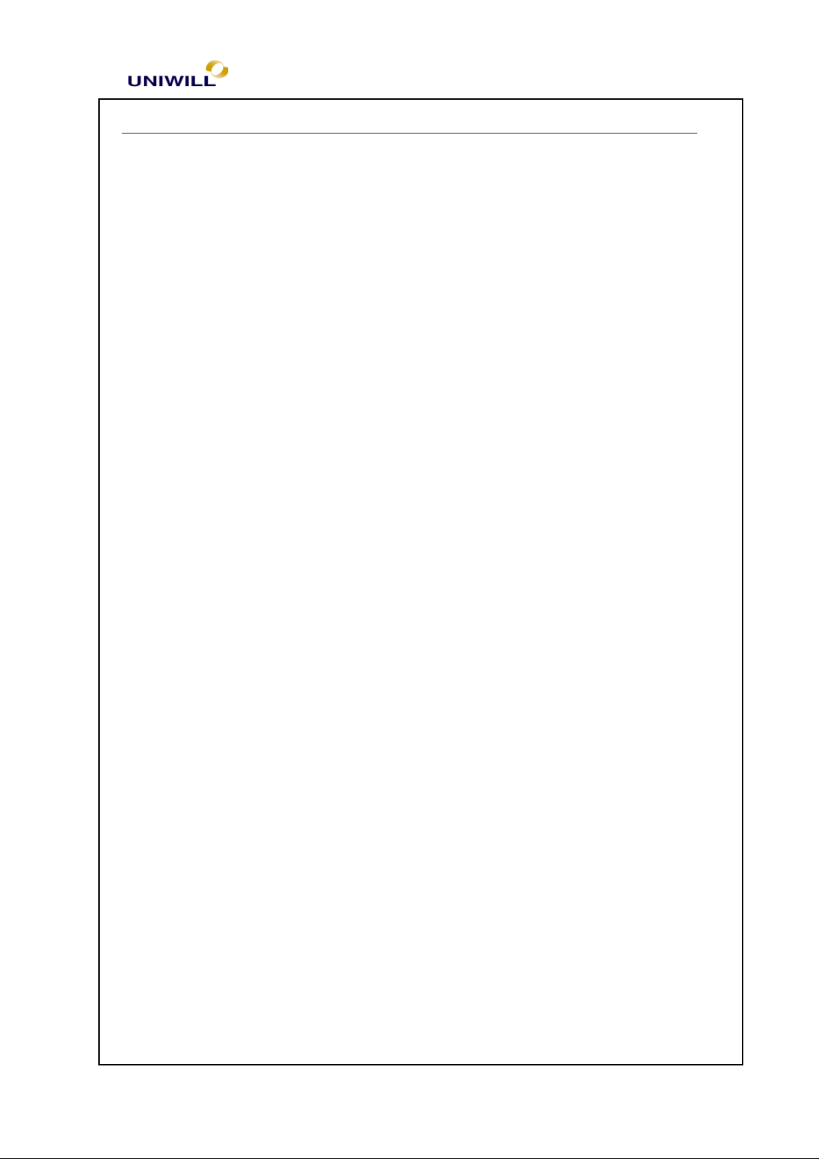
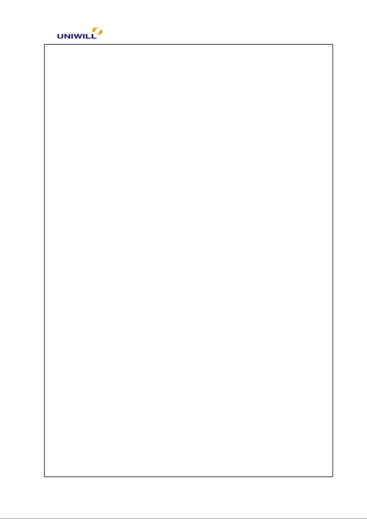
5.1 No display (system failure)
Symptom: There is no display on both LCD and Monitor after power on although
the LCD and Monitor are known-good.
Chapter 5 Troubleshooting Guidelines
N241S1 Rev : A Page 5 - 3
Page 4
No
No
No
No
No Display
Monitor or LCD module ok?
Yes
Set up Display type in BIOS
Display Ok?
Chapter 5 Troubleshooting Guidelines
Replace monitor or LCD
Yes
Setup the display mode
Remove all of I/O device & cables from M/B except LCD or Monitor
Yes
Correct the I/O device & cables to the
Display ok
Replace motherboard
Board level troubleshooting
Check SIS 630S for
any cold solder?
M/B one at a time to find out which
Yes
Re-solder
Check system clock and reset circuit
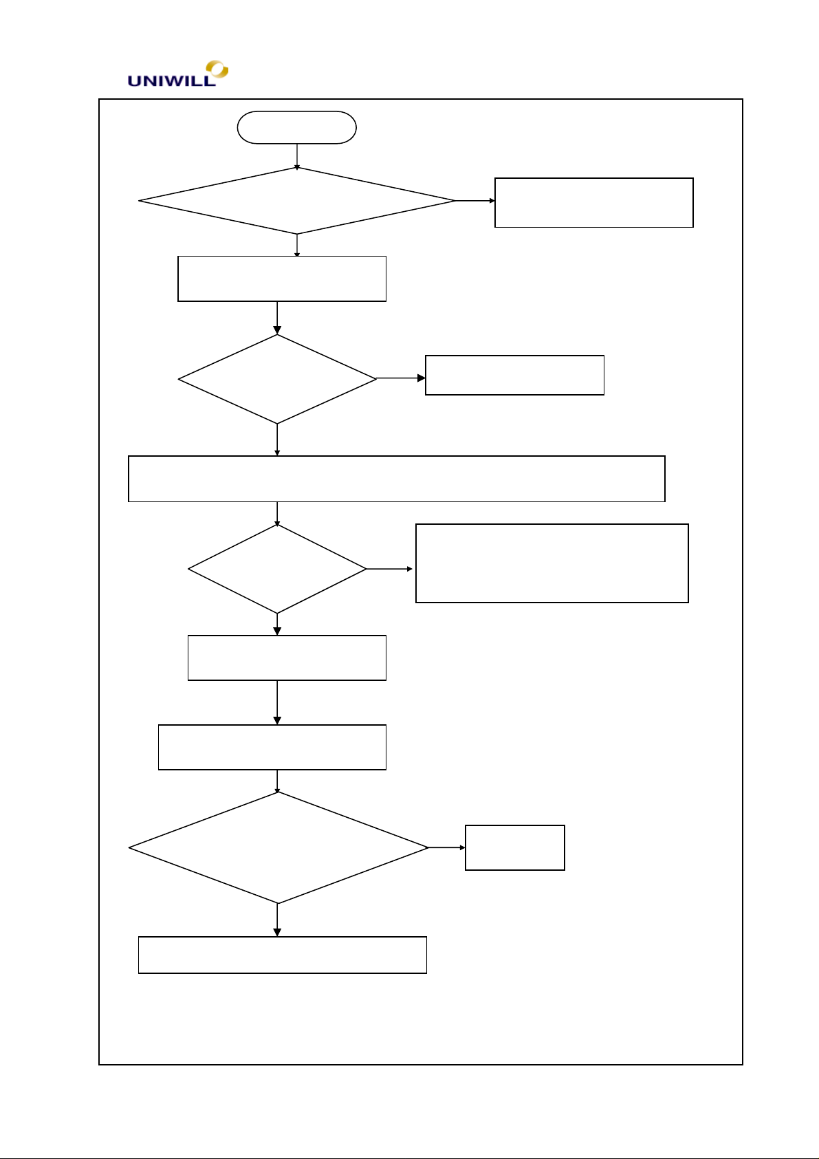
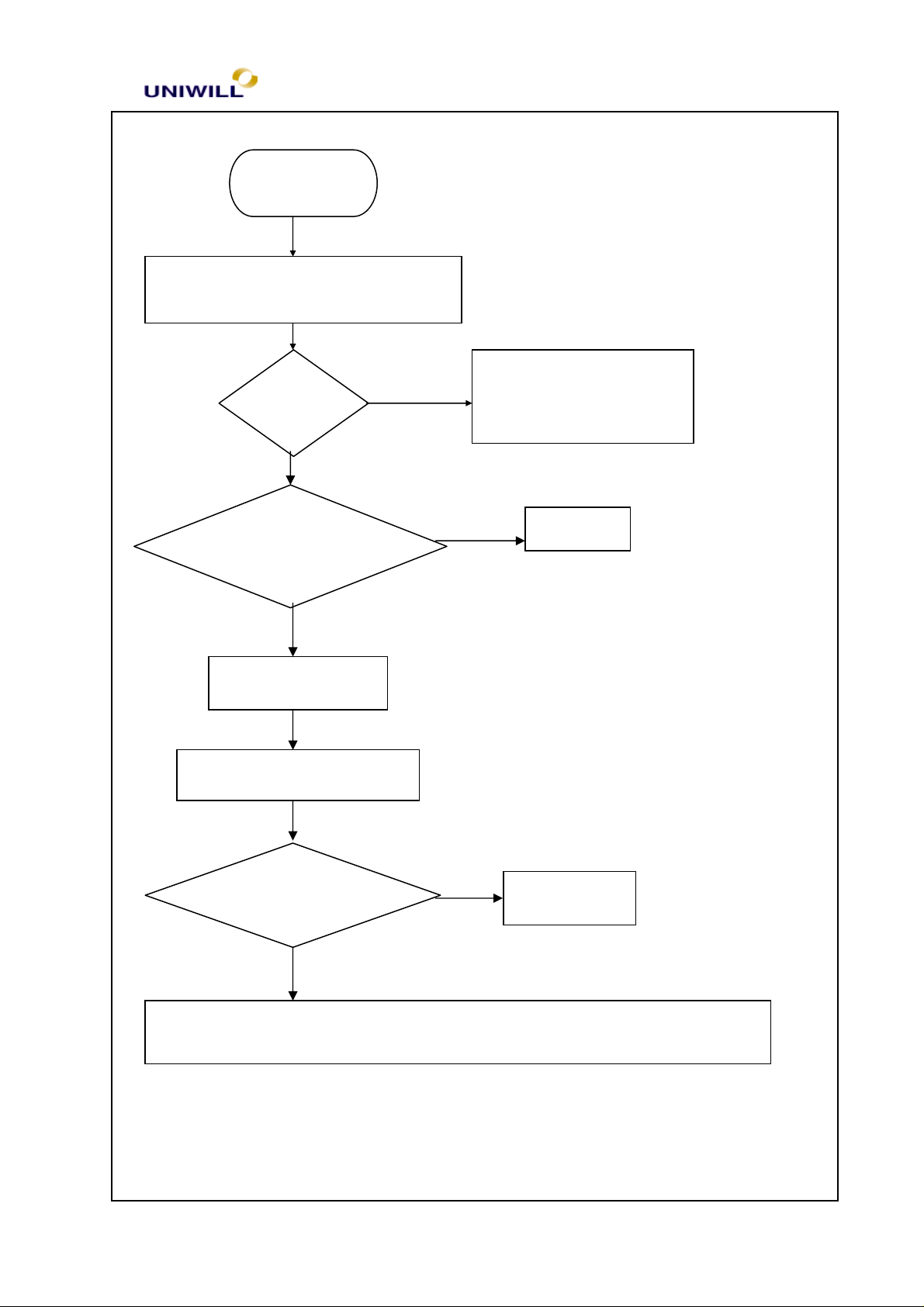
5.2 VGA controller failure
N241S1 Rev : A Page 5 - 4
Page 5
VGA Controller Failure
time to find out which part is causing the problem
controller
for cold solder?
Re-solder
No
No
No
Symptom: There is no display on both LCD and Monitor although
Power-On-Self-Test is passed
Try another good monitor or LCD module
Yes
Display OK
Remove all of I/O devices and cables from M/B except LCD or Monitor
Chapter 5 Troubleshooting Guidelines
Replace faulty LCD or monitor
Yes
Display OK
Replace Motherboard
Board level troubleshooting
Check SIS 630S
Connect the I/O device & cables to the M/B one per
Yes
Replace SIS630S controller or Motberboard
N241S1 Rev : A Page 5 - 5
Page 6
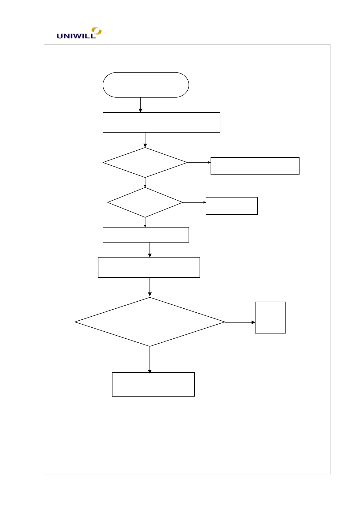
5.3 LCD no display or Invalid Picture
Symptom: The LCD shows nothing or abnormal picture, but it is good for external
monitor.
Chapter 5 Troubleshooting Guidelines
N241S1 Rev : A Page 5 - 6
Page 7
OK?
No
test after each replacement
LCD No Display
Try another known good LCD module
Chapter 5 Troubleshooting Guidelines
Display
Yes
LCD Type correct
in CMOS Setup ?
Yes
Replace
Board level troubleshooting
No
Replace each parts of
LCD module / cables and
test
Correct it
Check LCD module and SIS630S controller, replace the parts one at a time and
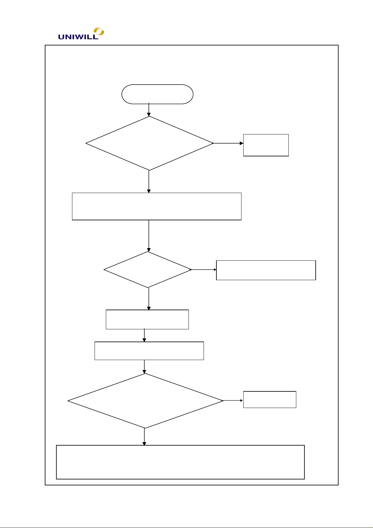
5.4 External monitor has no display or color abnormal
Symptom: The CRT monitor shows nothing or abnormal color, but it is ok for LCD
N241S1 Rev : A Page 5 - 7
SIS 630S Chipset
No
Yes
Re-soldering
Page 8
No
No
Monitor No Display
Try another known good monitor
Display Ok?
Chapter 5 Troubleshooting Guidelines
Yes
Replace faulty monitor
Setup Ok?
Yes
Replace motherboard
Board level Troubleshooting
Yes
Check VGA port signal
using oscilloscope
Correct it
End
Replace SIS 630 S
5.5 Memory test error
N241S1 Rev : A Page 5 - 8
Page 9

module
No
Installed?
and socket OK?
No
No
Memory test error
Chapter 5 Troubleshooting Guidelines
With External
DRAM Module
Yes
Install External
DRAM module
Yes
Try another known good DRAM module
Correct it
Replace motherboard
5.6 Keyboard test error
Test OK?
Yes
Replace the
faulty DRAM
N241S1 Rev : A Page 5 - 9
Page 10

Ok?
Controller PC87570
No
Symptom: error message of keyboard failure is shown or any key doesn’t work
Keyboard test error
Is K/B cable connected to
M/B
properly?
Try another good keyboard
Chapter 5 Troubleshooting Guidelines
No
Correct it
Yes
Yes
KB Test
Replace motherboard
Board level troubleshooting
Check for cold
solder?
Replace the faulty keyboard
Re-soldering
N241S1 Rev : A Page 5 - 10
One of the following parts or signals on the other board
may be defective, use an oscilloscope to check 1.K/B
Page 11
No
No
No
Chapter 5 Troubleshooting Guidelines
5.7 Touch Pad test error
Symptom: An error message is shown when the Touch Pad point is enabled
Touch pad error
Is Touch pad cable
connected properly ?
Yes
Try another known good touch pad module and cabl
Yes
Test Ok ?
Replace the faulty parts
Correct it
e
Replace motherboard
Board level troubleshooting
Yes
Check KB controller
PC87570 for cold solder?
Re-solder
Check one of the following parts or signals on the motherboard maybe
defective, use an oscilloscope and replace it.
N241S1 Rev : A Page 5 - 11
Page 12

5.8 Diskette drive test error
Symptom: An error message is shown while loading data from FDD to system
Chapter 5 Troubleshooting Guidelines
N241S1 Rev : A Page 5 - 12
Page 13

Reboot OK?
Try another known good FDD module
Reboot OK?
Replace motherboard
No
N
No
2. Check set
up for correct settings
Diskette Drive test error
1. Try another known good boot diskette
Chapter 5 Troubleshooting Guidelines
o
Board level troubleshooting
Check FDD connector,
Super I/O controller
Yes
Correct it
Yes
Correct it
Yes
Re-solder
One of the following parts on the M/B may be defective or
poor contact. Replace the parts one at a time and test after
each replacement
FDD Controller (PC87393)
5.9 Hard disk drive test error
Symptom: Either an error message is shown, or the drive motor spins non-stop,
N241S1 Rev : A Page 5 - 13
Page 14

controller for
No
No
No
while reading data from or writing data to Hard disk
Hard disk test error
Check BIOS
HDD Setup OK?
Try another working HDD
Chapter 5 Troubleshooting Guidelines
Yes
Correct it
Re-boot ok?
Replace motherboard
Board level troubleshooting
Check HDD
connector,
PCI-IDE
Yes
Yes
Replace the faulty parts
Re-solder
One of the following parts on the M/B may be detective, replace the
parts one at a time and test after each replacement.1. HDD connector
5.10 CMOS test error
N241S1 Rev : A Page 5 - 14
Page 15

No
1. CMOS data lost, or inaccurate system time & data
CMOS test error
1. Plug in AC adapter, power on the system and set correct data in BIOS setup
2. Turn off power for 1 hour then turn on again
Re-boot OK?
Chapter 5 Troubleshooting Guidelines
Yes
END
Replace motherboard
Board level troubleshooting
Yes
Check CMOS RAM,
CMOS battery for
cold solders
One of the following parts on the motherboard
maybe defective, replace the parts one a time and test
Re-solder
after each replacement:
1.CMOS RAM 2. CMOS battery
N241S1 Rev : A Page 5 - 15
Page 16

SIO test error
Correct it
Correct it
Replace Motherboard
No
Yes
No
No
2. Try another working mouse of I/O device
5.11 SIO port test error
Symptom: An error display occurs when a mouse or other I/O device is installed
1. Check whether mouse or other I/O device are properly
installed (including driver)
Re-test Ok?
Chapter 5 Troubleshooting Guidelines
Setup OK?
Yes
Board level troubleshooting
Check SIO
controller for
Yes
Re-solder
One of the following parts on the motherboard maybe defective, plug SIO
loopback at SIO port and run SIO test program. If error, replace SIO controller
N241S1 Rev : A Page 5 - 16
Page 17

Correct it
Correct it
cold solder?
No
No
No
5.12 PIO port test error
Symptom: When a print command is issued, printer prints nothing or garbage.
PIO test error
1. check whether cables, printer & printer driver are installed properly
2. try another working printer and cable
Chapter 5 Troubleshooting Guidelines
Re-test OK?
Setup OK?
Yes
Replace motherboard
Board level troubleshooting
Yes
Check PIO
controller, for
One of the following parts on the motherboard maybe defective, plug
PIO loopback at PIO port one a time and test, if error replace PIO
controller
N241S1 Rev : A Page 5 - 17
Yes
Re-solder
Page 18

Chapter 5 Troubleshooting Guidelines
5.13 Audio failure
Symptom: No sound from speaker after audio drive is installed.
N241S1 Rev : A Page 5 - 18
Page 19

Audio test error
Replace motherboard
No
No
No
1. check whether cables, speakers & audio drivers are installed properly
2. try another working speaker & cable
Re-test ok?
Setup ok?
Chapter 5 Troubleshooting Guidelines
Yes
Correct it
Correct it
Yes
Board-level troubleshooting
Check SIS 630S
Chipset for cold
Solder
One of the following parts on the motherboard may be defective, replace the
SIS 630S Chipset
Yes
Re-soldering
5.14 No power symptom:
N241S1 Rev : A Page 5 - 19
Page 20

No
Symptom: When the power button is pressed, nothing happens, power indicator
is not light up.
No Power
Check Fuse on MB if open
Chapter 5 Troubleshooting Guidelines
Yes
Replace it
Check MB Board power
Signal or replace each
parts.
No
Press Power on button again
Check power LED lit on
Yes
Correct it
N241S1 Rev : A Page 5 - 20
Page 21

Chipset
for cold solder?
5.15 CD-ROM drive test error
An error message is shown when reading data from CD-ROM drive
CDROM Failure
Check drive is install
OK?
Chapter 5 Troubleshooting Guidelines
No
Correct it
Yes
Check cable & Door is
closed
Yes
Replace Motherboard
Board Level Troubleshooting
Check SIS 630S
and CDROM connector
No
Correct it
Yes
Re-soldering
No
Check one of the following parts or signal on the M/B
may be defective, use an oscilloscope to check it.
N241S1 Rev : A Page 5 - 21
Page 22

5.16 Stopping in LCD screen while booting
Chapter 5 Troubleshooting Guidelines
N241S1 Rev : A Page 5 - 22
Page 23

Check HDD detection
Record LCD message & to
No
No
No
Stop in LCD Screen while
booting
Chapter 5 Troubleshooting Guidelines
Check Memory
Size is correct?
Yes
is OK?
Yes
Check CD-ROM
Detection is OK?
Yes
No
Board–level
Troubleshooting
Make sure HDD is good
&Check BIOS setting
Make sure CD-ROM
Is good & Check BIOS
Settings
Stop in LCD screen while booting
Check CPU &
SIS630S for cold
Yes
Check one of the following parts or signal on the M/B may
be defective, use an oscilloscope to check it.
5.17 PCMCIA CardBus failure
Re-soldering
N241S1 Rev : A Page 5 - 23
Page 24

Insert PCMCIA card completely again,
controller install OK?
soldering?
No
Yes
No
Symptom : when insert PCMCIA card to PCMCIA slot, but system can’t
detect.
PCMCIA card failure
make sure good connection.
Chapter 5 Troubleshooting Guidelines
Check drive &
Board-level Trouble shooting
Check PCMCIA slot
mounting in M/B is cold
Correct it
Yes
Re-soldering
N241S1 Rev : A Page 5 - 24
Check O2Micro OZ
6812 Chipset for cold
No
Replace O2Micro OZ6812
chipset
Yes
Re-solder
Page 25

Check PC87393 for cold
d
evice
Check BIOS setup OK?
No
No
Yes
No
Yes
No
5.18 IR Port can’t transfer data.
IR failure & no response
Chapter 5 Troubleshooting Guidelines
Correct it
Yes
Check driver install OK
Check another one IR
device is meet IrDa 1.0
Board-level trouble shooting
soldering
Correct it
Try another IR
Yes
Re-soldering
N241S1 Rev : A Page 5 - 25
Replace Super I/O PC97393 Chipset
Page 26

setting is OK?
No
Yes
No
No
Check modem DAA board is
No
5.19 Modem failure
Chapter 5 Troubleshooting Guidelines
Check Driver install &
Telephone Line is OK?
Check IRQ, COM port
AT command test
modem function is OK
Yes
Correct it
Correct it
Re-install Drivers
Board-level trouble shooting
connected properly and
wiring with the phone jack
Yes
Replace another known good modem
DAA module.
Connect it
N241S1 Rev : A Page 5 - 26
 Loading...