

Page 1

INSTRUCTION
VS9/VS9H
MANUAL
VEGETABLE SLICER
WE THANK YOU FOR YOUR PURCHASE OF OUR
MODEL VS9/VS9H VEGETABLE SLICER.
VS9494/ ED3
Page 2

TABLE OF CONTENTS
DESCRIPTION PAGE
TABLE OF CONTENTS 1
LIST OF DIAGRAMS 1
LIST OF ILLUSTRATIONS 1
INTRODUCTION 2
SAFETY PRECAUTIONS 2
INSPECTION AND MODEL VARIATION EXPLANATION 3
INSTALLATION 3
OPERATOR'S INSTRUCTIONS 3-7
PLATE UNITS - ASSEMBLY - USE 4
GRATER, SHREDDER AND JULIENNE PLATE UNITS 4
LOADING PLATE UNITS INTO VS9 HOUSING 5
MOUNTING INSTRUCTIONS 6
PROCESSING PRODUCT 7
DISMOUNTING AND DISASSEMBLY FOR CLEANING 7
LUBRICATION 8
MECHANIC'S MAINTENANCE 9
TROUBLE SHOOTING GUIDE 9
REPLACEMENT PARTS AND ASSEMBLIES 11-13
DIAGRAMS
DIAGRAMS
DIAGRAM 1
DIAGRAM 2 PROPERLY LOADED VS9/VS9H 5
DIAGRAM 3 TYPICAL POWER TAKE-OFF HUB 6
DIAGRAM 4 MOUNTING ANGLE 6
DIAGRAM 5 PROPER ASSEMBLY OF THE SLICER PLATE ASSEMBLY 10
SLOT AND PIN ALIGNMENT 4
LIST OF ILLUSTRATIONS
PAGE
ILLUSTRATION PAGE
FIGURE 1 VS9/VS9H HOUSING ASSEMBLY 11
FIGURE 2 KNIFE & SHAFT ASSEMBLY 12
FIGURE 3 GRATER, SHREDDER and JULIENNE PLATE ASSEMBLY 13
PAGE 1
Page 3

INSTRUCTION MANUAL
replacement parts list with identifying figure diagrams is included to aid in identification and ordering of replacement parts. Please review
Food to be
processed must always be fed to cutting surfaces by way of the hopper, and compressed against cutting surfaces with the feed
is under power, and again, never insert fingers or utensils into the
knives, cutting plates, or cutting assemblies. They are very sharp and can
make sure it rests on a stable working surface. Never rest knives, cutting plates,
and mounting it to power source equipment, make sure that a comfortable working clearance has
to power source equipment, review the power source equipment manual for instruction on the use of
if there is no securing device present
INTRODUCTION
This manual contains instructions for the inspection, installation, safe operation, care, and maintenance of the VS9 Vegetable Cutter.
Disassembly, repair, replacement, and re-assembly instructions are included. A trouble shooting guide is provided. A complete
this manual carefully - particularly all safety precautions -before trying to put the VS9 into service.
SAFETY INSTRUCTIONS
- Never insert hands into the hopper.
- Never insert any utensil into the hopper.
1. Note that the front housing of the VS9 has a feed hopper [Fig. 1 (2)]. It is also equipped with a feed plate [Fig. 1 (8)].
plate. Never try to feed product to cutting surfaces with your hands or any other way!
2. If during operation of a product jam occurs, immediately turn off and disconnect the electrical supply to the power source
equipment. Make sure rotation has stopped. Unlatch the VS9's front housing, swing it toward you, and then clear the
obstruction. Do not try to clear obstructions while the VS9
hopper!
3. Wear protective gloves whenever handling the VS9's
cut you. For safety, wash knives and cutting plates with a long handled scrub brush.
4. When assembling or disassembling the VS9,
or cutting assemblies on surfaces that could be marred.
5. Before assembling the VS9
been provided around the machinery. Always install the machinery where it will save the operator steps.
6. Before assembling the VS9 and mounting it to power source equipment, or dismounting the VS9 after use, disconnect or lockout the electrical supply to the power source equipment. This will prevent any chance of accidental start-up.
7. Before mounting the VS9 to power source equipment, make sure the front housing [Fig. 1 (8)] is securely latched to the rear
housing [Fig. 1 (9), (10), (11)].
8. Before mounting the VS9
its power take-off hub. The hub should be equipped with a thumb screw. The thumb screw should be firmly snugged
immediately after mounting the VS9 to secure the VS9 in place. Do not operate the VS9
on the power take-off hub.
9. Never hose down a VS9 mounted to power source equipment. Hosing down a mounted VS9 invites electrical shock.
PAGE 2
Page 4

INSPECTION AND MODEL VARIATION EXPLANATION
CUTTER
APPLICATION
MIXING MACHINE SPEED
The Univex VS9 is tested and inspected at the factory. The standard VS9 comes equipped with
only the slicer plate assembly illustrated in Figure 2. the VS9H comes equipped with the hub and
shaft assembly illustrated in Figure 3, and one 3/16" shredder plate. The remaining plates are
optional purchase items. The person making the installation should re-inspect the VS9/VS9H
immediately upon receipt for loose, damaged, or missing parts. Any damages should be reported
to the carrier immediately, and any shortage of parts to Univex Corporation.
INSTALLATION
The Univex VS9 is an attachment with no internal power source. To function, it must be mounted
to a food mixing machine or a power base unit. Again, make sure that a comfortable working
clearance is provided around the machinery, and that the machinery is installed where it will save
the operator steps. Make sure the power source equipment power take-off assembly includes a
thumb screw or other means of securing the VS9 in place (see Diagram 3).
OPERATOR'S INSTRUCTIONS
SLICING, GRATING, AND SHREDDING
The Univex VS9 is designed to slice, grate, and shred a wide range of food products when fitted
with the proper plates and operated at the proper speeds. Before mounting the VS9 to power
source equipment, refer to the application chart below. If the power source equipment is a power
base unit, your choice of operating speeds is limited.
Slicer Plate Cole slaw, potatoes, fruits, vegetable.
Adjusting nut (Fig. 2, 6) is turned to set slice
thickness. Prior to slicing cabbage or head
lettuce, quarter the heads and remove cores.
Firm heads process a better product
Julienne Plate French fried potatoes, carrots, turnips, beets,
salads, etc.
Grater Plate Grated nutmeg, cheese, coconut, bread,
cracker crumbs.
Shredder Plate Various coarsenesses of cheese, carrots, etc. Medium speed, indicator setting "2".
CONTROL SETTING
High speed, indicator setting "2".
Medium speed, indicator setting "2".
Medium speed, indiactor setting "2".
NOTE: For best results keep knives very sharp.
PAGE 3
Page 5
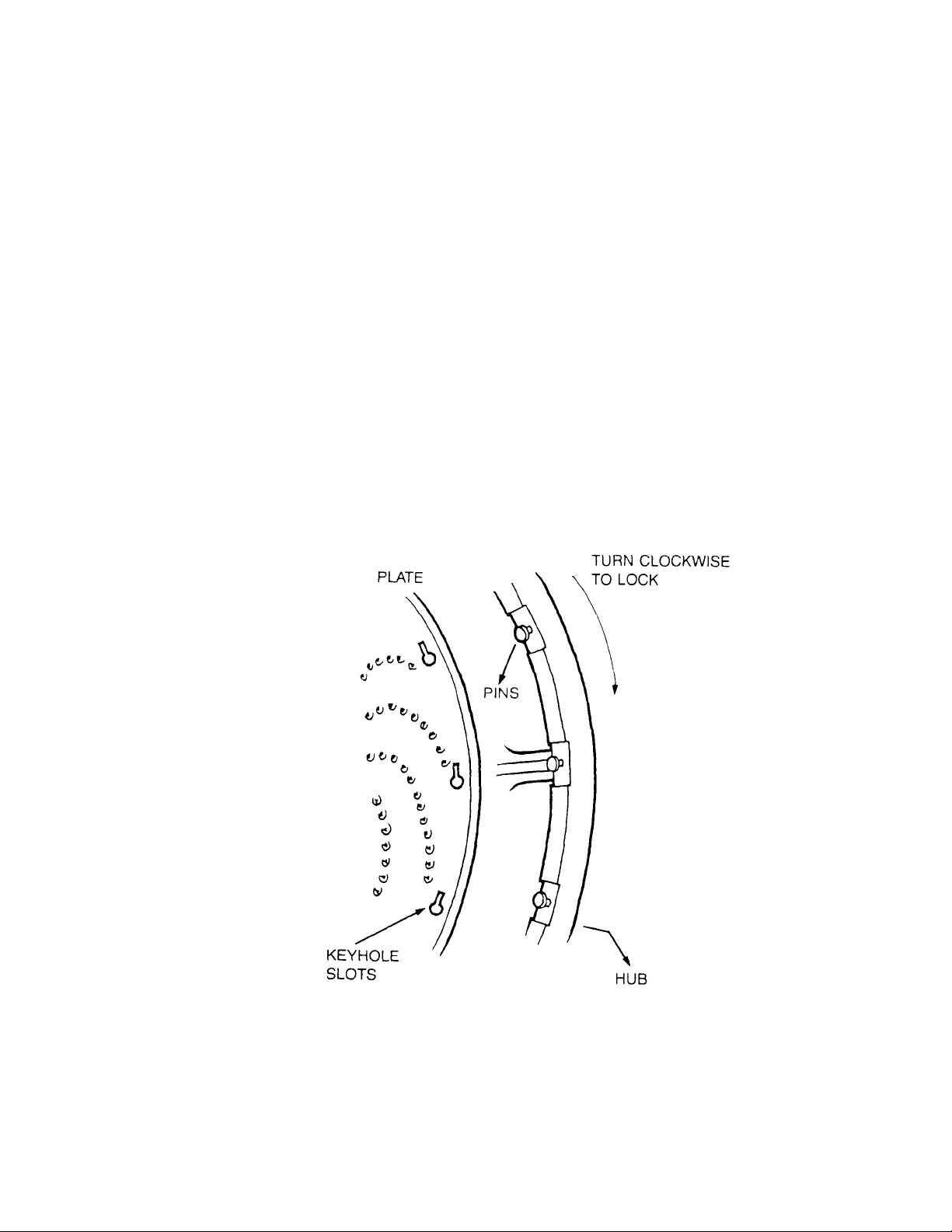
PLATE UNITS - ASSEMBLY AND USE
embled, can be
CAUTION: Again, wear hand protection when working with these units.
THE ADJUSTABLE SLICER PLATE UNIT -
To assemble the slicer plate, see Figure 2 and Diagram 5 component assembly order and fit as shown. The plate, when ass
adjusted to slice product to different thicknesses by turning the "adjusting nut" per the directions accompanying Diagram 5.
WARNING: Adjustments for thickness must never be attempted while the VS9 is under power or severe personal injury can occur. See
safety precautions - Paragraph 2.
GRATER, SHREDDER AND JULIENNE PLATE UNITS [Figure 3]
To fit the plate of your choice to the hub and shaft [Figure 3], line up the key hole slots on the plate with the locating pins on the hub as
shown below. Slip the plate over the pins and secure it by turning the plate in a clockwise direction until it shoulders up firmly on the pins.
This can be done most safely by resting the plate face down on a butcher's block and turning the hub home from above.
DIAGRAM 1 SLOT AND PIN
ALIGNMENT
Make sure that the "Thrust Bearing" [Figure 3 (3)] is properly positioned on the shaft. Make sure that the set screw
[Figure 3 (2)] on the thrust bearing is securely snugged. A loose thrust bearing will allow clatter and damage the VS9.
Do not remove thrust bearing for cleaning.
PAGE 4
Page 6

LOADING PLATE UNITS INTO THE VS9 HOUSING
1 (19)] and seat the plate unit with a gentle twist.
Make sure that the thrust bearing on the shaft has carried fully into place, and that the square milled end of the shaft has fully cleared the
With the VS9 resting on a stable working surface, unlatch the front housing [Figure 1 (8)] and swing it toward you. Lift the assembled
plate unit and insert it into the rear housing [Figure 1 (10)]. Lift the shaft lock pin [Figure
rear hub [Figure 1 (15)]. Release the shaft lock pin, then close and securely latch the front housing.
The VS9 is now ready to mount to power source equipment.
DIAGRAM 2
PROPERLY LOADED VS9/VS9H
PAGE 5
Page 7

MOUNTING THE VS9 TO POWER SOURCE EQUIPMENT
make sure that the power source equipment is turned off and its electrical supply disconnected or locked
and insert the square milled shaft end into the hub intake
tapered hub is
Again, before mounting the VS9,
out. Review the power take-off hub information in the manual for the power source equipment, then proceed as follows:
DIAGRAM 3
TYPICAL POWER TAKE-OFF HUB
Remove the chrome cover cap from the power take-off hub. Carefully lift the VS9
port (See diagram above), while holding the VS9 at the angle pictured below.
Slide the VS9 forward until the square milled shaft end firmly seats in the PTO adaptor [Diagram 3]. Gently twist the VS9 to a fully upright
position, slide locating pin [Figure 1(17)] into PTO locating hole and snug the thumb screw [Diagram 3 ]. NOTE: Only the #12
fitted with a locating pin. the VS9 is now ready to process product.
DIAGRAM 4
MOUNTING ANGLE
(NOT OPERATING ANGLE)
PAGE 6
Page 8

PROCESSING PRODUCT
is equipped with
pment on, and where possible adjust the speed of
up or down
t through a dishwashing machine. Wearing hand protection,
Before processing product, please review the application chart on Page 3, and please note that the feed plate [Figure 1(2)]
an adjusting nut and screw [Figure 1(6-7)]. This assembly should be adjusted until there is no chance of the feed plate being compressed
against cutting surfaces. If the feed plate meets a rotating cutting surface, both components will be damaged.
TO PROCESS:
Reconnect the electrical supply to the power source equipment, turn the power source equi
the power source equipment to a medium setting.
Lift the feed plate to expose the plate unit, and drop product into the feed hopper. Keep hands clear. With your hand holding the feed plate
grip, gently compress product against the rotating plate unit. Adjust the speed of the power source equipment - where possible until you get the best results.
If you experience problems in processing, shut down the power source equipment and refer to the Trouble Shooting Guide on Page 9, and
the safety precautions paragraph.
DISMOUNTING AND DISASSEMBLY
FOR CLEANING AND MAINTENANCE
DISMOUNTING
To dismount the VS9, simply follow the mounting instructions on Page 6 in reverse order. Set the VS9 on a stable working surface.
DISASSEMBLY
To disassemble the VS9 for cleaning or maintenance:
Unlatch the front housing and swing it toward you.
Lift the feed plate up and urge it to the left until it pivots off the front housing and set it aside.
Lift the front housing from its pivot holes and set it aside.
To disassemble the plate units, follow the assembly instructions on Pages 4-6 in reverse order. Set the components aside.
CLEANING
To avoid damaging the VS9's highly polished finish, never put any VS9 componen
wash all components by hand with a mild soap and water solution. Use a long handled scrub brush on all plate units to avoid finger cuts.
Again, do not rest knives, grater plates, or shredding plates on any surface which will mar. Do not remove thrust bearings from Julienne or
Shredder plate shafts. Dry component parts with a soft dry rag.
For the best and most sanitary product, clean the VS9 immediately after use of before switching food products.
PAGE 7
Page 9

PROCESSING PRODUCT
is equipped with
pment on, and where possible adjust the speed of
up or down
t through a dishwashing machine. Wearing hand protection,
Before processing product, please review the application chart on Page 3, and please note that the feed plate [Figure 1(2)]
an adjusting nut and screw [Figure 1(6-7)]. This assembly should be adjusted until there is no chance of the feed plate being compressed
against cutting surfaces. If the feed plate meets a rotating cutting surface, both components will be damaged.
TO PROCESS:
Reconnect the electrical supply to the power source equipment, turn the power source equi
the power source equipment to a medium setting.
Lift the feed plate to expose the plate unit, and drop product into the feed hopper. Keep hands clear. With your hand holding the feed plate
grip, gently compress product against the rotating plate unit. Adjust the speed of the power source equipment - where possible until you get the best results.
If you experience problems in processing, shut down the power source equipment and refer to the Trouble Shooting Guide on Page 9, and
the safety precautions paragraph.
DISMOUNTING AND DISASSEMBLY
FOR CLEANING AND MAINTENANCE
DISMOUNTING
To dismount the VS9, simply follow the mounting instructions on Page 6 in reverse order. Set the VS9 on a stable working surface.
DISASSEMBLY
To disassemble the VS9 for cleaning or maintenance:
Unlatch the front housing and swing it toward you.
Lift the feed plate up and urge it to the left until it pivots off the front housing and set it aside.
Lift the front housing from its pivot holes and set it aside.
To disassemble the plate units, follow the assembly instructions on Pages 4-6 in reverse order. Set the components aside.
CLEANING
To avoid damaging the VS9's highly polished finish, never put any VS9 componen
wash all components by hand with a mild soap and water solution. Use a long handled scrub brush on all plate units to avoid finger cuts.
Again, do not rest knives, grater plates, or shredding plates on any surface which will mar. Do not remove thrust bearings from Julienne or
Shredder plate shafts. Dry component parts with a soft dry rag.
For the best and most sanitary product, clean the VS9 immediately after use of before switching food products.
PAGE 7
Page 10

LUBRICATION INSTRUCTIONS
1-800-258-6358
Enclosed is a sample tube of Petro-Gel which we recommend you use in all your food preparation equipment.
It may be purchased at your local food equipment supply company, or purchased directly from: (Part No. 4400408)
Univex Corporation
3 Old Rockingham Road
Salem, NH 03079
LUBRICATION
After every cleaning, apply a thin coating of sterile petroleum jelly to all bearing surfaces. Do not use vegetable oil. It
becomes gummy. If adjusting nuts and screw become stiff to work with, apply a drop of sterile mineral oil.
PAGE 8
Page 11

MECHANICS MAINTENANCE
disassembly instructions on
urce, most problems can be immediately traced to improper assembly, improper adjustment or
Power source equipment is under power
Before trying to maintenance the VS9, review the safety precautions paragraph carefully, and read all assemblyPages 2-6. Wear gloves when handling plate units.
Since the VS9 contains no internal power so
worn parts. The Trouble Shooting Guide on Page 7 lists the most common problems and corrective measures.
REPLACEMENT PARTS AND ASSEMBLIES
Replacement parts and assemblies are displayed in Figure 1 through 3. When ordering, always include Univex part numbers and item
descriptions. Common hardware parts are identified in normal nomenclature.
TROUBLESHOOTING GUIDE
Caution: Review all safety notes and disconnect electricity
to power source equipment before attempting corrective measures.
TROUBLE POSSIBLE CAUSE SOLUTION
1.
but plate will not turn.
2. Knife or plate scraping front housing. Thrust bearing loose, or lock pin not fully
3. Shredding plates loose or rattling. Plate is loose on hub pins. Inspect shredder plate assembly to assure
4. Front housing will not shut tightly. Latch set screw out of adjustment. Adjust set screw at rear of latch [Figure
5. Mounted VS9 unit rattles when under
power.
6. Feed plate scraping plates. Feed plate adjusting unit out of
PTO adaptor missing from power take-off
assembly
engaged.
Thumb screw or securing mechanism on
power take-off assembly missing or too
loose.
adjustment.
Replace PTO adaptor.
Tighten thrust bearing immediately, make
sure lock is properly engaged pin.
plate is shouldered firmly up on pins.
Inspect shredder plate to assure it is not
bent
1(12)].
Tighten or replace.
Back off feed plate adjusting nut.
PAGE 9
Page 12

DIAGRAM 5
PROPER ASSEMBLY OF THE SLICER PLATE ASSEMBLY
CAUTION: The thrust bearing must be securely tightened before the slicer plate assembly is loaded into the housing.
Failure to tighten will damage the VS9 and the power source equipment.
NOTE: The thrust bearing requires a left hand twist to tighten.
PAGE 10
Page 13

VS9/VS9H HOUSING ASSEMBLY
1
1
1
1
1
1
1
1
1
1
1
1
1
1
1
1
1
FIGURE 1
ILLUS. NO. PART NO. DESCRIPTION QTY.
1. 4400028 PUSHER PIN - LEFT 1
2. 1000903 FEED PLATE
3. 4400097 NYLON WASHER 1/2" O.D. X 1/8" X 3/8" I.D.
4. 4400029 PUSHER PIN - RIGHT
5. 0090004 HINGE PINS 2
6. 4400057 STOP NUT 1/4-20
7. 1200025H SET SCREW 1/4-20 X 3/4"
8. 1000902 FRONT HOUSING
9. 4400400 DOWEL PIN 1/4" X 1" S/S
10. 1000901 REAR HOUSING
11. 1000806 LATCH
12. 4400193 SET SCREW 10-32 X 3/8"
13. 1200377 WASHER, BEVEL 5/16" I.D.
14. 0090000 LATCH SCREW
15.* 1000918 #12 TAPERED HUB (STANDARD) 1
0090005 UNIVEX REAR HUB (OPTIONAL)
16. 4400091 PAN HEAD SCREW 1/4-20 X 5/8" 6
17. 0090002 LOCATING PIN 5/16" X 1"
18. 4400184 FULL DOG SET SCREW 5/16" -24 X 1/2
19. 1000811 SHAFT LOCK PIN (INCLUDES 4400180)
20. 1000914 BRONZE BUSHING
21. 1000923 PLASTIC BUTTON - FRONT COVER
* When ordering, specify #12 tapered hub or Univex rear hub. The Univex rear hub does not have accommodation for a locating pin
(17), and will only fit older Univex manufactured power source equipment.
PAGE 11
Page 14

KNIFE AND SHAFT ASSEMBLY
FIGURE 2
ILLUS. NO. PART NO. DESCRIPTION QTY.
1.* 1000922 KNIFE 1
2.* 4400004 ROLL PIN 1/4" X 1-1/8" 1
3.* 4400092 DRIVE PIN 1
4.* 1000820 DRIVE SHAFT 1
5.* 1000904 PLATE ADJUSTING 1
6. 1000808 NUT - ADJUSTING 1
7. 1000917 SPRING - NUT ADJUSTING 1
8. 1000809 BEARING - THRUST 1
* Illustrations I through 5 are presented for illustration purposes only Replacement of any one of those illustrated parts requires the
replacement of all five. They may be purchased as Assembly No. 1000912.
PAGE 12
Page 15

SHREDDER PLATE ASSEMBLY
are presented for illustration purposes only. Replacement of any one of those illustrated parts requires the
WITH OPTIONAL PLATES
FIGURE 3
ILLUS. NO. PART NO. DESCRIPTION QTY.
1.* 1000116 SHAFT 1
2.** 1200036 SET SCREW 5/16" -24 X 3/8" 1
3.* 1000973 THRUST BEARING 1
4.* 4400116 ROLL PIN 3/16" x 1-1/2" 1
5.* 1000975 PLATE PINS 8
6.* 1000115 PLATE HOLDER 1
7. 1000906 GRATER PLATE OPTIONAL
8. 1000907 SHREDDER PLATE 3/32" DIA OPTIONAL
9. 1000908 SHREDDER PLATE 1/2" DIA OPTIONAL
10. 1000909 SHREDDER PLATE 3/16" DIA. OPTIONAL
11. 1000910 SHREDDER PLATE 5/16" DIA. OPTIONAL
12 1000911 JULIENNE PLATE OPTIONAL
* Illustrations 1, 4, 5, and 6
replacement of all. They may be purchased as Assembly No 1000913.
** Illustration 2 must be purchased with Illustration 3.
PAGE 13
 Loading...