

Page 1
VS2000 VEGETABLE
SLICER/SHREDDER
OPERATOR’S MANUAL
Persons under age 18 are not permitted to operate or have accessibility to
operate this equipment per U.S. Dept. Of Labor Employment Standards
Administration Fact Sheet No. ESA913.
VS2000 REV A
Page 2

TABLE OF CONTENTS
DESCRIPTION PAGE
TABLE OF CONTENTS...........................................................................................................1
LIST OF ILLUSTRATIONS .....................................................................................................1
INSPECTION ............................................................................................................................2
SAFETY .................................................................................................................................3-4
OPERATING INSTRUCTIONS ...............................................................................................6
VEGETABLE PREPARATION ATTACHMENT VS9.............................................................7
GRATING AND SHREDDING ATTACHMENT VS9H ..........................................................8
PLATE UNIT ASSEMBLY AND USE .....................................................................................9
GRATER, SHREDDER AND JULIENNE PLATE ASSEMBLY...........................................10
LOADING PLATES INTO THE VS9/VS9H HOUSING.......................................................11
PROCESSING PRODUCT .....................................................................................................12
DISMOUNTING AND DISASSEMBLY ...............................................................................12
CLEANING .............................................................................................................................13
LUBRICATION INSTRUCTIONS .........................................................................................13
TROUBLE SHOOTING GUIDE ............................................................................................14
WARRANTY .....................................................................................................BACK COVER
LIST OF ILLUSTRATIONS
ILLUSTRATION PAGE
FIGURE 1 OVERALLVIEW..................................................5
FIGURE 2 POWER TAKE-OFF HUB (PTO) .....................................6
FIGURE 3 VS9 SLICING ATTACHMENT .......................................7
FIGURE 4 ADJUSTABLE“S”KNIFEASSEMBLY ...............................7
FIGURE 5 VS9HGRATING/SHREDDINGATTACHMENT .......................8
FIGURE 6 ASSEMBLY OF SLICER PLATE .....................................9
FIGURE 7 PLATEINSTILLATION ...........................................10
FIGURE 8 PROPERLY LOADED VS9/VS9H ...................................11
FIGURE 9 LUBRICATION INSTRUCTIONS ...................................13
Page 1
Page 3

UNIVEX VS2000 HIGH VOLUME VEGETABLE SLICER/SHREDDER
INSTRUCTION MANUAL
Welcome to Univex
Thank you for purchasing this Univex Product.
Your new PM91 Prep-Mate has been designed with advanced performance and safety features that make it an
excellent addition to your food preparation equipment. Like all Univex mixers, slicers, meat grinders and
accessories, this power unit is engineered to provide years of reliable service.
If you have any questions concerning the operation of this unit, or if we can be of further assistance, please
call our Customer Service Department for the location of your nearest service representative.
Univex Customer Service:
USA & Canada 800-256-6358
International 603-893-6191
Or visit us on-line at www.univexcorp.com under service agents.
The UNIVEX VS2000 HIGH VOLUME VEGETABLE SLICER/SHREDDER is a 1 HP portable
electric unit consisting of a poly “V” belt assembly with a No. 12 drive hub operating at 7000 rpm. It is
designed to support and power the UNIVEX VS9 vegetable slicer, and the VS9H shredder and grater
food processing attachments.
INSPECTION
The VS2000 drive assembly has been inspected and tested at the factory, however the user should
perform an external inspection and electrical check prior to use. The electrical data listed on the
nameplate of the drive unit should be the same as the user’s electrical supply. Any damage should be
reported to the carrier immediately and any shortage or deviation of parts should be reported to Univex
Corporation.
Page 2
Page 4

SAFETY IS OUR TOP PRIORITY
READ AND MAKE SURE THAT YOU UNDERSTAND THE INSTRUCTIONS AND SAFETY
WARNINGS IN THIS BOOKLET BEFORE ATTEMPTING TO OPERATE THIS POWER UNIT.
IT IS A VIOLATION OF UNITED STATES DEPARTMENT OF LABOR REGULATIONS TO PERMIT
OPERATION OF THIS UNIT BY ANY PERSON UNDER THE AGE OF 18 YEARS.
FIRST TIME OPERATORS SHOULD BE PROPERLY TRAINED IN SAFETY PRECAUTIONS AND IN
THE PROPER USE AND SERVICING OF THIS EQUIPMENT AND ATTACHMENTS.
SWITCH THE POWER “OFF” BEFORE CONNECTING THE UNIT TO THE POWER SOURCE, OR
RESETTING THE CIRCUIT BREAKER (CANADA ONLY). MAKE SURE THE SWITCH IS IN THE
OFF POSITION OR THE MACHINE WILL START WHEN POWER IS RESTORED.
A MANUAL RESETTABLE OVERLOAD CIRCUIT BREAKER (CANADA ONLY) IS PROVIDED ON
THE BACK OF THE MACHINE. IF THE CIRCUIT BREAKER (CANADA ONLY) IS TRIPPED, SWITCH
THE POWER “OFF”, DISCONNECT THE ELECTRICAL POWER SUPPLY CORD, DETERMINE THE
AND CORRECT THE FAULT AND RESET THE BREAKER (CANADA ONLY).
WHEN THE UNIT IS NOT IN USE, PLACE THE ON/OFF SWITCH IN THE “OFF” POSITION AND
REMOVE THE SWITCH KEY BY PINCHING THE KEY BETWEEN THE THUMB AND FOREFINGER AND PULLING IT FROM THE SWITCH. REMOVING THE KEY WILL PREVENT THE SWITCH
FROM BEING SET TO THE “ON” POSITION.
SWITCH THE POWER “OFF” AND DISCONNECT THE POWER SUPPLY CORD BEFORE MOUNTING OR DISMOUNTING ANY ATTACHMENT OR FOR CLEANING OR SERVICING THE UNIT
BE SURE ANYATTACHMENTS ARE PROPERLY CLEANED, ASSEMBLED AND INS
TIGHTEN THE THUMB SCREW BEFORE CONNECTING THE POWER SUPPLY CORD.
WIPE DOWN THE EXTERIOR OF THE DRIVE UNIT ONLY, NEVER HOSE DOWN OR IMMERSE
THE DRIVE UNIT IN WATER.
DO NOT ATTEMPT TO SERVICE THE DRIVE ASSEMBLY. PLEASE CONTACT UNIVEX
CORPORATION FOR THE NUMBER OF THE NEAREST AUTHORIZED SERVICE AGENT IN YOUR
AREA FOR ADJUSTMENTS OR REPAIR.
NEVER INSERT HANDS OR UTENSILS INTO THE HOPPER.
FOOD TO BE PROCESSED IN THE VS9 MUST ALWAYS BE FED TO THE CUTTING SURFACES BY
WAY OF THE HOPPER, AND PRESSED AGAINST THE CUTTING SURFACE WITH THE FEED
PLATE. NEVER TRY TO FEED PRODUCT WITH YOUR HANDS OR ANY OTHER WAY.
TALLED.
Page 3
Page 5

IF DURING OPERATION, A PRODUCT JAM OCCURS, IMMEDIATELY TURN THE UNIT
“OFF” AND DISCONNECT THE POWER SUPPLY CORD. MAKE SURE THE BLADES HAVE
STOPPED ROTATING. UNLATCH THE VS9 FRONT HOUSING, SWING IT OPEN AND CLEAR
THE JAMMED PRODUCT. DO NOT TRY TO CLEAR AN OBSTRUCTION WHILE THE VS9 IS
UNDER POWER, AND NEVER INSERT FINGERS OR UTENSILS INTO THE HOPPER.
WEAR PROTECTIVE GLOVES WHENEVER HANDLING THE VS9 KNIVES, CUTTING PLATES,
OR CUTTING ASSEMBLIES. THEY ARE VERY SHARP AND CAN CUT YOU. FOR SAFETY, WASH
KNIVES AND CUTTING PLATES WITH A LONG HANDLED SCRUB BRUSH.
WHEN DISASSEMBLING OR REASSEMBLING THE VS9, MAKE SURE IT IS RESTING ON A
STABLE WORKING SURFACE. NEVER SET KNIVES, CUTTING PLATES, OR CUTTING
ASSEMBLIES ON A SURFACE THAT COULD BE MARRED.
BEFORE ASSEMBLING THE VS9AND MOUNTING IT TO THE VS2000 POWER UNIT, MAKE SURE
THAT A COMFORTABLE WORKING CLEARANCE HAS BEEN PROVIDED AROUND THE
MACHINE.
BEFORE MOUNTING THE VS9 TO THE VS2000 POWER UNIT, MAKE SURE THE FRONT
HOUSING IS SECURELY LATCHED.
THE THUMB SCREW SHOULD BE FIRMLY SNUGGED IMMEDIATELY AFTER MOUNTING THE
VS9 TO THE VS2000 POWER UNIT. DO NOT OPERATE THE VS2000 WITHOUT THE THUMB
SCREW SECURELY TIGHTENED.
Page 4
Page 6
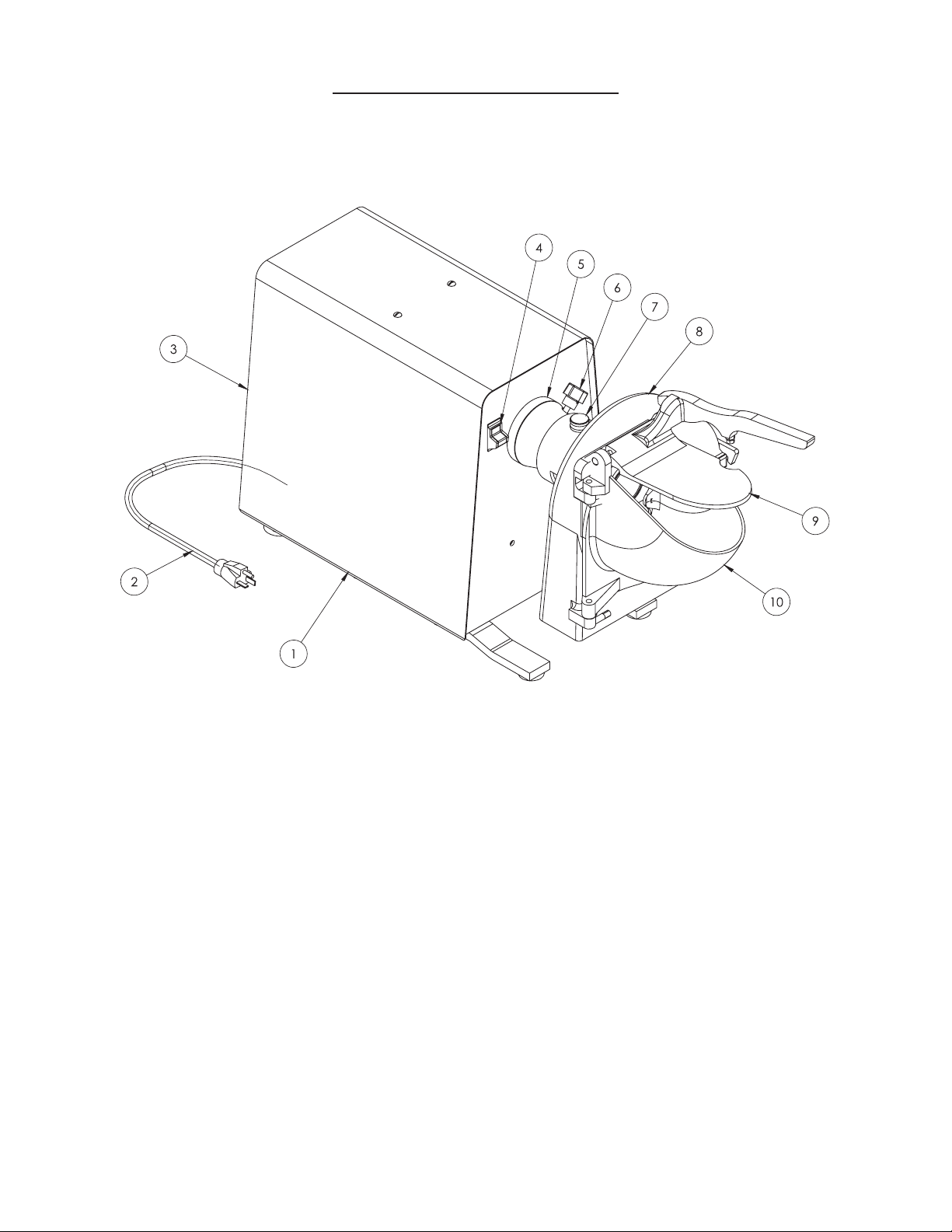
OVERALL VIEW OF THE VS2000
FIGURE 1
3. CIRCUIT BREAKER (ON BACK) 8. VS9/SV9H
(CANADA ONLY)
4. POWER SWITCH 9. FEED PLATE
5. POWER TAKE-OFF (PTO) 10. FEED HOPPER
PAGE 5
WERCSBMUHT.6TINUREWOP.1
NIPKCOLTFAHS.7DROCREWOP.2
Page 7

OPERATING INSTRUCTIONS
The VS2000 vegetable slicer/shredder should be set on a level, stable surface and in an area that is
convenient for the operator with sufficient clearance around the unit for safe operation.
Before installing the VS9 attachment, make sure the PTO adapter is properly installed on the drive
shaft.
Inset the VS9 in the PTO hub with a twisting motion and in an upright position and tighten the thumb
screw.
When processing foods, please observe the operating and safety instructions.
When processing is completed, place the on/off switch in the “OFF” position, remove the key and
disconnect the power supply cord.
Remove the attachment, disassemble, clean, dry and sanitize it before storing it in a dry environment.
Never hose rinse the machine.
PTO HUB
ALIGNMENT PIN
LOCATING HOLE
POWER TAKE-OFF HUB (PTO)
FIGURE 2
THUMB SCREW
COVER CAP
PTO ADAPTER
Page 6
Page 8

VEGETABLE PREPARATION ATTACHMENTS
VS9
STANDARD EQUIPMENT
Standard finish anodized aluminum housing with.
hinged feed chute door, latch and feed pusher.
SLICING
VS9 SLICING ATTACHMENT
FIGURE 3
Adjustable “S” knife assembly with hardened
stainless steel knife and #12 rear hub.
Typical usage:
LETTUCE RADISHES
CUCUMBERS PEPPERS
CARROTS CABBAGE
CELERY CHINESE VEGETABLES
POTATOES ONION
ZUCCHINI
ADJUSTABLE “S” KNIFE ASSEMBLY
FIGURE 4
Page 7
Page 9

VS9H
GRATING / SHREDDING
FIGURE 5
5/16 Shredder Plate
STANDARD EQUIPMENT
Die cast aluminum hub with stainless steel shaft and #12 rear hub and stainless locking pins.
Stainless steel 5/16 shredder plate.
CAUTION:
The VS2000 should not be used for any of the applications listed below. Failure to observe these
guidelines may result in damage to the VS2000 and will void the manufacture’s warranty.
Do not use the VS2000 to drive a meat grinder.
Do not use the VS2000 to process hard cheese with the grater plate or any other plate.
Do not use the VS2000 to process soft cheese.
OPTIONAL: SHREDDER AND GRATER PLATES AND TYPICAL USAGES
FOOD
PRODUCT
COLE SLAW
BREAD CRUMBS
CHEESE
SOFT CHEESE
FOR PIZZA
CARROTS FOR
COLORING
1/2”
SHREDDER
PLATE
000
•
5/16”
SHREDDER
PLATE
0
• •
•
Hub and Shaft Assembly
3/16”
SHREDDER
PLATE
3
SHREDDER
PLATE
•
• •
3/32”
7
UNIVERSAL
GRATER
PLATE
14
CHEESE FOR
TACOS
HARD CHEESE
•
•
Page 8
Page 10

PLATE UNITS - ASSEMBLYAND USE
CAUTION: Wear hand protection when working with these units.
THE ADJUSTABLE SLICER PLATE ASSEMBLY
To assemble the slicer plate, see Figure 6. When assembled, the plate can be adjusted to slice product
to different thicknesses by turning the adjusting nut as shown in figure 6.
PROPER ASSEMBLY OF THE SLICER PLATE ASSEMBLY
FIGURE 6
To tighten
Thrust bearing
Adjusting nut
To vary slice thickness
CAUTION: The thrust bearing must be securely tightened before the slicer plate assembly is loaded
into the housing. Failure to tighten the thrust bearing will damage the VS9 and the
VS2000 power unit.
NOTE: The thrust bearing requires a left hand twist to tighten.
WARNING: Adjustments for thickness must never be attempted while the VS2000 is under power or
severe personnel injury can occur.
Page 9
Page 11

THE GRATER, SHREDDER AND JULIENNE PLATE ASSEMBLY
To fit the plate of your choice to the hub and shaft, line up the key hole slots on the plate with the
locating pins on the hub, slip the plate over the pins and secure it by turning the plate in a clockwise
direction until it shoulders up firmly on the pins. This can be most safely accomplished by placing the
plate face down on a butcher’s block and turning the hub into position from above.
PLATE INSTALLATION
FIGURE 7
Turn plate clockwise
to lock
Keyhole Slot
Pin
Hub
Make sure that the thrust bearing is properly positioned on the shaft. Make sure the set screw on the
thrust bearing is tightened securely. A loose thrust bearing will allow clatter and damage the VS9.
NOTE: Do not remove the thrust bearing for cleaning.
Page 10
Page 12

LOADING PLATE UNITS INTO THE VS9 HOUSING
With the VS9 resting on a stable working surface, unlatch the front housing and swing it toward you.
Lift the assembled plate unit and insert it into the rear housing. Lift the shaft lock pin and seat the plate
unit with a gentle twist. Make sure that the thrust bearing on the shaft is fully inserted into the rear
housing and that the square milled end on the shaft has cleared the rear housing hub. Release the shaft
lock pin and close and securely latch the front housing.
The VS9 is now ready to mount to the power source equipment.
PROPERLY LOADED VS9/VS9H
FIGURE 8
Plate positioned far enough
back to prevent contact with
feed plate
Shaftlockpin
properly seated
Housing securely latched
Square milled
shaft end
Lock pin properly
engaging thrust bearing
Page 11
Page 13

PROCESSING PRODUCT
Before processing product, please review the plate usage chart on page 8, and please note that the feed
plate is equipped with an adjusting screw and jam nut. This assembly should be adjusted until there is no
chance of the feed plate coming in contact with the cutting surfaces. If the feed plate comes in contact
with the rotating cutting surfaces, both components will be damaged.
TO PROCESS PRODUCT:
Connect the VS2000 electrical power supply cord, and turn the unit on.
Lift the feed plate to expose the processing plate unit and drop product into the feed hopper. Keep
hands and fingers out of the hopper. With the feed plate, gently push the product into the rotating plate
unit.
If you experience a problem in processing, shut the VS2000 power unit off and refer to the trouble
shooting guide on page 14.
DISMOUNTING AND DISASSEMBLY
FOR CLEANING AND MAINTENANCE
DISMOUNTING:
Make sure that the VS2000 is turned off and its electrical power supply cord is disconnected. Loosen
the thumb screw and slide the VS9 from the PTO hub. Set the VS9 on a stable working surface.
DISASSEMBLY:
To disassemble the VS9 for cleaning or maintenance.
Unlatch the front housing and swing it toward you.
Swing the feed plate all the way up and slip it off the front housing and set it aside.
Lift the front housing from the pivots and set it aside.
Remove the processing plate unit
To disassemble the processing plate units, follow the assembly instructions on page 4 and 5 in reverse
order.
Page 12
Page 14

CLEANING:
To avoid damaging the VS9’s highly polished finish, never put any VS9 component through a dishwashing machine. Wearing hand protection, wash all components by hand with a mild soap and water
solution. Use a long handled scrub brush on all plate units to avoid cutting fingers. Do not rest knives,
grater plates, or shredding plates on any surface that will mar. Do not remove thrust bearings from
julienne or shredder plate shafts. Dry component parts with a soft cloth.
For the best and most sanitary product, clean the VS9 immediately after use or before switching food
products.
Never hose down the VS2000 Vegetable Slicer/Shredder. Hosing down the VS2000 invites electrical
shock.
LUBRICATION INSTRUCTIONS
FIGURE 9
Univex recommends the use of Petrol-Gel for all your food preparation equipment. It may be
purchased at your local food equipment supply company, or purchased directly from Univex
Corporation (Part No.4400408)
After every cleaning apply a thin coating of sanitary petroleum jelly to all bearing surfaces. Do not use
vegetable oil. It becomes gummy. If adjusting nuts and screws become stiff to work with, apply a drop
of sanitary mineral oil.
PETROL-GEL
PETROL-GEL
MINERAL OIL
Page 13
Page 15

MECHANICS MAINTENANCE
Before preforming maintenance on the VS9, please review the safety precautions on page 3-4 and read
all assembly and reassembly instructions. Wear gloves when handling plate units.
Since the VS9 contains no internal power source, most problems can be immediately traced to
improper assembly, improper adjustment or worn parts. The trouble shooting guide below lists the most
common problems and corrective measures.
TROUBLE SHOOTING GUIDE
CAUTION: Review all safety notes and disconnect the electrical power supply
to the power source equipment before attempting corrective measures.
TROUBLE POSSIBLE CAUSE SOLUTION
1. VS2000 power unit is under
power but plate will not turn.
2. Knife or plate scraping front
housing.
3. Shredding plate loose or
rattling
4. Front housing will not shut
tightly.
5. Mounted VS9 unit rattles
when under power.
6. Feed plate scraping plates. 6.1 Feed plate out of
1.1 PTO adapter missing from
power take-off assembly.
2.1 Thrust bearing loose.
2.2 Lock pin not fully engaged.
3.1 Plate loose on hub pins.
3.2 Plate bent.
4.1 Latch set screw out of
adjustment.
5.1 Thumb screw or securing
mechanism missing or
loose.
adjustment.
1.1 Replace PTO adapter.
2.1 Tighten thrust bearing.
2.2 Make sure lock pin is
properly engaged.
3.1 Inspect Shredder plate
assembly to assure plate is
shouldered firmly on pins.
3.2 Replace plate.
4.1 Adjust set screw at rear of
latch.
5.1 Tighten or replace.
6.1 Adjust feed plate with
adjusting screw.
Page 14
Page 16

Warranty
The Univex VS2000 Vegetable Slicer/Shredder
carries a one-year, on-site parts and labor warranty
against any defects in materials or workmanship.
The one-year period begins on the date of purchase
by the end user and remains in full effect provided
the unit is used properly and in accordance with our
instructions. Any work to be performed under this
warranty must be performed between the hours of
8:00 am and 5:00 pm local time, Monday through
Friday. Univex will not cover overtime charges of
any kind. Please call the Univex Warranty Service
Department at 800-258-6358 to report warranty
claims before arranging repair or attempting to
return the unit to Univex Corporation.
Damages incurred in transit or incurred because
of installation error, accident, alteration, or misuse
are not covered by this warranty. Transit damages
should be reported to the carrier immediately.
Univex will not be liable for any consequential,
compensatory, incidental or special damages.
3 Old Rockingham Road, Salem, N.H. 03079-2140 Telephone -603-893-6191 Fax 1-603-893-1249
TOLL FREE ORDERING FAX 1-800-356-5614
 Loading...