

Page 1
INSTRUCTION
MANUAL
- /-
t
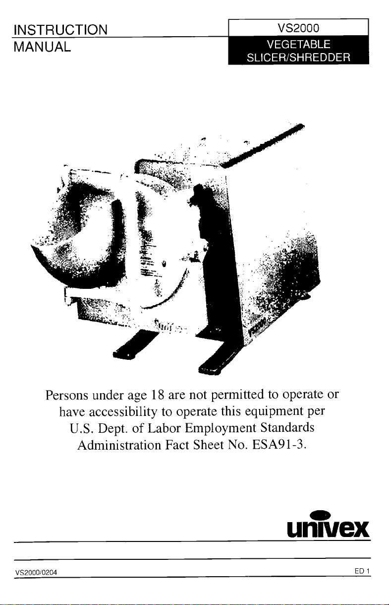
VEGETABLE
SLICER/SHREDDER
t
4
«
Persons under age 18 are not permitted to operate or
have accessibility to operate this equipment per
U.S. Dept. of Labor Employment Standards
Administration Fact Sheet No. ESA91-3.
univex
VS2000/0204
PDF compression, OCR, web optimization using a watermarked evaluation copy of CVISION PDFCompressor
ED i
Page 2
TABLE OF CONTENTS
VS2000
DESCRIPTION
TABLE OF CONTENTS
LIST OF DIAGRAMS
LIST OF ILLUSTRATIONS
INTRODUCTION
SAFETY
INSPECTION
OPERATOR INSTRUCTIONS
PLATE ASSEMBLY
SHREDDER PLATE ASSEMBLY
LOADING PLATE UNITS INTO VS9 HOUSING
MOUNTING INSTRUCTIONS
PROCESSING PRODUCT
DISMOUNTING AND DISASSEMBLY FOR CLEANING
LUBRICATION
PLATES USAGE
MECHANIC'S MAINTENANCE
TROUBLE SHOOTING GUIDE
REPLACEMENT PARTS AND ASSEMBLIES
DIAGRAMS
DIAGRAMS
DIAGRAM i
DIAGRAM 2
DIAGRAM 3
DIAGRAM 4
DIAGRAM 5
SLOT AND PIN ALIGNMENT
PROPERLY LOADED VS9/VS9H
TYPICAL POWER TAKE-OFF HUB
MOUNTING ANGLE
PROPER ASSEMBLY OF THE SLICER PLATE
PAGE
2
2
3
3-6
4
4
5
6
6
6
7
8
8
9
10-13
PAGE
3
4
5
5
9
LIST OF ILLUSTRATIONS
ILLUSTRATION
FIGURE i
FIGURE 2
FIGURE 3
FIGURE 4
POWER UNIT
VS9/VS9H HOUSING ASSEMBLY
KNIFE AND SHAFT ASSEMBLY
SHREDDER ASSEMBLY
Page 1
PAGE
10 11
12
13
13
PDF compression, OCR, web optimization using a watermarked evaluation copy of CVISION PDFCompressor
Page 3
VS2000
UN1VEX VS2000 HIGH VOLUME VEGETABLE SLICER/SHREDDER
INSTRUCTION MANUAL
The UNIVEX VS2000 HIGH VOLUME VEGETABLE SLICER/SHREDDER is a I HP
portable electric unit consisting of a poiy "V" belt assembly with a No. 12 drive hub operating at 700
rpm. It is designed to support and power the UNI VEX VS9 Vegetable slicer, and the VS9H Shredder
and Grater food processing attachments.
This manual contains instructions for the inspection, installation, safe operation, care, and maintenance
of the VS2000 Vegetable Slicer/Shredder.
instructions are included. A trouble shooting guide is provided. A complete replacement parts list with
Disassembly, repair, replacement, and reassembly
identifying figure diagrams is included to aid in identification and ordering of replacement parts.
Please review this manual carefully - particularly all safety precautions - before trying to put the
INTRODUCTION
VS2000 into service.
INSPECTION
The VS2000 drive assembly has been inspected and tested at the factory; however, it should be
externally inspected and electrically checked prior to use. The electrical data listed on the nameplate
should be the same as the user's electrical supply. Any damage should be reported to the carrier
immediately, and any shortage or deviation of parts to UNIVEX Corp.
SAFETY
The user should read and understand the V52000 and the attachment instructions prior to operation.
First time operators should be properly trained in safety precautions and in the proper use and servicing
of this equìpment and attachments.
Switch the power "OFF" and disconnect the electrical supply before mounting or disengaging an
attachment, or for cleaning and servicing the equipment.
Before, connecting unit to power source it should also be in the "OFF" position.
- Never insert hands Into the hopper.
- Never Insert any utensil Into the hopper.
Note that the front housing of the VS9 has a feed hopper [Fig. 2 (2)]. It is also equipped with a
feed plate [Fig. 2 (8)]. Food tobe processed must always be fed to cutting surfaces by way of the
hopper, and compressed against cutting surfaces with the feed plate. Never try to feed product to
cuttìng surfaces with your hands or any other way!
If during operation of a product jam occurs, immediately turn off and disconnect the electrical
supply to the power source equipment. Make sure rotation has stopped. Unlatch the VS9's front
housing, swing it toward you, and then clear the obstruction. Do not try to clear obstructions
while the V59 is under power, and again, never insert fingers or utensìls into the hopper!
Wear protective gloves whenever handling the VS9's knives, cutting plates, or cutting assemblies.
They are very sharp and can cut you. For safety, wash knives and cutting plates with a long
handled scrub brush.
When assembling or disassembling the VS9, make sure it rests on a stable working surface.
Never rest knives, cutting plates, or cutting assemblies on surfaces that could be marred.
Before assembling the VS9 and mounting it to power source equipment, make sure that a
comfortable working clearance has been provided around the machinery. Always install the
machinery where it will save the operator steps.
Before assembling the VS9 and mounting ìt to power source equipment, or dismounting the VS9
after use, disconnect or lockout the electrical supply to the power source equipment. This will
prevent any chance of accidental startup.
Page 2
PDF compression, OCR, web optimization using a watermarked evaluation copy of CVISION PDFCompressor
Page 4
VS2000
Before mounting the VS9 to power source equipment, make sure the front housing [Fig. 2 (8)] is
securely latched to the rear housing [Fig. 2 (9), (10), (11)].
The thumb screw [Fig. 1(22)] should be firmly snugged immediately after mounting the VS9 to
secure the VS9 in place. Do not operate the VS9 if there is no
power takeoff hub.
Never hose down a VS9 mounted to power source equipment. Hosing down a mounted VS9
.
invites electrical shock.
securing device present on the
CIRCUIT BREAKER.
Ef the circuit breaker HAS TRIPPED, turn the power switch to "OFF," and disconnect the electrical
supply, determine and then correct the fault before resetting. To prevent unauthorized use, remove
;witch key.
Be sure the attachment is properly cleaned, assembled, and installed, tighten thumb screw
connecting to power source. Do not attempt to service the drive assembly. Please contact Univex Corp.
the
before
for the number of the nearest authorized service agent in your area.
OPERATION INSTRUCTIONS
The VS2000 should be setup in an area that is convenient for operation, and has
for safety. Before installing the VS9 attachment, make sure the PTO adapter [Fig. 1 (24)]
installed on the drive shaft. The vegetable slicer should be attached with a twisting motion
upright position. Make sure to tighten the thumb screw. When processing foods please observe
zperating and safety instructions. When processing is completed, turn power to "OFF" and disconnect
power source. Remove the attachment, disassemble, clean, dry and
dry environment.
sanitize before storing in a clean,
sufficient clearance
is properly
and in an
CAUTION
The VS2000 should not be used for any of the applications listed below. Failure to observe
these
guidelines may result in damage to VS2000 and will void the manufacturer's warranty.
Do not use the VS2000 to drive a meat grinder accessory.
Do not use the VS2000 to process hard cheese with the grater plate or any other plate.
Do not use the VS2000 to process soft cheese
PLATE ASSEMBLY
CAUTION: Again, wear hand protection when workìng with these units.
ADJUSTABLE SLICER PLATE ASSEMBLY [Figure 3J
To assemble the slicer plate, see Figure 3 and Diagram 5 component assembly order and
The plate, when assembled, can be adjusted to slice product to different thickness by
fit as shown.
turning the
"adjusting nut" per the directions accompanying Diagram 5.
WARNING:
;evere personal injury can occur. See safety precautions -
Adjustments for thickness must never be attempted while the VS9 is under power or
Paragraph 2.
SHREDDER PLATE ASSEMBLY [Figure 4J
To fit the plate of your choice to the hub and shaft [Figure 4], line up the key hole
with the locating pins on the hub as shown below. Slip the plate over the pins and secure
the plate in a clockwise direction until it shoulders up firmly on the pins. This can be
by resting the plate face down on a butcher's block and turning the hub home from
Page 3
slots on the plate
it by turning
done most safely
above.
PDF compression, OCR, web optimization using a watermarked evaluation copy of CVISION PDFCompressor
Page 5
SLOT AND PIN ALIGNMENT
PIA1
TURN CLOCKWISE
TO LOCK
t,
a
)v
e'
t, I
vi
KEYHOLE
SLOTS
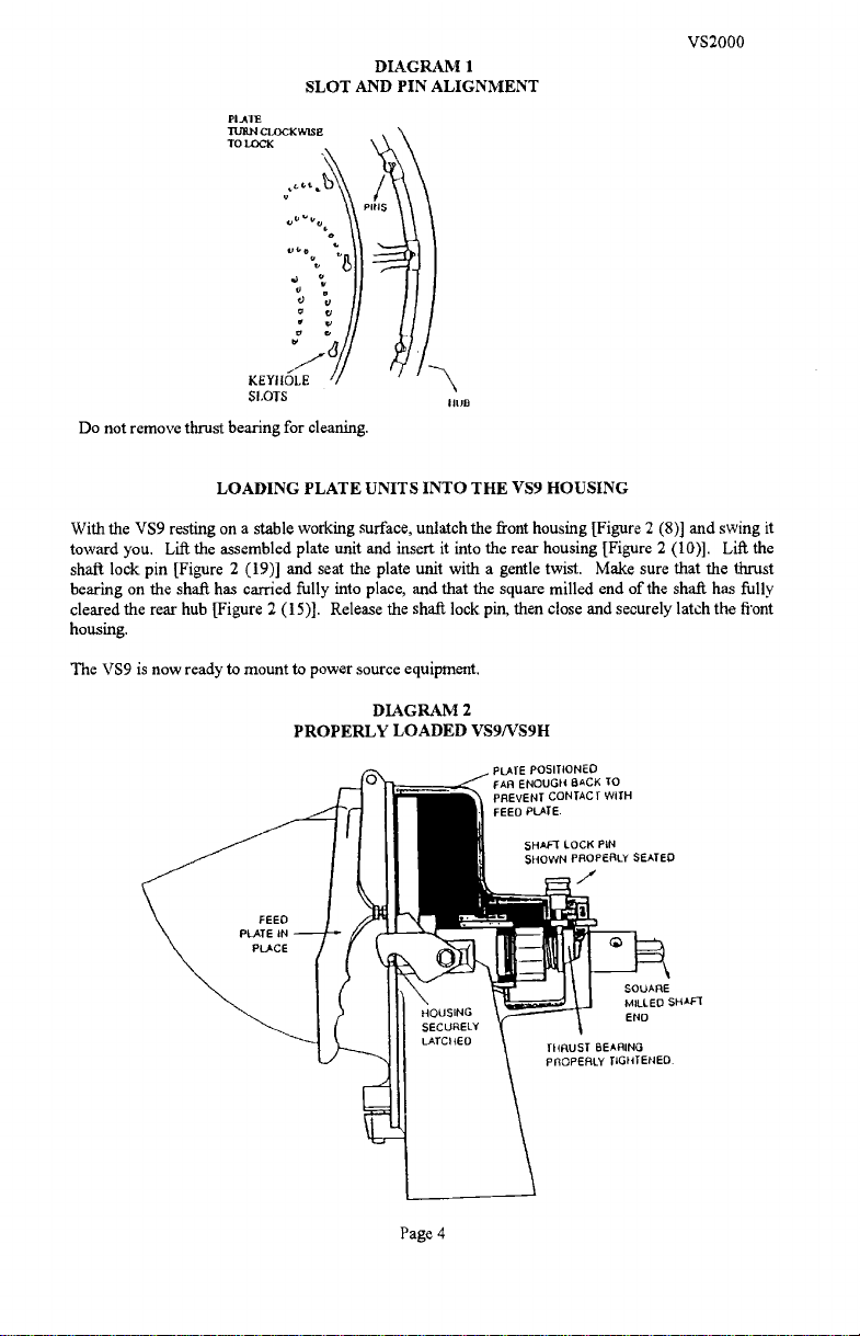
Do not remove thrust bearing for cleaning.
LOADING PLATE UNITS INTO THE VS9 HOUSING
VS2000
DIAGRAM i
I
IItJB
With the VS9 resting on a stable working surface, unlatch the front housing [Figure 2 (8)] and swing it
toward you. Lift the assembled plate unit and insert it into the rear housing [Figure 2 (10)].
Lift the
shaft lock pin [Figure 2 (19)] and seat the plate unit with a gentle twist. Make sure that the thrust
bearing on the shafi has carried fully into place, and that the square milled end of the shaft has fully
cleared the rear hub [Figure 2 (15)]. Release the shaft lock pin, then close and securely latch the front
housing.
The VS9 is now ready to mount to power source equipment.
DIAGRAM 2
PROPERLY LOADED VS9/VS9H
PLATE POSITIONED
FAA ENOUGH BACK To
PREVENT CONTACT WITH
FEEO PLATE.
SHAFT LOCK PIN
SHOWN PROPERLY SEATED.
7
SQUARE
MILLED SHAFt
ENO
tHRUST BEARING
PROPERLY TIGHTENED.
Page 4
PDF compression, OCR, web optimization using a watermarked evaluation copy of CVISION PDFCompressor
Page 6

VS2000
MOUNTING THE VS9 TO POWER SOURCE
Again, before mounting the VS9, make sure that the power source equipment is turned off and its
electrical supply disconnected or locked out.
TYPICAL POWER TAKEOFF HUB
DIAGRAM 3
PTO
ALK3NMEI4T
PN LOCATiNG
HOLE
THUMB
SCREW
PTO
ADAPTOR
COVER CAP
Remove the chrome cover cap from the power takeoff hub. Carefully lift the VS9 and insert the square
milled shaft end into the hub intake port (See diagram above), while holding the VS9 at the angle
pictured below.
Slide the VS9 forward until the square milled shaft end firmly seats in the PTO adapter [Diagram 3].
Gently twist the VS9 to a fully upright position, slide locating pin [Figure 2 (17)] into PTO locating
hole and snug the thumb screw [Diagram 3 ].
locating pin. The VS9 is now ready to process product.
MOUNTING ANGLE
(NOT OPERATING ANGLE)
NOTE: Only the #12 tapered hub is fitted with a
DIAGRAM 4
Page 5
PDF compression, OCR, web optimization using a watermarked evaluation copy of CVISION PDFCompressor
Page 7

PROCESSING PRODUCT
VS2000
Before processing product, please review the plate usage chart on Page 8, and please note that the feed
plate [Figure 2 (2)] is equipped with an adjusting nut and screw [Figure 2 (6-7)].
should be adjusted until there is no chance of the feed plate being compressed against cutting surfaces.
If the feed plate meets a rotating cutting surface, both components will be damaged.
This assembly
TO PROCESS:
Reconnect the electrical supply to the power source equipment, turn the VS2000, on.
Lift the feed plate to expose the plate unit, and drop product into the feed hopper. Keep hands clear.
With your hand holding the feed plate grip, gently compress product against the rotating plate unit.
If you experience problems in processing, shut down the power source equipment and refer to the
Trouble Shooting Guide on Page 9, and the safety precautions paragraph.
DISMOUNTING AND DISASSEMBLY
FOR CLEANING AND MAINTENANCE
DISMOUNTING
To dismount the VS9, simply follow the mounting instructions on Page 5 in reverse order. Set the VS9
on a stable working surface.
DISASSEMBLY
To disassemble the VS9 for cleaning or maintenance:
Unlatch the front housing and swing it toward you.
Lift the feed plate up and urge it to the left until it pivots off the front housing and set it aside.
Lift the front housing from its pivot holes and set it aside.
To disassemble the plate units, follow the assembly instructions on Pages 4-6 in reverse order.
Set the components aside.
CLEANING
To avoid
damaging the VS9's highly polished fmìsh, never put any VS9 component through a
dishwashing machine. Wearing hand protection, wash all components by hand with a mild soap and
water solution. Use a long handled scrub brush on all plate units to avoid finger cuts. Again, do not
rest knives or shredding plates on any surface which will mar. Do not remove thrust bearings from
Shredder plate shafts. Dry component parts with a soft dry rag.
For the best and most sanitary product, clean the VS9 immediately after use of before switching food
products.
Page 6
PDF compression, OCR, web optimization using a watermarked evaluation copy of CVISION PDFCompressor
Page 8

VS2000
LUBRICATION ll"STRUCTIONS
Enclosed is a sample tube of Petro-Gel which we recommend you use in all your food preparation
equipment.
It may be purchased at your local food equipment supply company, or purchased directly from: (Part
No. 4400408)
Univex Corporation
3 Old Rockingham Road
Salem, NH 03079
l-800-258-6358
LUBRICATION
After every cleaning, apply a thin coating of sterile petroleum jelly to all bearing surfaces. Do not use
vegetable oil.
of sterile mineral oil.
PDF compression, OCR, web optimization using a watermarked evaluation copy of CVISION PDFCompressor
It becomes gummy. If adjusting nuts and screw become stiff to work with, apply a drop
Page 7
Page 9

VS2000
PLATE USAGE
STANDARD EQUIPMENT Satin finish
Aluninum Housing with hinged chute door,
latch and feed pusher, NO. 12 rear hub and
locking pin.
Slicing adjustable "S" knife assembly with stainless
Steel knife. Typical usage
LETTUCE
CUCUMBERS
CARROTS
CELERY
Shredding assembly, with 5/16 Shredder Plate
RADISHES
CABBAGE
PEPPERS
POTATOES
CHINESE VEGETABLES
ONION
ZUCCHINI
CAUTION
The VS2000 should not be used for any of the applications listed below. Failure to observe these
guidelines may result in damage to VS2000 and will void the manufàcturer's warranty.
Do not use the VS2000 to drive a meat grinder accessory.
Do not use the VS2000 to process hard cheese with the grater plate or any other plate,
Do not use the VS2000 to process soft cheese
OPTIONAL: SHREDDER PLATES AND TYPICAL USAGE
FOOD
PRODUCT
1/2"
SHREDDER
PLATE
000
5/16"
SHREDDER
PLATE
0
3/16"
SHREDDER
PLATE
3
3/32"
SHREDDER
PLATE
7
COLESLAW .
BREAD CRUMBS
POTATOES
. .
CARROTS FOR COLORING
MECHANICS MAINTENANCE
Before trying to maintenance the VS9, review the safety precautions paragraph carefully, and read all
assembly-disassembly instructions on Pages 2-6. Wear gloves when handling plate units.
Since the VS9 contains no internal power source, most problems can be immediately traced to improper
assembly, improper adjustment or worn parts. The Trouble Shooting Guide on Page 9 lists the most
common problems and corrective measures.
PDF compression, OCR, web optimization using a watermarked evaluation copy of CVISION PDFCompressor
Page 8
Page 10

REPLACEMENT PARTS AND ASSEMBLIES
VS2000
Replacement parts and assemblies are displayed in Figure 1 through 4. When ordering, always
Univex part numbers and item descriptions.
nomenclature.
Common hardware parts are identified in normal
TROUBLESHOOTING GUIDE
Caution: Review all safety notes and disconnect electricity
to power source equipment before attempting corrective measures.
TROUBLE
1. Power source equipment is
under power but plate will
notturn.
2. Knife or plate scraping front
housing.
3. Shredding plates loose or
rattling,
-
POSSIBLE CAUSE
PTO adapter
missing from
power takeoff assembly
Thrust bearing loose, or lock
pin not fully engaged.
Plate is loose on hub pins.
SOLUTION
Replace PTO adapter.
Tighten thrust bearing
immediately, make sure lock pin
is properly engaged.
Inspect shredder plate assembly
to
assure
plate
is
shouldered
firmly up on pins.
shredder plate to assure it is not
bent
4. Front housing will not shut
tightly.
5. Mounted VS9 unit rattles
when under power.
6. Feed plate scraping plates.
PROPER ASSEMBLY OF THE SLICER PLATE ASSEMBLY
Latch set screw out of
adjustment.
Thumb screw on power
takeoff assembly missing or
too loose.
Feed plate adjusting unit out
of adjustment.
DIAGRAM 5
Adjust set screw at rear of latch
[Figure 2 (12)].
Tighten or replace.
Back off feed plate adjusting nut.
include
Inspect
THflUST EEATIUIG
ADJUSTING NUT: 10 VA1Y SUCE 1I4ICTIESS
IOCI<ITIG PIN
PPOT'ETT(Y ENGAGING
n-must
BEAnI NG
CAUTION: The thrust bearing must be securely tightened before the slicer plate
into the housing. Failure to tighten will damage the VS9 and the
The thrust bearing requires a left hand twist to tighten.
Page 9
power source equipment. NOTE:
assembly is loaded
PDF compression, OCR, web optimization using a watermarked evaluation copy of CVISION PDFCompressor
Page 11

LTEM NO.
1
2
3
4
5
6
7
8
9
10
11
12
13
14
15
16
17
18
19
20
21
22
23
24
25
26
27
28
29
30
31
32
33
34
35
36
37
38
39
40
41
42
43
44
45
46
49
50
51
52
53
54
55
PART NO.
8700001
8700014
8700002
4400141
1200075
8700104
1030019
4400072
8800010
4400230
1200117
1200119
8700311
8700310
1200025H
4400005
8700035
8700034
8700019
4400045
8800012
1200440
8700024
1200012
4400414
8700026
4400415
1200411
1200413
4400416
8700032
4400398
1012042
8800100
8800 100-2
4400351
1031307E
1031309
4400417
1024010
1200060
4400065
1200442
7510094
1200039
1200077
4400410
8700106
1200076
VS2000 POWER UNIT Figure 1
DESCRIPTION
Housing
Foam, Rubber Strip
Cover, Housing
Nut, Kep 1/4-20
Washer, Steel Flat '/
RESERVED
RESERVED
Feet
Ball Bearing 6204LL
RESERVED
SetScrew5/16-18x3/8
Shaft,PTO
Key3/16 Square
Retaining Ring mt.
Retaining Ring Ext.
Pulley, Driven
Belt, Drive32OJlO
Screw, Hex HD 1/4-20 x 3/4
Lock washer 1/4
Switch, With Key
Key, Switch (Key only)
Knob Assembly, P T 0
Housing, P T 0
Adapter, PTO
RESERVED
Bolt, 10-32 x 1
Pulley, Drive
RESERVED
RESERVED
Screw, Phil HD 10-32 x 1/2
Washer, Flat 1/4
Spring, Compression
Sleeve (Long)
Screw, Hex HD 1/4-20 x 2
Screw, Hex HD 1/4-20 x 1 1/2
Sleeve (Short)
Spacer, Isolator
Cable Tie
Strain Relief
Cord, Electric 115V
Cord, Electric 220V
Label, Stop Unplug (Not Shown)
Motor, 1 HP, 1 15\230V, 60 HZ
Motor, 1 HP, 220V, 50 HZ
Sleeve, Spring
Label, Univex (Not Shown)
Nut, Hex 10-32
Lock washer, #10
Thuss Head
Screw, 10-32 X
Feet
'/2
Screw5/16-18x3/4
Lockwasher5/16
Nut8mmxl.25
Legs
Washer no. 10
Page 10
VS2000
QTY.
1
2
1
4
7
4
2
2
1
2
2
1
1
3
5
1
1
1
1
6
4
2
2
2
2
2
4
3
1
1
1
2
3
2
4
2
4
4
2
2
2
PDF compression, OCR, web optimization using a watermarked evaluation copy of CVISION PDFCompressor
Page 12

56
57
58
FOR CSA ONLY
ITEM NO.
40
47
48
8900019
4400210
4400352
PART NO.
8800100.1
4400249
4400227
VS2000 POWER UNIT
Figure 1 (Cont.)
Screw SFHD 6-32 X 3/8
Washer P.T.O.
Label, VS2000 (Not Shown)
DESCRIPTION
Cord, Electric 115V
Circuit Breaker
Label, Reset (Not Shown)
VS2000 POWER UNIT
V52000
2
i
QTY.
Page 11
PDF compression, OCR, web optimization using a watermarked evaluation copy of CVISION PDFCompressor
Page 13

VS9IVS9H HOUSING ASSEMBLY
FIGURE 2
VS2000
ELLUS. NO.
1. 4400028 PUSHER PIN. LEFT
2.
3.
4.
5.
6. 4400057 STOP NUT 1/4-20 1
7. 1200025H
8.
9.
10.
11.
12.
13.
14.
15.*
PART NO. DESCRIPTION
1000903 FEED PLATE
4400097 NYLON WASHER 1/2" O.D. X 1/8" X 3/8" ID.
4400029
PUSHER PIN - RIGHT 1
0090004 HINGE PINS 2
SCREW, Hex HD 1/4-20 x 3/4
1000902
FRONT HOUSING
4400400 DOWEL PIN 1/4" X 1" SS 1
1000901
1000806
4400193
1200377
0090000
1000918
REAR HOUSING
LATCH 1
SET SCREW 10-32 X 3/8"
WASHER, BEVEL 5/16" ID.
LATCH SCREW
#12 TAPERED HUB (STANDARD)
QTY.
1
1
1
1
1
1
0090005 UNI VEX REAR HUB (OPTIONAL)
16. 4400091 PAN HEAD SCREW 1/4-20 X 5/8"
17.
18. 4400184
19.
20. 1000914
21.
0090002 LOCATING PIN 5/16" X 1"
FULLDOGSETSCREW5/16"-24X1/2
1000811
1000923 PLASTIC BUTTON - FRONT COVER
SHAFT LOCK PIN (INCLUDES 4400180)
BRONZE BUSHING
6
1
1
1
1
1
When ordering, specify #12 tapered hub or Univex rear hub. The Univex rear hub does not have
accommodation for a locating pin (17), and will only fit older Univex manufactured power source
equipment.
Page 12
PDF compression, OCR, web optimization using a watermarked evaluation copy of CVISION PDFCompressor
Page 14

ILLUS. NO.
2.*
3*
4*
5*
KNIFE AND SHAFT ASSEMBLY
PART NO.
1000922
4400004
4400092
1000820
1000904
1000808
1000917
1000809
are for illustration only. They
DESCRIPTION
KNIFE
ROLL PIN 1/4' X 11/8"
DRIVE PIN
DRIVE SHAFT
PLATE ADJUSTING
NUT.ADJUST1JG
SPRING - NUT ADJUSTING
BEAIQJNG - THRUST
FIGURE 3
can only be purchased as Assembly No.
® () (i)
///
ç
4_'
VS2000
QTY.
1
1
1* Illus, 1 -5
1000912.
ILLUS. NO,
2.**
3*
4*
5*
6.*
7.
8.
9.
10.
11.
* Illus. 1, 4, 5, &
** Illustration 2
SHREDDER PLATE ASSEMBLY
PART NO.
1000116
1200036
1000973
4400116
1000975
1000115
1000907
1000908
1000909
1000910
6 are for illustration only. They
must be purchased with Illustration
DESCRIPTION
SHAFT
SET SCREW 5/16" -24 X 3/8"
THRUST BEARING
ROLLPIN3/l6"xl.1/2"
PLATE PINS
PLATE HOLDER
RESERVED
SHREDDER PLATE 3/32" DIA
SHREDDER PLATE 1/2" DIA
SHREDDER PLATF.
SHREDDER PLATE 5/16"
WITH OPTIONAL PLATES
FIGURE 4
" flTS
I1
can only be purchased as Assembly No.
3.
DIA.
QTY.
8
OPTIONAL
OPTIONAL
OPTIONAL
1000913.
,®
(D
(k
Page 13
PDF compression, OCR, web optimization using a watermarked evaluation copy of CVISION PDFCompressor
 Loading...