

Page 1

MECHANICS
MAINTENANCE
MANUAL
SRM60+/0699001 ED2
0011065
Page 2

SRM60+
TABLE OF CONTENTS
DESCRIPTION PAGE
TROUBLE SHOOTING GUIDE ......................................................................………….. 3
REMOVAL OF TOP COVER AND REAR ACCESS PANEL ............................………. 4
MECHANICS MAINTENANCE ......................................................................………….. 4-6
REPAIR INSTRUCTIONS ...........................................................................……………… 7- 12
REPLACEMENT PARTS, LISTS .................................................................…………….. 13 -24
ELECTRICAL CONNECTIONS AND ROTATION .........................................…………. 25
WIRING DIAGRAMS ..................................................................................……………… 26 -28
LIST OF ILLUSTRATIONS
ILLUSTRATION PAGE
FIGURE 1 OVERALL VIEW OF MIXER ..................................................……... 2
FIGURE 2 LUBRICATION INSTRUCTIONS ............................................…….. 6
FIGURE 3 GEAR BOX ..............................................................................………. 13
FIGURE 4 BEATER HEAD AND VERTICAL SHAFT ASSEMBLY ...........….. 14
FIGURE 5 POWER TAKE OFF ASSEMBLY .............................................…….. 15
FIGURE 6 INPUT ASSEMBLY .................................................................……… 16
FIGURE 7 BOWL LIFT ASSEMBLY ......................................................………. 17-18
FIGURE 8 SPEED CONTROL ASSEMBLY ............................................……… 19 -20
FIGURE 9 BOWL SUPPORT ASSEMBLY .................................................…… 21
FIGURE 10 HOUSING ASSEMBLY .........................................................………. 22 -23
FIGURE 11 DRIVE ASSEMBLY .................................................................…….. 24
FIGURE 12A WIRING DIAGRAM 208-240 V, 60HZ, 1PH,
FIGURE 12B WIRING DIAGRAM 208-240V, 60HZ, 3PH,
FIGURE 12C WIRING DIAGRAM 460V, 60HZ, 3PH, 380V, 50HZ, 3PH……….. 28
220-240V, 50HZ, 1PH, ........…………………………………………. 26
220V, 50HZ, 3PH, 200V, 50/60HZ, 3PH……………………………. 27
PAGE 1
Page 3
SRM60+
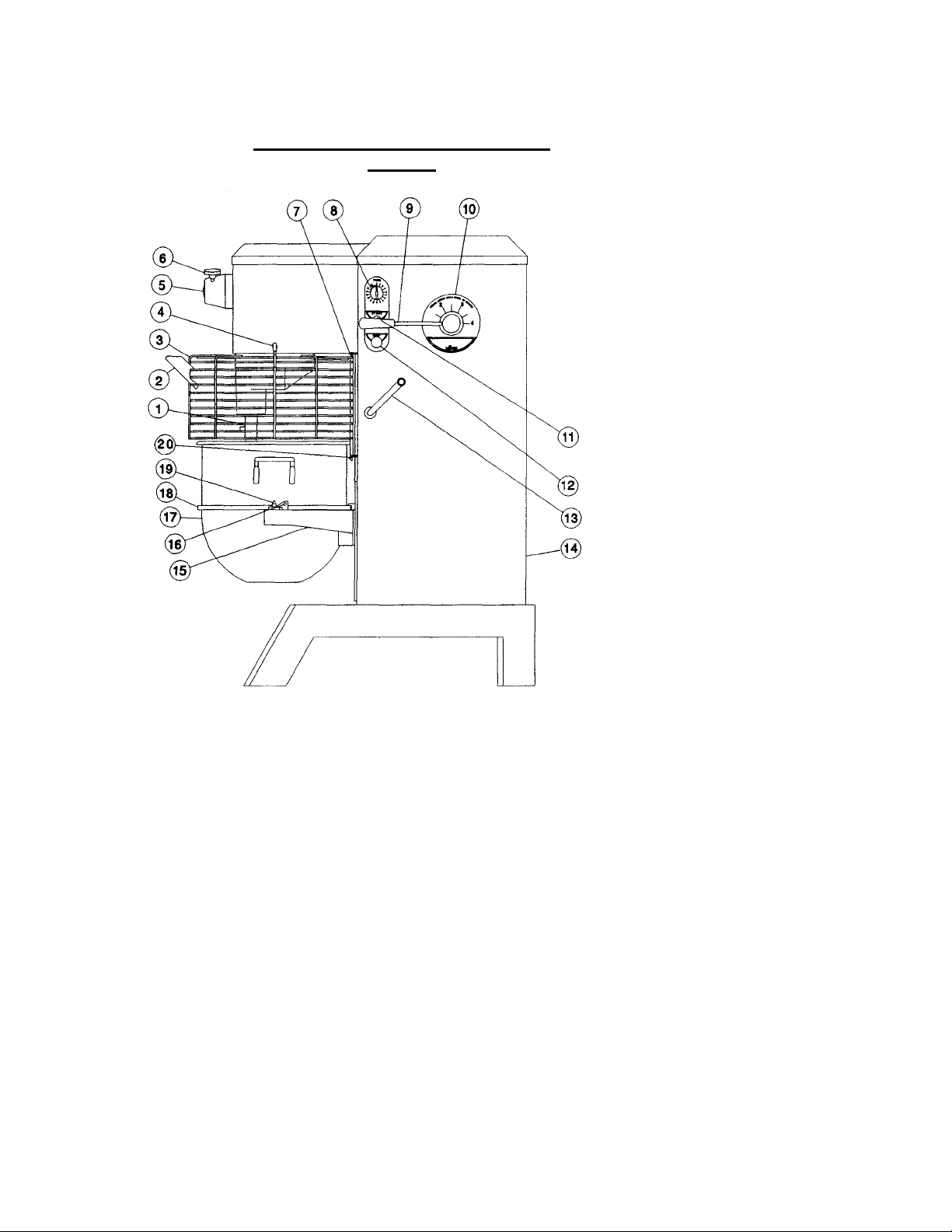
OVERALL VIEW OF FOOD MIXER
Figure 1
1. BEATER SHAFT
2. CHUTE
3. SAFETY RING ASSEMBLY
4. MAGNET
5. NO. 12 HUB
6. THUMB SCREW
7. UPPER MOUNTING BRACKET
8. TIMER
9. SPEED CONTROL LEVER
10. SPEED INDICATOR LABEL
11. START BUTTON
12. STOP BUTTON
13. BOWL LIFT HANDLE
14. REAR ACCESS PANEL
15. BOWL SUPPORT
16. BOWL CLAMP
17. BOWL
18. BOWL RIM
19. BOWL SUPPORT PIN
20. LOWER MOUNTING BRACKET
Page 2
Page 4

SRM60+ TROUBLESHOOTING GUIDE
1 Mixer will not
1.1 Timer not turned on.
1.1 Turn timer on.
2. Mixer runs but
2.1 Drive belt off of pulley.
2.1 Reinstall drive belt on motor
3. Stalling of
3.1 Mixer bowl is overloaded.
3.1 Readjust contents
of bowl per
4. Speeds not
4.1 Loose belt.
4.1 Tighten or replace.
5. Mixer ru
ns but
, 5.1 Bowl overloaded.
5.1 Reduce content of bowl.
6. At
tachments
6.1 Dented bowl.
6.1 remove dent or replace.
7. Attachments
7.1 Dented bowl.
7.1 remove dent or replace.
8. Excessive noise.
8.1 Gears need to be repacked
8.1 Locate source by inspection
TROUBLE POSSIBLE CAUSE REMEDY
operate. 1.2 Burned switch contacts. 1.2 Clean or replace.
1.3 Electrical service down. 1.3 Check electrical service.
Replace fuse or reset circuit
breaker as necessary.
1.4 Motor capacitor defective 1.4 Replace.
(1PHonly).
1.5 Burned out motor. 1.5 Remove, test, repair or
replace.
1.6 Magnetic starter tripped due 1.6 Wait several minutes and
to overload.
1.7 SAFETY RING not mounted 1.7 Install SAFETY RING.
and closed.
1.8 Bowl not raised. 1.8 Raise bowl completely.
push start button.
SRM60+
beater will not
turn.
2.2 Key or pin sheared on bevel 2.2 Locate by step inspection and
pinion, vertical shaft or beater
shaft.
2.3 Shifting with mixer not 2.3 With mixer running, slowly
running.
agitator during
mixing. 3.2 Speed is set too high for the 3.2 Shift speed lower till action
changing 4.2 Vari-speed pulley inoperative. 4.2 Remove, clean & lubricate or
properly.
keeps cutting out 5.2 Speed set too high for bowl 5.2 Reduce speed
and stops.
mix.
3.3 Loose belt. 3.3 Readjust pulley center
3.4 Contamination of belt with 3.4 Clean pulleys and replace
grease.
contents.
5.3 Service voltage is too low or 5.3 Check electrical voltage.
fluctuating.
pulley and adjust mount
center distance.
replace defective parts.
move shift lever fully forward
then backward in order to
re-engage belt.
Capacity Chart.
rotates smoothly.
distance to tighten belt.
belt.
replace
contact bottom of 6.2 Bowl height set too high. 6.2 Reset bowl height.
bowl.
contact side of 7.2 Insufficient clearance between 7.2 readjust bowl height.
bowl.
bottom of bowl and beater.
with grease, or oil level is
low.
8.2 Badly worn or frayed drive 8.2 Replace belt.
belt.
8.3 Attachments hitting bowl. 8.3 Inspect for cause. Ref. 6 & 7
8.4 Overloaded mixing bowl. 8.4 Readjust contents of bowl per
and repack with grease or top
off oil level.
Table of Mixing Capacities.
Page 3
Page 5

REMOVAL OF TOP COVER AND REAR ACCESS PANEL
SRM60+
a. The top cover (Fig. 10 [17]) must be removed in order to perform the
A mechanic should perform the following inspection and maintenance as required
depending on severity of use, but at least yearly.
1. CVT BELT DRIVE
maintenance operations. It is secured by a spring clip at its front end and a screw
at its rearward end. First, DISCONNECT THE ELECTRICAL POWER FOR
SAFETY. Then, remove the screw in the rear (Fig. 10 [20]), lift rear of cover,
push forward about 3 inches and lift cover off. Re-install in reverse procedure
using care to insure that the cover sits squarely and uniformly on the mixer
housing.
b. Remove rear access panel (Fig. 10 [27]) by removing eight screws and
washers (Fig. 10 [23, 24])
MECHANICS MAINTENANCE
a. Start mixer and shift speed control (Fig. 1 [9]) to the slowest speed (Low, 1).
Stop mixer.
WARNING: FOR SAFETY, DISCONNECT ELECTRICAL POWER. Place
tag or sign on electrical supply warning that MIXER IS BEING
WORKED ON; DO NOT TURN ON.
b. Remove rear access panel (Fig. 10 [22]) and top cover (Fig. 10 [17]) as
described above.
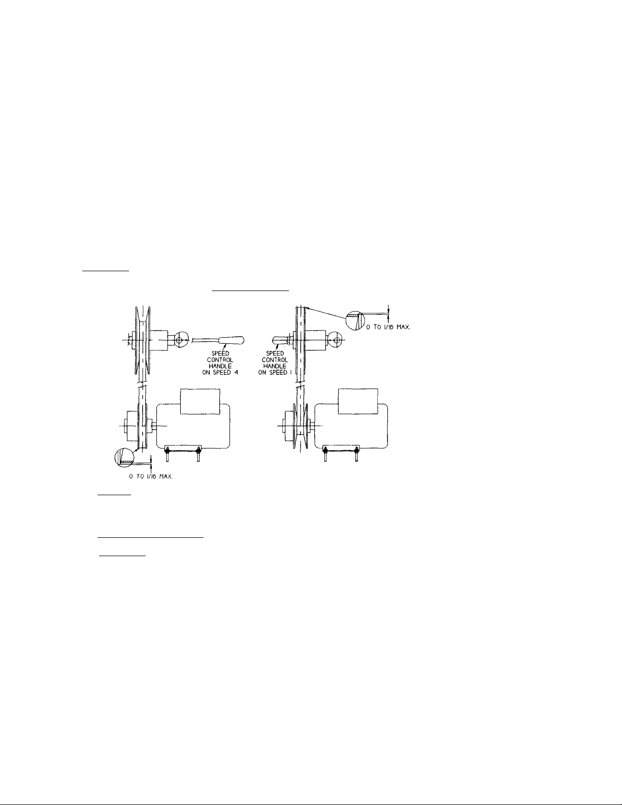
c. Inspect drive belt (Fig. 11 [2]) for proper adjustment. Outer surface of belt
should be approximately flush to 1/16" below the outer edges of the input pulley
flanges (Fig. 11 [5]) when mixer has been shut off in first speed (see Pg. 5). If
drive belt is excessively frayed or has a heavily glazed surface, replace it.
However, it is generally the best judgment to leave a drive belt in a machine if it
is performing well, even it if shows moderate wear. Inspect gripping surfaces of
drive belt for excessively glazed surfaces or contamination by grease or oil.
To replace belt, run mixer in 1st speed. Disconnect electrical supply. Shift
machine to 4th speed. Unwrap belt from top pulley. Slide belt between top
pulley nose and cam (Fig. 8 [8]). Remove belt from lower pulley.
WARNING: Lower pulley flanges are spring loaded. Keep fingers away while
removing belt.
The bowl must be lowered in order for the belt to clear the nose of the lower
pulley when removing belt. To install new belt wrap belt around lower pulley.
Pull belt into the spring loaded flanges. A pry bar will help separate the flanges.
Continue replacement in reverse order from belt removal. Adjustment of the belt
drive will most likely be required.
d. Readjustment of the drive belt, where a slight stretching or normal seating has
caused outer surface of the belt to exceed the acceptable limit of flush to 1/16"
below the input pulley flanges (see Pg. 5) is as follows:
Loosen kep nuts (Fig. 8 [12]) securing the bracket (Fig. 8 [15]) and holder(Fig. 8
[1]) to the housing. If the belt was riding outside the pulley flanges, tap the speed
control assembly lightly towards the rear of the mixer. If the belt was riding
more than 1/16" below the pulley flanges, tap the speed
Page 4
Page 6
control assembly towards the front of the machine (shifting to 2nd second speed will
help).
Note: The assembly must remain perpendicular to the mixer housing walls. Failure to do
so will result in the binding of the shaft (Fig. 8 [10]) in the bearing (Fig. 8 [21]).
Retighten the kep nuts and run mixer in 1st speed and check belt position. Repeat
procedure if necessary.
e. Once the upper pulley (Fig. 11 [5]) has been adjusted, the lower pulley must be checked.
Start mixer and shift to 4th speed. Turn mixer off and check position of belt. The belt
should be flush to 1/16" below outer edges of the pulley flanges. If adjustment is needed,
loosen kep nuts (Fig. 11 [14]) and raise or lower the motor using the kep nuts on the
under side of motor. Retighten top kep nuts and run mixer in 4th speed to check new belt
position.
Note: The motor must remain level with the mixer base (Fig. 10 [1]). If not, poor shifting
and belt life will result.
WARNING: FOR SAFETY, DISCONNECT ELECTRICAL POWER.
DRIVE BELT SETUP
SRM60+
2. MOTOR
Check motor (Fig. 11 [16]) for overheating and excessive noise. If defective, send to a local
electrical repair shop.
3. BOWL LIFT ADJUSTMENT
WARNING: FOR SAFETY, DISCONNECT ELECTRICAL POWER.
a. Check adjustment by placing a 60 quart bowl on the lowered bowl support, and place a
60 quart batter beater on the beater shaft (Fig. 1 [1]).
b. Raise bowl support to the upper position.
c. Check clearance between bottom of the bowl and the adjacent underside of the batter beater.
Clearance should be 3/16" ± 1/16".
Page 5
Page 7
d. If adjustment is required, loose jam nut (Fig. 7 [25]) and turn threaded bowl stop rod
(Fig.7 [24]) until the desired clearance is obtained, then tighten the jam nut.
4. DRIVE BELT REPLACEMENT (See CVT Belt Drive)
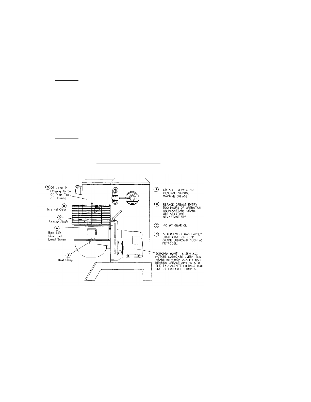
5. LUBRICATION
WARNING: FOR SAFETY, DISCONNECT ELECTRICAL POWER TO THE MIXER.
a. The lubrication instructions are listed in Figure 2.
b. Remove access panel (Fig. 10 [22]), top cover (Fig. 10 [17]) per page 4.
c. In order to service the gearbox, it will be necessary to further remove the gearbox cover
(Fig. 3 [2]). A thin blade putty knife will prove helpful in separating the silicone sealant
between this cover and the gearbox. Do not bend cover. Thoroughly remove all dried
sealant before applying new sealant when reinstalling the cover. Do not allow dried
sealant to enter gearbox. Silicone rubber sealant such as Dow Corning Silastic 732RTV or
Permatex Form-A-Gasket are recommended.
WARNING: NEVER WORK ON THE GEARBOX WITH THE MIXER
RUNNING.
d. Use care to avoid getting lubricant of any kind on the drive belt and pulleys as this would
seriously deteriorate the belt grip and mixer performance.
LUBRICATION INSTRUCTIONS
FIGURE 2
SRM60+
Page 6
Page 8

(Including Disassembly, Replacement and Reassembly)
REPAIR INSTRUCTIONS
A. GEARBOX (Fig. 3)
GEARBOX REMOVAL:
1. Run mixer and shift to first speed then turn off.
2. WARNING: FOR SAFETY, DISCONNECT ELECTRICAL SUPPLY.
3. Remove set screw (Fig. 3 [16]) and drain oil.
4. Remove rear access panel (Fig. 10 [22]), top cover (Fig. 10 [17]), detailed on page 4.
5. Remove drive belt per instructions (1) in Mechanic's Maintenance.
6. Remove speed control assembly (Fig. 8) See Speed
Control Disassembly.
7. Loosen two allen set screws (Fig. 11 [4]) that secure input pulley (Fig. 11 [5]) and
remove pulley completely from input shaft (Fig. 6 [12]).
8. Remove gearbox cover (Fig. 3 [2]). Remove remaining oil from gearbox.
9. WARNING - FOR SAFETY! The gearbox is very heavy, weighing
approximately 225 pounds and must, therefore, be supported safely before starting step
number (10). It is recommended that a portable hydraulic crane of sufficient capacity be
used. A chain may be attached to t he P.T.O. shaft (Fig. 5 [11]) at mid-length. Use care
not to rub or scrape the gears.
10. Remove four cap screws (Fig. 3 [11]) securing gearbox housing to mixer housing.
Remove gear box assembly and place on work bench.
11. Rotate gear train by hand and inspect for worn or chipped gears, bent shaft, worn
bearings and excessive backlash. Backlash measured at gear teeth exceeding 1/32" is
considered excessive. After trouble has been isolated, proceed to disassemble.
SRM60+
GEARBOX DISASSEMBLY:
1. Beater Head (Fig. 4)
a. Remove cap screw (Fig. 4 [21]) and remove beater head assy. If beater head does not
drop easily, use the two jacking screws (Fig. 4 [19]) to assist in removal. Do not pry
against outer rim of beater head housing (may cause breakage).
b. Remove top retaining ring [9], gear [II], bottom retaining ring [9], key [7], seal [10],
retaining ring [9], retaining ring [8], and press shaft [2] (at gear end) from housing
[1].
c. Press bearings [4 & 6] along with spacer [5] from housing [1].
Page 7
Page 9

2. Power Take Off (Fig. 5)
a. Remove three cap screws (Fig. 5 [5]) and washers [6] holding P.T.O.
housing [3] to gearbox housing (Fig. 3 [1]).
b. Remove retaining ring [8] from helical gear end of P.T.O. shaft [11].
Remove gear [14] and key [15].
c. Using two cap screws as Jacking screws (Fig. 5 [5]) in the tapped
holes of gearbox housing (Fig. 3 [1]), dislodge and remove the P.T.O.
assembly from the gearbox housing.
d. Remove retaining ring [8] and slide bevel gear [13] away from P.T.O.
housing [3].
e. Remove internal retaining ring [9], P.T.O. adaptor [2] and press shaft,
bearing, and gear assembly from P.T.O. housing [3].
f. Remove four retaining rings [8] and key [15] from P.T.O. shaft [II], and
press ball bearings [10] and P.T.O. bevel gear [13] off P.T.O. shaft [11].
g. Remove P.T.O. oil seal [7] from P.T.O. housing [3] and discard.
3. Input (Fig. 6)
a. Remove four cap screws (Fig. 6 [11] from flange of input housing [9].
b. Thread two of the cap screws [11] into the two threaded jacking holes in
the flange [9]. Turn these two screws in evenly until the input housing is
pushed free of the gear box housing.
SRM60+
c. Remove sleeve [14] and proceed to remove input shaft [12] out of input
housing [9] by pressing from opposite the gear end of the shaft.
d. Remove retaining ring [5] at gear end of the shaft, and press off
bearing [7].
e. Remove rubber seal [4] from housing or shaft. Seal must be replaced.
f. Remove retaining rings [6] and bearing [7] from housing.
4. Vertical Shaft (Fig. 4)
a. Remove beater head as covered in Gearbox Disassembly (1) a-c. b.
Remove P.T.O. assembly as covered in Gearbox Disassembly (2) a-g.
c. Remove key (Fig. 4 [18]) and retaining ring [9] from vertical shaft [13].
d. Drive vertical shaft downward into the gearbox. A brass drift will be
necessary to drive shaft completely free from the gear box. Lift bevel gear
[12] and key [14] from gear box.
e. Insert drift through top of bearing [15] in gearbox and drive seal [16] out
bottom of bore.
Page 8
Page 10

f. Reach up into bore from bottom opening with snap ring pliers and
remove retaining ring [8] from bore.
g. Carefully drive upper bearing [15] out bottom of bore.
h. Press bearing [17] from shaft [13].
GEARBOX ASSEMBLY
SRM60+
1. Clean all components (except bearings) with safety approved cleaning
2. If shafts have become slightly scored during the disassembly process, it is
3. Always fit new rubber seals when rebuilding the gearbox. Use special
4. Reassembly should be carried out in reverse of the disassembly procedure
solvent. Inspect components for defects and replace those found to be
defective.
NOTE: If planetary pinion gear (Fig. 4 [11]) requires replacement, it is
likely that the planetary gear (Fig. 3 [20]) requires replacement also.
necessary to polish the shafts with fine machinist's crocus cloth. An
especially smooth finish is necessary in the working seal area of the shafts.
Use care to avoid excessive removal of shaft surface or proper fit of
components will be lost.
attention in examining the end of the shafts over which the seals will be
pushed. The slightest burring or scoring will abrade or cut the delicate seal
lips. A light polish of the shaft ends with crocus cloth is recommended.
see exception below. Successful reassembly is very dependent on the
cleanliness of all surfaces, particularly the bores of housings, gears, and
bearings, as well as the outer surface of shafts. It is good to recheck each
component for cleanliness as it is picked up for reassembly.
THE ASSEMBLY OF THE INPUT IS AS FELLOWS.
a Install retaining ring (Fig. 6 [6]) into housing [9], press in bearing [7] and
install remaining retaining ring [6].
b. Slide seal [4], with spring facing gear, along length of shaft opposite the
gear (be careful when sliding seal over retaining ring groove not to damage
the seal). Install bearing [7] and retaining rings [5] onto gear end of shaft.
c Press shaft into bearing [7] mounted in housing [9] until the retaining ring
[5] seats against the bearing.
d Press seal OD flush with end of housing.
5. Transmission should be progressively checked for smooth operation while
on the workbench by hand turning each assembly as it is installed.
6. Lubrication of the gear box should be done following its installation on the
mixer. The helical and bevel housing compartments are filled to a level 6"
(10 qts.) from the top edge of the gear box with SAE 140 gear oil.
Page 9
Page 11

B. BOWL LIFT & SLIDE (Fig. 7)
BOWL LIFT & SLIDE DISASSEMBLY & REMOVAL
CAUTION: FOR SAFETY, DISCONNECT ELECTRICAL SUPPLY.
1. Remove top cover and rear access panel as stated on page 4.
2. Remove drive belt from motor pulley as stated in Mechanics Maintenance Section 1 (c).
3. Remove drive assembly (Fig. 11) from mixer housing as follows:
a. Remove the top 4 kep nuts (Fig. 11 [14]) that secure motor assembly to mixer base.
b. Remove motor electrical leads (Fig. 11 [13]) from magnetic starter (Fig. 10 [26]).
Remove motor ground lead from stud.
c. Lift motor assembly from mixer housing.
CAUTION: Drive assembly can weight in excess of 100 Ibs. depending on type of
motor. Use mechanical lift assistance.
4. Remove bowl from bowl support.
5. Remove two screws (Fig. 9 [10]).
6. Remove 4 screws (Fig. 7 [30]).
CAUTION: Someone should be holding bowl support (Fig. 9 [1]) while the screws are
being removed, so that it does not fall and get damaged. Remove slide cover (Fig. 9 [8]).
SRM60+
7. Loosen set screws (Fig. 7 [41]) and Fig. 7 [8]).
8. Withdraw handle assy. (Fig. 7 [36]) from the outside of mixer housing. Collect gear [9],
key [37], washers [4 & 42] and collar [40].
9. Remove 8 nuts (Fig. 7 [29]) and pull slide/frame assembly from studs and remove from
mixer housing.
CAUTION: Assembly is heavy.
10. Remove 2 hex head cap screws (Fig. 7 [15]). This allows for removal of yoke (Fig. 7 [7]).
11. Drive roll pin (Fig. 7 [11]) from miter gear (Fig. 7 [12]). Remove miter gear and thrust
washer (Fig. 7 [4]) from lead screw (Fig. 7 [10]).
12. Press lead screw (Fig. 7 [10]) through hole in frame [1].
13. Loosen set screws (2). Remove collar [3] and thrust washer (Fig. 7 [4]) by pulling them
from lead screw.
14. Unscrew lead screw from floating nut (Fig. 7 [26]) and remove.
15. Remove 4 screws (Fig. 7 [15]) and remove gibbs (Fig. 7 [27]). The slide may now be
removed from the frame.
Page 10
Page 12

SRM60+
NOTE: Save any shim strips that may have been used between the frame and the
gibbs. It is recommended that the location be marked at this time with a pencil to
facilitate reinstallation.
BOWL LIFT & SLIDE. REASSEMBLY & INSTALLATION (Fig. 7)
1. Grease sliding surfaces of slide & frame. See Lubrication page 6.
2. Keeping shims in place (if any), position slide in frame as shown in Fig. 7.
3. Secure slide (Fig. 7 [32]) in frame [1] by bolting gibbs [27] to frame with four hex
head cap screws [15]. Check to insure that slide moves freely in frame. If not, remove
gibbs and shim where needed.
4. Screw lead screw [10] into floating nut [26] and push slide to bottom of frame so that
the lead screw does not protrude through hole in frame.
5. Place the collar [3] and then thrust washer [4] over top of lead screw [10]. Push slide
and lead screw up -so that the lead screw protrudes through hole in frame.
6. Place thrust washer [4] and then miter gear [12] on top of lead screw [10]. Drive roll
pin [11] through miter gear [12] and into lead screw [10].
7. Push slide & lead screw down as far as possible. Slide collar [3] and thrust washer [4]
up against frame and tighten set screws [2] in collar against corresponding flats on
lead screw [10].
8. Check DU bearings in yoke for burrs (Fig. 7 [6]). Install yoke [7] to frame [1] (do not
tighten bolts).
9. Lift assembly into mixer housing. Place assembly on 8 weld studs. Tighten
assembly to mixer housing using washers and kep nuts.
10. Insert bowl lift lever assembly (Fig. 7 [33-36,38,39]) through hole in mixer housing.
Slide collar [40] and thrust washer [42] over end of lever. Insert lever through yoke
while holding the thrust washer [4] and miter gear [9] in position. Continue to slide
lever through until miter gear seats against shoulder on the lever shaft. Align
keyways of miter gear and lever, insert key [37]. Tighten set screw [8]. Squeezing
miter gear [9] and collar [40], tighten set screw [41].
11. With yoke bolts [15] lightly tightened, tap yoke back and forth until the
miter gears mesh smoothly. Tighten bolts [15]. Adjust hub [38] so that it is
positioned 1/32" from mixer housing. Tighten set screw [39].
12. Lubricate the miter gears and lead screw with general purpose machine grease.
13. Raise and lower bowl lift by turning the bowl lift lever [36]. The
mechanism should turn freely.
14. Raise bowl all the way. Check clearance between bottom of bowl and batter beater
attachment. The clearance should be 3/16 ± 1/16". If the clearance is not sufficient,
adjust bowl stop (Fig. 7 [24]). Loosen jam nut [25], raise or lower bowl stop as
needed and tighten jam nut.
Page 11
Page 13

15. Make sure bowl lift safety switch (Fig. 7 [18]) is actuated by the retainer plate [23]
when the bowl is raised completely. If the switch is not actuated the lever on the switch
is be ing bent, adjust the bracket [17] by loosening screws [22] and raising or lowering
until the switch actuates.
Note: The bowl should continue to raise 1/8" after switch actuates.
SPEED CONTROL (Fig. 8)
1. Run mixer and shift to first speed then turn mixer off.
2. Warning: For safety disconnect electrical supply.
3. Remove rear access panel (Fig. 10 [22]) and top cover (Fig. 10 [17]) detailed on page 4.
4. Remove drive belt per instructions 1 in mechanics maintenance.
5. Warning: Handle (Fig. 8 [25]) has spring loaded rotation. Hold handle to prevent injury.
While holding handle (Fig. 8 [25]) remove set screws [20] and rotate handle counter
clockwise two full turns. This disengages the spring [11]. Note: The ball [3] and spring
[4] may fall out of block [6].
6. Loosen set screws (Fig. 9 [5]), drive roll pin [22] from hub [23] and pull hub from shaft
[10]. Unscrew hub [23] and handle [25] from lever [24].
7. Slide retaining rings [9], cam [8] and spring [11] towards locating block
[6]. Remove key [19] from shaft, loosen nuts [12] securing detent housing [11.
8. Drive shaft [10] inward until it contacts the left side housing wall. Pull detent housing
[1] and shaft assembly [10] towards rear of machine and remove assembly from
mounted bearing [18].
9. Slide spring [11] retaining ring [9], cam [8] and belleville washer [2] from shaft [10].
Drive roll pin [7] from block [6]. Slide block [6] from shaft [10].
10. Remove nuts [12], washers [13 & 14] and bracket [15] from housing. Remove bolts
(16 & 17] securing bearing [18] to bracket [15].
SRM60+
Reassemble in reverse order of above Adjust assembly as described in
Mechanics Maintenance 1d, & e.
If speed handle creeps during operation tighten the two set screws (Fig. 8 [5]) which push
against the belleville washer [2] until creeping stops.
HOUSING (Fig 10)
For the remaining parts which have not been discussed pertain to electrical components, and
the housing, Figures 10, 12A, 12B, and 12C should provide adequate guidance for the
disassembling and reassembling of these parts.
Page 12
Page 14

GEAR BOX
FIGURE 3
SRM60+
ILLUS PART NO. DESCRIPTION QTY.
1 1064453 HOUSING, TRANSMISSION 1
2 1064417 COVER, TRANSMISSION 1
3 1200008 SCREW, PHILLIPS PAN HEAD 8-32 X 3/8 8
4 1024041 SPRING CLIP 1
5 1200076 FLAT WASHER #10 3
6 4400065 LOCK WASHER #10 2
7 1200012 SCREW, PHILLIPS PAN HEAD 10-32 X 1/2 2
8 1200378 SCREW, CUP POINT SET 8-32 X 1/4 1
9 1064507 PLUG, OILING TUB 2
10 1064418 TUBING, TRANSMISSION 1
11 1200057 SCREW, HEX HEAD CAP 1/2-20 X 1 4
12 1200085 LOCK WASHER 1/2 4
13 1200084 FLAT WASHER 1/2 4
14 1200403 PIN, DOWEL 3/8 DIA.. X 1/2 2
15 1061990 PLUG, OIL 1
16 1200329 SCREW, CUP POINT SET 1/4 NPT 1
17 1200365 SCREW, SOCKET HEAD CAP 1/4-20 X 1/2 8
18 4400269 LABEL, ROTATION 1
19 1061002 SPLASH RING 1
20 1061111 GEAR, INTERNAL 1
21 4400345 LABEL, UNIVEX 1
22 1012438 HOLDER, MAGNET 2
23 1012439 MAGNET 2
Page 13
Page 15

BEATER HEAD AND VERTICAL SHAFT ASSEMBLY
FIGURE 4
SRM60+
ILLUS
PART NO. DESCRIPTION QTY
1 1064423 HOUSING, BEATER HEAD 1
2 1064424 SHAFT, BEATER HEAD 1
3 1200310 PIN, DOWEL 1
4 1061959 BEARING, BALL 1
5 1064426 SPACER, BEATER HEAD 1
6 1061917 BEARING, BALL 1
7 4400231 KEY 1/4 SQ. X 1, CLASS 1, ROUNDED BOTH ENDS 1
8 1200354 RETAINING RING, INTERNAL 2
9 1200353 RETAINING RING, EXTERNAL 4
10 1064509 SEAL 1
11 1061003 GEAR, PINION, BEATER HEAD 1
12 1064420 GEAR, BEVEL, VERTICAL SHAFT 1
13 1064422 SHAFT, VERTICAL 1
14 1200314 KEY, 3/8 SQ. X 1-1/2, CLASS 1, ONE END ROUNDED 1
15 1064513 BEARING, BALL, VERTICAL 1
16 1064512 SEAL 1
17 1064500 BEARING, BALL, VERTICAL 1
18 1200315 KEY, 3/8 SQ. X 2, CLASS 1, ONE END ROUNDED 1
19 1200405 SCREW, SET 5/16-18 X 1-3/4 2
20 1064448 WASHER, 1/2 1
21 1200379 SCREW, HEX HEAD CAP, 1/2-20, SS, L.H. 1
Page 14
Page 16

1
1
P.T.O. ASSEMBLY
FIGURE 5
SRM60+
ILLUS
PART NO. DESCRIPTION QTY.
1 8800033 CAP, CHROME, P.T.O 1
2 8800012 ADAPTOR, P.T.O 1
3 1061104 HOUSING, P.T.O 1
4 1064514 O-RING, 1
5 4400220 SCREW, HX HD CAP, 5/16-18 X 1 3
6 1200077 WASHER, LOCK, 5/16 3
7 1064510 SEAL, OIL, P.T.O, 1
8 1200253 RETAINING RING, EXT. 6
9 1200254 RETAINING RING, INT. 1
10 1030148 BEARING, BALL, 2
11 1064458 SHAFT, P.T.O 1
12
RESERVED
13 1064459 GEAR, BEVEL, P.T.O 1
14 1064428 GEAR, HELICAL, P.T.O 1
15 4400231 KEY, 1/4 SQ. X 1, CLASS 1, ROUNDED ENDS 2
16 4400006 SPRING, 1/4 O.D., COMPRESSION 1
17 4400016 BALL, STEEL, 1/4 DIA. 1
18 4400229 KNOB ASSEMBLY, P.T.O
19 4400210 WASHER, P.T.O.
20 8900019 SCREW SFHD 6-32 x 3/8 2
Page 15
Page 17

3
INPUT ASSEMBLY
FIGURE 6
SRM60+
ILLUS. PART NO. DESCRIPTION QTY.
1
2
RESERVED
RESERVED
RESERVED
4 1064511 SEAL, INPUT 1
5 1200316 RETAINING RING, EXTERNAL 2
6 1061909 RETAINING RING, INTERNAL 2
7 1064501 BEARING, INPUT HOUSING 2
8 1064515 O-RING, INPUT HOUSING 1
9 1064430 HOUSING, INPUT 1
10 1200077 WASHER, LOCK, 5/16 4
11 1200039 SCREW, HX HD CAP, 5/16-18 X 3/4, ZINC PLATED 4
12 1064532 GEAR/SHAFT, INPUT 1
13
RESERVED
14 1064433 SLEEVE, INPUT SHAFT 1
Page 16
Page 18

BOWL LIFT ASSEMBLY
40 1064517
COLLAR, B.L. (Comes with
5/16-18x1/4
cup point set screw)
FIGURE 7
SRM60+
ILLUS
PART NO. DESCRIPTION QTY.
1 1062190 FRAME 1
2 4400407 SCREW, SET, 5/16-18 X 1/4 LG. 2
3 1062193 COLLAR, LEAD SCREW 1
4 1061821 WASHER, THRUST 3
5 1200403 PIN, DOWEL, 3/8 DIA. X 1/2 LG. 2
6 1061820 BEARING 3
7 1064452 YOKE 1
8 1200036 SCREW, SET, 5/16-24 X 3/8 LG. 1
9 1062217 GEAR, MITER, HANDLE SHAFT 1
10 1064457 SHAFT, LEAD SCREW 1
11 4400004 PIN, ROLL, 1/4 DIA. X 1-1/8 LG. 1
12 1062970 GEAR, MITER, LEAD SCREW 1
13 1200078 WASHER, 5/16 2
14 1200077 WASHER, LOCK, 5/16 7
15 4400220 SCREW, HEX HD CAP 5/16-18 X 1 5
16 1200433 NUT, ELASTIC STOP, 4-40 2
17 1064411 BRACKET, BOWL LIFT SWITCH 1
18 7100103 SWITCH, BOWL LIFT 1
19 1200432 SCREW, HEX HD 4-40 X 3/4 2
20 1200076 WASHER, #10 2
21 4400065 WASHER, LOCK, #10 2
22 1200012 SCREW, PHILLIPS PAN HD., 10-32 X 1/2 2
23 1062187 PLATE, RETAINER 1
24 1200431 SCREW, SET, 5/16-18 X 2 1
25 1200063 NUT, KEP, 5/16-18 1
26 1064444 NUT, FLOATING 1
27 1062191 GIBB 2
28 1200083 WASHER, 3/8 8
29 1200388 NUT, ELASTIC STOP, 3/8-16 8
30 1200402 SCREW, HEX HD CAP 1/2-20 X 2-3/4 4
31 1200085 WASHER, LOCK, 1/2 4
32 1062189 SLIDE 1
33 1200325 SCREW, FLAT HD SOCKET CAP, 1/4-20 X 3/4, S.S. 1
34 1064416 CAP, B.L. HANDLE 1
35 1064516 HANDLE 1
36 1064441 LEVER, B.L. 1
37 4400232 KEY, 3/16 SQ. X 1 LG., CLASS ONE, ROUNDED ENDS 1
38 1064450 HUB, B.L. 1
39 4400154 SCREW, SET, #10-32 X 1/4 1
41 1200369 SCREW, HEX HD CAP 5/16-18 X 1 1/4LG 2
42 1000517 WASHER, BRONZE, 3/4 I.D. X 1-1/8 O.D. X 1/8 1
43 7100023 INSULATING BARRIER 1
44 1200369 SCREW, HEX HD CAP 5/16-18 X 1 1/4 2
Page 17
1
Page 19

BOWL LIFT ASSEMBLY
FIGURE 7 (CONT)7
SRM60+
Page 18
Page 20

SPEED CONTROL ASSEMBLY FIGURE 8
SRM60+
ILLUS. PART
DESCRIPTION QTY.
1 1064436 HOUSING, DETENT 1
2 1200324 WASHER, BELLEVILLE 1
3 4400016 BALL, STEEL, 1/4" DIA. 1
4 4400006 SPRING, 1/4" O.D. 1
5 1200036 SCREW, SET, 5/16-24 X 3/8 3
6 1064437 BLOCK, S.C. LOCATING 1
7 1200321 PIN, ROLL, 1/4 DIA. X 1-1/2, PLAIN FINISH 2
8 1064438 CAM, S.C. 1
9 1200317 RETAINING RING 2
10 1064434 SHAFT, S.C. CAM 1
11 1064439 SPRING. TORSION 1
12 1200063 NUT, KEP 10
13 1200078 WASHER, 5/16 8
14 1200083 WASHER, 5/16 LG. O.D. 8
15 1064440 BRACKET, S.C. BEARING HOLDER 1
16 1200327 SCREW, HEX HD 5/16-18 X 2, FULLY THREADED 1
17 1200039 SCREW, HEX HD 5/16-18 X 3/4 2
18 1064508 BEARING, FLANGE 1
19 4400231 KEY, ROUND END, 1/4" SQ. X 1 1
20 1200319 SCREW, SOCKET HD SET, 5/16-18 X 1 2
21 1064502 BEARING, BRONZE FLANGE 1
22 1200361 PIN, ROLL, 1/4 DIA. X 3 1
23 1064435 HUB, S.C. 1
24 1020048 LEVER, S.C. 1
25 4400202 KNOB, S.C 1
26 1064456 STRAP, SPEED CONTROL 1
Page 19
Page 21

SPEED CONTROL ASSEMBLY
FIGURE 8
SRM60+
Page 20
Page 22

BOWL SUPPORT ASSEMBLY
1 1061028
SUPPORT, BOWL
1
2 1064454
PINS, BOWL SUPPORT
2 3
1200388
NUT, ELASTIC STOP
3/8-16 2 4 1200091
WASHER, BELLEVILLE
4 5
1064322
CLAMP, BOWL
2 6
1064455
CLAMP, BOWL, REAR
1 7
1200322
SCREW, SOCKET HD CAP,
1/4-20 X 1 2 8 1064445
COVER, SLIDE, MOVEABLE
1 9
1020040
STRIP, RUBBER,
21" 2 10 1200008
SCREW, PHILLIPS PAN HD.
#8-32 X
2 11 1200449
SCREW, HX HD
3/8-16 X 3.5 2 12 1200093
SHIM, WASHER
2
FIGURE 9
SRM60+
ILLUS. PART NO.
DESCRIPTION QTY.
Page 21
Page 23

SRM60+
1
1
1
1
1
1
1
1
1
1
1
1
4
4
1
1
HOUSING ASSEMBLY
FIGURE 10
ILLUS. PART NO. DESCRIPTION QTY
1 1064552 HOUSING, MIXER 1
2 1200060 NUT, HEX 10-32 4
WITH TRANSFORMER CONTROL 8
3 1200076 WASHER, FLAT #10 4
WITH TRANSFORMER CONTROL 8
4 1064554 COVER, FIXED SLIDE 1
5 7100027 KNOB, TIMER 1
6 1200318 SCREW, M4 X .7MM, CHZ. HD X 8MM LONG 2
7 4400413 BOLT, CARR 1/4-20 X 3/4 SS 4
8 4400003 SPACER 4
9 1012441 BRACKET, UPPER 2
10 4400141 NUT, KEP 1/4-20 4
11 7100027 TIMER 1
12 4400001 NUT, TINNERMAN 1
13 1200008 SCREW, PHILLIPS PAN HD. #8-32 X 3/8 2
14 4400183 WASHER, LOCK, #8 2
15 1200092 WASHER, FLAT, #8 2
16 1024042 SPRING, TOP COVER
17 1064412 COVER, TOP 1
18 4400113 LABEL, STOP, UNPLUG (Not for Europe)
19 4400114 LABEL, COVER REMOVAL (Not for Europe) 1
20 1200422 SCREW, SHEET METAL, TOP COVER 1
1200451 SCREW (SECURITY OPTION) 1
21 4400065 WASHER, LOCK, #10 2
WITH TRANSFORMER 6
22 1064419 PANEL, REAR 1
23 4400208 SCREW, PHILLIPS HD. 1/4-20 X 1/2 8
1200453 SCREW (SECURITY OPTION) 8
24 1200075 WASHER, 1/4 I.D. 8
25 1033326 TRANSFORMER, 440V
26 7100005 STARTER, 220-240V, 50HZ, 3PH
7100006 STARTER, 208-240V, 60HZ 3PH
7100007 STARTER, 380V, 50HZ, 3PH, 460V, 60HZ, 3PH
7100008 STARTER, 220-240V, 50HZ, 1PH
7100009 STARTER, 208-240V, 60HZ, 1PH
7100114 STARTER, 200V, 50/60HZ, 3PH
27 7100010 BRACKET, DIN RAIL
28 4400316 LABEL, SPEED INDICATOR
29 1064453 PANEL, REINFORCEMENT
30 4400005 LOCKWASHER 1/4
31 1200328 SCREW, HEX HD 1/4-20 X 5/16
32 7100101 SWITCH, PUSH BUTTON, START
33 7100102 SWITCH, PUSH BUTTON, STOP
34 4400311 LABEL, START/STOP/TIMER 1
35 1200063 NUT, KEP 5/16-18 4
36 1200320 WASHER 8
37 1064447 MOUNT, MOTOR 8
38 1064446 ISOLATOR, MOTOR 4
39 1200323 BOLT, MOTOR MOUNT 5/16-18 X 4-1/2 4
40 8800053 PLUG, BOWL LIFT SWITCH 1
41 1012442 BRACKET, LOWER 2
42 7100123 SWITCH, GUARD 2
43 1200450 TOOL KIT (SECURITY OPTION) 1
Page 22
Page 24

HOUSING ASSEMBLY
FIGURE 10 (CONT)
SRM60+
Page 23
Page 25

SRM60+
DRIVE ASSEMBLY
FIGURE 11
ILLUS. PART NO. DESCRIPTION QTY.
1 1064504 PULLEY, VARIABLE, MOTOR
(COMES WITH (2) 5/16-18X3/8 SET SCREWS) 1
2 1064505 BELT, VARIABLE, 1
3 4400214 BUSHING, HEYCO 4
4
Reserved
5 1064503 PULLEY, VARIABLE, INPUT
(COMES WITH (2) 5/16-18X3/8 SET SCREWS) 1
6 4400231 KEY, 1/4 SQ. X 1 1
7 4400101 CLAMP, CORD 2
8 1200060 NUT, HEX #10-32 5
9 4400065 WASHER, LOCK #10 2
10 1061967 RING, TERMINAL, #10, 12 GAUGE 1
11 4400402 WASHER, CABLE CONNECTOR 2
12 4400401 CONNECTOR, CABLE, 3/8 1
13 8800206 CORD, MOTOR, 1 PHASE 1
8800207 CORD, MOTOR, .3 PHASE 1
14 1200063 NUT, KEP 5/16-18 8
15 1200078 WASHER, 5/16 8
16 1064520 MOTOR, 208-240V, 60HZ, 1 PH
(COMES WITH 1/4SQ. X 2 KEY) 1
1064521 MOTOR, 220-240V, 50HZ, 1 PH 1
1064522 MOTOR, 208-240/460V, 60HZ, 3 PH 1
1064523 MOTOR, 220/380/440V, 50HZ, 3 PH 1
1064524 MOTOR, 200V, 50/60HZ, 3PH 1
17 1061973 WIRE NUT (NOT SHOWN) 1PH, 3PH (LOW VOLT) 4
3PH, (HIGH VOLT) 6
18 8800230 CORD, POWER, 230V, 50HZ, 1PH
(CE & BRITISH) (NOT SHOWN) 1
8800231 CORD, POWER, 400V, 50HZ, 1PH
(CE & BRITISH) (NOT SHOWN) 1
19 8800098 PLUG, POWER 1 PH (EUROPE) (NOT SHOWN) 1
20 7100107 STRAIN RELIEF (EUROPE) (NOT SHOWN) 1
Page 24
Page 26

SRM60+ ELECTRICAL CONNECTIONS
Electrical connections should be made by a
qualified workmen who will observe all applicable
safety codes and the National Electrical Code.
Before making electrical connections, check the
specifications on the data plate (located on the rear
access panel) to assure they agree with those of
your electrical service.
WARNING: DISCONNECT ELECTRICAL
POWER SUPPLY AT THE MAIN CIRCUIT
BOX AND PLACE A TAG INDICATING THE
CIRCUIT IS BEING WORKED ON.
A hole of 1/2" conduit is located in the left surface
of the housing in the rear uppermost location.
Connect the input power leads to the pigtail leads
for the motor controller. A solderless lug is
provided for the service ground lead. Secure service
ground to the grounding stud locat ed to the left of
the conduit hole.
Three-phase machines must be connected so the
beater head (planetary) turns in the direction of the
arrow (left to right). To check the direction of
rotation, turn the power disconnect switch "ON".
Place timer on "HOLD". Energize machine
momentarily by pushing "START" then "STOP"
and verify the direction of rotation.
SRM60+
WARNING: DISCONNECT ELECTRICAL
POWER SUPPLY AT THE FUSED
DISCONNECT SWITCH AND PLACE A TAG
INDICATING THE CIRCUIT IS BEING
WORKED ON.
If motor rotation is in correct, interchange any
two of the power supply leads.
NOTE; It is not necessary to remove the lop cover
of the mixer in order to perform the electrical
installation. Only the rear access panel (Fig. 10
[22]) need be removed.
Page 25
Page 27

WIRE TABLE
NOTE
NOTE
W1 16 3 39 1 2 WHITE
W2 16 3 22 2 2
WHITE
W3 16 3 10 2 2
BLACK
W4 16 3 19 2 2
BLACK
W5 16 3 8 1 2
RED W6 16 3 2 1/2 1 1 RED W7 16 3 45 1 1 BLACK
W8 16 3 42 1 1 RED W9 18 3 5 1 1 RED W10 18 3 5 1 1 RED W11 12 3 10 1 1 B
LACK
W12 18 3 9 1 1 RED 8800206
W13 CORD
SRM60+
(208-240V, 60HZ, 1PH)(220-240V, 50HZ, 1PH)
WIRING DIAGRAM
Figure 12A
PART
NUMBER
8800237
PART OF
STARTER
IMPORTANT: Before making electrical connections, check the specifications on the data plate
(located on the rear access panel) to assure they agree with those of your electrical service.
WARNING: Whenever maintenance is being performed, or whenever the top cover or rear
access panel have been removed, DISCONNECT electrical cord and place a tag on it indicating
the mixer is being worked on.
WIRE
NO.
NOTES: 1. ATTACH DOUBLE CRIMP FERRULE.
GA
2. ATTACH DOUBLE CRIMP 1/4- FEMALE
3. MATERIAL: 1015 TEW CSA AND UL APPROVED.
SEE
NOTE
QUICK DISCONNECT FULLY INSULATED.
LENGTH IN
INCHES
Page 26
END A
SEE
END B
SEE
COLOR
Page 28

INCHES
NOTE
NOTE
W1 16 3 39 1 2 WHITE
W2 16 3 22 2 2
WHITE
W3 16 3 10 2 2
BLACK
W4 16 3 19 2 2
BLACK
W5 16 3 8 1 2
RED W6 16 3 2 1/2 1 1 RED W7 16 3 45 1 1 BLACK
W8 16 3 42 1 1 RED W9 18 3 5 1 1 RED W10 18 3 5 1 1 RED
W11 18 3 9 | |
RED
8800207
W12 CORD
SRM60+
(208-240V, 60HZ, 3PH)(220V, 50HZ, 3PH)
WIRING DIAGRAM
(200V, 50/60HZ, 3PH) Figure 12B
PART
NUMBER
8800237
PART OF
STARTER
IMPORTANT: Before making electrical connections, check the specifications on the data
plate (located on the rear access panel) to assure they agree with those of your electrical
service.
WARNING: Whenever maintenance is being performed, or whenever the top cover of rear
access panel have been removed, DISCONNECT electrical cord and place a tag on it
indicating the mixer is being worked on.
WIRE
NO.
NOTES: 1. ATTACH DOUBLE CRIMP FERRULE.
GA
NOTE
2. ATTACH DOUBLE CRIMP 1/4- FEMALE QUICK
DISCONNECT FULLY INSULATED.
3. MATERIAL: 1015 TEW CSA AND UL APPROVED.
SEE
LENGTH
IN
Page 27
END A
SEE
END B
SEE
COLOR
Page 29

INCHES
NOTE
NOTE
1
1
1 1
1
1
1
PART
NUMBER
8800237
PART OF
STARTER
8800207 W14 CORD
WIRE
NO.
W1 16 3 39 4 2 WHITE
W2 16 3 22 2 2 WHITE
W3 16 3 10 2 2 BLACK
W4 16 3 19 2 2 BLACK
W5 16 3 8
W6 16 3 2 1 /2
W7 16 3 45
W8 16 3 42
W9 16 3 5
W10 16 3 5
W11 16 3 9 1 4 RED
W12 16 3 1 1 1 4 BLACK
W13 16 3 1 1 1 4 WHITE
NOTES: I. ATTACH DOUBLE CRIMP FERRULE.
2. ATTACH DOUBLE CRIMP 1/4- FEMALE QUICK
DISCONNECT FULLY INSULATED.
3. MATERIAL: 1015 TEW CSA AND UL APPROVED.
4. NO. 10 RING TERMINAL. AMP 60772-1
(460V, 60HZ, 3PH) (380V, 50HZ, 3PH)
GA
NOTE
WIRING DIAGRAM
WIRE TABLE
SEE
LENGTH
Figure 12C
IN
END A
SEE
END B
SEE
2 RED
1 RED
1 RED
1 RED
1 RED
COLOR
BLACK
IMPORTANT: Before making electrical connections, check the specifications on the data
plate (located on the rear access panel) to assure they agree with those of your electrical
service.
WARNING: Whenever maintenance is being performed, or whenever the top cover or rear
access panel have been removed, DISCONNECT electrical cord and place a tag on it
indicating the mixer is being worked on.
Page 28
 Loading...