

SRM30+
nivex
Exacting Standards, Just Like Yours, sirce 1948
EExxaaccttiinngg SSttaannddaarrddss,, JJuusstt LLiikkee YYoouurrss,, ssiinnccee 11994488
SRM3O+
SSRRMM3300++
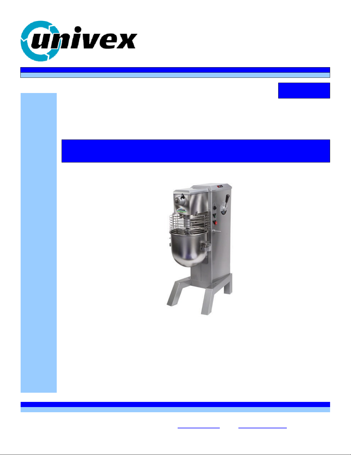
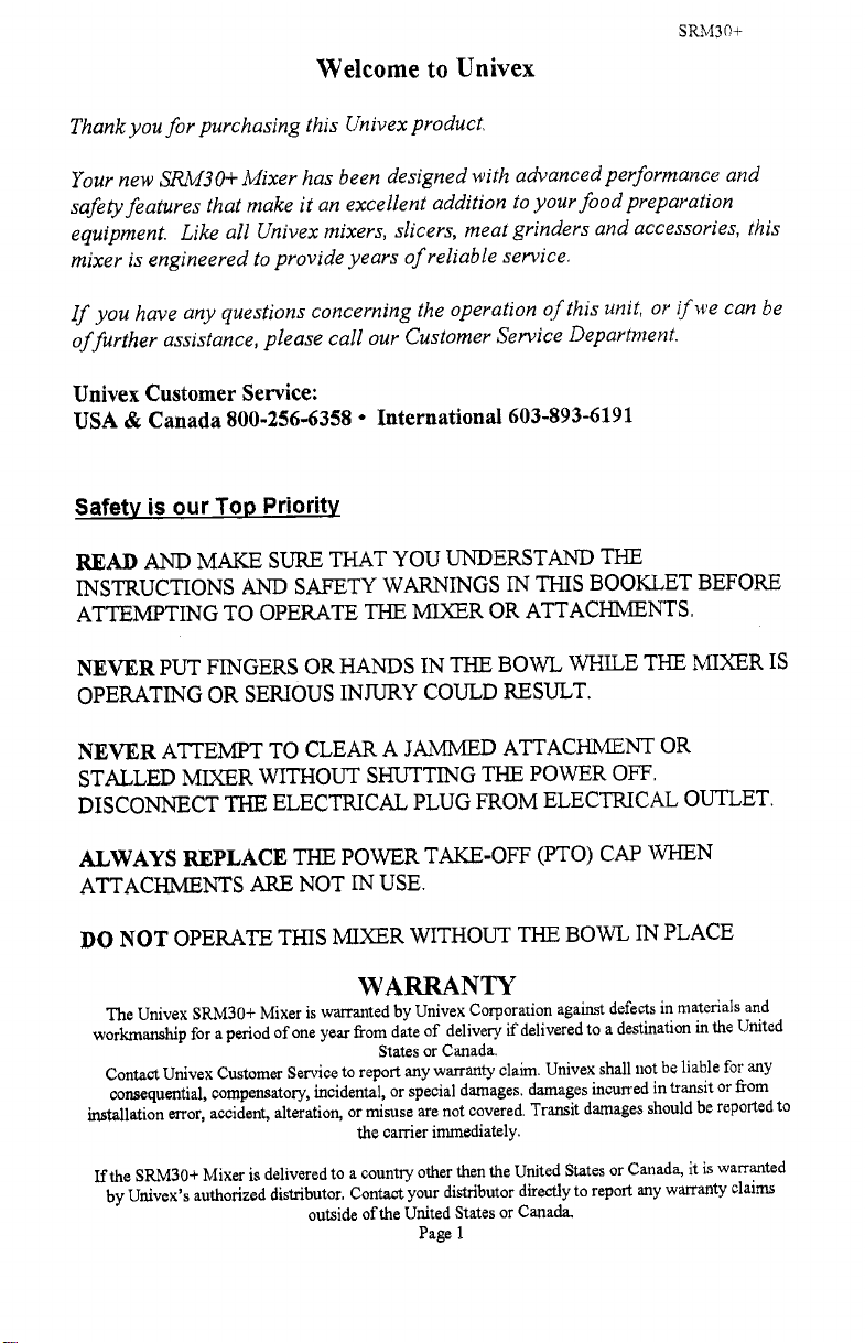
Swing Ring Series
SSwwiinngg RRiinngg SSeerriieess
SRM3O+ PLANETARY MIXER
R
SSR
Persons under the age of 18 are not permitted to operate or have
Persons under the age of 18 are not permitted to operate or have
accessibility to operate this equipment per U.S. Dept. of Labor Employment
accessibility to operate this equipment per U.S. Dept. of Labor Employment
M3300++ PPLL
M
Maintenance & Parts Manual
Maintenance & Parts Manual
Standards Administration Fact Sheet No. ESA91-3.
Standards Administration Fact Sheet No. ESA91-3.
A
NEETT
A
N
A
A
RYY
R
MIIXXEE
M
R
R
UNIVEX CORPORATION - 3 Old Rockingham Road - Salem, NH 03079-2140 - Tel (800) 258-6358 - Fax (800) 356-5614
UNIVEX CORPORATION - 3 Old Rockingham Road - Salem, NH 03079-2140 – Tel (800) 258-6358 – Fax (800) 356-5614
Int'l Tel 603-893-6191 - Int'l Fax 603-893-1249 - Website www.univexcorp.com - E-mail Univex@univexcorp.com
ED5 SRM3O+/0304
ED5 SRM30+/0304 Printed in USA
PDF compression, OCR, web optimization using a watermarked evaluation copy of CVISION PDFCompressor
Int’l Tel 603-893-6191 – Int’l Fax 603-893-1249 – Website www.univexcorp.com - E-mail Univex@univexcorp.com
Printed in USA
SRM3Q+
Welcome to Univex
Thank you for purchasing this Univex product.
Your new SRIvI3O+ Mixer has been designed with advanced performance and
safely features that make it an excellent addition to your food preparation
equipment. Like all Univex mixers, slicers, meat grinders and accessories, this
mixer is engineered to provide years of reliable service
If you have any questions concerning the operation qf this unit, or if we can be
offurther assistance, please call our Customer Service Department.
Univex Customer Service:
USA & Canada 800-256-6358
Safety ¡s our Tqp Priority
READ AND MAKE SURE THAT YOU UNDERSTAND THE
INSTRUCTIONS AND SAFETY WARNINGS IN THIS BOOKLET BEFORE
ATTEMPTING TO OPERATE THE MIXER OR ATTACHMENTS.
International 603-893-6191
NEVER PUT FINGERS OR HANDS IN THE BOWL WHILE THE
MIXER IS
OPERATING OR SERIOUS INJURY COULD RESULT.
NEVER ATTEMPT TO CLEAR A JAMMED ATTACHMENT OR
STALLED MIXER WITHOUT SHUTTING THE POWER OFF.
DISCONNECT THE ELECTRICAL PLUG FROM ELECTRICAL OUTLET.
ALWAYS REPLACE THE POWER TAKE-OFF (PTO) CAP WHEN
ATTACHMENTS ARE NOT IN USE.
DO NOT OPERATE THIS MIXER WITHOUT THE BOWL
WARRANTY
The Univex SRM3O+ Mixer is warranted by Univex Corporation against defects
workmanship for a period of one year from date of delivery if delivered to a destination
States or Canada.
Contact Univex Customer Service to report any warranty claim. Univex shall not
consequential, compensatory, incidental, or special damages. damages incurred in transit or
installation error, accident, alteration, or misuse are not covered. Transit damages
the carrier immediately.
If the SR.M30+ Mixer is delivered to a country other then the United States or
by Univex's authorized distributor. Contact your distributor directly to report any
outside of the United States or Canada.
Page 1
PDF compression, OCR, web optimization using a watermarked evaluation copy of CVISION PDFCompressor
IN PLACE
in materials and
in the United
be liable for any
from
should be reported to
Canada, it is warranted
warranty claims

SRM3O-
TABLE OF CONTENTS
DESCRIPTION PAGE
WARRANTY
TABLE OF CONTENTS, LIST OF ILLUSTRATIONS
CHOOSING THE RIGHT LOCATION FOR YOUR NEW MIXER
USER-FRIENDLY SWING RING'TM SAFETY GUARD
OPERATING THE SRM3O+ MIXER
USING THE POWER TAKE-OFF (PTO)
TABLE OF MIXING CAPACITIES & RECOMMENDED AGITATOR
BATTERS, AGITATORS, BOWLS, & ACCESSORIES
CLEANING YOUR MIXER
OPERATOR'S PREVENTIVE MAINTENANCE
TROUBLE SHOOTING GUIDE
REMOVAL OF TOP COVER
MECHANICS MAINTENANCE
REPAIR INSTRUCTIONS
REPLACEMENT PARTS, LISTS
WIRING DIAGRAMS
LIST OF ILLUSTRATIONS
ILLUSTRATION
FIGURE 1
FIGURE 2
FIGURE 3
FIGURE 4
FIGURE
FIGURE 6
FIGURE 7
FIGURE 8
FIGURE 9
FIGURE 10
FIGURE 11
FIGURE 12
OVERALL VIEW OF MIXER
LUBRICATION INSTRUCTIONS
TRANSMISSION
BEATER HEAD ASSEMBLY
5
POWER TAKE OFF ASSEMBLY
INPUT ASSEMBLY
VERTICAL SHAFT ASSEMBLY
BOWL LIFT ASSEMBLY
BOWL SUPPORT ASSEMBLY
SPEED CONTROL ASSEMBLY
VARI-SPEED AND DRIVE SYSTEM
HOUSING ASSEMBLY
FIGURE 13A WIRING DIAGRAM 115/208-240 V, 60HZ, 1PH,
220-240V, 50HZ, 1PH, 100V, 50/60HZ, 1PH
FIGURE 13B WIRING DIAGRAM 380-400 V, 50HZ, 3PH, 460V, 60HZ, 3PH
FIGURE 13C WIRING DIAGRAM 208-240 V, 60HZ, 3PH,
220-240 V, 50HZ, 3PH
I
2
3
3 & 4
4 - 6
6
7
8
10
lo
li & 12
13
13 & 14
15 - 19
20 - 31
32 -34
PAGE
9
14
20
21
22
23
24
25
26
27
28 - 29
30 - 31
32
33
34
Page 2
PDF compression, OCR, web optimization using a watermarked evaluation copy of CVISION PDFCompressor
CHOOSING THE RIGHT LOCATION FOR YOUR NEW MIXER.
When selecting the best location for the mixer, it is helpful to consider the following:
Where is the best location for the operator, both for saving steps and easy
viewing?
Is this a good location for product flow as in:
Easy to get ingredients to the mixer?
Destination of the mix after mixing?
Is there existing electrical service at this location?
Does this location provide easy access for cleaning and service?
Check to be sure that your mixer with attachments does not extend out
into heavy traffic areas,
If stands and/or portable equipment are used along side of your mixer,
can they be moved easily to and from your mixer?
The chrome cap plugs included in your manual package are supplied to
cap shipping bolt holes (Fig. 1 [16]) in mixer base if base is not anchored.
If unit is not provided with a plug, then the unit is to befitted with a primary disconnect
device that has a contact separation of at least 3mm in all poles.
SRM3O+
IMPORTANT ELECTRICAL SERVICE INFORMATION
Electrical wiring instructions are found in the wiring diagram (Figures 13A thru 13C). Before making
electrical connections, CHECK the specifications on the nameplate to make sure that they agree with
those on your electric service.
USER-FRIENDLY SWING RING'TM SAFETY GUARD
Your SRM3O+ Mixer features a newly updated, 2-part safety guard. The Swing Ringan Safety Guard
ring is easily be removed and installed, as well as dishwasher safe. It conveniently swings out of the way
without having to be remove to place or sample ingredients in the bowl. Only one side of the guard
needs to be open when adding ingredients. You'll fmd this two-piece design is easy to handle and fits
conveniently in your sink or dishwasher. lt also provides a clear view of the product throughout the
mixing cycle.
This mixer wifi not operate unless the Swing Ringan Safety Guard is properly engaged.
Metal tabs at the rear of the guard activate twin switches that enable the mixer to run only when the
guard is securely closed. These switches protect against accidental operation of the mixer when the
safety guard is open or removed from the mixer. The mixer will automatically stop if the guard is open.
Additional switches in the bowl slide mechanism automatically stop the mixer if the bowl is lowered
from the "up" (mixing) position.
To Install the Swing Ringan Safety Guard, insert the pointed end of the rod at the rear of the guard into
the lower mounting bracket on the mixer housing. Then insert the top end of the rod into the upper
bracket by aligning the groove in the rod with the slot in the bracket. Press the rod in and allow itto drop
Page 3
PDF compression, OCR, web optimization using a watermarked evaluation copy of CVISION PDFCompressor
SRM30-
down into position. Repeat this for each of the two sections of the guard. Swing the two halves of the
guard forward. When the guard is properly closed, the switches are now activated and the mixer can be
operated.
To remove the guard, simply reverse the installation procedure. Grip the two halves of the guard and
pull it open. Use an upward motion to release each half of the guard from the bracket on the machine
body.
To open the guard for access to the bowl, first turn the mixer off by pushing the red stop button
(Fig.i El 3]). Pull open the two halves of the guard and swing one or both outward. It is not necessary to
remove them, Close the guard to resume mixing operations.
OPERATING THE SRM3O+ MIXER
Your Univex Mixer is designed to meet the cook's and Baker's demand for an efficient, dependable
appliance. It should give unfailing performance over a period of years when operated and maintained
according to the instructions contained herein.
The mixer drives various agitator attachments through a beater head shaft to beat, mix, or whip liquid,
viscous, or dry ingredients. The shaft is driven by a study motor whose power is transmitted by a rugged,
cogged belt and a Continuously Variable Transmission (CVT) through a gear train and a planetary gear
set, The speed of the beater shaft can be varied from approximately 80 to 370 revolution per minute
(rpm). (See page 8 for part numbers of various agitators, attachments and accessories.)
The SRM30+ Mixer is equipped with a power take-off (PTO) that operates other attachments such as
slicers, graters and grinders. The PTO speed can be varied from 65 to 300 rpm Be sure to read and
follow any safety instructions provided by the manufacturers of attachjnent.s that you operate on
the PTO. The PTO hub should be covered with the PTO cap provided with your mixer when in use.
Warnlng---Never put hands, spoons, utensils or other objects into the bowl while the mixer Is
operating!
Note: Noise emissions are below 70db (A).
Securing the Bowl & Installing the Mixer Agitator.
Place the bowl on the bowl support (Fig. 1 [17]). The pin at the rear of the bowl must align with the
corresponding slot on the bowl support. Align the holes in the bowl mounting brackets over the pins on
the bowl support and lower the bowl into position. Secure the bowl by turning the bowl clamps (Fig. 1
[181).
With the bowl in the "down" position, install the desired agitator by sliding it upward onto the beater
shaft (Fig. 1 [1]). Rotate the agitator counter-clockwise until it is engaged.
Safety Note Serious injury may result if the bowl is not fully secured to the bowl support using the
bowl support pins and firmly closing the clamps.
With the bowl secured, add ingredients. Liquids should be added first. The bowl is now ready to be
raised to the "up" (mixing) position by turning the bowl lift handle (Fig. l[14]) clockwise.
When using the wire whip agitator, raise the bowl to the "up" position first and then add ingredients to
avoid wire whip damage.
Secure and close the Swing Ring" Safety Guard before proceeding.
Page 4
PDF compression, OCR, web optimization using a watermarked evaluation copy of CVISION PDFCompressor

SRM30+
Using the Bowl Lift
The mixer will not operate unless the bowl is in the "up "position. Raise the bowl by turning the bowl
lilt handle (Fig. 1 [14]) clockwise. To lower the bowl, turn the handle counter-clockwise. it is
to lower the bowl to change the agitator. This also makes the bowl accessible for filling
necessary
Setting the Timer - Start/Stop Controls
This mixer will not operate unless the timer has been set to a specified number of minutes or set in the
"HOLD" position. To start the mixer, first turn the timer dial (Fig. 1 [8])to the desired mixing time.
Then push the start button (Fig. 1 [12]). The mixer will automatically stop when the tinier reaches "0".
To stop mixing before the timer reaches "0", push the red stop button (Fig. 1 [13]).
The timer may be set for up to 15 minutes of mixing, or maybe set to the "HOLD" position for
continuous operation. When setting a time of less then 5 minutes, turn the dial beyond 5 minutes and
then return it to the desired time.
Safety Note The mixer will start only when the Swing RingTMSa.fety Guard is engaged and the bowl is
in the raised position. Do not operate the mixer without the bowl in place.
Manual Stop Button
For safety and operational ease, this mixer is equipped with a stop button (Fig.l [13]) that has an
oversized, red mushroom-style cap.
Safety Note Although the motor shuts off instantly when the Swing RingTM Safety Guard is opened, or
the bowl is lowered, or the stop button is pushed, the agitator may not come to complete rest for several
revolutions. Do not put hands or utensils into bowl or near the beater shaft until it is stopped.
Both the start button and stop button are momentary contact type. They provide low voltage protection
and prevent accidental start-up in the event of power interruption.
Vail-Speed Control
A major advantage of Univex mixers is their Continuously Variable Transmission (CVT). Unlike other
mixers, CVT lets you change speed while the mixer is running. Change speed by moving the speed
control lever (Fig. 1 [9]) to the desired level. The speed indicator (Fig. 1 [10]) shows four speeds.
-
Numerous intermediate speeds give the Cook or Backer tremendous flexibility.
Use speed i (slow) for heavy mixtures like pizza, bread or roll dough. Speed I should also be used with
the Meat and Food Chopper attachment. For most mixing tasks, start on speed i and progress to higher
speeds as needed. Use high speeds for wipping cream, beating eggs, and thin batter. To avoid damaging
your mixer, follow the speed, volume limits and attachments recommendations shown in the
Table of Mixing Capacities on page 7.
If you notice any slippage during mixing, the mixer may be overloaded. Reduce the load, or reduce
speed until mixing action is smooth. Refer to the Trouble- Shooting Guide on page 11 & 12.
if the mixer jams and the motor stalls, immediately press the stop button. Take necessary steps to reduce
the load. Never put hands in the bowl to clear a jam.
Note Always return to speed i before shutting off the mixer. Do not move the speed control lever
when the mixer is not running, because this will cause belt to become loose and the mixer will not
operate properly.
Page 5
PDF compression, OCR, web optimization using a watermarked evaluation copy of CVISION PDFCompressor
SRM3O±
1f the mixer has been shut off by the timer, or stop button in speed 2, 3 or 4, follow these steps to
avoid belt slippage or Jerky start: Empty the bowl. Set the timer to 'HOLD". Press the start button.
As the mixer begins to operate, move the speed control lever back to speed 1. Press the stop button.
Retum to "0". Your mixer is now ready for it's next task.
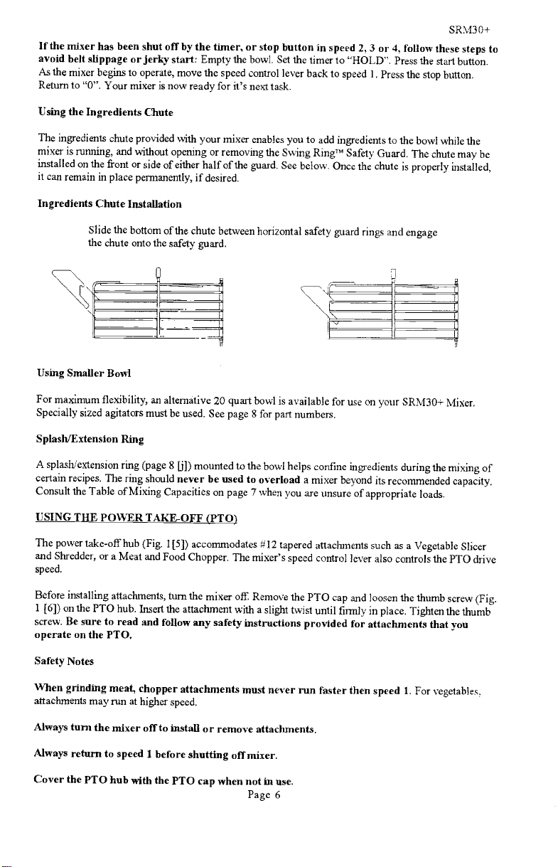
Using the Ingredients Chute
The ingredients chute provided with your mixer enables you to add ingredients to the bowl while the
mixer is running, and without opening or removing the Swing RingTM Safety Guard. The chute
installed on the front or side of either half of the guard. See below. Once the chute is properly installed,
it can remain in place permanently, if desired.
may be
Ingredients Chute Installation
Slide the bottom of the chute between horizontal safety guard rings and engage
the chute onto the safety guard.
Using Smaller Bowl
For maximum flexibility, an alternative 20 quart bowl is available for use on
Specially sized agitators must be used. See page 8 for part numbers.
your SRM3O+ Mixer.
Splash/Extension Ring
A splash/extension ring (page 8 [j]) mounted to the bowl helps confine ingredients during the mixing of
certain recipes. The ring should never be used to overload a mixer beyond its recommended capacity.
Consult the Table of Mixing Capacities on page 7 when you are unsure of appropriate loads.
USING THE POWER TAKE-OFF (PTO)
The power takeoff hub (Fig. 1 [5]) accommodates
and Shredder, or a Meat and Food Chopper. The mixer's speed control lever also controls the PTO drive
speed.
Before installing attachments, turn the mixer off. Remove the PTO cap and loosen the thumb
1 [6]) on the PTO hub. Insert the attachment with a slight twist until firmly in place. Tighten the thumb
12 tapered attachments such as a Vegetable Slicer
screw (Fig.
screw. Be sure to read and follow any safety instructions provided for attachments that you
operate on the PTO.
Safety Notes
When grinding meat, chopper attaclunents must never run faster then speed 1. For vegetables.
attachments may run at higher speed.
Always turn the mixer off to install or remove attachments.
Always return to speed 1 before shutting off mixer.
Cover the PTO hub with the PTO cap when not in use.
Page 6
PDF compression, OCR, web optimization using a watermarked evaluation copy of CVISION PDFCompressor

Table of Mixing Capacities & Recoimnended Agitators
SRM3O+
MODEL
Bowl Capacity
Attachment Hub Size
Motor
Kitchen Capacities (single
batches)
Mashed potatoes
Whipping cream
Mayonnaise
Egg whites
Meringue
Waffle or pancake batter
Bakery Capacities (single
batches)
Pie dough
Cake
Sponge cake batter
Angle food batter (8-10 oz
cake)
Marshmallow icing
Fondant icing
Shortening & sugar creamed
Egg & sugar for sponge cake
Use only speed 1 for:
Pizza dough
thin, 40% AR
medium, 50% AR
thick,60%AR
Agitator(s)
Batter beater, 4-wing beater
Wire whip, 4-wing beater
Batter beater, wire whip,
4-wing beater
Wire whip
Wire whip
Batter beater
Agitator(s)
Pastryknife
Batter beater, 4-wing beater
Wire whip, 4-wing beater
Wire whip, 4-wing beater
4-wing beater
Batter beater
Batter beater
Batter beater, 4-wing beater
Dough hook
Dough hook
Doughhook
SRM3O+
36 qt
#12
lhp
23 lb
6 qt
12 ql (oil)
I 1\2 ql
1 qt (water)
12 qt
271b
30 lb
18 lb
22 cakes
3 Ib
18 Ib
24 lb
12 Ib
14 Ib
20 Ib
401b
34 L
10.5 kg
5.7 L
11.4 L (oil)
1.4 L
0.9 L (water)
11 .4L
12.3 kg
13.7 kg
8.2 kg
22 cakes
1.4 kg
8.2 kg
10.9 kg
5.5 kg
6.4 kg
9.1 kg
18.2kg
Use speed 1 or 2 for:
Raised doughnut dough
65%AR
Bread/roll dough
heavy, 55%AR
light to med., 60% AR
Doughhook
Doughhook
Dough hook
l5Ib
301b
45 lb
ÑOTES: Recommended speeds are for the capacities listed. For larger capacities, reuuc
speed. Dough capacity, whether for bread, rolls, pizza, bagels or
based on 12% flour moisture and 70°F (2 1°C) water temperature
capacity if cold water is used. If higher gluten flour is used, reduce
capacity by 10%.
AR% (Absorption Ratio) = the weight of the water divided by
weight of the flour.
The lower the AR% the stiffer and more difficult the dough is to
6.8kg
13.7kg
20.5 kg
doughnuts, is
Reduce
total
the
mix.
A.R% below 40% will reduce total capacity.
1 gallon of water = 8.3 Ib. (1 liter of water = 2.2lb)
Page 7
PDF compression, OCR, web optimization using a watermarked evaluation copy of CVISION PDFCompressor
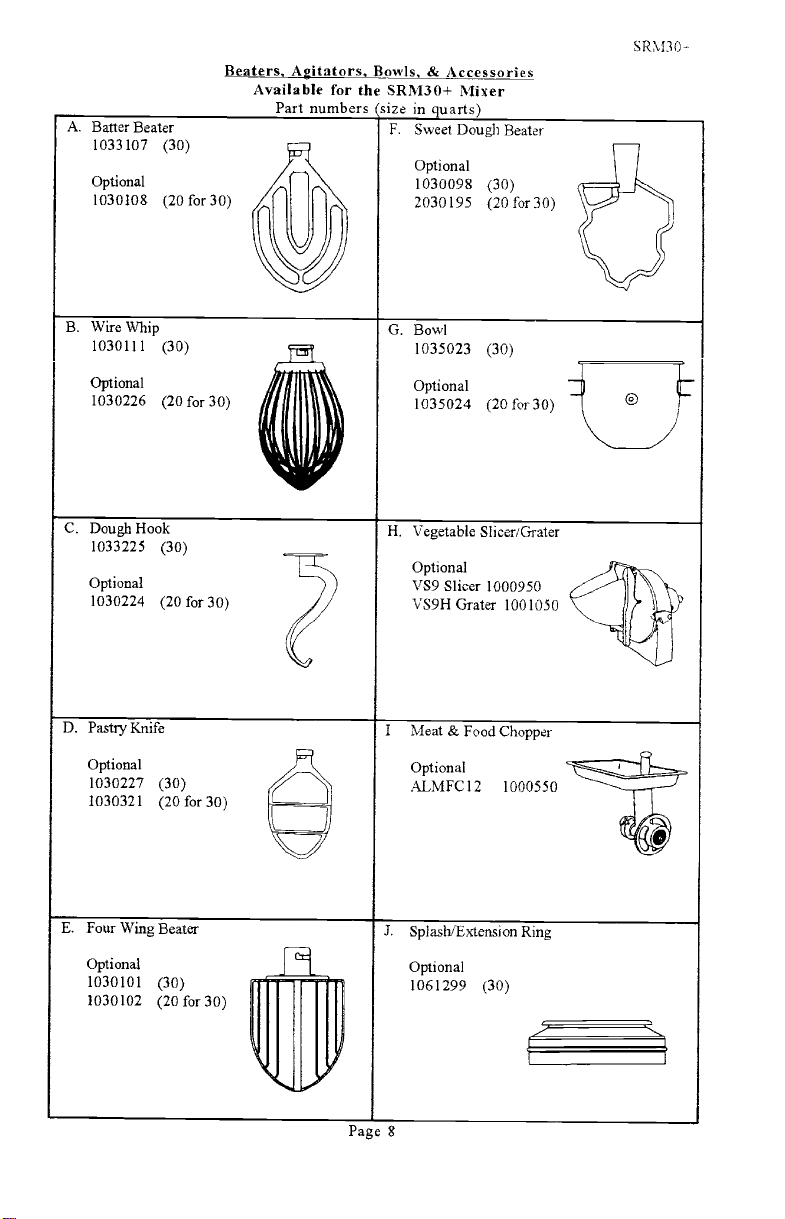
A. Batter Beater
1033107
Optional
1030108
(30)
(20for30)
Beaters. Agitators, Bowls, & Accessories
Available for the SRM3O+ Mixer
Part numbers (size in auarts
F.
Sweet Dough Beater
Optional
1030098
2030195
(30)
(20 for 30)
SRM3O
*
B. Wire Whip
1030111
Optional
1030226
C. Dough Hook
1033225
Optional
1030224
D. Pastry Knife
Optional
1030227
1030321
(30)
(2Ofor3O)
(30)
(2Ofor3O)
(30)
(2Ofor3O)
r:î
1,f'
G, Bowl
1035023
Optional
1035024
H. Vegetable Slicer/Grater
Optional
VS9 Slicer 1000950
VS9H Grater 1001050
I
Meat & Food Chopper
Optional
MFC12
(30)
(2Ofor3O)
1000550
E. Four Wing Beater
Optional
1030101
1030102
PDF compression, OCR, web optimization using a watermarked evaluation copy of CVISION PDFCompressor
(30)
(2Ofor3O)
J.
Splash/Extension Ring
Optional
1061299
Page 8
(30)
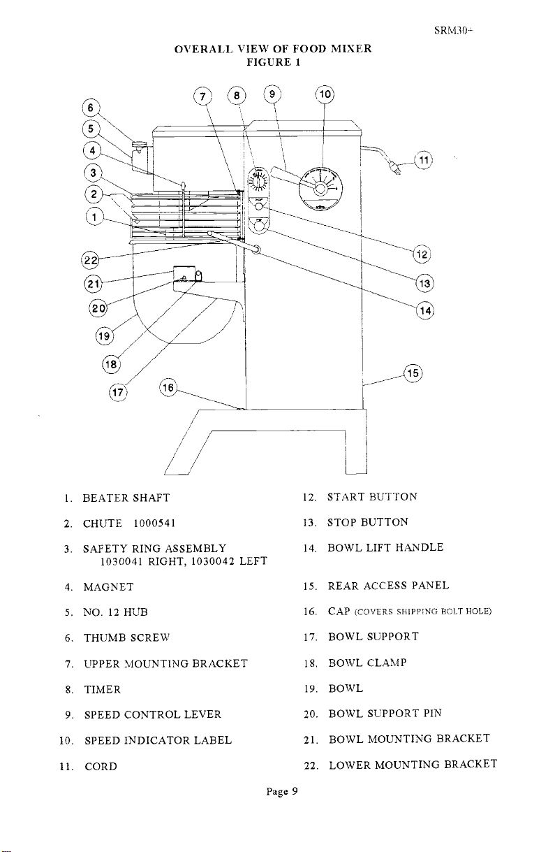
OVERALL VIEW OF FOOD MIXER
FIGURE 1
SRM3O--
START BUTTON
BEATER SHAFT
1.
CHUTE 1000541
2.
SAFETY RING ASSEMBLY
3.
12.
STOP BUTTON
13.
14. BOWL LIFT HANDLE
1030041 RIGHT, 1030042 LEFT
4. MAGNET
5. NO. 12 HUB
6. THUMB SCREW
7. UPPER MOUNTING BRACKET
8. TIMER
SPEED CONTROL LEVER
9.
SPEED INDICATOR LABEL
10.
11. CORD
15. REAR ACCESS PANEL
16. CAP (COVERS SHIPPING BOLT HOLE)
17. BOWL SUPPORT
18. BOWL CLAMP
19. BOWL
20. BOWL SUPPORT PIN
21. BOWL MOUNTING BRACKET
22. LOWER MOUNTING BRACKET
Page 9
PDF compression, OCR, web optimization using a watermarked evaluation copy of CVISION PDFCompressor

SRM3ft-
CLEANING YOUR MIXER
Consistent use of the following procedures will ensure that your mixer is in optimum
conditi on.
u
Warning -
Disconnect electric power supply before cleaning.
Wash the body of the mixer, the bowl support. and beater shaft with warm water and
mild soap,
Avoid excess water in the area of the safety switch that protrude from the housing
where the Swing RingTM Safety Guard is mounted.
Do not rinse with a hose.
Do not use abrasive pads.
Dry the mixer thoroughly using a soft cloth.
Wash the bowl and beater immediately after use. If egg mixtures or flour hatter have
been used, rinse the bowl and batter with cold water before washing with hot water.
Wash the Swing
RingTM
Safety Guard in the same manner, or in your dishwasher.
Dry bowls, agitators and safety guard thoroughly.
OPERATOR'S PREVENTIVE MAINTENANCE
For best long-term performance, operators should follow these simple practices.
Lightly lubricate the beater shaft (Fig.
1 [l}) after washing. Petro-Gel or equivalent
food grade lubricant should be used.
u
Do not cover the unit with a plastic bag, as this traps humidity in
If the electrical supply cord is damaged, it must be replaced by
assembly
your mixer.
a special cord or
available from Univex directly or from a Univex service agent.
Do not overload the mixer. Overloading is the #1 cause of mixer failure, Follow
the Table of Mixing Capacities on page 7. It may be helpful to post
table adjacent to the mixer.
a copy of this
Keep the mixer properly lubricated. Lack of lubrication is 2 cause of mixer
failure. Key mixer components require lubrication after each 500 hours of operation.
(Instructions on frequency and method of lubricating are on page 14).
Only change speed with the mixer running. Changing speed with mixer off will
loosen, and the mixer will not turn (see Trouble-Shooting Guide on
speed 1 before shutting the mixer off. Use the procedure described
speed i if mixer is shut off in a higher speed.
page 11 & 12). Return to
on page 6 to return the mixer to
cause belts to
Page lO
PDF compression, OCR, web optimization using a watermarked evaluation copy of CVISION PDFCompressor

TROUBLE
Mixer will not
operate.
SRM3O+ TROUBLESHOOTING GUIDE
POSSIBLE CAUSE
1. 1 Timer not turned on.
1.2 Burned switch contacts
i
i Turn timer on.
1.2 Replace. *
SRM3O±
REMEDY
2. Mixer runs but
agitator will not
turn,
3. Agitator stalls
during mixing
1.3 Electrical service down.
1.4 Motor capacitor defective.
(1 HP Only)
1.5 Burned out motor.
1.6 Magnetic starter tripped
due to overload
1.7 SAFETY RING not
mounted and closed.
1.8 Bowl not raised,
2,1 Drive belt off pulley
2.2 Key or Pin sheared on input
shaft, input gear, bevel
pinion, bevel gear, vertical
shaft or beater shaft.
2.3 Shifting speed with mixer
not running.
3.1 Mixer bowl is overloaded
1.3 Check electrical service.
Replace fuse or reset
circuit breaker if necessary.
1.4 Replace. *
1.5 Remove, test, repair or
replace. *
1.6 Wait several minutes and
push start button
1.7 Install SAFETY RING.
1.8 Raise bowl conwletelv
2.1 Reinstall drive belt on
motor pulley and adjust
mount center distance. *
2.2 Locate by step inspection
and replace defective part.*
2.3 With mixer running, slowly
move speed control lever
slowly fully forward then
backward to re-engage belt
3. 1 Adjust contents of bowl per
Mixing Capacities Table
4. Speeds do not
3.2 Speed is set too high for the mix
3.3 Loose belt
3.4 Contamination of belt with
grease
4.1 Loose belts.
3.2 Shift speed lower till action
rotates smoothly
3.3 Readjust pulley center distance
to tighten belt. *
3.4 Clean pulleys and replace belt *
4.1 Tighten or replace belts. *
change properly
4.2 Van-Speed pulley
inoperative
Page 11
PDF compression, OCR, web optimization using a watermarked evaluation copy of CVISION PDFCompressor
4.2 Remove, clean & lubricate,
or replace. *

SRM3O+ TROUBLESHOOTING GUIDE
SRM3O
(CONT'D).
Mixer runs, but
repeatedly cuts
out and stops
Attachments
contact bottom
of bowl.
Attachments
contact side of
bowl
Excessive
noise.
5.1 Bowl overloaded
5.2
Speed is set too high for
the mix
5.3
Service voltage too low or
fluctuating
5.4
Starter improperly set
6.1 Dented bowl.
6.2 Bowl height is set too high
7.1 Dented bowl
7.2 Insufficient clearance
between bottom of howl and
beater.
8.1 Gears need to he repacked
with grease.
8.2 Badly worn or frayed drive
belts.
8.3 Attachments hitting bowl
8.4 Overloaded mixing bowl
5.1 Adjust contents of bowl
per Mixing Capacities
Table
5.2 Reduce speed
5.3
Check electrical voltage.
5.4 Adjust amp setting on
starter.
*
6.1 Remove dent or replace
howl.
6.2 Reset bowl height.
7.1 Remove dents or replace bowl
7.2 Adjust bowl height.
*
*
8.1 Locate source by
inspection and repack
with grease.
8.2 Replace belts.
*
*
8.3 Inspect for cause in items
6 and 7 above.
8.4 Adjust contents of bowl
per Mixing Capacities
Table
*
*
Remedies designated with a
*
require the services of an authorized service agent.
Page 12
PDF compression, OCR, web optimization using a watermarked evaluation copy of CVISION PDFCompressor

SRM3O+
REMOVAL OF TOP COVER
The top cover (Fig. 12 [17]) must be removed in order to perform the maintenance
operations.
rearward end.
SAFETY. Then, remove the screw in the rear (Fig. 12 [21]), lift
push forward about 3 inches and lift cover off.
It is secured by a spring clip at its front end and a screw at its
First, DISCONNECT THE ELECTRICAL POWER FOR
rear of cover,
Reinstall in reverse procedure using care to insure that the cover sits squarely
uniformly on the mìxer housing.
MECHANICS MAINTENANCE
Every six months a mechanic should perform the following inspection and maìntenance
required:
i. BELTS
WARNING: Start mixer and adjust speed control (Fig. I [9]) to speed 4. Stop
mixer. FOR SAFETY, DISCONNECT POWER.
Remove top cover (Fig. 12 [17]) and rear access panel (Fig. 12 [24]).
Check belts (Fig. 11 [11 & 22]). If broken, glazed or worn, replace.
Check belt (Fig. 11 [11]) for proper tension. The outer edge of the belt should be
flush with the outer diameter of the variable speed pulley (Fig. il [10]).
If not,
adjust by loosening the Jam Nut (Fig. 10 [15]) and turning the connecting rod
(Fig. 10 [14]) until the outer edge of belt is flush with the outer diameter of the
pulley. Retighten Jam Nut.
WARNING: Plug machine in. start mixer, and adjust speed control to speed 1.
Stop mixer. FOR SAFETY, DISCONNECT POWER.
Check belt (Fig. 11 [22]) for proper tension. The outer edge of the belt should be
flush with the outer diameter of the variable speed pulley (Fig. li [10]). If not,
adjust by loosening nuts (Fig. Il [14]), holding motor (Fig. 11 [29]), raise
lower the motor until the outer edge of belt is flush with the outer diameter of
pulley. Retighten Nuts.
and
as
or
MOTOR
Check motor (Fig. Il [29]) for overheating, noise and excessive end play. Replace
if defective.
BOWL LIFT ADJUSTMENT (Fig. 8 and 9)
Place 30 qt. mixing bowl on bowl support (Fig. 1 [17]) and 30 qt. batter beater
beater shaft (Fig. 1 [1]).
on
Raise bowl support to the high position.
Check clearance between bottom of bowl and lowest point of batter beater.
Clearance should be 3/16 inch. plus or minus 1/16 inch.
If adjustment is required, disconnect power, loosen lock nut (Fig. 8 [10]) and turn
linkage rod (Fig. 8 [9]) until desired clearance is obtained. Retighten lock nut.
Page 13
PDF compression, OCR, web optimization using a watermarked evaluation copy of CVISION PDFCompressor

SRM3O+
4. LUBRICATION
The lubrication instructions are in Fig. 2. Motors have pre-lubricated bearings with a
service interval often years. The transmission and beater head gearing are packed with
Nevastane 5p7 grease. They must be repacked every 500 hours of mixing time.
WARNING: NEVER WORK ON THE TRANSMISSION WITH THE MIXER
RUNNING. IT IS RECOMMENDED THAT THE ELECTRICAL SERVICE
BE DISCONNECTED TO PREVENT ACCIDENTAL START UP.
LUBRICATION INSTRUCTIONS
FIGURE 2
OIL YEARLY.
MEDIUM (NO. 30)
MACHINE OIL.
Bowl Lift
Slide
GREASE EVERY 500
HOURS OF MIXING TIME
KEYSTONE
NEVASTANE SF7
GREASE YEARLY
MOLYKOTE BR2 PLUS.
Page 14
PDF compression, OCR, web optimization using a watermarked evaluation copy of CVISION PDFCompressor

(including disassembly, replacement and reassembly)
REPAIR INSTRUCTIONS
TRANSMISSION (Fig. 3)
Removal
WARNING: DISCONNECT POWER FOR SAFETY.
Remove housing top cover (Fig. 12 [17]).
3, Adjust speed control to low speed, then back to high speed, remove upper
retainer bracket (Fig. 11 [16]), and upper V-belt (Fig. 11 [11]) from
transmission drive pulley (Fig. 11 [12]). Remove drive pulley.
Caution: Transmission assembly is heavy and must be supported prior to
removing. Remove four cap screws (Fig. 3 [10]) securing transmission housing
to mixer housing. Remove transmission assembly and place on work bench.
Remove transmission cover (Fig. 3 [2]) by removing four screws (Fig. 3 [3])
and sliding towards the rear and lifting up.
Rotate gear train by hand and inspect for worn or chipped gears, bent shafts,
worn bearings and excessive back lash; removal of grease may be necessary.
Back lash measured at gear teeth exceeding 1/32" is considered excessive.
After trouble has been isolated, proceed to disassemble.
Disassembly
1. Beater Head Assembly (Fig. 4)
SRM3O+
NOTE: If a gear requires replacement. always replace it's mating gear.
Remove cap screw, left hand thread, (Fig. 4 [12]) and remove beater head
assembly using jacking screws (Fig. 4 [9]) if necessary.
Remove drive pin (Fig. 4 [1]), retaining rings (5), gear (6), key (3),
retaining ring (7), and press shaft (2) and bearings (4) from housing (10).
e.
Press bearings (4) along with spacer (8) from shaft (2)
2. Power-Take-Off Assembly (Fig.
Remove three cap screws (Fig.
5)
5 [8 & 21]),
washer (6 & 7), deflector (5)
retaining ring (3), at gear (12) end of shaft. Withdraw the PTO assembly
from the transmission housing.
NOTE: Gear (12) must be removed during withdrawal of PTO assembly.
Slide retaining ring (3) and bevel gear (li) away from PTO housing (4).
Remove retaining ring (10) and adapter (2). Press shaft assembly from
housing (4).
Remove retaining rings (3), key (14 & 17). Press bearings (9) and gear (11)
from shaft (13).
Page 15
PDF compression, OCR, web optimization using a watermarked evaluation copy of CVISION PDFCompressor

3. Input Assembly (Fig. 6)
Remove screw (Fig 6 [11]) and washers (12 &13) to detach grease retainer
(14) from housing (S)
Remove two cap screws (Fig. 6 [10]) and remove input assembly from
transmission.
Remove retaining rings (1). gear (2), woodruff key (5). Press shaft (6) at
gear end with bearing (4) from housing (8).
Remove retaining rings (3) and press bearing (4) from housing (8).
Remove retaining ring (1) and press shaft (6) from bearing (4).
Note: Grease retainer can only be removed from gear box once the PTO
gear (Fig. 5 [12]) has been removed.
4. Vertical Shaft Assembly (Fig. 7)
Remove retaining ring (1) from shaft (5).
SRM3O+
Drive shaft
housing. A brass drift will be necessary to drive shaft
(5)
and lower bearing (3) downward out of transmission
(5)
completely free
from transmission housing.
Lift bevel gear (2) and key (6) from transmission housing.
Remove retaining ring (4) and drive upper hearing (3) from transmission
housing.
Remove key (7) and press lower bearing (3) off shaft (5).
Reassembly
Clean all components, except bearings with safety approved cleaning
solvent. Inspect components for defects and replace those found to be
defective.
NOTE: All gears should be replaced as sets.
If shafts have become slightly scored during the disassembly process, polish
the shafts with fine machinists crocus cloth. Use care to avoid excessive
removal of shaft surface or proper fit of components will be lost.
e.
Reassembly should be carried out in the reverse of the disassembly
procedure as follows.
Vertical shaft assembly.
PTO assembly except spur gear (Fig 5 [12]).
Place grease retainer (Fig 6 [14]) in place in transmission housing (Fig 3
[1]), then assemble gear (Fig 5 [12]) associated with PTO assembly, then
slide input housing assembly in place and finally attaching grease
retainer (Fig 6 [14]) back onto input housing (Fig 6 [8]) with screw (Fig
6 [11]). Attach input housing to transmission housing with screws (Fig 6
[10]).
PDF compression, OCR, web optimization using a watermarked evaluation copy of CVISION PDFCompressor
Page 16

Transmission should be progressively checked for smooth operation while on
the workbench by hand turning each assembly as it ìs installed.
Lubrication of the transmission should be done following its installation on
the mixer. Apply Keystone Nevastane 5p7 grease to the spur gear and bevel
gear meshes. This may be simplified by feeding the grease into the rotating
gear meshes. Caution should be exercised to avoid entrapment of the
application implement in the gear teeth.
positioned to dynamically guide the lubrication into the bevel gear mesh.
BOWL SUPPORT ASSEMBLY: (Fig. 9)
WARNING: Disconnect electrical power for safety.
Remove housing top cover (Fig. 12 [17]) and rear access panel Fig. 12 [24)).
Remove four cap screws (Fig. 9 [18)) and remove bowl support (Fig. 9 [1)) and
slide cover (Fig. 9 [7]).
CAUTION: Bowl support must be held while screws are being removed in
order to prevent it from falling.
Reassembly is the reverse procedure.
SLIDE ASSEMBLY: (Fig. 9)
Carry out above disassembly procedure for removing bowl support.
Remove fixed slide cover (Fig. 12 [6]) by removing two nuts (Fig. 12 [5]).
Remove retaining ring (Fig. 9 [10]) from rod end pin (13). Withdraw pin (13)
from rod end (12).
SRM30+
Insure the deflector (Fig. 5 [5]) is
Remove four Kep nuts (Fig. 9 [9]) and withdraw slide frame (8) from housing
studs.
Remove four cap screws (Fig. 9 [15]) and lift off gibbs (14). Remove slide
(20).
Clean and inspect sliding surfaces for excessive wear.
Replace parts showing excessive wear.
Lubricate sliding surfaces with grease.
Reassemble and reinstall in the reverse of the above procedure.
Check clearance between batter beater and bowl per Mechanics Maintenance
section 3 (ad) and readjust as necessary.
SPEED CONTROL ASSY (Fig. 10)
Disassembly
1.
Remove housing cover (Fig. 12 [17]) and rear access panel (Fig. 12 [24]).
Page 17
PDF compression, OCR, web optimization using a watermarked evaluation copy of CVISION PDFCompressor

SRM3O+
Loosen screw on collar (Fig. 10 [17]). Remove collar (17) rod end (l6 and O-ring
(Fig 11 [8]) from cam assembly (Fig. lO [11]). Loosen set screws (IO) in
cam assembly (11).
Drive roll pin (4) from hub (3) and pull hub (3), lever (2), and handle (1)
from cam assembly shaft (11). Remove washer (5) from cam assembly (11),
Unscrew handle (1) from lever (2). and lever (2) from hub (3).
Remove nut (8) and washer (7) from studs holding speed control hearing (6)
to housing (Fig. 12 [3]).
6, Withdraw bearing (6) and remaining assembly from housing (Fig. 12 [3]).
Pull cam assembly (11) from bearing (6).
Remove screws (20), lock washers (21), strap (22), and spring (19) from
bearing (6).
Remove screws (13) and detent disk (12).
Reassemble
10 Reassemble in reverse of above procedure. Grease cam assembly shaft (11)
and deterLt disk (12) during assembly with MolyKote BR2 Plus or general
purpose bearing grease. Adjust belt as described in Mechanics Maintenance
section 1 paragraph a,d-f.
NOTE: The detent disk (12) has a slight angle on the OD. Assemble with small
dia, of OD. toward the cam assembly (Il).
11 If speed control handle (1) moves while the mixer is running, tighten set
screws (10) against spring washer (9) until movement stops.
VARI-SPEED ASSEMBLY (Fig 11)
Disassembly
Remove housing cover (Fig. 12 [17]) and rear access panel (Fig. 12 [24)) as
described in the removal of top cover section.
Shift handle (Fig. 10 [1]) from fourth speed to first speed and back to fourth
speed with the mixer OFF. (Squeezing the belts (Fig. 11 [11 & 22]) together
at mid span will help.)
Unscrew nut (14) and remove washer (15) and belt retainer (16).
Unwrap belt (11) from pulley (12) and withdraw from van-speed pulley
(10).
Shift handle (Fig. 10 [1]) to first speed.
Unscrew nuts (14). Remove washers (15) and belt retainer (24) from mixer.
Unwrap belt (22) from pulley (23). Withdraw belt (22) from van-speed
pulley (10).
Page 18
PDF compression, OCR, web optimization using a watermarked evaluation copy of CVISION PDFCompressor

SRM3O+
Loosen screws on starter (Fig. 12 [33]) which secure motor cord power leads
(Fig. Il [35]). Remove nut (33). lock washer (34) and motor cord ground
lead from weld stud. Remove nuts (33). and cord clamps (32).
Remove nuts securing motor (29) and lift motor from mixer. Loosen set
screw on pulley (23) and slide pulley (23) and key (28) off motor shaft.
Remove two screws securing connection box plate on rear end of motor.
Remove green grounding screw securing motor cord (35) ground lead,
cord leads from motor terminals. (Three phase motors have wire nuts
securing cord leads to motor leads)
Loosen jam nut (Fig. 10 [15]). Loosen set screw on collar (Fig. 10 [17]).
Slide collar and rod end (Fig. 10 E16]) off cam assy. (Fig. 10 [11]).
Unscrew rod end (Fig. 10 [16]) and jam nut (Fig. 10 [15]) from connecting
rod (Fig. 11 [18]). Unscrew connecting rod from rod end (Fig. 11 [7]).
Remove nuts (14) and washers (13). Withdraw van-speed pulley assy. from
mixer housing.
Loosen the two set screws on each van-speed pulley (10) and remove from
shaft (9). Remove woodruff keys (17) and retaining rings (1) from shaft.
Drive shaft (9) from pulley swivel bracket (4).
bearings (2) from shaft (9) and from swivel bracket (4). Remove retaining
rings (3) from swivel bracket.
Remove retaining rings (6) from rod end pin (5) and bracket swivel pin (21).
Drive pins (21 & 5) from swivel bracket (4) and swivel bracket hase (19).
Reassemble
Reassemble in reverse of above procedure. Adjust belts as described in
Mechanics Maintenance section 1 a, d-f.
Adjust upper and lower belt retainers (16 & 24) 1/8
HOUSING (Fig 12)
Pull
Press remaining ball
from outer belt surface.
For the remaining parts which have not been discussed pertain to electrical
components and the housing, Figures 12, l3A, 13B, and l3C should provide
adequate guidance for the disassembling and reassembling of these parts.
Page 19
PDF compression, OCR, web optimization using a watermarked evaluation copy of CVISION PDFCompressor

ILLUS.
1
2.
3.
4.
5.
6.
7.
8.
9.
10.
11.
12.
13.
14.
15.
16.
17.
PART NO.
1035044
1035015
1200012
1024041
1200076
4400065
8800022
1200084
1200085
1200057
4400194
1200437
1030174
4400344
i012438
1012439
4400005
TRANSMISSION
FIGURE 3
DESCRIPTION
Transmission Housing
Transmission Cover
Phillips Hd. Screw 10-32 x 1/2
Spring Clip
Washer, Flat #10
Washer, Lock #10
Foam Strip
Steel Flat Washer 1/2
Split Spring Lock Washer 1/2
Hex Hd. Cap Screw 1/2-20 x 1
Dowel pin i/4 OD x 1/2 LG
Soc Hd. Cap Screw 1/4-20 x 1 1/8' Nyloc
Iñternal Gear
Label, Univex
Holder, Magnet
Magnet
Lock Washer 1/4
SRM3O+
QTY.
i
i
6
i
2
2
i
4
4
4
2
4
i
2
2
4
Page 20
PDF compression, OCR, web optimization using a watermarked evaluation copy of CVISION PDFCompressor

BEATER HEAD ASSEMBLY
FIGURE 4
SRM3O-
ILLUS.
1.
2.
3.
4.
5.
6.
7.
8.
9.
10.
11.
12.
13.
14.
PART NO.
1200110
1033236
1200113
1030148
1200253
1031039
1200254
1030149
8900038
1030173
4400399
1200051
1030209
4400269
DESCRIPTION
Drive Pin, 3/8 x 1-3/8"
Beater Head Shaft
Woodruff Key #9
BaIl Bearing, 6205LL
Retaining Ring, External
Beater Head Gear, Pinion
Retaining Ring, Internal
Beater Head Spacer
Set Screw 3/8-16 x 1
1/4
Beater Head
Washer, 7/16"x 1-1/4"x 5/64"
Hx. Hd. Cap Screw 3/8-24x1-1/4" 1h thd
Splash Ring
Label, Rotation
QTY.
1
1
1
2
3
i
2
i
1
1
i
i
Page 21
PDF compression, OCR, web optimization using a watermarked evaluation copy of CVISION PDFCompressor

ILLUS.
5
9
*
*
POWERTAKE-OFF ASSEMBLY
FIGURE 5
PART NO.
8800033
8800012
1200119
4400030
1035025
1200075
4400005
1200025H
1030019
1200117
1035016
1020004
1035019
1200113
4400006
4400016
4400232
4400229
4400210
8900019
1200022H
DESCRIPTION
PTO. Cover
Adapter, Attachment
Retaining Ring, External
PTO. Housing
Deflector, Lubrication
Washer, Flat 114
Lock washer, Steel 1/4
Hex Hd. Cap Screw 1/4-20 x 3/4"
BaIl Bearing, 6204 LL
Retaining Ring, Internal
Bevel Gear, Pinion Only
Spur Gear
PTO. Shaft
Woodruff Key #9
Spring. PTO. Shaft
Ball, PTO. Shaft
Key 3/16 SQ x 1.0 LG Rounded
PTO. Knob Assv
Washer, PTO.
Screw SFHD 6-32 x 3/8
Screw, Hex HD. Cap 1/4-20 x 1"
* Not Available. Part of PTO. Shaft. 13
Ends
SRM30-
QTY.
1
6
1
1
3
2
2
1
1
1
1
1
2
Page 22
PDF compression, OCR, web optimization using a watermarked evaluation copy of CVISION PDFCompressor

INPUT ASSEMBLY
FIGURE 6
SRM3O-
ILLUS.
1. 1200119 Retaining Ring, External
2. 1020010
3. 1200117 Retaining Ring, Internal
4.
5.
6.
7 4400230 Key 3/16 sq. x 1-1/2 1g
8. 1030017
9.
PART NO.
1030019
1200113
1035021
4400003 Steel Flat Washer 1/4
10 . 1200022H
11 1200328
12 4400005 Lock washer 1/4 3
13
14 1035028 Retainer, Grease
1200075 Washer, Flat 1/4
DESCRIPTION QTY.
Gear-Input Pinion
Ball Bearing, 6204 LL 2
Woodruff Key #9
Input Shaft
Input Housing
Hx. Hd. Cap Screw 1/4-20 x 1
Screw, Hx Bd Cap 1/4-20 x 5/16
6
2
2
2
Page 23
PDF compression, OCR, web optimization using a watermarked evaluation copy of CVISION PDFCompressor

VERTICAL SHAFT ASSEMBLY
FIGURE 7
SRM3Om
ILLUS.
1.
2.
3.
4.
5.
6.
7.
PART NO.
1200253
1035018
1030142
1200254
1035017
4400500
4400230
DESCRIPTION
Retaining Ring, External
Gear, Bevel
Ball Bearing.
Retaining Ring, Internal
Vertical Shaft
Key 1/4 sq x 1
Key 3/16 sq x I
1/2 Lg Rounded Ends
1/2 Lg
QTV.
1
2
Page 24
PDF compression, OCR, web optimization using a watermarked evaluation copy of CVISION PDFCompressor

BOWL LIFT ASSEMBLY
FIGURE 8
SRM3O+
ILLUS.
1.
2.
3.
4.
5.
6.
7.
8.
9.
10.
11.
12.
13.
14
15.
PART NO.
1024512
1012350 **
1200301
1012133
4400127
1200063
1035026
1020078 *
1200155
1012201
1020441
1030318
1200435
1200434
DESCRIPTION
Lever, Bowl Lift
Collar, Bowl Lift
Reserved
Nylon Washer 5/8
Bowl Lift Bearing
Steel Flat Washer 3/8
Kep Nut 5/16-18
Cam Assembly (includes items 14 & 15)
Connecting Rod
Hex Nut 3/8-24
Rod End 3/8-24 RH.
Collar & Set Screw
Spacer, Nylon 3/8"
Reversible Lockout 5/16-24
Set Screw 5/16-24 x 1
1/8
* Part NO. 1020078 is broken in half in Figure lO. It is actually one piece and only
one in needed for bowl lift assembly.
** Comes with Set Screw 10-32 x 3/4 LG.
QTY.
1
1
3
3
I
Page 25
PDF compression, OCR, web optimization using a watermarked evaluation copy of CVISION PDFCompressor

BOWL SUPPORT ASSEMBLY
FIGURE 9
SRM3
0-4-
ILLUS.
1.
2.
3.
4. 1200448
5.
6. 1030193
7.
PART NO.
1030166
4400219
1030322
1200091
1020040
1030178
9.
10.
11.
12.
13.
14.
15.
16.
17. 1200079
18. 4400127
19.
20.**
1200063
1200311
1020078
1012202
1012181
1030179
1200039
1200049
1200083
1030177
DESCRIPTION
Bowl Support
Pin, Bowl Support 2
Bowl Clamp
Hx.Hd. Cap Screw Shldr 3/8x1, thd 5/16-18 x 1/2'
Belleville Washer
Slide Cover, Moveable
Gasket Strip
Frame, BL.
Kep Nut 5/16-18
Retaining Ring, External
Connecting Rod, B.L.
Rod End 3/8-24 L.H.
Pin, Rod End
Gibb, BL.
Hex Hd. Cap Screw 5/16-18 x 3/4"
Hex Hd. Cap Screw 3/8-16 x 2"
Lock Washer 3/8
Flat Washer 3/8
Steel Flat Washer 3/8
Slide, BL.
* Same part as ILLUS NO. 9 in Figure 8.
** Sold as a matched set
NOTE: ILLUS. NO. 8, 10, 11, 12, 13, 14, 15, and 20, may be purchased as an
assembly 1030176.
QTY.
1
2
2
2
2
1
4
2
1
2
4
4
4
8
4
Page 26
PDF compression, OCR, web optimization using a watermarked evaluation copy of CVISION PDFCompressor

SPEED CONTROL ASSEMBLY
FIGURE 10
SRy130-
ILLUS
1.
2.
3.
4.
5.
6.
7.
8.
9.
10.
11.
12.
13.
14.
15.
16.
17.
18.
19.
20.
21.
22.
PART NO.
4400202
1020066
1012137
1200300
1200301
1020068
4400127
1200063
1200156
1200304
1020069
1023222
1200471
1030223
1200155
1012201
1020441
1030318
1023223
4400208
4400005
1023225
DESCRIPTION
Knob, S.C.
Lever, S.C.
Hub, S.C.
Roll Pin 3/16x2"
Nylon Washer 5/8
Speed Control Bearing
Steel Flat Washer 3/8
Kep Nut 5/16-18
Spring Washer 5/8
Set Screw, 10-32 x 3/4"
Cam, S.C.
Detent Disk
Screw, Hex Socket Bd. Cap Plated 10-32 x 1/2"
Connecting Rod, S.C.
Hex Nut 3/8-24
Rod End 3/8-24, R.H.
Collar & Set Screw
Spacer, Nylon 3/8" ID
Spring, S.C.
Phillips Hd. Screw 1/4-20 x 1/2"
Lock Washer 1/4
Strap, S.C.
QTY.
1
1
1
1
2
2
2
2
1
I
2
2
2
* Part NO. 1030223 is broken in half in Figure 11. It is actually one piece and only one is
needed for bowl lift assembly.
Page 27
PDF compression, OCR, web optimization using a watermarked evaluation copy of CVISION PDFCompressor

ILLUS.
I.
2.
3.
4.
5.
6.
7.
8.
9.
10.
11.
12.
13.
14.
15.
16
17.
18.*
19.
20.
21.
22.
23.
24.
25.
26.
27.
28.
29.
30.
31.
32.
33.
34.
35
36
37
PART NO.
1200119
1030019
12001 17
1030167
1012181
1200311
1012202
4400009
1035020
1030154
1030153
1030152
1200083
1200063
4400127
1023240
1200113
1030223
1030216
4400127
1030191
1030157
1030155
1033220
1200413
1200075
1023219
4400232
1030307E
1031310
1031311
1031312
1031314
7100107
8800200
8800201
8800101
8800102
7100100
4400101
1200060
4400065
8800225
8800226
4400398
4400141
VARI-SPEED ASSEMBLY
FIGURE 11
DESCRIPTION
Retaining Ring - External
Ball Bearing - 6204LL
Retaining Ring - Internal
Pulley Swivel Bracket
Rod End Pin
Retaining Ring - External
Rod End 3/8-24 L.H.
Rubber "O" Ring 3/16 x 4"
Van-Speed Shaft
Van-Speed Pulley
(comes with (2) 1/4-20x3/8 set screws)
Cog Belt BX42
Pulley Driven BK95X3/4
(comes with (2) 5/16-18x5/8 set screws)
Washer, FIat 3/8
Kep Nut 5/16-18
Steel Flat Washer 3/8
Bracket, Upper Belt Retainer
Woodruff Key #9
Connecting Rod - S.C.
Swivel Bracket Base
Steel Flat Washer 3/8
Bracket Swivel Pin
CogBeltBX35
Pulley Drive BS24X5/8
(comes with 5/8-18x3/8 set screw)
Bracket, Lower Belt Retainer
Screw Cap Hex HD 1/4-20 X 1-1/2
Washer, Flat 1/4
Roller
Key 3/16 SQ. X 1
Motor, 1HP, 115/208-240V, 60HZ, 1PH
(includes item 30)
Motor, 1HP, 220-240 V, 50HZ, IPH
Motor, 1HP, 208-240/460 V, 60HZ, 3PH
Motor, IHP, 220-240/380-400 V, 30HZ. 3PH
Motor, IHP, 100V, 50/60HZ, IPH
Strain Relief
Cord, 115V, 60HZ, 1FB, 100V, 50/60HZ, 1FB
Cord, 208-240 V, 60HZ, 1PH,
220-240V, 30HZ, IPH
Cord, 220.240V, 30HZ, 1PH (British)
Cord, 220-240V, 50HZ, IPH (CE)
Cord, 400V, 50HZ, 3PH (CE & BRITISH)
Clamp, Cord
Nut, Hex 10-32
Lock washer #10
Cord, Motor 1PH
Cord, Motor 3PH
Wire Tie
Kep Nut 1/4-20
SRM30--
QTY.
2
2
2
I
1
4
1
I
2
1
1
4
11
9
1
2
1
2
1
1
1
1
I
1
1
1
1
1
1
i
1
7 FT
3
6
2
1
2
* Same part as ILLUS NO. 14 in Figure 10.
Page 28
PDF compression, OCR, web optimization using a watermarked evaluation copy of CVISION PDFCompressor

VARI-SPEED ASSEMBLY
FIGURE 11 (CONT.)
16)
/
SRM3O+
TO CONTACTOR
OR STARTER.
Page 29
PDF compression, OCR, web optimization using a watermarked evaluation copy of CVISION PDFCompressor

HOUSING ASSEMBLY
FIGURE 12
ILLUS PART NO.
1
2
3 iO35043
4 1200076
5
6
7
8
9
10
1035011
4400237
1200060
1035045
7100123
7100027
4400413
4400003
li 1012441
12
13 4400001
14
15 4400183
16 1200008
17
18
19 44001 13
20 1024042
21
22 1200433
23 4400065
24
25
26
27 7100103
28
29
30
31
32
33
4400141
12uuu2
1035013
4400114
1200422
1200451
1030190
8800022
1200012
1200452
1200432
7100023
1024411
4400349
7100010
1033324
7100041
7100110
1033325
7100111
DESCRIPTION
Mixer Base
Feet
Mixer Housing, SRM3O+
Steel Flat Washer #10
Hex Nut 10-32 x 3/8 x 1/8
Fixed Slide Cover
Switch, Guard 2
Timer, 15 min.
Bolt, Carr 1/4-20 X 3/4 55
Spacer
Bracket, Upper
Nut, Kep 1/4-20
Nut, Tinnerman
Washer, Flat #8 2
Washer, Lock #8 2
Screw, 8-32 x 3/8" PPHD
Housing Cover
Label, To Lift Cover (Not For Europe)
Label, Stop Unplug (Not For Europe) i
Spring, Top Cover
Screw Sheet Metal #12 PPHD 1" LG. 1
Screw (Security Option)
Nut, Elastic Stop 4-40
Lock washer #10
Rear Access Panel
Rubber Strip
Phillips Hd. Screw 10-32 x 1/2
Screw (Security Option)
Switch, Guard
Screw, Hex HD 4-40 x 3/4
Insulating Barrier 1
Bracket, Bowl Switch
Decal, Speed Control
Mount, Contactor
Starter 115V, 60HZ, IPH
Starter 208-240 V, 60HZ, 1PH,
Starter 220-240V, 50HZ, 1PH
Starter 208-240 V, 60HZ, 3PH
Starter 460V, 60HZ, 3PH
380V, 50HZ, 3PH
7100042
7100113
34
35 4400079
36
37
38 7100102 Push Button, Stop
39
7100028
44003 11
7100101
1012442
40 4400015 Kep Nut 3/8-16
41 1200083
42
1200302
43 4400081
Starter 220V, 50HZ, 3PH
Starter, 100V, 50/60HZ, 1PH
Knob, Timer
Screw CHZ HD M4-.7mm x 6mm LG
Decal, Start/Stop/Timer
Push Button, Start
Bracket, Lower
Steel Flat Washer 5/16
Steel Flat Washer 5/8
Screw Drive (CE and Canada only) 4
44 1035012 Screening
45
1200125 Cap
SRM3O+
QTY.
i
4
i
10
6
i
i
4
4
2
4
I
2
1
6
4
i
7.5 ft
8
8
i
6
1
i
i
i
1
1
1
2
i
I
2
4
4
4
1
4
Page 30
PDF compression, OCR, web optimization using a watermarked evaluation copy of CVISION PDFCompressor

SRM3O+
46
1033326
7100106
47
48
4400171
1200450
Transformer, 440-460V, 60HZ, 3PH
Transformer, 380V, 50HZ, 3PH
Bushing, (Not Shown)
Tool Kit (Security Option)
3
HOUSING ASSEMBLY
FIGURE 12
Page 31
PDF compression, OCR, web optimization using a watermarked evaluation copy of CVISION PDFCompressor

SCHEMATIC 115/208-240V, 60HZ. IPH
100V, 50/60HZ, IPH
220-240-V, 50HZ, 1PH
FIGURE 13A
SRM3O+
LEFT GUARD1
SWITCH
RIGHT GUARD
SWITCH
WE
STOP
SWITCH
NOTES: I
TIMER
W2
WI
WE
L _I_ - - -J
AI
W3
STARTER I
BOWL LIFT
SWITCH
A
EJ
START
W6
PART
NUMBER
8800235
PART
0F
STARTER
8800225
3
WIRE
NO.
WI
W2 16
W3 16
W4
WE 6
WE
W7
W8
WE
WIG 16
WI I
W12 ¡6
W13
GA
6
16
6
6 3
16
16
I 6
ATTACH DOUBLE CRIMP FERRULE.
ATTACH DOUBLE CRIMP I/4
FULLY INSULATED.
MATERIAL:
OIS TEW CSA AND UL APPRO\'ED.
POWER IN
BLK
/
LI
LI
o
TI
L2
jWHT ¿
o
T2
END
T3
II
WIG
W13
W7
WIRE TABLE
SEE
LENGTH
NOTE
IN INCHES
3
3 2
3
3
3
3
2
3
3
2
3 5 1/2 I I
3
8
3 II
END A
SEE NOTE
TI
6
6
4
1/2
31
34 I
1/2
I /2
1
2 2 WHITE
2 2
2
I
I I
I
I
I I
I I
FEMALE QUICK DISCONNECT
TI
MOTOR
TTK)
END B
SEE NOTE
2 WHITE
2
2
1
I
I
WI
W12
95i
T36 966
J
COLOR
BLACK
BLACK
RED
RED
BLACK
RED
RED
RED
RED
BLACK
IMPORTANT: Before making electrical connections, check the specifications on the data
plate (located on the rear access panel) to assure they agree with those of your electrical
service.
Warning: Whenever maintenance is being performed or whenever the top cover or rear
access panel have been removed, DISCONNECT electrical cord and place a tag on it
indicating the mixer is being worked on.
Page 32
PDF compression, OCR, web optimization using a watermarked evaluation copy of CVISION PDFCompressor

380-400V, 50HZ, 3PH, 460V. 60HZ, 3PH
SCHEMATIC
FIGURE 13B
SRM3O
WIT
W I 2 CONTROL
I TRANSFORMER
k
H2 H0
TIMER
/
LI
POWER IN
I
22 L3
W2 (7 WI
r
LEFT GUARD1
SWITCH
RIGHT GUARD
SWITCH
r
L
W5
STOP
SWITCH
I
L_J
NOTES: I
I
L
STARTER
W3
BOWL LIFT
SWITCH
r
L
J
I
W4
START
SWITCH
\
WE
U
L___J
PART
NUMBER
8800236
PART OF
STARTER
8800226
ATTACH DOUBLE CRIMP FERRULE.
ATTACH DOUBLE CRIMP I/4
FULLY INSULATED.
MATERIAL:
IO RING TERMINAL. AMP 60772-I
NO.
WE
n
A
A2
L
o
W7
Wo
WIRE TABLE
WIRE
NO.
WI
W2
W3
W4
W5 16
WE
W7
Wo
WII
WI2
WI3
W9
WIO
W14
GA SEE
16 3
16 3
16 3
16
16
16 3
16
16 3
16
16
16
16
CORD
NOTE
3
3
3
3
3 G
3
3
3
LENGTH
IN INCHES
45
12
6
6
4
2
31
34
2
5 1/2
PEMALE OUICK DISCONNECT
1015 TEW OSA AND UL APPROVED.
:72
G
G
f72
END A
SEE NOTE
4
2
2
2
i
I
I
I
I
I
I
I
I
END B
SEE NOTE
2
2
2
2
2
I
i BLACK
I RED
4
4
4
4 RED
I
COLOR
WHITE
WHITE
BLACK
BLACK
RED
RED
RED
BLACK
WHITE
RED
IMPORTANT: Before making electrical connections, check the specificatìons on the data
plate (located on the rear access panel) to assure they agree with those of your electrical
service.
I
W f
Warning: Whenever maintenance is being performed or whenever the top cover or rear
access panel have been removed, DISCONNECT electrical cord and place a tag on it
indicating the mixer is being worked on.
Page 33
PDF compression, OCR, web optimization using a watermarked evaluation copy of CVISION PDFCompressor

LEFT GUARD
SWITCH
RIGHT GUARD
SWITCH
r
.__..-J
L....
W5
STOP
SWITCH
I I
r
L_ _.._J
W3
r
r
Ç
\
W6
PART
NUMBER
8800235
PART
OF
STARTER
8800226
NOTES:
SCHEMATIC 208-240V60HZ 3PH
220..240V, 50HZ, 3PH
FIGURE 13C
POWER IN
LI
LI L2
o
I
L2 L3 ONO
L3
o
T3
T2
TIMER
W2
r
STARTER
BOWL LIFT
SWITCH
/
WI
wQ
IP
A1
A2 TI
r
L__
W7
START
SWITCH
W8
NO
WI 6
W2
W3
W4
W5
W6
W7
W8
W9
WIO
WI I
WI2
GA
16
16
16 3
1G
16
16
16
16 3
16
I 6
CORD
WIRE
ATTACH DOUBLE CRIMP FERRULE.
.
I
ATTACH DOUBLE CRIMP
FULLY INSULATED.
MATERIAL:
1015 TEW CSA AND UL APPROVED.
SEE
NOTE
3
3
3
3
3
3
3
3
3
W12
WIRE TABLE
LENGTH
IN INCHES
31
12
6
6
4
1/2
2
31
34
1/2
2
1/2
5
1/2
8
I/4
SRM3O+
I
WI
OVERLOAD
TI
o
4
-J
T2
RELAY
96
T3
WIG
MOTOR
COLOR
END A
SEE NOTE
END B
SEE NOTE
I
2
2
2
I 2
I
I
I
I
I
I
WHITE
2
WHITE
2
BLACK
2
BLACK
2
RED
I
RED
BLACK
I
RED
I
RED
I
I RED
RED
I
FEMALE QUICK DISCONNECT
T
95 I
J
IMPORTANT: Before making electrical connections, check
plate (located on the rear access panel) to assure they agree
the specifications on the data
with those of your electrical
service.
Warning: Whenever maintenance is being performed or
access panel have been removed, DISCONNECT
whenever the top cover or rear
electrical cord and place a tag on it
indicating the mixer is being worked on.
Page 34
PDF compression, OCR, web optimization using a watermarked evaluation copy of CVISION PDFCompressor
 Loading...