

Page 1
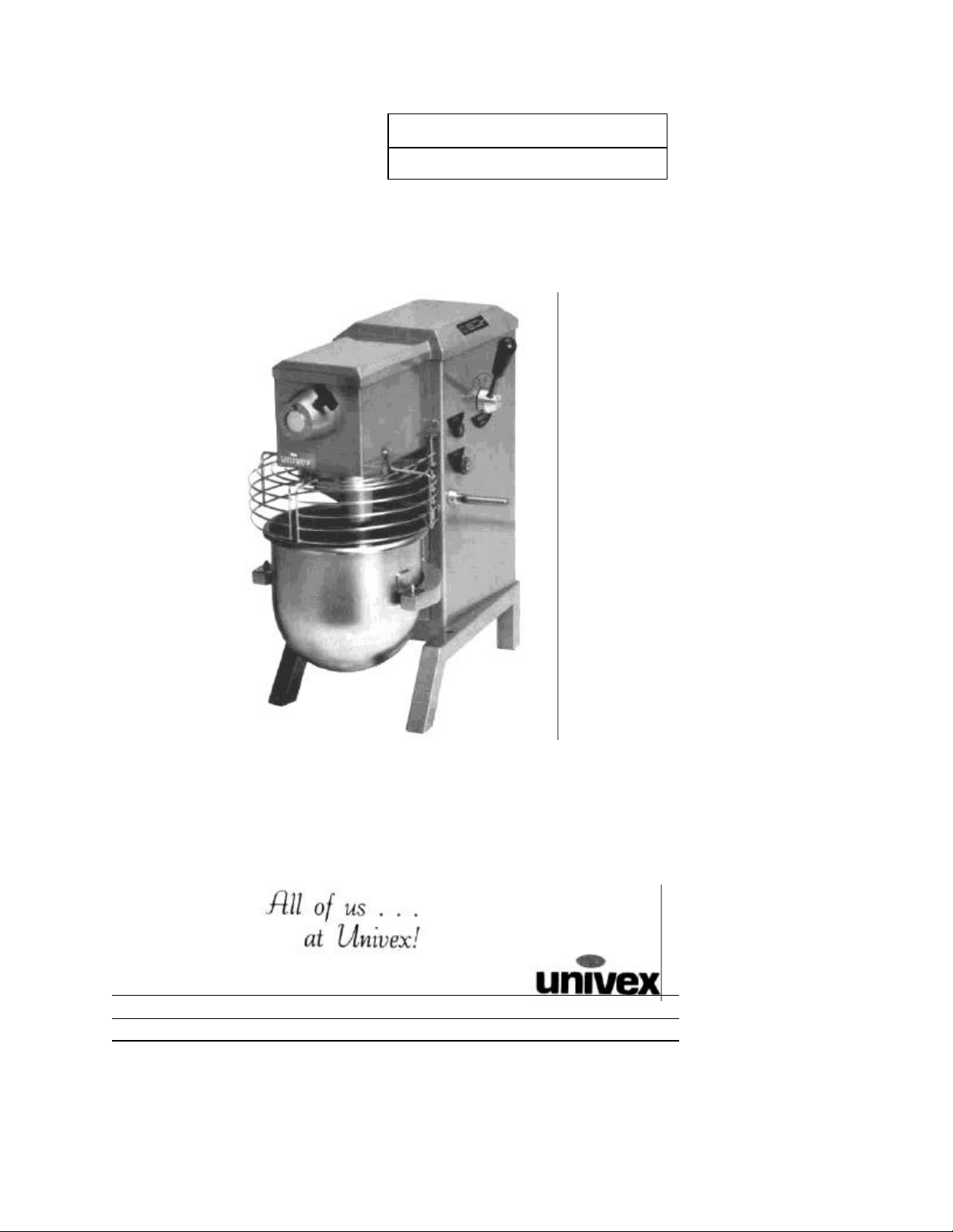
MECHANICS
MANUAL
SRM12
MAINTENANCE
SRM12
(SRM12 ) less hub
SRM12/298001 ED1
0011013
Page 2

TABLE OF CONTENTS
ILLUSTRATION
DESCRIPTION PAGE
TROUBLE SHOOTING GUIDE 3
REMOVAL OF TOP COVER 4
MECHANICS MAINTENANCE 4 - 5
REPAIR INSTRUCTIONS 6 - 10
REPLACEMENT PARTS, LISTS 11-22
WIRING DIAGRAMS 23 -25
LIST OF ILLUSTRATIONS
PAGE
FIGURE 1 OVERALL VIEW OF MIXER 2
FIGURE 2 LUBRICATION INSTRUCTIONS 5
FIGURE 3 TRANSMISSION 11
FIGURE 4 BEATER HEAD ASSEMBLY 12
FIGURE 5 POWER TAKE OFF ASSEMBLY 13
FIGURE 6 INPUT ASSEMBLY 14
FIGURE 7 VERTICAL SHAFT ASSEMBLY 15
FIGURE 8 BOWL LIFT ASSEMBLY 16
FIGURE 9 BOWL SUPPORT ASSEMBLY 17
FIGURE 10 SPEED CONTROL ASSEMBLY 18
FIGURE 11 VARI SPEED AND DRIVE SYSTEM 19 - 20
FIGURE 12 HOUSING ASSEMBLY 21 - 22
FIGURE 13 A WIRING DIAGRAM 115V, 208-230V. 60HZ, 1PH.
220-240V, 50HZ, 1PH , 100V, 50/60HZ, 1PH 23
FIGURE 13B WIRING DIAGRAM 115V, 60HZ, 1PH, CANADIAN ONLY
220-240V, 50HZ, 1PH, EUROPE ONLY 24
FIGURE 13C WIRING DIAGRAM 380-400V, 50HZ, 3PH EUROPE ONLY 25
Page 1
Page 3
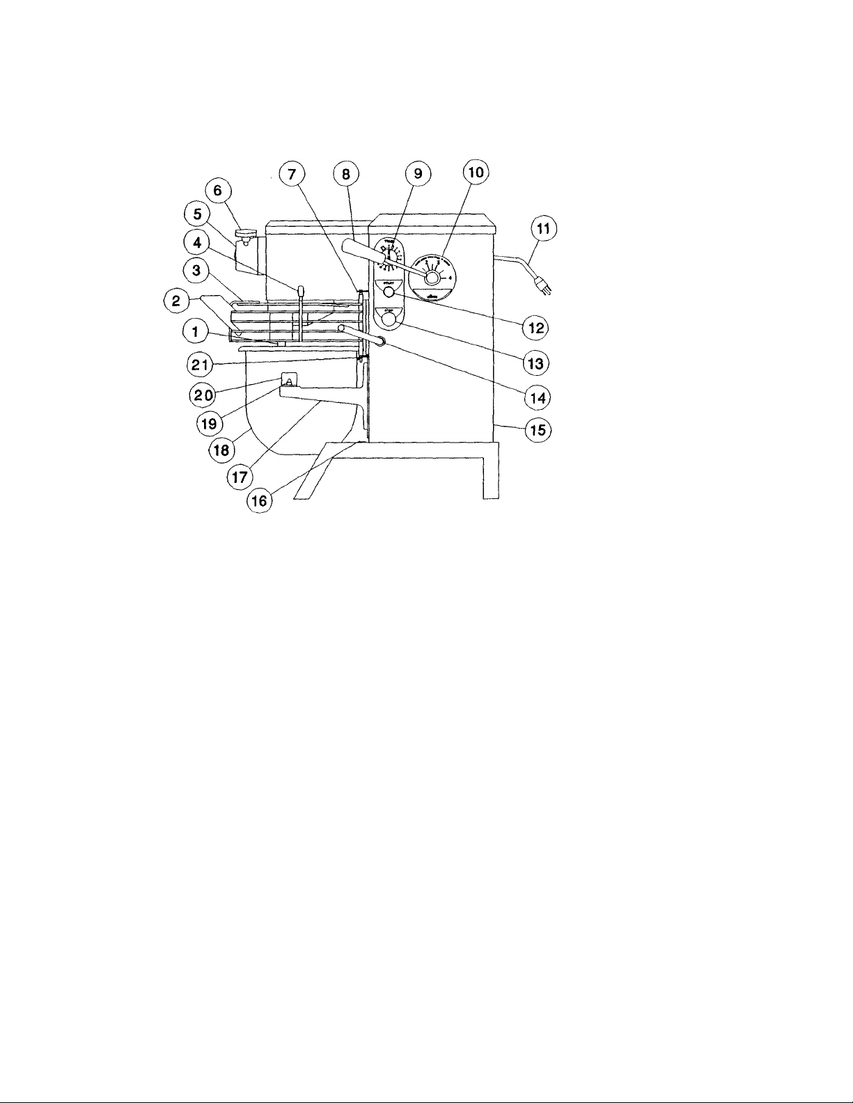
OVERALL VIEW OF FOOD MIXER
Figure 1
SRM12
1. BEATER SHAFT 12. START BUTTON
2. CHUTE 13. STOP BUTTON
3. SAFETY RING ASSEMBLY 14. BOWL LIFT HANDLE
4. MAGNET 15. REAR ACCESS PANEL
5. NO. 12 HUB 16. CAP (COVERS SHIPPING BOLT HOLE)
6. THUMB SCREW 17. BOWL SUPPORT
7. UPPER MOUNTING BRACKET 18. BOWL
8. SPEED CONTROL LEVER 19. BOWL SUPPORT PIN
9. TIMER (OPTIONAL) 20 BOWL MOUNTING BRACKET
10. SPEED INDICATOR LABEL 21. LOWER MOUNTING BRACKET
11. CORD
Page 2
Page 4
TROUBLESHOOTING GUIDE
to be repacked with
Badly worn or frayed drive belts
bowl per table of mixing
TROUBLE POSSIBLE CAUSE REMEDY
SRM12
1. Mixer will not
operate
2. Mixer runs but
beater will not turn
3. Slippage of agitator
during mixing
4. Speeds will not
change
1.1 Electrical service down
1.2 Burned switch contacts
1.3 Timer not turned on
1.4 Motor capacitor defective
1.5 Burned out motor
1.6 SAFETY RING not mounted
and closed
1.7 Bowl not raised
2.1 Speed changed while mixer
not running
2.2 Broken or slipping belt
2.3 Key or Pin sheared on input
shaft, input gear, bevel pinion,
vertical shaft or beater shaft
3.1 Loose belts
3.2 Mixer bowl is over-loaded
3.3 Speed is set too high for the
mix
4.1 Loose belts
4.2 Vari-speed pulley inoperable
1.1 Check electrical
service. Replace fuse
or reset circuit breaker
as necessary.
1.2 Replace.
1.3 Turn timer on.
1.4 Replace
1.5 Remove, test, repair or
replace.
1.6 Install SAFETY RING
ASSY
1.7 Raise bowl completely
2.1 While mixer is running,
move speed control
lever slowly forward
then back
2.2 Tighten or replace
2.3 Locate by step
inspection and replace
defective part.
3.1 Tighten belts.
3.2 Readjust contents of
bowl per table of
contents.
3.3 Shift speed lower till
action rotates smoothly.
4.1 Tighten or replace
4.2 Remove, clean and
lubricate or replace.
5. Attachments
contact bottom of
bowl
6. Excessive noise 6.1 Gears need
7. Difficulty in raising
or lowering bowl
5.1 Dented bowl
5.2 Insufficient clearance between
bottom of bowl and beater
5.3 Misalignment of transmission in
relation to bowl support
grease
6.2
6.3 Attachments hitting bowl
6.4 Overloaded mixing bowl
7.1 Lack of adequate lubricant on
bowl lift slide assembly and
housing
5.1 Remove dent or
replace bowl.
5.2 Readjust bowl lift
5.3 Realign transmission.
6.1 Locate source by
inspection and repack
with grease.
6.2 Replace belts.
6.3 Inspect for cause Ref:
5.1 and 5.2.
6.4 Readjust contents of
capacities.
7.1 Lubricate with grease
per Figure 2.
Page 3
Page 5

SRM12
REMOVAL OF TOP COVER
maintenance operations. It is secured by a spring clip at its front end and a screw
lift rear of cover, push
forward about
3
inches and lift cover off
b.
for overheating, noise and excessive end play. Replace if
qt. batter beater on
or
a. The top cover (Fig. 12 [12]) must be removed in order to perform the
at its rearward end. First, DISCONNECT THE ELECTRICAL POWER FOR
SAFETY. Then, remove the screw in the rear (Fig. 12 [20]),
b. Re-install in reverse procedure using care to insure that the cover sits squarely
Every six months a mechanic should perform the following inspection and maintenance as
required:
1. BELT
2 MOTOR
and uniformly on the mixer housing.
MECHANICS MAINTENANCE
a. WARNING: Start mixer and adjust speed control (Fig. 1 [8]) to speed 4. Stop
mixer. FOR SAFETY, DISCONNECT POWER.
Remove top cover (Fig. 12 [12]) and rear access panel (Fig. 12 [23]).
c. Check belt (Fig. 11 [2]). If broken, glazed or worn, replace.
d. Check belt (Fig. 11 [2]) for proper tension. The outer edge of the belt should be
flush with the outer diameter of the variable speed pulley (Fig. 11 [1]). If not,
adjust by loosening the jam nut (Fig. 11 [11]) and turning the connecting rod (Fig.
10 [14]) until the outer edge of belt is flush with the outer diameter of the pulley.
Retighten jam nut.
Check motor (Fig. 11 [19])
defective.
3 BOWL LIFT - ADJUSTMENT: (Fig. 8 and 9)
a. Place 12 qt. mixing bowl (Fig. 1 [18]) on bowl support and 12
beater shaft (Fig. 1 [1]).
b. Raise bowl support to the high position.
c. Check clearance between bottom of bowl and lowest point of batter beater.
Clearance should be 3/16 inch, plus or minus 1/16 inch.
d. If adjustment is required, disconnect power, loosen bolts (Fig. 9 [10]) and raise
lower bowl until desired clearance is obtained. Retighten bolts.
Page 4
Page 6
SRM12
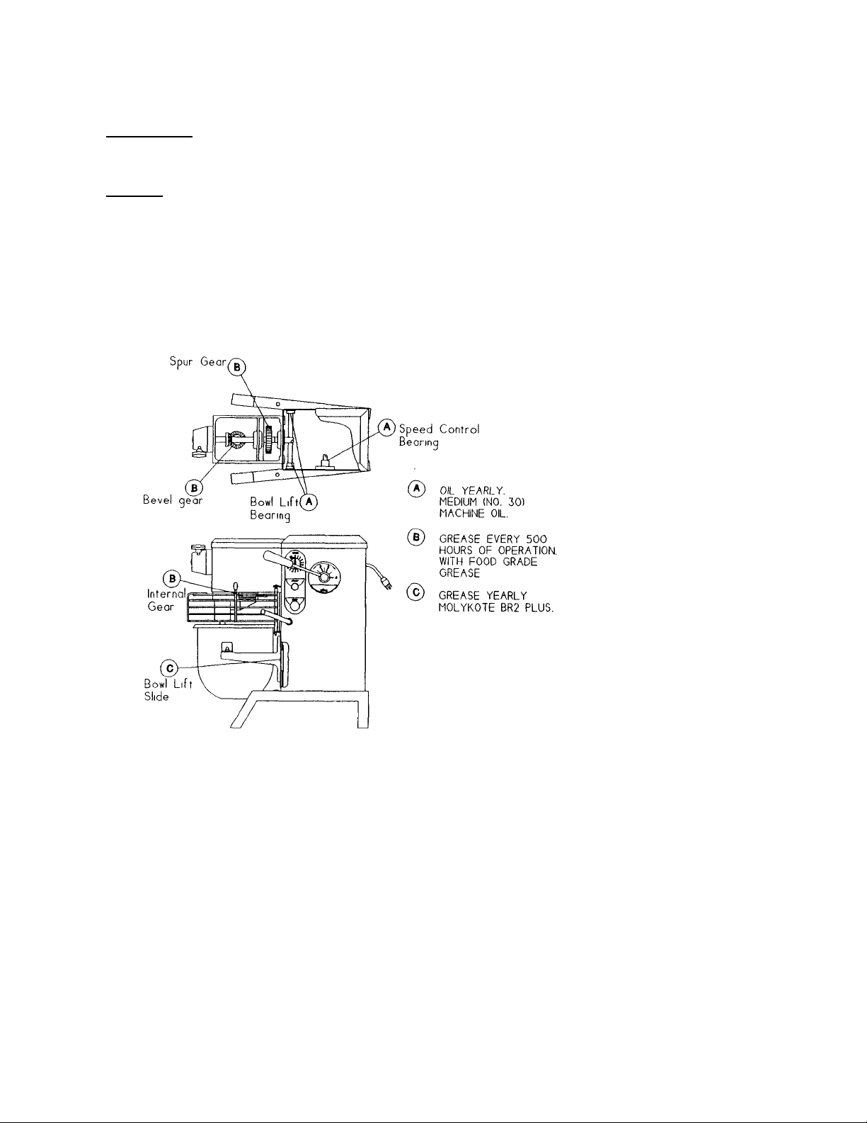
4 LUBRICATION
The lubrication instructions are in Fig. 2. The transmission and beater head gearing are
packed with Nevastane 5P7 grease. They must be re-packed every 500 hours of operation.
WARNING: NEVER WORK ON THE TRANSMISSION WITH THE MIXER RUNNING. IT IS
RECOMMENDED THAT THE ELECTRICAL SERVICE BE DISCONNECTED TO
PREVENT ACCIDENTAL START UP.
LUBRICATION INSTRUCTION
Figure 2
Page 5
Page 7

SRM12
REPAIR INSTRUCTIONS
Removal
1.
securing transmission housing to
retaining
bearing and gear
(including disassembly, replacement and reassembly.)
TRANSMISSION (Fig. 3)
Disassembly
WARNING: Disconnect power for safety.
2. Remove housing top cover (Fig. 12 [12]).
3. Adjust speed control to high speed; loosen belt retainer (Fig. 11 [14]), remove Vbelt (Fig. 11 [2]) from transmission drive pulley (Fig. 11 [3]). Remove drive pulley
and key (Fig. 11 [1]), loosen set screws on mounted bearing (Fig. 6 [8]).
4. CAUTION: Transmission assembly is heavy and must be supported prior to
removing. Remove four cap screws (Fig. 3 [10])
mixer housing. Remove transmission assembly and place on work bench.
5. Remove transmission cover (Fig. 3 [2]) by sliding towards the rear and lifting up-
6. Rotate gear train by hand and inspect for worn or chipped gears, bent shafts,
worn bearings and excessive backlash. Backlash measured at gear teeth
exceeding 1/32" is considered excessive. After trouble has been isolated,
proceed to disassemble.
1. Beater Head Assembly (Fig. 4)
Page 6
a. Remove cap screw (Fig. 4 [13]) and remove beater head assembly using
jacking screws (Fig. 4 [10]) if necessary. NOTE: Screw [13] has left handed
thread.
b. Remove drive pin (Fig. 4 [1]); top retaining ring (5); gear (6); key (3), bottom
retaining ring (5); retaining ring (7) and press shaft and bearings from housing
(11).
c. Press bearings (4 & 8) along with spacer (9) from shaft (2).
NOTE: If gear (Fig. 4 [ 6]) requires replacement, replace internal gear (Fig.
3 [13]) also.
2. Power Take Off Assembly (Fig. 5)
a. Remove three cap screws (Fig. 5 [8]), washers (6 & 7), deflector (5)
ring (3), gear (12) and withdraw assembly from housing.
b. Remove adapter (2), retaining ring (10) and press shaft (13)
assembly from housing (4).
c. Remove pin (17), gear (11), remaining rings (3), key (14) and press bearings
(9) from shaft (13).
NOTE: If gear (Fig. 5 [11]) requires replacement, replace gear (Fig. 7 [1])
also.
Page 8

SRM12
proved cleaning solvent.
If shafts have become slightly scored during the disassembly process, polish
e
Transmission should be progressively checked for smooth operation while on
Lubrication of the transmission should be done following its installation on the
evastane 5P7 grease to the spur gear and bevel gear meshes.
3. Input Assembly (Fig. 6)
a. Remove retaining ring (Fig. 6 [6]) and withdraw assembly from transmission.
b. Remove retaining ring (1), and press bearing (2) from shaft (7) .
c. Remove retaining rings (3) and slide gear (4) from shaft (7).
d. Remove Woodruff key (13) and press bearing (5) from shaft (7).
NOTE: If gear (Fig. 6 [4]) requires replacement, replace gear (Fig. 5 [12])
4. Vertical Shaft Assembly (Fig 7)
a. Remove key (4).
b. Invert housing on suitable support and press shaft (2) from transmission
Reassembly
housing (Fig. 3 [1]).
c. Remove lower bearing (5) with puller and remove spacer (7).
d. Remove retaining ring (6) and pull or press upper bearing (5) from
transmission housing (Fig. 3 [1]).
e. Remove pin (3) and press shaft (2) from gear (1).
a. Clean all components except bearings with safety ap
Inspect components for defects and replace those found to be defective.
NOTE: All gears should be replaced as sets.
also.
b.
the shafts with fine machinist crocus cloth. Use care to avoid excessive
removal of shaft surface or proper fit of components will be lost.
c. Reassembly should be carried out in the reverse of the disassembly
procedures stated above. Successful reassembly is very dependent on th
cleanliness of all surfaces particularly the bores of housings, gears and
bearings as well as the outer surface of shafts. It is well to recheck each
component for cleanliness as it is picked up for reassembly. New keys and
roll pins should be used on reassembly.
d.
the workbench by hand turning each assembly as it is installed.
e.
mixer. Apply N
This may be simplified by feeding the grease into the rotating gear meshes.
Caution should be exercised to avoid entrapment of the application
implement in the gear teeth. Insure the deflector (Fig. 5 [5]) is positioned to
dynamically guide the lubrication into the bevel gear mesh.
Page 7
Page 9

SRM12
Bowl Lift Assembly (Fig. 8 and 9)
Plastic shims may exist between bowl support and gibbs. Left rail is
h.
k.
per Mechanics Maintenance
Loosen set
a.
WARNING;
Disconnect electrical power for safety.
b. Remove housing top cover (Fig. 12 [12]) and rear access panel (Fig. 12 [23]).
c. Remove two cap screws (Fig. 9 [10]). Remove four cap screws (Fig. 9 [11]),
remove bowl support (Fig. 9 [1]) and slide cover (Fig. 9 [3]) and gibbs (Fig. 9
[7]). Remove six Kep nuts (Fig. 12 [38]) and remove rails (Fig. 12 [40]).
CAUTION: Bowl support must be supported while screws are being
removed in order to prevent it from falling.
NOTE:
to be adjusted for snug fit to bowl support when reassembling.
d. Remove fixed slide cover (Fig. 12 [41]) by removing two nuts (Fig. 12 (10))
e. Remove retaining ring (Fig. 8 [9]) from cam pin. Slide link (Fig. 8 [10]) from
cam pin.
f. Remove screw (Fig. 8 [11]) and loosen collar set screw [7] and pull lever [1]
from housing.
g. Remove four nuts (Fig. 8 [6]) and lift off bearings [4].
Clean and inspect sliding surfaces for excessive wear.
i. Replace parts showing excessive wear.
j Lubricate sliding surfaces with grease.
Reassemble and reinstall in the reverse of the above procedure.
l. Check clearance between batter beater and bowl
paragraph 4. a - d and readjust as necessary.
SPEED CONTROL ASSY. (Fig. 10)
Disassembly
1. Remove housing cover (Fig. 12 [12]) and rear access panel (Fig. 12 [23]).
2 Remove retaining ring (16). Remove rod end (15) from cam assembly (11).
screws (10) in cam assembly (11).
3 Drive roll pin (4) from hub (3) and pull hub (3), lever (2), and handle (1) from cam
assembly shaft (11). Remove washer (5) from cam assembly (11).
4. Unscrew hub (3) and handle (1) from lever (2).
5. Remove nut (8) and washer (7) from studs holding speed control bearing (6) to
housing (Fig. 12 [1]).
Page 8
Page 10

SRM12
and
10
6. Withdraw bearing (6) and remaining assembly from housing (Fig. 12 [1]).
7. Pull cam assembly (11) from bearing (6).
8. Remove screws (18), lock washers (19), strap (20), and spring (17) from bearing (6).
9. Remove screws (13) and detent disk (12).
Reassemble
10. Reassemble in reverse of above procedure. Grease cam assembly shaft (11) and
detent disk (12) during assembly with MolyKote BR2 Plus or general purpose
bearing grease. Adjust belt as described in Mechanics Maintenance section 1:
paragraph a, d - f.
11. If speed control handle (1) moves while the mixer is running, tighten set screws (10)
against spring washer (9) until movement stops.
VARI-SPEED ASSEMBLY (Fig 11)
Disassembly
1. Remove housing cover (Fig. 12 [12]) and rear access panel (Fig. 12 [23]) as
described in the removal of the top cover section.
2. With mixer off and in low speed shift to high speed. Remove nut (5), washer (6)
belt retainer (4) from housing.
3. Unwrap belt (2) from driven pulley (3) and pull from vair-speed pulley (1).
4. Loosen set screw on pulley (3) and remove from shaft.
5. Loosen power lead connections of motor cord (22) at the contactor or starter.
Remove ground lug from housing. Remove nuts (15), washers (14) and cord clamps
(13) securing motor cord (22) to mixer housing.
6. Loosen jam nut (11) and unscrew connecting rod (Fig. 10 [14]).
7. Remove nuts (5), washers (6), straps (20) and rails (21).
8. Rotate motor (19) and mount (8) so that motor shaft is pointing up. Next rotate motor
assy. 90° and remove through rear of housing.
9. Remove connection box plate on end of motor. Remove motor cord (22) leads.
Loosen set screws securing pulley (1) to motor shaft. Slide pulley from motor shaft.
Remove nuts (5), washers (6) and remove motor (19) from mount (8).
Page 9
Page 11

SRM12
unt and tighten with
For the remaining parts which have not been discussed pertain to electrical components
Reassemble
Reassemble in reverse of above procedure. The following guidelines should be
observed.
1. Be sure motor rotation and voltage has been checked when a new motor in being
installed.
2. Grease all sliding surfaces of motor slide assy. .
3. Be sure motor mount (8) fits tightly between rails (21). First tighten the rail (21) and
strap (20) closest to the front of the mixer housing. With mount assembly held firmly
against rail (21) install and adjust second rail and strap against mo
washers (6) and nuts (5).
4. Adjust belt tension per procedure described in mechanics maintenance 1.d.
HOUSING (Fig 12)
and the housing. Figures 12, 13A, 13B and 13C should provide adequate guidance for
the disassembling and reassembling of these parts.
Page 10
Page 12

SRM12
TRANSMISSION
Figure 3
ILLUS NO. PART NO. DESCRIPTION QTY.
1. 1012440 Transmission Housing 1
2. 1012017 Transmission Cover 1
3. 1200012 Screw, Phillips HD, 10-32 x 1/2" 6
4. 1024041 Spring 1
5. 4400065 Washer, Split Lock #10 6
6. 1200076 Washer, Flat #10 6
7. 8800022 Foam Strip 1
8. 1200084 Washer, Steel Flat 1/2 4
9. 1200085 Lock Washer, Split 1/2 4
10. 1200057 Screw, Hex HD Cap 1/2-20 x 1" 4
11. 4400194 Pin dowel 1
12. 1200440 Screw, Soc Hex Hd Cap 10-32 x 1" 4
13. 1012116 Gear, Internal 1
14. 4400341 Label, Univex 1
15. 1012439 Magnet 2
16. 1012438 Holder, Magnet 2
Page 11
Page 13

SRM12
BEATER HEAD ASSEMBLY
1
1
1
1
1
1
1
1
1
1
1
1
ILLUS NO. PART NO. DESCRIPTION QTY.
1. 1200109 Pin, Drive 1/4" x 1
2. 1012107 Shaft, Beater Head
3. 1200113 Key, Woodruff #9
4. 1012167 Ball Bearing
5. 1200120 Retaining Ring, External 3
6. 1012114 Gear, Beater Head, Pinion Only
7. 1200118 Retaining Ring, Internal
8. 1012166 Ball Bearing
9. 1012110 Spacer, Beater Head
10 8900038 Set Screw 3/8-16 x 1 1/4 2
11. 8800041 Beater Head
12. 4400499 Washer 7/16
13. 1200051 Screw, Hex Hd Cap 3/8-24 x 1 1/4" L.H.
14. 1020002 Ring, Splash
15. 4400269 Label, Rotation 1
Figure 4
Page 12
Page 14

SRM12
POWER TAKE OFF ASSEMBLY
Figure 5
ILLUS. NO. PART NO. DESCRIPTION QTY.
1. 8800033 Cover, With P.T.O. 1
2. 8800012 Adaptor, With P.T.O. 1
3. 1200119 Retaining Ring, External 5
4. 4400025 Housing, With P.T.O. 1
1012428 Housing, Without PTO 1
5. 1024417 Deflector, Lubrication 1
6. 4400005 Lockwasher 1/4 3
7. 1200075 Washer, Flat 1/4 1
8. 1200025H Screw, Hex HD Cap 1/4-20 x 3/4" 3
9. 1030019 Ball Bearing 2
10. 1200117 Retaining Ring Internal 1
11. 1012309 Gear, Bevel, Pinion Only 1
12. 1020004 Gear, Spur 1
13. 1012320 Shaft, With P.T.O. 1
1012429 Shaft, Without P.T.O 1
14. 1200113 Woodruff Key #9 1
15. * 4400006 Spring, Shaft With P.T.O. 1
16. * 4400016 Ball, Shaft With P.T.O, 1
17. 1200103 Roll Pin, 5/16" x 1 1/4 1
18. 4400229 Knob, With P.T.O. 1
19. 4400210 Washer, With P.T.O. 1
20. 8900019 Screw, SFHD 6-32 X 3/8 With P.T.O. 2
* NOT AVAILABLE, PART OF SHAFT ILLUS. NO. 13
Page 13
Page 15

SRM12
INPUT ASSEMBLY
1
1
3
1
1
1
1
1
Figure 6
ILLUS. NO. PART NO. DESCRIPTION QTY.
1. 1200120 Retaining Ring
2. 1012166 Ball Bearing
3. 1200119 Retaining Ring, External
4. 1020010 Gear, Spur Input, Pinion Only
5. 1030019 Ball Bearing
6. 1200117 Retaining Ring, Internal
7. 1012322 Input Shaft
8. 1012306 Ball Bearing, Flange
9. 1200025H Screw, Hex Hd 1/4-20 x 3/4 2
10. 1200075 Washer, 1/4 2
11. 4400141 Nut, Kep 1/4-20 2
12. 4400230 Key - 3/16" sq x 1 1/2" Lg. 1
13. 1200113 Woodruff Key #9 1
Page 14
Page 16

SRM12
VERTICAL SHAFT ASSEMBLY
Figure 7
LLUS NO. PART NO. DESCRIPTION QTT.
1. 1012311 Bevel Gear 1
2. 1012434 Shaft, Vertical 1
3. 4400022 Roll Pin 5/16" x 1 1/2" 1
4. 1200113 Key, Woodruff 1
5. 1030019 Ball Bearing 2
6. 1200117 Retaining Ring, Int ernal 1
7. 8800042 Spacer, Vertical 1
Page 15
Page 17

SRM12
BOWL LIFT ASSEMBLY
Figure 8
ILLUS. NO. PART NO. DESCRIPTION QTY.
1. 1012348 Lever, Bowl Lift 1
2. 1024406 Hub, Bowl Lift I
3. 1200301 Nylon Washer, 5/8 1
4. 1012304 Bearing, Flange 2
5. 4400065 Lockwasher, Split #10 4
6. 1200060 Nut, Hex 10-32 4
7. 1012305 Collar, Shaft 1
8. 1012317 Cam, Bowl Lift 1
9. 1200121 Retaining Ring 1
10. 1012352 Link, Connector 1
11. 1200425 Screw, Flat Hd 1/4-20 x 1 1
12. 4400118 Roll pin 3/16 x 1" 1
13. 1200076 Washer, Flat #10 4
Page 16
Page 18

SRM12
BOWL SUPPORT ASSEMBLY
Figure 9
ILLUS NO. PART NO. DESCRIPTION QTY.
1. 1012432 Support, Bowl 1
2. 4400219 Pin, Bowl Support 2
3. 1012431 Cover, Moveable Slide 1
4. 1012430 Yoke 1
5. 1012243 Pin, Yoke 1
6. 1200121 Retaining Ring 2
7. 1012422 Gibb, Bowl Lift 2
8. 1200075 Washer, 1/4 2
9. 4400005 Lock Washer, 1/4 2
10. 4400155 Screw, Hex Cap 1/4-20 x 1/2 2
11. 1200039 Screw, Hex Hd 5/16-18 x 3/4 4
12. 1200077 Lockwasher, 5/16 4
13. 4400278 Rubber Strip 10 3/4 Lg 2
Page 17
Page 19

SRM12
1
1
1
1
SPEED CONTROL ASSEMBLY
Figure 10
ILLUS. NO. PART NO. DESCRIPTION QTY.
1 4400202 Handle 1
2 1020066 Lever, S.C.
3 1012137 Hub, S.C.
4 1200300 Roll Pin 3/16" x 2"
5 1200301 Nylon Washer 5/8 1
6 1020068 Speed Control Bearing
7 4400127 Steel Flat Washer 3/8 2
8 1200063 Kep Nut 5/16-18 2
9 1200156 Spring Washer 5/8 2
10 1200304 Set Screw 10-32 x 3/4" 2
11 1012359 Cam, S.C. 1
12 1023222 Detent Disc 1
13 1200012 Phillips Hd. Screw 10-32 x 1/2" 2
14 1012329 Connecting Rod, S.C. 1
15 1012202 Rod End 3/8-24 L.H. 1
16 1200121 Retaining Ring 2
17 1023223 Spring, S.C. 1
18 4400208 Phillips Pan Hd. Screw 1/4-20 x 1/2" 2
19 4400005 Lock Washer 1/4 2
20 1023225 Strap, S.C. 1
Page 18
Page 20

SRM12
1
1
1
VARI-SPEED AND DRIVE SYSTEM
Figure 11
ILLUS. NO. PART NO. DESCRIPTION QTY.
1. 1012373 Pulley, Vari-Speed 1
2. 1012357 Belt, Cogged 1
3. 1020500 Pulley. Driven 1
4. 1023240 Retainer, Belt 1
5. 1200063 Nut, Kep 5/16-18 9
6. 4400127 Washer 3/8 9
7. 1200039 Screw, Hex Hd Cap 5/16-18 x 3/4 4
8. 1012346 Mount, Motor
9. 1200388 Nut, Hex Elastic Stop 3/8-16 1
10. 1012201 Rod End R H
11. 1200155 Nut, Hex 3/8-24
12. 1200359 Screw, Hex Hd Cap 3/8-16 x 1 '/2 1
13. 4400101 Clamp, Cord 3
14. 1200076 Washer #10 3
15. 1200060 Nut, Hex 10-32 4
16. 4400065 Lock Washer #10 2
17 7100107 Strain Relief 1
18 8800200 Cord, Electric 115V, 60HZ, 1PH,
100V, 50/60HZ, 1PH 1
8800201 Cord, Electric 230V, 60HZ, 1PH,
220-240V, 50HZ, 1PH 1
8800101 Cord, Electric, 230V, 50HZ, 1PH (BRITISH) 1
8800102 Cord, Electric 230V, 50HZ, IPh (CE) 1
7100100 Cord, Electric, 400V, 50HZ, 3PH (CE)
400V,60HZ,3PH 1
19. 1012361 Motor 1/3HP, 115V, 60HZ, 1PH 1
6090012 Motor 1/3HP, 100/230V, 50/60HZ, 1PH 1
1012362 Motor 1/3HP, 380V, 50HZ, 3PH, 480V, 60HZ, 3PH 1
20. 1012355 Strap, Motor Slide 2
21. 1012356 Rails, Motor Slide 2
22. 8800202 Cord, Motor, 1PH 1
8800226 Cord, Motor, 3PH 1
Page 19
Page 21

SRM12
VARI-SPEED AND DRIVE SYSTEM
Figure 11
Page 20
Page 22

HOUSING ASSEMBLY
1
1
1
1
1
ILLUS. NO. PART NO. DESCRIPTION QTY.
1 1012437 Mixer Housing 1
2 7100123 Switch, Guard 1
3 4400413 Bolt, Can 1/4-20 X 3/4 SS, 4
4 4400003 Spacer 4
5 1012441 Bracket, Upper 2
6 4400141 Nut, Kep, 1/2-20 4
7 7100011 Contactor, 115V, 60HZ, 1PH 1
7100015 Contactor, 100V,50/60HZ, 1PH 1
7100012 Contactor, 220.240,230V, 50-60HZ, 1PH 1
7100109 Starter, 220-240V, 50HZ, 1PH (Europe Only) 1
7100040 Starter, 115V, 60HZ, 1PH (Canadian Only) 1
7100119 Starter, 380V , 50HZ, 3PH (Europe Only) 1
8 4400065 Lockwasher, #10 4
9 1200076 Washer, Steel Flat #10 10
10 1200060 Hex Nut 10-32 10
11 7100010 Mount, Contactor 1
12 1012327 Cover, Housing 1
13 4400114 Decal, Cover Removal (Not For Europe) 1
14 4400113 Decal, Stop Unplug (Not For Europe) 1
15 1200092 Washer Flat #8 2
16 4400183 Washer Lock #8 2
17 1200008 Screw 8-32 x 3/8" PPHD 2
18 1024042 Spring
19 4400001 Nut, Tinnerman
20 1200422 Screw, sheet metal #12 PPHD 1" LG.
1200451 Screw (Security opt ion)
21 1012411 Bracket, Bowl Lift Switch
22 7100023 Insulation Barrier 3
23 1012374 Panel, Rear Access 1
24 8800022 Foam Strip 7.5"
25 1200012 Screw, Phillips Hd 10-32 x 1/2" 6
1200452 Screw (Security Option) 6
26 1200432 Screw, Hex HD 4.40 x 3/4 2
27 1200433 Nut, Elastic Stop 4-40 2
28 7100103 Switch, Guard 1
29 4400312 Decal, Speed Control 1
30 4400310 Decal, Start/Stop (Without Timer) 1
4400311 Decal, Start/Stop Timer (Optional) 1
31 7100101 Push Button, Start 1
32 7100102 Push Button, Stop 1
33 1012427 Screening 1
34 1012442 Bracket, Lower 2
35 1200125 Cap 4
36 4400037 Feet 4
37 4400194 Dowel Pin 1/4 x 1/2LG 2
38 1200063 Nut, Kep 5/16-18 6
39 4400127 Washer, Flat 3/8 6
40 1012423 Rail, Bowl lift 2
41 1012443 Cover, Fixed Slide 1
42 4400079 Screw, Chz HD M4-.7mm x 6mm LG (Optional) 2
43 7100028 Knob, Timer (Optional) 1
44 7100027 Timer, 15min (Optional) 1
Page 21
SRM12
Page 23

SRM12
45 4400335 Label, Ground (Not Shown) 1
46 1033326 Transformer (Europe Only) (Not Shown) 1
47 1200450 Tool Kit (Security Option) 1
HOUSING ASSEMBLY
Figure 12
Page 22
Page 24

115V, 60HZ, 1PH, 220-240V, 50HZ, 1PH, 230V, 60HZ, 1PH 100V,
ELECTRICAL WIRING DIAGRAM
50/60HZ, 1PH Figure 13A
WIRE TABLE
PART
NUMBER
TIMER ONLY W2 16 3 13 2 2 RED
8800234
8800202 W11 CORD
WIRE NO. GA
W1 16 3 13 1 2 WHITE
W3 16 3 6 2 2 BLACK
W4 16 3 6 2 2 WHITE
W5 16 3 2 1/2 1 2 RED
W6 16 3 2 1/2 1
W7 16 3 19 1
W8 16 3 2 1 1
W9 16 3 2 1/2 1
W10 16 3 2 1 /2 1
SEE
NOTE
LENGTH
IN INCHES
END A
SEE NOTE
NOTES: I. ATTACH DOUBLE CRIMP FERRULE.
2. ATTACH DOUBLE CRIMP 1/4- FEMALE QUICK DISCONNECT
FULLY INSULATED.
3. MATERIAL: 1015 TEW CSA AND UL APPROVED.
END B
SEE
NOTE
1
1
1
1
1
SRM12
COLOR
RED
BLACK
RED
RED
RED
IMPORTANT: Before making electrical connections, check the specifications on the data plate
(located on the rear access panel) to assure they agree with those of your electrical service.
WARNING: Whenever maintenance is being performed or whenever the top cover or rear access
panel have been removed, DISCONNECT electrical cord and place a tag on it indicating the mixer is
being worked on
Page 23
Page 25

ELECTRICAL WIRING DIAGRAM
INCHES
NOTE
NOTE
W6 16 3 2 1/2 RED
W8 16 3 21 RED
W10 16 3 5 1/2 RED W1
1 12 3 10 RED
W12 12 3 10 BLACK
NOTES
115V, 60HZ, 1PH, FOR CANADIAN ONLY
220-240V, 50HZ, 1PH, FOR EUROPE ONLY
Figure 13B
SRM12
WIRE TABLE
LENGTH
PART
NUMBER
TIMER ONLY W2 16 3 13 2 2 RED
8800234
PART OF
STARTER
8800202 W13 CORD
WIRE NO. GA
W1 16 3 13 1 2 WHITE
W3 16 3 6 2 2 BLACK
W4 16 3 6 2 2 WHITE
W5 16 3 2 1/2
W7 16 3 19
W9 16 3 4 1/2
SEE
NOTE
END A
END B
IN
SEE
SEE
2 RED
COLOR
BLACK
RED
1. ATTACH DOUBLE CRIMP FERRULE.
2. ATTACH DOUBLE CRIMP 1/4- FEMALE QUICK DISCONNECT FULLY INSULATED.
3. MATERIAL; 1015 TEW CSA AND UL APPROVED.
IMPORTANT: Before making electrical connections, check the specifications on the data plate
(located on the rear access panel) to assure they agree with those of your electrical service.
WARNING: Whenever maintenance is being performed or whenever the top cover or rear access
panel have been removed, DISCONNECT electrical cord and place a tag on it indicating the mixer is
being worked on
Page 24
Page 26

ELECTRICAL WIRING DIAGRAM
380-400V, 50HZ, 3PH, FOR EUROPE ONLY
Figure 13C
POWER IN W13
SRM12
WIRE TABLE
PART
NUMBER
TIMER ONLY
8800234
STARTER
NOTES: 1. ATTACH DOUBLE CRIMP FERRULE.
8800226 W14 CORD
2. ATTACH DOUBLE CRIMP 1/4" FEMALE QUICK DISCONNECT FULLY INSULATED.
3. MATERIAL: 1015 TEW CSA AND UL APPROVED.
4. ATTACH #10 RING TERMINAL
WIRE NO. GA
WIA 16 3 22 2 4 WHITE
W2 16 3 13 2 2 RED
W1 16 3 4 1 /2 1 2 WHITE
W3 16 3 6 2 2 BLACK
W4 16 3 6 2 2 WHITE
W5 16 3 2 1 /2 1 2 RED
W6 16 3 2 1/2 1 1 RED
W7 16 3 19 1 1 BLACK
W8 16 3 21 1 1 RED
W9 16 3 4 1/2 1 1 RED PART OF
W10 16 3 5 1/2 1 1 RED
W1 1 16 3 7 1 4 RED
W12 16 3 9 1 4 RED
W13 16 3 9 1 4 RED
SEE
NOTE
LENGTH
INCHES
END A
IN
NOTE
SEE
END B
SEE
NOTE
COLOR
IMPORTANT: Before making electrical connections, check the specifications on the data plate
(located on the rear access panel) to assure they agree with those of your electrical service.
WARNING: Whenever maintenance is being performed or whenever the t op cover or rear access
panel have been removed, DISCONNECT electrical cord and place a tag on it indicating the mixer is
being worked on.
Page 25
 Loading...