


X-600 / X2-600
Laser Engraving and Cutting System
Safety, Installation, Operation,
and Basic Maintenance Manual
Universal Laser Systems, Inc.
16008 North 81st Street
Scottsdale, AZ 85260 USA
Customer Support Department
Phone: 480-609-0297
Fax: 480-609-1203
Web Based Email Support: www.ulsinc.com
August 2001
Notice
This publication and its contents are proprietary to Universal Laser Systems, Inc. (ULS), and are intended solely for the contractual use of ULS, Inc. customers.
While reasonable efforts have been made to assure the accuracy of this manual, ULS shall not be liable for errors contained herein or for incidental or consequential damage in connection with the furnishing, performance, or use of this material.
ULS reserves the right to revise this manual and make changes from time to time without obligation by ULS to notify any person of such revision or changes.
ULS does not assume any liability arising out of the application or use of any products, circuits, or software described herein. Neither does it convey a license under its patent rights nor the patent rights of others.
This publication and its contents may not be reproduced, copied, transmitted, or distributed in any form, or by any means, radio, electronic, mechanical, photocopying, scanning, facsimile, or otherwise, or for any other purpose, without the prior written permission of ULS.
ULS provides no warranties whatsoever on any software used in connection with any ULS Laser Platform, express or implied. Neither does it guarantee software compatibility with any off-the-shelf software package or any software program that has not been written by ULS.
Intended use of this system must be followed within the guidelines of this manual. In no event will ULS be liable for any damages caused, in whole or in part, by customer, or for any economic loss, physical injury, lost revenue, lost profits, lost savings or other indirect, incidental, special or consequential damages incurred by any person, even if ULS has been advised of the possibility of such damages or claims.
HP is a registered trademark of Hewlett-Packard Corporation.
Windows is a registered trademark of Microsoft Corporation.
Macintosh is a registered trademark of Apple Computer Corporation.
PostScript, Photoshop, and Streamline are registered trademarks of Adobe Systems Inc.
CorelDraw is a registered trademark of Corel Corporation.
AutoCad is a registered trademark of Autodesk Inc.
© Universal Laser Systems Inc., 2001
All Rights Reserved
Introduction
We would like to thank you for purchasing the X-600 or X2-600 Laser Platform. Years of testing and refinements have made this unit the ultimate laser engraving and cutting system. With it’s small footprint design and the oversized 32” x 18” work area, the X-600 Laser Platform is now equipped with our unique
“Rapid Reconfiguration Capability ” and the X2-600 has the capability of adding an additional Laser Cartridge for that “extra” laser power when needed. This gives the user the ability to exchange it’s “Quick Change Laser Cartridge “ with a lower or higher powered unit in minutes and without the use of tools. This feature and many others make this unit truly the most flexible, easiest to use, and the most user serviceable and configurable laser system in the world.
To begin with, we highly recommend that this entire manual be read before attempting to use your Laser Platform. The manual includes important information about safety, assembly, use, and maintenance. We cannot emphasize the importance of reading this ENTIRE manual.
How To Get Help
Step 1:
Determine exactly what the problem is. Refer to the Troubleshooting Guide at the end of this manual for a possible solution.
Step 2:
Try to recreate the problem and write down the circumstances in which the problem occurred. Try to recall if the problem began all of a sudden, worsened over time, or began after you performed any recent maintenance. Also be prepared to describe all pertinent information about the computer being used such as software, operating system and computer type. Have the serial number of the laser system available. The serial number tags are located on the back of the machine, next to the exhaust port, and inside the front door, visible when you open it.
Step 3:
Contact your local Sales Representative first to assist you in diagnosing the problem. If possible, call from a phone that is close to the laser so that the system can be operated while talking to our representative.
Step 4:
If you still cannot resolve the problem, use your Internet web browser and log on to our website: www.ulsinc.com. Click on the “Technical Support “ link. Then click on the “Technical Support Request Form” and follow the instructions.
Step 5:
If you are unable to obtain Internet access, contact our Customer Service Department at:
Universal Laser Systems, Inc.
Customer Support Department
16008 North 81st Street
Scottsdale, AZ 85260
Phone: 480-609-0297
Fax: 480-609-1203
M-F 7am – 6pm Arizona Time
|
Specifications |
Model Number |
X-600 or X2-600 |
Resolution |
1000 x 1000 DPI, 500 x 500 DPI, 333 x 333 DPI, 250 x 250 DPI |
|
200 x 200 DPI, Draft |
Computer Needed |
Windows 95 or 98, PC compatible |
Work Area |
32” x 18” (812.8 mm x 457.2 mm) |
Table Size |
37” x 23” (939.8 mm x 584.2 mm) |
Maximum Part Size |
37” (939.8 mm) wide x 23” (584.2 mm) deep x 9” (228.6mm) tall |
Laser Source(s) |
15, 20, 25, 30, 35, 40, 45, 50 Quick Change Laser Cartridge |
(X2-600 only) |
15, 20, 25, 30, 35, 40, 45, 50 Quick Change Laser Cartridge (Laser #2) |
Lenses Available |
Focal Length / Spot Size / (Standard or Optional) |
|
1.5” (38.1mm) / 0.003 inches (.08 mm) / Optional |
|
2.0” (50.8mm) / 0.005 inches (.13mm) / Standard |
|
2.5” (63.5mm) / 0.007 inches (.18 mm) / Optional |
|
4.0” (101.6mm) / 0.013 inches (.33 mm) / Optional |
Interfaces |
Centronics parallel, RS232C Serial |
Memory Buffer |
Multiple and Single file storage modes, automatic data compression |
Dimensions |
38” high x 44” wide x 38” deep (965 x 1117 x 965mm) |
Weight |
approximately 320 lbs. (145 kg) |
Safety |
CO2 interlocked safety enclosure = Class I |
|
Red Pointer Diode = Class IIIa |
Available Options |
Rotary Fixture, Air Assist, Honeycomb Cutting Table |
Facility Requirements
Power (X-600) |
Single Phase 110/220V AC, 15/8 Amp, 50/60 Hz |
(X2-600) |
Single Phase 220V AC, 8 Amp, 50/60 Hz |
Exhaust |
Outside exhausting required, two 4” connections, |
|
500 CFM minimum (250 at each connection) at 6 inches static pressure |
|
(425m3/hr at 1.5kPa) |
Cooling |
Air-cooled (ambient temperature 50ºF (10ºC) to 95ºF (35º C)) |
Specifications are subject to change without notice.

Table of Contents
SECTION 1 - Safety
Description of Appropriate Use .............................................................................................
General Safety ......................................................................................................................
Laser Safety ..........................................................................................................................
Safety Labels ........................................................................................................................
Safety Label Locations..........................................................................................................
EU Compliance (CE).............................................................................................................
FCC Compliance ...................................................................................................................
SECTION 2 - Installation
Operating Environment Requirements..................................................................................
Electrical Requirements ........................................................................................................
Exhaust Requirements..........................................................................................................
Passing Through a Narrow Doorway ....................................................................................
Leveling the System..............................................................................................................
Computer Requirements .......................................................................................................
Software Suggestions ...........................................................................................................
Printer Driver Installation.......................................................................................................
Laser Cartridge Installation ...................................................................................................
Finalizing the Connections ....................................................................................................
Computer Controlling the Laser System ...............................................................................
SECTION 3 - System Operation
How it Works .........................................................................................................................
Powering ON the Laser System............................................................................................
The Control Panel .................................................................................................................
The Menu System .................................................................................................................
Creating the Graphic .............................................................................................................
Loading and Positioning the Material....................................................................................
Focusing the Laser Beam .....................................................................................................
Printing to the Laser System .................................................................................................
Starting the Laser Engraving or Cutting Process..................................................................
Material Removal and Reloading ..........................................................................................
SECTION 4 - Basic Maintenance
Cleaning and Maintenance Supplies ....................................................................................
Motion System Components Diagram ..................................................................................
System Cleaning ...................................................................................................................
Optics Cleaning .....................................................................................................................
Exhaust Plenum Cleaning.....................................................................................................
Adjustments and Lubrication.................................................................................................
Electronic Upgrading.............................................................................................................
Battery Replacement.............................................................................................................
Cooling Fan Filters ................................................................................................................
Maintenance Schedule..........................................................................................................
Troubleshooting ....................................................................................................................
SECTION 5 - Sample Materials
Safety ....................................................................................................................................
Materials................................................................................................................................
Acrylic - Cast and Extruded ..................................................................................................
Acrylic - Mirrored ...................................................................................................................
Anodized Aluminum ..............................................................................................................
Brass - Painted......................................................................................................................
Corian / Avonite / Fountainhead ...........................................................................................
Cork.......................................................................................................................................
Delrin (Seal Press) ................................................................................................................
Glass / Crystal .......................................................................................................................
Leather ..................................................................................................................................
Marble ...................................................................................................................................
Mat Board..............................................................................................................................
Melamine...............................................................................................................................
Melamine - Photo / Clipart Engraving ...................................................................................
Plastic - Engravers Microsurfaced ........................................................................................
Rubber Stamps .....................................................................................................................
Sign Vinyl ..............................................................................................................................
Wood / Wood Inlay................................................................................................................
SECTION 6 - Options & Accessories
3D Effects..............................................................................................................................
Rotary Fixture........................................................................................................................
Cutting Table .........................................................................................................................
Air Assist System ..................................................................................................................
Air Assist Compressor...........................................................................................................
Focus Lens Kits.....................................................................................................................
Using DOS Based Programs ................................................................................................
Serial Cable Requirements ...................................................................................................
Using Macintosh Computers .................................................................................................

SECTION 1
Safety
This section describes hazards that may occur if the laser is installed or used improperly.
Description of Appropriate Use
This device is designed for laser cutting and engraving of the materials listed in this manual, in laboratory, workshop or light duty manufacturing environments. This equipment must be properly installed and connected to an appropriate exhaust system meeting the specifications outlined in this manual. Materials to be processed must fit completely inside the system for proper operation.
General Safety
Failure to follow these guidelines can result in injury to yourself, others, or may severely damage the equipment and your facility. Using the system in a manner other than what is described in this manual may increase this risk. System care and operation must be followed in strict accordance to this manual.
•Exposure to the laser beam may cause physical burns and can cause severe eye damage. Proper use and care of this system are essential to safe operation.
•Never operate the laser system without constant supervision of the cutting and engraving process. Exposure to the laser beam may cause ignition of combustible materials and start a fire. A properly maintained fire extinguisher should be kept on hand at all times.
•A properly configured, installed, maintained, and operating fume/smoke exhaust system is mandatory when operating the laser system. Fumes and smoke from the engraving process must be extracted from the laser system and exhausted outside.
•Some materials, when engraved or cut with a laser, can produce toxic and caustic fumes. We suggest that you obtain the Material Safety Data Sheet (MSDS) from the materials manufacturer. The MSDS discloses all of the hazards when handling or processing that material. DISCONTINUE processing any material that shows signs of chemical deterioration of the laser system such as rust, metal etching or pitting, peeling paint, etc.
•Care should be taken when moving or lifting this device. Obtain assistance from 1 or 2 additional people when lifting or carrying (secure motion system and doors). Severe bodily injury may occur if improper lifting techniques are applied or the system is dropped.
•Dangerous voltages are present within the electronics and laser enclosures of this system. Although access to these areas is not necessary during normal use, if it becomes necessary to open one of these enclosures for service reasons please remember to disconnect the power cord from your electrical supply.

1-2 Safety
•This device is specifically designed to comply with CDRH performance requirements under 21 CFR 1040.10 and 1040.11. CDRH is the Center for the Devices of Radiological Health division of the Food and Drug Administration (FDA) in the USA. It also complies with CE (European Community) safety regulations. No guarantees of suitability or safety are provided for any use other than those specified by Universal Laser Systems, Inc.
•Dangerous voltages are present within the electronics and laser enclosures of this system. Although access to these areas is not necessary during normal use, if it becomes necessary to open one of these enclosures for service reasons please remember to disconnect the power cord from your electrical supply.
•This device is specifically designed to comply with CDRH performance requirements under 21 CFR 1040.10 and 1040.11. CDRH is the Center for the Devices of Radiological Health division of the Food and Drug Administration (FDA) in the USA. It also complies with CE (European Community) safety regulations. No guarantees of suitability or safety are provided for any use other than those specified by Universal Laser Systems, Inc.
Laser Safety
This device contains a sealed carbon dioxide (CO2) laser in a Class I enclosure that produces intense invisible and visible laser radiation at a wavelength of 10.6 microns in the infrared spectrum. For your protection, this enclosure is designed to completely contain the CO2 laser beam. Improper use of controls and adjustments, or performance of procedures other than those specified, may invalidate the safety of this system.
•The intense light that appears during the engraving or cutting process is the product of material combustion or vaporization. DO NOT STARE AT THE BRIGHT LIGHT OR VIEW DIRECTLY WITH
OPTICAL INSTRUMENTS.
•This device may contain a visible Red Dot Pointer (Class IIIa). DO NOT STARE AT THE RED LIGHT
OR VIEW DIRECTLY WITH OPTICAL INSTRUMENTS.
•The user door(s) are safety interlocked and will disable the CO2 laser beam from firing when the user door(s) are opened. The Red Dot Pointer is NOT safety interlocked and can be activated with the door(s) either open or closed.
•Do not operate any system that has had its safety features modified, disabled, or removed as this can expose your eyes and skin to invisible and visible CO2 laser radiation which can cause permanent blindness and/or severe burns to your skin.
Safety Labels
CDRH and CE regulations require that all laser manufacturers affix warning labels in specific locations throughout the equipment. The following warning labels are placed on the laser system for your safety. DO NOT remove them for any reason. If the labels become damaged or have been removed for any reason, DO NOT OPERATE the laser system and immediately contact Universal Laser Systems, Inc. for a free replacement. Labels are NOT to scale.

Safety 1-3
|
|
|
|
|
|
|
|
|
|
|
|
|
|
|
|
|
|
Scottsdale, Arizona |
|
Model No: |
|
|
||
Manufactured: |
|
|
||
Serial No: |
Made in USA |
|||
# 221-0004-0
!
WARNING
THIS LASER SYSTEM CONTAINS A
CO2 LASER IN A CLASS I ENCLOSURE.
THE LASER SYSTEM HAS BEEN
CLASSIFIED AS CLASS 3a DUE
TO THE PRESENCE OF A
VISIBLE LASER DIODE.
# 221-0013-0
DANGER
INVISIBLE AND VISIBLE LASER
RADIATION WHEN OPEN
AVOID EYE OR SKIN EXPOSURE TO DIRECT OR SCATTERED RADIATION
SERIAL # : XXXXX
DATE : XXXXX
# 221-0007-0
THIS EQUIPMENT CONFORMS
TO PROVISIONS OF
US 21 CFR 1040.10
AND 1040.11
# 221-0015-0
AVOID EXPOSURE
INVISIBLE LASER RADIATION IS EMITTED FROM THIS APERTURE
# 221-0017-0 |
# 221-0018-0 |
WARNING
TO AVOID RISK OF ELECTRIC SHOCK
ALWAYS DISCONNECT POWER CORD
BEFORE REMOVING THIS COVER
# 221-0020-0 |
# 221-0021-0 |
WARNING
NEVER OPERATE THE LASER SYSTEM
WITHOUT CONSTANT SUPERVISION
EXPOSURE TO THE LASER BEAM MAY
CAUSE IGNITION OF COMBUSTIBLE
MATERIALS WHICH CAN CAUSE SEVERE
DAMAGE TO THE EQUIPMENT
# 221-0012-0
DANGER
INVISIBLE AND VISIBLE LASER RADIATION WHEN OPEN AND INTERLOCK FAILED OR DEFEATED AVOID EYE OR SKIN EXPOSURE TO DIRECT OR SCATTERED RADIATION
# 221-0016-0
WARNING
! |
TURN THE LASER SYSTEM OFF BEFORE |
|
CONNECTING OR DISCONNECTING |
|
THE ROTARY FIXTURE |
# 221-0019-0
INPUT POWER:
110 VAC; 50/60 Hz; 10 A
# 221-0022-0

1-4 Safety
|
|
D A N G E R |
|
CAUTION LASER RADIATION |
LASER RADIATION - AVOID |
|
DO NOT STARE INTO BEAM OR VIEW |
|
|
DIRECT EYE EXPOSURE |
|
|
DIRECTLY WITH OPTICAL INSTRUMENTS |
|
|
CLASS 3A LASER PRODUCT |
|
|
LASER DIODE |
LASER DIODE |
|
WAVELENGTH: 630-680 nm |
|
|
WAVELENGTH: 630-680 nm |
|
|
MAX. OUTPUT: 5 mW |
|
|
MAX. OUTPUT: 5 mW |
|
|
CLASS IIIa LASER PRODUCT |
|
|
|
|
# 221-0031-0 |
# 221-0033-0 |
# 221-0034-0 |
INPUT POWER: |
|
INPUT POWER: |
220 VAC; 50/60 Hz; 10 A |
|
110 VAC; 50/60 Hz; 15 A |
|
|
|
221-0023-0 |
|
221-0056-0 |
|
|
|
Safety Label Locations
221-0032-0
221-0034-0
221-0016-0 |
221-0018-0 |
|
||
|
|
|
221-0012-0 |
221-0013-0 |
|
|
|||
|
|
|
|
|
Safety 1-5
221-0020-0 |
221-0016-0 |
|
|
|
221-0015-0 |
|
221-0004-0 |
221-0023-0 |
|
221-0056-0 |
|
221-0021-0 |
|
|
221-0044-0 |
|
|
|
221-0045-0 |
|
|
|
221-0046-0 |
221-0018-0 |
|
|
221-0047-0 |
||
|
|
||
|
221-0048-0 |
|
|
221-0031-0 |
221-0049-0 |
|
|
221-0007-0 |
221-0050-0 |
|
|
221-0051-0 |
221-0017-0 |
||
|

1-6 Safety
EU Compliance (CE)
L A S E R S Y S T E M S I N C.
Product Identification: |
X-600 and X2-600 |
|
Laser Engraving and Cutting Systems |
Manufacturer: |
Universal Laser Systems, Inc. |
|
16008 N. 81st St. |
|
Scottsdale, AZ 85260 |
|
Phone: (480) 483-1214 Fax: (480) 483-5620 |
|
USA |
This equipment Is manufactured in conformity with the following directives:
89/336/EEC |
(EMC Directive) |
73/23/EEC |
(Low Voltage Directive) |
89/392/EEC |
(Machinery Directive) |
based on the standards listed.
Standards Used:
Safety:
EN 60950: 1995
EN 60825: 1994 (Class IIIa)
EMC:
EN 55022: 1995 (Class A)
EN 50082-1: 1992
EN 60801-2: 1993 (6kV CD, 8kV AD)
EN 61000-3-2: 1996 (class A)
EN 61000-3-3: 1995
EN 61000-4-3: 1997 (3 V/m)
EN 61000-4-4: 1995 (2 kV power line, 0.5 kV signal line)
EN 61000-4-5: 1996 (class 2)
Note: This is not a declaration of conformity. The importer of this equipment supplies the declaration of conformity.
Warning - This is a Class A product. In a domestic environment this product may cause radio interference in which case the user may be required to take adequate measures.

Safety 1-7
FCC Compliance
This ULS laser system has been tested and found to comply with Federal Communication Commission (FCC) directives regarding Electromagnetic Compatibility (EMC). In accordance with these directives ULS is required to provide the following information to its customers.
FCC Compliance Statement and Warnings
This device complied with FCC Rules Part 15. Operation is subject to the following two conditions:
1.This device may not cause harmful interference, and
2.This device must accept any interference received, including interference that may cause undesired operation.
This equipment has been tested and found to comply with the limits for a Class A digital device as set forth in Part 15 of the FCC Rules. These limits are designed to provide reasonable protection against harmful interference when the equipment is operated in a commercial environment. This equipment generates, uses and can radiate radio frequency energy and, if not installed and used in accordance with manufacturer’s instructions, may cause harmful interference to radio communications. Operation of this equipment in a residential area is likely to cause harmful interference in which case the user will be required to correct the interference at his or her own expense.
Users should be aware that changes or modifications to this equipment not expressly approved by the manufacturer could void the user’s authority to operate the equipment.
This equipment has been type tested and found to comply with the limits for a Computing Device per FCC part 15, using shielded cables. Shielded cables must be used in order to insure compliance with FCC regulations.

SECTION 2
Installation
Proper operating conditions are vital to a safe and productive
environment. This section describes the ideal environment and setup of the laser system.
Operating Environment
Follow these guidelines to ensure a proper operating environment for the laser system. Operating the laser system outside of these guidelines can seriously damage the laser system and damages from this type of abuse WILL NOT be covered under warranty. Although conforming to these guidelines will greatly reduce the chance of a problem occurring, it does not guarantee it. It is your responsibility to provide a proper operating environment.
•Ambient room temperature MUST be between 50 and 95 degrees F (10 and 35 degrees C). If transporting the laser system from a very cold or very hot environment to the proper operating environment, the laser system must be allowed time to adjust to the ambient temperature. To do this, turn ON the laser system (and chiller if applicable), and let the system idle for 15 minutes before processing materials. This will allow the ambient temperature to circulate through the laser system to either warm it up or cool it off.
•Ambient room dewpoint temperatures MUST be less than 50 degrees F (10 degrees C).
•The laser system MUST be installed in an office type environment. Dusty or dirty air environments can damage the laser system. Keep the laser system isolated from any type of sandblasting, sanding, or any other machinery that produces airborne particles.
•Avoid small, enclosed, non-ventilated areas. Some materials, after laser engraving or cutting, continue emitting fumes for several minutes after processing. Having these materials present in a confined, unventilated room can contaminate the room.
•Choose a place, which provides the shortest and most direct path to the exhaust ductwork (not provided). Refer to exhaust requirements later on in this section.
•Have a work table or storage area next to or nearby the laser system. This prevents the operator from using the system as a table or storage facility.
•Do not move, push, lean on, or jar the laser system while it is engraving. The material you are engraving can shift and produce unsatisfactory results.
2-2 Installation
•If planning to connect the laser engraving system to a computer through the parallel port, choose a location where the computer will be placed within 6 feet of the machine since this is the maximum recommended parallel cable length. Included with your system is a high quality, IEEE1284 compliant, 6-foot parallel printer cable. PLEASE USE THIS CABLE ONLY. DO NOT SUBSTITUTE IT WITH A
LONGER OR LOWER QUALITY CABLE OTHERWISE FILE TRANSMISSION ERRORS MAY OCCUR.
•If connecting an additional laser system or other printer to the same computer, we recommend the installation of an additional parallel port into the computer. DO NOT use a manual A/B type switch box. This creates electrical noise, which can cause an engraving problem or can damage the laser system and/or the computer’s electronics.
•It is possible to connect your computer to the laser system via the computer’s USB port. However, to do this, a special USB to Parallel Port adapter cable MUST be purchased. We recommend only “Belkin” brand converter cables. This cable can be purchased through your local computer store or purchased via the Internet through Belkin’s web site, www.belkin.com. Follow the manufacturer’s instructions on how to install the cable.
Electrical Requirements
Please refer to the “INPUT POWER” sticker near the system’s ON/OFF switch and power inlet for your system’s electrical requirements. Make sure that your electrical outlet is capable of providing the proper voltage, frequency and amperage that your laser system needs.
Noisy or unstable electricity as well as voltage spikes can cause interference and possible damage to the electronics of the laser system. Connect the laser system to a dedicated electrical line if this is a problem in your building.
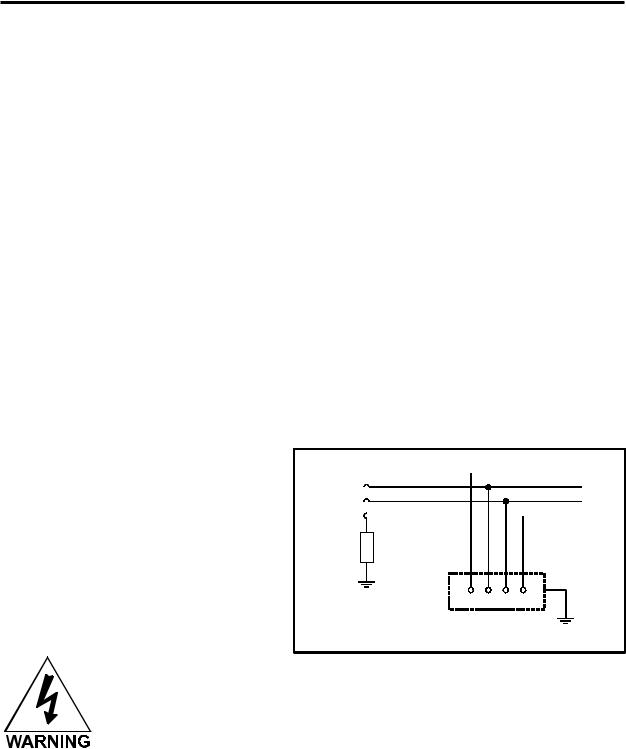
An IT type of electrical supply is acceptable if a standard power source is unavailable. An IT power system is a power distribution system having no direct connection to earth, the exposed conductive parts of the electrical installation being earthed.
L1

L2
L3 N
N 

Impedance
Power system |
PE |
|
|
||
earth |
Exposed conductive parts |
|
|
|
|
|
Example of IT power system |
|
Never remove the ground
lead to the electrical cord and plug the system into a non-grounded outlet. This is very dangerous and can lead to a severe, if not fatal, electrical shock. Always plug the system into a 3 prong grounded outlet.

Installation 2-3
If electrical power fluctuations, brown outs, or constant power outages are a problem in your area, an electrical line stabilizer, UPS (Uninterruptible Power Supply), or backup generator might be required. If installing any of these devices, make sure that they meet the electrical requirements of the laser system.
If there is any type of electrical problem present, please contact a locally licensed electrical contractor to correct the problem. If an incorrect electrical supply, voltage spike or surges damage the laser system, the damages WILL NOT be covered under warranty. It is your responsibility to provide a suitable electrical supply.
Exhaust Requirements
To properly exhaust fumes and smoke from the laser engraving system during operation, it is necessary for you to provide a proper exhaust system. This system MUST be capable of supplying 250 CFM (cubic feet per minute) @ 6 inches of static pressure (water).
Never operate the laser engraving system without a properly installed and operating
exhaust system. Some materials when cut or engraved can produce fumes that are
The blower MUST be mounted on the OUTSIDE of the building either on the roof or on a cement pad next to the building possibly mounted on vibration dampers.
Rigid tubing should be used for 90% of the distance traveled. The tubing should be smooth walled and have as few 90 degree bends as possible. Two 45 degree bends have better airflow than one 90-degree bend. Use tubing with a diameter that matches the blower unit (usually 6 inches/1524 mm) and use a 6 inch (1524 mm) to 4 inch (1016 mm) reducer to couple the tubing down to 4 inches (1016 mm) to within a few feet from the laser system. Do not connect the rigid tubing directly to the laser system. Use a short piece of industrial grade, wire reinforced rubber tubing to connect the end of the gate, or rigid tubing, to the laser system. This will provide mobility and will dampen blower vibrations. Use only a few feet because it’s spiral construction reduces airflow. Install a hose clamp on both ends of the hose to prevent leaks and to prevent the hose from slipping off. Finally, have the blower wired to a wall switch in the same room for easy ON/OFF control.
Also consider installing a gate to control airflow and to close off the exhaust from the outside environment when the laser is not in use. This is especially useful in colder climates where it can be damaging to the laser system to have cold air coming into it from the outside.
In order to meet the laser system’s CFM requirements, a high-pressure, high static pressure rated, exhaust blower must be installed. This type of blower has self-cleaning blades and can maintain airflow even though restrictions are introduced. Length of exhaust pipe, exhaust pipe diameter, number of 90degree angles, and other restrictions must be calculated when determining the correct exhaust blower unit. Installing an incorrect or undersized blower is not only unsafe, but it can also lead to premature and excessive wear and tear to the laser system.

2-4 Installation
DO NOT install forward incline, backward incline, in-line, or ventilator fans because these types of air handlers are inadequate and inappropriate for this type of installation. If your contractor has any questions concerning blower specifications or exhaust system requirements, please contact our Service Department directly before installation.
The following diagram shows a typical exhaust system layout. Use this as a guideline to proper exhaust system installation. Although these diagrams just serve as an example, we recommend installation of the exhaust system by a licensed contractor to meet safety and local code requirements as well as being able to calculate the correct size blower required for your particular installation.
The following diagram shows a typical exhaust system layout. Use these as a guideline to proper exhaust system installation. Although this diagram serves as an example, we recommend installation of the exhaust system by a licensed contractor to meet safety and local code requirements. Please contact a local air quality control specialist.
ROOF MOUNT INSTALLATION EXAMPLE
SIDE VIEW
SHIELD BLOWER 


 EXHAUST
FROM THE WEATHER
WITH PROTECTIVE ENCLOSURE

 EXHAUST BLOWER
ROOF |
WIRE BLOWER TO |
A WALL SWITCH |
SHUT OFF |
GATE(S) |
USE SMOOTH WALL TUBING SUCH AS SHEET METAL OR PVC THAT IS THE SAME DIAMETER AS THE BLOWER INLET. SEAL ALL JOINTS TO PREVENT FUME LEAKS. KEEP TUBING AS STRAIGHT AS POSSIBLE. BENDS REDUCE AIR FLOW.
REDUCE TO 4 INCHES WITH
A REDUCING COUPLER
Y-PIPE
4 INCH DIAMETER FLEXIBLE RUBBER HOSE

Installation 2-5
FRONT VIEW
|
FROM EXHAUST BLOWER |
Y-PIPE |
|
|
REDUCE TO 4 INCHES WITH |
|
A REDUCING COUPLER |
SHUT OFF |
SHUT OFF |
GATE |
GATE |
 4 INCH DIAMETER
FLEXIBLE RUBBER HOSE
Passing Through a Narrow
Doorway
If the doorway is not wide enough to allow to you roll the laser system through it, the system MUST be detached from the Cart Stand, rotated sideways, passed through the doorway, then re-attached to the Cart Stand. If your doorway is wide enough, you can skip the following procedure and proceed to “Leveling the System”.
The Laser System can weight up to 250 lbs. Obtain assistance from as many people as possible (3 or 4 people). Always use a back-support device. Do not attempt lifting the machine if you are physically handicapped or are injured in any way. Seek the advice of a physician if you are unsure.
It would help if you had a PADDED floor dolly to transport the machine through the doorway. If one is not available, it will need to be carried through the doorway.
1.Open the Rear Cover by pressing down on the button part of the latches until the latches pop up.
2.Fold the Rear Cover down to a resting position.

2-6 Installation
3.Locate and disconnect the two white Power Supply Cable Connectors. Gently push the cables all the way down into the cavity of the Power Supply enclosure. Close and latch the Rear Cover by pushing down on the latch until it clicks.
4.Remove any packing materials or accessories from inside the Laser System.
5.Using strong shipping tape or rope, tape the front door closed so that it does not open up when you tilt it.
6.Remove the eight(8) screws, flat washers, and lock washers that attach the Cart Stand to the Laser System from the bottom.
7.Lift the Laser System straight up, clearing the Cart Stand and the Power Supply Cables. Gently tuck the Power Supply
Connectors into their cavity so they do not interfere with re-assembly.
8.Place the Laser System face down on the dolly and roll it through the doorway. If you do not have a dolly, you will need to carry it through.
9.After you get the Laser System and the Cart Stand through the door, line carefully line up the Laser System and place it back on top of the Cart Stand.
Be careful not to pinch your fingers.
10.Attach your screws, flat washers, and lock washers. Re-connect the Power
Supply Connectors, close the Rear Cover and push down on the latches until they click and lock the cover into place.
11.Locate the laser system to its final resting position next to the computer and exhaust system.
Strong Tape
Power Supply

Connectors

Installation 2-7
Leveling the System
1.If the floor underneath the Laser System is uneven, the casters must be adjusted. Place a bubble level across the top of the legs directly above the front casters. Note the bubble position in its sight glass. Do the same for the back part of the legs and also note the position of the bubble in the sight glass. If the bubbles are in the same visual position, adjustment is not necessary and cart assembly is complete. If they are in different positions, adjustment is required.
2.To adjust the casters, choose ONLY ONE (1) caster and adjust its height until both bubbles are visually identical between the front casters and the back casters. The purpose of this step is to make sure that all casters lie in the same plane, not to level the laser system with the ground. If desired, you can level the laser system with the ground although it is not required.
|
|
|
|
|
|
|
L |
|
|
|
|
|
|
E |
|
|
|
|
|
|
V |
|
|
|
|
|
|
E |
|
|
|
|
|
|
|
EL |
|
|
|
|
|
|
L |
|
|
|
|
|
|
B |
|
|
|
|
|
|
B |
|
|
|
|
|
|
U |
|
|
|
|
|
|
|
B |
|
|
|
|
|
|
|
3.Open the top door and remove the rubber band that is holding the arm in place.
4.If you haven’t already done so, remove any remaining packing materials, accessories or any other items that may be located inside the cabinet or on top of the engraving table.
5.Gain access to the rear of the laser system to install the Laser Cartridge.
Laser Cartridge Installation
Before connecting and powering on your system, you must install the Laser Cartridge(s). Make sure that your power cord IS NOT plugged in at this time.
The following procedure is for both the X-600 and the X2-600 Platforms. The difference is that the X2600 can accommodate one or two Laser Cartridges. No matter which system you have, if you only have one Laser Cartridge, install it in the TOP position.

2-8 Installation
Open the Rear Cover and visually locate the Laser Mounting Block(s), the Laser Latch(es), and Alignment Fork(s). Notice that the Alignment Fork(s) have two plates, one small and one large. Locate the gap between the two plates.
Observe the “V” groove along the upper and lower part of the Laser Cartridge. Also locate the Alignment Plate at the end of the Laser Cartridge.
Pick up the Laser Cartridge by the sides. Tilt the Laser Cartridge downward on a 30-degree angle. If you have the X2-600 and you have two(2) Laser Cartridges, mount the cartridge onto the LOWER Mounting Blocks first. It does not matter if the power rating is different between the two lasers. Place the upper “V” groove of the cartridge on top of the Mounting Blocks. Slide the cartridge to the right until the Alignment Plate of the Laser Cartridge makes contact with the inside of the large plate of the Alignment Fork and is centered in the gap in the Alignment Fork between the small and large plates of the Alignment Fork.
Slowly rotate the Laser Cartridge making sure that the Alignment Plate is centered in the gap of the Alignment Fork. Keep rotating the laser until the Laser Latch “clicks” and locks the cartridge into place.
Make sure that you do not pinch any wires or hoses during this process. This may require some slight force to actuate the latch. Verify that the cartridge is resting, UNTILTED, and the Alignment Plate is centered within the Alignment Fork. If you have a second Laser Cartridge, mount it on the top mounts the same as the bottom Laser Cartridge. Remember if you only have one laser, mount it on the TOP Laser Mounts.

Installation 2-9
Plug in the Power Connector(s). Note that the Power Connector that is physically located higher is the one that you connect to the TOP Laser Cartridge because it has an extra wire that powers the Red Diode Laser Pointer located in the Laser Cartridge. The power connector(s) are keyed so it will only insert one way. If you only have one laser, leave the BOTTOM power connector unplugged.
Close the Rear Cover and push down on the latches until they “click”. Later on in this manual under the “Making the Connections” section, we will verify that you have installed the cartridge(s) correctly. For now, let’s assume that it is OK and move on to the next section.
Laser Cooling Requirements
This type of laser system uses fans to keep the laser cartridge and electronics cooled during operation. Maintain the room temperature at the recommended ambient temperature range outlined previously in the Operating Environment section.
Do not confine the back of the machine by surrounding it with furniture, shelving, backing it into a corner, etc. The backside of the laser system must be allowed to “Breathe” otherwise it can overheat the laser cartridge, power supply, and/or the CPU module. Overheating may cause serious and very costly damage to the laser system.
Computer Requirements
The following is the MINIMUM required computer configuration. Using a faster computer with more capacity will increase efficiency and throughput. Although using a computer that does not meet our minimum recommendation might be acceptable to you, a faster computer will definitely pay for itself in a short amount of time.
•Pentium 300 MHz or equivalent
•32 MB of RAM
•2 Gigabyte hard drive or bigger
•17 inch color VGA monitor
•3.5” floppy disk drive
•CD-ROM Drive
•Mouse or other pointing device
•Microsoft Windows 95
•600 DPI Optical Resolution Scanner
Remember that the laser system is an output device just like a printer is. The faster you can create graphics and manipulate your software, the faster you can download to the laser system to keep it producing.

2-10 Installation
Software Suggestions
The following is a list of recommended software programs. We do not endorse any particular software program neither do we guarantee its full compatibility with the laser system. Please refer to the Appendices section on known bugs/anomalies related to these particular software programs, related versions, and ones that are not listed below.
Graphics Programs
•CorelDraw
•Macromedia Freehand
Bitmap / Scanning Software
•Adobe Photoshop
•Adobe Streamline - for raster to vector conversion
CAD Software
•AutoCAD for Windows
•AutoCAD LT for Windows
•Autosketch for Windows
•DesignCAD for Windows
CAD users do not necessarily need Windows or Windows compatible programs. The laser system is compatible with any program that can output standard HPGL commands whether it is Windows based or not. Refer to the section on using DOS based CAD programs.
When a software company updates their version of their programs, it can sometimes cause conflicts with our printer driver. Our programmers constantly test new software programs and updated versions for compatibility. We will update our printer driver to address issues that we have control of. For bugs or problems with your software not related to the laser system, please contact the software manufacturer.
Font Requirements
True Type
We recommend using True Type fonts ONLY. TrueType fonts are the most versatile and should be used whenever possible. They provide the best print quality and will print well at any size.
PostScript
We do not recommend using PostScript fonts. The laser system is NOT a PostScript printer and therefore has no capability of printing PostScript fonts. Sometimes a PostScript font will print if you are running Adobe Type Manager (ATM). Adobe Type Manager converts PostScript fonts to bitmapped fonts before sending the information to our printer driver. Using ATM does not guarantee that the PostScript font will print properly therefore it is NOT recommended.
Bitmap
Bitmapped fonts only print well when used at the specific point size they were designed for. This point size is usually indicated in the font name such as Times Roman 12. If a font is only available in bitmap form, you must print it at the size it was created for. Scaling the font larger will result in a more jagged looking character although scaling it smaller produces good results.

Installation 2-11
Helpful Tip
If you are having any problems printing a font and you cannot figure out what is going on, select the font and “convert to curves” or “convert to paths” in your graphics software. This will convert the font into a bitmapped image and will print correctly to the laser system. Refer to your graphics software on how to convert fonts.
As you can see, we strongly recommend the use of True Type fonts only. Usually, most graphics programs, such as CorelDraw come with hundreds of fonts that you can install. For the average user there is more than enough to choose from.
Making the Connections
Please use the parallel cable supplied with the system. It is a 6-foot, high quality, shielded, IEEE1284 compliant cable. If you use a printer cable other than the one provided, it will violate the laser systems FCC and CE rating and may also cause harmful interference when downloading files to the laser system.
Please make the following connections in the exact order described otherwise static electricity can damage the computer and/or the laser system’s electronics.
•Connect the systems Power Cord and your computer Power Cord to the electrical outlet(s). Do not turn on either unit at this time.
• Connect the system to the computer using the parallel port connection.
•Connect the rubber flexible hose of your exhaust system to the exhaust port of the laser system.
•Turn on your computer ON and check your
computers BIOS setting for your parallel port. Make sure that it is set to either “ECP“ or
“Standard Parallel Port”. DO NOT SET IT TO “EPP” or “Bi-directional”. The laser system does not support these modes. If your computer is set to an incorrect configuration, erroneous data will be sent to the laser system during printing. This can cause the system to lock up, print garbage information, or not print at all. For information on how to check or adjust your computers BIOS setting, please refer to your computer’s owner manual or call their technical support department.
•Turn ON the laser system. After the system finishes initializing, “Ready” will appear displayed on the Control Panel of the laser system.
•We will now check if the Laser Cartridge(s) were installed
properly. To do this, open the top door and place a small piece of masking tape across the ¾” hole in the focus carriage. Gently rub the tape around the edge of the hole so that you can see the outline of the hole through the tape.
• Now press the “X-Y” button on the Control Panel. The red diode pointer will illuminate and a red dot will appear on the masking
tape. The dot should appear centered, or close to the center of
the hole, within 1/8”. If not, remove and re-install the laser cartridge and try again. If the red dot still does not appear within
1/8” of the center of the hole, please contact our Service  Department. Outline of Hole
Red Dot Masking Tape

2-12 Installation
•If the red dot is centered, installation is complete. Remove the masking tape.
•If you have second Laser Cartridge (the bottom one) installed, you must check it’s alignment also. To do this, you must first turn OFF the laser system.
•Disconnect the wire harness from the top Laser Cartridge and connect it into the bottom Laser Cartridge. Remember that only the TOP laser power connector has a wire that powers the Red Diode Pointer. The BOTTOM laser power connector does not even though BOTH Laser Cartridges are equipped with Red Diode pointers. We do this because we do not want two Red Diode pointers activated, only one.
•Turn the system ON and check the red dot like you did for the Top Laser Cartridge.
•If the bottom Laser Cartridge’s red dot is not centered within 1/8” of the center of the hole, please contact our Service Department.
Problem Prevention
The following are things that you MUST NEVER do:
1) Never connect or disconnect the printer cable while either the computer or the
laser system is powered ON. Always power down both units and leave them plugged into the wall outlet when connecting or disconnecting the printer cable.
2) Never connect the laser system through a manual switch type A/B switch box.
If connecting an additional laser system or other printer to the same computer, we recommend the installation of an additional parallel port into the computer. Using a switchbox can create electrical noise that can cause an engraving problem or can damage the laser system and/or the computer’s electronics.
3) Never use any device that is installed between the computers parallel port and the parallel port of the laser system such as a ZIP drive or parallel port CD-ROM
drive. This can not only damage the laser systems electronics but it usually will not work and will cause file transmission errors. Again, install an additional parallel port for other peripheral devices.
Computer Controlling the Laser System
At this time, you will need to read the second manual supplied with your system. It is called “Computerized Controls”. This manual contains Windows 95/98 printer driver installation and operation instructions as well as setup instructions for graphics software to properly work with the laser system. Please read this other manual before continuing on to Section 3.
SECTION 3
System Operation
In this section you will learn how the laser system actually works and will familiarize you with laser system terminology. We will then start working with the control panel and learn how to get around in the menu system. Since there are many features in this laser system, the menu system may seem complicated at first, but once you start using it, you will find out that it is a very simple system to operate.
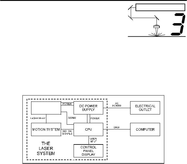
How it Works
There are five (5) basic components that make up a laser system, the control panel, the CPU, the DC power supply, the laser cartridge, and the motion system.
LASER
CARTRIDGE
DC Power Supply
The DC power supply converts the incoming AC electricity to 48 volts DC. This is used to power both the laser cartridge and the CPU.
CPU
The CPU is the “brains” of the system and controls everything. Located on the CPU are standard computer memory SIMMS. This is where incoming files, from the computer, are stored while the power is on. The CPU gets input from the computer and the control panel. It outputs precisely timed signals to fire the laser beam and to move the motion system simultaneously.
Control Panel
This is where the operator controls the laser system. It is composed of tactile feel push buttons and a LCD display. From this panel, the operator can position the motion system, move around through the menu system in the LCD display, and run the laser system.

3-2 System Operation
NOTE: Before describing the complex functionality of the SUPERSPEED, in the following diagram, we demonstrate how a typical single-laser system works. We will then show how the SUPERSPEED builds upon this foundation and utilizes two Laser Cartridges to operate in a Dual Laser Single Beam Mode or Dual Laser Dual Beam Mode.
Laser Cartridge
The laser cartridge is a very sophisticated device. It is composed of a plasma tube filled with a special mixture of CO2 and other gases, and RF (radio frequency) electronics. The function of the entire assembly is to turn electrical energy into concentrated light energy. The word LASER is an acronym for Light Amplification by Stimulated Emission of Radiation.
|
|
|
|
|
|
|
|
|
|
LASER CARTRIDGE |
||||||||||
|
|
|
|
|
|
|
|
|
|
|
|
|
|
|
|
|
|
|
|
|
#1 MIRROR |
|
|
|
|
|
GAS FILLED PLASMA TUBE |
||||||||||||||
|
|
|
|
|
|
|
|
|
|
|
|
|
|
|
||||||
|
|
|
|
|
|
|
ELECTRODES |
|||||||||||||
|
|
|
|
|
|
|
|
|
|
|
|
|
||||||||
|
|
|
|
|
|
|
|
|
|
|
|
|
|
|
|
|
|
|
|
|
|
|
|
|
|
|
|
|
|
|
|
|
RF ELECTRONICS |
|
|
||||||
|
|
|
|
|
BEAM WINDOW |
|||||||||||||||
|
|
|
|
|
BEAM DIAMETER |
|||||||||||||||
|
|
|
|
|||||||||||||||||
|
|
|
|
|
|
|
|
|
|
|
|
|
|
#3 MIRROR |
||||||
#2 MIRROR |
|
|
|
|
|
|
|
|
|
|
|
|
|
|||||||
|
|
|
|
|
|
|
|
|
|
|
|
|
|
|
|
|
FOCUS LENS |
|||
|
|
|
|
|
|
|
|
|
|
|
|
|
|
|
|
|
||||
|
|
|
|
|
|
|
|
|
|
|
|
|
|
|
||||||
|
|
|
|
|
|
|
|
|
|
|
|
|
|
|
|
|
||||
|
|
|
|
|
|
|
|
|
|
|
||||||||||
|
|
|
|
|
|
|
|
FOCAL LENGTH |
||||||||||||
|
|
|
|
|
|
|
|
|
|
|
|
|
|
|
|
FOCAL RANGE |
||||
|
|
|
|
|
|
|
|
|
|
|
|
|
|
|
|
|
|
|
|
|
|
|
|
|
|
|
|
|
|
|
|
|
|
|
|
|
|
|
|
|
|
|
|
|
|
MATERIAL |
|
|
|
|
|
|
|
|
|
|
|
|
|
|||
|
|
|
|
|
|
|
SPOT |
|
|
|
|
|
||||||||
|
|
|
|
|
|
|
|
|
|
|
|
|
||||||||
|
|
|
|
|
|
|
|
|
|
|
|
|
|
|
|
|
|
|
|
|
The laser cartridge receives power from the 48VDC power supply and its “trigger signal” from the CPU. When the laser system is power on and the trigger signal comes from the CPU, the RF electronics produce a 40 MHz signal across the electrodes located inside the plasma tube. This causes spontaneous photon emissions from the gas mixture that produces an invisible, infrared light beam at a frequency of 10.6 microns.
The laser beam exits the laser cartridge through its output optics, reflects off the #1 mirror, passes through the beam window, reflects off the #2 and #3 mirrors and then finally passes through the focus lens. The #2 and #3 mirror and the focusing lens are all mounted to the motion system. The width of the laser beam as it exits the tube, called the “Beam Diameter”, is about 4 mm. The focus lens focuses the beam into a very small spot where the “Spot Size” is dependent on the “Focal Length” of the lens. The “Focal Length” is the distance from about the center of the lens to the point where the beam converges into the smallest spot possible. Using a standard 2 inch focal length lens, the spot size produced is approximately .005 inches.

System Operation 3-3
The “Focal Range” of the lens, where the beam is considered to be “in focus”, is equivalent to +/- 5% above and below the focus point. Shorter lenses produce a smaller spot size but also have a very narrow focal range. This means that it would only be useful for engraving very flat objects. The longer lenses have a much wider range of focus but also produce a larger spot size that would prohibit the engraving of fine detail. This can be related to trying to write small text with a wide, felt tip marker. There are pros and cons to the different lenses that are available for different applications. Please refer to the Appendices section on available lenses and their operating characteristics.
“Wattage” signifies the amount of heat energy that the laser light is producing over a period of time. Laser energy is measured with a laser power meter that measures the unfocused laser beam’s heat output over a calibrated period of time.
Motion System
The motion system consists of the mechanically moving parts of the laser system. It is made up of rails, motors, bearings, belts, mirrors, a lens, and other parts. There are two directions of motion, left and right is called the “X” direction and front to back is called the “Y” direction.
The CPU controls the movement of the motors, which moves the mirrors and focus lens across the engraving area and over the material. At the same time, it is synchronizing the laser pulses with the position of the focus lens. It is this precise positioning and timing of the laser pulses that produces the highest quality and fastest speed of engraving.
In summary, the five (5) components work together to take the graphic image that is downloaded to the laser system from your computer and burn it into the material located on the engraving table inside of the laser system.
The Control Panel
The control panel on the laser system provides easy access to all of the controls necessary for cutting and engraving operations. The control panel consists of a liquid crystal display (LCD), indicator lights, and selection buttons. The following section will describe, in detail, how to maneuver through the menu system and the significance of each item in the control panel.

3-4 System Operation
The Liquid Crystal Display (LCD)
The LCD is a four line display that displays the menus that control the laser system. It is a backlit type of display that enhances visibility even under low light environments.
When the laser system is powered on, the laser system will perform a series of routines. “INITIALIZING” will display until the motion system and electronics have finished their routines. When completed, the display will then read “READY”, signifying that the laser system is ready to accept files.
DO NOT download files until the display reads “READY” as this can lead to an incorrect or corrupted file download. Corrupted file downloads can lead to an incorrect firing of the laser which can destroy the material you are engraving.
The two up and down arrow buttons to the right side the LCD give complete access to the menu control system. Use these arrow buttons to move the cursor up or down through the items in the display.
Both of these buttons each serves two purposes. Depending on which menu you are in at the time, the “SELECT” button either enters you into that menu item the cursor is currently on, or it toggles that menu item to display different choices. Some items in the display lead to other menus and some are settings that can be adjusted. The “ESCAPE” button, depending on which menu you are in at the time, either exits you back to the previous menu or it nullifies or cancels any changes that you have made to that menu item. Continuously pressing the “ESCAPE” button will eventually bring you back to the “MAIN” menu.
The indicator lights will act differently depending on the current state of the laser system. The chart below describes the conditions of the indicator lights during different modes of operation.

|
|
System Operation |
3-5 |
|
|
Green Indicator Light |
|
|
|
|
|
|
CONDITION |
REASON |
|
|
ON |
The laser system is powered up, the top door is closed and the system is |
|
|
|||
|
|
ready to receive a file |
|
|
|
The laser system has finished processing a file and has returned to the home |
|
|
|
position |
|
|
|
The laser system has been paused while running a file |
|
|
OFF |
The top or front door is open |
|
|
|
The laser system is firing the beam in the Alignment Mode |
|
|
FLASHING |
The file is running |
|
|
|
Red Indicator Light |
|
|
|
|
|
|
CONDITION |
REASON |
|
|
ON |
The laser system is initializing |
|
|
|
||
|
|
The laser system is firing the beam in the Alignment Mode |
|
|
OFF |
The laser system has finished initializing and is ready to receive a file |
|
|
|
The top or front door is closed |
|
|
FLASHING |
The top or front door is open |
|
The Process Controls
These control the actual running of the laser system.
Runs the current file displayed in the “File Display” menu.
If a file is running, the “PAUSE” button halts the engraving or cutting process. When paused, the motion system arm will move to its home position in the upper right corner of the engraving area. When ready to continue operation, press the “RESUME” button and the system will begin cutting or engraving again exactly where it left off. If you wish to run the file from the beginning after pressing the “PAUSE” button, press the “START” button. When “Curve Enhancement” mode is selected in the driver, the
“Resume” button acts like the “Start” button and will start your file from the beginning.
During slow raster or vector motions, the motion system might not pause immediately after the “PAUSE” button is pressed. It can take a few seconds or several seconds to stop the system because it needs to complete the motion commands that it is currently running. Opening the top door also works similar to the “PAUSE” button but not exactly. The first thing the laser system will do is turn off the laser beam immediately after the door is opened. The next thing it will do is pause the motion system. Since opening the door and the pausing of the motion system are not precisely synchronized if you do this, resuming the file might cause an area of missed engraving. Opening the door to turn off the laser and to pause the motion system should only be used for safety or emergency reasons.
 Loading...