

Page 1
1-800-547-5740 • Fax: (503) 643-6322
www.ueitest.com • email: info@ueitest.com
MA1
INSTRUCTION MANUAL
Page 2
Introduction
The MA1 is a high sensitivity direct reading AC ammeter. It is designed
to simplify the setting of oil and gas thermostat heat anticipator and for
measuring the performance of AC relays, solenoids and other low current AC devices.
Features include
• Ranges: 0 - 1.2 AC Amps
• A c c u r a cy: ±3% of full sca l e
Safety Notes
Before using this meter, read all safety information carefully. In
this manual the word "WARNING" is used to indicate conditions
or actions that may pose physical hazards to the user. The word
"CAUTION" is used to indicate conditions or actions that may
damage this instrument.
Operating Instructions
WARNING!
Like all direct reading ammeters, the MA1 must be connected IN
SERIES with the circuit under test. The maximum value of current
that can be measured with the MA1 is 1.2 AC amperes (1,200 AC
milliamps). Do not exceed this value or the MA1 may be damaged.
Testing Heat anticipator
For the most efficient operation, the heat anticipator in the thermostat
must be set to correspond to the value of the control circuit current.
Thermostats are of two types: preset or adjustable. Many cooling
thermostats and some heating thermostats are preset. these require
no adjustment.
Adjustable thermostats should be set to the value of current noted on
the furnace rating label. If this information is not available then the
control current must be measured and the heat anticipator set to the
measured value of current as follows:
1. Remove the thermostat cover from the sub base.
2. Set the furnace controls to the ON position
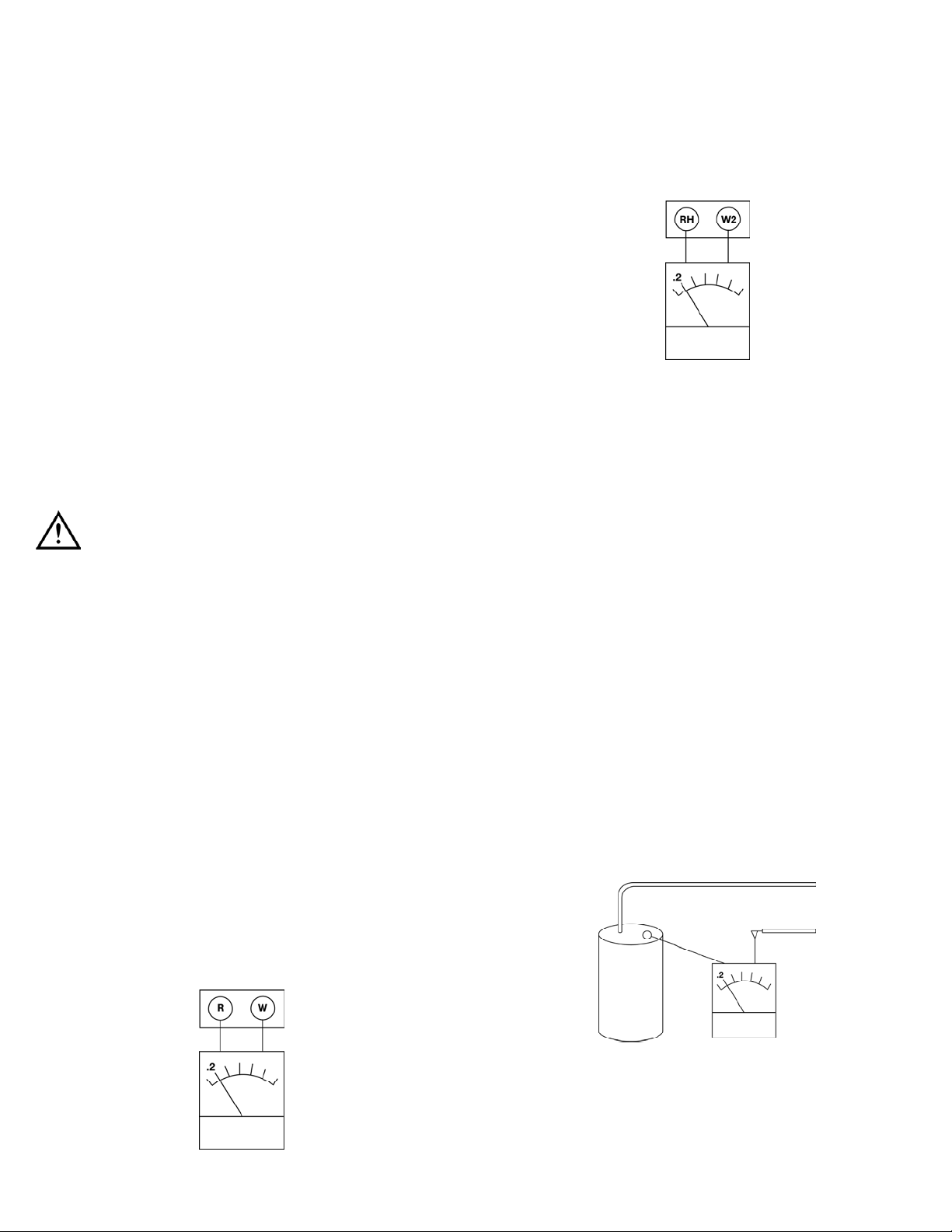
3. For thermostats with a single stage heat control connect one lead
of the MA1 to the “R” terminal on the sub base and the other
lead of the MA1 to the “W” terminal (Fig 1).
4. Note the magnitude of the current on the meter scale of the MA.
Set the heat anticipator to this value of current.
5. For thermostats with a two stage heat control repeat steps 1 thru
4 for stage 1. The second stage heat control current is measured
by connecting one lead of the MA1 to the “RH” terminal and the
other lead to the “W2” terminal (Fig 2).
6. Replace the thermostat cover and check the system for
proper operation.
NOTE: If a fan limit control is used this can affect the length of
the heating cycle. Check the ON and OFF fan control set points.
NOTE: If a longer heating cycle is desired, the pointer on the sub base
can be adjusted to a slightly higher setting. If a shorter cycle is desired
the pointer can be adjusted to a slightly lower setting.
Typical Values of Control Circuit Current:
1. 0.2 amperes for gas furnace without spark igniter.
2. 0.4 thru 0.8 amperes for gas furnace with spark igniter.
3. 1.0 amperes for oil furnace.
Other Uses For MA1
The MA1 can also be used to check the operating current of AC relays,
solenoids, motors and other devices rated at 1.2 AC amperes or less.
1. Turn OFF the power to the device to be tested.
2. Disconnect one of the power input leads at the device to be tested.
3. Connect one lead of the MA1 to the device and the other lead to
the power input wire previously disconnected (Fig 3).
MA1-MAN P. 1
(Fig 1)
(Fig 2)
(Fig 3)
MA1
Typical
sub base
MA1
Power input lead
MA1
Typical
sub base
Motor
Page 3

4. Check to make sure that the lead connections are not shorting to
each other or the frame.
5. Turn ON the power and read the current on the MA1.
6. Readings higher than normal can indicate: shorted turns in the
winding, high supply voltage, or restricted rotation in motors.
7. Readings lower than normal can indicate low supply voltage or
dirty or corroded electrical connections.
8. Turn OFF the power and disconnect the MA1. Reconnect, repair or
replace the device, as required.
M a i n t e n a n c e
Periodic Service
WARNING!
Repair and service of this instrument is to be performed by qualified
personnel only. Improper repair or service could result in physical
degradation of the meter. This could alter the protection from
electrical shock and personal injury this meter provides to the
operator. Perform only those maintenance tasks that you are
qualified to do.
These guidelines will help you attain long and reliable service from
your meter:
• Calibrate your meter annually to ensure it meets original
performance specifications
• Keep your meter dry. If it gets wet, wipe dry immediately.
Liquids can degrade electronic circuits
• Whenever practical, keep the meter away from dust and
dirt that can cause premature wear
• Although your meter is built to withstand the rigors of daily
use, it can be damaged by severe impacts. Use reasonable
caution when using and storing the meter
Cleaning
Periodically clean your meter’s case using a damp cloth. DO NOT use
abrasive, flammable liquids, cleaning solvents, or strong detergents as
they may damage the finish, impair safety, or affect the reliability of the
structural components.
MA1-MAN P. 2
Page 4

Limited Warranty
The MA1 is warranted to be free from defects in materials and workmanship for a period of
one years from the date of purchase. If within the warra n ty period your instrument should
become inoperative from such defects, the unit will be repaired or replaced at UEi’s option.
This warra n ty covers normal use and does not cover damage which occurs in shipment or
failure which results from alteration, tampering, accident, misuse, abuse, neglect or improper
maintenance. Batteries and consequential damage resulting from failed batteries are not
covered by warra n ty.
Any implied warranties, including but not limited to implied warranties of merchantability
and fitness for a particular purpose, are limited to the express warranty. UEi shall not be
liable for loss of use of the instrument or other incidental or consequential damages,
expenses, or economic loss, or for any claim or claims for such damage, expenses or
economic loss. A purchase receipt or other proof of original purchase date will be required
before warra n ty repairs will be rendered. Instruments out of warra n ty will be repaired (when
r e p a i r able) for a service charge. Return the unit postage paid and insured to:
1-800-547-5740 • FAX: (503) 643-6322
www.ueitest.com • Email: info@ueitest.com
This warranty gives you specific legal rights. You may also have other rights which vary from
state to state.
MA1
AC Ammeter
Copyright © 2007 UEi MA1-MAN 1/07
PLEASE
RECYCLE
 Loading...