

Page 1
AUTO4-2
1-800-547-5740 • Fax: (503) 643-6322
www.ueitest.com • email: info@ueitest.com
Auto 2-2,AU T O 4-2 & AG A 5 0 0 0
®
INSTRUCTION MANUAL
Page 2

DESCRIPTION
The UEI range of emission analyzers covering the models Auto 2-2, 4-2 and
AGA5000 has been designed to be used on petrol, LPG or CNG powered
engines*. All models measure carbon monoxide (CO), and unburnt
hydrocarbons (HC), with Oxygen (O2) and carbon dioxide (CO2) added to
four-gas models and nitric oxide (NO) included in five-gas variants. All fourgas analyzers have an upgrade facility for Nitric Oxide (NO).
Using the measured parameters CO, HC, O2 and CO2, additional parameters
such as Lambda, Air to Fuel ratio and corrected carbon monoxide (COK) can
also be calculated and displayed.
All measured and calculated parameters can be printed on the optional
infrared printer or saved to the analyzer’s memory.
Each analyzer is supplied with an RS232 output enabling communication
between the analyzer and a PC. Using the optional auto software kit, live
emission data can be displayed, saved directly to the PC or printed to
produce high quality test reports. Data stored in the analyzer can also be
uploaded, diagnosed graphically and/or converted into spreadsheets for
service records.
All models are battery powered to give true portability in the workshop
environment. The battery can be charged with the supplied mains adaptor
or 12V cable.
* For diesel applications, HC measured in the exhaust gas is indicated in ppm
(parts per million) n-hexane.
Page 3

CONTENTS
1. ANALYZER LAYOUT AND FEATURES . . . . . . . . . . . . . . . . . . . . . . . . . . . . . . . . . . . . . . . . . . . . . . 1
1.1 Instrument features and keypad . . . . . . . . . . . . . . . . . . . . . . . . . . . . . . . . . . . . . . . . . . . . . . . . . . . 1
1.2 Instrument layout (Rear) . . . . . . . . . . . . . . . . . . . . . . . . . . . . . . . . . . . . . . . . . . . . . . . . . . . . . . . . 2
1.3 Standard Probe Configuration . . . . . . . . . . . . . . . . . . . . . . . . . . . . . . . . . . . . . . . . . . . . . . . . . . . . . 3
2. SAFETY WARNING . . . . . . . . . . . . . . . . . . . . . . . . . . . . . . . . . . . . . . . . . . . . . . . . . . . . . . . . . . . . . 4
3. FIRST TIME USE . . . . . . . . . . . . . . . . . . . . . . . . . . . . . . . . . . . . . . . . . . . . . . . . . . . . . . . . . . . . . . . 4
4. NORMAL START UP SEQUENCE . . . . . . . . . . . . . . . . . . . . . . . . . . . . . . . . . . . . . . . . . . . . . . . . . . 5
4.1 Every Time You Use The Analyzer . . . . . . . . . . . . . . . . . . . . . . . . . . . . . . . . . . . . . . . . . . . . . . . . . . 5
4.2 Automatic Zero Calibration . . . . . . . . . . . . . . . . . . . . . . . . . . . . . . . . . . . . . . . . . . . . . . . . . . . . . . . 5
4.3 Main Display Parameters . . . . . . . . . . . . . . . . . . . . . . . . . . . . . . . . . . . . . . . . . . . . . . . . . . . . . . . . 7
4.3.1 Line Scroll Mode . . . . . . . . . . . . . . . . . . . . . . . . . . . . . . . . . . . . . . . . . . . . . . . . . . . . . . . . . . 7
4.3.2 4 Page Mode . . . . . . . . . . . . . . . . . . . . . . . . . . . . . . . . . . . . . . . . . . . . . . . . . . . . . . . . . . . . . 8
4.3.3 8 Page Mode . . . . . . . . . . . . . . . . . . . . . . . . . . . . . . . . . . . . . . . . . . . . . . . . . . . . . . . . . . . . . 8
4.4 Sampling the Exhaust Gas . . . . . . . . . . . . . . . . . . . . . . . . . . . . . . . . . . . . . . . . . . . . . . . . . . . . . . . 9
4.5 Turning the Pump ON/OFF . . . . . . . . . . . . . . . . . . . . . . . . . . . . . . . . . . . . . . . . . . . . . . . . . . . . . . . 9
4.6 Taking an oil temperature reading (certain analyzers only) . . . . . . . . . . . . . . . . . . . . . . . . . . . . . .10
4.7 Reading the engine speed (RPM) (certain analyzers only) . . . . . . . . . . . . . . . . . . . . . . . . . . . . . . .10
4.8 Regular Checks During Sampling . . . . . . . . . . . . . . . . . . . . . . . . . . . . . . . . . . . . . . . . . . . . . . . . . 10
4.8.1 Low Flow . . . . . . . . . . . . . . . . . . . . . . . . . . . . . . . . . . . . . . . . . . . . . . . . . . . . . . . . . . . . . . . 11
4.9 Normal Shutdown Sequence . . . . . . . . . . . . . . . . . . . . . . . . . . . . . . . . . . . . . . . . . . . . . . . . . . . . . 11
5. MOVING THROUGH THE MENUS . . . . . . . . . . . . . . . . . . . . . . . . . . . . . . . . . . . . . . . . . . . . . . . . 12
5.1 Basic Operation . . . . . . . . . . . . . . . . . . . . . . . . . . . . . . . . . . . . . . . . . . . . . . . . . . . . . . . . . . . . . . 12
5.2 Menu Options and Settings . . . . . . . . . . . . . . . . . . . . . . . . . . . . . . . . . . . . . . . . . . . . . . . . . . . . . . 13
5.2.1 Main Menu . . . . . . . . . . . . . . . . . . . . . . . . . . . . . . . . . . . . . . . . . . . . . . . . . . . . . . . . . . . . . 13
5.2.2 Select Menu . . . . . . . . . . . . . . . . . . . . . . . . . . . . . . . . . . . . . . . . . . . . . . . . . . . . . . . . . . . . . 13
5.2.3 Units Menu . . . . . . . . . . . . . . . . . . . . . . . . . . . . . . . . . . . . . . . . . . . . . . . . . . . . . . . . . . . . . 14
5.2.4 Display Menu . . . . . . . . . . . . . . . . . . . . . . . . . . . . . . . . . . . . . . . . . . . . . . . . . . . . . . . . . . . 15
5.2.5 Set-Up Menu . . . . . . . . . . . . . . . . . . . . . . . . . . . . . . . . . . . . . . . . . . . . . . . . . . . . . . . . . . . . 16
6. PRINTING INFORMATION - OPTIONAL EXTRA ONLY . . . . . . . . . . . . . . . . . . . . . . . . . . . . . . .17
6.1 Printing a Live Test . . . . . . . . . . . . . . . . . . . . . . . . . . . . . . . . . . . . . . . . . . . . . . . . . . . . . . . . . . . . 17
6.2 Standard Printout . . . . . . . . . . . . . . . . . . . . . . . . . . . . . . . . . . . . . . . . . . . . . . . . . . . . . . . . . . . . . 17
Page 4

7. STORING AND RETRIEVING DATA . . . . . . . . . . . . . . . . . . . . . . . . . . . . . . . . . . . . . . . . . . . . . . . 18
7.1 Storing a Live Test . . . . . . . . . . . . . . . . . . . . . . . . . . . . . . . . . . . . . . . . . . . . . . . . . . . . . . . . . . . . 18
7.2 Viewing and Printing a Stored Test . . . . . . . . . . . . . . . . . . . . . . . . . . . . . . . . . . . . . . . . . . . . . . . . 18
7.3 Deleting Data . . . . . . . . . . . . . . . . . . . . . . . . . . . . . . . . . . . . . . . . . . . . . . . . . . . . . . . . . . . . . . . . 20
7.4 Auto Store . . . . . . . . . . . . . . . . . . . . . . . . . . . . . . . . . . . . . . . . . . . . . . . . . . . . . . . . . . . . . . . . . . 21
8. MAINTENANCE . . . . . . . . . . . . . . . . . . . . . . . . . . . . . . . . . . . . . . . . . . . . . . . . . . . . . . . . . . . . . . . 22
8.1 Emptying and Cleaning the in-line water trap . . . . . . . . . . . . . . . . . . . . . . . . . . . . . . . . . . . . . . . . .22
8.2 Changing the particle filter . . . . . . . . . . . . . . . . . . . . . . . . . . . . . . . . . . . . . . . . . . . . . . . . . . . . . . 22
9. PROBLEM SOLVING . . . . . . . . . . . . . . . . . . . . . . . . . . . . . . . . . . . . . . . . . . . . . . . . . . . . . . . . . . . 23
10. ZERO CHECKS AND RE-CALIBRATION . . . . . . . . . . . . . . . . . . . . . . . . . . . . . . . . . . . . . . . . . . . 24
10.1 Zero Setting . . . . . . . . . . . . . . . . . . . . . . . . . . . . . . . . . . . . . . . . . . . . . . . . . . . . . . . . . . . . . . . . 24
10.2 HC residue check (certain analyzers only) . . . . . . . . . . . . . . . . . . . . . . . . . . . . . . . . . . . . . . . . . . 25
10.3 Leak Check . . . . . . . . . . . . . . . . . . . . . . . . . . . . . . . . . . . . . . . . . . . . . . . . . . . . . . . . . . . . . . . . 26
10.4 Gas Calibration Verification . . . . . . . . . . . . . . . . . . . . . . . . . . . . . . . . . . . . . . . . . . . . . . . . . . . . . 27
10.4.1 Calibration Gas Values . . . . . . . . . . . . . . . . . . . . . . . . . . . . . . . . . . . . . . . . . . . . . . . . . . . . 27
10.4.2 Calibration Check . . . . . . . . . . . . . . . . . . . . . . . . . . . . . . . . . . . . . . . . . . . . . . . . . . . . . . . . 28
10.4.3 User Re-calibration . . . . . . . . . . . . . . . . . . . . . . . . . . . . . . . . . . . . . . . . . . . . . . . . . . . . . . 29
10.4.4 Printed Calibration Report . . . . . . . . . . . . . . . . . . . . . . . . . . . . . . . . . . . . . . . . . . . . . . . . . .30
10.4.5 Reset Instrument Calibration . . . . . . . . . . . . . . . . . . . . . . . . . . . . . . . . . . . . . . . . . . . . . . . 31
11. PRODUCT SPECIFICATION . . . . . . . . . . . . . . . . . . . . . . . . . . . . . . . . . . . . . . . . . . . . . . . . . . . . . 32
APPENDICES
A. Main Display Parameters . . . . . . . . . . . . . . . . . . . . . . . . . . . . . . . . . . . . . . . . . . . . . . . . . . . . . . . . . . 34
B. LAMBDA Calculation . . . . . . . . . . . . . . . . . . . . . . . . . . . . . . . . . . . . . . . . . . . . . . . . . . . . . . . . . . . . . . 35
C. Procedure for changing Oxygen fuel cell . . . . . . . . . . . . . . . . . . . . . . . . . . . . . . . . . . . . . . . . . . . . . . . 36
D. Electromagnetic Compatibility (CE) Statement . . . . . . . . . . . . . . . . . . . . . . . . . . . . . . . . . . . . . . . . . . . 36
Page 5
1
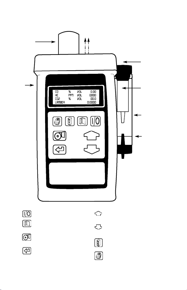
1. ANALYZER LAYOUT AND FEATURES
1.1 Instrument Features and Keypad
Infra-red signal to printer
Battery
Charger
or 12 Volt
Adapter
Gas Connection to
Instrument
External Particle
Filter
In-line Water Trap
(Keep clear of
water at all times)
Water
Level Limit
ON/OFF
MENU
Allows access to all menu functions
PUMP
Turns pump on and off
ENTER
Accepts a command,
i.e. enters a menu option
UP
Scrolls up through options, i.e. Fuel
DOWN
Scrolls down through options
STORE
Enters data storage menu
PRINT
Prints current data
Turns on backlight
NO sensor
(standard on
AGA5000 only)
Page 6
2
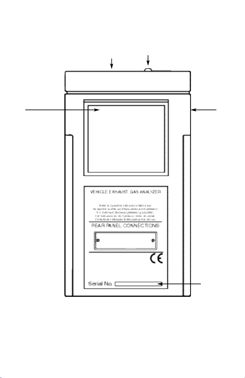
Instrument Layout (Rear)
1.2 Instrument Layout (Rear)
Serial
Number
NOTE! Cover
Does Not
Remove
Charger
Socket
Exhaust Port
*Note: DO NOT cover exhaust port as this will severely affect analyzer operation
IR Emitter
Page 7
3
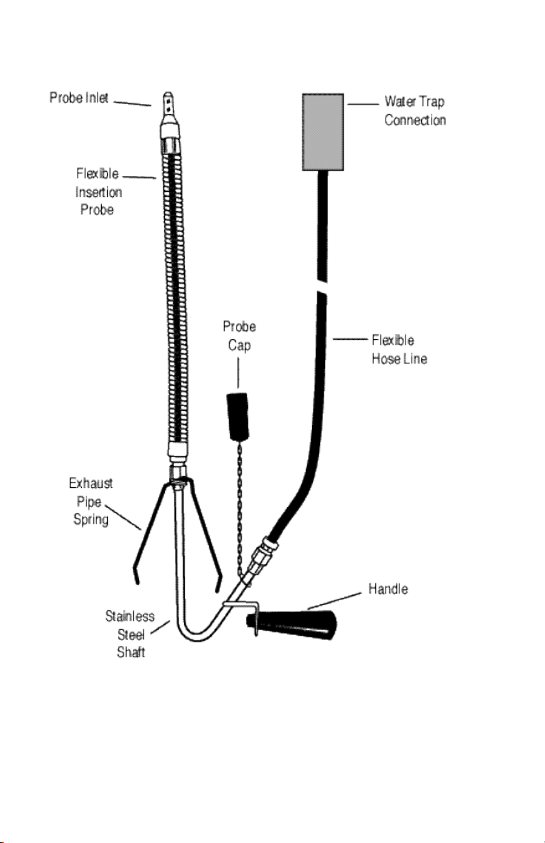
1.3 Standard Probe Configuration
Page 8

4
2. SAFETY WARNING
This analyzer extracts combustion gases that may be toxic in relatively low concentrations. These gases are
exhausted from the top of the instrument. This instrument must only be used in well ventilated locations. It
must only be used by trained and competent persons after due consideration of all the potential hazards.
Protection Against Electric Shock (in accordance with EN 61010-1: 1993)
This instrument is designated as Class III equipment and should only be connected to SELV circuits. The
battery charger is designated as:
Class II equipment
Installation category II
Pollution degree 2
Indoor use only
Altitude to 2000m
Ambient temperature 0˚C-45˚C
Maximum relative humidity 80% for temperatures up to 31˚C decreasing linearly to 50%RH at 45˚C
Mains supply fluctuations not to exceed 10% of the nominal voltage.
3. FIRST TIME USE
Charge the battery for 12 hours, following this an overnight charge should be sufficient for an average 8
hour day (turning pump off to save power between tests). See Main Parameter displays for Battery Indicator.
The analyzer has a rechargeable lead acid battery, use only the mains charger or 12 volt adapter supplied or
damage may occur to the instrument and battery.
Check that you have all the items you have ordered.
Take time to read this manual fully.
When using the analyzer for the first time you will need to choose from:-
Language selection
Time
Printed header name and telephone number
The Menu Options and Settings (Section 5.2.5) gives details of how to change the above settings.
Page 9
5
4. NORMAL START UP SEQUENCE
4.1 Every Time You Use The Analyzer
BEFORE SWITCH-ON CHECK THAT:
• The particle filter is dry and not dirty or damaged
• The water trap and probe line are empty of water
• All hose connections, etc. are properly made
• The probe is sampling CLEAN AMBIENT air
• The water trap is correctly fitted and the instrument upright
• The oil temperature probe is connected if required (Certain analyzers)
*DO NOT RUN ANALYZER WITHOUT WATER TRAP FITTED
Switch ON the instrument by pressing
4.2 Automatic Zero Calibration
During this sequence the analyzer pumps fresh air into the sensors to allow them to zero and the oxygen
sensor to be set to 20.9 %.
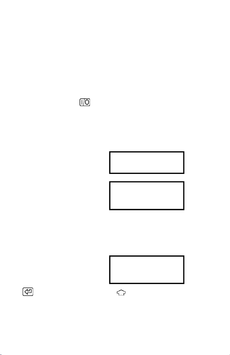
After switch-on the analyzer will briefly display header information:
And then show the initializing screen:
The time will count down in seconds to zero and is pre-set by the instrument. During countdown the
instrument will check flow rate and initialize the measuring system, do not block the end of the probe or
insert into or near the vehicle exhaust.
Once the initialization time has reached zero an audible beep will be heard and the option to perform a leak
test will be given. The following screen will be displayed:
Press to select YES and perform a leak test or use and enter NO to skip.
UEI
1-503-644-8723
INITIALIZING
TIME: 75
FRESH AIR PURGE
LEAK CHECK?
YES
PRESS ENTER
Page 10
6
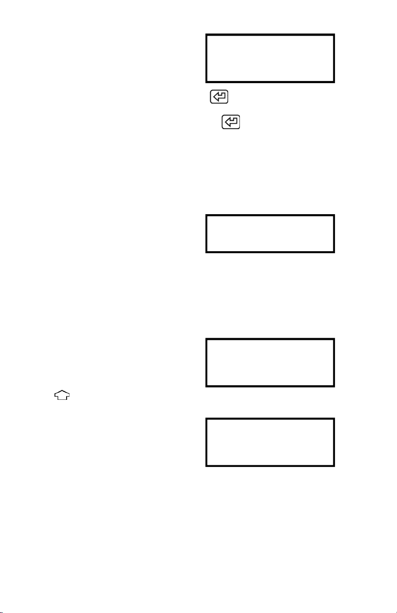
If YES is selected the following screen will be displayed :
Fit the probe seal as detailed in Section 10.3 and press
Once the test has PASSED remove the probe seal and press
If the test fails see Section 10.3.
Once the leak test is completed the instrument will zero the CO, HC and CO2 sensors and set oxygen to
20.9%. Keep the instrument and exhaust probe sampling fresh air.
The instrument will take approximately 75 seconds to set the zero.
If the readings are outside the allowable zero range as detailed in section 10 it is advisable to perform a
manual zero also detailed in section 5.2.2.
A HC residue check may also be requested. See Section 10.2.
The next screen is the MAIN DISPLAY of the analyzer:
Use to change the display.
All parameters are detailed in Appendix A - MAIN
DISPLAY PARAMETERS.
LEAK CHECK?
REMOVE EXHAUST PROBE
FIT PROBE SEAL
THEN PRESS ENTER
ZERO CAL
TIME: 75
FRESH AIR PURGE
CO % VOL 00.00
HC PPM VOL 0000
CO2 % VOL 00.0
O2 % VOL 20.90
CO % VOL 00.00
HC PPM VOL 0000
CO2 % VOL 00.0
LAMBDA 0.0000
Page 11
7
4.3 Main Displays
The main display can be changed to show either 4 or 8 parameters at one time. Two options are available
when 4 parameters are selected.
• Line scroll mode allows you to customize the display to show the data you require.
• 4 Page Mode displays 4 lines of data in set format, each page is predefined
• 8 Page Mode displays 8 parameters on 4 lines in set format, the bottom two can be changed.
Changing between the different modes is detailed in Display Menu (Section 5.2.4.)
TIP! To turn the backlight ON in the main display press
Note: a short press turns the backlight on, a press and hold will print.
To increase battery life do not leave the backlight on.
4.3.1 Line Scroll Mode
Line scroll mode allows you to customize the bottom line of the display. This is the default mode following
analyzer turn on.
Use the key to change the bottom line of the display.
Change bottom line using
4.3.2 Page Mode
Use the key to change the information that is displayed on the screen. The following pages are
available, depending on model the sequence of displayed parameters may differ from those in the examples
which follow.
CO % VOL 00.00
HC PPM VOL 0000
CO2 % VOL 00.0
LAMBDA 0.0000
GASOLINE
DATE . . . . . . . . . . . . .07-08-01
TIME . . . . . . . . . . . . . . . .12:31:35
BATTERY % . . . . . . . . . . . . .54
CO % VOL . . .00.00
HC PPM VOL . . . .0000
CO2 % VOL . . . .00.0
O2 % VOL . . .20.90
Page 12
8
LAMBDA . . . . . . . . . . . . . . .0.000
NO PPM . . . . . . . . .NOT FITTED
TIME TO ZERO . . . . . . . . . . . . . .10
OIL DEG C . . . . . . . . . . . . .50
RPM . . . . . . . . . . . . . . . . . . .0000
CO % VOL . . . . . . . . . . . . .00.00
HC PPM VOL . . . . . . . . . . .0000
O2 % VOL . . . . . . . . . . . . .20.90
4.3.3 8 Page Mode
Displays 8 parameters on the screen at one time. Symbols used in this mode are different to those used in 4
page and line scroll modes and are detailed in Appendix A - MAIN DISPLAY PARAMETERS.
The bottom line of the display can be changed to
display other parameters.
Use the keys to
change this line.
CO :00.00 O2 :20.90
HCH :0000 CO2 :00.0
λ
:0.000 NO :0000
02-23-01 13:45:22
CO :00.00 O2 :20.90
HCH :0000 CO2 :00.0
λ
:0.000 NO :0000
TZ :30 BAT :50
CO :00.00 O2 :20.90
HCh :0000 CO2 :00.0
λ
:0.000 NO :0000
Fuel: GASOLINE
Page 13
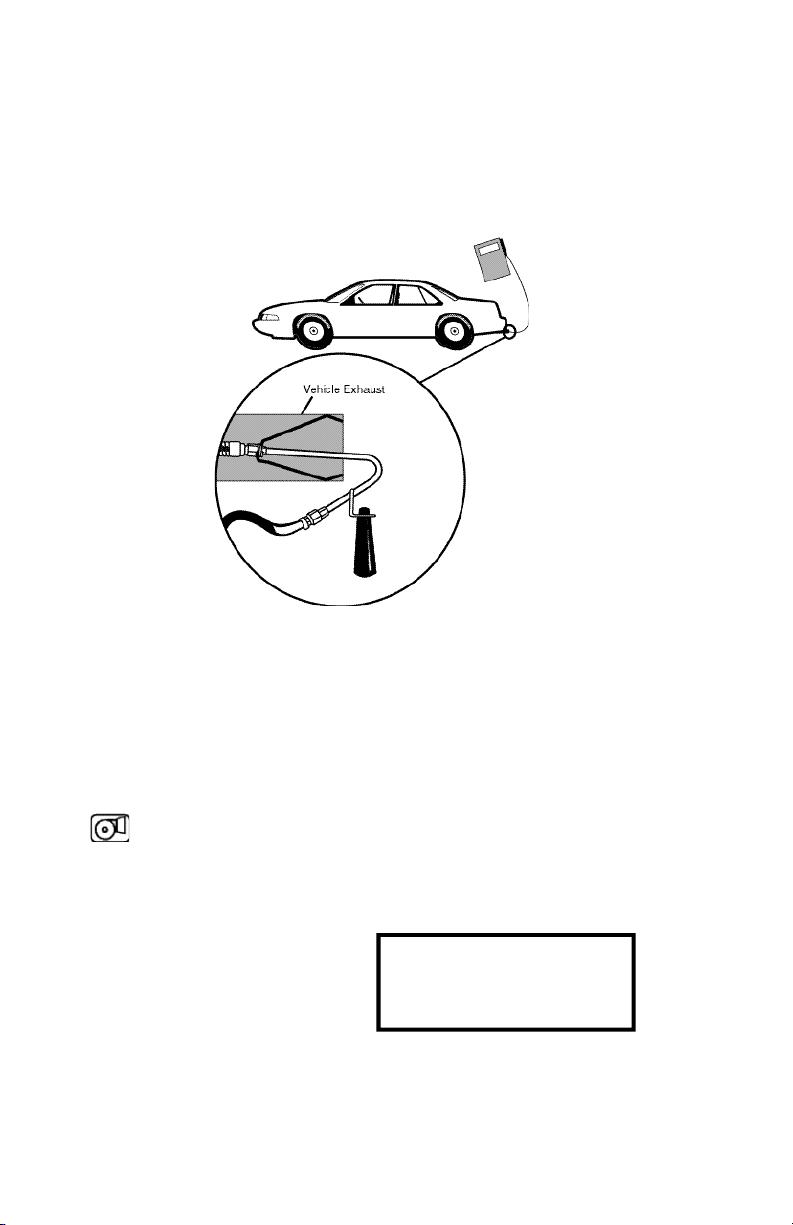
4.4 Sampling the Exhaust Gas
Once the zero calibration and test procedures have been completed and the fuel has been selected (See
Section 5.2.2) the probe can be inserted into the desired vehicle exhaust.
Ensure the probe is inserted into the exhaust pipe so as to not allow air into the probe. The exhaust of a car
can pulse, especially at low RPM, drawing air in causing bad readings, ensure the flexible probe is fully
inserted and the clip attached to the exhaust pipe.
4.5 Turning the pump ON/OFF
The analyzer is fitted with a pump to draw gas from the vehicle exhaust. To conserve battery power, switch
off the pump when you are not taking a measurement. Gas values may drift slightly when the pump is
turned off but should return to zero when the pump is turned on again. Manually zero the analyzer if it does
not return to zero.
Use the key to turn ON and OFF the pump.
CERTAIN ANALYZERS ONLY
The analyzer will block readings while the pump is off and display ‘----‘ on all gas channels. It will also
display PUMP OFF every 30 seconds.
It is recommended that the analyzer samples fresh air for at least 60 seconds before the pump is turned off.
9
PUMP OFF
HC ppm vol . . .- - - -
CO2 % vol . . . .- - - -
O2 % vol . . . .- - - -
Page 14

4.6 Taking an oil temperature reading (Certain analyzers only)
Connect the oil temperature probe to the instrument and check it reads ambient temperature. Turn off the
vehicle engine. Remove the oil dip stick from the engine and set the depth of the probe to that of the dip
stick using the stop. Insert the probe into the engine.
The oil temperature will be displayed :
4.7 Reading the engine speed (RPM) (Certain analyzers only)
Connect the induction pickup to one of the spark plug leads ensuring the side indicated by ‘SPARK PLUG SIDE’
points to the spark plug. Connect the pickup to the instrument ensuring correct polarity, "+" to red and "-" to
black. Set 4 cycle/2 cycle or DIS as detailed in section 5.2.2.
NOTE: If the pickup is positioned close to other leads false readings may occur. For some types of ignition
system (eg DIS) the probe may need to be fitted "reversed" to produce readings.
4.8 Regular Checks During Sampling
Care must be taken at all times not to exceed the analyzers operating specifications, in particular ensure
the following :
• DO NOT PLACE THE INSTRUMENT IN THE ENGINE BAY.
• The analyzer is not exposed to temperatures outside its normal operating range.
• DO NOT PLACE THE INSTRUMENT ON A HOT SURFACE.
• Liquid in the water trap does not go over the level indicator. Note! The indicator only works
while the trap is vertical. Water condenses in the probe line and can quickly fill the water trap
when the probe is moved. Take care, watch the water trap closely and empty any water when
it is noticed.
• The in-line particle filter is clean and does not become blocked. If this filter is allowed to
become dirty then damage may occur inside the analyzer.
• Do not start up or zero the unit in an area exposed to exhaust gas emissions.
1 0
LAMBDA . . . . . . . . . . . . . . .0.000
NO PPM . . . . . . . . .NOT FITTED
TIME TO ZERO . . . . . . . . . . . . . .10
OIL DEG C . . . . . . . . . . . . .50
RPM . . . . . . . . . . . . . . . . . . .0000
CO % VOL . . . . . . . . . . . . .00.00
HC PPM VOL . . . . . . . . . . .0000
O2 % VOL . . . . . . . . . . . . .20.90
Page 15

1 1
4.8.1 Low Flow
During sampling or at any time the pump is running the screen may display LOW FLOW. This is an indication
of the following:
• The particle filter needs replacing (a visual check is also necessary)
• Probe or tubing is blocked.
• Internal filters are blocked (Contact service agent)
WARNING! Under severe conditions of low flow the PUMP will stop and an audible tone will be heard.
The following screen shows the action to be taken:
Check the following for water:-
• Probe line, water trap and particle filter
When the blockage is cleared the instrument should resume normal operation. If it is not possible to clear the
problem then internal damage may have occurred and the unit should be returned to a service center.
4.9 Normal Shutdown Sequence
DO THIS EVERY TIME YOU USE THE ANALYZER
Remove the probe from the vehicle exhaust - TAKE CARE ! THE PROBE WILL BE HOT - and allow it to cool
naturally. Do not immerse the probe in water as this will be drawn into the analyzer and damage the pump
and sensors.
Once the probe is removed from the exhaust allow the readings to return to zero and press
the analyzer will count down from 30 to switch off.
If you have not finished but press by mistake, you can press to return to normal operation
and not switch OFF.
LOW FLOW
EMPTY WATER TRAP
CLEAR HOSE AND PROBE
THEN PRESS ENTER
OFF 30
MENU TO ESCAPE
Page 16

5. MOVING THROUGH THE MENUS
5.1 Basic Operation
From the MAIN DISPLAY
Press
to access the MAIN MENU
Press and
to move cursor up and down
Press
to access selected Menu
Press
to access selected Menu
Press and
to move cursor up and down
Press
to enter value and move to next
parameter
Press
to save settings and return to the
MAIN MENU
Press
to return to the MAIN DISPLAY
1 2
CO % vol . . .00.00
HC ppm vol . . . .0000
CO2 % vol . . . .00.00
O2 % vol . . . .20.90
MAIN MENU
1. SELECT 3. DISPLAY
2. UNITS 4. SETUP
MAIN MENU
1. SELECT 3. DISPLAY
2. UNITS 4. SETUP
MAIN MENU
1. SELECT 3. DISPLAY
2. UNITS 4. SETUP
SET :ZERO
FUEL :GASOLINE
RPM :4 CYCLE
CAL :CHECK
SET :ZERO
FUEL :GASOLINE
RPM :4 CYCLE
CAL :CHECK
SET :ZERO
FUEL :GASOLINE
RPM :4 CYCLE
CAL :CHECK
MAIN MENU
1. SELECT 3. DISPLAY
2. UNITS 4. SETUP
Page 17

1 3
5.2 Menu Options and Settings
5.2.1 Main Menu
The MAIN MENU consists of 4 sub menus which are shown below and detailed on the following pages.
All sub-menus are accessed using and exited using
The and keys move the cursor within a menu and allow parameters to be changed.
TIP Holding down one of these keys scrolls through the data quicker.
5.2.2 Select Menu
This menu allows selections to be made for the parameters detailed below.
OPTIONS
SET: ZERO
HC RESIDUE
LEAK
CHECK
FUEL: GASOLINE
LPG
CNG
RPM: 2 STROKE
4 STROKE
/12,/8,/6,/5,
/4,/3,/2
MAIN MENU
1. SELECT 3. DISPLAY
2. UNITS 4. SETUP
SET :ZERO
FUEL :GASOLINE
RPM :4 CYCLE
CAL :CHECK
Allows manual activation of zero setting, HC residue and leak
checking functions. More details on these functions can be
found in Section 10 - Zero checks and re-calibration
Select the fuel the vehicle is using from a standard fuel stored
in the analyzer. Select from:
To allow the analyzer to determine the correct revolutions per
minute of the engine it must know if it is a 2 or 4 stroke (use
2 stroke for DIS systems) when using the inductive clamp.
Select the number of cylinders if connecting to the low tension
side of the coil. Eg. /12 (test leads are optional)
Page 18

1 4
CAL: Allows the user to check the calibration of the analyzer using precision calibration test gases. It is
recommended this is done every 3 months. Test gas is available from your service centre. The
following can be performed in this menu:
• Set the calibration test GAS VALUE in the analyzer.
• CHECK the calibration accuracy against the test gas.
• RESET calibration values to factory settings.
Use the or to select from the
following functions. Press to select.
Details for performing the above functions can be
found in Section
10.4 – Gas calibration verification.
5.2.3 Units Menu
Allows the vehicle registration number to be changed and all displayed units to be changed.
Vehicle Registration Data
Allows the vehicle registration number to be entered. The format for the data is 8 characters alphanumeric
as follows:
1234567890:;<>?@ABCDEFGHIJKLMNOPQRSTUVWXYZ/space/
The cursor T indicates this character can be changed. Select the correct character from the list using
and press when correct.
Repeat until all the vehicle registration is correct .
GAS VALUE
CHECK
RESET
DATA :T123 ABC
TEMP :C
EFF :LAMBDA
PEF :0.512
DATA :T123 ABC
TEMP :C
EFF :LAMBDA
PEF :0.512
Page 19

1 5
TEMP: Choose selections from Centigrade ˚C or Fahrenheit ˚F. (Certain analyzers only)
EFF: Changes the calculation used in the Lambda calculation. Change from LAMBDA to AFR.
Formulas used in the analyzer are detailed in appendix B.
PEF: Propane equivalence factor or n-hexane to propane ratio as set in the instrument. This is not a
user variable parameter but is displayed for reference.
5.2.4 Display Menu
Allows the configuration of the display to be changed.
LIGHT :OFF
MODE :8-PAGE
CONTRAST :DEFAULT
LANGUAGE :ENGLISH
Turns the backlight ON or OFF.
Select 4 or 8 Page Mode or Line Scroll Mode as detailed in
section 4.3 Main Displays.
The contrast is set to a DEFAULT value or can be adjusted
LIGHTER or DARKER. Use the or key to adjust.
Note the display may jump from dark to clear.
Changes the analyzers displayed and printed language.
LIGHT:
MODE:
CONTRAST:
LANGUAGE:
ON
OFF
4 PAGE
8 PAGE
LINE
ENGLISH
SPANISH
DUTCH
FRENCH
ITALIAN
GERMAN
Page 20

1 6
5.2.5 Set-Up Menu
The set up menu allows the following parameters to be set / altered.
• Format of the date.
• Time
• Printout Header
The screen above shows the standard header setting with the cursor now shown underlining the U in UEI. By
using and any letter or number can be chosen.
Once the correct character is displayed, use to move right to the next. Move along until all characters
spell the desired name or phone number. If you need to go back and change a character use to
move left.
Press to return to the SET UP menu.
FORMAT :DD-MM-YY
DATE :02-03-99
TIME :09-10-31
HEADER :NO
Changes the date format set on the analyzer. Contact your
service center if this is incorrect.
Allows the user to change the date. Change each number of
the day, month and year until correct.
Allows the user to change the time. Change each number of
the hours and minutes until correct, the seconds will reset to
zero automatically.
Allows two lines of 20 characters to be programmed into the
analyzer. The header appears on the top of the standard
printout. This can be used to print your company name and/or
phone number.
FORMAT:
DATE:
TIME:
HEADER:
DD-MM-YY
MM-DD-YY
YY-MM-DD
Change each
number using
and
Change each
number using
and
NAME/PHONE
UEI
1-503-644-8723
'LEFT' USE STORE KEY
Page 21

1 7
6. PRINTING INFORMATION - OPTIONAL EXTRA ONLY
Supplied as an accessory for the analyzer is an infra-red thermal printer. Read the manual supplied with the
printer prior to operation. Connections to the analyzer are detailed below:
• Infrared thermal printer - this does not require a cable to transmit the data but uses an
infra-red (IR) link similar to a TV remote control. The IR emitter is positioned on the top of the
Analyzer and the bottom of the printer. Ensure they are pointing at each other and within
300 mm, with no obstructions in the way. Data may be lost if transmission is interrupted,
a black square is evidence of this. Keep the Analyzer pointing at the printer until the printout
has finished.
Data can either be printed from a ‘live’ test or from stored data. Printing of stored data is detailed in
STORING AND RETRIEVING DATA.
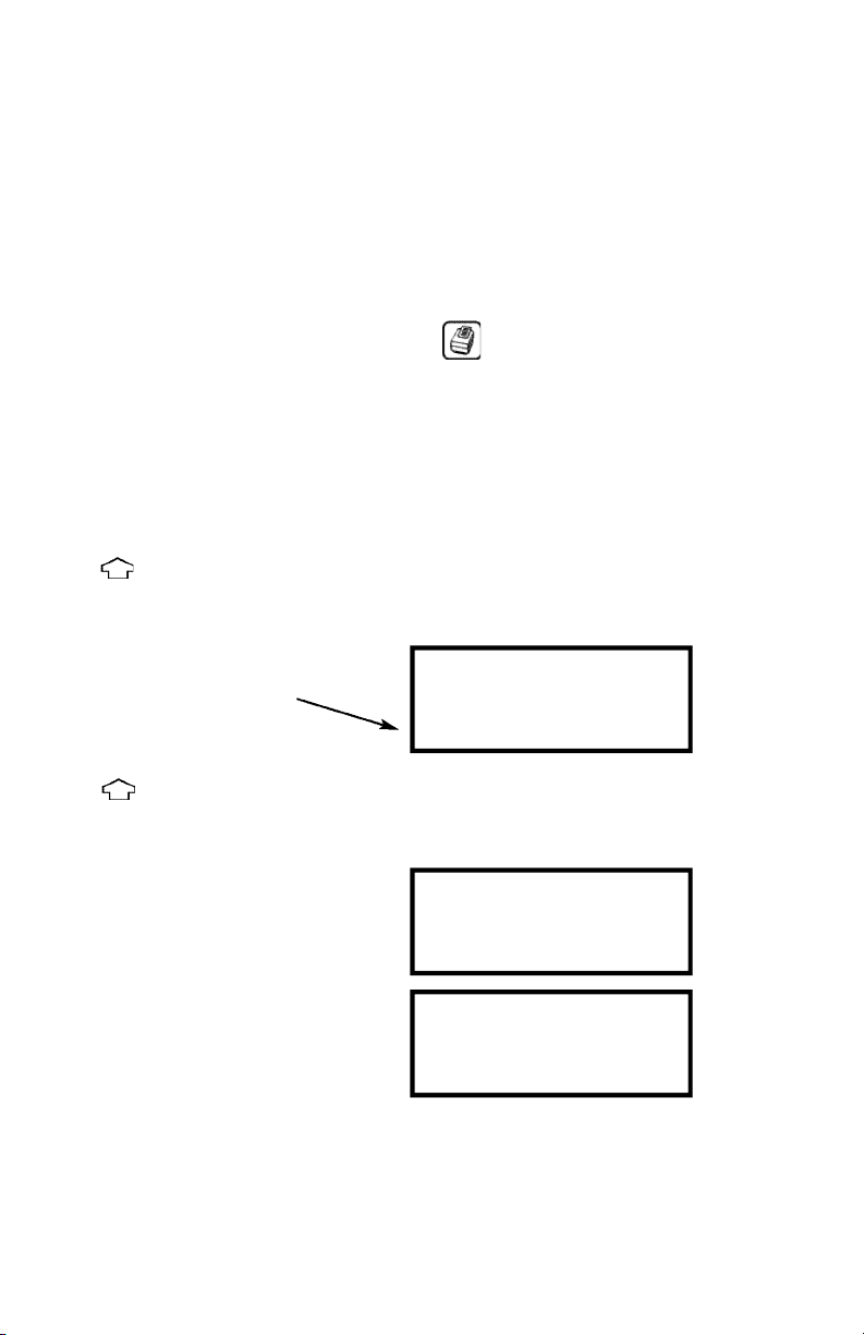
6.1 Printing a Live Test
During a vehicle test the Analyzer will print data on request. With the analyzer showing the MAIN DISPLAY
press and hold until the second beep. Current data will be sent to the printer. If the print button is held
until the third beep, the test results will be printed in duplicate (from software version 4.6).
The display will show the following until data transmission is complete.
6.2 Standard Printout
The standard printout is shown below :
****PRINTING****
UEI
1-503-644-8723
VEHICLE: T123 ABC
FUEL: GASOLINE
DATE: 17-03-99
TIME: 09-10-31
CO % VOL . . . 3.5
HC PPM VOL . . . 1234
CO2 % VOL . . . 14
O2 % VOL . . . 2.1
LAMBDA . . . 1.010
NOX PPM VOL . . . N/F
Page 22

1 8
7. STORING AND RETRIEVING DATA
The Analyzer can store up to 255 emissions tests. Once stored, the data can be viewed on the display or
downloaded to a printer.
7.1 Storing a Live Test
While performing a test and viewing the data on the MAIN display access the STORE menu as follows:
Mode: Select from the following:
• STORE - Allows data to be stored in memory.
• VIEW / PRINT - Stored data can be viewed or printed.
• DELETE - Clears all data in memory.
• AUTO STORE – Automatically stores data at a preset interval.
Location: Automatically allocates a location in the memory of the instrument for the next test. On the
display shown above the next location will be 3.
To store a test, set MODE to STORE and press . The current readings will be stored in the
analyzers memory.
NOTE: The analyzer will stop logging once it has reached 255 readings and will return to the main display if
the store key is pressed. Data can still be viewed and printed.
TIP: Make a note of the location number for your particular test as it may be useful when printing.
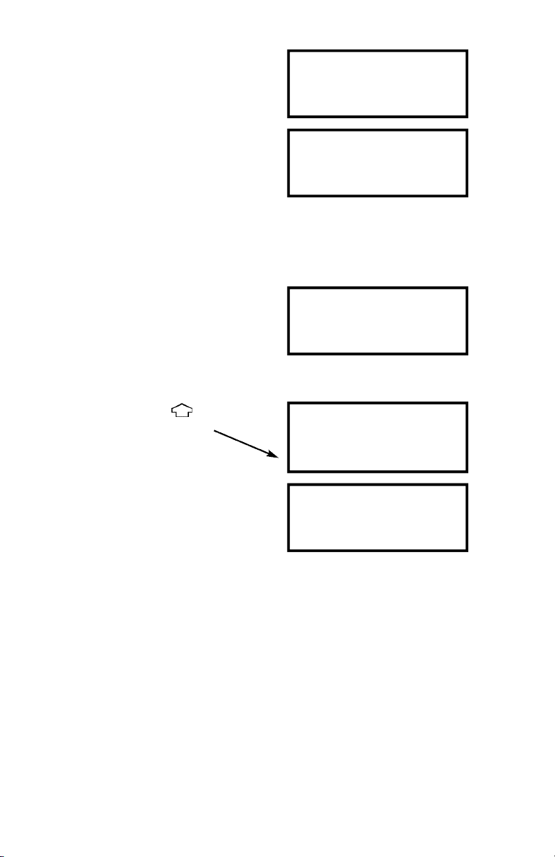
7.2 Viewing and Printing a Stored Test
Press
to access the STORE MENU
STORE MENU
MODE : STORE
TEST : 3
PRESS 'STORE' TO LOG
STORE MENU
MODE : VIEW/PRINT
TEST : 001 TO 010
PRESS 'ENTER' TO VIEW
Page 23

1 9
Move the cursor to Location and press . The cursor will move to the first digit of the first number,
use to select the correct digit and enter when correct. Repeat on the second digit until the location to
view from is correct.
Press to move the cursor to the second number, select the last location to view using the
same procedure.
To view the stored data press:
Use and to page through data as in MAIN DISPLAYS.
Press to advance to the next test.
Press to go back to the previous test. Press to return to the MAIN MENU.
A printout of the test being displayed can be obtained by pressing
TEST ... 1
VEHICLE T123 ABC
DATE ... 07-08-96
TIME ... 12:31:35
TEST ... 1
FUEL
GASOLINE
CO % VOL ... 00.00
HC PPM VOL H ... 0000
TEST ... 1
O2 % VOL ... 20.90
CO2 % VOL ... 00.0
LAMBDA ... 0.000
TEST ... 1
AFR ... 00.00
NO PPM NOT FITTED
TEST ... 2
VEHICLE P456 DEF
DATE ... 07-08-96
TIME ... 13:31:10
Page 24

2 0
TIP: Stored and displayed with the data are actual time and date of the test.
7.3 Deleting Data
To delete the data in stored memory press to obtain the STORE MENU (as above)
Press to access the STORE MENU
Press to access delete data screen
Press to delete data in memory, press to exit delete data screen.
WARNING! ALL DATA WILL BE REMOVED
Ensure you have printed the data you require before clearing the memory.
STORE MENU
MODE : DELETE
TEST : 3
PRESS 'ENTER' TO DELETE
ENTER TO ERASE DATA
MENU TO ESCAPE
Page 25

2 1
7.4 Auto Store
Press to enter Auto Store Mode.
Press or to change the interval between Auto Stores (interval can be set between
10 and 99 secs).
Press to initiate Auto Store sequence.
During the Auto Store sequence the store number appears on the top line of the display, accompanied by a
double beep.
To disable Auto Zero store mode:
Press .
Then press .
Press to escape.
STORE MENU
MODE : AUTO STORE
TEST : 10 S
PRESS 'ENTER'
STORE MENU
MODE : AUTO STORE
TEST : 1 0 S
PRESS 'ENTER'
STORE MENU
MODE : STORE
TEST :
PRESS 'ENTER' TO LOG
Page 26

2 2
8. MAINTENANCE
8.1 Emptying and Cleaning the In-Line Water Trap
While performing a test and viewing the data on the MAIN display access the STORE menu as follows:
The in-line water trap should be checked and emptied on a regular basis. Water vapor will condense and
gather in the probe line. This may move suddenly to the trap when the probe is moved. Care should be taken
at all times.
Emptying of the water trap is detailed below:
Water level indicator (do not exceed level while trap is vertical)
Carefully remove the end cap from the in-line housing. Dispose of the condensate in a suitable drain. Clean
the inside of the water trap using a soft cloth
8.2 Changing the Particle Filter
This is a very important part of the analyzer and should be changed regularly. It prevents dust and dirty
particles entering the pump and sensors and hence causing damage. The filter MUST be changed when it is
discolored or if LOW FLOW is indicated and no obvious fault can be found.
Remove the end cap from the in-line filter housing. Carefully remove the paper filter element and dispose of
it. Clean the inside of the filter housing with a suitable soft cloth. Insert a new filter element onto the spigot in
the filter housing and carefully replace the end cap.
IF THE FILTER IS NOT CHANGED REGULARLY DAMAGE WILL OCCUR TO THE SENSORS RESULTING IN A
CHARGEABLE SERVICE. IT IS EVIDENT FROM AN INTERNAL INSPECTION OF THE INSTRUMENT IF THE FILTER HAS
BEEN CHANGED REGULARLY.
Page 27

2 3
9. PROBLEM SOLVING
The following is a list of problems that may occur on the instrument through its operating life. If the cause of
the fault is not easy to identify then we advise you contact UEI International Technical Support or an
International Distributor for expert advice.
INTERNAL FILTER
To protect the analyzer from water ingress a filter is installed inside the casing to protect the infrared
measuring system. This filter will block if care is not taken during sampling:
• Ensure any build-up of water in the probe line and water trap are removed as soon as possible.
• The external particle filter is changed regularly.
• The instrument is allowed to sample fresh air on a regular basis.
• The instrument samples fresh air for 3 minutes before switch off.
• Do not blow smoke from a cigarette into the instrument, the tar will clog the filter
and the unit will need to be sent in for service.
Fault symptom
• Oxygen too high
• Oxygen Error (FAULT)
• Infrared gas Error (FAULT)
• Analyzer not holding charge
• Analyzer not charging
• Analyzer does not respond to exhaust gas
• Oil temperature readings erratic
• Analyzer automatically switches off in
operation
Causes
• Air leaking into probe, tubing, water trap,
connector or internal to instrument.
• Oxygen cell needs replacing.
• Zero calibration fault
• Instrument has been stored in a cold
environment and is not at normal
working temperature.
• Oxygen cell or infrared bench needs replacing.
• Battery exhausted.
• Charger not giving correct output.
• Fuse blown in charger plug.
• Particle filter blocked.
• Probe or tubing blocked.
• Pump not working or damaged with
contaminant's.
• Temperature plug reversed in socket.
• Faulty connection or break in cable or plug.
• Battery below alarm level.
• Ambient temperature above 50∞C.
• Battery quickly discharging and is faulty.
Page 28

2 4
If you suspect the internal filter is blocked perform the following:
• Remove the probe connection from the water trap.
• Empty and clean the water trap with a dry cloth.
• Fit a new external particle filter.
• Run the instrument in fresh air (pump ON) for at least one hour.
If the problem does not clear contact a service agent.
10. ZERO CHECKS AND RE-CALIBRATION
During normal operation of the analyzer the following checks may be requested as required:
• Zero setting of all sensors (can also be selected manually)
• HC residue check (automatic) Certain analyzers only.
• Leak test
• Calibration check.
• Re-calibration.
10.1 Zero Setting
The zero setting function sets the working sensors to zero using fresh air. This function is activated as follows:
• Following analyzer switch ON.
• On a timed basis. Following the analyzer first being turned ON a zero will requested
automatically at 7, 15 and then 30 minute intervals. Subsequent requests will be
every 30 minutes.
• On request by the user from the SELECT MENU
The zero sequence is as follows, ensure the on screen commands are followed or the analyzer may not
zero correctly.
Ensure the probe is removed from the vehicle exhaust and is sampling fresh air, in the garage environment
this should be 45 meters or 18 inches above the ground. Once this is done press to activate the pump.
WARNING! The sensors will only be reset if the probe is sampling fresh air for at least 60 seconds.
Once the zero is complete the screen will return to the MAIN DISPLAY.
If the analyzer fails to zero it may request a HC residue check. (Certain analyzers only)
ZERO CHECK
REMOVE PROBE
FROM EXHAUST
THEN PRESS ENTER
Page 29

2 5
10.2 HC residue check (Certain analyzers only)
Hydrocarbon is a very ‘sticky’ gas and can cling to tubing in the analyzer or probe. If HC % vol reading does
not go below 20 ppm when in fresh air following a test then a residue check will be requested. Repeat tests
will be carried out until the reading is below 20 ppm.
The HC residue check procedure is as follows:
As instructed remove the probe from the exhaust and detach the water trap and particle filter housing from
the instrument. Fit the carbon filter element in place of the water trap housing, press when in place.
NOTE! The analyzer will not continue with the test if it does not detect the carbon filter element is
in place. Use of the analyzer is prohibited if the filter is not used and a successful HC residue
check not completed.
During this check it is advisable to perform the following maintenance:
• Change the particle filter and clean the inside of the housing.
• Clear the probe line using a compressed air line. Note! This must only be done with the probe
removed from both analyzer and vehicle.
If the analyzer cannot detect a reduction in the HC level to within preset limits then it will try again from the
screen shown above. If the analyzer continues to fail the test contact your service agent for advice.
If the HC residue check is successful the following screen will be displayed.
Once the check is complete the screen will return to the MAIN DISPLAY. Remove the carbon filter element
and store in the instrument case. Reconnect the water trap housing and probe.
HC RESIDUE CHECK
REMOVE EXHAUST PROBE
FIT CARBON FILTER
THEN PRESS ENTER
HC RESIDUE CHECK
PASSED
REMOVE CARBON FILTER
THEN PRESS ENTER
Page 30

2 6
10.3 Leak Check
To ensure the gas sampling system is sealed correctly and not letting in air, the analyzer will perform a leak
check. This requires the user to block the probe inlet and perform the test. This check is done every time the
analyzer is switched on or as requested by the user. It is also advisable to perform a leak check if the water
trap is removed and replaced i.e. for particle filter renewal.
When YES is selected, the leak check procedure is as follows:
CAUTION! When fitting the SEAL ensure the exhaust probe has been removed from the vehicle for
some time and is cool.
Press when the seal is in place. The check will take a few seconds. Following a successful test the
analyzer will return to the MAIN DISPLAY.
If a leak is detected in the gas system the test will fail.
Check for the following:
• The seal is correctly positioned over the holes in the end of the probe.
• There are not apparent cracks in the probe or tube.
• The water trap housing is not cracked and the ends are in place.
• All O-rings on the probe connections are in good condition and in place.
• There is no physical damage to the analyzer case.
• The water trap fitting on the analyzer is in good condition.
Once the above has been checked press to perform the leak test again.
If the analyzer continues to fail, contact your service center.
LEAK CHECK
REMOVE EXHAUST PROBE
FIT PROBE SEAL
THEN PRESS ENTER
LEAK CHECK
PASSED
REMOVE PROBE SEAL
THEN PRESS ENTER
LEAK CHECK
FAILED
CHECK PROBE & SEAL
THEN PRESS ENTER
Page 31

2 7
10.4 Gas Calibration Verification
This section details using precision calibration gases to check the analyzer settings. It does not replace an
annual calibration and service by an authorized agent.
Access to the calibration functions are found in menu 1. SELECT, sub menu CAL.
10.4.1 Calibration Gas Values
To allow the analyzer to check its calibration it must know the values of calibration gas contained in the
bottle. Select GAS VALUE in the menu shown above. Pressing will access the following screen:
Enter the gas values as shown on the calibration gas bottle. Note CO and CO2 are expressed in percentage %,
HC is ppm propane and NOx in ppm. Setting each number is as detailed Set Up Menu (Section 5.2.9). Once
the values are correct press the key to save the data and exit.
Note! If you do not have a NOx sensor fitted to your analyzer then you will not need to enter a gas value.
N/F will be displayed.
HC - HydroCarbon readings
During the calibration routine HC readings will be expressed as n-hexane even though the gas bottle will
contain propane. It is important to understand that when entering the HC gas value into the analyzer the
value on the calibration gas bottle is entered. In our example 2000 ppm propane.
When performing a calibration reading or check the analyzer will automatically convert the readings using
the PEF and express them as n-hexane.
Using the PEF detailed on page 15 of this manual the analyzer would display:
HC displayed reading (n-hexane) = 2000 ppm x PEF
= 2000 x 0.512 = 1024 ppm
FUEL : GASOLINE
RPM : 4 STROKE
ZERO : NO
CAL : GAS VALUE
GAS VALUE
CO : 3.50 CO2 : 14.0
HC : 2000 NOX : 1000
'LEFT' USE STORE KEY
Page 32

2 8
10.4.2 Calibration Check
You should perform a calibration check when ever you suspect an error or at a minimum of 450 hours. Select
CHECK from the screen above and press
The instrument will request a ZERO CHECK, see Section 10.1, once complete, proceed as follows:
WARNING! Use calibration gas in well ventilated areas. Fumes may cause nausea and headaches.
Connect the calibration gas to the water trap connection on the analyzer using the hose provided.
Important: To prevent damage to the analyzer, be sure to use the pressure regulator
between the analyzer and the gas bottle. Read the instructions supplied with the calibration
gas carefully.
Open the gas valve on the calibration bottle. The following screen will display the change in gas values as the
analyzer detects the calibration gas.
The instrument will automatically perform a gas check within 60 seconds. The number 30 will countdown to
give an indication of calibration status. Messages on the screen as follows:
• CONNECT GAS when the analyzer is waiting for calibration gas to be applied.
• NO GAS DETECTED will be displayed after 30 seconds if the instrument does not see changes
in the gas values. Check the gas valve has been opened, the fittings are secure and that there is
sufficient pressure in the bottle. Fails test and returns to main screen.
• DETECTING GAS when the analyzer has started to read calibration gas and is stabilizing –
normally within about 5-10 seconds.
• GAS UNSTABLE message is displayed after the instrument has detected gas for 30 seconds
but readings fluctuate. Fails test and returns to main screen.
FUEL : GASOLINE
RPM : 4 STROKE
ZERO : NO
CAL : GAS VALUE
CALIBRATION CHECK
CONNECT CAL GAS
THEN PRESS ENTER
CALIBRATION CHECK
CO : 3.50 CO2 : 14.0
HC : 2000 NOX : 1000
CONNECT GAS 30
Page 33

2 9
Once the analyzer has detected a stable gas supply it will check that all the gas readings are within the
allowable deviation from the factory calibration. If the readings are within these limits it will proceed to the
next section 10.4.3 User Re-calibration.
Note! Disconnect gas at this time.
If the analyzer falls outside these limits it is in need of repair and should be returned to an approved service
agent. The following screen will be displayed.
The analyzer checks all measured gases and if one or more fail it will indicate a fault. An option to print a
calibration report is given at this time.
10.4.3 User Re-calibration
Following a successful calibration check you will be informed of the following:
Gas calibration is within specification.
A printed report can be obtained.
Gas calibration is outside specification
and need adjustment.
Following both options detailed above you will be allowed to reset the analyzer calibration constants:
Selecting NO keeps the last calibration and returns to the main menu. To alter the calibration constants select
YES to access the following screen.
FAILED FACTORY
CALIBRATION CHECK
UNIT MAY NEED REPAIR
PRINT REPORT NO
DISCONNECT GAS
CALIBRATION VERIFIED
PRINT REPORT NO
DISCONNECT GAS
CALIBRATION ADVISED
PRINT REPORT NO
CALIBRATE: NO
ENTER SERVICE CODE
0 0 0 0
Page 34

3 0
Before the new calibration can be accepted an authorization code is required.
Enter each number of the code 5128.
Once the last digit has been entered the analyzer will store the new settings into its memory, this may take a
few seconds and you will be asked to PLEASE WAIT. Once the memory settings have been checked the
analyzer will display:
Select to either run a final calibration report or not before returning to the main menu.
If in any doubt about the calibration of the analyzer contact a service centre.
10.4.4 Printed Calibration Report
During all stages of the calibration routine you will be asked if you would like to print a calibration report.
See section 6.1 for details on printing.
The calibration report is shown below
ENTER SERVICE CODE
5 1 2 8
CALIBRATION RESET
PRINT REPORT NO
UEi
Calibration Report
Version 2.4
Date: 07-08-01
Time: 09:10:31
Max: 14.7
CO2 % vol: 13.6
Min: 13.3
Max: 3.68
CO % vol: 3.63
Min: 3.32
HC CAL Gas: 2000
PEF: 0.512
Max: 1075
CO2 % vol: 1024
Min: 973
Max: 1050
CO2 % vol: 1006
Min: 950
AMB deg: 24.4
PRS mbar: 1068
Page 35

Information contained on the calibration report is as follows:
• VERSION: Analyzer software version
• CO, CO2, HC, O2, NO: Gas readings as measured during check.
• MAX / MIN: Upper and lower limits at which calibration check fails and recalibration is advised.
• AMB deg: Ambient temperature reading during calibration
• PRS mbar: Ambient Pressure reading during calibration
If the gas reading does not fall between the MAX and MIN limits then the analyzer has failed a
calibration check.
AMB and PRS can be used when discussing problems with a service agent.
10.4.5 Reset Instrument Calibration
This feature allows the analyzer to be reset to the factory setting if an error occurs during a user calibration.
This may occur, for example, if the calibration gas bottle runs out during calibration or the instrument stores
the values incorrectly. Note this routine should only be used if a calibration failure is suspected.
Select RESET from the screen above and press
To reset the calibration values to those originally set in the factory or at the last analyzer service the correct
code needs to be entered.
DO NOT ENTER THIS CODE UNLESS YOU SUSPECT THE ANALYZER CALIBRATION SETTINGS
HAVE BEEN LOST OR CORRUPTED.
FACTORY CALIBRATION RESET CODE: 7378
FUEL : GASOLINE
RPM : 4 STROKE
ZERO : NO
CAL : RESET
CALIBRATION RESET
ENTER SERVICE CODE
0 0 0 0
CALIBRATION RESET
ENTER SERVICE CODE
7 3 7 8
3 1
Page 36

32
Enter each digit of the code as explained in Set Up Menu (Section 5.2.5). Once the last digit has been entered
the factory settings will be restored and the analyzer will return to the main display. A calibration check
should now be performed.
If the wrong code is entered the analyzer will exit to the previous menu without restoring the factory settings.
11. PRODUCT SPECIFICATION FOR AUTO2-2
*1
Using dry gases at STP
To obtain the quoted specification an instrument should be calibrated with clean ambient air (normally outside
the workshop) at standard temperature and pressure (STP).
Note: The analyzer is not for use with a Dynamometer, unless the high temperature probe is fitted.
NDIR means by non-dispersive infrared principle.
Parameter Resolution Accuracy Range
Carbon Monoxide 0.01 % +/- 10 % of reading
*1
0-10 %
(CO)(Infrared - NDIR) +/- 0.2 % volume
*1
Over-range 20 %
Hydrocarbon 1 ppm +/- 10 % of reading
*1
0-5000 ppm
(HC - hexane)(NDIR) +/- 30 ppm volume
*1
Over-range: 10,000 ppm
CO & HC OIML R99 Class 2
Oil Temperature 0.1˚C/F ±2.0˚C ±0.3% or reading 0-150˚C
±3.6˚F ±0.3% of reading 32-302˚F
RPM 1 rpm 50 rpm 200-6,000 rpm. 2 or 4 stroke engines.
Inductive clamp or low tension connections.
Additional features Specifications
Sensor response T
95
Nominal response time
of 20 seconds
Warm up Less than 3 minutes
Pre-programmed Fuels Gasoline, LPG and CNG
Data-Logging 255 Snap Shots
PC Connections Via RS 232 port
Dimensions
Weight 1Kg
Handset 220mm x 55mm x 120mm
Probe Insertion depth 350mm x Diameter 15mm
Clip handle to secure to exhaust, 4m long hose
Various probes available including high temperature
Ambient Operating Range +5˚C to 45˚C/10% to 90% RH non condensing
Storage temperature Minimum: 0˚C
Maximum: +50˚C
Battery Charger Input: 110 Vac/230 Vac nominal
Output: 10 Vac off load
Analyzer battery run time >4 hours from full charge with the pump running
Page 37

33
PRODUCT SPECIFICATION FOR HANDHELD AUTO4-2 AND AGA5000
*1
Using dry gases at STP
*_ Standard on models AGA5000 only
To obtain the quoted specification an instrument should be calibrated with clean ambient air (normally outside the workshop) at standard
temperature and pressure (STP).
Note: The analyzer is not for use with a Dynometer, unless the high temperature probe is fitted.
Parameter Resolution Accuracy Range
Carbon Monoxide 0.01 % +/- 5 % of reading
*1
0-10 %
(Infrared) +/- 0.5 % volume
*1
Over-range: 20 %
Oxygen 0.01% +/- 5 % of reading
*1
0-21%
(fuel cell) +/- 0.1 % of reading
*1
Over-range: 48%
Hydrocarbon 1 ppm +/- 5 % of reading
*1
0-5000 ppm
(Infrared) +/- 12 ppm volume
*1
Over-range: 10,000 ppm
Carbon Dioxide 0.1% +/- 5% of reading
*1
0-16%
(Infrared) +/- 0.5% ppm volume
*1
Over-range: 25%
Nitric Oxide*_ 1 ppm 0-4000 ppm +/-4% or 0-5000 ppm
(fuel cell) 25 ppm; 4000-5000 ppm
+/-5%
Oil Temperature 1.0˚C/F ±2.0˚C ±0.3% of reading 0-150˚C
±3.6˚F ±0.3% of reading 32-302˚F
RPM 1 rpm 50 rpm 200-6,000 rpm
Carbon Monoxide 0.01% Calculated 0-15%
Corrected CO
Lambda 0.001 0.8 - 1.2
AFR (Gasoline) 00.01 11.76 - 17.64
(LPG) 00.01 12.48 - 18.72
Sensor response T
95
Nominal 20 seconds Auto4-2 and AGA5000
Warm Up Less than 3 minutes
Pre-programmed Fuels Gasoline, LPG and CNG
PC connection Via RS 232 port
Data-Logging 255 Tests
Dimensions
Weight 1kg
Handset 220mm x 55mm x 120mm
Probe Insertion depth 35mm x Diameter 15mm
Clip handle to secure to exhaust, 4m long hose
Various probes available including high temperature
Ambient Operating Range +5˚C to +45˚C/10% to 90% RH non condensing
Storage temperature Minimum: 0˚C
Maximum: +50˚C
Battery Charger Input: 110 Vac/230 Vac nominal
Output: 10 Vac off load
Analyzer battery run time >4 hours form full charge with the pump running
Page 38

34
APPENDICES
A - Main Display Parameters
The parameters and their meanings are detailed as follows:
FUEL: The selected fuel will be displayed, i.e. GASOLINE. See Select menu section 5.2.2 to change.
• GASOLINE – Leaded or Unleaded gasoline/gasoline.
• LPG – Liquid Petroleum Gas
• CNG – Compressed Natural Gas
DATE: Analyzer date. See Set-Up menu section 5.2.5 to change.
TIME: Analyzer time. Use Set-Up menu section 5.2.5 to change.
BATTERY: Displays the battery level from 0-100%. The analyzer will flash
(BAT) RECHARGE BATTERY at less than 10 % of charge. With the charger connected the display
shows AC ON.
NOTE! Allowing the battery to discharge fully may destroy it.
O2: Oxygen measured in the exhaust gas indicated in percentage %. With the pump off the
analyzer will display - - - -. If there is a fault with the oxygen sensor then FLT will be displayed.
CO: Carbon monoxide measured in the exhaust gas indicated in percentage %. With the pump off
the analyzer will display - - - -. If there is a fault with the CO reading then FLT will be displayed.
CO2: Carbon dioxide measured in the exhaust gas in percentage %. With the pump off the analyzer
will display - - - -. If there is a fault with the CO2 reading then FLT will be displayed.
HC: Hydrocarbons measured in the exhaust gas indicated in ppm (parts per million) n-hexane
(gasoline). With the pump off the analyzer will display - - - -. If there is a fault with the HC
reading then FLT will be displayed.
COK: Generally known as corrected CO. This value is calculated and used for comparison with the
actual infra-red measured CO value. COK = (Cox15)/(CO + CO2), for normal car exhaust CO +
CO2 = about 15%. In this case CO is approximately equal to COK. If COK is clearly higher
than CO this indicates defects such as exhaust leaks. At near zero COK is not valid.
OIL: Oil temperature as measured by the dip stick probe. Displays in either ˚C (deg C) or ˚F (deg F)
and will display N/F if the probe is not connected.
Page 39

35
RPM: Revolutions per minute of the engine as detected by the induction pickup clamp. This probe is
plugged into the two connector on the bottom of the instrument case, ensure correct polarity. NOT
FITTED (N/F) will be displayed if the probe is not connected.
LAMBDA: The value of Lambda gives an indication of the burning efficiency of the engine. This can be
replaced with the Air Fuel Ratio (AFR) below. See Units Menu (Section 5.2.3) to change between
displays. Appendix B gives the formula used.
When sampling fresh air and lambda is outside operation range this indication will show ‘-----‘.
AFR: Air Fuel Ratio is another method for displaying the efficiency of an engine. The calculation for the
AFR is Lambda multiplied by 14.7 for Gasoline and 15.6 for LPG (typically). When sampling
fresh air this indication will show ‘-----‘.
NO: Nitric oxide reading in ppm (parts per millions) of the exhaust gas. Displayed when Nitric oxide
sensor fitted, indicated on the rear label. Displays NOT FITTED or N/F when sensor not fitted
and FAULT or FLT if failed.
NOx: A calculated value based on the measured level of Nitric Oxide to display total oxides of Nitrogen.
LOW FLOW: During sampling or at any time the pump is running the screen may display LOW FLOW.
PUMP OFF: Indicates the pump has been manually turned off using the key.
TIME TO: The analyzer requires to regularly zero the sensors. Once a zero has been performed the time to
ZERO the next zero is displayed in minutes. Check there is sufficient time remaining before starting a
test and perform a manual zero if not.
B - LAMBDA CALCULATIONS
The value for Lambda is a determinant for the burning efficiency of an engine. The value depends on the
composition of the fuel, the air that is used for the combustion and on the combustion products as found in
the exhaust gases.
This formula takes into account the following:
• Components of the fuel: carbon, hydrogen, oxygen and water content;
• Water content of the air;
• Components of the exhaust gases: carbon dioxide, carbon monoxide, hydrocarbons and
nitrogen oxide;
Developed by J. Brettschneider and published in Bosh Technishe Berichte, Volume 6 (1979), No. 4,
page 177-186.
Page 40

36
A simplified formula, derived from the basic formula, and based upon the assumption that the water content
of the fuel and air and the NOx content in the exhaust gases are negligible, allows the computation of
Lambda when certain components of the exhaust are measured.
B.1 Oxygen balance formula
For Lambda calculation, based upon measurements of CO, CO2, HC and O2, the following formula is
standardized: Displayed on the instrument as LAMBDA (O)
y = CO2+ (CO/2) + O2+ [HCV/4 x {3.5 / (3.5 + CO/CO2)} – OCV/2] x (CO2+ CO)
(1 + HCV/4 - OCV/2) x {(CO2+ CO) + (K1x HC)}
Where:
CO = Carbon monoxide % volume measured.
CO2= Carbon dioxide % volume measured.
HC = Hydrocarbon ppm volume measured.
O2= Oxygen % volume measured.
K1= Conversion factor for HC is expressed in ppm vol n-hexane (C6H14) equivalent. Its value in
this formula is 6.10-4
Hcv= Atomic ratio hydrogen to carbon in the fuel. Nominal value is 1.7261
Ocv= Atomic ratio oxygen to carbon in the fuel. Nominal value is 0.0176
C - Procedures for changing Oxygen fuel cell
The Oxygen fuel cell is housed within the case of the instrument. It should be changed at an approved service
centre when readings of oxygen are erratic or when the unit will not set to 20.9% following a zero.
Note! The oxygen reading in fresh air may drift between 20.7 and 21 % this is normal.
D - Electromagnetic Compatibility (CE) Statement
This product has been tested for compliance
with the following generic standards:
EN 50081-1
EN 50082-1
and is certified to be compliant
Page 41

Copyright © 2003 UEi Auto4-2/Auto5-2/AGA5000 MAN 7/03
Limited Warranty
The Auto 4-2 is warranted to be free from defects in materials and workmanship for a
period of one year from the date of purchase. If within the warra n ty period your instrument
should become inoperative from such defects, the unit will be repaired or replaced at UE i ’ s
option. This warra n ty covers normal use and does not cover damage which occurs in
shipment or failure which results from alteration, tampering, accident, misuse, abuse, neglect
or improper maintenance. Batteries and consequential damage resulting from failed
batteries are not covered by warra n ty.
Any implied warranties, including but not limited to implied warranties of
merchantability and fitness for a particular purpose, are limited to the express
warranty. UEi shall not be liable for loss of use of the instrument or other incidental or
consequential damages, expenses, or economic loss, or for any claim or claims for such
damage, expenses or economic loss. A purchase receipt or other proof of original purchase
date will be required before warra n ty repairs will be rendered. Instruments out of warra n ty
will be repaired (when repairable) for a service charge. Return the unit postage paid and
insured to:
1-800-547-5740 • FAX: (503) 643-6322
Service: (800) 308-7709
www.ueitest.com • Email: info@ueitest.com
This warranty gives you specific legal rights. You may also have other rights which vary from
state to state.
UE
Auto 2-2, Auto 4-2 & AGA5000
Gas Analyzer
®
 Loading...