

Unity Opto Technology MSL-154BV Datasheet
Surface Mount Chip LEDs
MSL-154BV
Description
FP
F
D
R
OPR
STG
OT
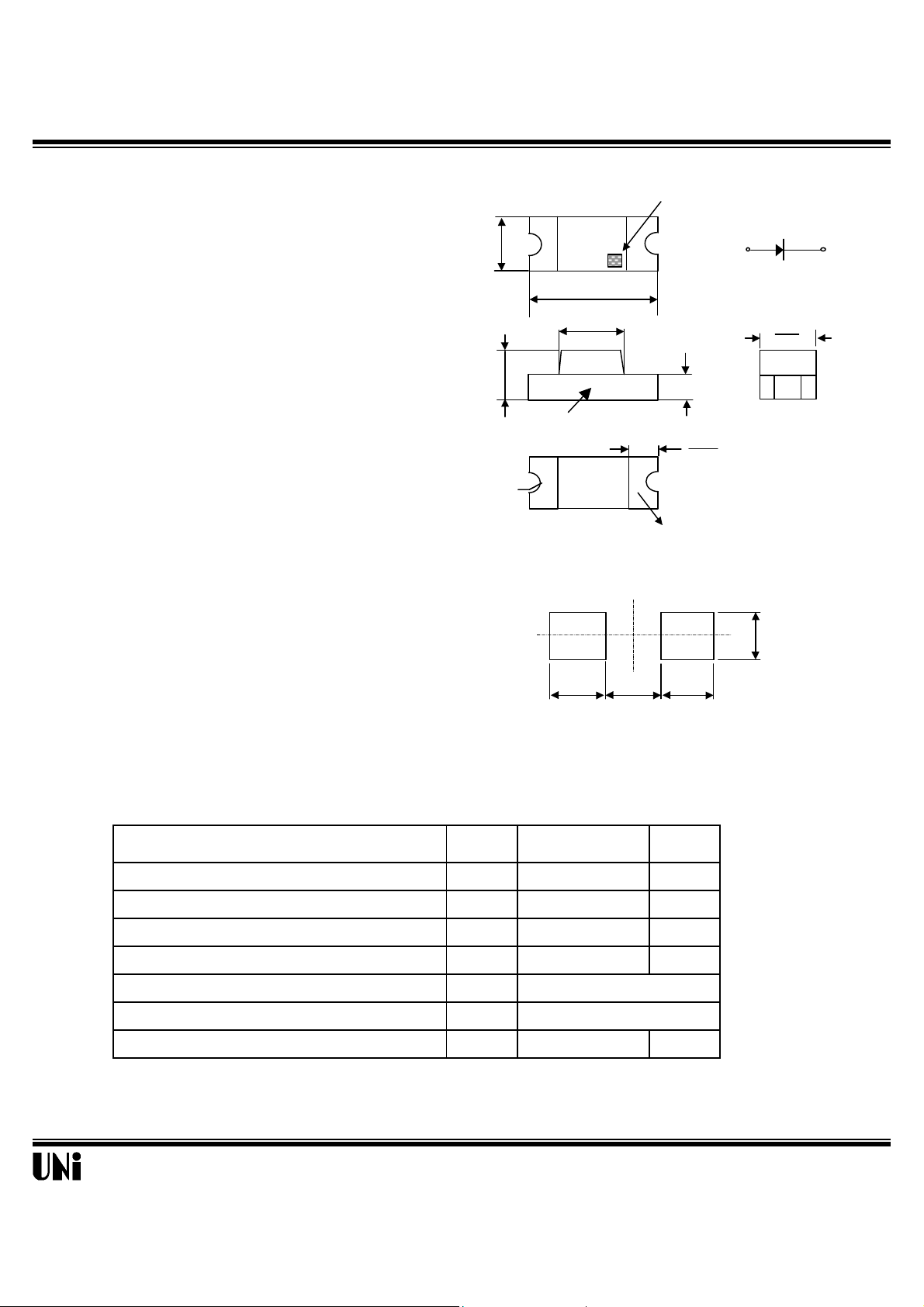
2. Tolerance is ± 0.1mm (.004") unless otherwise specified.
(0.059)
(0.059)
CATHODE MARK
( 0.020 )
(0.020)
TERMINAL
( 0.063 )
PCB
The MSL-154BV, a BLUE source Chip LED device,
is designed in an indnstry standard package suitable
for SMT assembly method. It utilizes GaN on SiC
LED chip technology and water clear epoxy package.
Applications
Package Dimensions
1.60
3.20
( 0.126 )
2.00
(0.079)
1.10
(0.043)
POLARITY
1.60
0.50
l Small Size
l Industry Standard Footprint(1206)
l Compatible with IR Solder process
l Availalble in 8 mm Tape on 7"(178mm)
Diameteer Reels
Features
l Push-Button Backlighting
l LCD Backlighting
l Symbol Backlighting
l Front Panel Indicator
Absolute Maximum Ratings
Parameter Symbol Maximum Rating Unit
Peak Forward Current(1/10 Duty Cycle@1KHz ) I
R0.4
(0.016)
SOLDERING
Recommended Solder Patterns
@ T
1.50
=25
A
1.50
2.0
(0.079)
NOTE:
1. All dimensions are in millimeter (inches)
70 mA
0.50
1.5
(.059)
o
C
DC Forward Current I
Power Dissipation P
Reverse Voltage V
Operating Temperature Range T
Storage Temperature Range T
Electrostatic Discharge Threshold E
Unity Opto Technology Co., Ltd.
30 mA
140 mW
5 V
o
-20
C to +80oC
o
-30
C to +100oC
1000 V
11/24/2000
MSL-154BV
Optical-Electrical Characteristics
4
8
Relative Luminous Intensity
FIG.4 RELATIVE LUMINOUS INTENSITY
0o 10o 20
70°
60°
80°
Parameter Test Conditions Symbol Min . Typ . Max . Unit .
Luminous Intensity
Forward Voltage
Reverse Current
Peak/Dominant Wavelength
IF=20mA I
IF=20mA V
VR=5V
IF=20mA
Spectral Linewidth IF=20mA
Viewing Angle
IF=20mA
Typical Optical-Electrical Characteristic Curves
V
I
R
λp/λ
∆λ
2θ
1/2
A
=25
o
C
@ T
- mcd
F
d
- 3.8 4.5 V
- - 10
µA
- 428/466 - nm
- 65 - nm
- 130 - deg.
1
0.5
0
Relative Luminous Intensity
380 450 520 590 660
Wavelength (nm)
FIG.1 RELATIVE INTENSITY LUMINOUS
VS. WAVELENGTH
40
(mA)
30
F
20
10
Forward Current I
0
0 25 50 75 100
Ambient Temperature (
FIG.3 FORWARD CURRENT VS.
AMBIENT TEMPERATURE
10
30
25
(mA)
F
20
15
10
5
0
Forward Current I
0 1 2 3 4
Forward Voltage (V)
FIG.2 FORWARD CURRENT VS.
FORWARD VOLTAGE
1.5
1.25
=20mA
1
F
0.75
0.5
0.25
Normalized at I
Relative Luminous Intensity
o
C)
0
0 5 10 15 20 25 30
Forward Current IF (mA)
VS. FORWARD CURRENT
o
30°
1
0.1
0 25 50 75 100
Ambient Temperature (
FIG.5 LUMINOUS INTENSITY VS.
AMBIENT TEMPERATURE
Unity Opto Technology Co., Ltd.
40°
1.0
0.9
0.8
Relative Luminous Intensity
0.5 0.3 0.1 0.2 0.4 0.6
o
C)
FIG.6 RADIATION DIAGRAM
50°
90°
11/24/2000
 Loading...